WO2017213161A1 - 光学センサ - Google Patents
光学センサ Download PDFInfo
- Publication number
- WO2017213161A1 WO2017213161A1 PCT/JP2017/021053 JP2017021053W WO2017213161A1 WO 2017213161 A1 WO2017213161 A1 WO 2017213161A1 JP 2017021053 W JP2017021053 W JP 2017021053W WO 2017213161 A1 WO2017213161 A1 WO 2017213161A1
- Authority
- WO
- WIPO (PCT)
- Prior art keywords
- optical fiber
- light receiving
- light
- optical
- illumination
- Prior art date
- Legal status (The legal status is an assumption and is not a legal conclusion. Google has not performed a legal analysis and makes no representation as to the accuracy of the status listed.)
- Ceased
Links
Images


Classifications
-
- G—PHYSICS
- G01—MEASURING; TESTING
- G01B—MEASURING LENGTH, THICKNESS OR SIMILAR LINEAR DIMENSIONS; MEASURING ANGLES; MEASURING AREAS; MEASURING IRREGULARITIES OF SURFACES OR CONTOURS
- G01B11/00—Measuring arrangements characterised by the use of optical techniques
- G01B11/14—Measuring arrangements characterised by the use of optical techniques for measuring distance or clearance between spaced objects or spaced apertures
-
- F—MECHANICAL ENGINEERING; LIGHTING; HEATING; WEAPONS; BLASTING
- F01—MACHINES OR ENGINES IN GENERAL; ENGINE PLANTS IN GENERAL; STEAM ENGINES
- F01D—NON-POSITIVE DISPLACEMENT MACHINES OR ENGINES, e.g. STEAM TURBINES
- F01D21/00—Shutting-down of machines or engines, e.g. in emergency; Regulating, controlling, or safety means not otherwise provided for
- F01D21/003—Arrangements for testing or measuring
-
- F—MECHANICAL ENGINEERING; LIGHTING; HEATING; WEAPONS; BLASTING
- F05—INDEXING SCHEMES RELATING TO ENGINES OR PUMPS IN VARIOUS SUBCLASSES OF CLASSES F01-F04
- F05D—INDEXING SCHEME FOR ASPECTS RELATING TO NON-POSITIVE-DISPLACEMENT MACHINES OR ENGINES, GAS-TURBINES OR JET-PROPULSION PLANTS
- F05D2270/00—Control
- F05D2270/80—Devices generating input signals, e.g. transducers, sensors, cameras or strain gauges
- F05D2270/804—Optical devices
Definitions
- the present invention mainly relates to an optical sensor provided in a rotating machine.
- a capacitance-type clearance sensor may cause insulation failure due to deterioration in such an environment. Furthermore, since it is affected by a change in dielectric constant, it cannot be used.
- the optical sensor is suitable for use without being affected by the above-described effect in a high temperature / high pressure steam environment.
- the conventional technology can capture qualitative changes, but cannot measure quantitatively.
- ⁇ Possible causes of quantitative measurement include clouding and wear (depression, loss) at the end of the optical fiber provided in the optical sensor. That is, it is considered that the optical sensor exposed to high-temperature and high-pressure water vapor causes wear of the optical fiber, and the optical fiber (end portion) is whitened before reaching the wear.
- the optical sensor is ideal to configure the optical sensor with an optical material that does not cause white turbidity or wear of the optical fiber even in a high temperature / high steam environment, but this is not realistic.
- an object of the present invention is to provide an optical sensor capable of measuring the clearance even when the optical fiber becomes clouded or worn.
- An optical sensor for solving the above-described problems is An optical sensor in which a light emitting part and a light receiving part of an optical fiber are arranged on a tip surface of a sensor head, A first plate member that is in close contact with the tip surface of the sensor head in parallel and has a through hole formed at a position corresponding to the end surface of the optical fiber; A second plate member that is arranged parallel to the first plate member and on the measurement target side, and has a through hole formed at an intersection with a virtual straight line perpendicular to the light emitting unit and the light receiving unit of the optical fiber. .
- An optical sensor according to a second invention for solving the above-described problem is
- the tip surface of the sensor head is opposed to a moving body to be measured so as to be parallel to the moving direction,
- the optical fiber receives light from the moving body at a light receiving portion on a front end surface of the sensor head, and inputs the first light receiving optical fiber to the first light receiving device and the second light receiving device to the second light receiving device.
- the through holes of the first plate member are respectively formed at positions corresponding to the light receiving portions of the first light receiving optical fiber and the second light receiving optical fiber
- the through holes of the second plate member are respectively formed at intersections with virtual straight lines orthogonal to the light receiving portions of the first light receiving optical fiber and the second light receiving optical fiber
- a measuring unit is provided for measuring the clearance from the moving body based on the timing of light from the moving body that is input to the first light receiving device and the second light receiving device, respectively.
- the optical fiber includes an illumination optical fiber that emits illumination light from a light-emitting device toward a moving body from a light-emitting portion on a tip surface of the sensor head,
- the through hole of the first plate member is formed at a position corresponding to the light emitting portion of the first optical fiber for illumination
- the through hole of the second plate member is formed at an intersection with a virtual straight line orthogonal to the light emitting portion of the first optical fiber for illumination.
- An optical sensor according to a fourth invention for solving the above-described problem is In the optical sensor according to any one of the first to third aspects, An environment-resistant window having translucency and higher resistance to temperature and steam than each optical fiber is inserted between the first plate member and the second plate member.
- An optical sensor according to a fifth invention for solving the above-described problem is In the optical sensor according to any one of the first to third aspects, An environment-resistant window having transparency and higher resistance to temperature and steam than each of the optical fibers is embedded in the through hole of the first plate member.
- An optical sensor according to a sixth invention for solving the above-described problems is In the optical sensor according to any one of the third to fifth aspects, The end surface of the illumination optical fiber is disposed at a distal end surface of the sensor head so as to be separated from the light receiving portions of the first light receiving optical fiber and the second light receiving optical fiber.
- An optical sensor according to a seventh invention for solving the above-described problem is In the optical sensor according to any one of the third to sixth aspects, the through hole formed at the intersection of the illuminating optical fiber and a virtual straight line orthogonal to the light emitting portion is the light receiving of the first light receiving optical fiber and the second light receiving optical fiber. A diameter is larger than each said through-hole formed in the intersection with the virtual straight line orthogonal to a part, It is characterized by the above-mentioned.
- the clearance can be measured even when the optical fiber becomes clouded or worn.
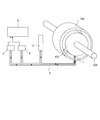
- FIG. 1 is a schematic diagram for explaining an optical sensor according to the present invention disposed in a rotating machine.
- the rotating machine includes a rotating body 103 that is fixed to a rotating shaft 102 in a housing 101 and arranged with a clearance from an inner peripheral surface of the housing 101.
- the optical sensor according to the present invention is provided in the rotating machine such that the tip is disposed on the inner peripheral surface of the housing 101 so as to face the peripheral surface of the rotating body 103.
- the optical sensor according to the present invention includes the sensor unit 1 and the first optical fiber arranged on the inner peripheral surface of the housing 101 so that the tip surface faces the rotating body 103 to be measured.
- a light-emitting device (light source) 2 connected to the sensor unit 1 via the second optical fiber, a first light-receiving device 3 connected to the sensor unit 1 via the second optical fiber, and a first connected to the sensor unit 1 via the third optical fiber.
- illumination light is output from the light emitting device 2 to the sensor unit 1 via the first optical fiber, and this illumination light is transmitted to the tip of the sensor unit 1 (sensor head). ) To the rotating body 103.
- Illumination light is reflected on the peripheral surface of the rotator 103, and a part of the reflected light enters the sensor head, passes through the second optical fiber to the first light receiving device 3, and passes through the third optical fiber. Each is input to the second light receiving device 4.
- the reflected light incident on the sensor head from the rotating body 103 has a predetermined intensity cycle depending on the shape or pattern changing in the circumferential direction (rotating direction) on the peripheral surface of the rotating body 103.
- This “shape” is, for example, the shape of a moving blade when the rotating body 103 is a turbine.
- the “pattern” refers to a pattern in which brightness and darkness are provided by attaching a marker or the like when there is no shape that changes in the circumferential direction on the peripheral surface of the rotating body 103.
- the measuring unit 5 measures the clearance from the rotating body 103 based on the timing of the reflected light (from the peripheral surface of the rotating body 103) input to the first light receiving device 3 and the second light receiving device 4, respectively.
- the above is the procedure for measuring the clearance of the rotating machine by the optical sensor according to the present invention.
- optical sensor according to the present invention will be described in detail in Examples.
- the present invention is not limited to this and can be applied to all rotating machines.
- the optical sensor according to the present invention measures the clearance if it is a moving body, not limited to the rotating body of a rotating machine, on the principle described in the following embodiment (the following formula (1) and FIG. 4). be able to.
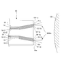
- Example 1 is a sectional view in the sensor axial direction (a sectional view parallel to the radial section of the rotating body 103) around the sensor head in an initial (normal) state of the conventional optical sensor, and FIG. 3B is a conventional optical sensor. It is a sensor axial direction sectional view around the sensor head in the state after becoming cloudy or worn out. First, the initial state will be described with reference to FIG. 3A.
- the front end surface 50a of the sensor head 50 is opposed to the peripheral surface of the rotating body 103, the illumination optical fibers 51 and 52 (first optical fiber), and the first light receiving optical fibers 53-1 and 53. -2, 53-3 (second optical fiber), and second light receiving optical fibers 54-1, 54-2, 54-3 (third optical fiber).
- Each of the illumination optical fibers 51 and 52 is connected to the light-emitting device 2 (see FIG. 1), and the other end faces (light-emitting portions) 51a and 52a are exposed at the tip face 50a. And it is an optical fiber as a propagation path which radiate
- Each of the first light receiving optical fibers 53-1, 53-2, and 53-3 has one end connected to the first light receiving device 3 (see FIG. 1) and the other end surfaces (light receiving portions) 53-1a and 53-3. -2a and 53-3a are exposed at the tip surface 50a. Then, the reflected light, which is the illumination light reflected by the peripheral surface of the rotator 103, is received (incident) by the end faces 53-1a, 53-2a, 53-3a, and is input to the first light receiving device 3. An optical fiber as a path.
- each of the second light receiving optical fibers 54-1, 54-2, 54-3 is connected to the second light receiving device 4 (see FIG. 1), and the other end surfaces (light receiving portions) 54-1a, 54-2a. , 54-3a are exposed at the tip surface 50a. Then, reflected light that is illumination light reflected by the peripheral surface of the rotating body 103 is received by the end faces 54-1a, 54-2a, and 54-3a, and is input to the second light receiving device 4 as a propagation path. It is an optical fiber.
- the first light receiving optical fibers 53-1, 53-2, 53-3 and the illumination optical fiber 51 are grouped into a set, and this is an optical fiber group P.
- the second light receiving optical fibers 54-1, 54-2, 54-3 and the illumination optical fiber 52 are grouped into one set, and this is an optical fiber group Q.
- the optical fiber groups P and Q extend substantially in the axial direction of the optical sensor, and within the sensor head 50, the separation distance from each other toward the distal end surface 50 a (in a cross-sectional view parallel to the radial cross section of the rotating body 103). It is inclined in a letter C in the spreading direction.
- the optical fiber groups P and Q include the positions and angles of the end faces 53-1a, 53-2a, 53-3a and the end face 51a, and the end faces 54-1a, 54-2a, 54-3a and the end faces on the tip face 50a.
- the position and angle of 52a are symmetrically arranged about the center line in the sensor axial direction of the optical sensor.
- FIG. 4 is a schematic diagram for explaining clearance (chip clearance) measurement by an optical sensor, taking a turbine as an example. ing.
- the positions of the end faces 54-1a, 54-2a, 54-3a and the end face 52a of the optical fiber group Q on the tip face 50a are point A (specifically, the positions of the end faces are four, but the optical fibers 54-1 and 54).
- ⁇ 2, 54-3 and 52 are adjacent to each other, and the positions (and angles) of the end faces are substantially the same, so they are regarded as one point), and the end face 53 ⁇ of the optical fiber group P
- the positions of 1a, 53-2a, 53-3a and the end face 51a are point B (similar to point A as one point).
- L be the separation distance between point A and point B, and imaginary straight line p orthogonal to end faces 53-1a, 53-2a, and 53-3a (similar to the above, in detail, one virtual straight line is divided into three A virtual straight line q orthogonal to the end faces 54-1a, 54-2a, 54-3a (similar to the above, in detail, three virtual straight lines are regarded as one), and a sensor
- the intersection of the three lines of the axial center line becomes the reference point O for distance measurement, and the intersection angle of the virtual straight lines p and q at the reference point O for distance measurement is ⁇ .
- angular part is a location where the intensity
- the time during which the moving blade 103a moves from point C to point D is ⁇ t, and the clearance (clearance to be measured) between the tip surface 31a of the optical sensor and the outer end surface 103b of the moving blade 103a is d.
- R is the radius of the rotating body and T is the period of the rotating body.
- each of the optical fiber groups p and q includes one light receiving optical fiber.
- the coefficient related to the illumination optical fiber does not appear in the above equation (1), the reflected light reflected by the rotating body 103 can be received by the light receiving optical fiber as long as the illumination light is reflected by the light receiving optical fiber.
- the end face may be at a position deviated from each of the points A and B (in this case, the points A and B indicate the position of only the end face of the light receiving optical fiber).
- the end face 50a has end faces 53-1a, 53-2a, 53-3a, 54-1a, 54-2a, 54-3a, and end faces 51a, 52a.
- a pipe having a metal pore fitted to the tip portion of the optical fiber can be provided, and the optical path can be reliably defined by the metal pore.
- the provision of the two metal plates having the through holes and the environment resistant window provides the above (1) even when each optical fiber is clouded or worn.
- the equation can be established, the clearance can be measured, and it can be easily manufactured as compared with the optical sensor described in Patent Document 1.
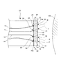
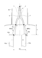
- FIG. 2A is a cross-sectional view in the sensor axial direction (that is, a cross-sectional view parallel to the radial cross-section of the rotating body 103) around the sensor head in the optical sensor according to the present embodiment
- FIG. 2B is a cross-sectional view taken along line AA in FIG.
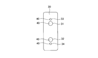
- FIG. 2C is a view taken along the line BB in FIG. 2A.
- the front end surface 10a of the sensor head 10 faces the peripheral surface of the rotating body 103, and the first illumination optical fiber 11 and the second illumination optical fiber. 12 (first optical fiber), a first light receiving optical fiber 13 (second optical fiber), and a second light receiving optical fiber 14 (third optical fiber).
- the first illumination optical fiber 11 has one end connected to the light emitting device 2 (see FIG. 1) and the other end face (light emitting portion) 11a exposed at the tip face 10a. And it is an optical fiber as a propagation path which radiate
- the second illumination optical fiber 12 has one end connected to the light emitting device 2 and the other end face (light emitting portion) 12a exposed at the tip face 10a. And it is an optical fiber as a propagation path which radiate
- the first illumination optical fiber 11 and the second illumination optical fiber 12 may be connected to different light emitting units.
- One end of the first light receiving optical fiber 13 is connected to the first light receiving device 3 (see FIG. 1), and the end face (light receiving portion) 13a at the other end is exposed at the tip face 10a.
- An optical fiber as a propagation path that receives reflected light, which is illumination light reflected by the peripheral surface of the rotating body 103, at the end surface 13 a and inputs the light to the first light receiving device 3.
- One end of the second light receiving optical fiber 14 is connected to the second light receiving device 4 (see FIG. 1), and the end face (light receiving portion) 14a at the other end is exposed at the tip face 10a.
- Each of the optical fibers 11 to 14 extends substantially in the axial direction of the optical sensor.
- the first light receiving optical fiber 13 and the second light receiving optical fiber 14 extend substantially in the axial direction of the optical sensor, and (at a cross sectional view parallel to the radial cross section of the rotating body 103) Inclined in the shape of a letter C in the direction in which the distance between them increases toward 10a.
- the first illumination optical fiber 11 and the second illumination optical fiber 12 are parallel to the radial cross section of the rotating body 103. (In a cross-sectional view) are arranged to be inclined in a letter C in a direction in which the distance from each other increases toward the tip surface 10a.
- FIG. 2A shows a state in which each of the optical fibers 11, 12, 13, and 14 is arranged one by one.
- the present embodiment is not limited to this, and a plurality of each is provided. Also good.
- the optical sensor according to the present embodiment is measured from the first metal plate 20 (first plate material), which is arranged in close contact with the tip surface 10a in parallel, parallel to the first metal plate 20 and from the first metal plate 20.
- the second metal plate 30 (second plate material) disposed on the front side in the direction (rotating body 103 side), and the environment-resistant window inserted and fixed between the first metal plate 20 and the second metal plate 30 40, which defines the light receiving direction.
- the first metal plate 20 has a first inner through hole 21 formed at a position corresponding to the end surface 11a exposed from the tip surface 10a, and a second inner side formed at a position corresponding to the end surface 12a exposed from the tip surface 10a.
- a through hole 24 is provided.
- the second metal plate 30 is formed at the intersection with the first outer through hole 31 formed at the intersection with the virtual straight line W (identical to the virtual line q) orthogonal to the end surface 11a and the virtual straight line X orthogonal to the end surface 12a.
- the fourth outer through-hole 34 is formed at the intersection.
- first outer through hole 31 and the second outer through hole 32 are larger in diameter than the third outer through hole 33 and the fourth outer through hole 34. This is because the through holes 31 and 32 are through holes for illumination light, and it is preferable that the illumination light is emitted to the rotating body 103 with a certain extent without being reduced.
- the environment-resistant window 40 has a light-transmitting property to transmit illumination light and reflected light, and is made of a material resistant to high heat and high vapor, such as diamond or sapphire (this embodiment is resistant to heat). Although the material of the environmental window 40 is not limited, the environmental window 40 needs to have higher resistance to temperature and steam than at least each optical fiber). Further, the environment-resistant window 40 may be embedded in the through holes 21 to 24 of the first metal plate 20 instead of being inserted between the first metal plate 20 and the second metal plate 30. .
- the optical sensor In the optical sensor according to the present embodiment, first, in the first metal plate 20 and the second metal plate 30, two through holes (the through hole 23 and the through hole 33 or the through hole 24) of these two metal plates are used. Since only the reflected light passing through the through hole 34) is received, the light receiving optical path is defined (similarly, the illumination optical path is also defined). Therefore, even if white turbidity or wear occurs near the end of each optical fiber exposed to harsh environments such as high temperature and high steam environment, the light receiving direction is not affected, and the value of ⁇ in the above equation (1) is not affected. Since there is no fluctuation, the clearance can be measured.
- each optical fiber is not affected even in a high temperature / high steam environment. Therefore, accurate clearance measurement is possible.
- the illumination optical fibers 11 and 12 and the light receiving optical fibers 13 and 14 are spaced apart from each other on the distal end surface 10a. This enables more accurate clearance measurement.
- the environment-resistant window 40 is simply attached between the plate materials (the first metal plate 20 and the second metal plate 30) having the through holes, which is described in Patent Document 1 described above. As compared with metal pore processing, it is advantageous in feasibility and workability.
- the tip surface of the sensor head is parallel to the moving direction with respect to the moving body to be measured. Similar results can be obtained by making them face each other.
- the present invention is suitable as an optical sensor.
Landscapes
- Physics & Mathematics (AREA)
- General Physics & Mathematics (AREA)
- Engineering & Computer Science (AREA)
- Mechanical Engineering (AREA)
- General Engineering & Computer Science (AREA)
- Length Measuring Devices By Optical Means (AREA)
Priority Applications (2)
| Application Number | Priority Date | Filing Date | Title |
|---|---|---|---|
| CN201780034865.1A CN109313013B (zh) | 2016-06-07 | 2017-06-07 | 光学传感器 |
| US16/308,054 US10760897B2 (en) | 2016-06-07 | 2017-06-07 | Optical sensor |
Applications Claiming Priority (2)
| Application Number | Priority Date | Filing Date | Title |
|---|---|---|---|
| JP2016-113203 | 2016-06-07 | ||
| JP2016113203A JP6599285B2 (ja) | 2016-06-07 | 2016-06-07 | 光学センサ |
Publications (1)
| Publication Number | Publication Date |
|---|---|
| WO2017213161A1 true WO2017213161A1 (ja) | 2017-12-14 |
Family
ID=60578614
Family Applications (1)
| Application Number | Title | Priority Date | Filing Date |
|---|---|---|---|
| PCT/JP2017/021053 Ceased WO2017213161A1 (ja) | 2016-06-07 | 2017-06-07 | 光学センサ |
Country Status (4)
| Country | Link |
|---|---|
| US (1) | US10760897B2 (enExample) |
| JP (1) | JP6599285B2 (enExample) |
| CN (1) | CN109313013B (enExample) |
| WO (1) | WO2017213161A1 (enExample) |
Families Citing this family (2)
| Publication number | Priority date | Publication date | Assignee | Title |
|---|---|---|---|---|
| US12339113B2 (en) * | 2022-06-30 | 2025-06-24 | Ge Infrastructure Technology Llc | Apparatus and method for transmitting radiation to a rotating component |
| US12692798B2 (en) | 2023-10-13 | 2026-07-28 | Ge Infrastructure Technology Llc | Apparatus for diverting radiation emitted from source |
Citations (7)
| Publication number | Priority date | Publication date | Assignee | Title |
|---|---|---|---|---|
| JPH0518981A (ja) * | 1991-07-10 | 1993-01-26 | Nippon Kagaku Kogyo Kk | 気液二相流の計測装置 |
| US5274721A (en) * | 1992-03-05 | 1993-12-28 | American Sigma, Inc. | Fiber optic system and method |
| JPH0763509A (ja) * | 1993-06-30 | 1995-03-10 | Mitsubishi Rayon Co Ltd | 光ファイバセンサヘッド |
| JP2004191374A (ja) * | 2002-12-12 | 2004-07-08 | Siemens Ag | 距離測定方法および距離測定装置 |
| JP2004333470A (ja) * | 2003-05-07 | 2004-11-25 | Mitsutoyo Corp | 光ファイバ受信器チャネルを使用した2次元測定装置 |
| JP2005326362A (ja) * | 2004-05-17 | 2005-11-24 | Keyence Corp | 光電センサ |
| JP2015001414A (ja) * | 2013-06-14 | 2015-01-05 | 三菱重工業株式会社 | チップクリアランス計測装置 |
Family Cites Families (15)
| Publication number | Priority date | Publication date | Assignee | Title |
|---|---|---|---|---|
| US4275965A (en) * | 1979-08-21 | 1981-06-30 | United Technologies Corporation | Long stroke, high resolution optical position sensor |
| JPS59134026A (ja) | 1983-01-24 | 1984-08-01 | Nissan Motor Co Ltd | 自動車用キヤリア |
| US5299141A (en) | 1989-12-22 | 1994-03-29 | American Sigma, Inc. | Automatic fluid monitoring and sampling apparatus and method |
| JPH10132752A (ja) | 1996-09-04 | 1998-05-22 | Asahi Kooden Kk | ライトガイド |
| ATE247183T1 (de) | 1997-11-06 | 2003-08-15 | Eastman Chem Co | Copolyester-binderfasern |
| JP3854056B2 (ja) * | 1999-12-13 | 2006-12-06 | 株式会社荏原製作所 | 基板膜厚測定方法、基板膜厚測定装置、基板処理方法及び基板処理装置 |
| MXPA03006104A (es) * | 2001-01-09 | 2005-10-05 | Takahiko Mukouda | Componente conector para fibra optica multifilar, manguito de empalme y metodo para fabricar los mismos. |
| US20040125702A1 (en) * | 2002-10-21 | 2004-07-01 | Hideki Kitajima | Rotational position detection device, hand position detection device and clock using the hand position detection device |
| JP2004246279A (ja) * | 2003-02-17 | 2004-09-02 | Seiko Epson Corp | 光モジュール及びその製造方法、光通信装置、光電気混載集積回路、回路基板、電子機器 |
| US20080291456A1 (en) * | 2007-05-24 | 2008-11-27 | Ghislain Lucien P | Sensor apparatus and method using optical interferometry |
| KR200444690Y1 (ko) * | 2009-02-03 | 2009-05-28 | (주)위니테크놀러지 | 광케이블 여장처리구조가 구비된 다심형 화이버 광스위치 모듈 |
| CN201477265U (zh) * | 2009-08-19 | 2010-05-19 | 浙江万马集团电子有限公司 | 光分路器模块夹具插片 |
| CN201965258U (zh) | 2010-12-10 | 2011-09-07 | 富士康(昆山)电脑接插件有限公司 | 光纤连接器 |
| CN202166608U (zh) | 2011-06-30 | 2012-03-14 | 深圳市汇松科技发展有限公司 | 一种多通道酶标仪的检测体组 |
| CN104501728A (zh) * | 2014-12-12 | 2015-04-08 | 天津大学 | 一种基于全光纤叶尖定时的叶尖间隙测量方法 |
-
2016
- 2016-06-07 JP JP2016113203A patent/JP6599285B2/ja active Active
-
2017
- 2017-06-07 WO PCT/JP2017/021053 patent/WO2017213161A1/ja not_active Ceased
- 2017-06-07 CN CN201780034865.1A patent/CN109313013B/zh active Active
- 2017-06-07 US US16/308,054 patent/US10760897B2/en active Active
Patent Citations (7)
| Publication number | Priority date | Publication date | Assignee | Title |
|---|---|---|---|---|
| JPH0518981A (ja) * | 1991-07-10 | 1993-01-26 | Nippon Kagaku Kogyo Kk | 気液二相流の計測装置 |
| US5274721A (en) * | 1992-03-05 | 1993-12-28 | American Sigma, Inc. | Fiber optic system and method |
| JPH0763509A (ja) * | 1993-06-30 | 1995-03-10 | Mitsubishi Rayon Co Ltd | 光ファイバセンサヘッド |
| JP2004191374A (ja) * | 2002-12-12 | 2004-07-08 | Siemens Ag | 距離測定方法および距離測定装置 |
| JP2004333470A (ja) * | 2003-05-07 | 2004-11-25 | Mitsutoyo Corp | 光ファイバ受信器チャネルを使用した2次元測定装置 |
| JP2005326362A (ja) * | 2004-05-17 | 2005-11-24 | Keyence Corp | 光電センサ |
| JP2015001414A (ja) * | 2013-06-14 | 2015-01-05 | 三菱重工業株式会社 | チップクリアランス計測装置 |
Also Published As
| Publication number | Publication date |
|---|---|
| CN109313013B (zh) | 2021-06-01 |
| JP6599285B2 (ja) | 2019-10-30 |
| US10760897B2 (en) | 2020-09-01 |
| JP2017219391A (ja) | 2017-12-14 |
| US20190310075A1 (en) | 2019-10-10 |
| CN109313013A (zh) | 2019-02-05 |
Similar Documents
| Publication | Publication Date | Title |
|---|---|---|
| CN203100688U (zh) | 一种测量旋转叶片叶尖间隙的光纤传感器 | |
| ATE414273T1 (de) | Vorrichtung zur inspektion einer oberfläche | |
| CN109416244B (zh) | 间隙计测装置和间隙控制系统 | |
| CN104215197B (zh) | 基于低反射率三芯光纤光栅阵列空间形状测量装置及方法 | |
| KR101954300B1 (ko) | 투과 및/또는 반사 특성을 판단하기 위한 측정방법 및 측정기기 | |
| RU2009124266A (ru) | Волоконно-оптическая система и способ измерения множественных параметров турбомашинной системы | |
| US9791594B2 (en) | Light grid with detection by adjacent light reception units arranged opposite light transmission units | |
| JP6599285B2 (ja) | 光学センサ | |
| CN104501728A (zh) | 一种基于全光纤叶尖定时的叶尖间隙测量方法 | |
| WO2017159770A1 (ja) | 光計測装置、光計測方法及び回転機械 | |
| JP6959027B2 (ja) | クリアランス計測装置、クリアランス計測センサ及びクリアランス計測方法 | |
| CN102607696B (zh) | 一种用于led测试机的积分球 | |
| CN102607412A (zh) | 视觉测量系统中相机转动轴位置测量方法 | |
| JP2013205332A (ja) | 欠点検査装置および欠点検査方法 | |
| CN108885091B (zh) | 光学传感器及旋转机械 | |
| CN101571479A (zh) | 基于线阵ccd的光学液体浓度测量装置及测量方法 | |
| CN204422058U (zh) | 一种基于激光的桥梁振动检测装置 | |
| CN202748013U (zh) | 一种用于内窥的多模式结构光投射装置 | |
| JP2017219391A5 (enExample) | ||
| ATE487116T1 (de) | System und verfahren zum messen von distanzen, verschiebungen und mechanischen einwirkungen | |
| KR101551259B1 (ko) | 광세기 기반 광섬유 센서 헤드 | |
| WO2017164149A1 (ja) | 光学センサ、回転機械及びクリアランス計測方法 | |
| CN109931887A (zh) | 一种角度传感器 | |
| JP3191955U (ja) | 反射器及びこれを用いた外観検査用ライト | |
| Casalicchio et al. | Low-cost 2D fiber-based displacement sensor |
Legal Events
| Date | Code | Title | Description |
|---|---|---|---|
| 121 | Ep: the epo has been informed by wipo that ep was designated in this application |
Ref document number: 17810335 Country of ref document: EP Kind code of ref document: A1 |
|
| NENP | Non-entry into the national phase |
Ref country code: DE |
|
| 122 | Ep: pct application non-entry in european phase |
Ref document number: 17810335 Country of ref document: EP Kind code of ref document: A1 |