WO2017213082A1 - 選択型ビーム積層造形装置及び選択型ビーム積層造形方法 - Google Patents
選択型ビーム積層造形装置及び選択型ビーム積層造形方法 Download PDFInfo
- Publication number
- WO2017213082A1 WO2017213082A1 PCT/JP2017/020821 JP2017020821W WO2017213082A1 WO 2017213082 A1 WO2017213082 A1 WO 2017213082A1 JP 2017020821 W JP2017020821 W JP 2017020821W WO 2017213082 A1 WO2017213082 A1 WO 2017213082A1
- Authority
- WO
- WIPO (PCT)
- Prior art keywords
- heating
- modeling
- powder bed
- heating beam
- irradiation
- Prior art date
- Legal status (The legal status is an assumption and is not a legal conclusion. Google has not performed a legal analysis and makes no representation as to the accuracy of the status listed.)
- Ceased
Links
Images


Classifications
-
- B—PERFORMING OPERATIONS; TRANSPORTING
- B29—WORKING OF PLASTICS; WORKING OF SUBSTANCES IN A PLASTIC STATE IN GENERAL
- B29C—SHAPING OR JOINING OF PLASTICS; SHAPING OF MATERIAL IN A PLASTIC STATE, NOT OTHERWISE PROVIDED FOR; AFTER-TREATMENT OF THE SHAPED PRODUCTS, e.g. REPAIRING
- B29C64/00—Additive manufacturing, i.e. manufacturing of three-dimensional [3D] objects by additive deposition, additive agglomeration or additive layering, e.g. by 3D printing, stereolithography or selective laser sintering
- B29C64/20—Apparatus for additive manufacturing; Details thereof or accessories therefor
- B29C64/264—Arrangements for irradiation
- B29C64/268—Arrangements for irradiation using laser beams; using electron beams [EB]
-
- B—PERFORMING OPERATIONS; TRANSPORTING
- B22—CASTING; POWDER METALLURGY
- B22F—WORKING METALLIC POWDER; MANUFACTURE OF ARTICLES FROM METALLIC POWDER; MAKING METALLIC POWDER; APPARATUS OR DEVICES SPECIALLY ADAPTED FOR METALLIC POWDER
- B22F10/00—Additive manufacturing of workpieces or articles from metallic powder
- B22F10/20—Direct sintering or melting
- B22F10/28—Powder bed fusion, e.g. selective laser melting [SLM] or electron beam melting [EBM]
-
- B—PERFORMING OPERATIONS; TRANSPORTING
- B22—CASTING; POWDER METALLURGY
- B22F—WORKING METALLIC POWDER; MANUFACTURE OF ARTICLES FROM METALLIC POWDER; MAKING METALLIC POWDER; APPARATUS OR DEVICES SPECIALLY ADAPTED FOR METALLIC POWDER
- B22F10/00—Additive manufacturing of workpieces or articles from metallic powder
- B22F10/30—Process control
- B22F10/36—Process control of energy beam parameters
- B22F10/362—Process control of energy beam parameters for preheating
-
- B—PERFORMING OPERATIONS; TRANSPORTING
- B22—CASTING; POWDER METALLURGY
- B22F—WORKING METALLIC POWDER; MANUFACTURE OF ARTICLES FROM METALLIC POWDER; MAKING METALLIC POWDER; APPARATUS OR DEVICES SPECIALLY ADAPTED FOR METALLIC POWDER
- B22F10/00—Additive manufacturing of workpieces or articles from metallic powder
- B22F10/30—Process control
- B22F10/36—Process control of energy beam parameters
- B22F10/366—Scanning parameters, e.g. hatch distance or scanning strategy
-
- B—PERFORMING OPERATIONS; TRANSPORTING
- B22—CASTING; POWDER METALLURGY
- B22F—WORKING METALLIC POWDER; MANUFACTURE OF ARTICLES FROM METALLIC POWDER; MAKING METALLIC POWDER; APPARATUS OR DEVICES SPECIALLY ADAPTED FOR METALLIC POWDER
- B22F12/00—Apparatus or devices specially adapted for additive manufacturing; Auxiliary means for additive manufacturing; Combinations of additive manufacturing apparatus or devices with other processing apparatus or devices
- B22F12/10—Auxiliary heating means
- B22F12/13—Auxiliary heating means to preheat the material
-
- B—PERFORMING OPERATIONS; TRANSPORTING
- B22—CASTING; POWDER METALLURGY
- B22F—WORKING METALLIC POWDER; MANUFACTURE OF ARTICLES FROM METALLIC POWDER; MAKING METALLIC POWDER; APPARATUS OR DEVICES SPECIALLY ADAPTED FOR METALLIC POWDER
- B22F3/00—Manufacture of workpieces or articles from metallic powder characterised by the manner of compacting or sintering; Apparatus specially adapted therefor ; Presses and furnaces
- B22F3/10—Sintering only
- B22F3/105—Sintering only by using electric current other than for infrared radiant energy, laser radiation or plasma ; by ultrasonic bonding
-
- B—PERFORMING OPERATIONS; TRANSPORTING
- B22—CASTING; POWDER METALLURGY
- B22F—WORKING METALLIC POWDER; MANUFACTURE OF ARTICLES FROM METALLIC POWDER; MAKING METALLIC POWDER; APPARATUS OR DEVICES SPECIALLY ADAPTED FOR METALLIC POWDER
- B22F3/00—Manufacture of workpieces or articles from metallic powder characterised by the manner of compacting or sintering; Apparatus specially adapted therefor ; Presses and furnaces
- B22F3/12—Both compacting and sintering
- B22F3/16—Both compacting and sintering in successive or repeated steps
-
- B—PERFORMING OPERATIONS; TRANSPORTING
- B29—WORKING OF PLASTICS; WORKING OF SUBSTANCES IN A PLASTIC STATE IN GENERAL
- B29C—SHAPING OR JOINING OF PLASTICS; SHAPING OF MATERIAL IN A PLASTIC STATE, NOT OTHERWISE PROVIDED FOR; AFTER-TREATMENT OF THE SHAPED PRODUCTS, e.g. REPAIRING
- B29C64/00—Additive manufacturing, i.e. manufacturing of three-dimensional [3D] objects by additive deposition, additive agglomeration or additive layering, e.g. by 3D printing, stereolithography or selective laser sintering
- B29C64/10—Processes of additive manufacturing
- B29C64/141—Processes of additive manufacturing using only solid materials
- B29C64/153—Processes of additive manufacturing using only solid materials using layers of powder being selectively joined, e.g. by selective laser sintering or melting
-
- B—PERFORMING OPERATIONS; TRANSPORTING
- B29—WORKING OF PLASTICS; WORKING OF SUBSTANCES IN A PLASTIC STATE IN GENERAL
- B29C—SHAPING OR JOINING OF PLASTICS; SHAPING OF MATERIAL IN A PLASTIC STATE, NOT OTHERWISE PROVIDED FOR; AFTER-TREATMENT OF THE SHAPED PRODUCTS, e.g. REPAIRING
- B29C64/00—Additive manufacturing, i.e. manufacturing of three-dimensional [3D] objects by additive deposition, additive agglomeration or additive layering, e.g. by 3D printing, stereolithography or selective laser sintering
- B29C64/20—Apparatus for additive manufacturing; Details thereof or accessories therefor
- B29C64/264—Arrangements for irradiation
- B29C64/277—Arrangements for irradiation using multiple radiation means, e.g. micromirrors or multiple light-emitting diodes [LED]
-
- B—PERFORMING OPERATIONS; TRANSPORTING
- B29—WORKING OF PLASTICS; WORKING OF SUBSTANCES IN A PLASTIC STATE IN GENERAL
- B29C—SHAPING OR JOINING OF PLASTICS; SHAPING OF MATERIAL IN A PLASTIC STATE, NOT OTHERWISE PROVIDED FOR; AFTER-TREATMENT OF THE SHAPED PRODUCTS, e.g. REPAIRING
- B29C64/00—Additive manufacturing, i.e. manufacturing of three-dimensional [3D] objects by additive deposition, additive agglomeration or additive layering, e.g. by 3D printing, stereolithography or selective laser sintering
- B29C64/20—Apparatus for additive manufacturing; Details thereof or accessories therefor
- B29C64/295—Heating elements
-
- B—PERFORMING OPERATIONS; TRANSPORTING
- B29—WORKING OF PLASTICS; WORKING OF SUBSTANCES IN A PLASTIC STATE IN GENERAL
- B29C—SHAPING OR JOINING OF PLASTICS; SHAPING OF MATERIAL IN A PLASTIC STATE, NOT OTHERWISE PROVIDED FOR; AFTER-TREATMENT OF THE SHAPED PRODUCTS, e.g. REPAIRING
- B29C64/00—Additive manufacturing, i.e. manufacturing of three-dimensional [3D] objects by additive deposition, additive agglomeration or additive layering, e.g. by 3D printing, stereolithography or selective laser sintering
- B29C64/30—Auxiliary operations or equipment
- B29C64/386—Data acquisition or data processing for additive manufacturing
- B29C64/393—Data acquisition or data processing for additive manufacturing for controlling or regulating additive manufacturing processes
-
- B—PERFORMING OPERATIONS; TRANSPORTING
- B33—ADDITIVE MANUFACTURING TECHNOLOGY
- B33Y—ADDITIVE MANUFACTURING, i.e. MANUFACTURING OF THREE-DIMENSIONAL [3-D] OBJECTS BY ADDITIVE DEPOSITION, ADDITIVE AGGLOMERATION OR ADDITIVE LAYERING, e.g. BY 3-D PRINTING, STEREOLITHOGRAPHY OR SELECTIVE LASER SINTERING
- B33Y10/00—Processes of additive manufacturing
-
- B—PERFORMING OPERATIONS; TRANSPORTING
- B33—ADDITIVE MANUFACTURING TECHNOLOGY
- B33Y—ADDITIVE MANUFACTURING, i.e. MANUFACTURING OF THREE-DIMENSIONAL [3-D] OBJECTS BY ADDITIVE DEPOSITION, ADDITIVE AGGLOMERATION OR ADDITIVE LAYERING, e.g. BY 3-D PRINTING, STEREOLITHOGRAPHY OR SELECTIVE LASER SINTERING
- B33Y30/00—Apparatus for additive manufacturing; Details thereof or accessories therefor
-
- B—PERFORMING OPERATIONS; TRANSPORTING
- B22—CASTING; POWDER METALLURGY
- B22F—WORKING METALLIC POWDER; MANUFACTURE OF ARTICLES FROM METALLIC POWDER; MAKING METALLIC POWDER; APPARATUS OR DEVICES SPECIALLY ADAPTED FOR METALLIC POWDER
- B22F10/00—Additive manufacturing of workpieces or articles from metallic powder
- B22F10/30—Process control
- B22F10/32—Process control of the atmosphere, e.g. composition or pressure in a building chamber
-
- B—PERFORMING OPERATIONS; TRANSPORTING
- B22—CASTING; POWDER METALLURGY
- B22F—WORKING METALLIC POWDER; MANUFACTURE OF ARTICLES FROM METALLIC POWDER; MAKING METALLIC POWDER; APPARATUS OR DEVICES SPECIALLY ADAPTED FOR METALLIC POWDER
- B22F12/00—Apparatus or devices specially adapted for additive manufacturing; Auxiliary means for additive manufacturing; Combinations of additive manufacturing apparatus or devices with other processing apparatus or devices
- B22F12/40—Radiation means
- B22F12/49—Scanners
-
- B—PERFORMING OPERATIONS; TRANSPORTING
- B22—CASTING; POWDER METALLURGY
- B22F—WORKING METALLIC POWDER; MANUFACTURE OF ARTICLES FROM METALLIC POWDER; MAKING METALLIC POWDER; APPARATUS OR DEVICES SPECIALLY ADAPTED FOR METALLIC POWDER
- B22F12/00—Apparatus or devices specially adapted for additive manufacturing; Auxiliary means for additive manufacturing; Combinations of additive manufacturing apparatus or devices with other processing apparatus or devices
- B22F12/50—Means for feeding of material, e.g. heads
- B22F12/52—Hoppers
-
- B—PERFORMING OPERATIONS; TRANSPORTING
- B22—CASTING; POWDER METALLURGY
- B22F—WORKING METALLIC POWDER; MANUFACTURE OF ARTICLES FROM METALLIC POWDER; MAKING METALLIC POWDER; APPARATUS OR DEVICES SPECIALLY ADAPTED FOR METALLIC POWDER
- B22F12/00—Apparatus or devices specially adapted for additive manufacturing; Auxiliary means for additive manufacturing; Combinations of additive manufacturing apparatus or devices with other processing apparatus or devices
- B22F12/50—Means for feeding of material, e.g. heads
- B22F12/55—Two or more means for feeding material
-
- B—PERFORMING OPERATIONS; TRANSPORTING
- B33—ADDITIVE MANUFACTURING TECHNOLOGY
- B33Y—ADDITIVE MANUFACTURING, i.e. MANUFACTURING OF THREE-DIMENSIONAL [3-D] OBJECTS BY ADDITIVE DEPOSITION, ADDITIVE AGGLOMERATION OR ADDITIVE LAYERING, e.g. BY 3-D PRINTING, STEREOLITHOGRAPHY OR SELECTIVE LASER SINTERING
- B33Y50/00—Data acquisition or data processing for additive manufacturing
- B33Y50/02—Data acquisition or data processing for additive manufacturing for controlling or regulating additive manufacturing processes
-
- Y—GENERAL TAGGING OF NEW TECHNOLOGICAL DEVELOPMENTS; GENERAL TAGGING OF CROSS-SECTIONAL TECHNOLOGIES SPANNING OVER SEVERAL SECTIONS OF THE IPC; TECHNICAL SUBJECTS COVERED BY FORMER USPC CROSS-REFERENCE ART COLLECTIONS [XRACs] AND DIGESTS
- Y02—TECHNOLOGIES OR APPLICATIONS FOR MITIGATION OR ADAPTATION AGAINST CLIMATE CHANGE
- Y02P—CLIMATE CHANGE MITIGATION TECHNOLOGIES IN THE PRODUCTION OR PROCESSING OF GOODS
- Y02P10/00—Technologies related to metal processing
- Y02P10/25—Process efficiency
Definitions
- the present disclosure relates to a selective beam additive manufacturing apparatus and a selective beam additive manufacturing method.
- the selective beam additive manufacturing apparatus includes a base plate, a powder bed forming apparatus capable of forming a powder bed on the base plate, and a beam irradiation apparatus capable of selectively irradiating a part of the powder bed.
- a part of the particles in the powder bed is selectively irradiated by irradiating each powder bed with the beam while repeating the lamination of the powder beds. It is possible to produce a shaped article by melting and solidifying.
- the powder bed is preheated.
- the surface of a component bed is preheated by a radiation heat dissipation element.
- the entire surface of the powder bed is irradiated while scanning the electron beam at a high speed to preheat the powder bed.
- the preheating of the powder bed is performed by lightly adhering or pre-sintering the particles in the powder to prevent partial charging of the powder bed when irradiated with an electron beam for modeling. This is to prevent the smoking phenomenon.
- the selective beam additive manufacturing apparatus using an electron beam also has a problem that a modeled object having a complicated internal structure may not be produced due to preheating of the entire powder bed by the electron beam.
- an object of at least one embodiment of the present invention is to provide a selective beam additive manufacturing apparatus capable of reducing a residual stress of a modeled object and capable of producing a high-quality modeled object having a complicated internal structure. And providing a selective beam additive manufacturing method.
- a selective beam additive manufacturing apparatus includes: A frame, A base plate capable of moving up and down in the frame; A powder bed forming unit capable of forming a powder bed on the base plate; A modeling beam irradiation unit capable of irradiating a modeling beam to the powder bed; A heating beam irradiation unit capable of irradiating the powder bed with a heating beam having a lower output than the modeling beam; A control device capable of controlling the beam irradiation unit for modeling and the beam irradiation unit for heating, and The controller is The modeling beam irradiation unit is configured to be controllable so that the modeling beam is irradiated to the powder bed along a setting route corresponding to the shape of the target modeling object. And The heating beam irradiation unit is configured to be able to control the modeling beam irradiation unit so as to irradiate the powder beam bed with the heating beam along the set route.
- the powder beam can be irradiated with a beam for heating and a heating beam having a lower output than the beam for modeling along the set route. It is possible to heat locally with a heating beam. For this reason, the particles of the powder bed are prevented from adhering to each other in an undesired region, so that even if a modeled object having a complicated internal structure is produced, the powder in the modeled object can be easily removed. Can do.
- the region irradiated with the modeling beam can be heated by the heating beam, it is possible to reduce the residual stress of the modeled object and to suppress generation of cracks and voids in the modeled object. It is possible to produce a high-quality molded article.
- the region irradiated with the modeling beam may be a region irradiated with the modeling beam, may be a region scheduled to be irradiated with the modeling beam, or the modeling beam may be irradiated. It may be a region that has already been irradiated.
- the control device is configured to change the profile shape of the heating beam on the powder bed.
- the powder bed can be locally heated by the heating beam under various conditions by changing the profile shape of the heating beam. For this reason, according to the said structure (2), while being able to reduce the residual stress of a molded article reliably, the high quality molded article which has a complicated internal structure can be produced reliably.
- the control device is configured to be able to change a relative positional relationship between the irradiation position of the shaping beam and the irradiation position of the heating beam in the powder bed.
- the powder bed is heated by the heating beam under various conditions. It can be heated locally. For this reason, according to the said structure (3), while being able to reduce the residual stress of a molded article reliably, the high quality molded article which has a complicated internal structure can be produced reliably.
- the control device is configured to scan the heating beam in a wave shape traveling along the set route in the powder bed.
- the control device is configured to be able to scan the heating beam in a wave shape that travels along the set route, the heating beam is applied to the area irradiated with the modeling beam and its periphery. It can be heated sufficiently without being concentrated. For this reason, according to the said structure (4), while being able to reduce the residual stress of a molded article reliably, the high quality molded article which has a complicated internal structure can be produced reliably.
- the modeling beam irradiation unit also serves as the heating beam irradiation unit
- the control device is configured to be able to irradiate the modeling beam and the heating beam at different timings.
- the modeling beam irradiation unit also serves as the heating beam irradiation unit, it is possible to reduce the residual stress of the modeled object with a simple configuration and to have a complicated internal structure. It is possible to produce a quality model.
- the control device is configured to control the modeling beam in the powder bed according to at least one of a scanning direction of the modeling beam, a material constituting the powder bed, and a time to be preheated by the heating beam. At least among a relative positional relationship between an irradiation position and an irradiation position of the heating beam, a profile shape of the heating beam on the powder bed, and a scanning direction of the heating beam on the powder bed One is configured to be changeable.
- the modeling beam on the powder bed At least one of a relative positional relationship between the irradiation position and the irradiation position of the heating beam, a profile shape of the heating beam on the powder bed, and a scanning direction of the heating beam on the powder bed;
- the selective beam additive manufacturing method includes: A powder bed forming step of forming a powder bed on a base plate arranged to be movable up and down in the frame; For the powder bed, along with a set route corresponding to the shape of the target modeled object, a modeling beam irradiation step of irradiating a modeling beam, A heating beam irradiation step of irradiating the powder bed with a heating beam having a lower output than the modeling beam along the set route, Is provided.
- the powder beam is irradiated with the modeling beam and the heating beam having a lower output than the modeling beam along the set route, so that the region irradiated with the modeling beam is heated. It is possible to heat locally by the working beam. For this reason, the particles of the powder bed are prevented from adhering to each other in an undesired region, so that even if a modeled object having a complicated internal structure is produced, the powder in the modeled object can be easily removed. Can do.
- the region irradiated with the modeling beam can be heated by the heating beam, it is possible to reduce the residual stress of the modeled object and to suppress generation of cracks and voids in the modeled object.
- the region irradiated with the modeling beam may be a region irradiated with the modeling beam, may be a region scheduled to be irradiated with the modeling beam, or the modeling beam may be irradiated. It may be a region that has already been irradiated.
- the heating beam having a circular or rectangular beam shape is irradiated.
- the residual stress of a molded article can be reduced by irradiating the heating beam which has a circular or rectangular beam shape, and high quality modeling which has a complicated internal structure Can be made.
- the heating beam having a beam diameter larger than the beam diameter of the modeling beam is irradiated.
- the heating beam by irradiating the heating beam having a beam diameter larger than the beam diameter of the modeling beam, the region irradiated with the modeling beam and its periphery are heated by the heating beam. be able to. For this reason, according to the said structure (9), while being able to reduce the residual stress of a molded article, the high quality molded article which has a complicated internal structure is producible.
- the heating beam is irradiated while scanning the powder bed in a wave shape that travels along the set route.
- the heating beam is scanned in a wave shape that travels along the set route, the region irradiated with the modeling beam and its surroundings are sufficiently heated without concentrating the heating beam. can do.
- the said structure (10) while being able to reduce the residual stress of a molded article reliably, the high quality molded article which has a complicated internal structure can be produced reliably.
- the heating beam is irradiated such that the irradiation position of the modeling beam on the powder bed is positioned at the center of the irradiation position of the heating beam in the scanning direction of the modeling beam. Irradiate the beam.
- the heating beam is irradiated so that the irradiation position of the modeling beam on the powder bed is positioned at the center of the irradiation position of the heating beam in the scanning direction of the modeling beam. Therefore, the region to be irradiated with the modeling beam can be heated in advance by the heating beam, and the region already irradiated with the modeling beam can be heated later. For this reason, according to the said structure (11), while being able to reduce the residual stress of a molded article reliably, the high quality molded article which has a complicated internal structure can be produced reliably.
- the irradiation position of the modeling beam on the powder bed is positioned behind the center of the irradiation position of the heating beam in the scanning direction of the modeling beam. Irradiate a heating beam.
- the heating beam is placed so that the irradiation position of the modeling beam on the powder bed is located behind the center of the irradiation position of the heating beam in the scanning direction of the modeling beam. Since irradiation is performed, the region to be irradiated with the modeling beam can be preheated by the heating beam. For this reason, according to the said structure (12), while being able to reduce the residual stress of a molded article reliably, the high quality molded article which has a complicated internal structure can be produced reliably.
- the irradiation position of the modeling beam on the powder bed is positioned forward of the center of the irradiation position of the heating beam in the scanning direction of the modeling beam. Irradiate a heating beam.
- the heating beam is placed so that the irradiation position of the modeling beam on the powder bed is positioned in front of the center of the irradiation position of the heating beam in the scanning direction of the modeling beam. Since it irradiates, the area
- the heating beam irradiation step according to at least one of a scanning direction of the modeling beam, a material constituting the powder bed, and a time to be preheated by the heating beam, the powder bed Relative positional relationship between the irradiation position of the modeling beam and the irradiation position of the heating beam, the profile shape of the heating beam on the powder bed, and the heating beam on the powder bed At least one of the scanning directions is changed.
- the modeling beam in a powder bed At least one of a relative positional relationship between the irradiation position and the irradiation position of the heating beam, a profile shape of the heating beam on the powder bed, and a scanning direction of the heating beam on the powder bed;
- a selective beam additive manufacturing apparatus and a selective beam additive manufacturing capable of reducing a residual stress of an object and capable of producing a high-quality object having a complicated internal structure. A method is provided.
- FIG. 1 is a diagram illustrating a schematic configuration of a selective beam additive manufacturing apparatus according to an embodiment of the present invention. It is a graph which shows roughly an example of the profile shape of the beam for modeling and the beam for heating with which the powder bed was irradiated with the selective beam layered modeling apparatus of FIG. It is a figure which shows schematically the beam shape of the beam for modeling and the beam for a heating which has the profile shape of FIG. 2 in a powder bed. It is a graph which shows roughly an example of the profile shape of the beam for modeling and the beam for heating with which the powder bed was irradiated with the selective beam layered modeling apparatus of FIG. It is a figure which shows schematically the beam shape of the beam for modeling and the beam for a heating which have the profile shape of FIG.
- an expression indicating that things such as “identical”, “equal”, and “homogeneous” are in an equal state not only represents an exactly equal state, but also has a tolerance or a difference that can provide the same function. It also represents the existing state.
- expressions representing shapes such as quadrangular shapes and cylindrical shapes represent not only geometrically strict shapes such as quadrangular shapes and cylindrical shapes, but also concave projections and chamfers as long as the same effects can be obtained. A shape including a part or the like is also expressed.
- the expressions “comprising”, “comprising”, “comprising”, “including”, or “having” one constituent element are not exclusive expressions for excluding the existence of the other constituent elements.
- FIG. 1 is a diagram showing a schematic configuration of a selective beam additive manufacturing apparatus (hereinafter also simply referred to as a modeling apparatus) 1 according to an embodiment of the present invention.
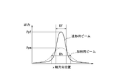
- FIG. 2 is a graph schematically showing an example of the profile shape of the modeling beam and the heating beam irradiated onto the powder bed by the modeling apparatus 1 of FIG.
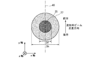
- FIG. 3 is a diagram schematically showing the beam shapes of the modeling beam and the heating beam having the profile shape of FIG. 2 in the powder bed.
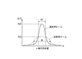
- FIG. 4 is a graph schematically showing an example of profile shapes of the modeling beam and the heating beam irradiated on the powder bed by the modeling apparatus 1 in FIG. 1.
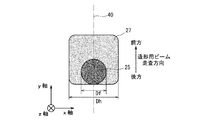
- FIG. 5 is a diagram schematically showing the beam shape of the modeling beam and the heating beam having the profile shape of FIG.
- FIG. 6 is a diagram schematically showing the beam shape of the modeling beam and the heating beam having the profile shape of FIG. 4 in the powder bed, and the irradiation position of the modeling beam is in the scanning direction of the modeling beam. It is a figure which shows the state located behind the center of the irradiation position of the heating beam.
- FIG. 7 is a diagram schematically showing the beam shape of the modeling beam and the heating beam having the profile shape of FIG. 4 in the powder bed, and the irradiation position of the modeling beam is in the scanning direction of the modeling beam.
- FIG. 8 is a diagram schematically showing the beam shape of the modeling beam having the profile shape of FIG. 4 together with a part of the wavy trajectory of the heating beam, in the scanning direction of the modeling beam. It is a figure which shows the state where the difference of the irradiation position of this and the irradiation position of the beam for a heating is small.
- FIG. 9 is a diagram schematically showing the beam shape of the modeling beam having the profile shape of FIG.
- FIG. 10 is a diagram schematically showing the beam shape of the modeling beam having the profile shape of FIG. 4 together with a part of the wavy trajectory of the heating beam, and in the scanning direction of the modeling beam, It is a figure which shows the state which is located ahead of the irradiation position of a heating beam.
- the modeling apparatus 1 can produce a modeled object made of metal or a modeled object made of nonmetal (for example, ABS resin, nylon, polyester, or carbon). For example, it can be used for products such as gas turbines, rocket engines, and turbochargers. The parts used can be produced. More specifically, the modeling apparatus 1 includes an axial-flow turbine and a centrifugal turbine gas turbine rotor blade, a gas turbine split ring, a gas turbine stationary blade, a centrifugal compressor impeller, a gas turbine combustor, and a gas turbine Compressors, rocket engine valves, etc. can be manufactured.
- a centrifugal turbine gas turbine rotor blade a gas turbine split ring, a gas turbine stationary blade, a centrifugal compressor impeller, a gas turbine combustor, and a gas turbine Compressors, rocket engine valves, etc.
- the modeling apparatus 1 includes a housing 3, a frame 5, a base plate 7, a powder bed forming unit 9, a modeling beam irradiation unit 11, a heating beam irradiation unit 13, and a control.
- a housing 3 As shown in FIG. 1, the modeling apparatus 1 includes a housing 3, a frame 5, a base plate 7, a powder bed forming unit 9, a modeling beam irradiation unit 11, a heating beam irradiation unit 13, and a control.
- a control. Device 15 the modeling apparatus 1 includes a housing 3, a frame 5, a base plate 7, a powder bed forming unit 9, a modeling beam irradiation unit 11, a heating beam irradiation unit 13, and a control.
- Device 15 As shown in FIG. 1, the modeling apparatus 1 includes a housing 3, a frame 5, a base plate 7, a powder bed forming unit 9, a modeling beam irradiation unit 11, a heating beam irradiation unit 13, and a control.
- the housing 3 is airtight as necessary, and the inside of the housing 3 can be evacuated or filled with an inert gas such as Ar gas.
- the frame 5 is disposed in the housing 3.
- the frame 5 has, for example, a rectangular tube shape, and the upper end of the frame 5 is open.
- the base plate 7 is disposed in the frame 5 so as to be movable in the vertical direction (z-axis direction), that is, to be movable up and down.
- the base plate 7 extends in the horizontal direction (x-axis direction and y-axis direction), and the periphery of the base plate 7 can be slidably contacted with the inner wall of the frame 5.
- the powder bed forming unit 9 can form the powder bed 17 on the base plate 7.
- the powder bed 17 is obtained by depositing powder, which is a raw material of a target modeled object, in a layered manner with a predetermined thickness.
- the powder bed forming unit 9 includes a horizontal table 19 disposed so as to sandwich the upper end opening of the frame body 5, a roller 21 that can travel horizontally on the horizontal table 19 and the upper end opening of the frame body 5, A hopper 23 capable of supplying raw material powder is provided on the table 19.
- the powder on the horizontal table 19 is carried to the upper end opening of the frame body 5 by the roller 21, and is flattened.
- a powder bed 17 can be formed inside the upper end.
- the configuration of the powder bed forming unit is not limited to this.
- Powder is supplied into the frame body 5 from a hopper movable in the horizontal direction, and the supplied powder is flattened to form the powder bed 17. Also good.
- the powder bed forming unit may have a powder tank disposed on the side of the frame 5 in a flush manner. In this case, by pushing up the bottom of the powder tank, the powder in the powder tank is pushed upward, and the pushed powder is carried into the frame 5 by a roller or the like and flattened to form the powder bed 17.
- the modeling beam irradiation unit 11 can irradiate the powder bed 17 with the modeling beam 25. In the region irradiated with the modeling beam 25, the particles constituting the powder bed 17 adhere to each other (sinter or melt and solidify) to constitute a part of the modeled article.
- the heating beam irradiation unit 13 can irradiate the powder bed 17 with a heating beam 27 having a lower output than the modeling beam 25.
- the heating beam irradiation unit 13 only needs to be able to irradiate the heating beam 27 having a lower output than the modeling beam 25, and the heating beam irradiation unit 13 is the same as the modeling beam irradiation unit 11. May be.
- the control device 15 can control the modeling beam irradiation unit 11 and the heating beam irradiation unit 13.
- the control device 15 can be configured by, for example, a computer having a CPU (Central Processing Unit), a memory, an external storage device, and an input / output unit. Then, the control device 15 causes the modeling beam irradiation unit 11 to irradiate the modeling beam 25 along the setting route corresponding to the shape of the target modeling object to the powder bed 17. 11 is configured to be controllable. Further, the control device 15 is configured to be able to control the modeling beam irradiation unit 11 so that the heating beam irradiation unit 13 irradiates the powder bed 17 with the heating beam 27 along the set route. .
- a computer having a CPU (Central Processing Unit), a memory, an external storage device, and an input / output unit.
- the control device 15 causes the modeling beam irradiation unit 11 to irradiate the modeling beam 25 along the setting route corresponding to the shape of the target modeling
- the modeling beam 25 and the heating beam 27 having a lower output than the modeling beam 25 can be irradiated to the powder bed 17 along the set route. Can be locally heated by the heating beam 27. For this reason, since the particles of the powder bed 17 are prevented from adhering to each other in an undesired region, the powder in the model is easily removed even when a model having a complicated internal structure is produced. be able to.
- the region irradiated with the modeling beam 25 can be heated by the heating beam 27, the residual stress of the modeled object can be reduced and the generation of cracks and voids in the modeled product can be suppressed. It is possible to produce a high-quality shaped object.
- the region irradiated with the modeling beam 25 may be a region irradiated with the modeling beam 25, may be a region scheduled to be irradiated with the modeling beam 25, or may be modeled.
- region where the beam 25 for irradiation was already irradiated may be sufficient.
- the output of the heating beam 27 being lower than the output of the modeling beam 25 means that the average output (integrated intensity per unit time) of the heating beam 27 is lower than the average output of the modeling beam 25. To do.
- the control device 15 is configured to change the profile shape of the heating beam 27 on the powder bed 17.
- the powder bed 17 can be locally heated by the heating beam 27 under various conditions by changing the profile shape of the heating beam 27. For this reason, according to the said structure, while being able to reduce the residual stress of a molded article reliably, the high quality molded article which has a complicated internal structure can be produced reliably.
- the profile shape of the heating beam 27 refers to the position on the powder bed 17 in the horizontal plane (for example, in the x-axis direction) and the output of the heating beam 27 when the heating beam 27 is not scanned. This represents the relationship.
- the heating beam irradiation unit 13 includes a heating beam source 29, a heating beam adjustment unit 31, and a heating beam scanning unit 33.
- the heating beam source 29 can emit the heating beam 27.
- the heating beam adjusting unit 31 can adjust the output and shape of the heating beam 27 emitted from the heating beam source 29.
- the heating beam scanning unit 33 can adjust the irradiation position of the heating beam 27.
- the control device 15 can change the profile shape of the heating beam 27 by controlling the heating beam adjusting unit 31.
- the output of the heating beam 27 may be adjustable by controlling the heating beam source 29.
- the modeling beam irradiation unit 11 may include a modeling beam source 35, a modeling beam adjustment unit 37, and a modeling beam scanning unit 39.
- the modeling beam source 35 can emit the modeling beam 25.
- the modeling beam adjusting unit 37 can adjust the output and profile shape of the modeling beam 25 emitted from the modeling beam source 35.
- the modeling beam scanning unit 39 can adjust the irradiation position of the modeling beam 25.
- the output and profile shape of the modeling beam 25 are set to an output and profile shape suitable for modeling. Note that the output of the modeling beam 25 may be adjustable by controlling the modeling beam source 35.
- the control device 15 uses the heating device 27 so that the beam diameter Dh of the heating beam 27 is larger than the beam diameter Df of the modeling beam 25.
- the profile shape of the beam 27 can be adjusted. 3 and 5 to 10, the alternate long and short dash line indicates the setting route 40 for the modeling beam 25.
- the setting route 40 is a route through which the modeling beam 25 should pass in the powder bed 17.
- control device 15 causes the profile shape of the modeling beam 25 to have the highest output at the center of the modeling beam 25 as shown in FIGS. Can be adjusted to a shape such as a Gaussian distribution shape. In this case, as shown in FIGS. 3 and 5 to 10, the beam shape of the modeling beam 25 on the powder bed 17 is circular.
- the beam shape is a line shape connecting points on the powder bed 17 where the beam output is half of the maximum value when the powder bed 17 is irradiated with the beam without scanning the beam.
- the beam diameter is the diameter of the circle (that is, the half width of the output) when the beam shape is circular, and is the length of the minor axis of the ellipse when the beam shape is elliptical. In the case where the shape is a rectangular shape, the shorter one of the two opposing sides is assumed to be the same.
- the control device 15 causes the profile of the heating beam 27 to have the highest output at the center of the heating beam 27 as shown in FIG. 2, and the output decreases as the distance from the center increases.
- a shape for example, a Gaussian distribution shape can be adjusted.
- the beam shape of the heating beam 27 on the powder bed 17 is circular.
- the controller 15 causes the profile shape of the heating beam 27 to have a constant output at the central portion of the heating beam 27 as shown in FIG.
- the plateau shape can be adjusted to be lower.
- the beam shape of the heating beam 27 on the powder bed 17 is a rectangular shape.
- control device 15 is configured to be able to change the relative positional relationship between the irradiation position of the modeling beam 25 and the irradiation position of the heating beam 27 in the powder bed 17.
- the powder bed 17 can be heated on the powder bed 17 under various conditions by changing the relative positional relationship between the irradiation position of the modeling beam 25 and the irradiation position of the heating beam 27 on the powder bed 17.
- 27 can be locally heated.
- control device 15 changes the relative positional relationship between the irradiation position of the modeling beam 25 and the irradiation position of the heating beam 27 in the powder bed 17 by controlling the heating beam scanning unit 33.
- the modeling beam 25 is scanned under conditions suitable for modeling. Therefore, by controlling the scanning of the heating beam 27, the irradiation position of the modeling beam 25 and the irradiation position of the heating beam 27 are determined. The relative positional relationship between is changed.
- the irradiation position of the modeling beam 25 is a position where the modeling beam 25 is applied on the powder bed 17, and the irradiation position of the heating beam 27 is the irradiation position of the heating beam 27 on the powder bed 17. It is a position. Changing the relative positional relationship between the irradiation position of the modeling beam 25 and the irradiation position of the heating beam 27 means the timing of irradiating the modeling beam 25 to any one point on the powder bed 17. That is, the timing of irradiating the heating beam 27 is changed.
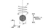
- the control device 15 controls the heating beam irradiation unit 13 so that the heating beam 27 is set to the setting route 40 in the powder bed 17. It is configured to be able to scan in a wave shape that travels along.
- the control device 15 since the control device 15 is configured to be able to scan the heating beam 27 in a wave shape that travels along the setting route 40, the region irradiated with the modeling beam 25 and its periphery are irradiated.
- the heating beam 27 can be sufficiently heated without being concentrated. For this reason, according to the said structure, while being able to reduce the residual stress of a molded article reliably, the high quality molded article which has a complicated internal structure can be produced reliably. 8 to 10 schematically show a part of the wavy locus 42 of the heating beam 27 as well as the beam shape of the modeling beam 25 on the powder bed 17.
- control device 15 controls the modeling beam irradiation unit 11 and the heating beam irradiation unit 13, thereby forming the modeling beam on the powder bed 17.
- 25 is configured to be positioned at the center of the irradiation position of the heating beam 27 in the scanning direction of the modeling beam 25.
- control device 15 controls the modeling beam irradiation unit 11 and the heating beam irradiation unit 13 to scan the heating beam 27 in a wave shape. Under the condition, the irradiation position of the heating beam 27 on the powder bed 17 can be overlapped with the irradiation position of the modeling beam 25.
- control device 15 controls the modeling beam irradiation unit 11 and the heating beam irradiation unit 13, thereby forming the modeling beam on the powder bed 17.
- the irradiation position 25 can be positioned behind the center of the irradiation position of the heating beam 27 in the scanning direction of the modeling beam 25.
- control device 15 controls the modeling beam irradiation unit 11 and the heating beam irradiation unit 13 to irradiate the modeling beam 25 on the powder bed 17.
- the position is configured so as to be positioned rearward from the irradiation position of the heating beam 27 in the scanning direction of the modeling beam 25.
- the control device 15 controls the modeling beam irradiation unit 11 and the heating beam irradiation unit 13, thereby forming the modeling beam on the powder bed 17.
- the irradiation position 25 can be positioned in front of the center of the irradiation position of the heating beam 27 in the scanning direction of the modeling beam 25.
- control device 15 controls the modeling beam irradiation unit 11 and the heating beam irradiation unit 13 to irradiate the modeling beam 25 on the powder bed 17.
- the position is configured so as to be positioned away from the irradiation position of the heating beam 27 in the scanning direction of the modeling beam 25.
- the control device 15 allows the beam diameter Dh of the heating beam 27 to be larger than the beam diameter Df of the modeling beam 25.
- the profile shape of the heating beam 27 can be adjusted, and the region irradiated with the modeling beam 25 can be superimposed on the region irradiated with the heating beam 27.
- the control device 15 uses the heating device 27 so that the beam diameter Dh of the heating beam 27 is larger than the beam diameter Df of the modeling beam 25.
- the profile shape of the beam 27 can be adjusted, the region irradiated with the modeling beam 25 can be positioned in the region irradiated with the heating beam 27, and the irradiation position of the modeling beam 25 Can be made to coincide with the center of the heating beam 27 in the scanning direction of the modeling beam 25.
- the control device 15 causes the heating beam 27 to have a beam diameter Dh larger than the beam diameter Df of the modeling beam 25.
- the profile shape can be adjusted, and the region irradiated with the modeling beam 25 can be positioned within the region irradiated with the heating beam 27. In the scanning direction of the heating beam 25, the heating beam 27 can be positioned behind the center.
- the control device 15 causes the heating beam 27 to have a beam diameter Dh of the heating beam 27 larger than the beam diameter Df of the modeling beam 25.
- the profile shape can be adjusted, and the region irradiated with the modeling beam 25 can be positioned within the region irradiated with the heating beam 27.
- the heating beam 27 can be positioned in front of the center of the heating beam 27.
- the modeling beam irradiation unit 11 also serves as the heating beam irradiation unit 13.
- the control device 15 is configured to cause the modeling beam irradiation unit 11 to irradiate the modeling beam 25 and the heating beam 27 at different timings. In this case, an independent heating beam irradiation unit 13 is unnecessary.
- the modeling beam irradiation unit 11 also serves as the heating beam irradiation unit 13, it is possible to reduce the residual stress of the modeled object with a simple configuration and to have a high quality having a complicated internal structure. Can be produced.
- the controller 15 may determine the powder depending on at least one of the scanning direction of the shaping beam 25, the material comprising the powder bed 17, the time to be preheated by the heating beam 27, and the like.
- the relative positional relationship between the irradiation position of the modeling beam 25 and the irradiation position of the heating beam 27 on the bed 17, the profile shape of the heating beam 27 on the powder bed 17, and the heating in the powder bed 17 At least one of the scanning directions of the beam 27 can be changed.
- the material constituting the powder bed 17 for the modeling in the powder bed 17 according to at least one of the scanning direction of the modeling beam 25, the material constituting the powder bed 17, the time to be preheated by the heating beam 27, and the like.
- the relative positional relationship between the irradiation position of the beam 25 and the irradiation position of the heating beam 27, the profile shape of the heating beam 27 on the powder bed 17, and the heating beam 27 on the powder bed 17 By changing at least one of the scanning directions, it is possible to reduce the residual stress of the modeled object while performing the minimum necessary preheating, and to produce a high-quality modeled object having a complicated internal structure. .
- the modeling beam 25 and the heating beam 27 are electron beams.
- the modeling beam source 35 and the heating beam source 29 are constituted by electron guns.
- the modeling beam adjusting unit 37 and the heating beam adjusting unit 31 are configured by an electromagnetic lens or the like, and the modeling beam scanning unit 39 and the heating beam scanning unit 33 are configured by a deflection coil or the like.
- the modeling beam 25 and the heating beam 27 are laser beams.
- the modeling beam source 35 and the heating beam source 29 are configured by a solid-state laser such as a YAG laser, a gas laser such as a CO 2 laser, or a semiconductor laser.
- the modeling beam adjustment unit 37 and the heating beam adjustment unit 31 are configured by an optical element such as an optical lens, and the modeling beam scanning unit 39 and the heating beam scanning unit 33 are configured by a galvanometer mirror or the like.
- the modeling beam 25 and the heating beam 27 are laser beams, and the modeling beam scanning unit 39 and the heating beam scanning unit 33 share one galvanometer mirror.
- the laser beam is, for example, visible light or infrared light.
- the wavelength of the modeling beam 25 and the wavelength of the heating beam 27 are the same.
- the wavelength of the modeling beam 25 and the wavelength of the heating beam 27 are different from each other.
- the shaping beam 25 is a continuous wave and the heating beam 27 is a pulsed wave.
- one of the modeling beam 25 and the heating beam 27 is an electron beam and the other is a laser beam.
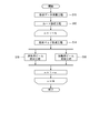
- FIG. 11 is a flowchart showing a schematic procedure of a selective beam layered modeling method (hereinafter also simply referred to as a modeling method) according to an embodiment of the present invention.
- the modeling method shown in FIG. 11 can be implemented using, for example, the modeling apparatus 1 shown in FIG.
- the modeling method includes a shape data preparation step S10, a route setting step S12, a powder bed forming step S14, a modeling beam irradiation step S16, and a heating beam irradiation step S18.
- shape data preparation step S10 data (shape data) relating to the shape of the target object is prepared.
- the shape data is, for example, three-dimensional CAD data.
- the prepared shape data is input to the control device 15.
- a route (setting route 40) for irradiating the modeling beam 25 to each of the plurality of layers of the powder bed 17 is determined based on the shape data.
- the setting route 40 can be automatically determined by, for example, the control device 15 executing a program prepared in advance.
- the powder bed 17 is formed on the base plate 7 arranged in the frame 5 so as to be movable up and down.
- the formation of the powder bed 17 can be performed by the powder bed forming unit 9.
- the control device 15 may control the powder bed forming unit 9 to form the powder bed 17.
- the modeling beam 25 is irradiated to the powder bed 17 along the setting route 40 corresponding to the shape of the target modeled object.
- the heating beam irradiation step S ⁇ b> 18 the powder bed 17 is irradiated with the heating beam 27 having a lower output than the modeling beam 25 along the setting route 40. Then, by repeating the powder bed forming step S14, the modeling beam irradiation step S16, and the heating beam irradiation step S18 while lowering the base plate 7 stepwise, a target modeled object can be manufactured. it can.
- the modeling beam 25 and the heating beam 27 having a lower output than the modeling beam 25 are irradiated along the setting route 40 to the powder bed 17. Can be locally heated by the heating beam 27. For this reason, since the particles of the powder bed 17 are prevented from adhering to each other in an undesired region, the powder in the model is easily removed even when a model having a complicated internal structure is produced. be able to.
- the region irradiated with the modeling beam 25 can be heated by the heating beam 27, the residual stress of the modeled object can be reduced and the generation of cracks and voids in the modeled product can be suppressed. It is possible to produce a high-quality shaped object.
- the region irradiated with the modeling beam 25 may be a region irradiated with the modeling beam 25, may be a region scheduled to be irradiated with the modeling beam 25, or may be modeled.
- region where the beam 25 for irradiation was already irradiated may be sufficient.
- the output of the heating beam 27 being lower than the output of the modeling beam 25 means that the average output (integrated intensity per unit time) of the heating beam 27 is lower than the average output of the modeling beam 25. To do.
- the heating beam 27 having a circular or rectangular beam shape is irradiated.
- the heating beam 27 having a circular or rectangular beam shape by irradiating the heating beam 27 having a circular or rectangular beam shape, the residual stress of the modeled object can be reduced, and a high-quality modeled object having a complicated internal structure can be obtained. It can be produced.
- the heating beam 27 having a beam diameter larger than the beam diameter Df of the modeling beam 25 is irradiated in the heating beam irradiation step S18.
- the region irradiated with the modeling beam 25 and its periphery are irradiated by the heating beam 27. Can be heated.
- the high quality molded article which has a complicated internal structure is producible.
- the heating beam 27 is scanned in a wave shape while scanning in a wave shape traveling along the setting route 40, and heating is performed.
- the beam diameter Dh of the working beam 27 is the same as or smaller than the beam diameter Df of the modeling beam 25. According to the above configuration, even if the beam diameter Dh of the heating beam 27 is equal to or smaller than the beam diameter Df of the modeling beam 25, the region irradiated with the modeling beam 25 by scanning the heating beam 27 in a wave shape. And the periphery thereof can be heated by the heating beam 27.
- the beam diameter Dh of the heating beam 27 may be larger than the beam diameter Df of the modeling beam 25. 8 to 10, the beam shape of the heating beam 27 is not shown, and only a part of the locus 42 of the heating beam 27 is shown.
- the heating beam 27 is scanned while scanning the powder bed 17 in a wave shape traveling along the set route 40. Irradiate.
- the heating beam 27 is scanned in a wave shape that travels along the setting route 40, the region irradiated with the modeling beam 25 and its periphery can be sufficiently obtained without concentrating the heating beam 27. Can be heated.
- the said structure while being able to reduce the residual stress of a molded article reliably, the high quality molded article which has a complicated internal structure can be produced reliably.
- “scanning in a wavy shape” means not only scanning in a sine wave shape, but also scanning in a rectangular wave shape, scanning in a triangular wave shape, or zigzag shape. This includes cases where scanning is performed.
- the heating beam 27 is scanned along the set route 40 over the set route 40, and the scan speed of the heating beam 27 is the same as the scan speed of the modeling beam 25. .
- the beam diameter Dh of the heating beam 27 is larger than the beam diameter Df of the modeling beam 25, and the powder The heating beam 27 is irradiated so that the irradiation position of the modeling beam 25 on the bed 17 is positioned at the center of the irradiation position of the heating beam 27 in the scanning direction of the modeling beam 25.
- the heating beam 27 is placed so that the irradiation position of the modeling beam 25 on the powder bed 17 is positioned at the center of the irradiation position of the heating beam 27 in the scanning direction of the modeling beam 25. Since irradiation is performed, the region to be irradiated with the modeling beam 25 can be preliminarily heated by the heating beam 27, and the region already irradiated with the modeling beam 25 can be heated later. For this reason, at an arbitrary point on the setting route 40, a rapid temperature increase and a rapid temperature decrease before and after the irradiation of the modeling beam 25 are prevented. As a result, according to the above configuration, the residual stress of the modeled object can be reliably reduced, and a high-quality modeled object having a complicated internal structure can be reliably manufactured.
- the irradiation position of the heating beam 27 on the powder bed 17 is determined for modeling while scanning the heating beam 27 in a wave shape. It overlaps with the irradiation position of the beam 25.
- the irradiation position of the modeling beam 25 on the powder bed 17 is in the scanning direction of the modeling beam 25.
- the heating beam 27 is irradiated so as to be positioned behind the center of the irradiation position of the heating beam 27.
- the heating beam is such that the irradiation position of the modeling beam 25 on the powder bed 17 is located behind the center of the irradiation position of the heating beam 27 in the scanning direction of the modeling beam 25. 27 is irradiated, the region to be irradiated with the modeling beam 25 can be preheated by the heating beam 27. For this reason, at an arbitrary point on the setting route 40, a rapid temperature increase before and after the irradiation of the modeling beam 25 is prevented. As a result, according to the above configuration, the residual stress of the modeled object can be reliably reduced, and a high-quality modeled object having a complicated internal structure can be reliably manufactured.
- the heating beam 27 is irradiated so as to be positioned rearward from the irradiation position of the heating beam 27.
- the irradiation position of the modeling beam 25 on the powder bed 17 is in the scanning direction of the modeling beam 25.
- the heating beam 27 is irradiated so as to be positioned in front of the center of the irradiation position of the heating beam 27.
- the heating beam is so positioned that the irradiation position of the modeling beam 25 on the powder bed 17 is positioned in front of the center of the irradiation position of the heating beam 27 in the scanning direction of the modeling beam 25. 27, the heating beam 27 can later heat the region that has already been irradiated with the modeling beam 25. For this reason, at an arbitrary point on the setting route 40, a rapid temperature drop before and after the irradiation of the modeling beam 25 is prevented. As a result, according to the above configuration, the residual stress of the modeled object can be reliably reduced, and a high-quality modeled object having a complicated internal structure can be reliably manufactured.
- the heating beam 27 is irradiated so as to be positioned away from the irradiation position of the heating beam 27.
- the beam diameter Dh of the heating beam 27 is larger than the beam diameter Df of the modeling beam 25 as shown in FIGS.
- the profile shape of the heating beam 27 is adjusted, the region irradiated with the modeling beam 25 is positioned in the region irradiated with the heating beam 27, and the irradiation position of the modeling beam 25 is In the scanning direction of the modeling beam 25, it is made to coincide with the center of the heating beam 27.
- the heating beam 27 has a heating beam 27 so that the beam diameter Dh of the heating beam 27 is larger than the beam diameter Df of the modeling beam 25.
- the profile shape of the beam 27 is adjusted, the region irradiated with the modeling beam 25 is positioned in the region irradiated with the heating beam 27, and the irradiation position of the modeling beam 25 is set as the modeling beam. It is positioned behind the center of the heating beam 27 in 25 scanning directions.
- the heating beam 27 has a beam diameter Dh larger than the beam diameter Df of the modeling beam 25, as shown in FIG.
- the profile shape of the beam 27 is adjusted, the region irradiated with the modeling beam 25 is positioned in the region irradiated with the heating beam 27, and the irradiation position of the modeling beam 25 is set as the modeling beam. In the scanning direction of 25, it is positioned ahead of the center of the heating beam 27.
- the heating beam irradiation step S18 at least one of the scanning direction of the modeling beam 25, the material constituting the powder bed 17, the time to be preheated by the heating beam 27, and the like is determined.
- the relative positional relationship between the irradiation position of the modeling beam 25 on the powder bed 17 and the irradiation position of the heating beam 27, the profile shape of the heating beam 27 on the powder bed 17, and the powder bed At least one of the scanning directions of the heating beam 27 on 17 is changed.
- the material constituting the powder bed 17 for the modeling in the powder bed 17 according to at least one of the scanning direction of the modeling beam 25, the material constituting the powder bed 17, the time to be preheated by the heating beam 27, and the like.
- the relative positional relationship between the irradiation position of the beam 25 and the irradiation position of the heating beam 27, the profile shape of the heating beam 27 on the powder bed 17, and the heating beam 27 on the powder bed 17 By changing at least one of the scanning directions, it is possible to reduce the residual stress of the modeled object while performing the minimum necessary preheating, and to produce a high-quality modeled object having a complicated internal structure. .
- the present invention is not limited to the above-described embodiments, and includes forms obtained by changing the above-described embodiments and forms obtained by combining these forms.
- the modeling apparatus 1 and the modeling method described above are suitable for manufacturing a modeled object having a complicated internal structure, the modeling apparatus 1 and the modeling method are also applicable to manufacturing a modeled object having a simple internal structure.
- the modeled object produced by the modeling apparatus 1 and the modeling method described above is not limited to the above-described product parts.
Landscapes
- Engineering & Computer Science (AREA)
- Chemical & Material Sciences (AREA)
- Materials Engineering (AREA)
- Manufacturing & Machinery (AREA)
- Physics & Mathematics (AREA)
- Optics & Photonics (AREA)
- Mechanical Engineering (AREA)
- Automation & Control Theory (AREA)
- Plasma & Fusion (AREA)
- Health & Medical Sciences (AREA)
- Toxicology (AREA)
- Microelectronics & Electronic Packaging (AREA)
- Powder Metallurgy (AREA)
- Heating, Cooling, Or Curing Plastics Or The Like In General (AREA)
Priority Applications (3)
| Application Number | Priority Date | Filing Date | Title |
|---|---|---|---|
| CN201780033910.1A CN109311227B (zh) | 2016-06-07 | 2017-06-05 | 选择型射束层叠造型装置及选择型射束层叠造型方法 |
| EP17810258.8A EP3466647A4 (en) | 2016-06-07 | 2017-06-05 | DEVICE FOR SELECTIVE BEAM MELTING AND METHOD FOR SELECTIVE BEAM MELTING |
| US16/306,771 US20190193329A1 (en) | 2016-06-07 | 2017-06-05 | Selective beam additive manufacturing device and selective beam additive manufacturing method |
Applications Claiming Priority (2)
| Application Number | Priority Date | Filing Date | Title |
|---|---|---|---|
| JP2016-113174 | 2016-06-07 | ||
| JP2016113174A JP6600278B2 (ja) | 2016-06-07 | 2016-06-07 | 選択型ビーム積層造形装置及び選択型ビーム積層造形方法 |
Publications (1)
| Publication Number | Publication Date |
|---|---|
| WO2017213082A1 true WO2017213082A1 (ja) | 2017-12-14 |
Family
ID=60579000
Family Applications (1)
| Application Number | Title | Priority Date | Filing Date |
|---|---|---|---|
| PCT/JP2017/020821 Ceased WO2017213082A1 (ja) | 2016-06-07 | 2017-06-05 | 選択型ビーム積層造形装置及び選択型ビーム積層造形方法 |
Country Status (5)
| Country | Link |
|---|---|
| US (1) | US20190193329A1 (enExample) |
| EP (1) | EP3466647A4 (enExample) |
| JP (1) | JP6600278B2 (enExample) |
| CN (1) | CN109311227B (enExample) |
| WO (1) | WO2017213082A1 (enExample) |
Cited By (1)
| Publication number | Priority date | Publication date | Assignee | Title |
|---|---|---|---|---|
| WO2019189623A1 (ja) * | 2018-03-30 | 2019-10-03 | 株式会社フジクラ | 照射装置、金属造形装置、金属造形システム、照射方法、及び金属造形物の製造方法 |
Families Citing this family (10)
| Publication number | Priority date | Publication date | Assignee | Title |
|---|---|---|---|---|
| US11207827B2 (en) * | 2017-03-29 | 2021-12-28 | Hewlett-Packard Development Company, L.P. | Energy dosing for additive manufacturing |
| JP6534470B1 (ja) * | 2018-03-30 | 2019-06-26 | 株式会社フジクラ | 照射装置、金属造形装置、金属造形システム、照射方法、及び金属造形物の製造方法 |
| US11858202B2 (en) * | 2019-03-26 | 2024-01-02 | Lawrence Livermore National Security, Llc | System and method for performing laser powder bed fusion using controlled, supplemental in situ surface heating to control microstructure and residual stresses in formed part |
| WO2020249619A1 (en) | 2019-06-13 | 2020-12-17 | SLM Solutions Group AG | Apparatus and method for producing a three-dimensional work piece |
| JP2021188070A (ja) * | 2020-05-27 | 2021-12-13 | 三菱重工業株式会社 | 積層造形方法及び積層造形装置 |
| JP7600547B2 (ja) * | 2020-06-04 | 2024-12-17 | 株式会社ジェイテクト | 付加製造装置 |
| KR102562792B1 (ko) * | 2020-09-07 | 2023-08-03 | 이광민 | 3d 조형물과 시트필름을 분리하는 장치 및 이를 포함하는 3d 프린터 |
| JP7729037B2 (ja) * | 2020-12-23 | 2025-08-26 | 株式会社ジェイテクト | 付加製造装置 |
| JP7714887B2 (ja) * | 2021-02-25 | 2025-07-30 | 株式会社ジェイテクト | 付加製造装置 |
| JPWO2024024109A1 (enExample) * | 2022-07-29 | 2024-02-01 |
Citations (7)
| Publication number | Priority date | Publication date | Assignee | Title |
|---|---|---|---|---|
| JP2000517375A (ja) * | 1995-11-27 | 2000-12-26 | ボード・オブ・リージェンツ,ザ・ユニバーシティ・オブ・テキサス・システム | 熱間等圧処理を用いるレーザー指向物品製造法 |
| JP2002069507A (ja) * | 2000-09-01 | 2002-03-08 | Hitachi Ltd | 金属物品の製造方法及びその装置並びにレーザ光集光装置 |
| JP2005335392A (ja) | 2004-05-28 | 2005-12-08 | Three D Syst Inc | ウェーブ平坦化装置を用いた片側供給待機粉体ウェーブの加熱 |
| JP2015038237A (ja) * | 2013-08-19 | 2015-02-26 | 独立行政法人産業技術総合研究所 | 積層造形物、粉末積層造形装置及び粉末積層造形方法 |
| JP2015120340A (ja) * | 2013-11-27 | 2015-07-02 | エスエルエム ソルーションズ グループ アーゲー | 照射システムを制御する方法及び制御装置 |
| JP5826430B1 (ja) * | 2015-08-03 | 2015-12-02 | 株式会社松浦機械製作所 | 三次元造形装置及び三次元形状造形物の製造方法 |
| WO2016151740A1 (ja) * | 2015-03-23 | 2016-09-29 | 技術研究組合次世代3D積層造形技術総合開発機構 | レーザ加熱制御機構、レーザ加熱制御方法、レーザ加熱制御プログラムおよび3次元造形装置 |
Family Cites Families (13)
| Publication number | Priority date | Publication date | Assignee | Title |
|---|---|---|---|---|
| US5182056A (en) * | 1988-04-18 | 1993-01-26 | 3D Systems, Inc. | Stereolithography method and apparatus employing various penetration depths |
| DE102007024469B4 (de) * | 2007-05-25 | 2009-04-23 | Eos Gmbh Electro Optical Systems | Verfahren zum schichtweisen Herstellen eines dreidimensionalen Objekts |
| CN103038681B (zh) * | 2010-06-30 | 2016-09-28 | 3M创新有限公司 | 使用具有空间选择性双折射减小的膜的掩模加工 |
| CH705662A1 (de) * | 2011-11-04 | 2013-05-15 | Alstom Technology Ltd | Prozess zur Herstellung von Gegenständen aus einer durch Gamma-Prime-Ausscheidung verfestigten Superlegierung auf Nickelbasis durch selektives Laserschmelzen (SLM). |
| EP2893994B1 (en) * | 2014-01-14 | 2020-07-15 | General Electric Technology GmbH | Method for manufacturing a metallic or ceramic component by selective laser melting additive manufacturing |
| US9346127B2 (en) * | 2014-06-20 | 2016-05-24 | Velo3D, Inc. | Apparatuses, systems and methods for three-dimensional printing |
| CN107000321A (zh) * | 2014-10-01 | 2017-08-01 | 瑞尼斯豪公司 | 增材制造设备和方法 |
| GB201417687D0 (en) * | 2014-10-07 | 2014-11-19 | Renishaw Plc | A module for additive manufacturing apparatus |
| US20160318129A1 (en) * | 2015-05-01 | 2016-11-03 | General Electric Company | System and method for multi-laser additive manufacturing |
| EP3325192A4 (en) * | 2015-07-18 | 2019-05-08 | Vulcanforms Inc. | GENERATIVE MANUFACTURE THROUGH ROOM-CONTROLLED MATERIAL FUSION |
| CN105127424A (zh) * | 2015-09-24 | 2015-12-09 | 湖南华曙高科技有限责任公司 | 制造三维物体的装置及方法 |
| GB201600645D0 (en) * | 2016-01-13 | 2016-02-24 | Rolls Royce Plc | Improvements in additive layer manufacturing methods |
| JP6551275B2 (ja) * | 2016-03-18 | 2019-07-31 | 株式会社豊田中央研究所 | レーザ加工装置、三次元造形装置、及びレーザ加工方法 |
-
2016
- 2016-06-07 JP JP2016113174A patent/JP6600278B2/ja active Active
-
2017
- 2017-06-05 CN CN201780033910.1A patent/CN109311227B/zh not_active Expired - Fee Related
- 2017-06-05 WO PCT/JP2017/020821 patent/WO2017213082A1/ja not_active Ceased
- 2017-06-05 EP EP17810258.8A patent/EP3466647A4/en not_active Withdrawn
- 2017-06-05 US US16/306,771 patent/US20190193329A1/en not_active Abandoned
Patent Citations (7)
| Publication number | Priority date | Publication date | Assignee | Title |
|---|---|---|---|---|
| JP2000517375A (ja) * | 1995-11-27 | 2000-12-26 | ボード・オブ・リージェンツ,ザ・ユニバーシティ・オブ・テキサス・システム | 熱間等圧処理を用いるレーザー指向物品製造法 |
| JP2002069507A (ja) * | 2000-09-01 | 2002-03-08 | Hitachi Ltd | 金属物品の製造方法及びその装置並びにレーザ光集光装置 |
| JP2005335392A (ja) | 2004-05-28 | 2005-12-08 | Three D Syst Inc | ウェーブ平坦化装置を用いた片側供給待機粉体ウェーブの加熱 |
| JP2015038237A (ja) * | 2013-08-19 | 2015-02-26 | 独立行政法人産業技術総合研究所 | 積層造形物、粉末積層造形装置及び粉末積層造形方法 |
| JP2015120340A (ja) * | 2013-11-27 | 2015-07-02 | エスエルエム ソルーションズ グループ アーゲー | 照射システムを制御する方法及び制御装置 |
| WO2016151740A1 (ja) * | 2015-03-23 | 2016-09-29 | 技術研究組合次世代3D積層造形技術総合開発機構 | レーザ加熱制御機構、レーザ加熱制御方法、レーザ加熱制御プログラムおよび3次元造形装置 |
| JP5826430B1 (ja) * | 2015-08-03 | 2015-12-02 | 株式会社松浦機械製作所 | 三次元造形装置及び三次元形状造形物の製造方法 |
Non-Patent Citations (1)
| Title |
|---|
| See also references of EP3466647A4 |
Cited By (2)
| Publication number | Priority date | Publication date | Assignee | Title |
|---|---|---|---|---|
| WO2019189623A1 (ja) * | 2018-03-30 | 2019-10-03 | 株式会社フジクラ | 照射装置、金属造形装置、金属造形システム、照射方法、及び金属造形物の製造方法 |
| JP2019178410A (ja) * | 2018-03-30 | 2019-10-17 | 株式会社フジクラ | 照射装置、金属造形装置、金属造形システム、照射方法、及び金属造形物の製造方法 |
Also Published As
| Publication number | Publication date |
|---|---|
| JP6600278B2 (ja) | 2019-10-30 |
| EP3466647A4 (en) | 2020-01-22 |
| CN109311227A (zh) | 2019-02-05 |
| US20190193329A1 (en) | 2019-06-27 |
| EP3466647A1 (en) | 2019-04-10 |
| JP2017217799A (ja) | 2017-12-14 |
| CN109311227B (zh) | 2021-01-05 |
Similar Documents
| Publication | Publication Date | Title |
|---|---|---|
| JP6600278B2 (ja) | 選択型ビーム積層造形装置及び選択型ビーム積層造形方法 | |
| US10012088B2 (en) | Additive manufacturing system utilizing an epitaxy process and method of operation | |
| CN104972118B (zh) | 三维造型装置和三维形状造型物的制造方法 | |
| CN105026076B (zh) | 用于生产具有定制微观结构的工件的装置和方法 | |
| JP6030597B2 (ja) | 三次元造形装置及び三次元形状造形物の製造方法 | |
| US20170304895A1 (en) | Additive manufacturing apparatus and method | |
| US11117194B2 (en) | Additive manufacturing having energy beam and lamp array | |
| JP5826430B1 (ja) | 三次元造形装置及び三次元形状造形物の製造方法 | |
| US20210370448A1 (en) | Diode laser fiber array for contour of powder bed fabrication or repair | |
| US20220097174A1 (en) | Variable beam geometry laser-based powder bed fusion | |
| US11638955B2 (en) | Applying electric pulses through a laser induced plasma channel for use in a 3-D metal printing process | |
| CN104775116A (zh) | 以选择性激光熔化增材制造来制造金属或陶瓷构件的方法 | |
| CN110267796A (zh) | 增材制造系统及方法 | |
| CN114054770B (zh) | 用于金属合金的激光器粉末床融合处理的激光器阵列 | |
| US11396175B2 (en) | Method and device for producing a three-dimensional object | |
| JP2015085547A (ja) | 積層造形装置及び積層造形物の製造方法 | |
| US20170216971A1 (en) | Use of variable wavelength laser energy for custom additive manufacturing | |
| CN111278589B (zh) | 金属部件的制造方法 | |
| CN110621479A (zh) | 用于增材制造的不断变化的影线 | |
| JP2018095955A (ja) | 三次元的な物体を付加的に製造するための方法 | |
| US20190143407A1 (en) | Additive manufacturing apparatus and additive manufacturing method of shaped article | |
| WO2014207751A2 (en) | Method and device for selective laser sintering (sls) rapid prototype | |
| JP2023545689A (ja) | 偏光制御により3次元ワークピースを造形するための照射システムを動作させる方法、照射システム及び装置 | |
| JP2025164079A (ja) | 付加製造方法及び付加製造装置 |
Legal Events
| Date | Code | Title | Description |
|---|---|---|---|
| 121 | Ep: the epo has been informed by wipo that ep was designated in this application |
Ref document number: 17810258 Country of ref document: EP Kind code of ref document: A1 |
|
| NENP | Non-entry into the national phase |
Ref country code: DE |
|
| ENP | Entry into the national phase |
Ref document number: 2017810258 Country of ref document: EP Effective date: 20190107 |