WO2017212982A1 - ヒートシンク及び冷却器 - Google Patents
ヒートシンク及び冷却器 Download PDFInfo
- Publication number
- WO2017212982A1 WO2017212982A1 PCT/JP2017/020101 JP2017020101W WO2017212982A1 WO 2017212982 A1 WO2017212982 A1 WO 2017212982A1 JP 2017020101 W JP2017020101 W JP 2017020101W WO 2017212982 A1 WO2017212982 A1 WO 2017212982A1
- Authority
- WO
- WIPO (PCT)
- Prior art keywords
- heat sink
- carbon particles
- base plate
- particles
- carbon
- Prior art date
- Legal status (The legal status is an assumption and is not a legal conclusion. Google has not performed a legal analysis and makes no representation as to the accuracy of the status listed.)
- Ceased
Links
Images



Classifications
-
- H—ELECTRICITY
- H10—SEMICONDUCTOR DEVICES; ELECTRIC SOLID-STATE DEVICES NOT OTHERWISE PROVIDED FOR
- H10W—GENERIC PACKAGES, INTERCONNECTIONS, CONNECTORS OR OTHER CONSTRUCTIONAL DETAILS OF DEVICES COVERED BY CLASS H10
- H10W40/00—Arrangements for thermal protection or thermal control
- H10W40/20—Arrangements for cooling
- H10W40/25—Arrangements for cooling characterised by their materials
- H10W40/257—Arrangements for cooling characterised by their materials having a heterogeneous or anisotropic structure, e.g. powder or fibres in a matrix, wire mesh or porous structures
-
- B—PERFORMING OPERATIONS; TRANSPORTING
- B23—MACHINE TOOLS; METAL-WORKING NOT OTHERWISE PROVIDED FOR
- B23P—METAL-WORKING NOT OTHERWISE PROVIDED FOR; COMBINED OPERATIONS; UNIVERSAL MACHINE TOOLS
- B23P15/00—Making specific metal objects by operations not covered by a single other subclass or a group in this subclass
- B23P15/26—Making specific metal objects by operations not covered by a single other subclass or a group in this subclass heat exchangers or the like
-
- H—ELECTRICITY
- H05—ELECTRIC TECHNIQUES NOT OTHERWISE PROVIDED FOR
- H05K—PRINTED CIRCUITS; CASINGS OR CONSTRUCTIONAL DETAILS OF ELECTRIC APPARATUS; MANUFACTURE OF ASSEMBLAGES OF ELECTRICAL COMPONENTS
- H05K7/00—Constructional details common to different types of electric apparatus
- H05K7/20—Modifications to facilitate cooling, ventilating, or heating
-
- H—ELECTRICITY
- H10—SEMICONDUCTOR DEVICES; ELECTRIC SOLID-STATE DEVICES NOT OTHERWISE PROVIDED FOR
- H10W—GENERIC PACKAGES, INTERCONNECTIONS, CONNECTORS OR OTHER CONSTRUCTIONAL DETAILS OF DEVICES COVERED BY CLASS H10
- H10W40/00—Arrangements for thermal protection or thermal control
- H10W40/10—Arrangements for heating
-
- H—ELECTRICITY
- H10—SEMICONDUCTOR DEVICES; ELECTRIC SOLID-STATE DEVICES NOT OTHERWISE PROVIDED FOR
- H10W—GENERIC PACKAGES, INTERCONNECTIONS, CONNECTORS OR OTHER CONSTRUCTIONAL DETAILS OF DEVICES COVERED BY CLASS H10
- H10W40/00—Arrangements for thermal protection or thermal control
- H10W40/20—Arrangements for cooling
- H10W40/22—Arrangements for cooling characterised by their shape, e.g. having conical or cylindrical projections
- H10W40/226—Arrangements for cooling characterised by their shape, e.g. having conical or cylindrical projections characterised by projecting parts, e.g. fins to increase surface area
-
- H—ELECTRICITY
- H10—SEMICONDUCTOR DEVICES; ELECTRIC SOLID-STATE DEVICES NOT OTHERWISE PROVIDED FOR
- H10W—GENERIC PACKAGES, INTERCONNECTIONS, CONNECTORS OR OTHER CONSTRUCTIONAL DETAILS OF DEVICES COVERED BY CLASS H10
- H10W40/00—Arrangements for thermal protection or thermal control
- H10W40/20—Arrangements for cooling
- H10W40/25—Arrangements for cooling characterised by their materials
-
- H—ELECTRICITY
- H10—SEMICONDUCTOR DEVICES; ELECTRIC SOLID-STATE DEVICES NOT OTHERWISE PROVIDED FOR
- H10W—GENERIC PACKAGES, INTERCONNECTIONS, CONNECTORS OR OTHER CONSTRUCTIONAL DETAILS OF DEVICES COVERED BY CLASS H10
- H10W70/00—Package substrates; Interposers; Redistribution layers [RDL]
- H10W70/01—Manufacture or treatment
- H10W70/02—Manufacture or treatment of conductive package substrates serving as an interconnection, e.g. of metal plates
Definitions
- the present invention relates to a heat sink and a cooler for cooling a heating element such as a heat generating element, and a method for manufacturing the heat sink.
- an electronic element is mounted on a mounting surface of an insulating substrate by soldering.
- the insulating substrate is bonded to the cooling surface composed of one surface in the thickness direction of the base plate portion of the heat sink or the cooling surface of the cooler by brazing or the like in order to cool the heat generated electronic elements (for example, Patent Literature 1-4).
- Heat sinks and coolers are required to have high cooling performance (including heat dissipation performance) in order to reliably cool the generated electronic elements.
- the present invention has been made in view of the above-described technical background, and an object thereof is to provide a heat sink and a cooler having high cooling performance, and a method of manufacturing the heat sink. Other objects and advantages of the present invention will become apparent from the following preferred embodiments.
- the present invention provides the following means.
- a plurality of fin portions are integrally formed on the base plate portion so as to protrude from the base plate portion, A heat sink in which carbon particles existing in the fin portion are oriented in a protruding direction of the fin portion with respect to the base plate portion.
- a cooler provided with the heat sink described in 1 or 2 above.
- a method of manufacturing a heat sink wherein the heat sink according to 1 or 2 is formed by hot forging a forged material made of a composite material of aluminum and carbon particles.
- a method of manufacturing a heat sink wherein the heat sink according to item 2 is formed from an extruded mold obtained by extruding a billet made of a composite material of aluminum and carbon particles.
- the present invention has the following effects.
- the carbon particles present in the fin portion of the base plate portion of the heat sink are oriented in the protruding direction of the fin portion with respect to the base plate portion, the thermal conductivity in the protruding direction of the fin portion is increased. As a result, the heat sink has a high cooling performance.
- the scaly graphite particles are used as the carbon particles, whereby the cooling performance of the heat sink can be further enhanced.
- FIG. 1 is a cross-sectional view showing a heat sink according to a first embodiment of the present invention together with an insulating substrate.
- FIG. 2a is a perspective view of the heat sink.
- FIG. 2 b is a partially cutaway side view showing the extrusion apparatus in a state where the billet is being extruded.
- FIG. 3 is a cross-sectional view showing a cooler including the heat sink together with an insulating substrate.
- FIG. 4 is a perspective view of a heat sink according to the second embodiment of the present invention.
- FIG. 5 is a cross-sectional view showing a state in the middle of hot forging a forging material for forming the heat sink.
- FIG. 6 is a cross-sectional view of a heat sink according to the third embodiment of the present invention.
- FIG. 7 is a cross-sectional view of a heat sink according to the fourth embodiment of the present invention.
- FIG. 1 and 2 are diagrams for explaining a first embodiment of the present invention.
- the heat sink 1 ⁇ / b> A is a heat generating element (indicated by a two-dot chain line) as a heating element joined to the mounting surface 20 a of the insulating substrate 20 by soldering or the like.
- the heat generating element 25 is cooled by dissipating 25 heat.
- Specific examples of the heat-generating element 25 include electronic elements such as semiconductor elements.
- the insulating substrate 20 includes a wiring layer 21 having a mounting surface 20a, an electrical insulating layer 22 made of ceramic, a buffer layer 23 made of metal, and the like, and these layers 21, 22, and 23 are joined and integrated in a stacked manner.
- a DBA substrate or a DBC substrate is used.
- the heat sink 1A is made of a composite material of aluminum and carbon particles 5, and includes a base plate portion 2 and a large number of fin portions 3 for heat dissipation.
- the carbon particles 5 are anisotropic with respect to thermal conductivity.
- the carbon particles 5 are drawn in a short line shape.
- the linear direction (length direction) of the carbon particle 5 drawn in drawing shows the high heat conduction direction of the carbon particle 5. The same applies to other drawings.
- FIG. 1 hatching is omitted in the cross section of the heat sink 1 ⁇ / b> A for easy understanding of the direction of the carbon particles 5 existing in the heat sink 1 ⁇ / b> A (that is, the high heat conduction direction of the carbon particles 5).
- hatching is omitted in the cross section of the heat sink 1 ⁇ / b> A for easy understanding of the direction of the carbon particles 5 existing in the heat sink 1 ⁇ / b> A (that is, the high heat conduction direction of the carbon particles 5).
- hatching is omitted in the cross section of the heat sink 1 ⁇ / b> A for easy understanding of the direction of the carbon particles 5 existing in the heat sink 1 ⁇ / b> A (that is, the high heat conduction direction of the carbon particles 5).
- the large number of fin portions 3 are integrally formed with the base plate portion 2 so as to protrude from at least one side of both sides in the thickness direction with respect to the base plate portion 2.
- each fin part 3 is integrally formed in the base plate part 2 continuously in the length direction of the base plate part 2 (direction perpendicular to the paper surface of FIG. 1). Accordingly, each fin portion 3 is a so-called straight fin portion 3a.
- the insulating substrate 20 is joined by brazing or the like to the cooling surface 2a formed of the surface on the side where the large number of straight fin portions 3a are not provided among both surfaces in the thickness direction of the base plate portion 2.
- the cooling surface 2a of the base plate part 2 is formed in a substantially flat shape.
- Ni plating layer may be formed on the surface of the heat sink 1A in order to improve solderability and corrosion resistance before the insulating substrate 20 is bonded to the cooling surface 2a.
- the Ni plating layer may be formed by an electroless Ni plating method or an electric Ni plating method.
- the type of the carbon particles 5 is not limited, but has a high thermal conductivity as much as possible and is a composite of aluminum. Those that can be easily formed are desirable.
- the carbon particles 5 are desirably at least one selected from the group consisting of carbon fibers, carbon nanotubes, graphene, natural graphite particles and artificial graphite particles, and further, carbon fibers, carbon nanotubes, graphene and It is more desirable that it is at least one selected from the group consisting of natural graphite particles.
- carbon fiber pitch-based carbon fiber, PAN-based carbon fiber, or the like is preferably used.
- carbon nanotubes single-walled carbon nanotubes, multi-walled carbon nanotubes, vapor-grown carbon fibers (including VGCF (registered trademark)) and the like are preferably used.
- graphene single layer graphene, multilayer graphene, or the like is preferably used.
- artificial graphite particles anisotropic graphite particles, pyrolytic graphite particles and the like are preferably used.
- the size of the carbon particles 5 is not limited. However, when the carbon particles 5 are carbon fibers, short carbon fibers are preferably used, and in particular, short carbon fibers having an average fiber length of 10 ⁇ m to 2 mm are preferably used. When the carbon particles 5 are carbon nanotubes, carbon nanotubes having an average length of 1 ⁇ m or more and 10 ⁇ m or less are particularly preferably used. When the carbon particles 5 are natural graphite particles and artificial graphite particles, natural graphite particles and artificial graphite particles having an average particle diameter of 10 ⁇ m or more and 3 mm or less are particularly preferably used.
- the type of composite material of aluminum and carbon particles 5 is not limited.
- the composite material is obtained by sintering and integrating a plurality of coated foils obtained by coating a carbon particle layer on an aluminum foil in a laminated state (hereinafter referred to as “laminated sintered mold” for convenience of explanation.
- Composite material or aluminum particles (e.g., aluminum powder) and carbon particles (e.g., carbon powder) mixed and sintered (this composite material is referred to as " It may also be a particle-sintered composite ").
- aluminum is used as a matrix metal and carbon particles 5 are used as a filler. Many carbon particles 5 are dispersed in the aluminum throughout the composite material.
- the carbon particles 5 present in each straight fin portion 3a are oriented in the protruding direction P of the straight fin portion 3a with respect to the base plate portion 2, and accordingly, the carbon particles 5 present in each straight fin portion 3a
- the high heat conduction direction is oriented in the protruding direction P of the straight fin portion 3 a with respect to the base plate portion 2.
- carbon particles having good thermal conductivity in the surface direction of the particles are used as the carbon particles 5, that is, carbon particles whose direction of high thermal conductivity is the surface direction of the particles are used. Yes. Specifically, scaly graphite particles are used as such carbon particles 5.
- the thermal conductivity in the surface direction of the scaly graphite particles is much higher than the thermal conductivity in the thickness direction. Therefore, in this 1st Embodiment, the surface direction of the scale-like graphite particle which exists in each straight fin part 3a is orientated in the protrusion direction P of the straight fin part 3a, and, thereby, the scale in each straight fin part 3a The high heat conduction direction of the graphite particles is oriented in the protruding direction P of the straight fin portion 3a.
- the heat sink 1A of the first embodiment is formed of an extrusion mold material.
- the symbol “E” in FIG. 2 a indicates the extrusion direction of the extrusion mold material.
- the manufacturing method of the heat sink 1A of the first embodiment is as follows.
- a substantially cylindrical billet (that is, an extruded material) 45 made of a composite material of aluminum and scaly graphite particles as the carbon particles 5 is extruded by an extrusion apparatus 40, whereby a heat sink 1A is obtained.
- a long extruded mold member 46 having the same cross-sectional shape as the above-described cross-sectional shape is obtained.
- the billet 45 is provided with dot hatching so that the billet 45 can be easily distinguished from other members.
- the extrusion apparatus 40 includes a container 41, an extrusion die 42, a stem 44, and the like.
- the extrusion die 42 includes an extrusion hole 43 having the same cross-sectional shape as that of the heat sink 1A.
- the heat sink 1A formed of the extrusion mold 46 shown in FIG. 2a is obtained by cutting the extrusion mold 46 into a predetermined length.
- the continuous direction of the straight fin portions 3 a coincides with the extrusion direction E of the extrusion mold material 46.
- each straight fin portion 3a can be reliably oriented in the protruding direction P of the straight fin portion 3a, and the heat sink 1A having such a large number of straight fin portions 3a can be reliably and easily provided. Can be manufactured.
- the billet 45 may be composed of the above-described laminated sintered composite material, may be composed of the above-described particle sintered composite material, or other composite material of aluminum and carbon particles. It may consist of.
- the heat sink 1A of the first embodiment since the carbon particles 5 present in each straight fin portion 3a are oriented in the protruding direction P of the straight fin portion 3a with respect to the base plate portion 2, the straight fin portions 3a The thermal conductivity in the protruding direction P is high. Therefore, the heat sink 1A has high cooling performance (including heat dissipation performance).
- the heat sink 1A has a very high cooling performance.
- carbon particles 5 are not carbon particles in which the direction of high thermal conductivity is the surface direction of the particles, such as scaly graphite particles, carbon particles in which the direction of high thermal conductivity is only one direction of the particles.
- carbon fiber when a heat sink is formed with an extrusion mold material obtained by extruding a billet made of a composite material of aluminum and the carbon particles, the present in each straight fin portion There is a tendency that the carbon particles are less likely to be oriented in the protruding direction P of the straight fin portion.
- the heat sink when the heat sink is formed of an extrusion mold, it is particularly desirable to use carbon particles (for example, scaly graphite particles) having a high thermal conductivity direction of the particles as the carbon particles 5, and such carbon particles By using this, even when the heat sink is formed of an extrusion mold material, the carbon particles 5 can be reliably oriented in the protruding direction P of the straight fin portion 3a.
- carbon particles for example, scaly graphite particles
- FIG. 3 includes a heat sink 1A according to the first embodiment shown in FIGS. 1 and 2 and a housing body 11.
- the housing body 11 is made of metal, for example, and has an opening.
- the heat sink 1A is disposed in the housing body 11, the opening of the housing body 11 is closed by the base plate portion 2 of the heat sink 1A, and the inside of the housing body 11 is partitioned by a number of straight fin portions 3a of the heat sink 1A.
- a flow path 12 through which a cooling fluid (for example, a cooling liquid) flows is formed in the housing body 11.
- the heat sink 1A is joined and integrated to the housing body 11 by brazing, whereby the cooler 10 is manufactured.
- the heat sink 1 ⁇ / b> A is used as a lid body whose base plate portion 2 closes the opening of the housing body 11, and a large number of straight fin portions 3 a are provided inside the housing body 11 as cooling fluid. It is used as a partition wall part (inner fin part) that forms the flow path 12.
- the insulating substrate 20 is joined to the cooling surface 2a of the base plate portion 2 of the heat sink 1A as the cooling surface of the cooler 10 by brazing or the like.
- a double-sided brazing sheet for brazing the insulating substrate 20 to the cooling surface 2a may be disposed on the cooling surface 2a of the base plate portion 2 of the heat sink 1A.
- the housing body 11 may be formed of an internal brazing sheet for brazing the heat sink 1A to the housing body 11.
- each fin portion 3 has a pin shape, that is, a pin fin portion 3b. And many pin fin parts 3b are integrally formed in the baseplate part 2 in the state which protruded in the shape of a pin only to the one side of the thickness direction with respect to the baseplate part 2.
- FIG. The cross-sectional shape of each pin fin portion 3b is substantially circular.
- the carbon particles 5 are selected from the group consisting of carbon fibers, carbon nanotubes, graphene, natural graphite particles, and artificial graphite particles. At least one kind is used.
- each pin fin portion 3b The carbon particles 5 present in each pin fin portion 3b are oriented in the protruding direction P of the pin fin portion 3b with respect to the base plate portion 2, so that the high heat conduction direction of the carbon particles 5 present in each pin fin portion 3b is relative to the base plate portion 2. It is oriented in the protruding direction P of the pin fin portion 3b.
- the heat sink 1 ⁇ / b> B uses a hot forging device equipped with a hot forging die 30 to form a substantially plate-like forging material 35 made of a composite material of aluminum and carbon particles 5. Is formed by hot forging (more specifically, hot die forging).
- the mold 30 includes a mold body 31 and a punch 32 for pressing the forging material 35 disposed in the mold body 31.
- Reference sign “D” in FIG. 5 indicates the pressing direction of the forging material 35 by the punch 32.
- a number of fin portion forming holes 33 for forming the pin fin portions 3b are provided at the tip portion of the punch 32.
- the forging material 35 When the forging material 35 is pressed by the punch 32 in the die body 31, the forging material 35 plastically flows so that the material of the forging material 35 enters each fin portion forming hole 33 of the punch 32.
- the orientation of the carbon particles 5 in the material that has entered the part forming hole 33 is aligned with the direction in which each fin part forming hole 33 extends.
- the carbon particles 5 present in each pin fin portion 3b are oriented in the protruding direction P of the pin fin portion 3b (that is, the high heat conduction direction of the carbon particles 5 in each pin fin portion 3b is that of the pin fin portion 3b. Oriented in the protruding direction P).
- the carbon particles 5 present in each pin fin portion 3b can be reliably oriented in the protruding direction P of the pin fin portion 3b, and thus Thus, the heat sink 1B having a large number of pin fin portions 3b can be reliably and easily manufactured.
- each fin portion 3 has a pin shape, that is, a pin fin portion 3b.
- many pin fin parts 3b are integrally formed in the baseplate part 2 in the state which protruded in the pin shape at the both sides of the thickness direction with respect to the baseplate part 2, respectively.
- the position of the pin fin portion 3b protruding to one side in the thickness direction of the base plate portion 2 and the position of the pin fin portion 3b protruding to the other side in the thickness direction of the base plate portion 2 are the width of the base plate portion 2. In the direction (the left-right direction in FIG. 6), they coincide.
- each fin portion 3 has a pin shape, that is, a pin fin portion 3b, as in the heat sink 1C of the third embodiment.
- many pin fin parts 3b are integrally formed in the baseplate part 2 in the state which protruded in the shape of a pin at the both sides of the thickness direction with respect to the baseplate part 2 respectively.
- the position of the pin fin portion 3b protruding on one side in the thickness direction of the base plate portion 2 and the position of the pin fin portion 3b protruding on the other side in the thickness direction of the base plate portion 2 are the width of the base plate portion 2. It is shifted in the direction (left-right direction in FIG. 7).
- At least one selected from the group consisting of carbon fibers, carbon nanotubes, graphene, natural graphite particles, and artificial graphite particles is used as the carbon particles 5, respectively.
- the carbon particles 5 present in each pin fin portion 3b are oriented in the protruding direction P of the pin fin portion 3b with respect to the base plate portion.
- the thermal conductivity in the protruding direction P of the part 3b is high. Therefore, the heat sinks 1B to 1D have high cooling performance.
- These heat sinks 1B to 1D may be used by being arranged in the main body of the cooler, or may be used without being arranged in the main body of the cooler.
- a heat sink having a plurality of straight fin portions as a plurality of fin portions is particularly preferably formed of an extrusion mold material as in the first embodiment.
- a heat sink may be formed by, for example, hot forging (for example, hot die forging).
- the heat sink 1A of the first embodiment shown in FIG. 1 was manufactured as follows.
- a billet 45 made of a composite material of aluminum and scaly graphite powder as the carbon particles 5 was prepared.
- the composite material is manufactured by mixing and sintering aluminum powder and scaly graphite powder.
- the billet 45 was extruded to obtain a long extruded mold 46 having the same cross-sectional shape as that of the desired heat sink 1A.
- the heat sink 1A was obtained by cut
- the cooling performance of the obtained heat sink 1A was superior to that of the aluminum heat sink.
- the heat sink 1B of the second embodiment shown in FIG. 4 was manufactured as follows.
- a plate-like forging material 35 made of a composite material of aluminum and short carbon fibers as carbon particles 5 was prepared.
- the composite material is manufactured by mixing and sintering aluminum powder and short carbon fibers.
- the heat sink 1B was obtained by subjecting the forging material 35 to hot die forging.
- the cooling performance of the obtained heat sink 1B was superior to that of the aluminum heat sink.
- the present invention can be used for a heat sink and a cooler for cooling a heating element such as a heat generating element, and a method for manufacturing the heat sink.
- heat sink 2 base plate portion 3: fin portion 3a: straight fin portion 3b: pin fin portion 5: carbon particle 10: cooler 20: insulating substrate 30: hot forging die 35: forging material 45: billet 46 : Extrusion mold P: Protrusion direction of fin
Landscapes
- Engineering & Computer Science (AREA)
- Physics & Mathematics (AREA)
- Thermal Sciences (AREA)
- Microelectronics & Electronic Packaging (AREA)
- Mechanical Engineering (AREA)
- Cooling Or The Like Of Semiconductors Or Solid State Devices (AREA)
- Cooling Or The Like Of Electrical Apparatus (AREA)
Abstract
ヒートシンク(1A)はアルミニウムと炭素粒子(5)との複合材製である。ヒートシンク(1A)のベースプレート部(2)に複数のフィン部(3)がベースプレート部(2)に対して突出した状態に一体形成されている。フィン部(3)中に存在する炭素粒子(5)はベースプレート部(2)に対するフィン部(3)の突出方向(P)に配向している。
Description
本発明は、発熱性素子等の発熱体を冷却するためのヒートシンク及び冷却器並びにヒートシンクの製造方法に関する。
発熱性素子として例えば電子素子は、絶縁基板の搭載面上にはんだ付けにより接合されて搭載されている。絶縁基板は、発熱した電子素子を冷却するため、ヒートシンクのベースプレート部の厚さ方向の片側の表面からなる冷却面や冷却器の冷却面上にろう付け等により接合されている(例えば、特許文献1-4参照)。
ヒートシンクや冷却器(放熱器を含む)には、発熱した電子素子を確実に冷却できるようにするため高い冷却性能(放熱性能を含む)が要求される。
近年、電子素子の高性能化や使用温度の上昇化に伴い、ヒートシンクや冷却器には益々高い冷却性能が要求されてきている。
本発明は、上述した技術背景に鑑みてなされたもので、その目的は、高い冷却性能を有するヒートシンク及び冷却器並びにヒートシンクの製造方法を提供することにある。本発明のその他の目的及び利点は、以下の好ましい実施形態から明らかにされるであろう。
本発明は以下の手段を提供する。
[1] アルミニウムと炭素粒子との複合材製であり、
ベースプレート部に複数のフィン部が前記ベースプレート部に対して突出した状態に一体形成されており、
前記フィン部中に存在する炭素粒子が前記ベースプレート部に対する前記フィン部の突出方向に配向しているヒートシンク。
ベースプレート部に複数のフィン部が前記ベースプレート部に対して突出した状態に一体形成されており、
前記フィン部中に存在する炭素粒子が前記ベースプレート部に対する前記フィン部の突出方向に配向しているヒートシンク。
[2] 前記炭素粒子として鱗片状黒鉛粒子が用いられている前項1記載のヒートシンク。
[3] 前項1又は2記載のヒートシンクを備えた冷却器。
[4] 前項1又は2記載のヒートシンクを、アルミニウムと炭素粒子との複合材からなる鍛造素材を熱間鍛造加工することにより形成するヒートシンクの製造方法。
[5] 前項2記載のヒートシンクを、アルミニウムと炭素粒子との複合材からなるビレットを押出加工することにより得られた押出型材で形成するヒートシンクの製造方法。
本発明は以下の効果を奏する。
前項[1]では、ヒートシンクのベースプレート部のフィン部中に存在する炭素粒子がベースプレート部に対するフィン部の突出方向に配向していることにより、フィン部の突出方向の熱伝導率が高くなる。これにより、ヒートシンクは高い冷却性能を有するものとなる。
前項[2]では、炭素粒子として鱗片状黒鉛粒子が用いられていることにより、ヒートシンクの冷却性能を更に高めることができる。
前項[3]では、冷却器は前項1又は2記載のヒートシンクを備えているので、高い冷却性能を有している。
前記[4]では、前項1又は2記載のヒートシンクを確実に且つ容易に得ることができる。
前項[5]では、前項2記載のヒートシンクを確実に且つ容易に得ることができる。
次に、本発明の幾つかの実施形態について図面を参照して以下に説明する。
図1及び2は、本発明の第1実施形態を説明する図である。
図1に示すように、本発明の第1実施形態に係るヒートシンク1Aは、絶縁基板20の搭載面20a上にはんだ付け等により接合される発熱体としての発熱性素子(二点鎖線で示す)25の熱を放散して発熱性素子25を冷却するものである。発熱性素子25としては具体的に半導体素子等の電子素子が挙示される。
絶縁基板20は、搭載面20aを有する配線層21、セラミックからなる電気絶縁層22、金属からなる緩衝層23などを備えるとともに、これらの層21、22、23が互いに積層状に接合一体化されて形成されたものであり、例えばDBA基板やDBC基板からなる。
ヒートシンク1Aは、アルミニウムと炭素粒子5との複合材製であり、ベースプレート部2と放熱用の多数のフィン部3とを備えている。炭素粒子5は熱伝導率について異方性を有するものである。
ここで、図1では、炭素粒子5は短線状に描かれている。そして、図面に描かれた炭素粒子5の線方向(長さ方向)が炭素粒子5の高熱伝導方向を示している。他の図面でも同じである。
さらに、図1では、ヒートシンク1A中に存在する炭素粒子5の向き(即ち炭素粒子5の高熱伝導方向)を分かり易くするため、ヒートシンク1Aの断面にはハッチングが省略されている。他の図面でも同じである。
多数のフィン部3は、ベースプレート部2に対してその厚さ方向の両側のうち少なくとも一方側に突出した状態にベースプレート部2に一体形成されている。
本第1実施形態では、多数のフィン部3は、ベースプレート部2に対してその厚さ方向の片側だけに突出した状態にベースプレート部2に一体形成されている。さらに、各フィン部3は、ベースプレート部2の長さ方向(図1の紙面に垂直な方向)に連続してベースプレート部2に一体形成されている。したがって、各フィン部3はいわゆるストレートフィン部3aである。
絶縁基板20は、ベースプレート部2の厚さ方向の両表面のうち多数のストレートフィン部3aが配設されていない側の表面からなる冷却面2a上にろう付け等により接合されている。ベースプレート部2の冷却面2aは略平坦状に形成されている。
ヒートシンク1Aの表面には、絶縁基板20が冷却面2aに接合される前に、はんだ付け性や耐食性を良好にするためにNiめっき層が形成されていても良い。Niめっき層は無電解Niめっき法で形成されても良いし電気Niめっき法で形成されても良い。
本第1実施形態のヒートシンク1Aの素材であるアルミニウムと炭素粒子5との複合材において、炭素粒子5の種類は限定されるものではないが、なるべく高い熱伝導率を有し且つアルミニウムとの複合化が容易であるものが望ましい。具体的には、炭素粒子5は、炭素繊維、カーボンナノチューブ、グラフェン、天然黒鉛粒子及び人造黒鉛粒子からなる群より選択される少なくとも一種であることが望ましく、更に、炭素繊維、カーボンナノチューブ、グラフェン及び天然黒鉛粒子からなる群より選択される少なくとも一種であることがより望ましい。
炭素繊維としては、ピッチ系炭素繊維、PAN系炭素繊維などが好適に用いられる。
カーボンナノチューブとしては、単層カーボンナノチューブ、多層カーボンナノチューブ、気相成長炭素繊維(VGCF(登録商標)を含む)などが好適に用いられる。
グラフェンとしては、単層グラフェン、多層グラフェンなどが好適に用いられる。
天然黒鉛粒子としては、鱗片状黒鉛粒子などが好適に用いられる。
人造黒鉛粒子としては、異方性黒鉛粒子、熱分解黒鉛粒子などが好適に用いられる。
炭素粒子5の大きさは限定されるものではない。しかるに、炭素粒子5が炭素繊維である場合、短炭素繊維が好適に用いられ、特に平均繊維長が10μm以上2mm以下の短炭素繊維が好適に用いられる。炭素粒子5がカーボンナノチューブである場合、平均長さが1μm以上10μm以下のカーボンナノチューブが特に好適に用いられる。炭素粒子5が天然黒鉛粒子及び人造黒鉛粒子である場合、平均粒子径が10μm以上3mm以下の天然黒鉛粒子及び人造黒鉛粒子が特に好適に用いられる。
アルミニウムと炭素粒子5との複合材の種類は限定されるものではない。例えば、複合材は、アルミニウム箔上に炭素粒子層が塗工されてなる複数の塗工箔が積層状態で焼結一体化されたもの(この複合材を以下では説明の便宜上「積層焼結型複合材」という)であっても良いし、アルミニウム粒子(例:アルミニウム粉末)と炭素粒子(例:炭素粉末)とが混合されて焼結されたもの(この複合材を以下では説明の便宜上「粒子焼結型複合材」)であっても良い。これらの複合材は、いずれも、アルミニウムがマトリックス金属として用いられるとともに炭素粒子5がフィラーとして用いられている。炭素粒子5は複合材の全体に亘ってアルミニウム中に多数、分散している。
ヒートシンク1Aにおいて、各ストレートフィン部3a中に存在する炭素粒子5はベースプレート部2に対するストレートフィン部3aの突出方向Pに配向しており、したがって、各ストレートフィン部3a中に存在する炭素粒子5の高熱伝導方向がベースプレート部2に対するストレートフィン部3aの突出方向Pに配向している。
本第1実施形態では、炭素粒子5として、粒子の面方向に熱伝導率が良好な炭素粒子が用いられており、すなわち高熱伝導率の方向が粒子の面方向である炭素粒子が用いられている。具体的にはそのような炭素粒子5として鱗片状黒鉛粒子が用いられている。
鱗片状黒鉛粒子の面方向の熱伝導率は、その厚さ方向の熱伝導率よりも格段に高い。したがって、本第1実施形態では、各ストレートフィン部3a中に存在する鱗片状黒鉛粒子の面方向がストレートフィン部3aの突出方向Pに配向しており、これにより各ストレートフィン部3a中の鱗片状黒鉛粒子の高熱伝導方向がストレートフィン部3aの突出方向Pに配向している。
本第1実施形態のヒートシンク1Aは押出型材で形成されたものである。図2a中の符号「E」は押出型材の押出方向を示している。
本第1実施形態のヒートシンク1Aの製造方法は次のとおりである。
図2bに示すように、アルミニウムと炭素粒子5としての鱗片状黒鉛粒子との複合材からなる略円柱状のビレット(即ち押出素材)45を押出加工装置40により押出加工し、これにより、ヒートシンク1Aの断面形状と同じ断面形状を有する長尺な押出型材46を得る。なお、図2bにおいて、ビレット45を他の部材と区別し易くするためビレット45にはドットハッチングが付されている。
押出加工装置40は、コンテナ41、押出加工ダイス42、ステム44等を具備している。押出加工ダイス42は、ヒートシンク1Aの断面形状と同じ断面形状を有する押出孔43を備えている。ビレット45を押出加工する際には、ビレット45はコンテナ41内に装填される。ビレット45は必要に応じて所定温度に加熱される。そして、ビレット45がステム44により押出方向Eに押圧されて押出加工ダイス42の押出孔43を通過する。これにより、上述した長尺な押出型材46が得られる。
次いで、押出型材46を所定の長さに切断することにより、図2aに示した、押出型材46で形成されたヒートシンク1Aが得られる。ヒートシンク1Aにおいて、ストレートフィン部3aの連続する方向が押出型材46の押出方向Eと一致している。
このように、アルミニウムと炭素粒子5としての鱗片状黒鉛粒子との複合材からなるビレット45を押出加工することにより得られた押出型材46でヒートシンク1Aを形成することにより、各ストレートフィン部3a中に存在する炭素粒子5としての鱗片状黒鉛粒子をストレートフィン部3aの突出方向Pに確実に配向させることができるし、このような多数のストレートフィン部3aを有するヒートシンク1Aを確実に且つ容易に製造することができる。
ビレット45は、上述した積層焼結型複合材からなるものであっても良いし、上述した粒子焼結型複合材からなるものであっても良いし、その他のアルミニウムと炭素粒子との複合材からなるものであっても良い。
本第1実施形態のヒートシンク1Aによれば、各ストレートフィン部3a中に存在する炭素粒子5がベースプレート部2に対するストレートフィン部3aの突出方向Pに配向しているので、各ストレートフィン部3aの突出方向Pの熱伝導率は高い。したがって、ヒートシンク1Aは高い冷却性能(放熱性能を含む)を有している。
さらに、炭素粒子5として鱗片状黒鉛粒子が用いられているので、ヒートシンク1Aは非常に高い冷却性能を有している。
ここで、もし仮に、炭素粒子5として、鱗片状黒鉛粒子のような高熱伝導率の方向が粒子の面方向である炭素粒子ではなく、高熱伝導率の方向が粒子の一方向のみである炭素粒子(例:炭素繊維)が用いられている場合、アルミニウムと当該炭素粒子との複合材からなるビレットを押出加工することにより得られる押出型材でヒートシンクを形成すると、各ストレートフィン部中に存在する当該炭素粒子がストレートフィン部の突出方向Pに配向しにくくなる傾向がある。したがって、ヒートシンクを押出型材で形成する場合、炭素粒子5として、高熱伝導率の方向が粒子の面方向である炭素粒子(例:鱗片状黒鉛粒子)を用いることが特に望ましく、このような炭素粒子を用いることにより、ヒートシンクを押出型材で形成する場合でも炭素粒子5をストレートフィン部3aの突出方向Pに確実に配向させることができる。
図3に示した冷却器(放熱器を含む)10は、図1及び2で示した第1実施形態のヒートシンク1Aと、筐体本体11とを備えている。
筐体本体11は例えば金属製であり、開口部を有している。ヒートシンク1Aは筐体本体11内に配置されて筐体本体11の開口部がヒートシンク1Aのベースプレート部2で閉塞されるとともに、筐体本体11の内部がヒートシンク1Aの多数のストレートフィン部3aで区画されて筐体本体11の内部に冷却流体(例:冷却液)が流通する流路12が形成されている。そしてこの状態で、ヒートシンク1Aが筐体本体11にろう付けにより接合一体化されており、これにより冷却器10が製作されている。
したがって、冷却器10において、ヒートシンク1Aは、そのベースプレート部2が筐体本体11の開口部を閉塞する蓋体として用いられるとともに、その多数のストレートフィン部3aが筐体本体11の内部に冷却流体用流路12を形成する仕切り壁部(インナーフィン部)として用いられている。
絶縁基板20は、冷却器10の冷却面としてのヒートシンク1Aのベースプレート部2の冷却面2aに、ろう付け等により接合されている。
なお、ヒートシンク1Aのベースプレート部2の冷却面2a上には、絶縁基板20を冷却面2aにろう付けするための両面ブレージングシートが配置されていても良い。また、筐体本体11は、ヒートシンク1Aを筐体本体11にろう付けするために内面ブレージングシートで形成されていても良い。
図4に示した本発明の第2実施形態に係るヒートシンク1Bでは、各フィン部3は、ピン状であり、すなわちピンフィン部3bである。そして、多数のピンフィン部3bは、ベースプレート部2に対してその厚さ方向の片側だけにピン状に突出した状態にベースプレート部2に一体形成されている。各ピンフィン部3bの断面形状は略円形状である。
本第2実施形態のヒートシンク1Bの素材であるアルミニウムと炭素粒子5との複合材において、炭素粒子5としては、炭素繊維、カーボンナノチューブ、グラフェン、天然黒鉛粒子及び人造黒鉛粒子からなる群より選択される少なくとも一種が用いられる。
各ピンフィン部3b中に存在する炭素粒子5はベースプレート部2に対するピンフィン部3bの突出方向Pに配向しており、したがって各ピンフィン部3b中に存在する炭素粒子5の高熱伝導方向がベースプレート部2に対するピンフィン部3bの突出方向Pに配向している。
図5に示すように、このヒートシンク1Bは、熱間鍛造加工用金型30を備えた熱間鍛造加工装置を用いて、アルミニウムと炭素粒子5との複合材からなる略板状の鍛造素材35を熱間鍛造加工(詳述すると熱間型鍛造加工)することにより、形成されたものである。
金型30は、金型本体31と、金型本体31内に配置された鍛造素材35を押圧するためのパンチ32とを備えている。図5中の符号「D」は、パンチ32による鍛造素材35の押圧方向を示している。パンチ32の先端部にはピンフィン部3bを形成するための多数のフィン部形成孔33が設けられている。
鍛造素材35は金型本体31内にてパンチ32で押圧されることにより、鍛造素材35の材料がパンチ32の各フィン部形成孔33に進入するように塑性流動し、これに伴い、各フィン部形成孔33に進入した材料中の炭素粒子5の向きが各フィン部形成孔33の延びる方向に揃う。その結果、ヒートシンク1Bにおいて、各ピンフィン部3b中に存在する炭素粒子5がピンフィン部3bの突出方向Pに配向する(即ち、各ピンフィン部3b中の炭素粒子5の高熱伝導方向がピンフィン部3bの突出方向Pに配向する)。
このように、熱間鍛造加工による製造方法によりヒートシンクを形成することにより、各ピンフィン部3b中に存在する炭素粒子5をピンフィン部3bの突出方向Pに確実に配向させることができるし、このような多数のピンフィン部3bを有するヒートシンク1Bを確実に且つ容易に製造することができる。
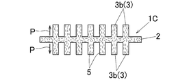
図6に示した本発明の第3実施形態に係るヒートシンク1Cでは、各フィン部3は、ピン状であり、すなわちピンフィン部3bである。そして、多数のピンフィン部3bは、ベースプレート部2に対してその厚さ方向の両側にそれぞれピン状に突出した状態にベースプレート部2に一体形成されている。また、ベースプレート部2の厚さ方向の一方の片側に突出したピンフィン部3bの位置と、ベースプレート部2の厚さ方向の他方の片側に突出したピンフィン部3bの位置とは、ベースプレート部2の幅方向(図6において左右方向)において一致している。
図7に示した本発明の第4実施形態に係るヒートシンク1Dでは、上記第3実施形態のヒートシンク1Cと同じく、各フィン部3は、ピン状であり、すなわちピンフィン部3bである。そして、多数のピンフィン部3bは、ベースプレート部に2対してその厚さ方向の両側にそれぞれピン状に突出した状態にベースプレート部2に一体形成されている。しかるに、ベースプレート部2の厚さ方向の一方の片側に突出したピンフィン部3bの位置と、ベースプレート部2の厚さ方向の他方の片側に突出したピンフィン部3bの位置とは、ベースプレート部2の幅方向(図7において左右方向)においてずれている。
第3及び第4実施形態のヒートシンク1C、1Dでは、それぞれ、炭素粒子5として、炭素繊維、カーボンナノチューブ、グラフェン、天然黒鉛粒子及び人造黒鉛粒子からなる群より選択される少なくとも一種が用いられる。
上述した第2~第4実施形態のヒートシンク1B~1Dは、いずれも、各ピンフィン部3b中に存在する炭素粒子5がベースプレート部に対するピンフィン部3bの突出方向Pに配向しているので、各ピンフィン部3bの突出方向Pの熱伝導率は高い。したがって、ヒートシンク1B~1Dは高い冷却性能を有している。
これらのヒートシンク1B~1Dは、冷却器の筐体本体内に配置されて使用されても良いし、冷却器の筐体本体内に配置されないで使用されても良い。
以上で本発明の幾つかの実施形態を説明したが、本発明はこれらの実施形態に限定されるものではなく、本発明の要旨を逸脱しない範囲で様々に変更可能である。
上記第1実施形態のヒートシンク1Aのように、複数のフィン部として複数のストレートフィン部を有するヒートシンクは、上記第1実施形態のように押出型材で形成することが特に望ましいが、本発明ではそのようなヒートシンクは、その他に例えば熱間鍛造加工(例:熱間型鍛造加工)により形成しても良い。
次に、本発明の具体的な実施例を以下に説明する。ただし本発明は以下の実施例に限定されるものではない。
<実施例1>
図1に示した第1実施形態のヒートシンク1Aを次のように製造した。
図1に示した第1実施形態のヒートシンク1Aを次のように製造した。
アルミニウムと炭素粒子5としての鱗片状黒鉛粉末との複合材からなるビレット45を準備した。複合材は、アルミニウム粉末と鱗片状黒鉛粉末とを混合して焼結することにより製造されたものである。
次いで、ビレット45を押出加工することにより、所望するヒートシンク1Aの断面形状と同じ断面形状を有する長尺な押出型材46を得た。そして、押出型材46を所定の長さに切断することにより、ヒートシンク1Aを得た。
得られたヒートシンク1Aの冷却性能は、アルミニウム製ヒートシンクのそれよりも優れていた。
<実施例2>
図4に示した第2実施形態のヒートシンク1Bを次のように製造した。
図4に示した第2実施形態のヒートシンク1Bを次のように製造した。
アルミニウムと炭素粒子5としての短炭素繊維との複合材からなる板状の鍛造素材35を準備した。複合材は、アルミニウム粉末と短炭素繊維とを混合して焼結することにより製造されたものである。
次いで、鍛造素材35を熱間型鍛造加工することにより、ヒートシンク1Bを得た。
得られたヒートシンク1Bの冷却性能は、アルミニウム製ヒートシンクのそれよりも優れていた。
本願は、2016年6月7日付で出願された日本国特許出願の特願2016-113206号の優先権主張を伴うものであり、その開示内容は、そのまま本願の一部を構成するものである。
ここに用いられた用語及び表現は、説明のために用いられたものであって限定的に解釈するために用いられたものではなく、ここに示され且つ述べられた特徴事項の如何なる均等物をも排除するものではなく、この発明のクレームされた範囲内における各種変形をも許容するものであると認識されなければならない。
本発明は、多くの異なった形態で具現化され得るものであるが、この開示は本発明の原理の実施例を提供するものと見なされるべきであって、それら実施例は、本発明をここに記載しかつ/または図示した好ましい実施形態に限定することを意図するものではないという了解のもとで、多くの図示実施形態がここに記載されている。
本発明の図示実施形態を幾つかここに記載したが、本発明は、ここに記載した各種の好ましい実施形態に限定されるものではなく、この開示に基づいていわゆる当業者によって認識され得る、均等な要素、修正、削除、組み合わせ(例えば、各種実施形態に跨る特徴の組み合わせ)、改良及び/又は変更を有するありとあらゆる実施形態をも包含するものである。クレームの限定事項はそのクレームで用いられた用語に基づいて広く解釈されるべきであり、本明細書あるいは本願のプロセキューション中に記載された実施例に限定されるべきではなく、そのような実施例は非排他的であると解釈されるべきである。例えば、この開示において、「preferably」という用語は非排他的なものであって、「好ましいがこれに限定されるものではない」ということを意味するものである。
本発明は、発熱性素子等の発熱体を冷却するためのヒートシンク及び冷却器並びにヒートシンクの製造方法に利用可能である。
1A~1D:ヒートシンク
2:ベースプレート部
3:フィン部
3a:ストレートフィン部
3b:ピンフィン部
5:炭素粒子
10:冷却器
20:絶縁基板
30:熱間鍛造用金型
35:鍛造素材
45:ビレット
46:押出型材
P:フィン部の突出方向
2:ベースプレート部
3:フィン部
3a:ストレートフィン部
3b:ピンフィン部
5:炭素粒子
10:冷却器
20:絶縁基板
30:熱間鍛造用金型
35:鍛造素材
45:ビレット
46:押出型材
P:フィン部の突出方向
Claims (5)
- アルミニウムと炭素粒子との複合材製であり、
ベースプレート部に複数のフィン部が前記ベースプレート部に対して突出した状態に一体形成されており、
前記フィン部中に存在する炭素粒子が前記ベースプレート部に対する前記フィン部の突出方向に配向しているヒートシンク。 - 前記炭素粒子として鱗片状黒鉛粒子が用いられている請求項1記載のヒートシンク。
- 請求項1又は2記載のヒートシンクを備えた冷却器。
- 請求項1又は2記載のヒートシンクを、アルミニウムと炭素粒子との複合材からなる鍛造素材を熱間鍛造加工することにより形成するヒートシンクの製造方法。
- 請求項2記載のヒートシンクを、アルミニウムと炭素粒子との複合材からなるビレットを押出加工することにより得られた押出型材で形成するヒートシンクの製造方法。
Priority Applications (3)
| Application Number | Priority Date | Filing Date | Title |
|---|---|---|---|
| DE112017002842.6T DE112017002842T5 (de) | 2016-06-07 | 2017-05-30 | Kühlkörper und Kühleinrichtung |
| US16/307,596 US20190311970A1 (en) | 2016-06-07 | 2017-05-30 | Heat sink and cooling device |
| CN201780031096.XA CN109155294A (zh) | 2016-06-07 | 2017-05-30 | 散热器和冷却器 |
Applications Claiming Priority (2)
| Application Number | Priority Date | Filing Date | Title |
|---|---|---|---|
| JP2016-113206 | 2016-06-07 | ||
| JP2016113206A JP6846879B2 (ja) | 2016-06-07 | 2016-06-07 | ヒートシンクの製造方法 |
Publications (1)
| Publication Number | Publication Date |
|---|---|
| WO2017212982A1 true WO2017212982A1 (ja) | 2017-12-14 |
Family
ID=60578707
Family Applications (1)
| Application Number | Title | Priority Date | Filing Date |
|---|---|---|---|
| PCT/JP2017/020101 Ceased WO2017212982A1 (ja) | 2016-06-07 | 2017-05-30 | ヒートシンク及び冷却器 |
Country Status (5)
| Country | Link |
|---|---|
| US (1) | US20190311970A1 (ja) |
| JP (1) | JP6846879B2 (ja) |
| CN (1) | CN109155294A (ja) |
| DE (1) | DE112017002842T5 (ja) |
| WO (1) | WO2017212982A1 (ja) |
Families Citing this family (16)
| Publication number | Priority date | Publication date | Assignee | Title |
|---|---|---|---|---|
| US10791651B2 (en) * | 2016-05-31 | 2020-09-29 | Carbice Corporation | Carbon nanotube-based thermal interface materials and methods of making and using thereof |
| TWI755492B (zh) | 2017-03-06 | 2022-02-21 | 美商卡爾拜斯有限公司 | 基於碳納米管的熱界面材料及其製造和使用方法 |
| JP7170457B2 (ja) * | 2017-12-27 | 2022-11-14 | 昭和電工株式会社 | 組電池装置 |
| JP7033470B2 (ja) * | 2018-03-08 | 2022-03-10 | 昭和電工株式会社 | ヒートシンクの製造方法 |
| JP7007972B2 (ja) * | 2018-03-29 | 2022-01-25 | 昭和電工株式会社 | 放熱フィン、放熱器及び放熱器の製造方法 |
| JP7049951B2 (ja) * | 2018-07-11 | 2022-04-07 | 昭和電工株式会社 | 積層材 |
| DE102018218831B4 (de) * | 2018-11-05 | 2021-09-30 | Robert Bosch Gmbh | Kühlkörper sowie Kühlanordnung mit Kühlkörper |
| DE102019102505B4 (de) * | 2019-01-31 | 2021-09-30 | R. Stahl Schaltgeräte GmbH | Explosionsgeschützte Vorrichtung mit zünddurchschlag-sicherem Gasströmungspfad und Kühlkörper |
| KR102219180B1 (ko) * | 2019-03-22 | 2021-02-23 | 부경대학교 산학협력단 | 알루미늄계 클래드 형재의 제조 방법 및 이를 이용하여 제조된 알루미늄계 클래드 형재 |
| KR102266847B1 (ko) * | 2019-04-15 | 2021-06-21 | 부경대학교 산학협력단 | 복합재료 제조를 위한 소성 가공용 빌렛의 제조방법 및 이에 의해 제조된 빌렛 |
| KR102228431B1 (ko) * | 2019-04-16 | 2021-03-16 | 부경대학교 산학협력단 | 알루미늄계 클래드 방열판의 제조방법 및 이에 의해 제조된 알루미늄계 클래드 방열판 |
| JP7404845B2 (ja) * | 2019-12-17 | 2023-12-26 | 株式会社レゾナック | ヒートシンク |
| DE102020205686A1 (de) | 2020-05-06 | 2021-11-11 | Robert Bosch Gesellschaft mit beschränkter Haftung | Elektronikvorrichtung |
| CN112366188B (zh) * | 2020-08-24 | 2023-07-25 | 杰群电子科技(东莞)有限公司 | 一种具有散热齿片的半导体器件封装结构及封装方法 |
| CN112695221A (zh) * | 2020-12-19 | 2021-04-23 | 无锡盛旭复合材料有限公司 | 一种多层石墨烯增强铝基复合材料的制备方法 |
| JP7603279B2 (ja) * | 2021-03-29 | 2024-12-20 | 株式会社アカネ | ヒートシンク部材 |
Citations (4)
| Publication number | Priority date | Publication date | Assignee | Title |
|---|---|---|---|---|
| JP2011241432A (ja) * | 2010-05-17 | 2011-12-01 | Nissei Plastics Ind Co | 高熱伝導性複合材料の製造方法 |
| JP2014141746A (ja) * | 2012-12-27 | 2014-08-07 | Shibaura Institute Of Technology | 放熱用複合材及びその製造方法並びに放熱用複合材製造用の混合粉 |
| JP2015053397A (ja) * | 2013-09-06 | 2015-03-19 | 住友精密工業株式会社 | 高熱伝導板 |
| JP2015144264A (ja) * | 2013-12-25 | 2015-08-06 | 三菱マテリアル株式会社 | パワーモジュール用基板、およびその製造方法、パワーモジュール |
Family Cites Families (5)
| Publication number | Priority date | Publication date | Assignee | Title |
|---|---|---|---|---|
| JP5917992B2 (ja) | 2012-04-19 | 2016-05-18 | 昭和電工株式会社 | 絶縁基板の製造方法 |
| JP5989465B2 (ja) | 2012-09-05 | 2016-09-07 | 昭和電工株式会社 | 絶縁基板の製造方法 |
| JP6118583B2 (ja) | 2013-02-20 | 2017-04-19 | 昭和電工株式会社 | 絶縁基板 |
| JP6050140B2 (ja) | 2013-02-20 | 2016-12-21 | 昭和電工株式会社 | 絶縁基板 |
| JP6430807B2 (ja) | 2014-12-18 | 2018-11-28 | 赤武エンジニアリング株式会社 | フレコンバッグ排出装置 |
-
2016
- 2016-06-07 JP JP2016113206A patent/JP6846879B2/ja active Active
-
2017
- 2017-05-30 CN CN201780031096.XA patent/CN109155294A/zh active Pending
- 2017-05-30 DE DE112017002842.6T patent/DE112017002842T5/de not_active Withdrawn
- 2017-05-30 WO PCT/JP2017/020101 patent/WO2017212982A1/ja not_active Ceased
- 2017-05-30 US US16/307,596 patent/US20190311970A1/en not_active Abandoned
Patent Citations (4)
| Publication number | Priority date | Publication date | Assignee | Title |
|---|---|---|---|---|
| JP2011241432A (ja) * | 2010-05-17 | 2011-12-01 | Nissei Plastics Ind Co | 高熱伝導性複合材料の製造方法 |
| JP2014141746A (ja) * | 2012-12-27 | 2014-08-07 | Shibaura Institute Of Technology | 放熱用複合材及びその製造方法並びに放熱用複合材製造用の混合粉 |
| JP2015053397A (ja) * | 2013-09-06 | 2015-03-19 | 住友精密工業株式会社 | 高熱伝導板 |
| JP2015144264A (ja) * | 2013-12-25 | 2015-08-06 | 三菱マテリアル株式会社 | パワーモジュール用基板、およびその製造方法、パワーモジュール |
Also Published As
| Publication number | Publication date |
|---|---|
| JP6846879B2 (ja) | 2021-03-24 |
| DE112017002842T5 (de) | 2019-02-28 |
| CN109155294A (zh) | 2019-01-04 |
| US20190311970A1 (en) | 2019-10-10 |
| JP2017220539A (ja) | 2017-12-14 |
Similar Documents
| Publication | Publication Date | Title |
|---|---|---|
| JP6846879B2 (ja) | ヒートシンクの製造方法 | |
| JP6064886B2 (ja) | 熱伝導性応力緩和構造体 | |
| US20100326645A1 (en) | Thermal pyrolytic graphite laminates with vias | |
| US20110226458A1 (en) | Modular heat sink and method for fabricating same | |
| EP3759735B1 (en) | Thermal gasket with high transverse thermal conductivity | |
| CN114071951A (zh) | 散热器及其制造方法 | |
| JP2016066639A (ja) | 接続方法が異なる複数のフィンを備えたヒートシンク | |
| JP7049849B2 (ja) | 冷却装置 | |
| JP2005077052A (ja) | 平面型ヒートパイプ | |
| JP7133020B2 (ja) | 高コンダクタンス熱リンク | |
| JP6544983B2 (ja) | 冷却基板 | |
| JP7201658B2 (ja) | 冷却装置 | |
| JP6698046B2 (ja) | 熱伝導シート | |
| JP6708498B2 (ja) | 冷却器及びその製造方法 | |
| KR101842522B1 (ko) | 열전도성의 나노헤어층과 이것을 이용한 방열구조체 | |
| JP7129316B2 (ja) | 沸騰伝熱部材および沸騰冷却装置 | |
| JP7404845B2 (ja) | ヒートシンク | |
| JP2014192401A (ja) | ヒートシンク | |
| CN221531984U (zh) | 全方位导热散热片 | |
| WO2019106874A1 (ja) | 絶縁基板及び放熱装置 | |
| JP7302446B2 (ja) | 放熱装置 | |
| JP6670605B2 (ja) | 絶縁基板の製造方法 | |
| JP2019041076A (ja) | 放熱装置用フィン及び放熱装置 | |
| CN121057160A (zh) | 用于将冷却体与功率模块传力锁合地连接起来的装置 | |
| JP2020038887A (ja) | 冷却装置 |
Legal Events
| Date | Code | Title | Description |
|---|---|---|---|
| 121 | Ep: the epo has been informed by wipo that ep was designated in this application |
Ref document number: 17810161 Country of ref document: EP Kind code of ref document: A1 |
|
| 122 | Ep: pct application non-entry in european phase |
Ref document number: 17810161 Country of ref document: EP Kind code of ref document: A1 |