WO2017212947A1 - 無線通信装置及び機器 - Google Patents
無線通信装置及び機器 Download PDFInfo
- Publication number
- WO2017212947A1 WO2017212947A1 PCT/JP2017/019677 JP2017019677W WO2017212947A1 WO 2017212947 A1 WO2017212947 A1 WO 2017212947A1 JP 2017019677 W JP2017019677 W JP 2017019677W WO 2017212947 A1 WO2017212947 A1 WO 2017212947A1
- Authority
- WO
- WIPO (PCT)
- Prior art keywords
- signal
- receiving element
- light
- wireless communication
- light receiving
- Prior art date
- Legal status (The legal status is an assumption and is not a legal conclusion. Google has not performed a legal analysis and makes no representation as to the accuracy of the status listed.)
- Ceased
Links
Images










Classifications
-
- B—PERFORMING OPERATIONS; TRANSPORTING
- B25—HAND TOOLS; PORTABLE POWER-DRIVEN TOOLS; MANIPULATORS
- B25J—MANIPULATORS; CHAMBERS PROVIDED WITH MANIPULATION DEVICES
- B25J19/00—Accessories fitted to manipulators, e.g. for monitoring, for viewing; Safety devices combined with or specially adapted for use in connection with manipulators
- B25J19/0025—Means for supplying energy to the end effector
- B25J19/0029—Means for supplying energy to the end effector arranged within the different robot elements
-
- H—ELECTRICITY
- H04—ELECTRIC COMMUNICATION TECHNIQUE
- H04B—TRANSMISSION
- H04B10/00—Transmission systems employing electromagnetic waves other than radio-waves, e.g. infrared, visible or ultraviolet light, or employing corpuscular radiation, e.g. quantum communication
- H04B10/50—Transmitters
- H04B10/501—Structural aspects
- H04B10/502—LED transmitters
-
- B—PERFORMING OPERATIONS; TRANSPORTING
- B25—HAND TOOLS; PORTABLE POWER-DRIVEN TOOLS; MANIPULATORS
- B25J—MANIPULATORS; CHAMBERS PROVIDED WITH MANIPULATION DEVICES
- B25J9/00—Program-controlled manipulators
- B25J9/02—Program-controlled manipulators characterised by movement of the arms, e.g. cartesian coordinate type
- B25J9/04—Program-controlled manipulators characterised by movement of the arms, e.g. cartesian coordinate type by rotating at least one arm, excluding the head movement itself, e.g. cylindrical coordinate type or polar coordinate type
- B25J9/041—Cylindrical coordinate type
- B25J9/042—Cylindrical coordinate type comprising an articulated arm
-
- H—ELECTRICITY
- H04—ELECTRIC COMMUNICATION TECHNIQUE
- H04B—TRANSMISSION
- H04B10/00—Transmission systems employing electromagnetic waves other than radio-waves, e.g. infrared, visible or ultraviolet light, or employing corpuscular radiation, e.g. quantum communication
- H04B10/11—Arrangements specific to free-space transmission, i.e. transmission through air or vacuum
- H04B10/114—Indoor or close-range type systems
-
- H—ELECTRICITY
- H04—ELECTRIC COMMUNICATION TECHNIQUE
- H04B—TRANSMISSION
- H04B10/00—Transmission systems employing electromagnetic waves other than radio-waves, e.g. infrared, visible or ultraviolet light, or employing corpuscular radiation, e.g. quantum communication
- H04B10/11—Arrangements specific to free-space transmission, i.e. transmission through air or vacuum
- H04B10/114—Indoor or close-range type systems
- H04B10/1141—One-way transmission
-
- H—ELECTRICITY
- H04—ELECTRIC COMMUNICATION TECHNIQUE
- H04B—TRANSMISSION
- H04B10/00—Transmission systems employing electromagnetic waves other than radio-waves, e.g. infrared, visible or ultraviolet light, or employing corpuscular radiation, e.g. quantum communication
- H04B10/60—Receivers
- H04B10/66—Non-coherent receivers, e.g. using direct detection
- H04B10/67—Optical arrangements in the receiver
- H04B10/671—Optical arrangements in the receiver for controlling the input optical signal
-
- H—ELECTRICITY
- H04—ELECTRIC COMMUNICATION TECHNIQUE
- H04L—TRANSMISSION OF DIGITAL INFORMATION, e.g. TELEGRAPHIC COMMUNICATION
- H04L5/00—Arrangements affording multiple use of the transmission path
- H04L5/003—Arrangements for allocating sub-channels of the transmission path
- H04L5/0048—Allocation of pilot signals, i.e. of signals known to the receiver
Definitions
- the present invention relates to a wireless communication device that performs non-contact communication and a device including the wireless communication device.
- Non-contact communication methods include an electric field coupling method through capacitance, a magnetic field coupling method through electromagnetic induction, and an optical coupling method in which light is transmitted between a light emitting element and a light receiving element.
- Patent Document 1 describes an optical coupling method in which a light emitting element is disposed on a rotating body and a light emitting element is disposed on a stationary body.
- the intensity of light received by the light receiving element changes according to the rotation angle of the rotating body on which the light emitting element is arranged. That is, when the light emitting element and the light receiving element face each other, the intensity of light received by the light receiving element is maximum, but the rotating body rotates 180 degrees from the state where the light emitting element faces the light receiving element. Then, the intensity of light received by the light receiving element is minimized.
- the optical signal is converted into an electric signal and the logic of the data is determined. For example, if the electrical signal is above the logic determination level, it is determined as logic 1 data, and if it is below, it is determined as logic 0 data.
- Patent Document 1 describes a configuration of one-way communication.
- it is further necessary to dispose a light emitting element on a stationary body and a light receiving element on a rotating body. Therefore, in the case of performing non-contact bidirectional communication, it is necessary to prevent an error from occurring in data determined on the receiving side in communication in any direction of bidirectional communication.
- Such a problem does not occur only in the wireless communication using light described in Patent Document 1, but may occur in any wireless communication such as wireless communication using radio waves and wireless communication using electric and magnetic fields.
- the present invention has an object to prevent an error in data determined on the receiving side due to the attenuation of the radio signal at any receiving side when performing contactless communication with a simple configuration. To do.
- the wireless communication apparatus of the present invention includes a first transmission unit provided in a first member, and a first reception unit provided in a second member, the relative distance of which varies from the first transmission unit.
- the first transmission unit generates a first electrical signal obtained by superimposing a pilot signal on a first digital signal to be transmitted, and the first electrical signal
- a first wireless signal having a strength corresponding to the first wireless signal
- the first receiving unit generates a second electrical signal corresponding to the strength of the received first wireless signal to generate the second electrical signal.
- a pilot signal component is detected from the signal, and the second electric signal is amplified according to the attenuation amount of the pilot signal component.
- the present invention when two-way communication is performed in a non-contact manner, it is possible to prevent an error in data determined on the receiving side due to attenuation of the radio signal on any receiving side with a simple configuration. it can.
- FIG. 1 is a block diagram showing a bidirectional communication apparatus according to a first embodiment. It is a perspective view which shows the peripheral part of the drive device arrange
- FIG. 1 is a perspective view showing a robot apparatus as an example of a device according to the first embodiment.
- the robot apparatus 100 is a device includes a robot 200, a electronic controller 300 0 a robot controller for controlling a robot 200, a.
- the robot 200 is fixed to the gantry 150.
- the robot 200 includes a vertically articulated robot arm 201 and a robot hand 202 as an end effector that is a hand of the robot 200 and is attached to the tip of the robot arm 201.
- the robot arm 201 has a plurality of links 210 to 216 connected to be swingable or rotatable at joints J1 to J6.
- the robot arm 201 is composed of six-axis joints J1 to J6, which are four axes that swing and two axes that rotate.
- the swinging joint is called a swinging joint
- the rotating joint is called a rotating joint.
- joints J1 and J6 are rotary joints
- joints J2, J3, J4, and J5 are swing joints.
- the link 211 can rotate 360 degrees or more in the forward / reverse direction relative to the link 210
- the joint J6, the link 216 in the forward / reverse direction relative to the link 215 is 360 degrees.
- the above rotation is possible.
- the robot hand 202 is detachable at a joint J6 at the tip of the robot arm 201.
- Each joint J1 to J6 of the robot arm 201 is provided with a drive device (not shown) that drives the joint and electronic control devices 300 1 to 300 6 that control the drive device.
- a drive device (not shown) includes a motor and a speed reducer.
- These electronic control devices 300 0 to 300 6 are communicably connected to each other via a bus wiring 310 to constitute a bus communication system 320.
- the bus wiring 310 is provided inside or outside the robot arm 201.
- the electronic control unit 300 0 outputs a data signal (digital signal) of a position command value indicating the target rotational position of the motor to each of the electronic control units 300 1 to 300 6 via the bus wiring 310.
- Each of the electronic control devices 300 1 to 300 6 acquires a detection value of a rotary encoder attached to the motor, and controls the rotation of the motor so that the detection value approaches the input position command value.
- Each of the electronic control devices 300 1 to 300 6 outputs a detection value data signal (digital signal) to the electronic control device 300 0 via the bus wiring 310.
- the bus communication system 320 employs CAN (Control Area Network) in order to communicate large amounts of data at high speed.
- the nodes connected to the bus wiring 310 are the electronic control devices 300 0 to 300 6 .
- the electronic control devices 300 0 to 300 6 communicate data signals on the bus wiring 310 using differential signals.
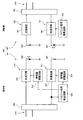
- FIG. 2 is an explanatory diagram showing the bus communication system 320 according to the first embodiment.
- the bus wiring 310 is physically separated into a plurality of bus wirings 310 1 , 310 2 , and 310 3 so that the link can freely rotate at the joints J1 and J6.
- a wireless communication apparatus that performs short-range two-way communication in a wireless (contactless) Two-way communication devices 400 are respectively arranged.
- Each bidirectional communication device 400 includes a pair of signal transmission devices 401 and 402 that perform wireless communication with each other.
- Each bidirectional communication device 400 is disposed at joints J1 and J6.
- the electronic control device 300 0 and the electronic control devices 300 1 , 300 2 , 300 3 , 300 4 , 300 5 , 300 6 perform data communication via the bidirectional communication device 400 disposed at each joint J1, J6. I do.
- termination resistors 315 are provided at both ends of each of the bus wirings 310 1 to 310 3 , respectively. As a result, signal reflection is prevented at both ends of each of the bus wirings 310 1 to 310 3 , and the voltage of the bus wiring is optimized.
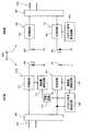
- FIG. 3 is a block diagram showing the bidirectional communication apparatus according to the first embodiment.
- the bidirectional communication devices 400 arranged at the joint J1 and the joint J6 have the same configuration, the bidirectional communication device 400 arranged at one joint J1 will be described.
- the bidirectional communication apparatus 400 is arrange
- the bidirectional communication device 400 may be arranged at one of the joint J1 and the joint J6, and the other may use a toggle wiring or a slip ring.
- the bidirectional communication device 400 includes a signal transmission device 401 provided on the link 210 that is the fixed side, and a signal transmission device 402 provided on the link 211 that is the rotation side.
- Signal transmission device 401 includes a signal control unit 405 connected to bus lines 310 1, a transmitter 412 and a receiver 421 connected to the signal control unit 405, a light emitting element 432 connected to the transmitting unit 412, receiving A light receiving element 441 connected to the portion 421.
- Signal transmission device 402 includes a signal control unit 406 connected to the bus line 310 2, a transmitter 411 and a receiver 422 connected to the signal control unit 406, a light emitting element 431 connected to the transmitting unit 411, receiving A light receiving element 442 connected to the portion 422.
- the signal control devices 405 and 406 include a CAN repeater circuit for connecting the two bus wirings 310 1 and 310 2 to one or both of them.
- the light emitting element 431 is a first transmitting element
- the light receiving element 441 is a first receiving element
- the light emitting element 432 is a second transmitting element
- the light receiving element 442 is a second receiving element.
- the transmission unit 411 is a first transmission unit
- the reception unit 421 is a first reception unit
- the transmission unit 412 is a second transmission unit
- the reception unit 422 is a second reception unit.
- the light emitting elements 431 and 432 are LEDs, more specifically infrared light emitting diodes. Note that the light emitting elements 431 and 432 are not limited to this, and may be a visible light emitting diode, a laser diode, or the like. In the first embodiment, the light emitting element 431 and the light emitting element 432 emit light having the same wavelength, and are of the same standard.
- the light receiving elements 441 and 442 are photodiodes, specifically, SiPIN photodiodes. The light receiving elements 441 and 442 are not limited to this, and may be visible light photodiodes or the like. The light receiving elements 441 and 442 may be phototransistors.
- the size of the light emitting elements 431 and 432 may be about 3 [mm] ⁇ 1.5 [mm].
- the size of the light receiving elements 441 and 442 may be about 5.5 [mm] ⁇ 4.8 [mm]. In this case, one side of the light receiving surfaces of the light receiving elements 441 and 442 is about 5 mm.
- Signal control unit 405 when receiving the input of the differential signal is a data signal from the electronic control unit 300 0 via the bus line 310 1, and outputs to the transmitting unit 412 converts the differential signal into a single-ended signal .
- the transmission unit 412 supplies an electric signal for driving the light emitting element 432 to the light emitting element 432 according to the single end signal received from the signal control device 405.
- the light emitting element 432 emits light with a light emission intensity corresponding to the intensity (voltage) of the electric signal supplied from the transmission unit 412. Thereby, the light emitting element 432 transmits an optical signal as a wireless signal.
- the light receiving element 442 receives (receives) an optical signal as a wireless signal.
- the receiving unit 422 generates an electrical signal corresponding to the intensity of the optical signal received by the light receiving element 442, and outputs the generated electrical signal (single end signal) to the signal control device 406.
- Signal control unit 406 performs a logical determination of the electrical signal received the input from the reception unit 422, and generates a differential signal in accordance with the determination result, and outputs to the bus line 310 2.
- the signal controller 406 when receiving the input of the differential signal is a data signal from the electronic control unit 300 1 to 300 6 via the bus line 310 2, converts the differential signal into a single-ended signal transmission Output to the unit 411.
- the transmission unit 411 supplies an electric signal for driving the light emitting element 431 to the light emitting element 431 in accordance with the single end signal received from the signal control device 406.
- the light emitting element 431 emits light with a light emission intensity corresponding to the intensity (voltage) of the electric signal supplied from the transmission unit 411. Thereby, the light emitting element 431 transmits an optical signal as a radio signal.
- the light receiving element 441 receives (receives) an optical signal as a wireless signal.
- the receiving unit 421 generates an electrical signal corresponding to the intensity of the optical signal received by the light receiving element 441, and outputs the generated electrical signal (single end signal) to the signal control device 405.
- Signal control unit 405 performs a logical determination of the electrical signal received the input from the reception unit 421, and generates a differential signal in accordance with the determination result, and outputs to the bus lines 310 1.
- FIG. 4 is a perspective view showing a driving device arranged at a joint J1 which is a rotary joint of the robot arm according to the first embodiment and a peripheral portion of the driving device.
- the joint J6 which is a rotating joint, has the same configuration and will not be described.
- the drive device 250 disposed at the joint J1 is configured to rotationally drive the other link 211 with respect to one link 210 of the pair of links 210 and 211, and includes a motor (and a speed reducer). Has been.
- the stator of the driving device 250 is fixed to one of the link 210 and the link 211, for example, the link 210 (FIG. 1).
- a cylindrical member 451 as a first member is fixedly attached to the link 210 to which the stator of the driving device 250 is fixed.
- a shaft member 452 that is a second member is fixedly attached to the rotary shaft 251 that extends from the rotor of the driving device 250.
- the shaft member 452 is disposed on the inner side of the cylindrical member 451 so as to be coaxial with the cylindrical member 451, and rotates relative to the cylindrical member 451 around the central axis C1 of the cylindrical member 451.
- the shaft member 452 is fixed to the other of the link 210 and the link 211, for example, the link 211. Thereby, the driving force of the driving device 250 is transmitted to the link 211, and the link 211 rotates with respect to the link 210.
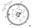
- FIG. 5 is an explanatory diagram showing an arrangement relationship between the light emitting element and the light receiving element.
- FIG. 5 is a view of the structure shown in FIG. 4 as viewed from the Z direction.
- the light emitting element 431 and the light receiving element 442 of the signal transmission device 402 are arranged on the shaft member 452 in the first embodiment, one of the cylindrical member 451 and the shaft member 452.
- the light emitting element 432 and the light receiving element 441 of the signal transmission device 401 are arranged on the other of the cylindrical member 451 and the shaft member 452, in the first embodiment, on the cylindrical member 451. More specifically, the light emitting element 431 and the light receiving element 442 are fixed to the outer peripheral surface of the shaft member 452, and the light emitting element 432 and the light receiving element 441 are fixed to the inner peripheral surface of the cylindrical member 451. Therefore, the light emitting element 431 and the light receiving element 442 rotate in the circumferential direction R0 around the central axis C1 together with the shaft member 452.
- the circumferential direction R0 has two directions, a clockwise direction R1 and a counterclockwise direction R2 in FIG. 5, and the shaft member 452 is counterclockwise to the clockwise direction R1 by the driving device 250 (FIG. 4). It is selectively driven to rotate in any one of the two directions of the clockwise direction R2.
- the transmission partner of the light emitting element 431 disposed on the shaft member 452 is the light receiving element 441 disposed on the cylindrical member 451.
- the transmission partner of the light emitting element 432 disposed on the cylindrical member 451 is the light receiving element 442 disposed on the shaft member 452. Thereby, non-contact communication is performed.
- the shaft member 452 is a hollow cylindrical member using a white resin having a diameter of 20 [mm], a length of 14 [mm], and a thickness of 2 [mm], for example.
- the cylindrical member 451 is a hollow cylindrical member using a white resin having a diameter of 64 [mm], a length of 14 [mm], and a thickness of 2 [mm], for example.
- the inner peripheral surface of the cylindrical member 451 and the outer peripheral surface of the shaft member 452 are reflection surfaces that reflect light. Wirings connected to the light emitting element 431 and the light receiving element 442 are arranged inside the shaft member 452.
- white resin lid members 453 and 454 are arranged at both ends of the cylindrical member 451 in the Z direction.
- the lid members 453 and 454 have a role of confining light and reducing light attenuation due to diffusion, and the dynamic range of amplification correction described later can be narrowed compared to the case without the lid members 453 and 454.
- a hole having a diameter of 20 [mm] is formed at the center where the shaft member 452 is disposed.
- the hole of the lid member 453 is through which the rotating shaft 251 of the driving device 250 passes.
- the hole of the lid member 454 is used for drawing out the wiring connected to the light emitting element 431 and the light receiving element 442.
- the wiring may be drawn through the surface of the shaft member 452 without making the shaft member 452 hollow.
- a gap is required between the shaft member 452 and the cylindrical member 451 by the amount of wiring, and light is leaked from the gap. Attenuation occurs. Leakage from the gap can be reduced by making the shaft member 452 hollow.
- the light emitting element 431, the light emitting element 432, the light receiving element 441, and the light receiving element 442 are disposed in the same space serving as a wireless transmission path, thereby saving space.
- the robot arm 201 can be reduced in size and weight can be reduced, so that the controllability of the robot arm 201 is improved.
- the light emitting element 431, the light emitting element 432, the light receiving element 441, and the light receiving element 442 are at the same position in the Z direction in which the central axis C1 that is the rotation axis of the rotating shaft 251 extends, that is, Z that the central axis C1 extends. They are arranged in the same plane in the direction.
- the light emitting element 431 and the light receiving element 442 are arranged at different positions in the circumferential direction R0 so that the light emitting element 431 and the light receiving element 442 do not overlap.
- the light emitting element 432 and the light receiving element 441 are arranged at different positions in the circumferential direction R0 so that the light emitting element 432 and the light receiving element 441 do not overlap.
- an angle (first angle) formed by a straight line L1 extending from the central axis C1 to the center of the light emitting element 431 and a straight line L2 extending from the central axis C1 to the center of the light receiving element 442 is an angle.
- ⁇ 1 an angle formed by a straight line L3 extending from the central axis C1 to the center of the light emitting element 432 and a straight line L4 extending from the central axis C1 to the center of the light receiving element 441 is an angle ⁇ 2.
- the light emitting elements 431 and 432 and the light receiving elements 441 and 442 are disposed at positions where the angle ⁇ 1 and the angle ⁇ 2 are equal when viewed from the Z direction.
- the angles ⁇ 1 and ⁇ 2 are 180 degrees.
- the positional relationship between the light emitting element 431 and the light receiving element 442 fixed to the shaft member 452 and the positional relationship between the light emitting element 432 and the light receiving element 441 fixed to the cylindrical member 451 are symmetrical at 180 degrees. ing.
- FIG. 6A is an explanatory diagram showing a state in which the rotation angle of the shaft member with respect to the reference is 0 degree with reference to the state where the light emitting element and the light receiving element face each other, and FIG. It is explanatory drawing which shows the state of a degree.
- the light emitting element 431 and the light receiving element 441, and the light emitting element 432 and the light receiving element 442 face each other. Therefore, the light-emitting element 431 and the light receiving element 441, and the light-emitting element 432 and light receiving element 442 closest, the optical path P U, is the shortest P D, the uplink communication, the smallest attenuation of light both downlink communications, The received light intensity received by the light receiving elements 441 and 442 is the highest.
- FIG. 7 is a graph showing the relative value of the light receiving intensity of each of the light receiving elements 441 and 442 with respect to the rotation angle of the shaft member 452 in the first embodiment.
- the light reception intensity of the light receiving element 442 (uplink communication) is indicated by a solid line
- the light reception intensity of the light reception element 441 (downlink communication) is indicated by a broken line.
- the positional relationship between the light emitting element 431 and the light receiving element 442 on the shaft member 452 side is symmetrical to the positional relationship between the light emitting element 432 and the light receiving element 441 on the cylindrical member 451 side. That is, the angle ⁇ 1 and the angle ⁇ 2 are equal to 180 degrees. For this reason, as shown in FIG. 7, the change in the light receiving intensity of the light receiving element 441 with respect to the rotation angle of the shaft member 452 is equal to the change in the light receiving intensity of the light receiving element 442 with respect to the rotation angle of the shaft member 452.
- the intensity of light transmitted from the light emitting element 431 to the light receiving element 442 becomes the lowest, and the intensity of light transmitted from the light emitting element 432 to the light receiving element 441 becomes the lowest.
- the light receiving sensitivity of the light receiving element 442 has a correlation with the ratio of the intensity of receiving light emitted from the light emitting element 431 that becomes interference light to the intensity of receiving light emitted from the light emitting element 432.
- the light receiving sensitivity of the light receiving element 441 has a correlation with the ratio of the intensity of receiving light emitted from the light emitting element 432 serving as interference light to the intensity of receiving light emitted from the light emitting element 431. Therefore, by setting the angles ⁇ 1 and ⁇ 2 to 180 degrees, the light receiving sensitivity of the light receiving elements 441 and 442 becomes the highest.
- FIG. 8 is a graph showing a measurement result of the light receiving intensity of the light receiving element 442 with respect to the rotation angle of the shaft member 452 when the light emitting intensity of the light emitting element 432 is constant.
- the horizontal axis represents the rotation angle of the shaft member 452
- the vertical axis represents the relative light reception intensity of the light receiving element 442.
- the light receiving intensity is reduced by 20 [dB] at 180 ° which is the farthest, compared with 0 ° at which the light emitting element 431 and the light receiving element 441 face each other closest to each other. Since the angles ⁇ 1 and ⁇ 2 are both 180 degrees, the light receiving element 442 has the same light receiving intensity as that of the light receiving element 441.
- the transmission unit 411 includes a transmission circuit 501 and a pilot signal superimposing circuit 502.
- the transmission unit 412 includes a transmission circuit 511 and an amplification amount adjustment circuit 512.
- the reception unit 421 includes a reception circuit 521, a pilot signal detection circuit 522, and an amplification amount adjustment circuit 523.
- the receiving unit 422 includes a receiving circuit 531.
- the transmission circuit 501 receives an input of an electrical signal that is a low-level or high-level first digital signal (single-end signal) to be transmitted from the signal control device 406.
- the pilot signal superimposing circuit 502 generates a pilot signal (for example, a sine wave having a predetermined frequency) having a frequency band different from that of the received electric signal.
- the pilot signal has a constant amplitude.
- the transmission circuit 501 generates an electrical signal in which a pilot signal is superimposed on a digital signal.
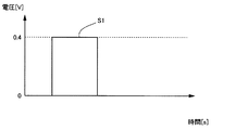
- FIG. 9A is a waveform diagram showing a digital signal received by the transmission circuit 501 from the signal control device 406.
- FIG. 9B is a waveform diagram showing a pilot signal generated by pilot signal superimposing circuit 502.
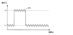
- FIG. 9C is a waveform diagram showing an electrical signal generated by superimposing a pilot signal on a digital signal.
- the signal input to the transmission circuit 501 is a digital signal S1 that is a first digital signal, and the high level voltage is 0.4 [V], for example, and the low level voltage is 0, for example. is there.
- the pilot signal superimposing circuit 502 generates a pilot signal SP having a voltage amplitude lower than the high level voltage of the digital signal S1, for example, 0.05 [V].
- the transmission circuit 501 generates an electric signal ST1 in which the pilot signal SP is superimposed on the digital signal S1, and outputs (applies) to the light emitting element 431.
- the biased electric signal ST1 is output (applied) to the light emitting element 431 in order to cause the light emitting element 431 to emit light even when the digital signal S1 is in a low level state.
- 1.1 [V] bias is applied.
- the intermediate voltage between the high level and the low level is 1.3 [V].
- the transmission circuit 501 biases the digital signal S1, the signal control device 406 may perform it.
- the light emitting element 431 transmits an optical signal (radio signal) having an intensity corresponding to the electric signal ST1 generated by the transmission unit 411 to the light receiving element 441. That is, the light emitting element 431 emits light with an intensity corresponding to the intensity (voltage) of the electric signal ST1 generated by the transmission unit 411.
- the light emitted from the light emitting element 431 propagates through the space between the shaft member 452 and the cylindrical member 451 and reaches the light receiving element 441.
- the light receiving element 441 receives (receives) an optical signal (wireless signal) transmitted from the light emitting element.
- the receiving circuit 521 generates an electrical signal corresponding to the intensity of light (radio signal) received (received) by the light receiving element 441.
- This electric signal includes a digital signal component and a pilot signal component.
- the pilot signal component attenuates according to the rotation angle of the shaft member 452, similarly to the digital signal component.
- the pilot signal detection circuit 522 is configured by a filter circuit, detects a pilot signal component from the electrical signal output from the reception circuit 521, and outputs the intensity of the pilot signal component as a detection result to the amplification amount adjustment circuit 523.
- the strength of an electric signal (including a pilot signal component) is a voltage.
- the amplification amount adjustment circuit 523 compares the strength of the pilot signal component with a predetermined reference strength (reference voltage), and the reception circuit 521 receives the input according to the attenuation amount of the strength of the pilot signal component with respect to the reference strength. Amplifies the strength of the electrical signal. Specifically, the amplification amount adjustment circuit 523 amplifies the intensity of the electric signal with a larger amplification amount as the attenuation amount is larger so as to cancel the attenuation amount. In this way, the reception intensity of the electrical signal obtained by the reception circuit 521 is amplified by the amount of attenuation of the pilot signal component.
- an electric signal with a stable high level and low level is output from the receiving circuit 521 of the receiving unit 421.
- the amplified electrical signal is output to the signal control device 405, and the signal control device 405 performs logic determination. Thereby, it is possible to prevent an error from occurring in the data (logic 0, 1) determined by the signal control device 405.
- a pilot signal component may be superimposed on the electrical signal output from the receiving unit 421 as long as there is no problem in the logic determination of the signal control device 405. Therefore, in the first embodiment, it is not necessary to arrange a separation circuit that separates the pilot signal component in the subsequent stage of the reception circuit 521.
- the transmission circuit 511 receives an input of an electrical signal that is a low-level or high-level second digital signal (single-end signal) to be transmitted from the signal control device 405.
- the pilot signal detection circuit 522 outputs the intensity of the pilot signal component to the amplification amount adjustment circuit 512 of the transmission unit 412.
- the amplification amount adjustment circuit 512 compares the strength of the pilot signal component with a predetermined reference strength, and amplifies the strength of the digital signal input by the transmission circuit 511 according to the attenuation amount of the strength of the pilot signal component with respect to the reference strength. .
- the amplification amount adjustment circuit 512 amplifies the intensity of the electric signal with a larger amplification amount as the attenuation amount is larger so as to cancel the attenuation amount.
- the light transmitted from the light emitting element 432 and received by the light receiving element 442 is attenuated similarly to the light transmitted from the light emitting element 431 and received by the light receiving element 441.
- the attenuation amount of the optical signal in downlink communication is equal to the attenuation amount of the optical signal in uplink communication. Therefore, in the first embodiment, the electrical signal is amplified by the transmission unit 412 in the upstream communication, just like the electrical signal is amplified by the reception unit 421 in the downstream communication. The electrical signal thus generated by amplification is output (applied) to the light emitting element 432.
- the light emitting element 432 transmits an optical signal (radio signal) having an intensity corresponding to the electrical signal generated by the transmission unit 412 to the light receiving element 442. That is, the light emitting element 432 emits light with an intensity corresponding to the intensity (voltage) of the electric signal generated by the transmission unit 412.
- the light emitted from the light emitting element 432 propagates through the space between the shaft member 452 and the cylindrical member 451 and reaches the light receiving element 442.
- the light receiving element 442 receives (receives) an optical signal (wireless signal) transmitted from the light emitting element.
- the receiving circuit 531 generates an electric signal corresponding to the intensity of light (radio signal) received (received) by the light receiving element 442.
- the optical signal received by the light receiving element 442 is attenuated when propagating through the space, but is attenuated by the transmitting unit 412, so that the attenuation is offset. Therefore, an optical signal having a stable intensity is received by the light receiving element 442 without being affected by light attenuation caused by the rotation of the shaft member 452. Thereby, even if the attenuation amount of the light intensity changes according to the rotation angle of the shaft member 452, an electric signal whose high level and low level are stable is output from the reception circuit 531 of the reception unit 422 to the signal control device 406. The Thereby, it is possible to prevent an error from occurring in the data (logic 0, 1) discriminated by the signal control device 406.
- the transmission unit 412 can omit the pilot signal superimposing circuit, and the receiving unit 422 can omit the pilot signal detection circuit.
- pilot signals are transmitted / received in downlink communication.
- the present invention is not limited to this, and pilot signals may be transmitted / received in uplink communication.
- the pilot signal superimposing circuit and the pilot signal detecting circuit can be omitted in the transmission unit 411 and the reception unit 421 that perform downlink communication.
- a pilot signal detection circuit and two amplification amount adjustment circuits are required on the rotation side, which increases the circuit mounting area and circuit power consumption on the rotation side.
- the rotation side such as the rotary joint of the robot arm 201, is limited in size and power, it is more effective to transmit and receive pilot signals in downlink communication.
- the light receiving element on the fixed side when the light receiving intensity when the light emitting element on the fixed side transmits low exceeds the light receiving intensity when the light emitting element on the rotating side transmits high, In some cases, it may be difficult to determine low / high in the light receiving element.
- the fixed-side light-emitting element and the fixed-side light-receiving element at a position of 180 degrees, the light from the fixed-side light-emitting element can be easily received by the fixed-side light-receiving element.
- the light receiving element on the side hardly receives light from the light emitting element on the rotation side.
- a pilot signal is superimposed on the light emitting element 431 on the rotating side, and when the light emitting element 432 on the fixed side is low, the light emitting element 432 on the fixed side is not illuminated. do it. From the above, the configuration of the first embodiment is effective.
- the positional relationship between the light emitting element and the light receiving element is expressed by the angles ⁇ 1 and ⁇ 2, and the respective angles ⁇ 1 and ⁇ 2 are set to 180 degrees.
- the change in received light intensity is 0 to There may be an error with respect to 180 degrees within a range of ⁇ 6 [dB].
- the angles ⁇ 1 and ⁇ 2 have an attenuation of ⁇ It may be in the range of 173 degrees to 187 degrees that is less than 6 [dB]. If the shift amount between the angles ⁇ 1 and ⁇ 2 is known, the amplification amount may be adjusted accordingly.
- FIG. 10A is an explanatory diagram showing an arrangement relationship between the light emitting elements and the light receiving elements in the second embodiment. Note that in the second embodiment, description of the same configuration as in the first embodiment will be omitted. In the two-way communication apparatus of the second embodiment, the arrangement relationship between the light emitting element 431 and the light receiving element 442 and the arrangement relationship between the light emitting element 432 and the light receiving element 442 are different from those in the first embodiment.
- the angles ⁇ 1 and ⁇ 2 are both 180 degrees
- the angles ⁇ 1 and ⁇ 2 are both 90 degrees.
- light is received from the light emitting element 432 in the direction R2 from the light emitting element 431 toward the light receiving element 442 in two directions in the rotational direction of the rotary shaft 251, that is, in two directions R1 and R2 in the circumferential direction R0.
- the direction R1 toward the element 441 is opposite.
- FIG. 10B is an explanatory diagram illustrating a state where the light emitting element and the light receiving element face each other. Similar to the first embodiment, when the light emitting element 431 and the light receiving element 441 face each other, the light emitting element 432 and the light receiving element 442 also face each other. Therefore, the light emitting element 431 and the light receiving element 441, the light emitting element 432 and the light receiving element 442 are closest to each other, and the optical paths P U and P D are the shortest. Therefore, as in the first embodiment, the amount of attenuation of light is the smallest in both uplink communication and downlink communication, and the received light intensity received by the light receiving elements 441 and 442 is the highest.
- the light emitting element 431 and the light receiving element 441, and the light emitting element 432 and the light receiving element 442 are directed to the opposite sides. Therefore, similarly to the first embodiment, the amount of attenuation of light is the largest in both uplink communication and downlink communication, and the received light intensity received by the light receiving elements 441 and 442 is the lowest.
- each transmission part 411,412 and each receiving part 421,422 are the structures similar to 1st Embodiment (refer FIG. 3).
- the receiving unit 421 only needs to amplify the intensity of the received electrical signal with a larger amplification amount as the attenuation amount of the pilot signal component is larger, and the transmission unit 412 has a larger amplification amount as the attenuation amount of the pilot signal component is larger. It is sufficient to amplify the intensity of the electrical signal transmitted by the.
- two-way communication can be stably performed regardless of the rotation angle of the shaft member 452 as in the first embodiment.
- angles ⁇ 1 and ⁇ 2 are not limited to 90 degrees, and even if the angles are larger than 0 degrees and smaller than 180 degrees, the same effects can be obtained as long as they are the same angle.
- FIG. 11 is an explanatory diagram showing an arrangement relationship between the light emitting elements and the light receiving elements in the third embodiment. Note that in the third embodiment, a description of the same configurations as those in the first and second embodiments is omitted.
- the arrangement relationship between the light emitting element 431 and the light receiving element 442 and the arrangement relationship between the light emitting element 432 and the light receiving element 442 are different from those in the first and second embodiments. Further, in the third embodiment, the function of the second transmission unit is different from those in the first and second embodiments.
- the angles ⁇ 1 and ⁇ 2 are both 180 degrees
- the angles ⁇ 1 and ⁇ 2 are both 90 degrees.
- light is received from the light emitting element 432 in the direction R1 from the light emitting element 431 toward the light receiving element 442 in two directions in the rotational direction of the rotary shaft 251, that is, in two directions R1 and R2 in the circumferential direction R0.
- the direction R1 toward the element 441 is the same.
- FIG. 12A is an explanatory diagram showing a state in which one pair of two pairs of the light emitting element and the light receiving element is opposed to each other.
- FIG. 12B is an explanatory diagram illustrating a state in which the other of the two pairs of the light emitting element and the light receiving element is opposed to each other. That is, FIG. 12B shows a state in which the shaft member 452 is rotated 180 degrees with respect to the state of FIG. 12A.
- the light emitting element 432 and the light receiving element 442 face each other, the light emitting element 431 and the light receiving element 441 are opposite in direction.
- the light emitting element 432 and light receiving element 442 are closest to, the optical path P U is the shortest, the optical path P D is the longest. Therefore, the amount of light attenuation in uplink communication is the smallest, but the amount of light attenuation in downlink communication is the largest. For this reason, the light receiving intensity received by the light receiving element 442 is the highest, but the light receiving intensity received by the light receiving element 441 is the lowest.
- the light emitting element 431 and the light receiving element 441 face each other, the light emitting element 432 and the light receiving element 442 are opposite in direction.
- the light emitting element 431 and light receiving element 441 and the closest optical path P D is most shortened, the optical path P U is the longest. Therefore, the amount of light attenuation in downlink communication is the smallest, but the amount of light attenuation in uplink communication is the largest. Therefore, the light receiving intensity received by the light receiving element 441 is the highest, but the light receiving intensity received by the light receiving element 442 is the lowest.
- FIG. 13 is a graph showing the relative value of the light receiving intensity of each of the light receiving elements 441 and 442 with respect to the rotation angle of the shaft member 452 in the third embodiment.
- the received light intensity of the light receiving element 442 (uplink communication) is indicated by a solid line
- the received light intensity of the light receiving element 441 (downlink communication) is indicated by a broken line.
- the positional relationship between the light emitting element 431 and the light receiving element 442 on the shaft member 452 side is symmetrical to the positional relationship between the light emitting element 432 and the light receiving element 441 on the cylindrical member 451 side. That is, the angle ⁇ 1 and the angle ⁇ 2 are equal to 90 degrees.
- FIG. 14 is a block diagram showing a bidirectional communication apparatus according to the third embodiment.
- the bidirectional communication device 400A includes a signal transmission device 401A provided on the link 210 (FIG. 1) on the fixed side and a signal transmission device 402 provided on the link 211 (FIG. 1) on the rotation side.
- the signal transmission device 402 has the same configuration as that of FIG. 3 described in the first embodiment.
- the signal transmission device 401A includes the light emitting element 432 and the light receiving element 441 described above, a transmission unit 412A that is a second transmission unit, and a reception unit 421 and a signal control device 405 similar to those of the first embodiment.
- the transmission unit 412A includes a transmission circuit 511, an amplification amount adjustment circuit 512, and an inversion circuit 513. That is, the transmission unit 412A of the third embodiment is obtained by adding an inverting circuit 513 to the configuration of the transmission unit 412 described in the first embodiment.
- the inversion circuit 513 inverts the intensity of the pilot signal component detected by the pilot signal detection circuit 522 and outputs it to the amplification amount adjustment circuit 512. Specifically, the inverting circuit 513 outputs an inverting strength obtained by subtracting the strength of the pilot signal component from the reference strength described in the first embodiment to the amplification amount adjusting circuit 512. Therefore, the amplification amount adjustment circuit 512 compares the inversion strength with the reference strength, and amplifies the strength of the digital signal input by the transmission circuit 511 according to the inversion strength.
- the amplification amount adjustment circuit 512 amplifies the intensity of the digital signal with an amplification amount that is inverted from that of the amplification amount adjustment circuit 523 in accordance with the attenuation amount of the pilot signal component strength with respect to the reference strength. Specifically, the amplification amount adjustment circuit 512 amplifies the intensity of the electric signal with a larger amplification amount as the inversion strength is larger. In other words, the amplification amount adjustment circuit 512 amplifies the strength of the electric signal received by the transmission circuit 511 from the signal control device 405 with a larger amplification amount as the attenuation amount of the pilot signal component is smaller.
- the amplification correction can be performed as in the first embodiment.
- the light receiving element 442 receives light having an intensity reversed from that of downstream communication.
- the optical signal received by the light receiving element 442 is attenuated when propagating through the space.
- the transmitter 412A amplifies with the amplification amount inverted with respect to the downlink communication, so the attenuation is offset. Therefore, an optical signal having a stable intensity is received by the light receiving element 442 without being affected by light attenuation caused by the rotation of the shaft member 452.
- an electric signal whose high level and low level are stable is output from the reception circuit 531 of the reception unit 422 to the signal control device 406. The Thereby, it is possible to prevent an error from occurring in the data (logic 0, 1) discriminated by the signal control device 406.
- the third embodiment even when the optical signal is attenuated by the rotation of the shaft member 452, stable bidirectional communication is possible. Further, according to the third embodiment, in uplink communication, since the signal is amplified using the detection result of the pilot signal in downlink communication, a pilot signal superimposing circuit and a pilot signal detection circuit similar to those in downlink communication are required. do not do. That is, the pilot signal superimposing circuit can be omitted in the transmitting unit 412A, and the pilot signal detecting circuit can be omitted in the receiving unit 422. With such a simple configuration, it is possible to prevent erroneous determination of data in bidirectional communication.
- pilot signal transmission / reception is performed in downlink communication
- the present invention is not limited to this, and pilot signal transmission / reception may be performed in uplink communication.
- the positional relationship between the light emitting element and the light receiving element is expressed by the angles ⁇ 1 and ⁇ 2, and the respective angles ⁇ 1 and ⁇ 2 are set to 90 degrees.
- the change in received light intensity is 0 to There may be an error with respect to 90 degrees within a range of ⁇ 6 [dB].
- angles ⁇ 1 and ⁇ 2 are not limited to 90 degrees, and even if the angles are larger than 0 degrees and smaller than 180 degrees, the same effects can be obtained as long as they are the same angle.
- the present invention is not limited to the embodiment described above, and many modifications are possible within the technical idea of the present invention.
- the effects described in the embodiments are merely a list of the most preferable effects resulting from the present invention, and the effects of the present invention are not limited to those described in the embodiments.
- the transmission element and the reception element may be configured by a resonance unit such as an antenna, the transmission unit may be configured by a modulation circuit, and the reception unit may be configured by a demodulation circuit.
- the bidirectional communication device is mounted on the rotary joint of the robot arm.
- the present invention is not limited to this, and bidirectional communication is performed with the rotary unit of an end effector such as a robot hand.
- An apparatus may be mounted.
- the bidirectional communication device may be mounted not only on the rotary joint, but also on a portion of the robot that requires wireless communication.
- the bidirectional communication device is not limited to the robot device, and can be mounted on all devices that need to perform wireless communication in bus communication.
- DESCRIPTION OF SYMBOLS 100 ... Robot apparatus (apparatus), 201 ... Robot arm, 400 ... Two-way communication apparatus, 411 ... Transmission part (1st transmission part), 412 ... Transmission part (2nd transmission part), 421 ... Reception part (1st) 1 receiving unit), 422 ... receiving unit (second receiving unit), 431 ... light emitting element (first transmitting element), 432 ... light emitting element (second transmitting element), 441 ... light receiving element (first receiving unit) Receiving element), 442... Light receiving element (second receiving element)
Landscapes
- Engineering & Computer Science (AREA)
- Signal Processing (AREA)
- Computer Networks & Wireless Communication (AREA)
- Physics & Mathematics (AREA)
- Electromagnetism (AREA)
- Robotics (AREA)
- Mechanical Engineering (AREA)
- Optical Communication System (AREA)
Abstract
非接触で通信を行う際に、いずれの受信側においても無線信号の減衰により受信側において判別されるデータに誤りが生じるのを、簡単な構成で防止する。第1の部材に設けられた第1の送信部と、第2の部材に設けられ、前記第1の送信部との相対距離が変化する第1の受信部と、を有する無線通信装置であって、前記第1の送信部は、送信対象である第1のデジタル信号にパイロット信号を重畳させた第1の電気信号を生成して、前記第1の電気信号に応じた強度の第1の無線信号を送信し、前記第1の受信部は、受信した前記第1の無線信号の強度に応じた第2の電気信号を生成して、前記第2の電気信号からパイロット信号成分を検出し、前記パイロット信号成分の減衰量に応じて前記第2の電気信号を増幅する。
Description
本発明は、非接触で通信を行う無線通信装置、及び無線通信装置を備えた機器に関する。
ロボットアームの関節などでは、関節を駆動するために、固定体と回転体との間で双方向通信を行う必要がある。固定体と回転体との間の通信には、トグロ状に巻いた導線やスリップリングを用いる方法があるが、メンテナンス性の観点で非接触通信が有利であることが知られている。非接触通信の方式には、静電容量を介する電界結合方式、電磁誘導を介する磁界結合方式、発光素子と受光素子間で光を介して伝送する光結合方式等が存在するが、光結合方式では、直流成分まで伝送できる、電磁干渉しにくいといった特徴がある。特許文献1には、回転体に発光素子を配置し、静止体に発光素子を配置した光結合方式について記載されている。
しかし、特許文献1に記載の構成では、発光素子が配置された回転体の回転角度に応じて受光素子で受光される光の強度が変化する。即ち、発光素子と受光素子とが対向している場合には、受光素子で受光される光の強度は最大であるが、発光素子が受光素子と対向している状態から回転体が180度回転すると、受光素子で受光される光の強度は最小となる。受光側では、光信号を電気信号に変換してデータの論理判別を行う。例えば、電気信号が論理判別レベルを上回っていれば論理1のデータ、下回っていれば論理0のデータと判別する。
ところが、受光素子で受光される光信号の減衰によりハイレベルの信号が論理判別レベルを下回ると、受信側で判別されるデータに誤りが生じてしまう。また、特許文献1には一方向通信の構成について記載されているが、双方向通信を可能にするには、更に、静止体に発光素子、回転体に受光素子を配置する必要がある。したがって、非接触で双方向通信を行う場合には、双方向通信のうちいずれの方向の通信においても受信側で判別されるデータに誤りが生じないようにしなければならない。
このような問題は、特許文献1に記載の光による無線通信だけに発生するものではなく、電波による無線通信、電界や磁界による無線通信等、あらゆる無線通信において発生し得る。
そこで、本発明は、非接触で通信を行う際に、いずれの受信側においても無線信号の減衰により受信側において判別されるデータに誤りが生じるのを、簡単な構成で防止することを目的とする。
本発明の無線通信装置は、第1の部材に設けられた第1の送信部と、第2の部材に設けられ、前記第1の送信部との相対距離が変化する第1の受信部と、を有する無線通信装置であって、前記第1の送信部は、送信対象である第1のデジタル信号にパイロット信号を重畳させた第1の電気信号を生成して、前記第1の電気信号に応じた強度の第1の無線信号を送信し、前記第1の受信部は、受信した前記第1の無線信号の強度に応じた第2の電気信号を生成して、前記第2の電気信号からパイロット信号成分を検出し、前記パイロット信号成分の減衰量に応じて前記第2の電気信号を増幅することを特徴とする。
本発明によれば、非接触で双方向通信を行う際に、いずれの受信側においても無線信号の減衰により受信側において判別されるデータに誤りが生じるのを、簡単な構成で防止することができる。
以下、本発明を実施するための形態を、図面を参照しながら詳細に説明する。
[第1実施形態]
図1は、第1実施形態に係る機器の一例としてのロボット装置を示す斜視図である。機器であるロボット装置100は、ロボット200と、ロボット200を制御するロボット制御装置である電子制御装置3000と、を備えている。ロボット200は、架台150に固定されている。ロボット200は、垂直多関節のロボットアーム201と、ロボットアーム201の先端に取り付けられた、ロボット200の手先であるエンドエフェクタとしてのロボットハンド202と、を有している。
図1は、第1実施形態に係る機器の一例としてのロボット装置を示す斜視図である。機器であるロボット装置100は、ロボット200と、ロボット200を制御するロボット制御装置である電子制御装置3000と、を備えている。ロボット200は、架台150に固定されている。ロボット200は、垂直多関節のロボットアーム201と、ロボットアーム201の先端に取り付けられた、ロボット200の手先であるエンドエフェクタとしてのロボットハンド202と、を有している。
ロボットアーム201は、関節J1~J6で揺動又は回転可能に連結された複数のリンク210~216を有している。第1実施形態では、ロボットアーム201は、揺動する4軸と回転する2軸の6軸の関節J1~J6で構成されている。揺動する関節を揺動関節、回転する関節を回転関節という。ロボットアーム201では、関節J1,J6が回転関節、関節J2,J3,J4,J5が揺動関節である。関節J1では、リンク210に対してリンク211が相対的に正逆方向に360度以上の回転が可能であり、関節J6では、リンク215に対してリンク216が相対的に正逆方向に360度以上の回転が可能である。ロボットハンド202は、ロボットアーム201の先端の関節J6において着脱可能となっている。
ロボットアーム201の各関節J1~J6には、関節を駆動する不図示の駆動装置と、駆動装置を制御する電子制御装置3001~3006と、が設けられている。不図示の駆動装置は、モータや減速機を備えて構成される。これら電子制御装置3000~3006がバス配線310で互いに通信可能に接続されて、バス通信システム320が構成されている。バス配線310は、ロボットアーム201の内部又は外部に這わせて設けられている。
電子制御装置3000は、各電子制御装置3001~3006に、バス配線310を介して、モータの目標回転位置を示す位置指令値のデータ信号(デジタル信号)を出力する。各電子制御装置3001~3006は、モータに取り付けられたロータリーエンコーダの検出値を取得し、検出値が入力した位置指令値に近づくようにモータの回転を制御する。また、各電子制御装置3001~3006は、バス配線310を介して検出値のデータ信号(デジタル信号)を電子制御装置3000に出力する。
バス通信システム320では、大容量データを高速に通信するため、CAN(Control area network)が採用されている。第1実施形態では、バス配線310に接続されるノードが電子制御装置3000~3006である。電子制御装置3000~3006は、バス配線310におけるデータ信号の通信を、差動信号により行う。
図2は、第1実施形態に係るバス通信システム320を示す説明図である。関節J1,J6においてリンクが自在に回転するように、図2に示すように、バス配線310を複数のバス配線3101,3102,3103に物理的に分離している。そして、バス配線3101とバス配線3102との間、及びバス配線3102とバス配線3103との間には、無線(非接触)で近距離の双方向通信を行う無線通信装置である双方向通信装置400がそれぞれ配置されている。各双方向通信装置400は、互いに無線通信を行う一対の信号伝送装置401,402を備えて構成されている。各双方向通信装置400は、関節J1,J6に配置されている。
つまり、電子制御装置3000と電子制御装置3001,3002,3003,3004,3005,3006とは、各関節J1,J6に配置された双方向通信装置400を介してデータ通信を行う。なお、各バス配線3101~3103の両端には、終端抵抗315がそれぞれ設けられている。これにより、各バス配線3101~3103の両端において信号の反射が防止され、バス配線の電圧の適正化が図られる。
図3は、第1実施形態に係る双方向通信装置を示すブロック図である。以下、関節J1と関節J6に配置された各双方向通信装置400は、同一構成であるため、一方の関節J1に配置された双方向通信装置400について説明する。なお、ロボットアーム201の全ての回転関節に双方向通信装置400が配置されているが、少なくとも1つの回転関節に双方向通信装置400が配置されている場合であってもよい。例えば、関節J1と関節J6のどちらか一方に双方向通信装置400を配置し、他方はトグロ配線やスリップリングを用いた場合でもよい。双方向通信装置400は、固定側であるリンク210に設けられた信号伝送装置401と、回転側であるリンク211に設けられた信号伝送装置402とを有する。
信号伝送装置401は、バス配線3101に接続された信号制御装置405と、信号制御装置405に接続された送信部412及び受信部421と、送信部412に接続された発光素子432と、受信部421に接続された受光素子441と、を有する。信号伝送装置402は、バス配線3102に接続された信号制御装置406と、信号制御装置406に接続された送信部411及び受信部422と、送信部411に接続された発光素子431と、受信部422に接続された受光素子442と、を有する。信号制御装置405,406は、いずれか一方または双方に、2つのバス配線3101,3102を接続するためのCANリピータ回路を含む。
第1実施形態では、発光素子431が第1の送信素子、受光素子441が第1の受信素子、発光素子432が第2の送信素子、受光素子442が第2の受信素子である。また、第1実施形態では、送信部411が第1の送信部、受信部421が第1の受信部、送信部412が第2の送信部、受信部422が第2の受信部である。
発光素子431,432は、LED、より具体的には赤外発光ダイオードである。なお、発光素子431,432は、これに限定されるものではなく、可視光発光ダイオードやレーザダイオードなどでもよい。第1実施形態では、発光素子431と発光素子432は、同じ波長の光を発するものであり、同じ規格のものとしている。受光素子441,442は、フォトダイオード、具体的にはSiPINフォトダイオードである。なお、受光素子441,442は、これに限定されるものではなく、可視光フォトダイオードなどでもよい。また受光素子441,442は、フォトトランジスタであってもよい。発光素子431,432のサイズは、3[mm]×1.5[mm]程度のものでよい。受光素子441,442のサイズは、5.5[mm]×4.8[mm]程度のものでよい。この場合、受光素子441,442の受光面は1辺が5[mm]程度である。
信号制御装置405は、バス配線3101を介して電子制御装置3000からデータ信号である差動信号の入力を受けたとき、差動信号をシングルエンド信号に変換して送信部412に出力する。
送信部412は、信号制御装置405から入力を受けたシングルエンド信号に応じて、発光素子432の駆動する電気信号を発光素子432に供給する。発光素子432は、送信部412から供給された電気信号の強度(電圧)に応じた発光強度で発光する。これにより、発光素子432は、無線信号として光信号を送信する。
受光素子442は、無線信号としての光信号を受信(受光)する。受信部422は、受光素子442にて受光した光信号の強度に応じた電気信号を生成し、生成した電気信号(シングルエンド信号)を信号制御装置406に出力する。信号制御装置406は、受信部422から入力を受けた電気信号の論理判別を行い、判別結果に従って差動信号を生成して、バス配線3102に出力する。
一方、信号制御装置406は、バス配線3102を介して電子制御装置3001~3006からデータ信号である差動信号の入力を受けたとき、差動信号をシングルエンド信号に変換して送信部411に出力する。
送信部411は、信号制御装置406から入力を受けたシングルエンド信号に応じて、発光素子431の駆動する電気信号を発光素子431に供給する。発光素子431は、送信部411から供給された電気信号の強度(電圧)に応じた発光強度で発光する。これにより、発光素子431は、無線信号として光信号を送信する。
受光素子441は、無線信号としての光信号を受信(受光)する。受信部421は、受光素子441にて受光した光信号の強度に応じた電気信号を生成し、生成した電気信号(シングルエンド信号)を信号制御装置405に出力する。信号制御装置405は、受信部421から入力を受けた電気信号の論理判別を行い、判別結果に従って差動信号を生成して、バス配線3101に出力する。
このように双方向通信装置400は、非接触で双方向通信を行う。ここで、発光素子431,432及び受光素子441,442の配置について説明する。図4は、第1実施形態に係るロボットアームの回転関節である関節J1に配置された駆動装置及び駆動装置の周辺部を示す斜視図である。なお、回転関節である関節J6についても同様の構成であるため、説明を省略する。
関節J1に配置された駆動装置250は、一対のリンク210,211のうち、一方のリンク210に対して他方のリンク211を回転駆動するものであり、モータ(及び減速機)を有して構成されている。
駆動装置250の固定子は、リンク210及びリンク211のうちの一方、例えばリンク210(図1)に固定されている。駆動装置250の固定子が固定されたリンク210には、第1の部材である円筒部材451が固定して取り付けられている。
駆動装置250の回転子から延びる回転シャフト251には、第2の部材である軸部材452が固定して取り付けられている。軸部材452は、円筒部材451と同軸に円筒部材451の内側に配置され、円筒部材451に対して円筒部材451の中心軸C1を中心に相対的に回転する。軸部材452は、リンク210及びリンク211のうちの他方、例えばリンク211に固定されている。これにより、駆動装置250の駆動力がリンク211に伝達され、リンク211がリンク210に対して回転する。
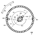
図5は、発光素子及び受光素子の配置関係を示す説明図である。図5は、図4に示す構造をZ方向から見た図である。
信号伝送装置402の発光素子431及び受光素子442は、円筒部材451及び軸部材452のうちの一方、第1実施形態では軸部材452に配置されている。信号伝送装置401の発光素子432及び受光素子441は、円筒部材451及び軸部材452のうちの他方、第1実施形態では円筒部材451に配置されている。より具体的には、発光素子431及び受光素子442は、軸部材452の外周面に固定され、発光素子432及び受光素子441は、円筒部材451の内周面に固定されている。よって、発光素子431と受光素子442は、軸部材452と共に中心軸C1を中心とする円周方向R0に回転する。
円周方向R0は、図5中、時計回りの方向R1と、反時計回りの方向R2との二方向あり、軸部材452は、駆動装置250(図4)により、時計回りの方向R1と反時計回りの方向R2の二方向のうちいずれか一方向に選択的に回転駆動される。
軸部材452に配置された発光素子431の送信相手は、円筒部材451に配置された受光素子441である。円筒部材451に配置された発光素子432の送信相手は、軸部材452に配置された受光素子442である。また、これにより、非接触で通信が行われる。
軸部材452は、例えば直径20[mm]、長さ14[mm]、肉厚2[mm]の白色樹脂を用いた中空の円筒部材である。円筒部材451は、例えば直径64[mm]、長さ14[mm]、肉厚2[mm]の白色樹脂を用いた中空の円筒部材である。円筒部材451の内周面及び軸部材452の外周面は、光が反射する反射面となっている。軸部材452の内側には、発光素子431や受光素子442へ接続された配線が配置されている。
円筒部材451のZ方向の両端部には、図4に示すように、白色樹脂の蓋部材453,454が配置されている。蓋部材453,454は光を閉じ込め、拡散による光減衰を低減する役目があり、蓋部材453,454がない場合と比べ、後述する増幅補正のダイナミックレンジを狭くすることができる。蓋部材453,454には、軸部材452が配置された中心部に直径20[mm]の穴が形成されている。
蓋部材453の穴は、駆動装置250の回転シャフト251が貫通するものである。蓋部材454の穴は、発光素子431や受光素子442に接続された配線を引き出すために用いる。軸部材452を中空とせずに、軸部材452の表面を伝って配線を引き出してもよいが、配線の分だけ軸部材452と円筒部材451との間に隙間が必要となり、隙間から漏れる光による減衰が起こる。軸部材452を中空とすることで隙間からの漏れを低減することができる。
発光素子431、発光素子432、受光素子441及び受光素子442は、無線伝送路となる同一の空間に配置されており、省スペース化が図られている。これにより、ロボットアーム201の小型化を実現することができ、また、軽量化を図ることができるので、ロボットアーム201の制御性が向上する。
第1実施形態では、発光素子431、発光素子432、受光素子441及び受光素子442は、回転シャフト251の回転軸である中心軸C1の延びるZ方向において同一位置に、即ち中心軸C1の延びるZ方向において同じ面内に配置されている。
図5に示すように、軸部材452において、発光素子431と受光素子442とが重ならないように、発光素子431と受光素子442とが円周方向R0において異なる位置に配置されている。同様に、円筒部材451において、発光素子432と受光素子441とが重ならないように、発光素子432と受光素子441とが円周方向R0において異なる位置に配置されている。
ここで、Z方向から見て、中心軸C1から発光素子431の中心に延びる直線L1と中心軸C1から受光素子442の中心に延びる直線L2との成す角の角度(第1の角度)を角度θ1とする。また、Z方向から見て、中心軸C1から発光素子432の中心に延びる直線L3と中心軸C1から受光素子441の中心に延びる直線L4との成す角の角度(第2の角度)を角度θ2とする。
発光素子431,432及び受光素子441,442は、Z方向から見て、角度θ1と角度θ2とが等しくなる位置に配置されている。第1実施形態では、角度θ1,θ2は、180度である。このように、軸部材452に固定された発光素子431と受光素子442との位置関係と、円筒部材451に固定された発光素子432と受光素子441との位置関係とが180度で対称となっている。
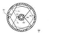
図6Aは、発光素子と受光素子とが対向している状態を基準とし、基準に対する軸部材の回転角度が0度の状態を示す説明図、図6Bは、基準に対する軸部材の回転角度が180度の状態を示す説明図である。
円筒部材451側の信号伝送装置401から軸部材452側の信号伝送装置402への通信を上り通信とし、発光素子432から受光素子442への上り通信の光路をPUで表す。また、軸部材452側の信号伝送装置402から円筒部材451側の信号伝送装置401への通信を下り通信とし、発光素子431から受光素子441への下り通信の光路をPDで表す。
図6Aに示すように、軸部材452の回転角度が0度のとき、発光素子431と受光素子441、発光素子432と受光素子442が、それぞれ対向している。よって、発光素子431と受光素子441、発光素子432と受光素子442が最も近接しており、光路PU,PDが最も短く、上り通信、下り通信の双方とも光の減衰量が最も小さく、受光素子441,442にて受光される受光強度が最も高い。
一方、図6Bに示すように、軸部材452の回転角度が180度のとき、発光素子431と受光素子441、発光素子432と受光素子442が、それぞれ反対側を向いている。よって、光路PU,PDが最も長く、上り通信、下り通信の双方とも光の減衰量が最も大きく、受光素子441,442にて受光される受光強度が最も低い。
図7は、第1実施形態における軸部材452の回転角度に対する各受光素子441,442の受光強度の相対値を示すグラフである。図7において、受光素子442(上り通信)の受光強度を実線で示し、受光素子441(下り通信)の受光強度を破線で示す。軸部材452側の発光素子431と受光素子442との位置関係と、円筒部材451側の発光素子432と受光素子441との位置関係とが対称となっている。即ち角度θ1と角度θ2とが180度で等しい。このため、図7に示すように、軸部材452の回転角度に対する受光素子441の受光強度の変化と、軸部材452の回転角度に対する受光素子442の受光強度の変化が等しい。
角度θ1,θ2を180度とすることで、発光素子431から受光素子442に伝わる光の強度が最も低くなり、発光素子432から受光素子441に伝わる光の強度が最も低くなる。また、受光素子442の受光感度は、発光素子432が発した光を受光する強度に対して、妨害光となる発光素子431が発した光を受光する強度の比と相関がある。同様に、受光素子441の受光感度は、発光素子431が発した光を受光する強度に対して、妨害光となる発光素子432が発した光を受光する強度の比と相関がある。よって、角度θ1,θ2を180度とすることで、各受光素子441,442の受光感度が最も高くなる。
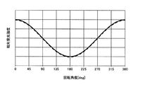
図8は、発光素子432の発光強度を一定とした場合において、軸部材452の回転角度に対する受光素子442の受光強度の測定結果を示すグラフである。図8において、横軸が軸部材452の回転角度、縦軸が受光素子442の相対受光強度である。発光素子431と受光素子441とが対向して最も近接する0度のときに対し、最も遠くなる180度では受光強度が20[dB]低下している。角度θ1,θ2が共に180度であるので、受光素子442においても受光素子441と同じ受光強度となる。
第1実施形態では、図3に示すように、送信部411は、送信回路501と、パイロット信号重畳回路502と、を有して構成される。送信部412は、送信回路511と、増幅量調整回路512と、を有して構成される。受信部421は、受信回路521と、パイロット信号検出回路522と、増幅量調整回路523と、を有して構成される。受信部422は、受信回路531で構成される。
まず、下り通信について説明する。送信回路501は、信号制御装置406から送信対象であるローレベル又はハイレベルの第1のデジタル信号(シングルエンド信号)である電気信号の入力を受ける。
パイロット信号重畳回路502は、入力を受けた電気信号とは異なる周波数帯域のパイロット信号(例えば所定周波数の正弦波)を生成する。このパイロット信号の振幅は一定とする。送信回路501は、デジタル信号にパイロット信号を重畳させた電気信号を生成する。
図9Aは、送信回路501が信号制御装置406から入力を受けたデジタル信号を示す波形図である。図9Bは、パイロット信号重畳回路502が生成したパイロット信号を示す波形図である。図9Cは、デジタル信号にパイロット信号を重畳させて生成した電気信号を示す波形図である。
図9Aに示すように、送信回路501が入力する信号は、第1のデジタル信号であるデジタル信号S1であり、ハイレベルの電圧が例えば0.4[V]、ローレベルの電圧が例えば0である。パイロット信号重畳回路502は、図9Bに示すように、デジタル信号S1のハイレベルの電圧よりも低い電圧の振幅、例えば0.05[V]の振幅のパイロット信号SPを生成する。
図9Cに示すように、送信回路501は、デジタル信号S1にパイロット信号SPを重畳させた電気信号ST1を生成して発光素子431に出力(印加)する。ここで、第1実施形態では、デジタル信号S1がローレベルの状態であっても発光素子431を発光させるために、バイアスした電気信号ST1を発光素子431に出力(印加)する。例えば、1.1[V]バイアスする。ハイレベルとローレベルとの中間電圧は、1.3[V]である。なお、送信回路501がデジタル信号S1をバイアスするものとしたが、信号制御装置406が行ってもよい。
発光素子431は、送信部411にて生成された電気信号ST1に応じた強度の光信号(無線信号)を受光素子441に送信する。つまり、発光素子431は、送信部411にて生成された電気信号ST1の強度(電圧)に応じた強度で発光する。発光素子431から出射された光は、軸部材452と円筒部材451との間の空間を伝搬し、受光素子441に到達する。受光素子441は、発光素子から送信された光信号(無線信号)を受光(受信)する。
受信回路521は、受光素子441にて受光(受信)された光(無線信号)の強度に応じた電気信号を生成する。この電気信号には、デジタル信号成分と、パイロット信号成分とが含まれている。そして、パイロット信号成分は、デジタル信号成分と同様、軸部材452の回転角度に応じて減衰する。
パイロット信号検出回路522は、フィルター回路で構成され、受信回路521から出力された電気信号からパイロット信号成分を検出し、その検出結果であるパイロット信号成分の強度を増幅量調整回路523へ出力する。第1実施形態では、電気信号(パイロット信号成分も含む)の強度とは、電圧のことである。
増幅量調整回路523は、パイロット信号成分の強度と、予め定めた基準強度(基準電圧)とを比較し、基準強度に対するパイロット信号成分の強度の減衰量に応じて、受信回路521が入力を受けた電気信号の強度を増幅する。具体的には、増幅量調整回路523は、減衰量を相殺するように、減衰量が大きいほど大きい増幅量で電気信号の強度を増幅する。このように、パイロット信号成分の減衰量の分だけ受信回路521で得られた電気信号の受信強度を増幅する。これにより、軸部材452の回転角度に応じて光強度の減衰量が変化しても、受信部421の受信回路521からはハイレベルとローレベルが安定した電気信号が出力される。増幅された電気信号は、信号制御装置405に出力され、信号制御装置405にて論理判別が行われる。これにより、信号制御装置405にて判別されるデータ(論理0,1)に誤りが生じるのを防止することができる。なお、信号制御装置405の論理判別に支障がなければ、受信部421から出力される電気信号にパイロット信号成分が重畳されていてもよい。よって、第1実施形態では、パイロット信号成分を分離する分離回路を受信回路521の後段に配置する必要がない。
次に、上り通信について説明する。送信回路511は、信号制御装置405から送信対象であるローレベル又はハイレベルの第2のデジタル信号(シングルエンド信号)である電気信号の入力を受ける。
第1実施形態では、パイロット信号検出回路522は、パイロット信号成分の強度を送信部412の増幅量調整回路512へ出力する。増幅量調整回路512は、パイロット信号成分の強度と予め定めた基準強度と比較し、基準強度に対するパイロット信号成分の強度の減衰量に応じて、送信回路511が入力したデジタル信号の強度を増幅する。具体的には、増幅量調整回路512は、減衰量を相殺するように、減衰量が大きいほど大きい増幅量で電気信号の強度を増幅する。
つまり、角度θ1,θ2が共に180度であるため、発光素子432から送信され受光素子442にて受信される光は、発光素子431から送信され受光素子441にて受信される光と同様の減衰傾向にある。よって、ある瞬間において、下り通信における光信号の減衰量と上り通信における光信号の減衰量は等しい。したがって、第1実施形態では、下り通信において受信部421で電気信号を増幅したのと同様に、上り通信において送信部412で電気信号を増幅する。このように増幅により生成された電気信号は、発光素子432へ出力(印加)される。
発光素子432は、送信部412にて生成された電気信号に応じた強度の光信号(無線信号)を受光素子442に送信する。つまり、発光素子432は、送信部412にて生成された電気信号の強度(電圧)に応じた強度で発光する。発光素子432から出射された光は、軸部材452と円筒部材451との間の空間を伝搬し、受光素子442に到達する。受光素子442は、発光素子から送信された光信号(無線信号)を受光(受信)する。
受信回路531は、受光素子442にて受光(受信)された光(無線信号)の強度に応じた電気信号を生成する。
受光素子442で受光した光信号は、空間を伝搬した際の減衰を受けているが、送信部412で増幅をしているため、その減衰が相殺されている。したがって、軸部材452の回転に伴う光の減衰の影響を受けずに受光素子442にて安定した強度の光信号が受信される。これにより、軸部材452の回転角度に応じて光強度の減衰量が変化しても、受信部422の受信回路531からはハイレベルとローレベルが安定した電気信号が信号制御装置406に出力される。これにより、信号制御装置406にて判別されるデータ(論理0,1)に誤りが生じるのを防止することができる。
以上、第1実施形態によれば、軸部材452の回転により光信号が減衰を受けても、安定した双方向通信が可能となる。また、第1実施形態によれば、上り通信では、下り通信におけるパイロット信号の検出結果を用いて信号を増幅しているため、下り通信と同様のパイロット信号重畳回路及びパイロット信号検出回路を必要としない。即ち、送信部412では、パイロット信号重畳回路を省略することができ、受信部422では、パイロット信号検出回路を省略することができる。このような簡単な構成で双方向通信においてデータが誤って判別されるのを防止することができる。
なお、第1実施形態では、下り通信においてパイロット信号の送受信を行う場合について説明したが、これに限定するものではなく、上り通信においてパイロット信号の送受信を行ってもよい。この場合は、下り通信を行う送信部411及び受信部421においてパイロット信号重畳回路及びパイロット信号検出回路を省略することができる。しかし、回転側にパイロット信号検出回路と2つの増幅量調整回路が必要となり、回転側の回路実装面積や回路の消費電力が大きくなる。一般にロボットアーム201の回転関節のような、回転側の方がサイズや電力に制約があるため、下り通信においてパイロット信号の送受信を行う方が有効である。
また、例えば固定側の受光素子において、固定側の発光素子がローを送信した場合の受光強度が、回転側の発光素子がハイを送信した場合の受光強度を上回るような場合は、固定側の受光素子におけるロー/ハイ判別がしにくくなる場合がある。固定側の発光素子と固定側の受光素子を180度の位置に配置したことにより、固定側の発光素子の光を固定側の受光素子で受光しやすいため、上記の問題が起こりやすいが、回転側の受光素子は回転側の発光素子の光を受けにくい。よって、上記の問題を回避するためには、回転側の発光素子431にパイロット信号を重畳させるようにし、固定側の発光素子432がローのときは、固定側の発光素子432を光らないようにすればよい。以上のことからも、第1実施形態の構成が有効である。
また、発光素子と受光素子との位置関係を角度θ1,θ2で表現し、それぞれの角度θ1,θ2を180度とした場合について説明したが、角度θ1,θ2は、受光強度の変化が0~-6[dB]の範囲内で180度に対して誤差があってもよい。例えば受光素子441,442の受光面の1辺が5[mm]、軸部材452と円筒部材451の間の径方向の間隔が20[mm]の場合、角度θ1,θ2は、減衰量が-6[dB]未満となる173度~187度の範囲であればよい。なお、角度θ1,θ2のずれ量が分かっていれば、その分だけ増幅量を調整してもよい。
[第2実施形態]
次に、第2実施形態に係る双方向通信装置について説明する。図10Aは、第2実施形態における発光素子及び受光素子の配置関係を示す説明図である。なお、第2実施形態において、第1実施形態と同様の構成については説明を省略する。第2実施形態の双方向通信装置では、発光素子431と受光素子442との配置関係、及び発光素子432と受光素子442との配置関係が第1実施形態と異なる。
次に、第2実施形態に係る双方向通信装置について説明する。図10Aは、第2実施形態における発光素子及び受光素子の配置関係を示す説明図である。なお、第2実施形態において、第1実施形態と同様の構成については説明を省略する。第2実施形態の双方向通信装置では、発光素子431と受光素子442との配置関係、及び発光素子432と受光素子442との配置関係が第1実施形態と異なる。
具体的には、第1実施形態では、角度θ1,θ2が共に180度の場合について説明したが、第2実施形態では、角度θ1,θ2が共に90度である。そして、第2実施形態では、回転シャフト251の回転方向の二方向について、即ち円周方向R0の二方向R1,R2について、発光素子431から受光素子442へ向かう方向R2と、発光素子432から受光素子441へ向かう方向R1とが反対である。
図10Bは、発光素子と受光素子とが対向している状態を示す説明図である。第1実施形態と同様、発光素子431と受光素子441が対向しているとき、発光素子432と受光素子442も対向している。したがって、発光素子431と受光素子441、発光素子432と受光素子442が最も近接しており、光路PU,PDが最も短い。よって、第1実施形態と同様、上り通信、下り通信の双方とも光の減衰量が最も小さく、受光素子441,442にて受光される受光強度が最も高い。
この状態から軸部材452が180度回転したとき、発光素子431と受光素子441、発光素子432と受光素子442が、それぞれ反対側を向くことになる。したがって、第1実施形態と同様、上り通信、下り通信の双方とも光の減衰量が最も大きく、受光素子441,442にて受光される受光強度が最も低い。
第1実施形態と同様、軸部材452の回転角度に対する受光素子441の受光強度の変化と、軸部材452の回転角度に対する受光素子442の受光強度の変化が等しく、図7に示すようになる。したがって、各送信部411,412及び各受信部421,422は、第1実施形態と同様の構成である(図3参照)。その際、受信部421は、パイロット信号成分の減衰量が大きいほど大きい増幅量で受信した電気信号の強度を増幅すればよく、送信部412は、パイロット信号成分の減衰量が大きいほど大きい増幅量で送信する電気信号の強度を増幅すればよい。以上、第2実施形態においても、第1実施形態と同様、軸部材452の回転角度によらず双方向通信を安定して行うことができる。
なお、発光素子と受光素子との位置関係を角度θ1,θ2で表現し、それぞれの角度θ1,θ2を90度とした場合について説明したが、角度θ1,θ2は、受光強度の変化が0~-6[dB]の範囲内で90度に対して誤差があってもよい。
また、角度θ1,θ2は、90度に限定するものではなく、0度よりも大きく180度よりも小さい角度であっても、同じ角度であれば同様の作用効果を奏する。
[第3実施形態]
次に、第3実施形態に係る双方向通信装置について説明する。図11は、第3実施形態における発光素子及び受光素子の配置関係を示す説明図である。なお、第3実施形態において、第1,第2実施形態と同様の構成については説明を省略する。第3実施形態の双方向通信装置では、発光素子431と受光素子442との配置関係、及び発光素子432と受光素子442との配置関係が第1,第2実施形態と異なる。更に第3実施形態では、第2の送信部の機能が第1,第2実施形態と異なる。
次に、第3実施形態に係る双方向通信装置について説明する。図11は、第3実施形態における発光素子及び受光素子の配置関係を示す説明図である。なお、第3実施形態において、第1,第2実施形態と同様の構成については説明を省略する。第3実施形態の双方向通信装置では、発光素子431と受光素子442との配置関係、及び発光素子432と受光素子442との配置関係が第1,第2実施形態と異なる。更に第3実施形態では、第2の送信部の機能が第1,第2実施形態と異なる。
即ち、第1実施形態では、角度θ1,θ2が共に180度の場合について説明したが、第3実施形態では、角度θ1,θ2が共に90度である。そして、第3実施形態では、回転シャフト251の回転方向の二方向について、即ち円周方向R0の二方向R1,R2について、発光素子431から受光素子442へ向かう方向R1と、発光素子432から受光素子441へ向かう方向R1とが同一である。
図12Aは、発光素子と受光素子との2つペアのうち、一方のペアが対向している状態を示す説明図である。図12Bは、発光素子と受光素子との2つペアのうち、他方のペアが対向している状態を示す説明図である。即ち、図12Bには、図12Aの状態に対して軸部材452を180度回転させた状態を図示している。
図12Aに示すように、発光素子432と受光素子442とが対向しているとき、発光素子431と受光素子441とは向きが反対となっている。この場合、発光素子432と受光素子442とが最も近接しており、光路PUは最も短くなるが、光路PDは最も長くなる。したがって、上り通信における光の減衰量は最も小さいが、下り通信における光の減衰量は最も大きい。そのため、受光素子442にて受光される受光強度は最も高いが、受光素子441にて受光される受光強度は最も低い。
一方、図12Bに示すように、発光素子431と受光素子441とが対向しているとき、発光素子432と受光素子442とは向きが反対となっている。この場合、発光素子431と受光素子441とが最も近接しており、光路PDは最も短くなるが、光路PUは最も長くなる。したがって、下り通信における光の減衰量は最も小さいが、上り通信における光の減衰量は最も大きい。そのため、受光素子441にて受光される受光強度は最も高いが、受光素子442にて受光される受光強度は最も低い。
図13は、第3実施形態における軸部材452の回転角度に対する各受光素子441,442の受光強度の相対値を示すグラフである。図13において、受光素子442(上り通信)の受光強度を実線で示し、受光素子441(下り通信)の受光強度を破線で示す。軸部材452側の発光素子431と受光素子442との位置関係と、円筒部材451側の発光素子432と受光素子441との位置関係とが対称となっている。即ち角度θ1と角度θ2とが90度で等しい。しかし、発光素子431から受光素子442へ向かう方向R1と、発光素子432から受光素子441へ向かう方向R1とが同一である。このため、図13に示すように、軸部材452の回転角度に対する受光素子441の受光強度の変化(破線)と、軸部材452の回転角度に対する受光素子442の受光強度の変化(実線)との関係が逆、即ち破線と実線とが逆位相となっている。
図14は、第3実施形態に係る双方向通信装置を示すブロック図である。双方向通信装置400Aは、固定側であるリンク210(図1)に設けられた信号伝送装置401Aと、回転側であるリンク211(図1)に設けられた信号伝送装置402とを有する。信号伝送装置402については第1実施形態で説明した図3と同様の構成である。
信号伝送装置401Aは、上述した発光素子432及び受光素子441と、第2の送信部である送信部412Aと、第1実施形態と同様の受信部421及び信号制御装置405と、を有する。送信部412Aは、送信回路511と、増幅量調整回路512と、反転回路513とを有する。即ち、第3実施形態の送信部412Aは、第1実施形態で説明した送信部412の構成に反転回路513を追加したものである。
反転回路513は、パイロット信号検出回路522で検出したパイロット信号成分の強度を反転して増幅量調整回路512へ出力するものである。具体的には、反転回路513は、第1実施形態で説明した基準強度からパイロット信号成分の強度を差し引いた反転強度を増幅量調整回路512へ出力する。よって、増幅量調整回路512は、反転強度と基準強度とを比較し、反転強度に応じて送信回路511が入力したデジタル信号の強度を増幅する。このように、増幅量調整回路512は、基準強度に対するパイロット信号成分の強度の減衰量に応じて、増幅量調整回路523とは反転した増幅量で、デジタル信号の強度を増幅する。具体的には、増幅量調整回路512は、反転強度が大きいほど大きい増幅量で電気信号の強度を増幅する。換言すると、増幅量調整回路512は、パイロット信号成分の強度の減衰量が小さいほど大きい増幅量で送信回路511が信号制御装置405から入力を受けた電気信号の強度を増幅する。
このように、回転角度に対する受光強度の変化が上り通信、下り通信で反転していても、角度θ1,θ2が等しければ、第1実施形態と同様に、増幅補正が可能となる。
受光素子442では、下り通信の強度と反転した強度の光を受光することとなる。受光素子442で受光した光信号は、空間を伝搬した際の減衰を受けているが、送信部412Aでは下り通信に対して反転した増幅量で増幅されるため、その減衰が相殺されている。したがって、軸部材452の回転に伴う光の減衰の影響を受けずに受光素子442にて安定した強度の光信号が受信される。これにより、軸部材452の回転角度に応じて光強度の減衰量が変化しても、受信部422の受信回路531からはハイレベルとローレベルが安定した電気信号が信号制御装置406に出力される。これにより、信号制御装置406にて判別されるデータ(論理0,1)に誤りが生じるのを防止することができる。
以上、第3実施形態によれば、軸部材452の回転により光信号が減衰を受けても、安定した双方向通信が可能となる。また、第3実施形態によれば、上り通信では、下り通信におけるパイロット信号の検出結果を用いて信号を増幅しているため、下り通信と同様のパイロット信号重畳回路及びパイロット信号検出回路を必要としない。即ち、送信部412Aでは、パイロット信号重畳回路を省略することができ、受信部422では、パイロット信号検出回路を省略することができる。このような簡単な構成で双方向通信においてデータが誤って判別されるのを防止することができる。
なお、第3実施形態では、下り通信においてパイロット信号の送受信を行う場合について説明したが、これに限定するものではなく、上り通信においてパイロット信号の送受信を行ってもよい。
また、発光素子と受光素子との位置関係を角度θ1,θ2で表現し、それぞれの角度θ1,θ2を90度とした場合について説明したが、角度θ1,θ2は、受光強度の変化が0~-6[dB]の範囲内で90度に対して誤差があってもよい。
また、角度θ1,θ2は、90度に限定するものではなく、0度よりも大きく180度よりも小さい角度であっても、同じ角度であれば同様の作用効果を奏する。
本発明は、以上説明した実施形態に限定されるものではなく、本発明の技術的思想内で多くの変形が可能である。また、実施形態に記載された効果は、本発明から生じる最も好適な効果を列挙したに過ぎず、本発明による効果は、実施形態に記載されたものに限定されない。
上述の実施形態では、光通信を行う場合について説明したが、これに限定するものではない。光通信を行うのが好適であるが、電波による通信や、電界又は磁界による通信を行う場合であってもよい。例えば、送信素子及び受信素子がアンテナ等の共振部で構成され、送信部が変調回路、受信部が復調回路を有して構成されていてもよい。
また、上述の実施形態では、双方向通信装置がロボットアームの回転関節に搭載されている場合について説明したが、これに限定するものではなく、ロボットハンド等のエンドエフェクタの回転部に双方向通信装置が搭載されていてもよい。また、回転関節に限らず、ロボットにおいて無線通信が必要となる部分に双方向通信装置を搭載してもよい。更に、双方向通信装置は、ロボット装置に限らず、バス通信において無線通信を行う必要がある機器全般に搭載することが可能である。
この出願は2016年6月9日に出願された日本国特許出願第2016-115662からの優先権を主張するものであり、その内容を引用してこの出願の一部とするものである。
100…ロボット装置(機器)、201…ロボットアーム、400…双方向通信装置、411…送信部(第1の送信部)、412…送信部(第2の送信部)、421…受信部(第1の受信部)、422…受信部(第2の受信部)、431…発光素子(第1の送信素子)、432…発光素子(第2の送信素子)、441…受光素子(第1の受信素子)、442…受光素子(第2の受信素子)
Claims (17)
- 第1の部材に設けられた第1の送信部と、第2の部材に設けられ、前記第1の送信部との相対距離が変化する第1の受信部と、を有する無線通信装置であって、
前記第1の送信部は、送信対象である第1のデジタル信号にパイロット信号を重畳させた第1の電気信号を生成して、前記第1の電気信号に応じた強度の第1の無線信号を送信し、
前記第1の受信部は、受信した前記第1の無線信号の強度に応じた第2の電気信号を生成して、前記第2の電気信号からパイロット信号成分を検出し、
前記パイロット信号成分の減衰量に応じて前記第2の電気信号を増幅することを特徴とする無線通信装置。 - さらに前記第1の部材が第2の受信部、前記第2の部材が前記第2の受信部との相対距離が変化する第2の送信部、をそれぞれ備えており、
前記第2の送信部は、前記減衰量に応じて、送信対象である第2のデジタル信号を増幅させた第3の電気信号を生成して、前記第3の電気信号に応じた強度の第2の無線信号を送信し、
前記第2の受信部は、受信した前記第2の無線信号の強度に応じた第4の電気信号を生成することを特徴とする請求項1に記載の無線通信装置。 - 前記第1の部材と前記第2の部材のいずれか一方の部材がシャフトに固定されており、他方の部材に対して相対的に回転する部材であることを特徴とする請求項2に記載の無線通信装置。
- 前記第1の送信部が第1の送信素子を有し、前記第1の受信部が第1の受信素子を有しており、
前記第1の送信素子と前記第1の受信素子とは、前記シャフトの回転軸の延びる方向において同じ面内に配置されていることを特徴とする請求項3に記載の無線通信装置。 - 前記第2の送信部が第2の送信素子を有し、前記第2の受信部が第2の受信素子を有しており、
前記第2の送信素子と前記第2の受信素子とは、前記シャフトの回転軸の延びる方向において、前記第1の送信素子および前記第1の受信素子と同じ面内に配置されていることを特徴とする請求項4に記載の無線通信装置。 - 前記第1の送信素子、前記第2の送信素子、前記第1の受信素子及び前記第2の受信素子は、前記回転軸の延びる方向から見て、前記回転軸から前記第1の送信素子に延びる直線と前記回転軸から前記第2の受信素子に延びる直線との成す角の第1の角度と、前記回転軸から前記第2の送信素子に延びる直線と前記回転軸から前記第1の受信素子に延びる直線との成す角の第2の角度とが等しくなる位置に配置されていることを特徴とする請求項5に記載の無線通信装置。
- 前記第1の角度及び前記第2の角度が180度であることを特徴とする請求項6に記載の無線通信装置。
- 前記第2の送信部は、前記減衰量が大きいほど大きい増幅量で前記第2のデジタル信号の強度を増幅することを特徴とする請求項2乃至7のいずれか1項に記載の無線通信装置。
- 前記シャフトの回転方向の二方向について、前記第1の送信素子から前記第2の受信素子へ向かう方向と、前記第2の送信素子から前記第1の受信素子へ向かう方向とが同一であり、
前記第2の送信部は、前記減衰量が小さいほど大きい増幅量で前記第2のデジタル信号の強度を増幅することを特徴とする請求項6に記載の無線通信装置。 - 前記シャフトの回転方向の二方向について、前記第1の送信素子から前記第2の受信素子へ向かう方向と、前記第2の送信素子から前記第1の受信素子へ向かう方向とが反対であり、
前記第2の送信部は、前記減衰量が大きいほど大きい増幅量で前記第2のデジタル信号の強度を増幅することを特徴とする請求項6に記載の無線通信装置。 - 前記第1の角度及び前記第2の角度が90度であることを特徴とする請求項9又は10に記載の無線通信装置。
- 前記第1の送信素子は、発光する発光素子であり、
前記第1の受信素子は、受光する受光素子であることを特徴とする請求項1乃至11のいずれか1項に記載の無線通信装置。 - 前記第2の送信素子は、発光する発光素子であり、
前記第2の受信素子は、受光する受光素子であることを特徴とする請求項5、6、7、9、10及び11のいずれか1項に記載の無線通信装置。 - 前記第1の部材は、円筒部材であり、
前記第2の部材は、前記円筒部材の内側に前記円筒部材と同軸に配置された軸部材であることを特徴とする請求項1乃至13のいずれか1項に記載の無線通信装置。 - 請求項1乃至14のいずれか1項に記載の無線通信装置と、
前記第2の部材を回転駆動する駆動装置と、を備えた機器。 - 前記機器が、複数の関節を有し、前記複数の関節うち先端の関節にてハンドが着脱可能なロボットアームを備え、
前記無線通信装置及び前記駆動装置は、前記複数の関節の少なくとも1つに搭載されていることを特徴とする請求項15に記載の機器。 - 前記機器が、ハンドと複数の関節を有するロボットアームとを備え、
前記無線通信装置は前記複数の関節の少なくとも1つに設置されていることを特徴とする請求項15に記載の機器。
Priority Applications (1)
| Application Number | Priority Date | Filing Date | Title |
|---|---|---|---|
| US16/204,288 US10630390B2 (en) | 2016-06-09 | 2018-11-29 | Wireless communication device and apparatus |
Applications Claiming Priority (2)
| Application Number | Priority Date | Filing Date | Title |
|---|---|---|---|
| JP2016-115662 | 2016-06-09 | ||
| JP2016115662A JP6833352B2 (ja) | 2016-06-09 | 2016-06-09 | 無線通信装置及び機器 |
Related Child Applications (1)
| Application Number | Title | Priority Date | Filing Date |
|---|---|---|---|
| US16/204,288 Continuation US10630390B2 (en) | 2016-06-09 | 2018-11-29 | Wireless communication device and apparatus |
Publications (1)
| Publication Number | Publication Date |
|---|---|
| WO2017212947A1 true WO2017212947A1 (ja) | 2017-12-14 |
Family
ID=60579018
Family Applications (1)
| Application Number | Title | Priority Date | Filing Date |
|---|---|---|---|
| PCT/JP2017/019677 Ceased WO2017212947A1 (ja) | 2016-06-09 | 2017-05-26 | 無線通信装置及び機器 |
Country Status (3)
| Country | Link |
|---|---|
| US (1) | US10630390B2 (ja) |
| JP (1) | JP6833352B2 (ja) |
| WO (1) | WO2017212947A1 (ja) |
Families Citing this family (5)
| Publication number | Priority date | Publication date | Assignee | Title |
|---|---|---|---|---|
| DE112018005298A5 (de) * | 2017-09-19 | 2020-06-18 | Osram Gmbh | System zur Übertragung von Daten |
| FR3082687B1 (fr) * | 2018-06-18 | 2021-10-01 | Safran Nacelles | Dispositif et procede de communication de donnees dans un sous-ensemble d’aeronef |
| JP7286389B2 (ja) * | 2019-04-15 | 2023-06-05 | キヤノン株式会社 | 無線通信装置、無線通信システムおよび通信方法 |
| KR102794238B1 (ko) | 2019-12-17 | 2025-04-14 | 삼성전자주식회사 | 근거리 무선 통신 리더기, 그것의 동작 방법, 및 그것을 포함하는 전자 장치 |
| CN112491444B (zh) * | 2020-11-16 | 2022-03-11 | 广州保得威尔电子科技股份有限公司 | 一种二总线信号中继器 |
Citations (4)
| Publication number | Priority date | Publication date | Assignee | Title |
|---|---|---|---|---|
| JPH05136740A (ja) * | 1991-11-15 | 1993-06-01 | Canon Inc | 光空間通信装置 |
| JP2003241003A (ja) * | 2002-02-19 | 2003-08-27 | Yazaki Corp | 信号伝送装置 |
| JP2007038360A (ja) * | 2005-08-04 | 2007-02-15 | Hitachi High-Tech Control Systems Corp | 多関節搬送装置及びそれを用いた半導体製造装置 |
| JP2013034043A (ja) * | 2011-08-01 | 2013-02-14 | Canon Inc | 信号伝送装置 |
Family Cites Families (6)
| Publication number | Priority date | Publication date | Assignee | Title |
|---|---|---|---|---|
| JPH0316050A (ja) | 1989-06-13 | 1991-01-24 | Mitsubishi Electric Corp | 光ディスク記録再生装置 |
| US7239811B2 (en) * | 2003-02-18 | 2007-07-03 | Victor Company Of Japan, Ltd. | Optical-axis directional indicating apparatus for optical communication |
| JP2006108337A (ja) * | 2004-10-05 | 2006-04-20 | Chubu Nippon Maruco Kk | 非接触コネクタ |
| PL1996376T3 (pl) * | 2006-03-03 | 2016-12-30 | Programowalny robot i interfejs użytkownika | |
| JP4747208B2 (ja) | 2008-06-03 | 2011-08-17 | キヤノン株式会社 | 電磁界計測装置および方法 |
| JP5631230B2 (ja) | 2011-02-02 | 2014-11-26 | キヤノン株式会社 | 電源回路 |
-
2016
- 2016-06-09 JP JP2016115662A patent/JP6833352B2/ja active Active
-
2017
- 2017-05-26 WO PCT/JP2017/019677 patent/WO2017212947A1/ja not_active Ceased
-
2018
- 2018-11-29 US US16/204,288 patent/US10630390B2/en active Active
Patent Citations (4)
| Publication number | Priority date | Publication date | Assignee | Title |
|---|---|---|---|---|
| JPH05136740A (ja) * | 1991-11-15 | 1993-06-01 | Canon Inc | 光空間通信装置 |
| JP2003241003A (ja) * | 2002-02-19 | 2003-08-27 | Yazaki Corp | 信号伝送装置 |
| JP2007038360A (ja) * | 2005-08-04 | 2007-02-15 | Hitachi High-Tech Control Systems Corp | 多関節搬送装置及びそれを用いた半導体製造装置 |
| JP2013034043A (ja) * | 2011-08-01 | 2013-02-14 | Canon Inc | 信号伝送装置 |
Also Published As
| Publication number | Publication date |
|---|---|
| US20190097731A1 (en) | 2019-03-28 |
| JP2017220871A (ja) | 2017-12-14 |
| JP6833352B2 (ja) | 2021-02-24 |
| US10630390B2 (en) | 2020-04-21 |
Similar Documents
| Publication | Publication Date | Title |
|---|---|---|
| WO2017212947A1 (ja) | 無線通信装置及び機器 | |
| US10109183B1 (en) | Interface for transferring data between a non-rotating body and a rotating body | |
| JP7630967B2 (ja) | 無線伝送システム、制御方法、およびプログラム | |
| US10122416B2 (en) | Interface for transferring power and data between a non-rotating body and a rotating body | |
| US10784926B2 (en) | Signal transmission apparatus, signal transmission system, and instrument | |
| EP2203985B9 (en) | Transmission lines applied to contact free slip rings | |
| US8301030B2 (en) | Rotary joint | |
| EP3852235A1 (en) | Contactless power supply and data communication device, and system having rotation-drive unit, using same | |
| JP7071142B2 (ja) | 通信システム、通信装置および通信方法 | |
| WO2018125709A1 (en) | Interface for transferring power and data between a non-rotating body and a rotating body | |
| JP2017220871A5 (ja) | 無線通信装置及び機器 | |
| JP2016003947A (ja) | エンコーダ装置、駆動装置、ステージ装置、及びロボット装置 | |
| JP2020504594A (ja) | 非回転体と回転体との間で電力及びデータを伝送するためのインターフェース | |
| JP2008282188A (ja) | 通信システム | |
| JP2010074253A (ja) | 双方向光通信装置 | |
| JP2018167386A (ja) | ロボット | |
| US11411462B1 (en) | Support assembly for rotating body | |
| JP2017020902A (ja) | ロータリージョイントおよびレーダ装置 | |
| JP2002280239A (ja) | 回転型非接触コネクタ及び非回転型非接触コネクタ | |
| CN117692064A (zh) | 一种带挡光圈的非接触光通信滑环及其光器件布置方法 | |
| JP6273787B2 (ja) | 通信装置、通信システムおよびアンテナ構造体 | |
| JPH1160076A (ja) | 伝送ケーブル用リール | |
| JP2004103686A (ja) | 光ロータリトランス | |
| US9906292B2 (en) | Multiple order connectors for contactless communication devices and methods for using the same | |
| JP2021083029A (ja) | ロータリージョイント |
Legal Events
| Date | Code | Title | Description |
|---|---|---|---|
| 121 | Ep: the epo has been informed by wipo that ep was designated in this application |
Ref document number: 17810127 Country of ref document: EP Kind code of ref document: A1 |
|
| NENP | Non-entry into the national phase |
Ref country code: DE |
|
| 122 | Ep: pct application non-entry in european phase |
Ref document number: 17810127 Country of ref document: EP Kind code of ref document: A1 |