WO2017212908A1 - ステージ装置およびリニアアクチュエータ - Google Patents
ステージ装置およびリニアアクチュエータ Download PDFInfo
- Publication number
- WO2017212908A1 WO2017212908A1 PCT/JP2017/019127 JP2017019127W WO2017212908A1 WO 2017212908 A1 WO2017212908 A1 WO 2017212908A1 JP 2017019127 W JP2017019127 W JP 2017019127W WO 2017212908 A1 WO2017212908 A1 WO 2017212908A1
- Authority
- WO
- WIPO (PCT)
- Prior art keywords
- stage
- shaft
- wire
- cross roller
- linear actuator
- Prior art date
- Legal status (The legal status is an assumption and is not a legal conclusion. Google has not performed a legal analysis and makes no representation as to the accuracy of the status listed.)
- Ceased
Links
Images














Classifications
-
- G—PHYSICS
- G02—OPTICS
- G02B—OPTICAL ELEMENTS, SYSTEMS OR APPARATUS
- G02B21/00—Microscopes
- G02B21/24—Base structure
- G02B21/26—Stages; Adjusting means therefor
-
- H—ELECTRICITY
- H02—GENERATION; CONVERSION OR DISTRIBUTION OF ELECTRIC POWER
- H02K—DYNAMO-ELECTRIC MACHINES
- H02K41/00—Propulsion systems in which a rigid body is moved along a path due to dynamo-electric interaction between the body and a magnetic field travelling along the path
- H02K41/02—Linear motors; Sectional motors
- H02K41/03—Synchronous motors; Motors moving step by step; Reluctance motors
- H02K41/031—Synchronous motors; Motors moving step by step; Reluctance motors of the permanent magnet type
-
- H—ELECTRICITY
- H02—GENERATION; CONVERSION OR DISTRIBUTION OF ELECTRIC POWER
- H02K—DYNAMO-ELECTRIC MACHINES
- H02K7/00—Arrangements for handling mechanical energy structurally associated with dynamo-electric machines, e.g. structural association with mechanical driving motors or auxiliary dynamo-electric machines
- H02K7/003—Couplings; Details of shafts
Definitions
- the present invention relates to a stage device and a linear actuator used for driving the stage device.
- a stage device (hereinafter referred to as a microscope stage) used for a microscope places a slide glass to be observed and moves in the x and y directions with respect to the objective lens so that a desired observation region enters the microscope field of view.
- a microscope stage used for pathological diagnosis requires observation at the cell level, high positional management accuracy is required for the microscope stage.
- a manual operation mechanism for manually turning the knobs in the x and y directions is used. It has been broken.
- Patent Document 1 describes an electric stage using a cylindrical linear motor that can be used as a microscope stage. Since this cylindrical linear motor is less likely to generate backlash in principle, the observation position can be automatically controlled with high accuracy in the stage device.
- observation is performed by moving the microscope stage in manual mode.
- the manual mode requires that the observation position can be moved with high precision and fine operability and responsiveness.
- the microscope stage is required to be able to realize an automatic mode in which the stage is moved electrically.
- the position of the region of interest (Region of Interest) observed in the manual mode is stored in, for example, xy coordinates, and can be automatically returned to the stored position quickly and accurately. .
- the electric stage described in Patent Document 1 can realize stage driving in an automatic mode.
- a pseudo manual mode can be realized by driving the electric stage based on an electric signal obtained from a manual operation member such as a joystick or a knob.
- a manual operation member such as a joystick or a knob.
- the fine operation of the user is not reflected with high accuracy and high speed, and the user feels stress. Therefore, regarding the manual mode, it is desirable to use a configuration that converts a user's operation into a stage movement by a mechanical structure.
- an automatic mode mechanism such as the electric stage of Patent Document 1, a mechanism for the manual mode, and a mechanism for switching them are provided. It is possible.
- a stage apparatus that reduces the occurrence of subtle movements of the stage position (observation position) when switching between automatic mode and manual mode.
- a stage apparatus has the following configuration. That is, The first stage, A second stage that moves relatively in a first direction on the surface of the first stage; First driving means for driving a first driven part for moving the second stage relatively in the first direction by a manual driving force; Second driving means for driving a second driven part for relatively moving the second stage in the first direction by an electric driving force; At least a part of the first driven part and the second driven part have a common operating axis.
- occurrence of subtle movement of the stage position (observation position) at the time of switching between the automatic mode and the manual mode is reduced.
- FIG. 3 is a diagram illustrating an example of an appearance of an x stage, a y stage, and a stage base that configure the stage apparatus 100.
- FIG. 3 is a diagram illustrating an example of an appearance of an x stage, a y stage, and a stage base that configure the stage apparatus 100.
- , , , The figure explaining an example of the structure of a linear actuator.
- stacking state of x stage, y stage, and a stage base. The figure which shows the modification regarding attachment of the frame of a linear actuator.
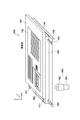
- FIG. 1 is a schematic view showing an appearance of the stage apparatus 100 according to the first embodiment.
- the stage apparatus 100 is used as a microscope stage that places a slide to be observed and moves in the x direction and the y direction with respect to the mirror base of the microscope.
- the stage apparatus 100 is an xy stage having a structure in which a stage base 130, a y stage 120, and an x stage 110 are stacked. Note that the stacking order is not limited to the example of FIG. 1, and the y stage 120 may be provided above the x stage 110. In the stage apparatus 100, the y stage 120 moves relatively on the surface of the stage base 130 in the y direction.
- the x stage 110 moves relatively on the surface of the y stage 120 in the x direction.
- the stage base 130 corresponds to an example of a first stage
- the y stage 120 corresponds to an example of a second stage.
- the x stage 110 corresponds to an example of a third stage.
- the y direction corresponds to an example of the first direction
- the x direction corresponds to an example of the second direction.
- the y stage 120 may be regarded as an example of the first stage
- the x stage 110 may be regarded as an example of the second stage.
- the x direction is an example of the first direction.
- the stage base 130 is fixed to the z base (not shown) of the mirror base of the microscope.
- the y stage 120 is movable on the stage base 130 in the y direction along the y axis cross roller guide 121, and the x stage 110 is moved on the y stage 120 in the x direction along the x axis cross roller guide 111.
- the xy stage capable of moving the position management surface stage 101 formed on the x stage 110 in two directions of the x direction and the y direction with respect to the stage base 130 (relative to the mirror base of the microscope). Is provided.
- the position management surface stage 101 includes an xy scale plate 102 for performing position management of the position management surface stage 101 and a slide placement stage 103 on which a slide is placed.
- the xy stage only needs to be able to mount a slide and move in the xy direction with respect to the objective lens, and the configuration for managing the xy position (such as the position management surface stage 101) is limited to that shown in FIG. Absent.
- the user can move the x stage 110 in the x direction by turning the x knob 161 of the manual knob 160, and can move the y stage 120 in the y direction by turning the y knob 162. Therefore, the user can move the position management surface stage 101 in the xy direction by operating the manual knob 160.
- the y knob 162 corresponds to an example of a first driving unit.
- the x knob 161 corresponds to an example of a third driving unit.
- FIG. 2 is a diagram showing the appearance of each of the x stage 110, the y stage 120, and the stage base 130 that constitute the stage apparatus 100. As shown in FIG.
- an x-axis cross roller guide 111a that is paired with the x-axis cross roller guide 111b disposed in the y stage 120 is disposed.
- a y-axis cross roller guide 121b that is paired with the y-axis cross roller guide 121a disposed on the y stage 120 is disposed.
- the two x-axis cross roller guides 111a are arranged so as to sandwich the two x-axis cross roller guides 111b from the outside, and the two y-axis cross roller guides 121a sandwich the two y-axis cross roller guides 121b from the outside. Is arranged.
- the x stage 110 can move on the surface of the y stage 120 in the x-axis direction.
- the y stage 120 can move on the surface of the stage base 130 in the y-axis direction.
- the y stage 120 is equipped with a drive mechanism for moving the x stage 110 with respect to the y stage in the x direction and a drive mechanism for moving the y stage 120 with respect to the stage base 130 in the y direction.
- the manual drive mechanism 170 drives a driven part (in this embodiment, a wire connected to the x stage) for moving the x stage 110 in the x direction with respect to the y stage 120 by a manual driving force.
- the manual drive mechanism 170 drives a driven part (a wire connected to the stage base 130 in this embodiment) for moving the y stage 120 in the y direction with respect to the stage base 130.
- the rotation operations of the x knob 161 and the y knob 162 are converted into the movement operations of the x wire 173 and the y wire 174 shown in more detail in FIG.
- the movement of the x wire 173 moves the x stage 110 in the x direction with respect to the y stage 120
- the movement of the y wire 174 moves the y stage 120 in the y direction with respect to the stage base 130.
- the y wire 174 corresponds to an example of a first driven part.
- the x wire 173 corresponds to an example of a third driven part.
- the linear actuator 200x for the x direction is a linear actuator that provides a driving force for moving the x stage 110 in the x direction with respect to the y stage 120.
- the y-direction linear actuator 200y is a linear actuator that provides a driving force for moving the y-stage 120 with respect to the stage base 130 in the y-direction. Since the linear actuators 200x and 200y have the same structure, hereinafter, they are collectively referred to as a linear actuator 200. Further, when distinguishing whether the linear actuator 200 is for the x direction or the y direction, x and y are appended to the end of the reference numerals.
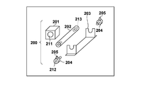
- FIG. 3A to 3D are views for explaining the structure of the linear actuator 200 according to the present embodiment.
- FIG. 3A is a diagram illustrating an upper surface, a front surface, a lower surface, and a side surface of the linear actuator 200.
- FIG. 3B and FIG. 3D are perspective views showing the linear actuator 200 disassembled with components.
- 3c in FIG. 3C is a view for explaining the attachment of the linear actuator 200.
- FIG. 3d of FIG. 3C is a diagram showing a cross section of a part of 3c.
- the linear actuator 200 according to the present embodiment uses a so-called shaft motor (linear motor using a shaft) including an outer packet member 201 and a shaft 202 inserted through a hole penetrating the outer packet member 201.
- the shaft 202 is fixed to the large hole 214 provided in the frame 203 by using the wire connecting portion 204 in a state where the shaft 202 is passed through the through hole 211 of the outer packaging member 201 of the shaft motor.
- the shaft 202 is wire-connected to the frame 203 so that the drive wire 15 (x-wire 173 and y-wire 174 shown in more detail in FIG. 4 and subsequent figures) and the shaft 202 are coaxial. It is fixed by the part 204.
- the linear actuator 200 includes an outer packet member 201, a shaft 202 that is slidably inserted through the through hole 211 of the outer packet member 201, and a wire for fixing the shaft 202 to the frame 203 and connecting a drive wire.
- One of the outer packaging member 201 and the shaft 202 has a coil and the other has a magnet, and the member including the magnet moves relative to the coil by energizing the member having the coil.
- the linear actuator 200 which provides an electric driving force, has a so-called shaft motor (linear motor using a shaft) composed of an outer packet member 201 and a shaft 202 inserted into a hole penetrating the outer packet member 201 when mounted. It is fixed to the frame 203. In the linear actuator 200, the shaft 202 moves in the longitudinal direction (axial direction) in response to application of an electric signal.
- a so-called shaft motor linear motor using a shaft
- the shaft 202 moves in the longitudinal direction (axial direction) in response to application of an electric signal.
- the shaft 202 has a circular cross section, is inserted into the through hole 211 of the outer packaging member 201, and is incorporated into the frame 203 at the time of mounting, and both ends thereof are fixed to the frame 203 by the wire connecting portion 204.
- one end of the wire connection portion 204 is provided with a screw portion corresponding to the screw portion 213 provided at the end portion of the shaft 202, and the other end is provided with a hole portion 212 for fixing the wire.
- a drive wire (an x wire 173 or a y wire 174 described later) is inserted into the hole 212 and tightened from the radial direction with a wire fixing screw 205, whereby the drive wire is connected substantially coaxially with the shaft 202.
- the coaxial means that the central axis of the drive wire and the central axis of the shaft 202 coincide with each other.
- 3A to 3C show the form in which the drive wire is fixed to the hole 212 with the wire fixing screw 205
- the method of fixing the drive wire is not limited to this. Any structure may be adopted as long as the shaft 202 and the drive wire can be fixed coaxially.
- the drive wire may be fixed to the hole 212 by caulking.
- the end of the drive wire is inserted into a cylindrical hole of a cylindrical pin having a cylindrical hole at one end, and the cylindrical pin is fixed to the end of the drive wire with screws or caulking, and the other end of the cylindrical pin is connected to the hole 212.
- And may be fixed with a wire fixing screw 205.
- the outer packaging member 201 is fixed directly to the y stage 120 by an outer packaging member fixing screw 206 or indirectly through an attachment member.
- the frame 203 is fixed directly to the x stage 110 or the stage base 130 by a frame fixing screw 207 or indirectly through an attachment member. According to such a configuration, the frame 203x of the linear actuator 200x in the x direction is fixed with respect to the x stage 110, and the x stage 110 moves with respect to the y stage 120 when the shaft 202x moves in the x direction with respect to the outer packaging member 201x. Move in the x direction. Similarly, the frame 203y of the linear actuator 200y in the y direction is fixed with respect to the stage base 130.
- the outer packaging member 201y corresponds to an example of a second driving unit
- the shaft 202y corresponds to an example of a second driven unit
- the outer packaging member 201x corresponds to an example of a fourth driving unit
- the shaft 202x corresponds to an example of a fourth driven unit.
- the provision form of the linear actuator 200 of this embodiment and the attachment to the stage apparatus 100 are not restricted to the form mentioned above.
- a shaft 202 having wire connecting portions 204 at both ends may be inserted into a large U groove provided in the frame 203 and fixed.
- any configuration can be used as long as the wire is mounted on the stage device so that the manual driving wire and the electric driving shaft 202 are coaxial and the axial direction thereof is parallel to the moving direction of the stage. May be used.
- the manual driving wire is connected to be coaxial with the axis of the shaft 202 at a position on the extension of the axis of the shaft 202.
- the driving wire may not be connected to both ends of the shaft 202.
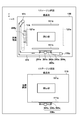
- FIG. 4 is a diagram schematically showing the arrangement of components related to stage driving on the lower surface of the y stage 120 and the upper surface of the stage base 130. Since FIG. 4 is a schematic diagram for explaining the arrangement of the component parts, the size position and shape of the opening provided in the stage and the arrangement position and size of each component part are shown in FIG. It does not necessarily match the configuration diagram of the stage shown.
- the y-axis cross roller guide 121a and the outer member 201y of the linear actuator 200y are fixed to the lower surface of the y stage 120.
- a y wire 174 is hung between the y pulley 172 and the pulley 175a, the linear actuator 200y is disposed so that the y wire 174 and the shaft 202y are coaxial, and the y wire 174 is connected to the wire connecting portion 204y.
- the y pulley 172 rotates in response to a manual operation with respect to the y knob 162, and the y wire 174 is operated by the rotation of the y pulley 172.
- the shaft 202y is fixed to the frame 203y.
- the frame 203y is fixed to the stage base 130 (via a bracket (not shown) if necessary).
- a y-axis cross roller guide 121 b is disposed on the upper surface of the stage base 130.
- the y-axis cross roller guide 121a is configured to sandwich the y-axis cross roller guide 121b, and the y stage 120 is movable in the y direction with respect to the stage base 130.
- the y stage 120 moves in the y direction (along the y-axis cross roller guide 121) with respect to the stage base 130. Since the linear actuator 200y moves the shaft 202y in response to energization of the coil of the outer packaging member 201y, the y stage 120 can be moved in the y direction with respect to the stage base 130 by the driving force of the linear actuator 200y. Further, the manual rotational force of the y knob 162 is converted into the rotational force of the y pulley 172 in the manual drive mechanism 170, and the y wire 174 is moved.
- the y wire 174 is connected to the stage base 130 via the wire connecting portion 204 and the frame 203y, the movement of the y wire 174 moves the stage base 130 relative to the y stage 120 in the y direction. As a result, the y stage 120 moves in the y direction with respect to the stage base 130.
- FIG. 5 is a diagram schematically showing the arrangement of components related to stage driving in the upper surface of the y stage 120 and the x stage 110. 5 is also a schematic diagram for explaining the arrangement of the component parts, as in FIG. 4, the size position and shape of the opening provided in the stage, the arrangement position and size of each component part, etc. Does not necessarily match the configuration diagram of the stage shown in FIG.
- the x-axis cross roller guide 111b and the outer member 201x of the linear actuator 200x are fixed to the upper surface of the y stage 120.
- An x wire 173 is hung between the x pulley 171 and the pulley 175b, the linear actuator 200x is disposed so that the x wire 173 and the shaft 202x are coaxial, and the x wire 173 is connected to the wire connecting portion 204x. ing.
- the x pulley 171 rotates according to a manual operation with respect to the x knob 161, and the x wire 173 is operated by the rotation of the x pulley 171.
- the shaft 202x is fixed to the frame 203x, and the frame 203x is fixed to the x stage 110 (via a bracket (not shown) if necessary).
- An x-axis cross roller guide 111a is disposed on the lower surface of the x stage 110 (the surface facing the upper surface of the y stage 120).
- the x-axis cross roller guide 111a is configured to sandwich the x-axis cross roller guide 111b, and the x stage 110 is movable in the x direction with respect to the y stage 120.
- the x stage 110 moves in the x direction (along the x-axis cross roller guide 111) with respect to the y stage 120 by moving the shaft 202x in the x direction with respect to the outer packaging member 201x.
- the linear actuator 200x moves the shaft 202x in response to energization of the coil of the outer packaging member 201x
- the x stage 110 can be moved in the x direction with respect to the y stage 120 by the driving force of the linear actuator 200x.
- the manual rotational force of the x knob 161 is converted into the rotational force of the x pulley 171 in the manual drive mechanism 170 to move the x wire 173.
- the wire connecting portion 204 and the frame 203x connected coaxially with the x wire 173 also move in the x direction, and the x stage 110 to which the frame 203x is fixed moves.
- the x stage 110 is manually moved in the x direction with respect to the y stage 120.
- the shaft 202x of the linear actuator 200x and the x wire 173 are coaxial. Therefore, at least a part of the operation axis of the shaft 202x as the driven portion that operates according to the electric driving force and the operation axis of the x wire 173 that operates according to the manual driving force are common.
- the common operation axis is parallel to the x direction defined by the x-axis cross roller guide 111.
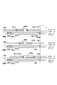
- the stacked state of the x stage 110, the y stage 120, and the stage base 130 will be described with reference to FIG.
- the x stage 110, the y stage 120, and the stage base 130 are stacked in the z direction.
- the y stage 120 is stacked on the stage base 130 so as to be movable in the y direction by the y axis cross roller guide 121a fixed to the lower surface of the y stage 120 and the y axis cross roller guide 121b fixed to the upper surface of the stage base 130. ing.
- the x stage 110 can move in the x direction on the y stage 120 by the x axis cross roller guide 111a fixed to the lower surface of the x stage 110 and the x axis cross roller guide 111b fixed to the upper surface of the y stage 120.
- FIG. 6 shows a state where the x stage 110 is moved in the x direction with respect to the y stage 120.
- the outer packaging member 201y of the linear actuator 200y is directly fixed to the lower surface of the y stage 120, and the frame 203y is fixed to the stage base 130 via an L-shaped bracket 181a.
- the linear actuator 200y is placed in a space in which the height direction of the stage base 130 and the y stage 120 is restricted. Can be arranged.
- FIG. 7A and 7B show a modification of the configuration for attaching the frame 203y to the stage base 130.
- FIG. 7A the frame 203y is fixed so that the bottom surface of the frame 203y and the surface of the stage base 130 are parallel to each other.
- the position in the height direction is adjusted by making the bracket 181a have a stepped shape as shown in the figure.
- FIG. 7B as in FIG.
- the frame 203y is fixed so that the bottom surface of the frame 203y and the surface of the stage base 130 are parallel to each other, but a flat plate is adopted as the bracket 181a.
- the concave portion is formed on the lower surface of the y stage 120 to absorb the size of the linear actuator 200y in the height direction.
- the x-axis cross roller guide 111b is arranged on the upper surface of the y stage 120, the x wire 173 is laid, the y axis cross roller guide 121a is arranged on the lower surface of the y stage 120, and the y wire 174 is laid.
- the configuration is shown. That is, a configuration for driving the x stage 110 is disposed on the upper surface of the y stage 120, and a configuration for driving the y stage 120 with respect to the stage base 130 is disposed on the lower surface.
- FIG. 8 is a diagram schematically showing the arrangement of components related to stage driving on the lower surface of the y stage 120 and the upper surface of the stage base 130. Since FIG. 8 is a schematic diagram for explaining the arrangement of the component parts, the size position and shape of the opening provided in the stage and the arrangement position and size of each component part are shown in FIG. It does not necessarily match the configuration diagram of the stage shown.
- the y-axis cross roller guide 121a and the outer member 201y of the linear actuator 200y are fixed to the lower surface of the y stage 120.
- a y wire 174 is hung between the y pulley 172 and the pulley 175a, the linear actuator 200y is disposed so that the y wire 174 and the shaft 202y are coaxial, and the y wire 174 is connected to the wire connecting portion 204y.
- an x-axis cross roller guide 111 b is fixed to the lower surface of the y stage 120.
- the outer packaging member 201x of the linear actuator 200x is fixed to the y stage 120 via a bracket (not shown).
- the x pulley 171 is arranged coaxially with the y pulley 172 so as to overlap in the vertical direction (Z direction), and an x wire 173 is hung between the x pulley 171 and the pulley 175b.
- the linear actuator 200x is disposed so that the x wire 173 and the shaft 202x are coaxial, and the x wire 173 is connected to the wire connecting portion 204x.
- the frame 203y holding the shaft 202y of the linear actuator 200y for driving the y stage 120 in the y direction is fixed to the stage base 130 via a bracket 181a, for example.
- a y-axis cross roller guide 121 b is disposed on the upper surface of the stage base 130.
- the y-axis cross roller guide 121a is configured to sandwich the y-axis cross roller guide 121b, and the y stage 120 is movable in the y direction with respect to the stage base 130. Accordingly, when the shaft 202y is driven in the y direction, the y stage 120 moves in the y direction with respect to the stage base 130.
- FIG. 9 is a view showing the upper surface of the y stage 120.
- the components for driving the stage are arranged on the lower surface of the y stage 120, and thus no components are arranged on the upper surface of the y stage 120. Therefore, the interval between the y stage 120 and the x stage 110 can be narrowed, and the size of the stage apparatus 100 in the height direction can be reduced.
- Two x-axis cross roller guides 111a are fixed to the x stage 110 via a bracket (not shown), and are fixed so as to sandwich the two x-axis cross roller guides 111b fixed to the y stage 120 from the outside. Thereby, the x stage 110 is stacked so as to be movable in the x direction with respect to the y stage 120. Since the x-axis cross roller guide 111a is fixed to the x stage 110 via a bracket, the y stage 120 is provided with an opening rod for passing the bracket along the x-axis cross roller guide 111b.
- FIG. 10 is a diagram showing a stacked state of the x stage 110, the y stage 120, and the stage base 130.
- FIG. The x-axis cross roller guide 111 does not exist between the x stage 110 and the y stage 120, and the thickness in the z direction of the stage apparatus 100 is reduced as compared with the structure shown in FIG. Further, in order to connect the x wire 173 laid on the lower surface of the y stage 120 and the shaft 202x of the linear actuator 200x coaxially, the position of the shaft 202x needs to be lower than the lower surface of the y stage 120. Therefore, the frame 203x is fixed to the x stage 110 via the bracket 181b.
- the x-axis cross roller guide 111a is fixed to the x stage 110 via a bracket 181d.
- the bracket 181d may be configured integrally with the mechanism of the x stage 110 in order to hold the cross roller guide firmly.
- the bracket 181c is a bracket for fixing the outer packaging member 201x of the linear actuator 200x in the x direction with respect to the y stage 120. With this, the position in the z direction of the outer packaging member 201x is adjusted to match the position of the shaft 202x.
- the stage base 130 supports the y stage 120 so as to be slidable in the y direction, and the y stage 120 supports the x stage 110 so as to be slidable in the x direction.
- the stage base 130 is fixed to the z base (not shown) of the mirror base of the microscope and does not move in the xy direction.
- the y-axis cross roller guide 121b disposed on the stage base 130 which does not move in the xy direction, the y-axis cross roller guide 121a disposed on the y stage 120, and the cross roller inserted therebetween are y Directional sliding mechanism.
- the sliding axis is an intermediate line in the y-axis direction of 121b and 121a, and two parallel intermediate lines in the y-axis direction are fulcrums (support lines) on which the stage base 130 supports the y stage 120.
- FIG. 11 is a diagram showing the configuration of the cross roller guide in the y stage 120 as the upper stage and the stage base 130 as the lower stage.
- 11 a and 11 b show a state in which the inner y-axis cross roller guide 121 b is disposed on the y stage 120 and the outer y-axis cross roller guide 121 a is disposed on the stage base 130.
- 11c and 11d show a state where the outer y-axis cross roller guide 121a is disposed on the y stage 120, and the inner y-axis cross roller guide 121b is disposed on the stage base 130.
- the y-axis cross roller guide 121b fixed to the stage base 130, which is the lower stage, is on the inside, and the recess (V groove) for inserting the cross roller faces the outside.
- the y-axis cross roller guide 121a fixed to the y stage 120, which is the upper stage, is on the outside, and is fixed so that the concave portion (V groove) for inserting the cross roller faces the inner direction.
- the x-axis cross roller guide 111 between the x stage 110 and the y stage 120. That is, the x-axis cross roller guide 111a fixed to the x stage 110 as the upper stage is on the outside, and the x-axis cross roller guide 111b fixed to the y stage 120 as the lower stage is on the inside.
- FIGS. 12A to 12D, FIGS. 13A to 13D, and FIGS. 14A to 14B a procedure for assembling the cross roller guide in the stage apparatus 100 described with reference to FIGS. 8 to 10 will be described.
- the x-axis cross roller guide 111 and the y-axis cross roller guide 121 are arranged on the same surface (the lower surface in FIGS. 8 to 10) of the y stage 120, the assembly of the cross roller guide is easy. become.
- the pair of inner y-axis cross roller guides 121b is fixed to the upper surface of the stage base 130 so as to press the rectangular y-axis (for inner side) parallel jig 301 from the outer side.
- the pair of inner x-axis cross roller guides 111b is fixed to the lower surface of the y stage 120 so as to press the rectangular x-axis (for inner) parallel jig 302 from the outer side.
- one of the two outer y-axis cross roller guides 121 a is fixed to the lower surface of the y stage 120 using a right angle jig 303.
- the outer y-axis cross roller guide 121a With one side of the right-angle jig 303 pressed against one of the inner x-axis cross roller guides 111b fixed in FIG. 12B, the outer y-axis cross roller guide 121a is pushed against the other side of the right-angle jig 303. Fix it by hitting.
- the outer y-axis cross roller guide 121a is fixed perpendicularly to the inner x-axis cross roller guide 111b.
- the pair of y-axis cross roller guides 121 a outside the y stage 120 is connected to the inside of the stage base 130.
- the y stage 120 is placed on the stage base 130 so as to sandwich the pair of y-axis cross roller guides 121b from the outside.
- the cross roller is inserted into the V groove between the outer y-axis cross roller guide 121a and the inner y-axis cross roller guide 121b.
- the temporarily fixed outer y-axis cross roller guide 121a is pushed inward with a predetermined torque, and the temporarily fixed y-axis cross roller guide 121a is in that state. Is fixed to the y stage 120.
- the bank 304a is not shown in FIGS. 8 to 10, etc., it is necessary to push the outer y-axis cross roller guide 121a provided on the y stage 120 in the assembly adjustment of the cross roller guide.
- the configuration is provided on the lower surface of the y stage 120.
- the bank 304 a may be provided as a configuration (jig) that can be detached from the y stage 120.
- the adjustment screw 305a is preferably provided according to a screw (not shown) position for fixing the y-axis cross roller guide 121a to the y stage 120.
- the outer y-axis cross roller guide 121a fixed to the y stage 120 is disposed so as to sandwich the inner y-axis cross roller guide 121b on the stage base 130. Therefore, the inner y-axis cross roller guide 121b and the outer y-axis cross roller guide 121a are pressed with an appropriate force by pressing the temporarily fixed outer y-axis cross roller guide 121a with the adjusting screw 305a with a predetermined torque. It will be in a proper condition.
- FIG. 13A This state is shown in FIG. 13A. In this state, the assembly of the y-axis cross roller guide is completed by firmly fixing the y-axis cross roller guide 121a to the y stage 120.
- the bank 304a functions as a cross roller guide pressing adjustment mechanism. That is, the bank 304a applies a force that pushes one of the outer cross roller guides in which the concave portion for inserting the cross roller faces the inner direction toward the inner direction of the stage.
- the cross roller guide can be fixed by setting the outer cross roller guide to a predetermined pressing state with respect to the inner cross roller guide in which the concave portion for inserting the cross roller faces outward.
- the outer x-axis cross roller guide 111a is fixed so as to sandwich the x-axis (outer) parallel jig 306, and then one of the adjustment axes is adjusted.
- the outer x-axis cross roller guide 111a is loosened, shifted outward, and temporarily fixed.
- the x stage 110 is stacked on the y stage 120.
- the outer x-axis cross roller guide 111 a fixed to the x stage 110 is disposed so as to sandwich the inner x-axis cross roller guide 111 b on the y stage 120.
- the cross roller is inserted into a V groove between the outer x-axis cross roller guide 111a and the inner x-axis cross roller guide 111b.
- the temporarily fixed outer x-axis cross roller guide 111a is pushed inward with a predetermined torque (FIG. 13C).
- the stopped x-axis cross roller guide 111 a is fixed to the x stage 110.
- the inner x-axis cross roller guide 111b and the outer x-axis cross roller guide 111a are pressed with an appropriate force (FIG. 13D).
- FIGS. 8 to 10 and the like it is necessary to push the outer x-axis cross roller guide 111a provided on the x stage 110 in the assembly adjustment of the cross roller guide.
- the configuration is provided on the lower surface of the x stage 110.
- the bank 304b may be provided as a detachable configuration (jig) with respect to the x stage 110.
- the adjustment screw 305b is preferably provided in accordance with a screw (not shown) position for fixing the x-axis cross roller guide 111a to the y stage 120.
- the outer x-axis cross roller guide 111a fixed to the x stage 110 is disposed so as to sandwich the inner x-axis cross roller guide 111b on the y stage 120. In this state, the assembly of the x-axis cross roller guide 111 is completed by firmly fixing the outer x-axis cross roller guide 111a to the x stage 110.
- FIG. 14A shows a layout of the x wire 173 and the y wire 174. 14A shows the arrangement state of the components without distinction between the upper and lower surfaces of the y stage 120.
- FIG. 170 regarding the movement of the x stage 110 in the x direction, the x roller 177 connected to the shaft of the x knob 161 (FIG. 1) rotates in accordance with the rotation operation of the x knob 161.
- the x transmission roller 179x presses the x roller 177 and the x pulley 171 during manual driving, and transmits the rotation of the x roller 177 to the x pulley 171.
- manual driving and electric driving are switched by switching between pressing and releasing the x roller 177 and the x pulley 171 by the x transmission roller 179x.
- the y roller 178 connected to the shaft of the y knob 162 (FIG. 1) rotates in accordance with the rotation operation of the y knob 162.
- the y transmission roller 179y presses the y roller 178 and the y pulley 172 during manual driving, and transmits the rotation of the y roller 178 to the y pulley 172.
- FIG. 14B is a diagram showing another example of laying the y wire 174. According to the layout of FIG. 14B, the arrangement positions of the manual drive mechanism 170 and the linear actuators 200x and 200y are distributed, so that the stage balance is improved. However, the routing distance of the x wire 173 becomes longer.
- the shaft 202 that is the driven part at the time of the electric drive and the drive wire that is the driven part at the time of the manual drive are parallel to the moving direction of the stage.
- the operation axis is common.
- a shaft motor a linear motor using a shaft, or a cylindrical linear motor if the shaft is a cylinder
- backlash is unlikely to occur.
- the position of the xy stage is kept stable. Therefore, for example, if the stage apparatus 100 is used as a microscope stage, the observation position does not shift in switching between electric drive and manual drive, and the user can perform microscope observation without feeling stress.
- a shaft motor (cylindrical linear motor) is used as the main configuration of the linear actuator.
- a shaft motor includes an outer packet member that is a separate member whose positional relationship is not mechanically fixed, and a shaft (cylindrical rod member) that is inserted into the outer packet member.
- the shaft and the outer packaging member are separate members whose positional relationship is not fixed until they are attached, it is necessary to manage them appropriately so as not to cause damage to the rod member, bending, or magnetic attachment such as metal pieces before assembly. This also leads to cost increase.
- a form of providing a linear actuator suitable for application to the stage apparatus described above is disclosed. According to the linear actuator of the second embodiment, the assembly and adjustment of the stage apparatus described in the first embodiment can be simplified, and the manufacturing cost can be reduced.
- the linear actuator 200 exemplified in the second embodiment is not limited to application to a microscope stage, but can be provided as various one-dimensional stage and two-dimensional stage linear actuators.
- the linear actuator 200 of this embodiment is A linear motor in a form in which the shaft 202 is inserted into the through hole of the outer packet member 201 and the outer packet member 201 (one of the outer packet member 201 and the shaft 202 has a coil, and the other has a permanent magnet), A connecting portion for connecting the manual operation wire and the shaft 202 coaxially; A frame 203 for attaching the shaft 202;
- the shaft 202 is an integrated linear actuator that is provided in a state where the shaft 202 is inserted through the outer packaging member 201 and the shaft 202 is assembled with a predetermined accuracy with respect to the position reference of the frame 203.
- the linear actuator 200 shown in FIG. 3A shows an example in which a linear actuator that can obtain the predetermined accuracy is configured as a result of mounting.
- a configuration example of the linear actuator 200 of the present embodiment will be described.
- the linear actuator 200a shown in FIGS. 15A to 15D is obtained by modifying the wire connecting portion 204 of the linear actuator 200 described with reference to FIGS. 3A to 3D.
- the wire connecting portion is attached to the shaft 202 with the frame 203 interposed during mounting, and the position (phase) in the rotation direction of the wire fixing screw 205 can be arbitrarily determined depending on mounting convenience. Can be in position.
- the wire fixing portion (connection cover 222 and wire fixing screw 205) is configured to be rotatable to the shaft fixing portion (shaft fixing screw 221). Yes.
- the position of the wire fixing screw 205 can be rotated to fix the wire at a suitable position.
- the wire connecting portion 204 provides a wire connecting mechanism that can attach a drive wire so as to be coaxial with the shaft axis on both ends of the shaft. It is a configuration.
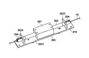
- FIG. 15A is a diagram showing an appearance of the linear actuator 200a.
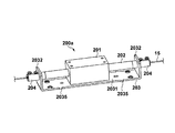
- the frame 203 has a U-shape, has a bottom panel 2031 and side panels 2032 on both sides thereof, and both ends of the shaft 202 are fixed to the side panel 2032 with a predetermined accuracy.
- the wire connecting portion 204 is screwed at both ends of the shaft 202 through a through hole with a predetermined accuracy formed in the two side panels 2032 (not large unlike the case shown in FIGS. 3A to 3D).
- a screw portion (shaft fixing screw 221 in FIG. 15B) to be fixed between 2032 is provided.
- the wire connection part 204 has a wire fixing part (connection cover 222 of FIG. 15B) which fixes the end part of a drive wire (x wire 173, y wire 174) so that it may become coaxial with the thread part. This will be specifically described below.
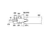
- the wire connecting portion 204 of the linear actuator 200a has a shaft fixing screw 221, a connecting cover 222, and a connecting cover fixing screw 223 as shown in FIG. 15B.
- the shaft fixing screw 221 fixes the shaft 202 to the side panel 2032 of the frame 203 by screwing with the screw portion 213 provided at the end portion of the shaft 202.
- a cylindrical portion 2211 that fits into the through hole of the side panel 2032 is provided adjacent to the screw portion of the shaft fixing screw 221, and the position of the shaft 202 and the shaft fixing screw 221 is coaxial with a predetermined accuracy. It is trying to become.
- connection cover 222 has a recess that encloses the shaft fixing screw 221, and has a hole for inserting the drive wire 15 on the opposite surface of the recess.
- the connection cover 222 is fixed to the shaft fixing screw 221 by a connection cover fixing screw 223. Further, the end portion of the drive wire 15 inserted into the connection cover 222 is fixed to the connection cover 222 by a wire fixing screw 205. Note that a sleeve having a predetermined diameter is attached to the tip of the drive wire 15 so that the axes of the drive wire 15 and the shaft 202 are more accurately aligned.
- the drive wire 15 is connected to the shaft 202 in a coaxial relationship.
- the connection cover 222 can be conveniently fixed to the shaft fixing screw 221 at an arbitrary rotational position where the access to the wire fixing screw 205 is easy by the connection cover fixing screw 223.
- the fixing of the drive wire 15 to the hole 212 is not limited to the illustrated form, and any structure may be used.
- the end of the drive wire 15 may be fixed to the hole 212 by caulking.
- the end of the drive wire is inserted into a hole of a cylindrical pin 1501 having a cylindrical hole and fixed by a screw or caulking, and the other end of the cylindrical pin to which the drive wire 15 is connected to one end. May be inserted into the hole 212 and fixed with the wire fixing screw 205.
- FIG. 15D shows the linear actuator 200a shown in FIG. 15A in which the frame 203 has a bottom panel 2031 extending further outward than the side panel 2032.
- the wire connection portion 204 extends from the side panel 2032, and the position where the wire of the wire connection portion 204 is connected is on the extension of the axis of the shaft 202.
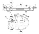
- FIG. 20 is a diagram for explaining the position reference in the linear actuator 200a.
- the frame 203 has a reference convex portion 2035 and a reference convex portion as an axial position reference and an axial reference having a predetermined positional relationship with respect to the axial position and the axial direction defined by the through holes provided in the two side panels 2032. 2036.
- the axial position is the position of the central axis of the shaft 202 fixed to the frame 203
- the axial direction is the direction of the central axis.
- the reference convex portion 2035 defines a distance A from the apex position of the reference convex portion 2035 to the center position (coaxial position) of the shaft 202, as shown in FIG.
- a distance B to the center position of the shaft 202 is defined by the reference convex portion 2036 around the attachment hole.
- the axial position of the shaft 202 is defined by the reference convex portions 2035 and 2036.
- a line connecting the apexes of the reference convex portion 2035 on the same side of the bottom panel indicates the axial direction of the shaft 202 (parallel to the axial direction of the shaft 202).
- the linear actuator 200a can be accurately and easily incorporated into the stage apparatus 100 of the first embodiment.
- the frame 203 has the same position reference and axial reference.
- FIGS. 16A and 16B are diagrams showing a linear actuator 200b which is still another configuration example of the linear actuator 200.
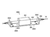
- FIG. FIG. 16A is a diagram illustrating an appearance of the linear actuator 200b.
- FIG. 16B is an exploded view of the linear actuator 200b.
- the shaft 202 is inserted into the through hole of the outer packet member 201, and both ends of the shaft 202 are fixed to the frame 203 by the wire connecting portion 204 with a predetermined accuracy.
- a screw portion that fits the screw portion 213 of the shaft 202 is formed at one end portion, and a hook portion 231 is formed at the other end portion.
- Both ends of the shaft 202 are screwed through the through holes with predetermined accuracy formed in the two side panels 2032 by the screw portions, and the shaft 202 is fixed between the two side panels 2032 with predetermined accuracy.
- the hook portion 231 serving as an end portion of the wire connection mechanism has a hook shape for catching the drive wire 15 having an end portion formed in a ring shape.
- FIG. 17A to 17B are diagrams showing a linear actuator 200c which is still another configuration example of the linear actuator 200.
- FIG. 17A is a perspective view showing an appearance of the linear actuator 200c
- FIG. 17B is a cross-sectional view of the linear actuator 200c
- 17c is a detailed cross-sectional view of the shaft fixing portion and the wire connecting portion.
- the frame 203 of the linear actuator 200c includes a pair of side panels 2032 that are orthogonally opposed to the bottom panel 2031 and a second side panel that is disposed to sandwich the pair of side panels 2032 and is orthogonal to the bottom panel 2031. 2033 pairs.
- both ends of the shaft 202 are fixed to the side panel 2032 of the frame 203 by the shaft fixing screws 221a.
- the bottom panel 2031 of the frame 203 extends further outward than the position of the side panel 2032, and second side panels 2033 are provided at both ends of the bottom panel 2031.
- the driving wire 15 is connected to the second side panel 2033 by a wire connecting portion 204a.
- the shaft 202 has screw portions 213 at both ends, and is screwed with the side panel 2032 interposed between the shaft fixing screws 221a and fixed to the side panel 2032.
- a screw portion is provided at one end of the wire connection portion 204 a, and the second side panel 2033 is clamped by a fixing screw 232 to be fixed to the second side panel 2033.
- the holes in the side panel 2032 and the second side panel 2033 are formed so that the shaft 202 and the wire are arranged coaxially.
- the second side panel 2033 for fixing the wire connection portion 204a is provided on the bottom panel 2031 extending further outward from the position of the side panel 2032.
- the present invention is not limited to this. It is not something that can be done. Since the shaft 202 and the drive wire 15 need only be fixed so that the shaft 202 and the drive wire 15 are coaxial, various modifications are possible. For example, a configuration may be adopted in which a member extending in the axial direction of the shaft 202 from either one of the two sides and the upper side of the side panel 2032 and the second side panel 2033 are provided at the end thereof.
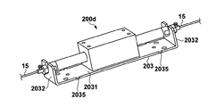
- FIG. 18A to 18C are diagrams showing a linear actuator 200d as still another modified example of the linear actuator 200.
- FIG. 18A is a perspective view showing the appearance of the linear actuator 200d
- FIG. 18B is an exploded view of the linear actuator 200d
- FIG. 18C is a view showing a modification of the frame 203.
- FIG. In the linear actuator 200d in the shaft motor in which the shaft 202 is inserted into the through hole of the outer packet member 201, the shaft 202 has a wire connecting portion 204c at both ends thereof.
- the shaft 202 is fixed to the side panel 2032 of the frame 203 by the screw portion 213a of the wire connection portion 204c and the shaft fixing nut 233.
- the side panel 2032 has a U-shaped notch formed with a predetermined accuracy to receive the shaft 202 having the wire connection portion 204c. That is, by firmly inserting the shaft 202 into the U-shaped notch, the positional relationship between the shaft position of the shaft 202 and the frame 203 is maintained at the same level as shown in FIG.
- a hole 212 for receiving a wire is provided on the end surface of the wire connection portion 204c on the tip side of the screw portion 213a.
- the drive wire 15 is fixed to the wire connecting portion 204c by inserting the drive wire 15 into the hole portion 212 and tightening it in the radial direction with the wire fixing screw 205.
- a separate frame 203a as shown in FIG. 18C may be used as the frame 203 for fixing the shaft 202 integrated with the wire connection portion to the stage as described above.
- the separated frame 203a has an L shape including a bottom panel 2031a and a side panel 2032a.
- the positional relationship between the separated frame 203a and the shaft 202 needs to be maintained with a predetermined accuracy.
- Such a separation type frame can also be applied to the linear actuator shown in FIGS. 15A to 15D, FIGS. 16A to 16B, FIGS. 17A to 17B, and FIGS. 18A to 18C. Even when the shaft motor shown in FIGS. 3A to 3D is used, the separation type frame is convenient for mounting, and the separated frame 203a may be formed on the stage side.
- FIG. 19A to 19D are diagrams showing a linear actuator 200e as still another modification of the linear actuator 200.
- the wire connection mechanism of the linear actuator 200e includes a configuration for moving the fixed position of the drive wire in the axial direction of the shaft 202, and thereby the tension of the drive wire 15 can be adjusted.
- the tension of the drive wire is adjusted by, for example, moving the pulley 175a in the y direction or moving the pulley 175b in the x direction in FIG. 14A.
- the tension of the drive wire can be adjusted in the frame 203 by the following configuration. Therefore, the user can adjust the tension more easily.
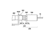
- the linear actuator 200e has a tension adjusting unit 240 that fixes the shaft 202 to the side panel 2032, connects the x wire 173 or the y wire 174, and enables adjustment of the tension of the connected wire.
- 19A is an external view of the linear actuator 200e
- FIG. 19B is an exploded configuration diagram of the shaft fixing portion and the tension adjusting portion 240
- FIG. 19C is an assembled state diagram of the tension adjusting portion
- FIG. 19D is a cross-sectional configuration diagram of the tension adjusting portion 240. Indicates.
- the shaft 202 is screwed to the side panel 2032 by a screw portion 213 and a shaft fixing screw 221 provided on an end surface thereof, and is fixed with a predetermined accuracy.
- the tension adjustment unit 240 includes an adjustment screw part 241, an adjustment sleeve fixing nut 242, a wire fixing part 243, and a tension adjustment sleeve 244.
- the adjustment screw portion 241 includes a cylindrical portion 2411 a having a recess that accommodates the shaft fixing screw 221, and a screw portion 2411 b that matches screws formed on the adjustment sleeve fixing nut 242 and the tension adjustment sleeve 244.
- the cylindrical portion 2411a is provided with a screw hole 2411c for the fixing screw 223.
- the shaft 202 is fixed to the frame 203 (side panel 2032) with a predetermined accuracy by the shaft fixing screw 221. Thereafter, the shaft fixing screw 221 is covered with the recess of the adjusting screw portion 241, and the adjusting screw portion 241 is fixed to the shaft fixing screw 221 with the fixing screw 223 in the accommodated state.
- the wire fixing portion 243 has a hole for inserting the driving wire 15, and the driving wire 15 inserted into the hole through the through hole of the tension adjusting sleeve 244 is fixed by the wire fixing screw 205.
- the wire fixing portion 243 is accommodated in the tension adjustment sleeve 244.
- the tension adjusting sleeve 244 (having a screw portion on the inside) is turned and screwed into the screw portion of the adjusting screw portion 241, and the position of the wire adjusting portion 243 is changed in the axial direction by changing the position of the tension adjusting sleeve 244 (
- the tension of the drive wire 15 can be adjusted by moving in the direction of the arrow 1901. That is, the distance between the wire fixing portions 243 on both sides of the linear actuator 200e changes due to the change in the position of the tension adjusting sleeve 244.
- the tension adjustment sleeve 244 is tightened by the adjustment sleeve fixing nut 242 and the position in the adjustment screw portion 241 is fixed. In this way, the tension of the drive wire 15 can be adjusted.
- the grace and tension adjustment mechanism has been described as being provided at both ends of the shaft of the linear actuator, but may be provided only on one side.
- the tension adjusting unit 240 described above has a hook-shaped wire connecting portion as shown in FIG. 16A, a wire connecting portion provided on another side panel as shown in FIG. 17A, and a shaft connecting portion as shown in FIG. 18A.
- the present invention can be applied to any form such as a case where wire connection portions are provided at both ends.
Landscapes
- Physics & Mathematics (AREA)
- Engineering & Computer Science (AREA)
- Chemical & Material Sciences (AREA)
- Power Engineering (AREA)
- Analytical Chemistry (AREA)
- General Physics & Mathematics (AREA)
- Optics & Photonics (AREA)
- Combustion & Propulsion (AREA)
- Electromagnetism (AREA)
- Details Of Measuring And Other Instruments (AREA)
- Microscoopes, Condenser (AREA)
Abstract
自動モードと手動モードの間の切換え時におけるステージ位置(観察位置)の微妙な移動の発生を低減するステージ装置を提供する。ステージ装置は、第1のステージと、第1のステージの面上を第1の方向に相対的に移動する第2のステージと、手動による駆動力により、第2のステージを第1の方向へ相対的に移動させるための第1の被駆動部を駆動する第1の駆動部と、電動による駆動力により、第2のステージを第1の方向へ相対的に移動させるための第2の被駆動部を駆動する第2の駆動部とを有する。ここで、第1の被駆動部と第2の被駆動部の少なくとも一部が共通の動作軸を有する。
Description
本発明は、ステージ装置および該ステージ装置の駆動に用いられるリニアアクチュエータに関する。
顕微鏡に利用されるステージ装置(以下、顕微鏡ステージ)は、観察対象のスライドガラスを載置して、所望の観察領域が顕微鏡視野へ入るように対物レンズに対してxおよびy方向へ移動する。特に病理診断に用いられる顕微鏡では、細胞レベルの観察が要求されるため、顕微鏡ステージに対して高い位置管理精度が要求されている。また、スライドガラスをxおよびy方向へ移動するための操作手段としては、高精度で精細な操作性および応答性が重視されため、xおよびy方向の摘みを手動操作で回す手動操作機構が使われている。
特許文献1では、顕微鏡ステージとして利用可能な、円筒型リニアモータを用いた電動式ステージが記載されている。この円筒型リニアモータは、原理的にバックラッシュが発生しにくいため、ステージ装置において観察位置を高精度で自動制御することが可能となる。
一般に、病理診断では、手動モードで顕微鏡ステージを移動して観察を行う。手動モードでは、観察位置を高精度で精細な操作性および応答性で移動できることが要求される。また、顕微鏡ステージでは、上記のような手動モードに加え、電動によりステージを移動する自動モードを実現できることが求められている。自動モードでは、例えば、手動モードにおいて観察した関心領域(Region of Interest)の位置を例えばxy座標で記憶しておき、その記憶された位置へ、速やかに高精度で、自動的に戻ることが出来る。
特許文献1に記載された電動式ステージは、自動モードによるステージの駆動を実現できる。また、ジョイスティクや摘みなどの手動操作部材から得られる電気信号に基づいて電動式ステージを駆動することで、擬似的な手動モードを実現することができる。しかしながら、そのような擬似的な手動モードでは、使用者の微細な操作が高精度且つ高速に反映されず、使用者はストレスを感じてしまう。したがって、手動モードに関しては、機械的な構造により使用者の操作をステージの移動へ変換する構成を用いることが望ましい。このような自動モードと手動モードを実現するステージ装置を実現しようとした場合、特許文献1の電動式ステージのような自動モードの機構と、手動モードのための機構と、それらを切り替える機構を設けることが考えられる。そして、手動モードから自動モード、自動モードから手動モードへの切り替わりの際には、観察位置の微小な移動が生じたりしないようなステージ機構が求められている。顕微鏡観察時では、そのような微動が観察像において大きく現われ、使用者がストレスを感じることになるからである。
本発明の一実施形態では、自動モードと手動モードの間の切換え時におけるステージ位置(観察位置)の微妙な移動の発生を低減するステージ装置が提供される。
本発明の一態様によるステージ装置は以下の構成を備える。すなわち、
第1のステージと、
前記第1のステージの面上を第1の方向に相対的に移動する第2のステージと、
手動による駆動力により、前記第2のステージを前記第1の方向へ相対的に移動させるための第1の被駆動部を駆動する第1の駆動手段と、
電動による駆動力により、前記第2のステージを前記第1の方向へ相対的に移動させるための第2の被駆動部を駆動する第2の駆動手段と、を備え、
前記第1の被駆動部と前記第2の被駆動部の少なくとも一部が共通の動作軸を有する。
第1のステージと、
前記第1のステージの面上を第1の方向に相対的に移動する第2のステージと、
手動による駆動力により、前記第2のステージを前記第1の方向へ相対的に移動させるための第1の被駆動部を駆動する第1の駆動手段と、
電動による駆動力により、前記第2のステージを前記第1の方向へ相対的に移動させるための第2の被駆動部を駆動する第2の駆動手段と、を備え、
前記第1の被駆動部と前記第2の被駆動部の少なくとも一部が共通の動作軸を有する。
本発明によれば、自動モードと手動モードの間の切換え時におけるステージ位置(観察位置)の微妙な移動の発生が低減される。
本発明のその他の特徴及び利点は、添付図面を参照とした以下の説明により明らかになるであろう。
添付図面は明細書に含まれ、その一部を構成し、本発明の実施の形態を示し、その記述と共に本発明の原理を説明するために用いられる。
実施形態によるステージ装置100の外観の一例を示す模式図。
ステージ装置100を構成するxステージ、yステージ、ステージベースの外観の一例を示す図。
、
、
、
リニアアクチュエータの構造の一例を説明する図。
yステージ下面とステージベース上面における構成部品の配置の一例を示す図。
yステージ上面とxステージ上面における構成部品の配置の一例を示す図。
xステージ、yステージ、ステージベースの積層状態の一例を説明する図。
、
リニアアクチュエータのフレームの取り付けに関する変形例を示す図。
変形例による、yステージへの構成部品の配置の一例を示す図。
変形例による、yステージへの構成部品の配置の一例を示す図。
xステージ、yステージ、ステージベースの積層状態の一例を説明する図。
内側クロスローラガイドと外側クロスローラガイドの配置の一例を説明する図。
、
、
、
クロスローラガイドの組み立て手順(ステージの積層手順)の一例を説明する図。
、
、
、
クロスローラガイドの組み立て手順(ステージの積層手順)の一例を説明する図。
、
リニアアクチュエータの配置の一例を説明する図。
、
、
、
実施形態によるリニアアクチュエータの構造の一例を説明する図。
、
実施形態によるリニアアクチュエータの構造の一例を説明する図。
、
実施形態によるリニアアクチュエータの構造の一例を説明する図。
、
、
実施形態によるリニアアクチュエータの構造の一例を説明する図。
、
、
、
実施形態によるリニアアクチュエータの構造の一例を説明する図。
リニアアクチュエータにおける位置基準の一例を説明する図。
以下、添付の図面を参照して本発明の好適な実施形態のいくつかを説明する。
<第1実施形態>
図1は、第1実施形態によるステージ装置100の外観を示す模式図である。本実施形態では、ステージ装置100を、観察対象のスライドを載置して、顕微鏡の鏡基に対してx方向およびy方向へ移動する顕微鏡用ステージとして用いる例を説明する。ステージ装置100は、ステージベース130、yステージ120、xステージ110が積層された構造を有するxyステージである。なお、積層順序は図1の例に限定されるものではなく、xステージ110の上部にyステージ120を設ける構成としてもよい。ステージ装置100において、yステージ120はステージベース130の面上をy方向に相対的に移動する。また、xステージ110はyステージ120の面上をx方向に相対的に移動する。ここで、ステージベース130は第1のステージの一例に相当し、yステージ120は第2のステージの一例に相当する。また、xステージ110は第3のステージの一例に相当する。また、y方向は第1の方向の一例に相当し、x方向は第2の方向の一例に相当する。なお、yステージ120を第1のステージの一例、xステージ110を第2のステージの一例として捉えることとしても良く、この場合にはx方向は第1の方向の一例となる。
図1は、第1実施形態によるステージ装置100の外観を示す模式図である。本実施形態では、ステージ装置100を、観察対象のスライドを載置して、顕微鏡の鏡基に対してx方向およびy方向へ移動する顕微鏡用ステージとして用いる例を説明する。ステージ装置100は、ステージベース130、yステージ120、xステージ110が積層された構造を有するxyステージである。なお、積層順序は図1の例に限定されるものではなく、xステージ110の上部にyステージ120を設ける構成としてもよい。ステージ装置100において、yステージ120はステージベース130の面上をy方向に相対的に移動する。また、xステージ110はyステージ120の面上をx方向に相対的に移動する。ここで、ステージベース130は第1のステージの一例に相当し、yステージ120は第2のステージの一例に相当する。また、xステージ110は第3のステージの一例に相当する。また、y方向は第1の方向の一例に相当し、x方向は第2の方向の一例に相当する。なお、yステージ120を第1のステージの一例、xステージ110を第2のステージの一例として捉えることとしても良く、この場合にはx方向は第1の方向の一例となる。
より具体的には、ステージベース130は、顕微鏡の鏡基のzベース(不図示)に固定される。yステージ120はステージベース130上を、y軸クロスローラガイド121に沿ってy方向へ移動可能であり、xステージ110はyステージ120上を、x軸クロスローラガイド111に沿ってx方向へ移動可能である。この結果、xステージ110上に形成される位置管理面ステージ101を、ステージベース130に対して(顕微鏡の鏡基に対して)x方向およびy方向の2方向へ移動させることが可能なxyステージが提供される。位置管理面ステージ101は、位置管理面ステージ101の位置管理を行うためのxyスケール板102や、スライドが載置されるスライド載置ステージ103を有する。なお、xyステージはスライドを載置して対物レンズに対してxy方向へ移動可能であればよく、xy位置を管理するための構成(位置管理面ステージ101など)は図1のものに限られない。ユーザは、手動摘み160のx摘み161を回すことによりxステージ110をx方向へ移動させることができ、y摘み162を回すことによりyステージ120をy方向へ移動させることができる。よって、ユーザは手動摘み160を操作することにより位置管理面ステージ101をxy方向に移動させることができる。y摘み162は第1の駆動手段の一例に相当する。また、x摘み161は第3の駆動手段の一例に相当する。
図2は、ステージ装置100を構成するxステージ110、yステージ120、ステージベース130のそれぞれの外観を示す図である。
xステージ110には、yステージ120に配置されるx軸クロスローラガイド111bと対になるx軸クロスローラガイド111aが配置されている。ステージベース130には、yステージ120に配置されるy軸クロスローラガイド121aと対になるy軸クロスローラガイド121bが配置されている。2つのx軸クロスローラガイド111aは2つのx軸クロスローラガイド111bを外側から挟むように配置されており、2つのy軸クロスローラガイド121aは2つのy軸クロスローラガイド121bを外側から挟むように配置されている。x軸クロスローラガイド111a、111bを、それらの間にクロスローラを挿入した状態で固定することにより、xステージ110はyステージ120の面上をx軸方向に移動可能となる。同様に、y軸クロスローラガイド121a、121bの間にクロスローラを挿入して固定することで、yステージ120はステージベース130の面上をy軸方向に移動可能となる。
yステージ120には、xステージ110をyステージに対してx方向へ移動させるための駆動機構と、yステージ120をステージベース130に対してy方向へ移動させるための駆動機構が搭載されている。手動駆動機構170は、手動による駆動力により、xステージ110をyステージ120に対してx方向へ移動させるための被駆動部(本実施形態ではxステージに連結されたワイヤ)を駆動する。同様に、手動駆動機構170は、yステージ120をステージベース130に対してy方向へ移動させるための被駆動部(本実施形態ではステージベース130に連結されたワイヤ)を駆動する。より具体的には、x摘み161、y摘み162の回転動作を、それぞれ、図4以降でより具体的に示すxワイヤ173、yワイヤ174の移動動作に変換する。xワイヤ173の移動によりxステージ110がyステージ120に対してx方向へ移動し、yワイヤ174の移動によりyステージ120がステージベース130に対してy方向へ移動する。yワイヤ174は第1の被駆動部の一例に相当する。また、xワイヤ173は第3の被駆動部の一例に相当する。
x方向用のリニアアクチュエータ200xは、xステージ110をyステージ120に対してx方向へ移動させるための駆動力を提供するリニアアクチュエータである。y方向用のリニアアクチュエータ200yはyステージ120をステージベース130に対してy方向へ移動させるための駆動力を提供するリニアアクチュエータである。リニアアクチュエータ200x、200yは同様の構造を有しているので、以下これらを総称する場合には、リニアアクチュエータ200と記載する。また、リニアアクチュエータ200がx方向用かy方向用かを区別する際には、参照符号の末尾にx、yを付す。
図3A~図3Dは、本実施形態によるリニアアクチュエータ200の構造を説明する図である。図3Aは、リニアアクチュエータ200の上面、正面、下面、側面を示す図である。図3B、図3Dは、リニアアクチュエータ200を、構成要素で分解して示した斜視図である。図3Cの3cはリニアアクチュエータ200の取り付けを説明する図である。図3Cの3dは、3cの一部の断面を示す図である。本実施形態のリニアアクチュエータ200は、外包部材201と外包部材201を貫通する穴に挿通されるシャフト202よりなる所謂シャフトモータ(シャフトを用いるリニアモータ)を用いている。すなわち、該シャフトモータの該外包部材201の貫通孔211に該シャフト202を通した状態で、シャフト202をフレーム203に設けた大きめの穴214にワイヤ接続部204を用いて固定している。そして、ステージ装置100の実装に際し、駆動ワイヤ15(図4以降でより具体的に示すxワイヤ173、yワイヤ174)とシャフト202の軸が同軸になる様に、シャフト202がフレーム203にワイヤ接続部204でもって固定される。
以上のような実装の結果として、図3A、図3Bに示されるようなリニアアクチュエータ200が構成される。図示のようにリニアアクチュエータ200は、外包部材201と、外包部材201の貫通孔211を摺動可能に挿通されたシャフト202と、シャフト202をフレーム203に固定するとともに駆動ワイヤを接続するためのワイヤ接続機構を提供するワイヤ接続部204と、を具備する。外包部材201とシャフト202の一方がコイルを有し、他方が磁石を有しており、コイルを有する部材への通電により磁石を含む部材がコイルに対して相対的に移動する。すなわち、電動による駆動力を提供する本実施形態によるリニアアクチュエータ200は、外包部材201と外包部材201を貫通する穴に挿通されるシャフト202よりなる所謂シャフトモータ(シャフトを用いるリニアモータ)が実装時にフレーム203に固定されたものである。リニアアクチュエータ200では、電気信号の付与に応じてシャフト202がその長手方向(軸方向)へ動作する。
シャフト202は、円形状の断面を有し、外包部材201の貫通孔211に挿通された状態で、実装時にフレーム203に組み込まれ、その両端部がワイヤ接続部204によりフレーム203に固定される。図3Cに示されるように、ワイヤ接続部204の一端にはシャフト202の端部に設けられたネジ部213に対応したネジ部が設けられており、他端にはワイヤ固定用の穴部212が設けられている。穴部212に駆動ワイヤ(後述のxワイヤ173またはyワイヤ174)を差し込み、ワイヤ固定ネジ205で径方向から締め付けることにより、シャフト202と実質的に同軸に駆動ワイヤが接続されることになる。ここで、同軸というのは、駆動ワイヤの中心軸とシャフト202の中心軸が一致した状態のことである。なお、図3A~図3Cでは、駆動ワイヤをワイヤ固定ネジ205で穴部212に固定する形態を示したが、駆動ワイヤを固定する方法はこれに限られるものではない。シャフト202と駆動ワイヤが同軸となるように固定できればいかなる構造を採用してもよく、たとえば、カシメにより駆動ワイヤを穴部212に固定するようにしてもよい。または、一端に円筒穴を有する円筒ピンの円筒穴に駆動ワイヤの端部を差し込み、ネジまたはカシメにより円筒ピンを駆動ワイヤの端部に固定しておき、この円筒ピンの他端を穴部212に挿入し、ワイヤ固定ネジ205で固定するようにしても良い。
また、外包部材201は、外包部材固定ネジ206によりyステージ120に直接に、または取り付け部材を介して間接的に固定される。フレーム203は、フレーム固定ネジ207によりxステージ110またはステージベース130に直接的に、または取り付け部材を介して間接的に固定される。このような構成によれば、x方向のリニアアクチュエータ200xのフレーム203xはxステージ110に対して固定され、シャフト202xが外包部材201xに対してx方向に移動するとxステージ110がyステージ120に対してx方向へ移動する。同様に、y方向のリニアアクチュエータ200yのフレーム203yはステージベース130に対して固定され、シャフト202yが外包部材201yに対してy方向に移動するとyステージ120がステージベース130に対してy方向へ移動する。ここで、外包部材201yは第2の駆動手段の一例に相当し、シャフト202yは第2の被駆動手段の一例に相当する。また、外包部材201xは第4の駆動手段の一例に相当し、シャフト202xは第4の被駆動手段の一例に相当する。
なお、本実施形態のリニアアクチュエータ200の提供形態やステージ装置100への取り付けは、上述した形態に限られるものではない。たとえば、それぞれの取り付け先であるステージに外包部材201やシャフト202を固定する部分を設けても良い。また、図3Dに示されるように、フレーム203に設けた大きめのU溝に、両端にワイヤ接続部204を有するシャフト202を挿入し、固定するようにしてもよい。このように、手動駆動用のワイヤと電動駆動用のシャフト202とが同軸になり、且つ、その軸方向がステージの移動方向と平行となるように、ステージ装置に装着されれば、いかなる構成が用いられてもよい。したがって、手動駆動用のワイヤがシャフト202の軸の延長上の位置で、シャフト202の軸と同軸になるように接続されればよく、たとえば図17A~17Bにより後述するリニアアクチュエータのように、手動駆動用のワイヤはシャフト202の両端に接続されていなくてもよい。
図4はyステージ120の下面とステージベース130の上面におけるステージ駆動に関わる構成部品の配置を模式的に示す図である。なお、図4は構成部品の配置を説明するための模式図であるため、ステージに設けられた開口部の大きさ位置、形状や、各構成部品の配置位置、大きさなどは、図2に示したステージの構成図と必ずしも一致していない。
yステージ120の下面には、y軸クロスローラガイド121aと、リニアアクチュエータ200yの外包部材201yが固定されている。yプーリ172とプーリ175aの間にはyワイヤ174がかけられており、yワイヤ174とシャフト202yが同軸になるようにリニアアクチュエータ200yが配設され、ワイヤ接続部204yにyワイヤ174が接続されている。yプーリ172は、y摘み162に対する手動操作に応じて回転し、yプーリ172の回転によりyワイヤ174が動作する。シャフト202yは、フレーム203yに固定されている。フレーム203yは(必要であれば不図示のブラケットを介して)ステージベース130に固定されている。ステージベース130の上面には、y軸クロスローラガイド121bが配置されている。y軸クロスローラガイド121aがy軸クロスローラガイド121bを挟むように構成され、yステージ120はステージベース130に対してy方向に移動可能となっている。
以上の構成において、外包部材201yに対してシャフト202yをy方向へ移動させると、yステージ120がステージベース130に対してy方向へ(y軸クロスローラガイド121に沿って)移動する。リニアアクチュエータ200yは、外包部材201yのコイルへの通電に応じてシャフト202yを移動させるので、リニアアクチュエータ200yの駆動力によりyステージ120をステージベース130に対してy方向へ移動させ得る。また、y摘み162の手動による回転力は手動駆動機構170においてyプーリ172の回転力に変換され、yワイヤ174を移動させる。yワイヤ174は、ワイヤ接続部204そしてフレーム203yを介してステージベース130に連結されているため、yワイヤ174の移動はステージベース130をyステージ120に対してy方向へ相対的に移動させる。結果、yステージ120がステージベース130に対してy方向へ移動することになる。
図5はyステージ120の上面とxステージ110におけるステージ駆動に関わる構成部品の配置を模式的に示す図である。なお、図4と同様に図5も構成部品の配置を説明するための模式図であるため、ステージに設けられた開口部の大きさ位置、形状や、各構成部品の配置位置、大きさなどは、図2に示したステージの構成図と必ずしも一致していない。
yステージ120の上面には、x軸クロスローラガイド111bと、リニアアクチュエータ200xの外包部材201xが固定されている。xプーリ171とプーリ175bの間にはxワイヤ173がかけられており、xワイヤ173とシャフト202xが同軸になるようにリニアアクチュエータ200xが配設され、ワイヤ接続部204xにxワイヤ173が接続されている。xプーリ171は、x摘み161に対する手動操作に応じて回転し、xプーリ171の回転によりxワイヤ173が動作する。シャフト202xは、フレーム203xに固定され、フレーム203xは(必要であれば不図示のブラケットを介して)xステージ110に固定されている。xステージ110の下面(yステージ120の上面と対向する面)には、x軸クロスローラガイド111aが配置されている。x軸クロスローラガイド111aがx軸クロスローラガイド111bを挟むように構成され、xステージ110はyステージ120に対してx方向に移動可能となっている。
以上の構成において、外包部材201xに対してシャフト202xをx方向へ移動させることでxステージ110がyステージ120に対してx方向へ(x軸クロスローラガイド111に沿って)移動することになる。リニアアクチュエータ200xは、外包部材201xのコイルへの通電に応じてシャフト202xを移動させるので、リニアアクチュエータ200xの駆動力によりxステージ110をyステージ120に対してx方向へ移動させ得る。また、x摘み161の手動による回転力は手動駆動機構170においてxプーリ171の回転力に変換され、xワイヤ173を移動させる。xワイヤ173の移動に応じてこれと同軸に接続されているワイヤ接続部204そしてフレーム203xもx方向へ移動し、フレーム203xが固定されているxステージ110が移動する。結果、手動によりxステージ110がyステージ120に対してx方向へ移動することになる。
本実施形態のステージ装置100においては、リニアアクチュエータ200xのシャフト202xとxワイヤ173が同軸となっている。そのため、電動による駆動力に応じて動作する被駆動部としてのシャフト202xの動作軸と、手動による駆動力に応じて動作するxワイヤ173の動作軸の少なくとも一部が共通となる。ここで、共通となる動作軸はx軸クロスローラガイド111により規定されるx方向に平行である。このように電動駆動と手動駆動における動作軸を一致させることにより、電動駆動と手動駆動の間の切り替えが行われた際の、xステージ110の微動の発生を低減することができる。したがって、顕微鏡の観察者は、ストレスなく電動駆動と手動駆動を任意のタイミングで切り替えることができる。yステージ120とステージベース130に関しても、リニアアクチュエータ200yのシャフト202yとyワイヤ174が同軸に配置されていることから、電動駆動と手動駆動の間の切り替えにおけるyステージ120の微動の発生が低減される。なお、電動駆動と手動駆動の切り替えは手動駆動機構170で実行されるが、その構成については図14A,図14Bにより後述する。
次に、図6を参照して、xステージ110、yステージ120、ステージベース130の積層状態を説明する。図6に示されるように、xステージ110、yステージ120、ステージベース130はz方向に積層される。yステージ120の下面に固定されたy軸クロスローラガイド121aとステージベース130の上面に固定されたy軸クロスローラガイド121bにより、yステージ120はステージベース130上をy方向へ移動可能に積層されている。同様に、xステージ110の下面に固定されたx軸クロスローラガイド111aとyステージ120の上面に固定されたx軸クロスローラガイド111bにより、xステージ110はyステージ120上をx方向へ移動可能に積層されている。図6では、xステージ110をyステージ120に対してx方向へ移動させた様子が示されている。
また、リニアアクチュエータ200yの外包部材201yはyステージ120の下面に直接固定され、フレーム203yは、L型のブラケット181aを介してステージベース130に固定されている。このように、フレーム203yの底面がステージベース130の面に対して垂直になるようにフレーム203yを固定することで、ステージベース130とyステージ120の高さ方向が制約された空間にリニアアクチュエータ200yを配置することができる。
[リニアアクチュエータ200yの取り付けに関する変形例]
なお、ブラケット181aによるリニアアクチュエータ200y(フレーム203y)のステージベース130への取り付け方法はこれに限られるものではない。フレーム203yをステージベース130へ取り付ける構成の変形例を図7A、図7Bに示す。図7Aでは、フレーム203yの底面とステージベース130の面とが平行になるようにフレーム203yが固定されている。ブラケット181aを図示のような階段形状とすることで、高さ方向の位置が調整されている。また、図7Bでは、図7Aと同様に、フレーム203yの底面とステージベース130の面とが平行になるようにフレーム203yが固定されているが、ブラケット181aとして平面板が採用されている。この場合、yステージ120の下面に凹部を形成することでリニアアクチュエータ200yの高さ方向の大きさを吸収する構成となっている。
なお、ブラケット181aによるリニアアクチュエータ200y(フレーム203y)のステージベース130への取り付け方法はこれに限られるものではない。フレーム203yをステージベース130へ取り付ける構成の変形例を図7A、図7Bに示す。図7Aでは、フレーム203yの底面とステージベース130の面とが平行になるようにフレーム203yが固定されている。ブラケット181aを図示のような階段形状とすることで、高さ方向の位置が調整されている。また、図7Bでは、図7Aと同様に、フレーム203yの底面とステージベース130の面とが平行になるようにフレーム203yが固定されているが、ブラケット181aとして平面板が採用されている。この場合、yステージ120の下面に凹部を形成することでリニアアクチュエータ200yの高さ方向の大きさを吸収する構成となっている。
[yステージ120への部品配置に関する変形例]
上記実施形態では、yステージ120の上面にx軸クロスローラガイド111bが配置され、xワイヤ173が敷設され、yステージ120の下面にy軸クロスローラガイド121aが配置され、yワイヤ174が敷設される構成を示した。すなわち、yステージ120の上面にxステージ110を駆動するための構成が配置され、下面にステージベース130に対してyステージ120を駆動するための構成が配置されていた。これに対し、図8~図10を参照して、yステージ120の下面にxステージ110をx方向へ駆動するための構成とyステージ120をy方向へ駆動するための構成をまとめた構成を説明する。このような構成によれば、x方向及びy方向のクロスローラガイドが同一面に配置されるため、ステージ装置100の組み立てにおける高さ方向の大きさをさらに低減すること、すなわちステージ装置100の厚みをさらに小さくすることが可能になる。
上記実施形態では、yステージ120の上面にx軸クロスローラガイド111bが配置され、xワイヤ173が敷設され、yステージ120の下面にy軸クロスローラガイド121aが配置され、yワイヤ174が敷設される構成を示した。すなわち、yステージ120の上面にxステージ110を駆動するための構成が配置され、下面にステージベース130に対してyステージ120を駆動するための構成が配置されていた。これに対し、図8~図10を参照して、yステージ120の下面にxステージ110をx方向へ駆動するための構成とyステージ120をy方向へ駆動するための構成をまとめた構成を説明する。このような構成によれば、x方向及びy方向のクロスローラガイドが同一面に配置されるため、ステージ装置100の組み立てにおける高さ方向の大きさをさらに低減すること、すなわちステージ装置100の厚みをさらに小さくすることが可能になる。
図8はyステージ120の下面とステージベース130の上面におけるステージ駆動に関わる構成部品の配置を模式的に示す図である。なお、図8は構成部品の配置を説明するための模式図であるため、ステージに設けられた開口部の大きさ位置、形状や、各構成部品の配置位置、大きさなどは、図2に示したステージの構成図と必ずしも一致していない。
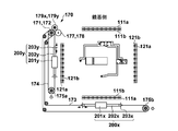
yステージ120の下面には、y軸クロスローラガイド121aと、リニアアクチュエータ200yの外包部材201yが固定されている。yプーリ172とプーリ175aの間にはyワイヤ174がかけられており、yワイヤ174とシャフト202yが同軸になるようにリニアアクチュエータ200yが配設され、ワイヤ接続部204yにyワイヤ174が接続されている。さらに、yステージ120の下面にはx軸クロスローラガイド111bが固定されている。また、リニアアクチュエータ200xの外包部材201xが不図示のブラケットを介してyステージ120に固定されている。xプーリ171は、yプーリ172と同軸で上下方向(Z方向)に重なるように配置されており、xプーリ171とプーリ175bの間にはxワイヤ173がかけられている。そして、xワイヤ173とシャフト202xが同軸になるようにリニアアクチュエータ200xが配設され、ワイヤ接続部204xにxワイヤ173が接続されている。
図4で説明したように、yステージ120をy方向へ駆動するためのリニアアクチュエータ200yの、シャフト202yを保持するフレーム203yは、たとえばブラケット181aを介してステージベース130に固定される。ステージベース130の上面には、y軸クロスローラガイド121bが配置されている。y軸クロスローラガイド121aがy軸クロスローラガイド121bを挟むように構成され、yステージ120はステージベース130に対してy方向に移動可能となっている。これにより、シャフト202yがy方向へ駆動されると、yステージ120がステージベース130に対してy方向へ移動する。
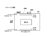
図9はyステージ120の上面を示す図である。図8に示したように、yステージ120の下面にステージ駆動のための構成部品が配置されるため、yステージ120の上面には構成部品が配置されない。したがって、yステージ120とxステージ110の間隔を狭くすることができ、ステージ装置100の高さ方向の大きさを低減できる。xステージ110には、2つのx軸クロスローラガイド111aが不図示のブラケットを介して固定され、yステージ120に固定された2つのx軸クロスローラガイド111bを外側から挟むように固定される。これにより、xステージ110がyステージ120に対してx方向に移動可能に積層される。なお、xステージ110にはブラケットを介してx軸クロスローラガイド111aが固定されるため、yステージ120では、ブラケットを通すための開口 が、x軸クロスローラガイド111bに沿って設けられている。
図10は、xステージ110、yステージ120、ステージベース130の積層状態を示す図である。xステージ110とyステージ120との間にx軸クロスローラガイド111は存在せず、図6に示した構造に比べて、ステージ装置100のz方向の厚みが減少している。また、yステージ120の下面に敷設されたxワイヤ173とリニアアクチュエータ200xのシャフト202xとを同軸に接続するために、シャフト202xの位置をyステージ120の下面よりも低い位置とする必要がある。そのためフレーム203xは、ブラケット181bを介してxステージ110に固定されている。さらに、yステージ120の下面に固定されたx軸クロスローラガイド111bとx軸クロスローラガイド111aを対向させるために、x軸クロスローラガイド111aはブラケット181dを介してxステージ110に固定される。なお、ブラケット181dは、クロスローラガイドをしっかりと保持するため、xステージ110の機構と一体的に構成されても良い。ブラケット181cは、x方向のリニアアクチュエータ200xの外包部材201xをyステージ120に対して固定するためのブラケットであり、これにより、シャフト202xの位置に合わせるように外包部材201xのz方向位置が調整される。
なお、上記実施形態および変形例のステージ装置100において、ステージベース130がyステージ120をy方向に摺動可能に支え、yステージ120がxステージ110をx方向に摺動可能に支えている。そして、ステージベース130は、顕微鏡の鏡基のzベース(不図示)に固定されてxy方向に不動である。このxy方向不動のステージベース130上に配設されたy軸クロスローラガイド121bと、yステージ120に配設されたy軸クロスローラガイド121aと、両者の間に挿入されたクロスローラとがy方向の摺動機構を構成する。摺動軸は121bと121aのy軸方向中間線であり、2本の平行なy軸方向中間線がステージベース130がyステージ120を支える支点(支線)である。この支点間隔が広いほど、広い上物を安定に支えることが出来て有利である。
図11は、上側ステージとしてのyステージ120と下側ステージとしてのステージベース130におけるクロスローラガイドの構成を示す図である。図11において、11a、11bは、yステージ120に内側のy軸クロスローラガイド121bが配設され、ステージベース130に外側のy軸クロスローラガイド121aが配設された状態を示している。また、11c、11dは、yステージ120に外側のy軸クロスローラガイド121aが配設され、ステージベース130に内側のy軸クロスローラガイド121bが配設された状態を示している。11c、11dに示すように、下側のステージ(ステージベース130)のクロスローラガイドを内側として用いた方が上側のステージ(yステージ120)を支える支点(支線)の間隔が広くなり、上側のステージをより安定に支えることが可能となる。こうした理由で、ステージ装置100では、下側のステージであるステージベース130に固定されるy軸クロスローラガイド121bは内側となり、クロスローラを挿入するための凹部(V溝)が外部方向を向くように固定される。また、上側のステージであるyステージ120に固定されるy軸クロスローラガイド121aは外側となり、クロスローラを挿入するための凹部(V溝)が内部方向を向くように固定される。xステージ110とyステージ120の間のx軸クロスローラガイド111についても、同様である。すなわち、上側のステージであるxステージ110に固定されるx軸クロスローラガイド111aは外側となり、下側のステージであるyステージ120に固定されるx軸クロスローラガイド111bは内側となる。
次に、図12A~12D、図13A~13D、図14A~14Bを参照して、図8~図10で説明したステージ装置100におけるクロスローラガイドの組み立て手順について説明する。以下に説明するように、yステージ120の同一面(図8~図10では下面)にx軸クロスローラガイド111とy軸クロスローラガイド121が配設されると、クロスローラガイドの組み立てが容易になる。
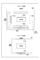
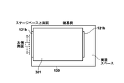
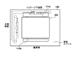
まず、図12Aに示されるように、矩形のy軸(内側用)平行治具301を外側から押さえつけるように、内側のy軸クロスローラガイド121bのペアをステージベース130の上面に固定する。続いて、図12Bに示されるように、矩形のx軸(内側用)平行治具302を外側から押さえつけるように、内側のx軸クロスローラガイド111bのペアをyステージ120の下面に固定する。
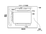
次に、図12Cに示されるように、直角治具303を用いて、2つの外側のy軸クロスローラガイド121aのうちの一方をyステージ120の下面に固定する。直角治具303の一辺を、図12Bで固定された内側のx軸クロスローラガイド111bの一方に押し当てた状態で、直角治具303の他の辺に外側のy軸クロスローラガイド121aを押し当てて固定する。これにより、内側のx軸クロスローラガイド111bに対して直角に外側のy軸クロスローラガイド121aが固定される。
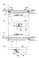
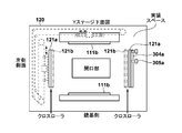
続いて、図12Dに示されるように、他の一方の外側のy軸クロスローラガイド121aを仮止めした後、yステージ120の外側のy軸クロスローラガイド121aのペアが、ステージベース130の内側のy軸クロスローラガイド121bのペアを外側から挟み込むようにyステージ120をステージベース130に載せる。その後、外側のy軸クロスローラガイド121aと内側のy軸クロスローラガイド121bの間のV溝にクロスローラを挿入する。その後、調整用の土手304aの調整ネジ305aを締める方向へ回すことで、仮止めした外側のy軸クロスローラガイド121aを所定トルクで内側に押し込み、その状態で仮止めしたy軸クロスローラガイド121aをyステージ120に固定する。なお、土手304aは、図8~図10等では記載を省略しているが、クロスローラガイドの組み立て調整において、yステージ120に設けられた外側のy軸クロスローラガイド121aを押し込むのに必要な構成であり、yステージ120の下面に設けられている。土手304aはyステージ120に取り外し可能な構成(治具)として提供されてもよい。また、調整ネジ305aは、y軸クロスローラガイド121aをyステージ120に固定するためのネジ(不図示)位置に応じて設けられていることが好ましい。
上述したように、yステージ120に固定される外側のy軸クロスローラガイド121aはステージベース130上の内側のy軸クロスローラガイド121bを挟み込むように配置される。したがって、仮止めした一方の外側のy軸クロスローラガイド121aを調整ネジ305aにより所定トルクで押し込むことで、内側のy軸クロスローラガイド121bと外側のy軸クロスローラガイド121aが適切な力で押圧しあった状態となる。この状態を図13Aに示す。この状態で、y軸クロスローラガイド121aをyステージ120にしっかりと固定することでy軸クロスローラガイドの組み立てが完了する。以上のように、土手304aは、クロスローラガイドの押圧調整機構として機能する。すなわち、土手304aは、クロスローラを挿入するための凹部が内部方向を向く外側のクロスローラガイドの一つをステージの内部方向へ押し出す力を加える。これにより、クロスローラを挿入するための凹部が外部方向を向く内側のクロスローラガイドに対して外側のクロスローラガイドを所定の押圧状態として、クロスローラガイドを固定することが可能になる。
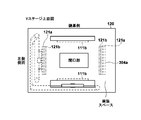
続いて、図13Bに示されるように、xステージ110の下面において、x軸(外側用)平行治具306を挟むように外側のx軸クロスローラガイド111aを固定し、その後、調整用の一方の外側のx軸クロスローラガイド111aを緩めて外側にずらし仮止めする。そして、図13Cに示されるように、xステージ110をyステージ120に積層する。上述したように、xステージ110に固定される外側のx軸クロスローラガイド111aはyステージ120上の内側のx軸クロスローラガイド111bを挟み込むように配置される。その後、外側のx軸クロスローラガイド111aと内側のx軸クロスローラガイド111bの間のV溝にクロスローラを挿入する。
クロスローラガイドの押圧調整機構としての土手304bの調整ネジ305bを締める方向へ回すことで、仮止めした外側のx軸クロスローラガイド111aを所定トルクで内側に押し込み(図13C)、その状態で仮止めしたx軸クロスローラガイド111aをxステージ110に固定する。これにより、内側のx軸クロスローラガイド111bと外側のx軸クロスローラガイド111aが適切な力で押圧しあう状態(図13D)となる。なお、土手304bは、図8~図10等では記載を省略しているが、クロスローラガイドの組み立て調整において、xステージ110に設けられた外側のx軸クロスローラガイド111aを押し込むのに必要な構成であり、xステージ110の下面に設けられている。土手304bはxステージ110に対して取り外し可能な構成(治具)として提供されてもよい。また、調整ネジ305bは、x軸クロスローラガイド111aをyステージ120に固定するためのネジ(不図示)位置に応じて設けられていることが好ましい。こうして、xステージ110に固定される外側のx軸クロスローラガイド111aはyステージ120上の内側のx軸クロスローラガイド111bを挟み込むように配置される。この状態で、外側のx軸クロスローラガイド111aをxステージ110にしっかりと固定することでx軸クロスローラガイド111の組み立てが完了する。
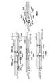
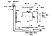
次に、図4、図5、図8、図9で説明した、x軸クロスローラガイド111、y軸クロスローラガイド121、x方向のリニアアクチュエータ200x、y方向のリニアアクチュエータ200y、手動駆動機構170、xワイヤ173、yワイヤ174のレイアウトを図14Aに示す。なお図14Aでは、yステージ120の上面、下面の区別なく構成要素の配置状態を示している。なお、手動駆動機構170は、xステージ110のx方向の移動に関しては、x摘み161(図1)のシャフトに接続されたxローラ177がx摘み161の回転操作に応じて回転する。x用伝達ローラ179xは手動駆動時にxローラ177とxプーリ171を押圧して、xローラ177の回転をxプーリ171に伝える。このように、x用伝達ローラ179xによるxローラ177とxプーリ171への押圧と解除を切り替えることにより手動駆動と電動駆動が切り替わる。yステージの120のy方向の移動に関しては、y摘み162(図1)のシャフトに接続されたyローラ178がy摘み162の回転操作に応じて回転する。y用伝達ローラ179yは手動駆動時にyローラ178とyプーリ172を押圧して、yローラ178の回転をyプーリ172に伝えるようになっている。
図14Bは、yワイヤ174の別の敷設例を示した図である。図14Bのレイアウトによれば、手動駆動機構170、リニアアクチュエータ200x、200yの配置位置の分散化が図られるため、ステージのバランスがよくなる。但し、xワイヤ173の引き回し距離が長くなる。
以上説明したように、第1実施形態のステージ装置100によれば、電動駆動時の被駆動部であるシャフト202と手動駆動時の被駆動部である駆動ワイヤの、ステージの移動方向に平行な動作軸が共通となる。これにより、バックラッシュの発生しにくいシャフトモータ(シャフトを用いるリニアモータ、シャフトが円筒の場合は円筒型リニアモータ)を用いた電動駆動と、手動摘み160を用いた手動駆動の間の切り替えにおいて、xyステージの位置が安定して保たれる。したがって、たとえば、ステージ装置100を顕微鏡ステージとして用いれば、電動駆動と手動駆動の間の切り替えにおいて、観察位置がずれることが無く、使用者はストレスを感じることなく顕微鏡観察を行うことができる。
<第2実施形態>
第1実施形態のステージ装置では、リニアアクチュエータの主要な構成としてシャフトモータ(円筒型リニアモータ)を使用している。一般にシャフトモータは、位置関係が機械的に固定されていない別部材である外包部材と、外包部材に内挿されるシャフト(円筒型のロッド部材)とよりなっている。この構成は、設計自由度は高いという利点はあるが、実装時に位置合せが必要であり、組立・調整の自動化に不向きであり、コストアップに繋がる。例えば、外包部材を駆動側ステージに、一方、円筒型ロッド部材は被駆動側ステージに、所定精度で適切な位置関係で取り付けるには、人手に依存する複雑な作業が要求される。また、シャフトと外包部材は、取り付けるまでは位置関係が固定されない別部材である為、組立前にロッド部材への傷、曲がり、金属片などの磁気による付着が生じないように適切に管理する必要もあり、これもコストアップに繋がる。第2実施形態では、上述したステージ装置への適用に適したリニアアクチュエータの提供形態を開示する。第2実施形態のリニアアクチュエータによれば、第1実施形態で説明したステージ装置の組立・調整の簡単化が実現され、製造コストが低減される。
第1実施形態のステージ装置では、リニアアクチュエータの主要な構成としてシャフトモータ(円筒型リニアモータ)を使用している。一般にシャフトモータは、位置関係が機械的に固定されていない別部材である外包部材と、外包部材に内挿されるシャフト(円筒型のロッド部材)とよりなっている。この構成は、設計自由度は高いという利点はあるが、実装時に位置合せが必要であり、組立・調整の自動化に不向きであり、コストアップに繋がる。例えば、外包部材を駆動側ステージに、一方、円筒型ロッド部材は被駆動側ステージに、所定精度で適切な位置関係で取り付けるには、人手に依存する複雑な作業が要求される。また、シャフトと外包部材は、取り付けるまでは位置関係が固定されない別部材である為、組立前にロッド部材への傷、曲がり、金属片などの磁気による付着が生じないように適切に管理する必要もあり、これもコストアップに繋がる。第2実施形態では、上述したステージ装置への適用に適したリニアアクチュエータの提供形態を開示する。第2実施形態のリニアアクチュエータによれば、第1実施形態で説明したステージ装置の組立・調整の簡単化が実現され、製造コストが低減される。
以下、第2実施形態では、第1実施形態のステージ装置100において好適に用いられるリニアアクチュエータに関して、更に説明する。なお、第2実施形態で例示されるリニアアクチュエータ200は、顕微鏡用ステージへの適用に限られるものではなく、種々の1次元ステージ、2次元ステージのリニアアクチュエータとして提供可能である。
本実施形態のリニアアクチュエータ200は、
・外包部材201と外包部材201の貫通孔にシャフト202が挿通された形態のリニアモータと(外包部材201とシャフト202の一方がコイルを有し、他方が永久磁石を有する)、
・手動操作用のワイヤとシャフト202を同軸に接続するための接続部と、
・シャフト202を取り付けるフレーム203と、を有し、
シャフト202が、外包部材201を挿通した状態で、シャフト202の軸がフレーム203の位置基準に対し、所定精度でもって組みつけられた状態で提供される一体型リニアアクチュエータである。図3Aに示されるリニアアクチュエータ200は、実装の結果として、上記所定精度が得られるリニアアクチュエータが構成される例を示している。以下、本実施形態のリニアアクチュエータ200の構成例について説明する。
・外包部材201と外包部材201の貫通孔にシャフト202が挿通された形態のリニアモータと(外包部材201とシャフト202の一方がコイルを有し、他方が永久磁石を有する)、
・手動操作用のワイヤとシャフト202を同軸に接続するための接続部と、
・シャフト202を取り付けるフレーム203と、を有し、
シャフト202が、外包部材201を挿通した状態で、シャフト202の軸がフレーム203の位置基準に対し、所定精度でもって組みつけられた状態で提供される一体型リニアアクチュエータである。図3Aに示されるリニアアクチュエータ200は、実装の結果として、上記所定精度が得られるリニアアクチュエータが構成される例を示している。以下、本実施形態のリニアアクチュエータ200の構成例について説明する。
[構成例1]
図15A~15Dのリニアアクチュエータ200aは、図3A~図3Dで説明したリニアアクチュエータ200のワイヤ接続部204に改造を加えたものである。図3A~図3Dに示した構成では、実装時にワイヤ接続部をフレーム203を挟んでシャフト202に取り付けるもので、ワイヤ固定ネジ205の回転方向の位置(位相)は、実装上の都合により任意の位置にすることが出来る。これに対して、図15A~15Dに示される一体型リニアアクチュエータの構成では、ワイヤ固定部(接続カバー222とワイヤ固定ネジ205)がシャフト固定部(シャフト固定ネジ221)に回転可能に構成されている。したがって、一体型リニアアクチュエータとして取り付けた後に、ワイヤ固定ネジ205の位置を回転して、好適な位置でワイヤを固定することが可能となっている。なお、図15A~15Dでも図3A~図3Dと同様に、ワイヤ接続部204は、シャフトの両端の側において、シャフトの軸と同軸になるように駆動ワイヤを装着可能なワイヤ接続機構を提供する構成である。
図15A~15Dのリニアアクチュエータ200aは、図3A~図3Dで説明したリニアアクチュエータ200のワイヤ接続部204に改造を加えたものである。図3A~図3Dに示した構成では、実装時にワイヤ接続部をフレーム203を挟んでシャフト202に取り付けるもので、ワイヤ固定ネジ205の回転方向の位置(位相)は、実装上の都合により任意の位置にすることが出来る。これに対して、図15A~15Dに示される一体型リニアアクチュエータの構成では、ワイヤ固定部(接続カバー222とワイヤ固定ネジ205)がシャフト固定部(シャフト固定ネジ221)に回転可能に構成されている。したがって、一体型リニアアクチュエータとして取り付けた後に、ワイヤ固定ネジ205の位置を回転して、好適な位置でワイヤを固定することが可能となっている。なお、図15A~15Dでも図3A~図3Dと同様に、ワイヤ接続部204は、シャフトの両端の側において、シャフトの軸と同軸になるように駆動ワイヤを装着可能なワイヤ接続機構を提供する構成である。
図15Aは、リニアアクチュエータ200aの外観を示す図である。外包部材201の貫通孔にシャフト202が挿通されたシャフトモータにおいて、シャフト202の両端が、ワイヤ接続部204によりフレーム203に所定精度で固定される。たとえば、フレーム203はコの字形状を有し、底面パネル2031とその両側の側面パネル2032を有し、シャフト202の両端が側面パネル2032に所定精度で固定される。ワイヤ接続部204は、2つの側面パネル2032に形成された所定精度の貫通孔(図3A~図3Dと異なり大きめでない)を通してシャフト202の両端部をネジ止めすることでシャフト202を2つの側面パネル2032の間に固定するネジ部(図15Bのシャフト固定ネジ221)を有する。また、ワイヤ接続部204は、そのネジ部と同軸となるように駆動ワイヤ(xワイヤ173、yワイヤ174)の端部を固定するワイヤ固定部(図15Bの接続カバー222)を有する。以下、具体的に説明する。
リニアアクチュエータ200aのワイヤ接続部204は、図15Bに示されるように、シャフト固定ネジ221、接続カバー222、接続カバー固定ネジ223を有する。図15Cに示されるように、シャフト固定ネジ221はシャフト202の端部に設けられたネジ部213とのネジ締めによりフレーム203の側面パネル2032にシャフト202を固定する。シャフト固定ネジ221のネジ部に隣接して、側面パネル2032の貫通孔と嵌合する円筒部2211が設けられており、シャフト202の軸とシャフト固定ネジ221の軸の位置が所定の精度で同軸となるようにしている。接続カバー222はシャフト固定ネジ221を内包する凹部を有し、その凹部の反対側の面には駆動ワイヤ15を挿入するための穴を有している。接続カバー222は接続カバー固定ネジ223によりシャフト固定ネジ221に固定される。また、接続カバー222に挿入された駆動ワイヤ15の端部は、ワイヤ固定ネジ205により接続カバー222に固定される。なお、駆動ワイヤ15の先端部には所定径のスリーブが装着されており、駆動ワイヤ15とシャフト202の軸をより正確に一致させるようにしている。
以上のようなリニアアクチュエータ200aによれば、駆動ワイヤ15がシャフト202と同軸の関係を有して接続される。また、接続カバー222は、接続カバー固定ネジ223により、ワイヤ固定ネジ205へのアクセスが容易となる任意の回転位置でシャフト固定ネジ221に固定することができ、便利である。なお、図3A~図3Dでも説明したように、穴部212への駆動ワイヤ15の固定は、図示の形態に限られるものではなく、いかなる構造が用いられてもよい。たとえば、カシメにより駆動ワイヤ15の端部が穴部212に固定されてもよい。または、図15Bに示すように、円筒穴を有する円筒ピン1501の穴部に駆動ワイヤの端部を差し込み、ネジまたはカシメにより固定し、この駆動ワイヤ15が一端に接続された円筒ピンの他端を穴部212に挿入し、ワイヤ固定ネジ205で固定しても良い。これは、後述の構成例2以降のリニアアクチュエータについても同様である。
図15Dは、図15Aに示されるリニアアクチュエータ200aにおいて、フレーム203が側面パネル2032よりさらに外側に延びた底面パネル2031を有するものである。図15A、図15Dのいずれの形態においても、ワイヤ接続部204が側面パネル2032から伸び出ており、ワイヤ接続部204のワイヤを接続する位置がシャフト202の軸の延長上にある。
図20は、リニアアクチュエータ200aにおける位置基準を説明する図である。フレーム203は、2つの側面パネル2032に設けられた貫通孔によって規定される軸位置および軸方向に対して所定の位置関係を有する軸位置基準および軸方向基準としての基準凸部2035と基準凸部2036を有する。ここで、軸位置とは、フレーム203に固定されたシャフト202の中心軸の位置であり、軸方向とはその中心軸の方向である。基準凸部2035により、図20に示されるように、基準凸部2035の頂点位置からシャフト202の中心位置(同軸位置)までの距離Aが規定される。また、取り付け穴の周囲の基準凸部2036により、シャフト202の中心位置までの距離Bが規定される。こうして、基準凸部2035、2036により、シャフト202の軸位置が規定される。また、底面パネルの同じ辺上にある基準凸部2035の頂点を結ぶ線は、シャフト202の軸方向を示す(シャフト202の軸方向と平行である)。
このようなフレーム203の基準を用いることで、リニアアクチュエータ200aを精度よく、容易に、第1実施形態のステージ装置100へ組み込むことができる。なお、以下に示す構成例においても、フレーム203は同様の位置基準、軸方向基準を有する。
[構成例2]
図16A,16Bは、リニアアクチュエータ200の更に別の構成例であるリニアアクチュエータ200bを示す図である。図16Aはリニアアクチュエータ200bの外観を示す図である。図16Bはリニアアクチュエータ200bの分解図である。外包部材201の貫通孔にシャフト202が挿通され、シャフト202の両端が、ワイヤ接続部204によりフレーム203に所定精度で固定されている。リニアアクチュエータ200bのワイヤ接続部204では、一方の端部にシャフト202のネジ部213に適合したネジ部が形成され、他方の端部にはフック部231が形成されている。ネジ部により、2つの側面パネル2032に形成された所定精度の貫通孔を通してシャフト202の両端部がネジ止めされ、シャフト202が2つの側面パネル2032の間に所定精度で固定されている。ワイヤ接続機構の端部としてのフック部231は、端部がリング状に形成された駆動ワイヤ15をひっかけるためにフック形状を有している。フック部231に、駆動ワイヤ15の端部に形成されたリング1502をひっかけることにより、シャフト202とワイヤが同軸に接続されることになる。
図16A,16Bは、リニアアクチュエータ200の更に別の構成例であるリニアアクチュエータ200bを示す図である。図16Aはリニアアクチュエータ200bの外観を示す図である。図16Bはリニアアクチュエータ200bの分解図である。外包部材201の貫通孔にシャフト202が挿通され、シャフト202の両端が、ワイヤ接続部204によりフレーム203に所定精度で固定されている。リニアアクチュエータ200bのワイヤ接続部204では、一方の端部にシャフト202のネジ部213に適合したネジ部が形成され、他方の端部にはフック部231が形成されている。ネジ部により、2つの側面パネル2032に形成された所定精度の貫通孔を通してシャフト202の両端部がネジ止めされ、シャフト202が2つの側面パネル2032の間に所定精度で固定されている。ワイヤ接続機構の端部としてのフック部231は、端部がリング状に形成された駆動ワイヤ15をひっかけるためにフック形状を有している。フック部231に、駆動ワイヤ15の端部に形成されたリング1502をひっかけることにより、シャフト202とワイヤが同軸に接続されることになる。
[構成例3]
図17A~17Bは、リニアアクチュエータ200の更に別の構成例であるリニアアクチュエータ200cを示す図である。図17Aはリニアアクチュエータ200cの外観を示す斜視図、図17Bにおいて17bはリニアアクチュエータ200cの断面図、17cは、シャフト固定部およびワイヤ接続部の詳細な断面図である。リニアアクチュエータ200cのフレーム203は、底面パネル2031に直交して対向する側面パネル2032の対と、側面パネル2032の対を挟むように設けられた、底面パネル2031に直交して対向する第2側面パネル2033の対とを有する。
図17A~17Bは、リニアアクチュエータ200の更に別の構成例であるリニアアクチュエータ200cを示す図である。図17Aはリニアアクチュエータ200cの外観を示す斜視図、図17Bにおいて17bはリニアアクチュエータ200cの断面図、17cは、シャフト固定部およびワイヤ接続部の詳細な断面図である。リニアアクチュエータ200cのフレーム203は、底面パネル2031に直交して対向する側面パネル2032の対と、側面パネル2032の対を挟むように設けられた、底面パネル2031に直交して対向する第2側面パネル2033の対とを有する。
外包部材201の貫通孔にシャフト202が挿通された状態で、シャフト202の両端が、シャフト固定ネジ221aによりフレーム203の側面パネル2032に固定される。フレーム203の底面パネル2031は、側面パネル2032の位置よりもさらに外側へ延びており、その底面パネル2031の両端には第2側面パネル2033が設けられている。第2側面パネル2033には、ワイヤ接続部204aにより駆動ワイヤ15が接続される。
17cに示されるように、シャフト202は両端にネジ部213を有し、シャフト固定ネジ221aにより側面パネル2032を挟んでネジ締めされ、側面パネル2032に固定される。また、ワイヤ接続部204aの一方の端部にネジ部が設けられており、固定ネジ232により第2側面パネル2033を挟んでネジ締めされ、第2側面パネル2033に固定される。側面パネル2032と第2側面パネル2033の穴は、シャフト202とワイヤが同軸に配置されるように形成されている。
なお、上記の例では、ワイヤ接続部204aを固定するための第2側面パネル2033が、側面パネル2032の位置からさらに外側に延びた底面パネル2031に設けられた例を説明したが、これに限られるものではない。シャフト202と駆動ワイヤ15が同軸となるようにシャフト202と駆動ワイヤ15を固定する構成であればよいので種々の変形が可能である。たとえば、側面パネル2032の両側と上側の3辺の何れかよりシャフト202の軸方向に延びる部材とその先に第2側面パネル2033が設けられた構成でもよい。
[構成例4]
図18A~18Cは、リニアアクチュエータ200の更に別の変形例としてのリニアアクチュエータ200dを示す図である。図18Aはリニアアクチュエータ200dの外観を示す斜視図、図18Bはリニアアクチュエータ200dの分解図、図18Cはフレーム203の変形例を示す図である。リニアアクチュエータ200dでは、外包部材201の貫通孔にシャフト202が挿通されたシャフトモータにおいて、シャフト202がその両端にワイヤ接続部204cを有する構成となっている。
図18A~18Cは、リニアアクチュエータ200の更に別の変形例としてのリニアアクチュエータ200dを示す図である。図18Aはリニアアクチュエータ200dの外観を示す斜視図、図18Bはリニアアクチュエータ200dの分解図、図18Cはフレーム203の変形例を示す図である。リニアアクチュエータ200dでは、外包部材201の貫通孔にシャフト202が挿通されたシャフトモータにおいて、シャフト202がその両端にワイヤ接続部204cを有する構成となっている。
シャフト202は、ワイヤ接続部204cのネジ部213aとシャフト固定ナット233によりフレーム203の側面パネル2032に固定される。側面パネル2032は、ワイヤ接続部204cを有するシャフト202を受け入れるために、所定精度で形成されたU字型の切り込みを有している。すなわち、シャフト202をU字型の切り込みにしっかりと差し込むことで、シャフト202の軸位置とフレーム203との位置関係が図20に示すのと同程度に維持されるものである。また、ワイヤ接続部204cのネジ部213aよりも先端側の端面には、ワイヤを受け入れる穴部212が設けられている。穴部212に駆動ワイヤ15を挿入してワイヤ固定ネジ205で径方向に締め付けることで、駆動ワイヤ15がワイヤ接続部204cに固定される。
なお、以上のような、ワイヤ接続部が一体化されたシャフト202をステージに固定するためのフレーム203として、図18Cに示されるような、分離されたフレーム203aが用いられてもよい。分離されたフレーム203aは、底面パネル2031aと側面パネル2032aからなるL字の形状を有する。ただし、分離されたフレーム203aとシャフト202の位置関係は、所定精度で保持されることが必要である。なお、このような分離型のフレームは図15A~15D,図16A~16B、図17A~17B、図18A~18Cに示したリニアアクチュエータにも適用できる。なお、図3A~図3Dに示すシャフトモータを使用する場合にも、分離型のフレームは実装上、便利であり、分離されたフレーム203aはステージ側に作り込まれていてもよい。
[構成例5]
図19A~19Dは、リニアアクチュエータ200の更に別の変形例としてのリニアアクチュエータ200eを示す図である。リニアアクチュエータ200eのワイヤ接続機構は、駆動ワイヤの固定位置を、シャフト202の軸方向に移動させるための構成を含み、これにより駆動ワイヤ15のテンションを調整可能としたものである。一般に駆動ワイヤのテンション調整は、たとえば図14Aにおいて、プーリ175aのy方向への移動やプーリ175bのx方向への移動によりなされる。しかるに、プーリ移動調整機構の追加を伴うと同時に、テンション調整時のアクセス路を確保する事が必要になり、コストアップに繋がる。これに対し、リニアアクチュエータ200eでは、以下に示すような構成によりフレーム203において駆動ワイヤのテンション調整が可能となる。そのため、使用者はより容易にテンション調整を実施できる。
図19A~19Dは、リニアアクチュエータ200の更に別の変形例としてのリニアアクチュエータ200eを示す図である。リニアアクチュエータ200eのワイヤ接続機構は、駆動ワイヤの固定位置を、シャフト202の軸方向に移動させるための構成を含み、これにより駆動ワイヤ15のテンションを調整可能としたものである。一般に駆動ワイヤのテンション調整は、たとえば図14Aにおいて、プーリ175aのy方向への移動やプーリ175bのx方向への移動によりなされる。しかるに、プーリ移動調整機構の追加を伴うと同時に、テンション調整時のアクセス路を確保する事が必要になり、コストアップに繋がる。これに対し、リニアアクチュエータ200eでは、以下に示すような構成によりフレーム203において駆動ワイヤのテンション調整が可能となる。そのため、使用者はより容易にテンション調整を実施できる。
リニアアクチュエータ200eは、シャフト202を側面パネル2032に固定し、xワイヤ173またはyワイヤ174を接続するとともに、接続されたワイヤのテンションの調整を可能とするテンション調整部240を有する。図19Aはリニアアクチュエータ200eの外観を示す図、図19Bはシャフト固定部およびテンション調整部240の分解構成図、図19Cはテンション調整部の組み立て状態図、図19Dはテンション調整部240の断面構成図を示す。
図19B、19Dに示されるように、シャフト202は、その端面に設けられたネジ部213とシャフト固定ネジ221によって側面パネル2032にネジ締めされ、所定精度で固定される。テンション調整部240は、調整ネジ部241、調整スリーブ固定ナット242、ワイヤ固定部243、テンション調整スリーブ244を有する。調整ネジ部241は、シャフト固定ネジ221を収容する凹部を有する円筒部分2411aと、調整スリーブ固定ナット242およびテンション調整スリーブ244に形成されたネジに適合するネジ部分2411bとを有する。また、円筒部分2411aには、固定ネジ223のためのネジ穴2411cが設けられている。
まず、シャフト固定ネジ221で、シャフト202をフレーム203(側面パネル2032)に所定精度で固定する。その後、調整ネジ部241の凹部でシャフト固定ネジ221を覆い、収容した状態で固定ネジ223により、調整ネジ部241をシャフト固定ネジ221に固定する。ワイヤ固定部243は、駆動ワイヤ15を差し込むための穴を有し、テンション調整スリーブ244の貫通孔を通して穴に差し込まれた駆動ワイヤ15をワイヤ固定ネジ205により固定する。ワイヤ固定部243はテンション調整スリーブ244の内部に収容される。そして、テンション調整スリーブ244(内側にネジ部分を有する)を回して、調整ネジ部241のネジ部分にねじ込み、テンション調整スリーブ244の位置を変化させることでワイヤ固定部243の位置を軸方向に(矢印1901の方向に)移動させ、駆動ワイヤ15のテンションを調整することができる。すなわち、テンション調整スリーブ244の位置の変化によりリニアアクチュエータ200eの両側にあるワイヤ固定部243の間の距離が変化する。テンション調整終了後は、調整スリーブ固定ナット242により、テンション調整スリーブ244を締め付け、調整ネジ部241における位置を固定する。こうして、駆動ワイヤ15のテンションを調整することができる。猶、テンション調整機構は、リニアアクチュエータのシャフトの両端に具備される様に説明したが、片側のみに有っても良い。
なお、上述したテンション調整部240は、図16Aのようにワイヤ接続部をフック形状にした場合、図17Aのように別の側面パネルにワイヤ接続部を設けた場合、図18Aのようにシャフトの両端にワイヤ接続部を設けた場合など、何れの形態にも適用できる。
本発明は上記実施の形態に制限されるものではなく、本発明の精神及び範囲から離脱することなく、様々な変更及び変形が可能である。従って、本発明の範囲を公にするために、以下の請求項を添付する。
本願は、2016年6月9日提出の日本国特許出願特願2016-115693を基礎として優先権を主張するものであり、その記載内容の全てを、ここに援用する。
Claims (30)
- 第1のステージと、
前記第1のステージの面上を第1の方向に相対的に移動する第2のステージと、
手動による駆動力により、前記第2のステージを前記第1の方向へ相対的に移動させるための第1の被駆動部を駆動する第1の駆動手段と、
電動による駆動力により、前記第2のステージを前記第1の方向へ相対的に移動させるための第2の被駆動部を駆動する第2の駆動手段と、を備え、
前記第1の被駆動部と前記第2の被駆動部の少なくとも一部が共通の動作軸を有することを特徴とするステージ装置。 - 前記共通の動作軸は、前記第1の方向と平行であることを特徴とする請求項1に記載のステージ装置。
- 前記第1の方向は、前記第1および第2のステージに配置されたクロスローラガイドにより規定されることを特徴とする請求項1または2に記載のステージ装置。
- 前記第2の駆動手段は、外包部材と前記外包部材を貫通する穴に挿通されたシャフトを有するシャフトモータの外包部材であり、前記第2の被駆動部は前記シャフトモータの前記シャフトであることを特徴とする請求項1乃至3のいずれか1項に記載のステージ装置。
- 前記第1の駆動手段は、ユーザの手動操作に応じて回転するプーリを有し、前記第1の被駆動部は、前記プーリにより移動するワイヤであることを特徴とする請求項4に記載のステージ装置。
- 前記シャフトを前記第1のステージに固定する固定手段をさらに備え、
前記第2の駆動手段である前記外包部材と前記第1の駆動手段は前記第2のステージに固定され、
前記第1の被駆動部である前記ワイヤが前記シャフトの軸の延長上の位置で、前記シャフトの軸と同軸になるように接続されていることを特徴とする請求項5に記載のステージ装置。 - 前記固定手段は、前記シャフトの両端を固定するための2つの側面パネルと、該2つの側面パネルを固定する底面パネルを有するフレームを含むことを特徴とする請求項6に記載のステージ装置。
- 前記外包部材は前記第2のステージに固定され、前記シャフトは前記第1のステージに固定され、前記シャフトの両端部に前記ワイヤが接続されることを特徴とする請求項5に記載のステージ装置。
- 前記フレームは、前記第1のステージに固定されることを特徴とする請求項7に記載のステージ装置。
- 前記シャフトと前記外包部材の一方がコイルを含み、他方が磁石を含むことを特徴とする請求項4乃至9のいずれか1項に記載のステージ装置。
- 前記シャフトの断面が円形状であることを特徴とする請求項4乃至10のいずれか1項に記載のステージ装置。
- 前記第1のステージの面上に前記第2のステージを前記第1の方向へ移動可能に積層するためのクロスローラガイドであって、前記第1のステージに配置されるクロスローラガイドは、クロスローラを挿入するための凹部がステージの外部方向を向き、前記第2のステージに配置されるクロスローラガイドはクロスローラを挿入するための凹部が内部方向を向くように配置されていることを特徴とする請求項1乃至11のいずれか1項に記載のステージ装置。
- 前記第2のステージの面上を前記第1の方向とは異なる第2の方向に相対的に移動する第3のステージと、
手動による駆動力により、前記第3のステージを前記第2の方向へ相対的に移動させるための第3の被駆動部を駆動する第3の駆動手段と、
電動による駆動力により、前記第3のステージを前記第2の方向へ相対的に移動させるための第4の被駆動部を駆動する第4の駆動手段とをさらに備え、
前記第3の被駆動部と前記第4の被駆動部の少なくとも一部が共通の動作軸を有することを特徴とする請求項1に記載のステージ装置。 - 前記第3の被駆動部と前記第4の被駆動部の共通の動作軸は、前記第2の方向に平行であることを特徴とする請求項13に記載のステージ装置。
- 前記第1の駆動手段及び第3の駆動手段と、前記第2の駆動手段と、前記第4の駆動手段とは、それぞれ前記第2のステージの異なる3つの辺に分散して配置されることを特徴とする請求項13または14に記載のステージ装置。
- 前記第1および第2の駆動手段と前記第1の方向の移動を規定するクロスローラガイドが前記第2のステージの前記第1のステージと対向する面に設けられ、
前記第3および第4の駆動手段と前記第2の方向の移動を規定するクロスローラガイドが前記第2のステージの前記第3のステージと対向する面に設けられることを特徴とする請求項13乃至15のいずれか1項に記載のステージ装置。 - 前記第1および第2の駆動手段と前記第1の方向の移動を規定するクロスローラガイド、および前記第3および第4の駆動手段と前記第2の方向の移動を規定するクロスローラガイドが、前記第2のステージの前記第1のステージと対向する面に設けられることを特徴とする請求項13乃至15のいずれか1項に記載のステージ装置。
- 前記第2のステージの面上に前記第3のステージを前記第2の方向へ移動可能に積層するためのクロスローラガイドであって、前記第2のステージに配置されるクロスローラガイドは、クロスローラを挿入するための凹部がステージの外部方向を向き、前記第3のステージに配置されるクロスローラガイドはクロスローラを挿入するための凹部が内部方向を向くように配置されていることを特徴とする請求項13に記載のステージ装置。
- クロスローラを挿入するための凹部が内部方向を向くクロスローラガイドの一つを、前記内部方向へ押し出す力を加えることにより、クロスローラを挿入するための凹部が外部方向を向くクロスローラガイドに対して所定の押圧状態とするための押圧調整手段をさらに備えることを特徴とする請求項12または18に記載のステージ装置。
- 顕微鏡のためのステージ装置であって、
前記顕微鏡に固定されるステージベースと、
前記ステージベースの面上を第1の方向に相対的に移動するyステージと、
観察対象のスライドを載置して、前記yステージの面上を前記第1の方向に直交する第2の方向に相対的に移動するxステージと、
電動による駆動力により、前記yステージを前記第1の方向へ相対的に移動させるための第1のシャフトを駆動する第1のシャフトモータと、
電動による駆動力により、前記xステージを前記第2の方向へ相対的に移動させるための第2のシャフトを駆動する第2のシャフトモータと、
手動による駆動力により、前記yステージを前記第1の方向へ移動させるための第1のワイヤを移動させる駆動手段と、手動による駆動力により、前記xステージを前記第2の方向へ移動させるための第2のワイヤを移動させる駆動手段と、を備え、
前記第1のワイヤが前記第1のシャフトと同軸になるように敷設され、
前記第2のワイヤが前記第2のシャフトと同軸になるように敷設されていることを特徴とする顕微鏡ステージ。 - 外包部材と、
前記外包部材を貫通する穴に挿通されるシャフトと、
前記シャフトの両端の側において、前記シャフトの軸と同軸になるようにワイヤを装着可能なワイヤ接続機構と、を備えることを特徴とするリニアアクチュエータ。 - 前記外包部材と前記シャフトの一方がコイルを含み、他方が磁石を含むことを特徴とする請求項21に記載のリニアアクチュエータ。
- 前記ワイヤ接続機構が前記シャフトの両端部に設けられていることを特徴とする請求項21または22に記載のリニアアクチュエータ。
- 底面パネルと、前記底面パネルに直交して対向する2つの側面パネルとを有するフレームをさらに備え、
前記ワイヤ接続機構は、
前記2つの側面パネルに形成された貫通孔を通して前記シャフトの両端部をネジ止めすることで前記シャフトを前記2つの側面パネルの間に固定するネジ部と、
前記ネジ部と同軸となるようにワイヤを固定するワイヤ固定部を有することを特徴とする請求項21または22に記載のリニアアクチュエータ。 - 前記ネジ部は、前記シャフトの軸と前記ネジ部の軸の位置が所定の精度で同軸となるように、前記側面パネルの前記貫通孔と嵌合する円筒部を含むことを特徴とする請求項24に記載のリニアアクチュエータ。
- 底面パネルと、前記底面パネルに直交して対向する側面パネルとを有するフレームをさらに備え、
前記ワイヤ接続機構は前記側面パネルから伸び出ており、前記ワイヤ接続機構のワイヤを接続する位置は、前記シャフトの軸の延長上にあることを特徴とする請求項21に記載のリニアアクチュエータ。 - 底面パネルと、前記底面パネルに直交して対向する第1の側面パネルの対と、前記第1の側面パネルの対を挟むように設けられた前記底面パネルに直交して対向する第2の側面パネルの対とを有するフレームをさらに備え、
前記第1の側面パネルに形成された貫通孔を通して前記シャフトの両端部をネジ止めすることで前記シャフトを前記第1の側面パネルの対の間に固定するネジ部と、
前記ネジ部と同軸となるようにワイヤを前記第2の側面パネルに固定するワイヤ固定部とを有することを特徴とする請求項21または22に記載のリニアアクチュエータ。 - 前記フレームは、前記2つの側面パネルに設けられた前記貫通孔によって規定される軸位置および軸方向に対して所定の位置関係を有する位置基準および軸方向基準を有することを特徴とする請求項24または25に記載のリニアアクチュエータ。
- 前記ワイヤ接続機構は、端部がリング状に形成されたワイヤをひっかけるフック形状を有することを特徴とする請求項21に記載のリニアアクチュエータ。
- 前記ワイヤ接続機構は、前記ワイヤの固定位置を、前記シャフトの軸方向に移動させる移動手段をさらに備え、前記ワイヤのテンションを調整可能としたことを特徴とする請求項21乃至29のいずれか1項に記載のリニアアクチュエータ。
Priority Applications (1)
| Application Number | Priority Date | Filing Date | Title |
|---|---|---|---|
| US16/211,468 US11137589B2 (en) | 2016-06-09 | 2018-12-06 | Stage apparatus and linear actuator |
Applications Claiming Priority (2)
| Application Number | Priority Date | Filing Date | Title |
|---|---|---|---|
| JP2016115693A JP6722048B2 (ja) | 2016-06-09 | 2016-06-09 | ステージ装置およびリニアアクチュエータ |
| JP2016-115693 | 2016-06-09 |
Related Child Applications (1)
| Application Number | Title | Priority Date | Filing Date |
|---|---|---|---|
| US16/211,468 Continuation US11137589B2 (en) | 2016-06-09 | 2018-12-06 | Stage apparatus and linear actuator |
Publications (1)
| Publication Number | Publication Date |
|---|---|
| WO2017212908A1 true WO2017212908A1 (ja) | 2017-12-14 |
Family
ID=60577908
Family Applications (1)
| Application Number | Title | Priority Date | Filing Date |
|---|---|---|---|
| PCT/JP2017/019127 Ceased WO2017212908A1 (ja) | 2016-06-09 | 2017-05-23 | ステージ装置およびリニアアクチュエータ |
Country Status (3)
| Country | Link |
|---|---|
| US (1) | US11137589B2 (ja) |
| JP (1) | JP6722048B2 (ja) |
| WO (1) | WO2017212908A1 (ja) |
Families Citing this family (4)
| Publication number | Priority date | Publication date | Assignee | Title |
|---|---|---|---|---|
| JP6895306B2 (ja) | 2017-04-26 | 2021-06-30 | キヤノン株式会社 | ステージ装置 |
| US10845699B2 (en) * | 2017-11-29 | 2020-11-24 | Taiwan Semiconductor Manufacturing Co., Ltd. | Method for forming photomask and photolithography method |
| JP7137373B2 (ja) * | 2018-06-25 | 2022-09-14 | キヤノンプレシジョン株式会社 | ステージ装置及び顕微鏡システム |
| CN110161672B (zh) * | 2019-06-11 | 2022-05-10 | 长春长光辰英生物科学仪器有限公司 | 一种粗微调结合的精密位移装置 |
Citations (4)
| Publication number | Priority date | Publication date | Assignee | Title |
|---|---|---|---|---|
| JP2006178204A (ja) * | 2004-12-22 | 2006-07-06 | Olympus Corp | 顕微鏡ステージ |
| JP2013160960A (ja) * | 2012-02-07 | 2013-08-19 | Nsk Ltd | マニピュレータシステム及び微小操作対象物の操作方法 |
| WO2014069190A1 (ja) * | 2012-10-05 | 2014-05-08 | 株式会社ミラック光学 | 手動ステージ用電動化ユニット、及び電動化ユニット付き手動ステージ |
| JP2016200803A (ja) * | 2015-04-08 | 2016-12-01 | キヤノン株式会社 | ステージ装置および顕微鏡 |
Family Cites Families (18)
| Publication number | Priority date | Publication date | Assignee | Title |
|---|---|---|---|---|
| US4956944A (en) | 1987-03-19 | 1990-09-18 | Canon Kabushiki Kaisha | Polishing apparatus |
| US4974368A (en) | 1987-03-19 | 1990-12-04 | Canon Kabushiki Kaisha | Polishing apparatus |
| US5705789A (en) * | 1995-09-29 | 1998-01-06 | Litel Instruments, Inc. | Stabilization of parallel transport mirror system |
| US5702662A (en) * | 1995-09-29 | 1997-12-30 | Litel Instruments, Inc. | Process for ablating high density vias in flexible substrate |
| US7024046B2 (en) * | 2000-04-18 | 2006-04-04 | Real Time Image Ltd. | System and method for the lossless progressive streaming of images over a communication network |
| JP4814438B2 (ja) * | 2001-05-02 | 2011-11-16 | 日本トムソン株式会社 | リニアモータを内蔵したステージ装置 |
| US7075323B2 (en) * | 2004-07-29 | 2006-07-11 | Applied Materials, Inc. | Large substrate test system |
| US7230676B1 (en) * | 2006-03-13 | 2007-06-12 | Asml Netherlands B.V. | Lithographic apparatus and device manufacturing method |
| US7659507B2 (en) * | 2006-10-02 | 2010-02-09 | Jeol Ltd. | Automatic method of axial adjustments in electron beam system |
| US10330581B2 (en) * | 2007-09-17 | 2019-06-25 | Rave Llc | Debris removal from high aspect structures |
| US10384238B2 (en) * | 2007-09-17 | 2019-08-20 | Rave Llc | Debris removal in high aspect structures |
| WO2009121051A2 (en) * | 2008-03-28 | 2009-10-01 | Nordson Corporation | X-ray inspection systems and methods |
| US8101911B2 (en) * | 2008-11-04 | 2012-01-24 | ICT Integrated Circuit Testing Gesellschaft für Halbleiterprüftechnik mbH | Method and device for improved alignment of a high brightness charged particle gun |
| JP5349093B2 (ja) * | 2009-03-16 | 2013-11-20 | 株式会社日立ハイテクノロジーズ | プロキシミティ露光装置、プロキシミティ露光装置の基板位置決め方法、及び表示用パネル基板の製造方法 |
| EP2488911B1 (en) | 2009-10-16 | 2017-07-26 | Thorlabs, Inc. | Motorized stage |
| US8467126B2 (en) * | 2010-05-27 | 2013-06-18 | Valley Precision, Inc. | Stage driver for movable stages |
| KR20140084238A (ko) * | 2011-10-27 | 2014-07-04 | 더 유니버시티 오브 브리티쉬 콜롬비아 | 변위 장치 및 변위 장치의 제조, 사용 그리고 제어를 위한 방법 |
| WO2014123177A1 (ja) * | 2013-02-08 | 2014-08-14 | ピーエスフォー ルクスコ エスエイアールエル | 半導体装置の製造方法 |
-
2016
- 2016-06-09 JP JP2016115693A patent/JP6722048B2/ja active Active
-
2017
- 2017-05-23 WO PCT/JP2017/019127 patent/WO2017212908A1/ja not_active Ceased
-
2018
- 2018-12-06 US US16/211,468 patent/US11137589B2/en active Active
Patent Citations (4)
| Publication number | Priority date | Publication date | Assignee | Title |
|---|---|---|---|---|
| JP2006178204A (ja) * | 2004-12-22 | 2006-07-06 | Olympus Corp | 顕微鏡ステージ |
| JP2013160960A (ja) * | 2012-02-07 | 2013-08-19 | Nsk Ltd | マニピュレータシステム及び微小操作対象物の操作方法 |
| WO2014069190A1 (ja) * | 2012-10-05 | 2014-05-08 | 株式会社ミラック光学 | 手動ステージ用電動化ユニット、及び電動化ユニット付き手動ステージ |
| JP2016200803A (ja) * | 2015-04-08 | 2016-12-01 | キヤノン株式会社 | ステージ装置および顕微鏡 |
Also Published As
| Publication number | Publication date |
|---|---|
| JP6722048B2 (ja) | 2020-07-15 |
| US11137589B2 (en) | 2021-10-05 |
| JP2017219775A (ja) | 2017-12-14 |
| US20190107703A1 (en) | 2019-04-11 |
Similar Documents
| Publication | Publication Date | Title |
|---|---|---|
| WO2017212908A1 (ja) | ステージ装置およびリニアアクチュエータ | |
| JP6312621B2 (ja) | レンズ駆動装置 | |
| EP3732522B1 (en) | Mirror alignment in optical scientific instruments | |
| JP2013501250A (ja) | 光学要素のための保持装置 | |
| WO2006035582A1 (ja) | カメラモジュール及びこのカメラモジュールを用いた携帯端末 | |
| JP2014014256A (ja) | 振動波駆動装置、二次元駆動装置、画像振れ補正装置、交換レンズ、撮像装置、及び自動ステージ | |
| US20110134549A1 (en) | Barrel unit and image pickup apparatus | |
| JP2009053671A (ja) | Xyステージ、および撮影装置 | |
| KR20060042172A (ko) | 광학 모듈 및 카메라 모듈 | |
| JP2020057001A (ja) | レンズのようなエレメントの位置を精密調整するための移動調節可能な機械式のホルダ | |
| JP2018185433A (ja) | ステージ装置 | |
| JP2020187297A (ja) | 光学シフト装置および光学機器 | |
| JP2002333564A (ja) | 光学機器 | |
| JP5117322B2 (ja) | プロジェクタ用絞り装置 | |
| JP2009251189A (ja) | レンズ駆動装置収納構造及びレンズ駆動装置 | |
| JP5117314B2 (ja) | プロジェクタ用絞り装置 | |
| US7463414B2 (en) | Microscope | |
| JP5117315B2 (ja) | プロジェクタ用絞り装置 | |
| JP5090286B2 (ja) | プロジェクタ用絞り装置 | |
| JP2022534347A (ja) | カメラモジュール及びカメラモジュールの使用方法 | |
| JP2020003527A (ja) | ステージ装置及び顕微鏡システム | |
| JP5430386B2 (ja) | 撮像装置 | |
| JP2013037307A (ja) | フレキシブルプリント基板を用いた給電装置および光学機器 | |
| JP2005080493A (ja) | 駆動装置、光量調節装置及び撮影装置 | |
| JP2005091866A (ja) | 顕微鏡ステージ |
Legal Events
| Date | Code | Title | Description |
|---|---|---|---|
| 121 | Ep: the epo has been informed by wipo that ep was designated in this application |
Ref document number: 17810089 Country of ref document: EP Kind code of ref document: A1 |
|
| NENP | Non-entry into the national phase |
Ref country code: DE |
|
| 122 | Ep: pct application non-entry in european phase |
Ref document number: 17810089 Country of ref document: EP Kind code of ref document: A1 |