WO2017212834A1 - 浴槽装置 - Google Patents
浴槽装置 Download PDFInfo
- Publication number
- WO2017212834A1 WO2017212834A1 PCT/JP2017/017165 JP2017017165W WO2017212834A1 WO 2017212834 A1 WO2017212834 A1 WO 2017212834A1 JP 2017017165 W JP2017017165 W JP 2017017165W WO 2017212834 A1 WO2017212834 A1 WO 2017212834A1
- Authority
- WO
- WIPO (PCT)
- Prior art keywords
- bathtub
- water
- seat member
- bather
- water discharger
- Prior art date
- Legal status (The legal status is an assumption and is not a legal conclusion. Google has not performed a legal analysis and makes no representation as to the accuracy of the status listed.)
- Ceased
Links
Images




Classifications
-
- A—HUMAN NECESSITIES
- A47—FURNITURE; DOMESTIC ARTICLES OR APPLIANCES; COFFEE MILLS; SPICE MILLS; SUCTION CLEANERS IN GENERAL
- A47K—SANITARY EQUIPMENT; ACCESSORIES THEREFOR, e.g. TOILET ACCESSORIES
- A47K3/00—Baths; Showers; Appurtenances therefor
- A47K3/02—Baths
- A47K3/022—Baths specially adapted for particular use, e.g. for washing the feet, for bathing in sitting position
-
- A—HUMAN NECESSITIES
- A47—FURNITURE; DOMESTIC ARTICLES OR APPLIANCES; COFFEE MILLS; SPICE MILLS; SUCTION CLEANERS IN GENERAL
- A47K—SANITARY EQUIPMENT; ACCESSORIES THEREFOR, e.g. TOILET ACCESSORIES
- A47K3/00—Baths; Showers; Appurtenances therefor
- A47K3/12—Separate seats or body supports
-
- A—HUMAN NECESSITIES
- A47—FURNITURE; DOMESTIC ARTICLES OR APPLIANCES; COFFEE MILLS; SPICE MILLS; SUCTION CLEANERS IN GENERAL
- A47K—SANITARY EQUIPMENT; ACCESSORIES THEREFOR, e.g. TOILET ACCESSORIES
- A47K3/00—Baths; Showers; Appurtenances therefor
- A47K3/28—Showers or bathing douches
-
- A—HUMAN NECESSITIES
- A47—FURNITURE; DOMESTIC ARTICLES OR APPLIANCES; COFFEE MILLS; SPICE MILLS; SUCTION CLEANERS IN GENERAL
- A47K—SANITARY EQUIPMENT; ACCESSORIES THEREFOR, e.g. TOILET ACCESSORIES
- A47K4/00—Combinations of baths, showers, sinks, wash-basins, closets, or urinals, not covered by a single other group of this subclass
Definitions
- the present invention relates to a bathtub device used in a bathroom.
- Patent Document 1 proposes a device that uses a bath lid placed on a bathtub as a sitting chair so that water discharged from a shower head can be bathed in a sitting position.
- This invention is made in view of such a subject, and the objective is to provide the bathtub apparatus suitable for implement
- the first aspect of the present invention for solving the above problems is a bathtub apparatus.
- the bathtub apparatus according to the first aspect includes a bathtub having a mounting surface portion for placing a seat member that partially covers the tank portion from above, a positioning structure for positioning the seat member on the mounting surface portion, and the positioning structure And a water discharger capable of discharging water so as to hit a bather sitting on the seat member positioned by the above.
- the bather here means an adult having an average physique in the country where the bathtub device is used.
- the bathtub device of the first aspect when the bather is in a sitting position on the seat member, the water discharged from the water discharger can be bathed while putting a leg into the water in the bathtub. Therefore, the bathtub apparatus suitable for implement
- FIG. 1 shows the usage example in the 1st usage condition of the bathtub apparatus of 1st Embodiment. It is a top view which shows the bathroom unit in which the bathtub apparatus of 1st Embodiment is used. It is a perspective view which shows the bathtub apparatus of 1st Embodiment. It is side surface sectional drawing of the bathtub apparatus of 1st Embodiment. It is sectional drawing which looked at the bathtub apparatus of 1st Embodiment from the one side of the longitudinal direction of a tank part. It is the fragmentary sectional view which looked at the state which mounted the seat member on the bathtub of 1st Embodiment from the same viewpoint as FIG.
- Drawing 1 is a figure showing an example of use of bathtub apparatus 10 of a 1st embodiment. While the bath apparatus 10 is in a sitting position in which the bather H is seated on the seat member 16 placed on the bathtub 12, while putting a part of the leg into the water Wa accumulated in the bathtub 12, the water spouting devices 20, 22 It is used when bather H bathes the discharged water Wb.
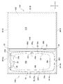
- FIG. 2 is a plan view showing the bathroom unit 100 in which the bathtub device 10 is used.
- the bathroom unit 100 mainly includes a bathtub device 10, a floor 102, an enclosure wall 104, and a partition 106.
- the bathtub apparatus 10 has a bathtub 12 as described in detail later.
- the floor 102 is provided at a position adjacent to the bathtub 12 in the short side direction Y of the tank portion 24 (described later) of the bathtub 12.
- the surrounding wall 104 is provided so as to surround the space above the bathtub 12 and the floor 102 and forms a bathroom space inside.
- the enclosure wall 104 has a bathtub-side bathroom wall portion 34-A provided so as to rise from three side edges that are separate from the edge on the floor 102 side, among the four edges of the bathtub 12.
- the surrounding wall 104 has a floor-side bathroom wall part 34-B provided so as to rise from three side edges that are separate from the bathtub 12 side among the four edges of the floor 102.
- the bathtub-side bathroom wall 34-A is provided at a position different from the floor-side bathroom wall 34-B.
- the bathtub-side bathroom wall 34-A and the floor-side bathroom wall 34-B are provided so as to rise vertically, and a boundary position 35 between them is also provided so as to extend vertically.
- the bathtub-side bathroom wall 34-A and the floor-side bathroom wall 34-B that are adjacent to each other in the short side direction Y of the tank 24 of the bathtub 12 are configured by separate members. It may be configured.
- the bathtub-side bathroom wall 34-A includes a first bathtub-side bathroom wall 34-Aa on one side in the longitudinal direction X (to be described later) of the tank 24 of the bathtub 12 and the other side in the longitudinal direction X.
- a second bathtub-side bathroom wall 34-Ab and a third bathtub-side bathroom wall 34-Ac on the opposite side of the floor 102 in the lateral direction Y (described later) of the tank 24 are included.
- a first water discharger 20 and a second water discharger 22 described later are attached to the first bathtub side bathroom wall 34-Aa.
- the bathtub-side bathroom walls 34-Aa to 34-Ac and the floor-side bathroom walls 34-B are simply referred to as “bathroom walls 34”.
- the partition 106 divides a bathroom space into a bathtub-side space 108 on the upper side of the bathtub 12 and a side-side space 110 on the side of the bathtub 12.
- the partition 106 of this embodiment has a movable wall 106a that functions as a sliding door and a fixed wall 106b, and can be opened and closed by sliding the movable wall 106a in the direction P1.
- the partition 106 allows the bather H to enter and exit between the bathtub side space 108 and the side space 110 when in the open state.
- an entrance through which the bather H enters and exits is formed at the position where the movable wall 106a is located when the partition 106 is in the open state.
- the partition 106 limits the splashing of water from the bathtub side space 108 to the side space 110 in addition to the bather H entering and exiting between the bathtub side space 108 and the side space 110. . This makes it easier to keep the side space 110 in a dry state even when bathing in the bathtub side space 108.
- the side space 110 By using the side space 110 as a dressing space, a clothes drying space, etc., the space efficiency in the residence is increased. It is done.
- the movable wall 106a is opposite to the side where the first bathtub-side bathroom wall 34-Aa to which the first water discharger 20 and the second water discharger 22 are attached is located on both sides of the tank part 24 of the bathtub 12 in the longitudinal direction X. Placed on the side.
- the fixed wall 106b is disposed on the side where the first bathtub-side bathroom wall portion 34-Aa is present, on both sides of the tank portion 24 of the bathtub 12 in the longitudinal direction X.
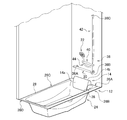
- FIG. 3 is a perspective view showing the bathtub device 10.
- FIG. 4 is a side sectional view of the bathtub apparatus 10.
- the bathtub apparatus 10 mainly includes a bathtub 12, a backrest member 14, a seat member 16, a positioning structure 18, and a plurality of water dischargers 20 and 22.
- the bathtub 12 includes a tank portion 24, flange portions 26A to 26D, and a mounting surface portion 28.
- the bathtub 12 of the present embodiment is an integrally molded product in which the mounting surface portion 28 is integrally molded together with the tank portion 24 and the flange portions 26A to 26D.
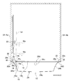
- FIG. 5 is a cross-sectional view of the bathtub device 10 as viewed from one side in the longitudinal direction X of the tank portion 24.
- the tank portion 24 has a tank shape that opens upward, and in a plan view, the horizontal first direction X and the second direction Y that are orthogonal to each other, It has a shape that is long in the first direction X and short in the second direction Y.
- the first direction X is defined as the longitudinal direction X
- the second direction Y is defined as the short direction Y, and the positional relationship of each component will be described using these.
- the tank portion 24 includes a bottom wall portion 24a and a plurality of side wall portions 24b that rise from the end portions of the four circumferences of the bottom wall portion 24a.
- An openable / closable drain plug 24c for draining overflow water is attached to the inner wall surface of the side wall 24b on one side (floor 102 side) in the lateral direction Y among the plurality of side walls 24b.
- the inner wall surface of the side wall part 24b is provided so as to be inclined toward the outer peripheral side of the tank part 24 as it goes upward.
- the flange portions 26A to 26D are provided so as to protrude outward from the upper edge portion of the tank portion 24.
- the flange portion 26 includes a rear flange portion 26A, a left flange portion 26B, a right flange portion 26C, and a front flange portion 26D.
- the rear flange portion 26A projects from a side wall portion 24b (hereinafter also referred to as a rear side wall portion 24b) on one side in the longitudinal direction X.
- the left flange portion 26B projects from the side wall portion 24b on one side (the floor 102 side) in the short direction Y
- the right flange portion 26C projects from the side wall portion 24b on the other side in the short direction Y.
- the front flange portion 26D projects from the side wall portion 24b on the opposite side of the longitudinal direction X from the rear flange portion 26A.
- the overhang dimension of the left flange portion 26B is set to be larger than the overhang dimension of the right flange portion 26C.
- each of the flange portions 26A to 26D is provided with a recess 30 whose height position decreases from the outer peripheral side toward the inner peripheral side.
- the height position here refers to a position in the vertical direction (vertical direction).
- the concave portion 30 of each flange portion 26 has an upper surface portion 30a facing upward and a step surface 30b rising from the outer peripheral edge portion of the upper surface portion 30a.
- the upper surface portion 30a and the step surface 30b of each recess 30 are provided so as to be continuous in a circumferential shape.
- a top surface portion 32 facing upward is provided on the outer peripheral side of the concave portion 30 of each flange portion 26.
- Bathtub-side bathroom wall portions 34-Aa to Ac constituting the enclosure wall 104 are placed on the top surface portion 32 of the front flange portion 26D, the right flange portion 26C, and the rear flange portion 26A.
- the step surfaces 30b of the front flange portion 26D, the right flange portion 26C, and the rear flange portion 26A extend along the vertical direction, and are provided so as to be flush with the inner wall surfaces of the bathtub-side bathroom wall portions 34-Aa to Ac.
- a partition 106 is placed on the top surface portion 32 of the left flange portion 26B.
- the step surface 30b of the left flange portion 26B is provided so as to be inclined toward the outer peripheral side of the bathtub 12 as it goes upward, and functions as a water return.
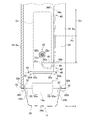
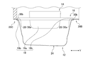
- FIG. 6 is a partial cross-sectional view of the state in which the seat member 16 is placed on the bathtub 12 as viewed from the same viewpoint as FIG.
- the upper surface portion 30a of the concave portion 30 between the left flange portion 26B and the right flange portion 26C functions as a mounting surface portion 28 on which the seat member 16 is mounted.
- the mounting surface portion 28 is provided at the inner peripheral edge portion of the left flange portion 26 ⁇ / b> B and the right flange portion 26 ⁇ / b> C of the bathtub 12, and is provided at a position facing the short direction Y of the tank portion 24.
- the mounting surface portion 28 of the present embodiment is provided in a range from the front flange portion 26D to the rear flange portion 26A of the bathtub 12 (see also FIG. 2).
- the backrest member 14 is attached to the bathtub 12 in order to provide the backrest surface 14 a inside the inner side surface of the rear side wall portion 24 b of the bathtub 12.
- the backrest member 14 is attached to the bathtub 12 using attachment means such as a hook-and-loop fastener, a magnet, and an adhesive after a part of the backrest member 14 abuts against the outer surface of the bathtub 12.
- the backrest member 14 of the present embodiment is configured using a soft material with cushioning properties.
- the backrest member 14 has a backrest surface 14 a provided at a position facing the inside of the bathtub 12.
- the backrest surface 14 a is provided so as to protrude above the upper end edge of the tank portion 24 of the bathtub 12.
- the backrest surface 14a is inclined toward the outside of the bathtub 12, and the upper end edge thereof is connected to the arc surface 14b that is convex upward.
- the backrest surface 14a has a height at which the shoulder of the bather H can be abutted when the bather H sits in the bathtub 12 in a sitting position.
- FIG. 7 is a plan view showing a state in which the seat member 16 is placed on the bathtub 12.
- the seat member 16 is a plate material having a shape that is a rectangle that is long in the lateral direction Y in plan view.
- the seat member 16 is mounted on the pair of mounting surface portions 28 of the bathtub 12 at both ends in the short direction Y.
- the seat member 16 is rigid enough to maintain its shape when the bather H sits on the seat member 16 under the state of being placed on the placing surface portion 28 of the bathtub 12.
- the seat member 16 of the present embodiment is configured using a hard material having no cushioning property, but a cushioning material having a cushioning property may be provided in a part thereof.
- the positioning structure 18 is for positioning the seat member 16 on the placing surface portion 28 of the bathtub 12.
- the positioning structure 18 includes a first positioning portion 18a that positions the seat member 16 in the longitudinal direction X, and a second positioning portion 18b that positions the seat member 16 in the lateral direction Y.
- the first positioning portion 18 a of the present embodiment is configured by the backrest surface 14 a of the backrest member 14.
- the 2nd positioning part 18b of this embodiment is comprised by the level
- Each positioning part 18a, 18b is constituted by a member different from the bathroom wall part 34.
- the first positioning portion 18a can position the seat member 16 in the longitudinal direction X by contacting the end side portion of the seat member 16 in the longitudinal direction X.
- the seat member 16 can be positioned in the longitudinal direction X by abutting against an end portion of the seat member 16 in the longitudinal direction X and in an intermediate portion in the lateral direction Y of the seat member 16.
- the second positioning portion 18b can position the seat member 16 in the lateral direction Y by contacting the end portions on both sides of the seat member 16 in the lateral direction Y.
- the seat member 16 is positioned by the positioning structure 18 so as to partially cover one side portion (left side portion in FIG. 4) of the tank portion 24 in the longitudinal direction X.
- the leg opening 24 d is provided so as to remain in the upper opening of the tank portion 24.
- a side opposite to the leg insertion opening 24d of the tank portion 24 with the seat member 16 interposed therebetween is referred to as a “back side”.
- one side in the longitudinal direction X (the left side in FIG. 4) is the “back side”.
- the second positioning portion 18b guides the movement of the seat member 16 in the longitudinal direction X by sliding the seat member 16 when the seat member 16 is placed on the placing surface portion 28 and moved in the longitudinal direction X. There is also a function to do.
- the water dischargers 20 and 22 include a first water discharger 20 and a second water discharger 22.
- the first water discharger 20 has a long columnar shape in the short direction Y as a whole, and both ends thereof are supported by individual brackets 36A and 36B.
- the brackets 36A and 36B are attached to the first bathtub-side bathroom wall 34-A on the back side of the seat member 16, and the first water discharger 20 is attached to the first bathtub-side bathroom wall 34-A in the bracket 36A. , 36B.
- a plurality of discharge ports 20 a for discharging water are formed on the outer surface of the first water discharger 20.
- the plurality of discharge ports 20a are arranged in a row in the lateral direction Y.
- shower-like water Wb is discharged from the plurality of discharge ports 20a toward the front side of the first bathtub-side bathroom wall 34-A (also in FIG. 4). reference).
- This shower-like water is discharged so as to pass through a wide and flat area in the lateral direction Y.
- the first water discharger 20 is supported to be rotatable about an axis Ax extending in the short direction Y with respect to the bracket 36, and the discharge angle can be adjusted by the rotation.
- the second water discharger 22 is a shower head used for the shower device 38.
- the shower device 38 includes a second water discharger 22, a shower hook 40, a slide bar 42, and a shower hose 44 (see also FIG. 3).
- the second water discharger 22 is connected to the tip of the shower hose 44.
- the 2nd water discharging tool 22 has the axial part 22a inserted in the holding hole 40a (after-mentioned) of the shower hook 40, and the head part 22b provided in the front-end
- a plurality of discharge ports 22c are formed in the head portion 22b.
- the plurality of discharge ports 22c are arranged so as to be concentrically arranged.
- the second water discharger 22 When water is supplied through a shower hose 44 from a water supply channel, which will be described later, the second water discharger 22 has shower-like water Wb from the plurality of discharge ports 22c toward the front side of the first bathtub-side bathroom wall 34-A. (See also FIG. 4).
- the shower hook 40 has a holding hole 40a for detachably holding the shaft portion 22a of the second water discharger 22, and a through hole 40b through which the slide bar 42 is inserted.
- the shower hook 40 has a column shape extending in one direction, and the holding hole 40a and the through hole 40b are provided at one end and the other end of the shower hook 40, respectively.
- the second water discharger 22 is held in a relative position with respect to the bathtub 12 when the shaft portion 22a is inserted into the holding hole 40a of the shower hook 40.
- the slide bar 42 is attached to the first bathtub-side bathroom wall 34-A, and the second water discharger 22 is attached to the first bathtub-side bathroom wall 34 via the shower hook 40 and the slide bar 42.
- the shower hook 40 can slide up and down along the slide bar 42.
- the shower hook 40 is held at an arbitrary position by friction or the like within a slidable range with respect to the slide bar 42. Thereby, the 2nd water discharging tool 22 can adjust and hold
- the shower hook 40 is rotatable around the central axis of the slide bar 42. Thereby, the relative position in the horizontal surface of the 2nd water discharging tool 22 with respect to the bathtub 12 can be adjusted and hold
- the shaft part 22a of the second water discharger 22 is inserted into the holding hole 40a of the shower hook 40 so as to be rotatable around its own shaft part 22a.
- the shower hook 40 has an angle adjustment mechanism (not shown) that adjusts and holds the angle formed by the shaft portion 22a of the second water discharger 22 with respect to the vertical line.
- the 2nd water discharging tool 22 can adjust and hold
- a water supply path (not shown) for supplying water to the discharge port of the first water discharger 20 and the discharge port of the second water discharger 22 is formed inside the first water discharger 20, the slide bar 42, and each bracket 36.
- a hot water / water mixing valve (not shown) for adjusting the mixing ratio between the cold water supplied from the upstream cold water supply passage and the hot water supplied from the upstream hot water supply passage is installed in the water supply passage.
- the hot / cold water mixing ratio of the hot / cold water mixing valve is operated by the first handle 46 attached to the bracket 36 on one side (left side in the figure) in the short direction Y with respect to the first water discharger 20.
- a switching valve for switching the water supply destination of the water supply channel is installed downstream of the hot water / water mixing valve.
- the switching valve is operated by a second handle 48 attached to the bracket 36 on the other side (right side in the drawing) in the short direction Y with respect to the first water discharger 20.
- the water supply destination of this water supply channel can be switched to one or both of the discharge port of the first water discharger 20 and the discharge port of the second water discharger 22 by operating the second handle 48.
- the water supply destination of the water supply channel is switched to either the discharge port of the first water discharger 20 or the discharge port of the second water discharger 22, the discharge port of the first water discharger 20 or the second water discharge destination Water is discharged from either one of the outlets of the two water dischargers 22.
- the plurality of water dischargers 20 and 22 can individually switch the presence or absence of the discharge operation.
- the first water discharger 20 and the second water discharger 22 are located behind the seat member 16 from the contact position Pa between the first positioning portion 18 a of the positioning structure 18 and the seat member 16 (in the drawing). It is arranged at a position offset to the left). This is because the first water discharger 20 and the second water discharger 22 are set to the reference line La when a line extending vertically through the contact position between the first positioning portion 18a of the positioning structure 18 and the seat member 16 is defined as the reference line La. It means that it is arranged on the back side of the seat member 16.
- the bather H can use the bathtub device 10 in the following manner.
- First mode of use Used in a sitting position where the bather H sits down in the bathtub 12.
- Second usage mode Used in a standing posture where the bather H stands on the bathtub 12.
- Third mode of use Used in a sitting position in which a seat member 16 placed on the bathtub 12 is seated.
- FIG. 8 is a diagram showing a usage example in the first usage mode.
- the bather H takes a sitting posture with his / her waist in the bathtub 12 and protruding both legs.
- the bather H places his / her back on the rear side wall portion 24b of the bathtub 12 and puts his / her back on the backrest surface 14a of the backrest member 14.
- this sitting posture it can be used while warming the waist and lower body with warm water Wa stored in the bathtub 12.
- the water Wb discharged from the first water discharger 20 or the water Wb discharged from the second water discharger 22 may be used.
- FIG. 9 is a diagram showing a usage example in the second usage mode.
- the second water discharger 22 is used as an overhead shower.
- the relative position of the second water discharger 22 with respect to the bathtub 12 is adjusted in the vertical direction so that the second water discharger 22 is arranged at a position higher than the head of the bather H in a standing posture.
- the discharge direction and the discharge angle of the second water discharger 22 are adjusted so that water is discharged from the second water discharger 22 toward the bather H.
- FIG. 1 is also a diagram showing a usage example when in the third usage mode.
- the seat member 16 When in the third usage mode, the seat member 16 partially covers one side portion of the tank portion 24 from above so that the leg insertion opening 24d remains in the upper opening of the tank portion 24.
- the seat member 16 covers the tank part 24 of the bathtub 12 from the upper side, it can be said that the dimension and shape are set so that such a leg insertion opening 24d is formed in the upper opening part of the tank part 242. .
- the bather H can take the sitting posture which sits on the seat member 16 in the state which put a part of his both legs into the bathtub 12 from the leg insertion opening 24d.
- the seat member 16 on the placing surface portion 28 of the bathtub 12 is positioned in the longitudinal direction X and the lateral direction Y by the positioning structure 18. Specifically, the seat member 16 has a longitudinal direction so that displacement of the seat member 16 toward the back side (side approaching the water dischargers 20 and 22) is restricted by contact with the first positioning portion 18 a of the backrest member 14. Positioned at X. Further, the seat member 16 is positioned in the short direction Y so that the displacement in the short direction Y is regulated by the contact with the second positioning portion 18b of the bathtub 12.
- the first water discharger 20 can discharge water so as to hit the waist of the bather H when the bather H sits on the seat member 16 positioned by the positioning structure 18. In satisfying this condition, the discharge angle of the first water discharger 20 may be adjusted.
- the second water discharger 22 can discharge water so as to hit the shoulder of the bather H. In satisfying this condition, the relative position, the discharge direction, and the discharge angle of the second water discharger 22 with respect to the bathtub 12 may be adjusted.
- the second water discharger 22 can discharge water so as to hit the bather H at a position higher than the water application position by the first water discharger 20. In other words, the second water discharger 22 can discharge water so as to hit the bather H at a position different from the water application position by the first water discharger 20 in the vertical direction.
- the first water discharger 20 is on the first bathtub side on the back side of the seat member 16 so as to pass through a wide range in the waist width direction (short direction Y) from the waist portion of the bather H in a sitting position on the seat member 16. Water is discharged toward the front side of the bathroom wall 34-A.
- the second water discharger 22 is shorter than the passage range of water discharged from the first water discharger 20 when the discharge direction of the second water discharger 22 is aligned with the normal direction of the first bathtub-side bathroom wall 34-A. Water is discharged so as to pass through a narrow area in the direction Y.
- the first water discharger 20 and the second water discharger 22 have different water discharge modes so that the discharged water passes through different ranges.
- the number, position, etc. of the discharge ports of the first water discharger 20 and the second water discharger 22 are set so as to satisfy such conditions.
- the first water discharger 20 and the second water discharger 22 can discharge water so as to hit the bather H sitting on the seat member 16 positioned by the positioning structure 18.
- the bather H bathes the water discharged from the water dischargers 20 and 22 while putting a part of both legs into the water stored in the bathtub 12. Therefore, the bather H can warm his feet and upper body in the sitting position while suppressing the burden on the heart and lungs by not soaking the upper body of the bather H in the water in the bathtub 12, and a high relaxing effect can be obtained.
- FIG. 10 is a diagram showing another usage mode when in the third usage mode.
- the 2nd water discharging tool 22 is detachable with respect to the shower hook 40 as another member holding the relative position with respect to the bathtub 12.
- FIG. Therefore, when the bather H is in a sitting position on the seat member 16, the second water spouting device 22 is removed from the shower hook 40 and the bather H holds it in his hand, and the second water spout is placed at a place desired by the bather H. Water Wb discharged from the tool 22 is bathed. Thereby, bather H can bathe in a favorite part of bather H, taking a foot bath in the sitting position, and a higher relaxation effect can be obtained.
- the bathtub apparatus 10 of this embodiment is demonstrated.
- the bathtub apparatus 10 when the bather H is in a sitting position sitting on the seat member 16, the water discharged from the water dischargers 20 and 22 can be bathed while putting a leg into the water in the bathtub 12. Therefore, the bather H can bathe while taking a foot bath while sitting on the seat member 16, and the bathtub apparatus 10 suitable for realizing a new mode of bathing can be obtained.
- the bathtub apparatus 10 includes a positioning structure 18 for positioning the seat member 16 by contact with the seat member 16. Therefore, when the bather H is in the sitting posture on the seat member 16, the positional deviation of the seat member 16 with respect to the bathtub 12 can be restricted by contact with the positioning structure 18, and the sitting posture can be easily maintained stably.
- the relative positions of the first water discharger 20 and the second water discharger 22 with respect to the bathtub 12 are held by other members (the bracket 36 and the shower hook 40). Therefore, when the bather H is in the sitting position on the seat member 16, the water discharged from the water dischargers 20, 22 can be bathed with both hands left free, and a higher relaxing effect can be easily obtained.
- the first water discharger 20 and the second water discharger 22 are disposed at a position offset from the contact position between the first positioning portion 18a of the positioning structure 18 and the seat member 16 to the back side of the seat member 16. Therefore, when the bather H sits on the seat member 16 in a state facing the back side in the longitudinal direction X, each water discharger 20 is located at a position away from the bather H on the back side in the longitudinal direction X. 22 is arrange
- the second water discharger 22 capable of adjusting the relative position and discharge angle with respect to the bathtub 12 is seated from the above-described contact position Pa in at least a part of the adjustable range. What is necessary is just to be arrange
- the water dischargers 20 and 22 include a plurality of water dischargers 20 and 22 capable of simultaneously discharging water. Therefore, when the bather H is in a sitting position on the seat member 16, by discharging water simultaneously from the plurality of water dischargers 20, 22, it becomes easy to bathe a lot of water in a wide range of the body of the bather H, which is high. It becomes easier to get a relaxing effect.
- the water dischargers 20 and 22 include a plurality of water dischargers 20 and 22 that can discharge water so as to hit the bather H at different positions in the vertical direction. Therefore, when the bather H is in a sitting position on the seat member 16, a bathing position can be selected from a plurality of places to a favorite position, and the usability for the bather H to bathe in the sitting position is improved.
- the second water discharger 22 can be held by adjusting the relative position with respect to the bathtub 12. Therefore, the discharge position of the 2nd water discharging tool 22 can be adjusted according to the liking of the bather H, and the usability when the bather H bathes in the sitting position on the seat member 16 becomes favorable.
- the 2nd water discharging tool 22 can adjust and hold
- the second water discharger 22 can adjust the relative position with respect to the bathtub 12 so as to be disposed at a position overlapping the center line Lc in the short direction Y of the tank portion 24 in a plan view.
- the center line Lc in the short direction Y of the tank 24 is a position Pb (in the short direction Y) that bisects the maximum inner width dimension Sa in the short direction Y of the tank 24 in plan view.
- the 2nd water discharging tool 22 When the 2nd water discharging tool 22 is arrange
- the second water discharger 22 can be disposed on the back side of the member 16.
- the bather H When water is discharged from the second water discharger 22 under this positional relationship, the bather H can easily bathe in a wide range in the left-right direction. Therefore, it becomes easy to obtain a high relaxing effect by bathing in a wide range of the body of the bather H, while improving usability by adjusting the discharge position of the second water discharger 22.
- the slide bar 42 is attached to the first bathtub-side bathroom wall portion 34-A on one side of the tank portion 24 in the longitudinal direction X.
- the slide bar 42 is disposed at a position offset in the short direction Y with respect to the center line Lc in the short direction Y of the tank portion 24.
- the slide bar 42 is disposed at a position that does not overlap the center line Lc of the tank portion 24 in plan view.
- the offset amount which is the amount by which the slide bar 42 is offset in the lateral direction Y from the center line Lc of the tank portion 24, is a standard dimension obtained by dividing the maximum inner width dimension Sa of the tank portion 24 into four equal parts. When Sb is set, it is set to be larger than the reference dimension Sb.
- the first bathtub side bathroom wall 34-A includes an interior material such as a steel plate and a structural surface material such as a gypsum board lined on the back surface of the interior material.
- the slide bar 42 is fastened to the first bathtub-side bathroom wall 34-A using a fastener, the slide bar 42 is placed at a position where the fastener can be fastened to the structural face material of the first bathtub-side bathroom wall 34-A. Be placed.
- the slide bar 42 is disposed at a position offset in the short direction Y with respect to the center line Lc in the short direction Y of the tank portion 24. Therefore, as described with reference to FIG. 8, there is an advantage that the head of the bather H does not easily hit the slide bar 42 when sitting in the bathtub 12 and sitting down with both legs protruding. Further, in plan view, a space Sc (see FIG. 5) for installing other components on the inner side surface of the first bathtub-side bathroom wall 34-A can be secured in the vicinity of the center line Lc of the tank portion 24. By installing mirrors and shelves in the space Sc, there is an advantage that it is easy to wash the body in the bathtub 12.
- the bathtub device 10 of this embodiment is also characterized by the shower device 38.
- the shower device 38 includes a second water discharger 22 (shower head), a shower hook 40, a slide bar 42, and a shower hose 44.
- the details of the second water discharger 22 and the shower hook 40 are as described above.
- the slide bar 42 has a bar shape that supports the shower hook 40 so as to be slidable in the vertical direction, and an upper portion and a lower portion thereof are supported by the brackets 36B and 36C.
- the brackets 36B and 36C include a lower bracket 36B that supports the lower portion of the slide bar 42 and an upper bracket 36C that supports the upper portion of the slide bar 42.
- the lower bracket 36 ⁇ / b> B is also a bracket that supports the first water discharger 20.
- the lower bracket 36B and the upper bracket 36C are in contact with the shower hook 40, thereby determining a slidable range Sd of the shower hook 40 with respect to the slide bar 42.
- the lower bracket 36 ⁇ / b> B is in contact with the shower hook 40 to determine the lower limit position of the slidable range Sd of the shower hook 40.
- the upper bracket 36 ⁇ / b> C abuts on the shower hook 40 to determine the upper limit position of the slidable range Sd of the shower hook 40.
- the shower hose 44 is for supplying water to the second water discharger 22, and has flexibility.
- the shower hose 44 is drawn from the upper bracket 36 ⁇ / b> C, and is supplied with water through the aforementioned water supply path formed inside the upper bracket 36 and the slide bar 42.
- the shower hose 44 has a base end portion 44a disposed at a position higher than the center position Pc in the vertical direction of the slidable range Sd of the shower hook 40.
- a base end portion 44 a is disposed at a height position equivalent to the upper limit position of the slidable range Sd of the shower hook 40.
- the base end portion 44a of the shower hose 44 is arranged at a position higher than the center position Pc of the slidable range Sd of the shower hook 40. Therefore, when the shower hook 40 is brought close to the lower limit position of the slidable range Sd, the intermediate part of the shower hose 44 is difficult to be immersed in the bathtub water in the bathtub 12. From the psychological and hygienic aspects of the bather H, it is preferable to avoid soaking articles in the bath water. For this reason, according to this embodiment, generation
- the base end portion 44a of the shower hose 44 may be arranged at a height position equal to or higher than the upper limit position of the slidable range Sd of the shower hook 40. “Equivalent” in this specification includes both the case where the comparison targets are the same and the case where they are almost the same.
- FIG. 11 is a figure showing an example of use of bathtub apparatus 10 of a 2nd embodiment.
- the bathtub device 10 of the second embodiment is different from the first embodiment in that the third water discharger 50 is included in the water discharger 20, 22, 50.
- the third water discharger 50 is a shower head disposed at a higher position than the second water discharger 22.
- a relay pipe 52 extending from the upper end portion of the slide bar 42 is connected to the third water discharger 50.
- a part of a water supply path for supplying water to the first water discharger 20 and the second water discharger 22 is branched and formed inside the relay pipe 52, and water is supplied to the third water discharger 50 through the water supply path.
- the third water discharger 50 is switched between presence and absence of a discharge operation.
- the third water discharger 50 is used as an overhead shower that discharges the shower-like water Wb when the bather H is standing on the bathtub 12 as described above. Further, when the bather H is in a sitting position on the seat member 16, the bather H may be used in combination with the first water discharger 20 or the second water discharger 22 as shown in FIG. 11. In this case, the third water discharger 50 may also be configured to discharge water simultaneously with the first water discharger 20 and the second water discharger 22.
- FIG. 12 is a diagram illustrating the bathtub apparatus 10 according to the third embodiment.
- the bathtub device 10 of the third embodiment is different from the first embodiment in that a shower head 56 is embedded in the ceiling 54 of the bathroom. Water is supplied to the shower head 56 through a water supply channel (not shown).
- the shower head 56 is used as an overhead shower that discharges shower-like water Wb toward the head of the bather H when the bather H is standing on the bathtub 12.
- the shower head 56 receives an operation on a handle (not shown), and the presence / absence of the discharge operation is switched.
- the mounting surface part 28 of the bathtub 12 demonstrated the example provided in the position facing the transversal direction Y of the bathtub 12, the position in particular is not restricted. For example, it may be provided at a position facing the longitudinal direction X of the bathtub 12.
- the mounting surface part 28 of the bathtub 12 demonstrated the example provided in the inner peripheral part of the flange part 26, you may be provided in an outer peripheral side part from the inner peripheral part of the flange part 26, and the middle of the up-down direction of the tank part 24 may be provided. It may be provided at a position.
- the positioning structure 18 only needs to be able to position the seat member 16 in at least one of the longitudinal direction X and the short direction Y of the tank portion 24.
- the positioning structure 18 of the embodiment has been described with respect to the example in which the seat member 16 is positioned in the longitudinal direction X by abutting against one end side of the seat member 16 in the longitudinal direction X.
- the positioning structure 18 may position the seat member 16 in the lateral direction Y by abutting against one end of the seat member 16 in the lateral direction Y.
- the water dischargers 20 and 22 may be disposed at a position offset to one side in the lateral direction Y from the contact position between the positioning structure 18 and the seat member 16.
- the positioning structure 18 is brought into contact with the end portion on one side of the seat member 16 in the first direction.
- the seat member 16 may be positioned, and the water dischargers 20 and 22 may be disposed at a position offset to one side in the first direction from the contact position between the positioning structure 18 and the seat member 16.
- the seat member 16 covers one side part of the tank part 24 in the first direction so that the leg insertion opening 24d remains in the upper opening of the tank part 24.
- the water dischargers 20 and 22 are also arranged on the opposite side of the first direction with respect to the leg insertion opening 24d across the seat member 16 positioned by the positioning structure 18.
- the positioning structure 18 of the embodiment the example in which the backrest surface 14a of the backrest member 14 is the first positioning portion 18a has been described, but is not limited thereto.
- a convex portion protruding upward may be provided on the flange portion 26 of the bathtub 12, and the convex portion may be used as the first positioning portion.
- the seat member 16 is positioned by contact between the end side portion of the seat member 16 and the convex portion.
- the positioning structure 18 may be configured by any one of the bathtub-side bathroom walls 34-Aa to 34-Ac.
- the first bathtub-side bathroom wall portion 34-Aa may be the first positioning portion 18a
- the third bathtub-side bathroom wall portion 34-Ab may be the second positioning portion 18b
- the positioning structure 18 includes, for example, a first fitting portion provided on the flange portion 26 of the bathtub 12 and the like, and a first fitting portion provided on the lower surface of the seat member 16 and fitted with the first fitting portion. 2 fitting parts may be provided.
- the first fitting portion is a convex portion or a concave portion
- the second fitting portion is a concave portion or a convex portion that fits with the first fitting portion.
- the seat member 16 is positioned in both the longitudinal direction X and the lateral direction Y by fitting the first fitting portion of the bathtub 12 and the second fitting portion of the seat member 16.
- the bathtub apparatus 10 demonstrated the example provided with the some water discharging tool 20,22, it should just have at least 1 water discharging tool 20,22.
- only one of the first water discharger 20 and the second water discharger 22 of the first embodiment may be provided, or only the third water discharger 50 of the second embodiment may be provided.
- the water dischargers 20 and 22 have been described by taking an example of discharging shower-like water from a plurality of discharge ports, the present invention is not limited thereto.
- the water dischargers 20 and 22 may discharge membrane-like or columnar rectified water from the discharge port.
- the water dischargers 20 and 22 may be held by other members (the bracket 36 and the shower hook 40).
- the other members are not particularly limited, and include the bathroom wall 34, the bathtub 12, and the like.
- the water discharging tools 20 and 22 demonstrated the example attached to the 1st bathtub side bathroom wall part 34-Aa in the back side of the seat member 16, it is not restricted to this,
- the bathtub 12 in the back side of the seat member 16 It may be attached to the rear flange portion 26A.
- the water dischargers 20 and 22 may be attached not to the back side of the seat member 16 but to the third bathtub-side bathroom wall 34-Ac on the side of the seat member 16 or the right flange portion 26C of the bathtub 12. Good. That is, the water dischargers 20 and 22 may be attached to the bathtub-side bathroom walls 34-Aa to Ac or the bathtub 12 directly or via other members.
- the water dischargers 20 and 22 are not attached to the floor bathroom wall 34-B directly or via other members. In any of these cases, the water dischargers 20 and 22 are not disposed above the floor 102 at a position adjacent to the bathtub 12 but are disposed entirely above the bathtub 12. From another point of view, all of the discharge ports of the water dischargers 20 and 22 are arranged above the bathtub 12.
- the backrest member 14 does not need to be. Moreover, although the backrest member 14 demonstrated the example comprised using the soft material with a cushioning property, you may provide the hard material without a cushioning property in the part. Moreover, the backrest member 14 may be comprised using the hard raw material without cushioning property, and may provide the soft raw material with cushioning property in the one part.
- the base end portion 44 a of the shower hose 44 may be disposed at a position higher than the center position Pc of the slidable range Sd of the shower hook 40, and the pull-out position of the shower hose 44 is limited to the upper bracket 36. Absent.
- the drawer position of the shower hose 44 may be the slide bar 42 or the bathroom wall 34 in addition to the upper bracket 36.
- the partition 106 of the present embodiment has been described as having the movable wall 106a functioning as a sliding door and the fixed wall 106b, the type and number of the walls are not limited thereto.
- another movable wall may be used as an alternative to the fixed wall 106b.
- the movable wall may function as a hinged door or the like.
- the water discharger may be attached to a bathtub-side bathroom wall or the bathtub rising from an end side of the bathtub.
- the bathtub apparatus is the first aspect or the second aspect, in which the positioning structure is the first of the seat member when one of the longitudinal direction and the short direction of the tank portion is the first direction. It has a positioning part which can position the seat member by coming into contact with an edge part in one direction, and the water discharger is on one side in the first direction from the contact position between the positioning part and the seat member. It may be arranged at a position offset in According to this aspect, when the bather sits on the seat member in a state facing the one side in the first direction, the water discharger is arranged at a position away from the bather on the one side in the first direction. It becomes easy to suppress interference between the bather and the water discharger. For this reason, without taking care of interference with the water discharger, the bather can take a bath while taking a foot bath while sitting deeply on the seat member, and can easily obtain a high relaxing effect.
- the bathtub apparatus of the fourth aspect may include a plurality of water dischargers capable of simultaneously discharging water. According to this aspect, when the bather is in the sitting position on the seat member, it becomes easy to bathe a lot of water in a wide range of the bather's body, and it becomes easier to obtain a high relaxing effect.
- the bathtub apparatus of the fifth aspect includes a plurality of water dischargers capable of discharging water so as to hit the bather at different positions in the vertical direction. Also good. According to this aspect, when the bather is in the sitting position on the seat member, the bathing position can be selected from a plurality of locations to a desired location, and the convenience for the bather to bathe in the sitting posture is improved.
- the bathtub device of the sixth aspect may be capable of holding the water discharger by adjusting a relative position with respect to the bathtub. According to this aspect, the discharge position of the water discharger can be adjusted according to the preference of the bather, and the convenience for the bather to bathe in a sitting position on the seat member is improved.
- the bathtub apparatus of the seventh aspect may be capable of adjusting the relative position with respect to the bathtub in the vertical direction in the sixth aspect.
- the discharge position of the water discharger can be adjusted in the vertical direction so as to be arranged at a position suitable for applying water to the shoulder or head of the bather.
- the bathtub device is the sixth aspect or the seventh aspect, wherein the seat member is positioned by the positioning structure so as to partially cover one side portion of the tank portion in the longitudinal direction, and the water discharge tool is
- the bathtub is disposed on one side in the longitudinal direction with respect to the seat member positioned by the positioning structure, and is disposed at a position overlapping the center line in the short direction of the tank portion.
- the relative position with respect to may be adjustable. According to this aspect, it is easy to bathe in a wide range of the bather in the left-right direction only by finely adjusting the seat position of the bather's seat member while adjusting the relative position of the water discharger with respect to the bathtub. Therefore, it becomes easy to obtain a high relaxing effect by bathing in a wide area of the bather's body while improving usability by adjusting the discharge position of the water discharger.
- the present invention relates to a bathtub device used in a bathroom.
Landscapes
- Health & Medical Sciences (AREA)
- Public Health (AREA)
- Epidemiology (AREA)
- General Health & Medical Sciences (AREA)
- Bathtubs, Showers, And Their Attachments (AREA)
- Bathtub Accessories (AREA)
- Domestic Plumbing Installations (AREA)
Abstract
槽部24を上側から部分的に覆う座部材16を載せるための載せ面部28を有する浴槽12と、載せ面部28上の座部材16を位置決めするための位置決め構造18と、位置決め構造18により位置決めされた座部材16上に座る入浴者Hに当たるように水Wbを吐き出し可能な吐水具20、22とを備える。これにより、入浴者Hが座部材16上に座位姿勢にあるとき、浴槽12内の水Waに脚を入れつつ、吐水具20、22から吐き出された水Wbを浴びられる。
Description
本発明は、浴室に用いられる浴槽装置に関する。
従来より、浴室に用いられる浴槽装置として、様々な水浴びを実現できるものが提案されている。この種の浴槽装置として、特許文献1には、浴槽に載せられる風呂蓋を座椅子として使用し、シャワーヘッドから吐き出される水を座位姿勢のまま浴びられるようにしたものが提案されている。
浴室用設備の事業者は、種々の態様の水浴びを実現できる浴槽装置を提供することにより、市場の拡大を目指している。本発明者は、更なる市場の拡大を展開するうえで、新しい水浴びの態様の必要性を感じ、本発明を想到するに到った。
本発明は、このような課題に鑑みてなされ、その目的は、新しい態様の水浴びを実現するのに適した浴槽装置を提供することにある。
上記の課題を解決するための本発明の第1の態様は浴槽装置である。第1態様の浴槽装置は、槽部を上側から部分的に覆う座部材を載せるための載せ面部を有する浴槽と、前記載せ面部上の前記座部材を位置決めするための位置決め構造と、前記位置決め構造により位置決めされた前記座部材上に座る入浴者に当たるように水を吐き出し可能な吐水具と、を備える。ここでの入浴者とは浴槽装置の使用国での平均体格をもつ成人をいう。
第1態様の浴槽装置によれば、入浴者が座部材上に座位姿勢にあるとき、浴槽内の水に脚を入れつつ、吐水具から吐き出された水を浴びられる。よって、新しい態様の水浴びを実現するのに適した浴槽装置を得られる。
以下、実施形態、変形例では、同一の構成要素に同一の符号を付し、重複する説明を省略する。また、各図面では、説明の便宜のため、構成要素の一部を適宜省略したり、構成要素の寸法を適宜拡大、縮小して示す。
[第1実施形態]
図1は、第1実施形態の浴槽装置10の使用例を示す図である。浴槽装置10は、浴槽12上に載せた座部材16上に入浴者Hが座った座位姿勢のまま、浴槽12内に溜めた水Waに脚の一部を入れつつ、吐水具20、22から吐き出された水Wbを入浴者Hが浴びることで用いられる。
図1は、第1実施形態の浴槽装置10の使用例を示す図である。浴槽装置10は、浴槽12上に載せた座部材16上に入浴者Hが座った座位姿勢のまま、浴槽12内に溜めた水Waに脚の一部を入れつつ、吐水具20、22から吐き出された水Wbを入浴者Hが浴びることで用いられる。
図2は、浴槽装置10が用いられる浴室ユニット100を示す平面図である。浴室ユニット100は、主に、浴槽装置10と、床102と、囲い壁104と、間仕切り106とを備える。
浴槽装置10は、詳細は後述するが、浴槽12を有する。床102は、浴槽12に対して、浴槽12の槽部24(後述する)の短辺方向Yに隣り合う位置に設けられる。囲い壁104は、浴槽12及び床102の上方の空間を取り囲むように設けられ、浴室空間を内部に形成する。囲い壁104は、浴槽12の四周の端辺部のうち、床102側の端辺部とは別にある三方の端辺部から立ち上がるように設けられる浴槽側浴室壁部34-Aを有する。また、囲い壁104は、床102の四周の端辺部のうち、浴槽12側とは別にある三方の端辺部から立ち上がるように設けられる床側浴室壁部34-Bを有する。浴槽側浴室壁部34-Aは、床側浴室壁部34-Bとは別の位置に設けられることになる。浴槽側浴室壁部34-Aと床側浴室壁部34-Bとは鉛直に立ち上がるように設けられ、これらの間の境界位置35も鉛直に延びるように設けられる。本実施形態では、浴槽12の槽部24の短辺方向Yに隣り合う浴槽側浴室壁部34-Aと床側浴室壁部34ーBとは、別部材により構成されるが、同部材により構成されてもよい。
浴槽側浴室壁部34-Aには、浴槽12の槽部24の長手方向X(後述する)の一方側にある第1浴槽側浴室壁部34-Aaと、その長手方向Xの他方側にある第2浴槽側浴室壁部34-Abと、その槽部24の短手方向Y(後述する)の床102とは反対側にある第3浴槽側浴室壁部34-Acとが含まれる。第1浴槽側浴室壁部34-Aaには後述する第1吐水具20や第2吐水具22が取り付けられる。以下、浴槽側浴室壁部34-Aa~34-Acや床側浴室壁部34-Bを総称するときは単に「浴室壁部34」という。
間仕切り106は、浴槽12の上側の浴槽側空間108と、浴槽12の脇側の脇側空間110とに浴室空間を区画する。本実施形態の間仕切り106は、引き戸として機能する可動壁106aと、固定壁106bとを有し、可動壁106aを方向P1にスライドさせることで開閉可能である。間仕切り106は、開状態にあるとき、浴槽側空間108と脇側空間110との間での入浴者Hの出入りを許容する。間仕切り106が閉状態にあるときに可動壁106aがある位置には、間仕切り106が開状態にあるとき、入浴者Hが出入りする出入口が形成される。間仕切り106は、閉状態にあるとき、浴槽側空間108と脇側空間110との間での入浴者Hの出入りの他に、浴槽側空間108から脇側空間110への水の飛び散りを制限する。これにより、浴槽側空間108内で水浴びするときでも脇側空間110をドライな状態に保ち易くなり、脇側空間110を脱衣空間や物干し空間等として利用することで、住居内の空間効率を高められる。
可動壁106aは、浴槽12の槽部24の長手方向Xの両側のうち、第1吐水具20や第2吐水具22が取り付けられる第1浴槽側浴室壁部34-Aaがある側とは反対側に配置される。固定壁106bは、浴槽12の槽部24の長手方向Xの両側のうち、第1浴槽側浴室壁部34-Aaがある側に配置される。これにより、間仕切り106が開状態にあるとき、各吐水具20、22が取り付けられる第1浴槽側浴室壁部34-Aaから長手方向Xに離れた位置に、入浴者Hが出入りするための出入口が形成される。よって、入浴者Hが出入口を通して出入りするとき、各吐水具20、22との干渉を抑えられる。
図3は、浴槽装置10を示す斜視図である。図4は、浴槽装置10の側面断面図である。浴槽装置10は、主に、浴槽12と、背もたれ部材14と、座部材16と、位置決め構造18と、複数の吐水具20、22とを備える。
(浴槽)
図3に示すように、浴槽12は、槽部24と、フランジ部26A~26Dと、載せ面部28とを有する。本実施形態の浴槽12は、槽部24及びフランジ部26A~26Dとともに載せ面部28が一体成形された一体成形品である。
図3に示すように、浴槽12は、槽部24と、フランジ部26A~26Dと、載せ面部28とを有する。本実施形態の浴槽12は、槽部24及びフランジ部26A~26Dとともに載せ面部28が一体成形された一体成形品である。
図5は、浴槽装置10を槽部24の長手方向Xの一方側から見た断面図である。図2、図4、図5に示すように、槽部24は、上方に向けて開いた槽状をなし、平面視において、互いに直交する水平な第1方向X及び第2方向Yのうち、第1方向Xに長く第2方向Yに短い長方形を呈する形状をもつ。以下、第1方向Xを長手方向X、第2方向Yを短手方向Yとし、これらを用いて各構成要素の位置関係を説明する。槽部24は、底壁部24aと、底壁部24aの四周の端辺部から立ち上がる複数の側壁部24bとを有する。複数の側壁部24bのうち、短手方向Yの一方側(床102側)にある側壁部24bの内壁面には、オーバーフロー水を排水するための開閉可能な排水栓24cが取り付けられる。側壁部24bの内壁面は、上方に向かうにつれて、槽部24の外周側に向かって傾くように設けられる。
フランジ部26A~26Dは、槽部24の上縁部から外側に張り出すように設けられる。フランジ部26は、後フランジ部26Aと、左フランジ部26Bと、右フランジ部26Cと、前フランジ部26Dとを含む。後フランジ部26Aは、長手方向Xの一方側にある側壁部24b(以下、後側壁部24bともいう)から張り出す。左フランジ部26Bは短手方向Yの一方側(床102側)にある側壁部24bから張り出し、右フランジ部26Cは短手方向Yの他方側にある側壁部24bから張り出す。前フランジ部26Dは、後フランジ部26Aとは長手方向Xの反対側にある側壁部24bから張り出す。左フランジ部26Bの張り出し寸法は右フランジ部26Cの張り出し寸法より大きくなるように設定される。
図4、図5に示すように、各フランジ部26A~26Dの内周縁部には外周側から内周側に向かって高さ位置が低くなる凹部30が設けられる。ここでの高さ位置とは上下方向(鉛直方向)での位置をいう。各フランジ部26の凹部30は、上方に臨む上面部30aと、上面部30aの外周縁部から立ち上がる段差面30bとを有する。各凹部30の上面部30aや段差面30bは周状に連なるように設けられる。
各フランジ部26の凹部30より外周側には上方に臨む天面部32が設けられる。前フランジ部26D、右フランジ部26C及び後フランジ部26Aの天面部32には囲い壁104を構成する浴槽側浴室壁部34-Aa~Acが載せられる。前フランジ部26D、右フランジ部26C及び後フランジ部26Aの段差面30bは鉛直方向に沿って延びるとともに、浴槽側浴室壁部34-Aa~Acの内壁面と面一となるように設けられる。左フランジ部26Bの天面部32には間仕切り106が載せられる。左フランジ部26Bの段差面30bは、上方に向かうにつれて、浴槽12の外周側に向けて傾くように設けられ、水返しとして機能する。
図6は、浴槽12に座部材16を載せた状態を図5と同じ視点から見た部分断面図である。左フランジ部26Bと右フランジ部26Cとの凹部30の上面部30aは座部材16を載せるための載せ面部28として機能する。載せ面部28は、浴槽12の左フランジ部26Bと右フランジ部26Cとの内周縁部に設けられており、槽部24の短手方向Yに対向する位置に設けられることになる。本実施形態の載せ面部28は浴槽12の前フランジ部26Dから後フランジ部26Aまでの範囲に設けられる(図2も参照)。
(背もたれ部材)
図3、図4に示すように、背もたれ部材14は、浴槽12の後側壁部24bの内側面より内側に背もたれ面14aを設けるため、浴槽12に取り付けられる。背もたれ部材14は、浴槽12の外面に一部を突き当てたうえで、面ファスナー、磁石、接着等の取付手段を用いて、浴槽12に取り付けられる。本実施形態の背もたれ部材14はクッション性のある軟質素材を用いて構成される。
図3、図4に示すように、背もたれ部材14は、浴槽12の後側壁部24bの内側面より内側に背もたれ面14aを設けるため、浴槽12に取り付けられる。背もたれ部材14は、浴槽12の外面に一部を突き当てたうえで、面ファスナー、磁石、接着等の取付手段を用いて、浴槽12に取り付けられる。本実施形態の背もたれ部材14はクッション性のある軟質素材を用いて構成される。
背もたれ部材14は、浴槽12の内側に臨む位置に設けられる背もたれ面14aを有する。背もたれ面14aは、浴槽12の槽部24の上端縁より上側にはみ出るように設けられる。背もたれ面14aは、浴槽12の外側に向かって傾いており、その上端縁は上向きに凸となる円弧面14bに連ねられている。背もたれ面14aは、浴槽12に入浴者Hが腰をおろした座位姿勢にあるとき、入浴者Hの肩部を突き当て可能な高さをもつ。
(座部材)
図7は、浴槽12に座部材16を載せた状態を示す平面図である。座部材16は、平面視にて、短手方向Yに長い長方形を呈する形状をもつ板材である。座部材16は、短手方向Yの両端辺部が浴槽12の一対の載せ面部28上に載せられる。座部材16は、浴槽12の載せ面部28上に載せられた状態のもと、入浴者Hが座部材16に座ったとき、自らの形状を保持できる程度の剛性をもつ。本実施形態の座部材16は、クッション性のない硬質素材を用いて構成されるが、その一部にクッション性のあるクッション材を設けてもよい。
図7は、浴槽12に座部材16を載せた状態を示す平面図である。座部材16は、平面視にて、短手方向Yに長い長方形を呈する形状をもつ板材である。座部材16は、短手方向Yの両端辺部が浴槽12の一対の載せ面部28上に載せられる。座部材16は、浴槽12の載せ面部28上に載せられた状態のもと、入浴者Hが座部材16に座ったとき、自らの形状を保持できる程度の剛性をもつ。本実施形態の座部材16は、クッション性のない硬質素材を用いて構成されるが、その一部にクッション性のあるクッション材を設けてもよい。
(位置決め構造)
図4、図6、図7に示すように、位置決め構造18は、浴槽12の載せ面部28上の座部材16を位置決めするためのものである。位置決め構造18は、座部材16を長手方向Xに位置決めする第1位置決め部18aと、座部材16を短手方向Yに位置決めする第2位置決め部18bとを有する。本実施形態の第1位置決め部18aは、背もたれ部材14の背もたれ面14aにより構成される。本実施形態の第2位置決め部18bは、浴槽12の短手方向Yに対向する位置に設けられる左フランジ部26Bと右フランジ部26Cとの段差面30bにより構成される。各位置決め部18a、18bは浴室壁部34とは別部材により構成されることになる。
図4、図6、図7に示すように、位置決め構造18は、浴槽12の載せ面部28上の座部材16を位置決めするためのものである。位置決め構造18は、座部材16を長手方向Xに位置決めする第1位置決め部18aと、座部材16を短手方向Yに位置決めする第2位置決め部18bとを有する。本実施形態の第1位置決め部18aは、背もたれ部材14の背もたれ面14aにより構成される。本実施形態の第2位置決め部18bは、浴槽12の短手方向Yに対向する位置に設けられる左フランジ部26Bと右フランジ部26Cとの段差面30bにより構成される。各位置決め部18a、18bは浴室壁部34とは別部材により構成されることになる。
第1位置決め部18aは、座部材16の長手方向Xの端辺部に当接することにより、座部材16を長手方向Xに位置決め可能である。詳しくは、座部材16の長手方向Xの端辺部であって、座部材16の短手方向Yの中間部に当接することにより、座部材16を長手方向Xに位置決め可能である。第2位置決め部18bは、座部材16の短手方向Y両側の端部に当接することにより、座部材16を短手方向Yに位置決め可能である。座部材16は、槽部24の長手方向Xの一方側部分(図4中の左側部分)を部分的に覆うように位置決め構造18により位置決めされる。これにより、槽部24の上部開口部に脚入れ口24dが残るように設けられる。ここで、この槽部24の脚入れ口24dとは座部材16を挟んだ反対側のことを「背側」とする。本実施形態では長手方向Xの一方側(図4の左側)が「背側」となる。
なお、第2位置決め部18bは、座部材16を載せ面部28上に載せて長手方向Xに移動させるとき、座部材16が摺動することで、座部材16の長手方向Xでの動きをガイドする機能もある。
(吐水具)
図5に示すように、吐水具20、22には、第1吐水具20と、第2吐水具22とが含まれる。第1吐水具20は、全体として短手方向Yに長い柱状をなし、その両端部が個別のブラケット36A、36Bにより支持される。これにより、第1吐水具20は、浴槽12に対する相対位置が他部材(ブラケット36A、36B)により保持される。ブラケット36A、36Bは、座部材16の背側にある第1浴槽側浴室壁部34-Aに取り付けられており、第1吐水具20は、第1浴槽側浴室壁部34-Aにブラケット36A、36Bを介して取り付けられる。
図5に示すように、吐水具20、22には、第1吐水具20と、第2吐水具22とが含まれる。第1吐水具20は、全体として短手方向Yに長い柱状をなし、その両端部が個別のブラケット36A、36Bにより支持される。これにより、第1吐水具20は、浴槽12に対する相対位置が他部材(ブラケット36A、36B)により保持される。ブラケット36A、36Bは、座部材16の背側にある第1浴槽側浴室壁部34-Aに取り付けられており、第1吐水具20は、第1浴槽側浴室壁部34-Aにブラケット36A、36Bを介して取り付けられる。
第1吐水具20の外面には水を吐き出すための複数の吐出口20aが形成される。複数の吐出口20aは短手方向Yに列状に並ぶように配置される。第1吐水具20は、後述する給水路から給水されると、第1浴槽側浴室壁部34-Aの正面側に向けて複数の吐出口20aからシャワー状の水Wbを吐き出す(図4も参照)。このシャワー状の水は短手方向Yに幅広で扁平な範囲を通るように吐き出される。なお、第1吐水具20は、ブラケット36に対して短手方向Yに延びる軸Ax周りに回転可能に支持され、その回転により吐出角度を調整可能である。
第2吐水具22は、シャワー装置38に用いられるシャワーヘッドである。シャワー装置38は、第2吐水具22と、シャワーフック40と、スライドバー42と、シャワーホース44とを備える(図3も参照)。第2吐水具22は、シャワーホース44の先端部に連結される。第2吐水具22は、シャワーフック40の保持孔40a(後述する)に挿通される軸部22aと、軸部22aの先端部に設けられるヘッド部22bとを有する。ヘッド部22bには複数の吐出口22cが形成される。複数の吐出口22cは同心状に並ぶように配置される。第2吐水具22は、後述する給水路からシャワーホース44を通して水が供給されると、第1浴槽側浴室壁部34-Aの正面側に向けて複数の吐出口22cからシャワー状の水Wbを吐き出す(図4も参照)。
シャワーフック40は、第2吐水具22の軸部22aを着脱可能に保持する保持孔40aと、スライドバー42が挿通される貫通孔40bとを有する。シャワーフック40は一方向に延びる柱状をなし、保持孔40aと貫通孔40bとのそれぞれはシャワーフック40の一端部と他端部とに設けられる。第2吐水具22は、シャワーフック40の保持孔40aに軸部22aが挿通されたとき、浴槽12に対する相対位置が保持される。スライドバー42は第1浴槽側浴室壁部34-Aに取り付けられており、第2吐水具22はシャワーフック40やスライドバー42を介して第1浴槽側浴室壁部34に取り付けられる。
シャワーフック40は、スライドバー42に沿って上下方向にスライド可能である。シャワーフック40は、スライドバー42に対するスライド可能範囲において摩擦等により任意の位置で保持される。これにより、第2吐水具22は、浴槽12に対する相対位置を上下方向に調整して保持可能となる。シャワーフック40は、スライドバー42の中心軸周りに回転可能である。これにより、浴槽12に対する第2吐水具22の水平面内での相対位置を調整して保持できる。第2吐水具22の軸部22aはシャワーフック40の保持孔40aに自らの軸部22a周りに回転可能に挿通される。これにより、第2吐水具22は、平面視において、第2吐水具22から吐き出される水の方向である吐出方向を調整して保持可能となる。シャワーフック40は、第2吐水具22の軸部22aが鉛直線に対してなす角度を調整して保持する角度調整機構(不図示)を有する。これにより、第2吐水具22は、第2吐水具22から吐き出された直後の水が鉛直線に対してなす角度である吐出角度を調整して保持可能となる。
第1吐水具20、スライドバー42及び各ブラケット36の内部には第1吐水具20の吐出口や第2吐水具22の吐出口に給水するための給水路(不図示)が形成される。給水路には、上流側の冷水供給路から供給される冷水と、上流側の温水供給路から供給される温水との混合比を調整する湯水混合弁(不図示)が設置される。湯水混合弁の湯水混合比は、第1吐水具20に対して短手方向Yの一方側(図中左側)のブラケット36に取り付けられる第1ハンドル46により操作される。
給水路には、湯水混合弁より下流側において、給水路の給水先を切り替えるための切替弁が設置される。切替弁は、第1吐水具20に対して短手方向Yの他方側(図中右側)のブラケット36に取り付けられる第2ハンドル48により操作される。この給水路の給水先は、第2ハンドル48の操作によって、第1吐水具20の吐出口と、第2吐水具22の吐出口との何れか、又は、これら両方に切り替え可能である。給水路の給水先が第1吐水具20の吐出口と、第2吐水具22の吐出口との何れか一方に切り替えられたとき、その給水先となる第1吐水具20の吐出口又は第2吐水具22の吐出口の何れか一方から水が吐き出される。給水路の給水先が第1吐水具20と第2吐水具22との両方に切り替えられたとき、第1吐水具20の吐出口と第2吐水具22の吐出口とから同時に水が吐き出される。このように、複数の吐水具20、22は吐出動作の有無を個別に切り替え可能である。
図4に示すように、第1吐水具20及び第2吐水具22は、位置決め構造18の第1位置決め部18aと座部材16との当接位置Paより、座部材16の背側(図中左側)にオフセットした位置に配置される。これは、位置決め構造18の第1位置決め部18aと座部材16との当接位置を通り鉛直に延びる線を基準線Laとしたとき、第1吐水具20及び第2吐水具22が基準線Laより座部材16の背側に配置されることを意味する。
次に、本実施形態の浴槽装置10の使用態様を説明する。入浴者Hは、たとえば、以下の態様で浴槽装置10を使用できる。
・第1使用態様:浴槽12に入浴者Hが腰をおろした座位姿勢で使用する。
・第2使用態様:浴槽12上に入浴者Hが立った立位姿勢で使用する。
・第3使用態様:浴槽12上に載せた座部材16に座る座位姿勢で使用する。
・第1使用態様:浴槽12に入浴者Hが腰をおろした座位姿勢で使用する。
・第2使用態様:浴槽12上に入浴者Hが立った立位姿勢で使用する。
・第3使用態様:浴槽12上に載せた座部材16に座る座位姿勢で使用する。
図8は、第1使用態様での使用例を示す図である。第1使用態様にあるとき、入浴者Hは、浴槽12に腰をおろして両脚を突き出した座位姿勢になる。入浴者Hは、自らの背中を浴槽12の後側壁部24bに向けておき、背もたれ部材14の背もたれ面14aに自らの背中をもたせ掛けた姿勢になる。この座位姿勢のまま、浴槽12内に溜めておいた温水Waで腰部や下半身を暖めながら使用できる。この座位姿勢にあるとき、第1吐水具20から吐き出した水Wbや第2吐水具22から吐き出した水Wbを受けつつ使用してもよい。
図9は、第2使用態様での使用例を示す図である。第2使用態様にあるとき、第2吐水具22をオーバーヘッドシャワーとして用いる。これを実現するため、立位姿勢にある入浴者Hの頭部より高位置に第2吐水具22が配置されるように、第2吐水具22の浴槽12に対する相対位置を上下方向に調整する。また、第2吐水具22から入浴者Hに向けて水が吐き出されるように、第2吐水具22の吐出方向や吐出角度を調整する。
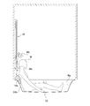
図1は、第3使用態様にあるときの使用例を示す図でもある。第3使用態様にあるとき、座部材16は、槽部24の上部開口部に脚入れ口24dが残るように槽部24の一方側部分を上側から部分的に覆う。座部材16は、浴槽12の槽部24を上側から覆うとき、このような脚入れ口24dが槽部242の上部開口部に形成されるように、その寸法や形状が設定されているといえる。これにより、入浴者Hは、自らの両脚の一部を脚入れ口24dから浴槽12内に入れた状態で座部材16に座る座位姿勢をとれる。
浴槽12の載せ面部28上の座部材16は、位置決め構造18により長手方向Xや短手方向Yに位置決めされる。詳しくは、座部材16は、背もたれ部材14の第1位置決め部18aとの当接により、座部材16の背側(吐水具20、22に近づく側)に向かう変位が規制されるように長手方向Xに位置決めされる。また、座部材16は、浴槽12の第2位置決め部18bとの当接により、短手方向Yでの変位が規制されるように短手方向Yに位置決めされる。
第1吐水具20は、位置決め構造18により位置決めされた座部材16上に入浴者Hが座る座位姿勢にあるとき、入浴者Hの腰部に当たるように水を吐き出し可能である。この条件を満たすうえで、第1吐水具20の吐出角度を調整してもよい。第2吐水具22は、前述の座位姿勢に入浴者Hがあるとき、入浴者Hの肩部に当たるように水を吐き出し可能である。この条件を満たすうえで、第2吐水具22の浴槽12に対する相対位置、吐出方向や吐出角度を調整してもよい。このように、第2吐水具22は、第1吐水具20による水当て位置より高位置で入浴者Hに当たるように水を吐き出し可能である。言い換えると、第2吐水具22は、第1吐水具20による水当て位置とは上下方向の異なる位置で入浴者Hに当たるように水を吐き出し可能である。
第1吐水具20は、座部材16上に座位姿勢にある入浴者Hの腰部より腰幅方向(短手方向Y)に広い範囲を通るように、座部材16の背側の第1浴槽側浴室壁部34-Aの正面側に向けて水を吐き出す。第2吐水具22は、第1浴槽側浴室壁部34-Aの法線方向に第2吐水具22の吐出方向を合わせたとき、第1吐水具20から吐き出される水の通過範囲より短手方向Yに狭い範囲を通るように水を吐き出す。このように、第1吐水具20と第2吐水具22とは、吐き出された水が異なる範囲を通るように、異なる水の吐出態様をもっている。このような条件を満たすように、第1吐水具20及び第2吐水具22それぞれの吐出口の数、位置等が設定されている。
以上のように、第1吐水具20や第2吐水具22は、位置決め構造18により位置決めされた座部材16上に座る入浴者Hに当たるように水を吐き出し可能である。これにより、前述の座位姿勢にあるとき、浴槽12内に溜めた水に両脚の一部を入れしつつ、吐水具20、22から吐き出された水を入浴者Hが浴びられる。このため、入浴者Hの上半身を浴槽12内の水に漬けないことで心肺への負担を抑えつつ、入浴者Hが座位姿勢のまま足元や上半身を暖められ、高いリラックス効果を得られる。
図10は、第3使用態様にあるときの他の使用態様を示す図である。第2吐水具22は、浴槽12に対する相対位置を保持する他部材としてのシャワーフック40に対して着脱可能である。よって、入浴者Hが座部材16上に座位姿勢にあるとき、シャワーフック40から第2吐水具22を取り外したうえで入浴者Hが手に持ち、入浴者Hの好みの箇所に第2吐水具22から吐き出される水Wbを浴びせられる。これにより、入浴者Hが座位姿勢のまま足浴しつつ、入浴者Hの好みの箇所に水浴びでき、より高いリラックス効果を得られる。
本実施形態の浴槽装置10の作用効果を説明する。
浴槽装置10によれば、入浴者Hが座部材16上に座る座位姿勢にあるとき、浴槽12内の水に脚を入れつつ、吐水具20、22から吐き出された水を浴びられる。よって、入浴者Hが座部材16上に座位姿勢のまま足浴しつつ水浴びでき、新しい態様の水浴びを実現するのに適した浴槽装置10を得られる。
浴槽装置10によれば、入浴者Hが座部材16上に座る座位姿勢にあるとき、浴槽12内の水に脚を入れつつ、吐水具20、22から吐き出された水を浴びられる。よって、入浴者Hが座部材16上に座位姿勢のまま足浴しつつ水浴びでき、新しい態様の水浴びを実現するのに適した浴槽装置10を得られる。
浴槽装置10は、座部材16との当接により座部材16を位置決めするための位置決め構造18を備える。よって、入浴者Hが座部材16上に座位姿勢にあるとき、浴槽12に対する座部材16の位置ずれを位置決め構造18との当接により規制でき、安定して座位姿勢をとり続け易くなる。
第1吐水具20や第2吐水具22は、浴槽12に対する相対位置が他部材(ブラケット36、シャワーフック40)により保持される。よって、入浴者Hが座部材16上に座位姿勢にあるとき、両手を自由にしたままで吐水具20、22から吐き出される水を浴びられ、より高いリラックス効果を得やすくなる。
第1吐水具20や第2吐水具22は、位置決め構造18の第1位置決め部18aと座部材16との当接位置より座部材16の背側にオフセットした位置に配置される。よって、入浴者Hが長手方向Xの背側とは反対側を向いた状態で座部材16上に座ったとき、入浴者Hから長手方向Xの背側に離れた位置に各吐水具20、22が配置され、入浴者Hと各吐水具20、22との干渉を抑え易くなる。このため、各吐水具20、22との干渉を気にせず、入浴者Hが座部材16上に深く腰かけた状態で足浴しつつ水浴びでき、より高いリラックス効果を得やすくなる。
なお、このような作用効果を得るうえで、浴槽12に対する相対位置や吐出角度を調整できる第2吐水具22に関しては、その調整可能な範囲の少なくとも一部において、前述の当接位置Paより座部材16の背側にオフセットした位置に配置されていればよい。
吐水具20、22には同時に水を吐き出し可能な複数の吐水具20、22が含まれる。よって、入浴者Hが座部材16上に座位姿勢にあるとき、複数の吐水具20、22から同時に水を吐き出すことで、入浴者Hの身体の広い範囲で多くの水を浴び易くなり、高いリラックス効果をより得やすくなる。
吐水具20、22には、上下方向の異なる位置で入浴者Hに当たるように水を吐き出し可能な複数の吐水具20、22が含まれる。よって、入浴者Hが座部材16上に座位姿勢にあるとき、複数の箇所から好みの箇所に水浴び位置を選択でき、入浴者Hが座位姿勢で水浴びするうえでの使い勝手が良好になる。
また、第2吐水具22は、浴槽12に対する相対位置を調整して保持可能である。よって、第2吐水具22の吐出位置を入浴者Hの好みに応じて調整でき、入浴者Hが座部材16上に座位姿勢で水浴びするうえでの使い勝手が良好になる。
また、第2吐水具22は、浴槽12に対する相対位置を上下方向に調整して保持可能である。よって、入浴者Hの身長に応じて、入浴者Hの肩部や頭部等に水を当てるのに適した位置に配置されるように、第2吐水具22の吐出位置を上下方向に調整でき、入浴者Hが座部材16上に座位姿勢で水浴びするうえでの使い勝手が良好になる。
本実施形態の浴槽装置10の他の特徴を説明する。
図7に示すように、第2吐水具22は、平面視において、槽部24の短手方向Yの中心線Lcに対して重なる位置に配置されるように、浴槽12に対する相対位置を調整可能である。ここでの槽部24の短手方向Yの中心線Lcとは、平面視において、槽部24の短手方向Yでの最大内幅寸法Saを二等分する位置Pb(短手方向Yの中心位置)を通るとともに長手方向Xに沿って延びる線をいう。このような位置に第2吐水具22が配置されている場合、入浴者Hの座部材16に対する座位置を短手方向Yに微調整するだけで、入浴者Hの左右中央部に対して座部材16の背側に第2吐水具22を配置できる。この位置関係のもと、第2吐水具22から水が吐き出されると、入浴者Hの左右方向の広い範囲で水浴びし易くなる。よって、第2吐水具22の吐出位置の調整により使い勝手を良好にしつつ、入浴者Hの身体の広い範囲での水浴びにより高いリラックス効果を得やすくなる。
図7に示すように、第2吐水具22は、平面視において、槽部24の短手方向Yの中心線Lcに対して重なる位置に配置されるように、浴槽12に対する相対位置を調整可能である。ここでの槽部24の短手方向Yの中心線Lcとは、平面視において、槽部24の短手方向Yでの最大内幅寸法Saを二等分する位置Pb(短手方向Yの中心位置)を通るとともに長手方向Xに沿って延びる線をいう。このような位置に第2吐水具22が配置されている場合、入浴者Hの座部材16に対する座位置を短手方向Yに微調整するだけで、入浴者Hの左右中央部に対して座部材16の背側に第2吐水具22を配置できる。この位置関係のもと、第2吐水具22から水が吐き出されると、入浴者Hの左右方向の広い範囲で水浴びし易くなる。よって、第2吐水具22の吐出位置の調整により使い勝手を良好にしつつ、入浴者Hの身体の広い範囲での水浴びにより高いリラックス効果を得やすくなる。
スライドバー42は、槽部24の長手方向Xの一方側にある第1浴槽側浴室壁部34-Aに取り付けられる。スライドバー42は、槽部24の短手方向Yの中心線Lcに対して短手方向Yにオフセットした位置に配置される。スライドバー42は、平面視において、この槽部24の中心線Lcと重ならない位置に配置されることになる。本実施形態では、槽部24の中心線Lcからスライドバー42が短手方向Yにオフセットした量であるオフセット量は、槽部24の最大内幅寸法Saを四等分した大きさを基準寸法Sbとしたとき、基準寸法Sbより大きくなるように設定されている。第1浴槽側浴室壁部34-Aは、鋼板等の内装材と、内装材の裏面に裏打ちされた石膏ボード等の構造用面材とを備える。スライドバー42は、締結具を用いて第1浴槽側浴室壁部34-Aに締結するうえで、第1浴槽側浴室壁部34-Aの構造用面材に締結具を締結可能な位置に配置される。
以上の浴槽装置10によれば、スライドバー42が槽部24の短手方向Yの中心線Lcに対して短手方向Yにオフセットした位置に配置される。よって、図8を用いて説明したように、浴槽12に腰をおろして両脚を突き出した座位姿勢になったとき、入浴者Hの頭部がスライドバー42に当たり難くなる利点がある。また、平面視において、槽部24の中心線Lcの近傍で第1浴槽側浴室壁部34-Aの内側面に他部品を設置するスペースSc(図5参照)を確保できる。このスペースScに鏡や棚を設置することで、浴槽12内で洗体行為をし易くなる利点がある。
本実施形態の浴槽装置10はシャワー装置38にも特徴がある。
図3、図5に示すように、シャワー装置38は、第2吐水具22(シャワーヘッド)と、シャワーフック40と、スライドバー42と、シャワーホース44とを備える。第2吐水具22やシャワーフック40の詳細は前述の通りである。
図3、図5に示すように、シャワー装置38は、第2吐水具22(シャワーヘッド)と、シャワーフック40と、スライドバー42と、シャワーホース44とを備える。第2吐水具22やシャワーフック40の詳細は前述の通りである。
スライドバー42は、シャワーフック40を上下方向にスライド可能に支持するバー状をなし、その上側部分と下側部分とがブラケット36B、36Cにより支持される。ブラケット36B、36Cは、スライドバー42の下側部分を支持する下側ブラケット36Bと、スライドバー42の上側部分を支持する上側ブラケット36Cとを含む。下側ブラケット36Bは、第1吐水具20を支持するブラケットでもある。
下側ブラケット36Bや上側ブラケット36Cは、シャワーフック40と当接することにより、スライドバー42に対するシャワーフック40のスライド可能範囲Sdを定める。下側ブラケット36Bは、シャワーフック40と当接することにより、シャワーフック40のスライド可能範囲Sdの下限位置を定める。上側ブラケット36Cは、シャワーフック40と当接することにより、シャワーフック40のスライド可能範囲Sdの上限位置を定める。
シャワーホース44は、第2吐水具22に給水するためのものであり、可とう性をもつ。シャワーホース44は、本実施形態において、上側ブラケット36Cから引き出されており、上側ブラケット36やスライドバー42の内部に形成される前述の給水路を通して給水される。シャワーホース44は、シャワーフック40のスライド可能範囲Sdの上下方向での中心位置Pcより高位置に基端部44aが配置される。本実施形態のシャワーホース44は、シャワーフック40のスライド可能範囲Sdの上限位置と同等の高さ位置に基端部44aが配置される。
以上のシャワー装置38によれば、シャワーフック40のスライド可能範囲Sdの中心位置Pcより高位置にシャワーホース44の基端部44aが配置される。よって、シャワーフック40をスライド可能範囲Sdの下限位置に近づけたとき、シャワーホース44の中間部が浴槽12内の浴槽水に漬かり難くなる。入浴者Hの心理面や衛生面からは浴槽水に物品が漬かるのを避ける方が好ましい。このため、本実施形態によれば、シャワーホース44が浴槽水に漬かることによる悪影響の発生を防止できる。
なお、このような作用効果を得る観点からは、シャワーホース44の基端部44aは、シャワーフック40のスライド可能範囲Sdの上限位置と同等又はそれ以上の高さ位置に配置されてもよい。本明細書での「同等」には比較対象となる両者が同一の場合とほぼ同一の場合との両方が含まれる。
[第2実施形態]
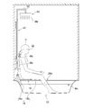
図11は、第2実施形態の浴槽装置10の使用例を示す図である。第2実施形態の浴槽装置10は、第1実施形態と比べて、吐水具20、22、50に第3吐水具50が含まれる点が相違する。第3吐水具50は、第2吐水具22より高位置に配置されるシャワーヘッドである。第3吐水具50には、スライドバー42の上端部から延び出る中継管52が接続される。中継管52の内部には第1吐水具20や第2吐水具22に給水するための給水路の一部が分岐して形成され、第3吐水具50には給水路を通して給水される。第3吐水具50は、不図示のハンドルに対する操作を受けて、吐出動作の有無が切り替えられる。
図11は、第2実施形態の浴槽装置10の使用例を示す図である。第2実施形態の浴槽装置10は、第1実施形態と比べて、吐水具20、22、50に第3吐水具50が含まれる点が相違する。第3吐水具50は、第2吐水具22より高位置に配置されるシャワーヘッドである。第3吐水具50には、スライドバー42の上端部から延び出る中継管52が接続される。中継管52の内部には第1吐水具20や第2吐水具22に給水するための給水路の一部が分岐して形成され、第3吐水具50には給水路を通して給水される。第3吐水具50は、不図示のハンドルに対する操作を受けて、吐出動作の有無が切り替えられる。
第3吐水具50は、前述のような、浴槽12上に入浴者Hが立った立位姿勢にあるとき、シャワー状の水Wbを吐き出すオーバーヘッドシャワーとして用いられる。また、入浴者Hが座部材16上に座位姿勢にあるとき、図11に示すように、第1吐水具20や第2吐水具22と組み合わせて用いてもよい。この場合に、第3吐水具50も第1吐水具20や第2吐水具22と同時に水を吐き出し可能に構成してもよい。
[第3実施形態]
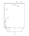
図12は、第3実施形態の浴槽装置10を示す図である。第3実施形態の浴槽装置10は、第1実施形態と比べて、浴室の天井54にシャワーヘッド56が埋め込まれている点が相違する。シャワーヘッド56には、不図示の給水路を通して給水される。シャワーヘッド56は、図示しないが、浴槽12上に入浴者Hが立った立位姿勢にあるとき、入浴者Hの頭部に向けてシャワー状の水Wbを吐き出すオーバーヘッドシャワーとして用いられる。シャワーヘッド56は、不図示のハンドルに対する操作を受けて、吐出動作の有無が切り替えられる。
図12は、第3実施形態の浴槽装置10を示す図である。第3実施形態の浴槽装置10は、第1実施形態と比べて、浴室の天井54にシャワーヘッド56が埋め込まれている点が相違する。シャワーヘッド56には、不図示の給水路を通して給水される。シャワーヘッド56は、図示しないが、浴槽12上に入浴者Hが立った立位姿勢にあるとき、入浴者Hの頭部に向けてシャワー状の水Wbを吐き出すオーバーヘッドシャワーとして用いられる。シャワーヘッド56は、不図示のハンドルに対する操作を受けて、吐出動作の有無が切り替えられる。
以上、本発明の実施形態の例について詳細に説明した。前述した実施形態は、いずれも本発明を実施するにあたっての具体例を示したものにすぎない。実施形態の内容は、本発明の技術的範囲を限定するものではなく、請求の範囲に規定された発明の思想を逸脱しない範囲において、構成要素の変更、追加、削除等の多くの設計変更が可能である。前述の実施形態では、このような設計変更が可能な内容に関して、「実施形態の」「実施形態では」等との表記を付して説明しているが、そのような表記のない内容に設計変更が許容されないわけではない。また、図面の断面に付したハッチングは、ハッチングを付した対象の材質を限定するものではない。
浴槽12の載せ面部28は浴槽12の短手方向Yに対向する位置に設けられる例を説明したが、その位置は特に限られない。たとえば、浴槽12の長手方向Xに対向する位置に設けられてもよい。浴槽12の載せ面部28はフランジ部26の内周縁部に設けられる例を説明したが、フランジ部26の内周縁部より外周側部分に設けられてもよいし、槽部24の上下方向の途中位置に設けられてもよい。
位置決め構造18は、槽部24の長手方向X及び短手方向Yのうち、少なくとも一方の方向に座部材16を位置決めできればよい。実施形態の位置決め構造18は、座部材16の長手方向Xの一方側の端辺部に当接することにより、座部材16を長手方向Xに位置決めする例を説明した。この他にも、位置決め構造18は、座部材16の短手方向Yの一方側の端辺部に当接することにより、座部材16を短手方向Yに位置決めしてもよい。この場合、吐水具20、22は、位置決め構造18と座部材16との当接位置より短手方向Yの一方側にオフセットした位置に配置されてもよい。つまり、槽部24の長手方向X及び短手方向Yのうちの一方を第1方向としたとき、位置決め構造18は、座部材16の第1方向の一方側の端辺部に当接することにより、座部材16を位置決め可能としてよく、吐水具20、22は、位置決め構造18と座部材16との当接位置より第1方向の一方側にオフセットした位置に配置されてもよい。このとき、座部材16は、槽部24の上部開口部に脚入れ口24dが残るように槽部24の第1方向の一方側部分を覆うことになる。また、吐水具20、22は、位置決め構造18により位置決めされた座部材16を挟んで脚入れ口24dとは第1方向の反対側に配置されることにもなる。
実施形態の位置決め構造18は、背もたれ部材14の背もたれ面14aが第1位置決め部18aである例を説明したが、これに限られない。たとえば、浴槽12のフランジ部26に上向きに突き出る凸部を設け、その凸部を第1位置決め部としても用いてもよい。この場合、座部材16の端辺部と凸部との当接により座部材16が位置決めされる。また、この他にも、位置決め構造18は、浴槽側浴室壁部34-Aa~34-Acのいずれかが構成してもよい。この場合、たとえば、第1浴槽側浴室壁部34-Aaを第1位置決め部18aとし、第3浴槽側浴室壁部34-Abを第2位置決め部18bとしてもよい。また、この他にも、位置決め構造18は、たとえば、浴槽12のフランジ部26等に設けられた第1嵌合部と、座部材16の下面に設けられ、第1嵌合部と嵌め合う第2嵌合部とを備えていてもよい。この場合、第1嵌合部は凸部又は凹部であり、第2嵌合部は第1嵌合部と嵌め合う凹部又は凸部となる。この場合、浴槽12の第1嵌合部と座部材16の第2嵌合部との嵌め合いにより座部材16が長手方向X及び短手方向Yの両方に位置決めされる。
浴槽装置10は複数の吐水具20、22を備える例を説明したが、少なくとも一つの吐水具20、22があればよい。たとえば、第1実施形態の第1吐水具20及び第2吐水具22の何れかのみを備えていてもよいし、第2実施形態の第3吐水具50のみを備えていてもよい。
吐水具20、22は、複数の吐出口からシャワー状の水を吐き出すものを例に説明したが、これに限られない。たとえば、吐水具20、22は、吐出口から膜状又は柱状の整流水を吐き出すものでもよい。
第1吐水具20はブラケット36により保持され、第2吐水具22はシャワーフック40により保持される例を説明した。このように、吐水具20、22は他部材(ブラケット36、シャワーフック40)により保持されていてもよい。ここでの他部材は、特に限られず、浴室壁部34や浴槽12等も含まれる。
吐水具20、22は、座部材16の背側にある第1浴槽側浴室壁部34-Aaに取り付けられる例を説明したが、これに限られず、座部材16の背側にある浴槽12の後フランジ部26Aに取り付けられてもよい。また、吐水具20、22は、座部材16の背側ではなく、座部材16の横側にある第3浴槽側浴室壁部34-Acや、浴槽12の右フランジ部26Cに取り付けられてもよい。つまり、吐水具20、22は、浴槽側浴室壁部34-Aa~Acや浴槽12に直接又は他部材を介して取り付けられていてもよい。言い換えると、吐水具20、22は、床側浴室壁部34-Bには直接又は他部材を介して取り付けられていないともいえる。これら何れの場合でも、吐水具20、22は、浴槽12に隣り合う位置にある床102の上方ではなく、浴槽12の上方に全体が配置されることになる。別の観点から見ると、吐水具20、22の吐出口の全てが浴槽12の上方に配置されることになる。
本実施形態の浴槽装置10は背もたれ部材14を備える例を説明したが、背もたれ部材14はなくともよい。また、背もたれ部材14は、クッション性のある軟質素材を用いて構成される例を説明したが、その一部にクッション性のない硬質素材を設けてもよい。また、背もたれ部材14は、クッション性のない硬質素材を用いて構成してもよいし、その一部にクッション性のある軟質素材を設けてもよい。
シャワー装置38は、シャワーフック40のスライド可能範囲Sdの中心位置Pcより高位置にシャワーホース44の基端部44aが配置されていればよく、シャワーホース44の引き出し位置は上側ブラケット36に限られない。たとえば、シャワーホース44の引き出し位置は、上側ブラケット36の他にも、スライドバー42又は浴室壁部34でもよい。
本実施形態の間仕切り106は、引き戸として機能する可動壁106aと、固定壁106bとを有する例を説明したが、その壁の種類や数はこれに限られない。たとえば、固定壁106bの代替として他の可動壁を用いてもよい。また、可動壁は開き戸等として機能してもよい。
以上の実施形態、変形例により具体化される発明を一般化すると、以下の技術的思想が導かれる。以下、発明が解決しようとする課題に記載の態様を用いて説明する。
第2態様の浴槽装置は、第1態様において、前記吐水具は、前記浴槽の端辺部から立ち上がる浴槽側浴室壁部又は前記浴槽に取り付けられてもよい。
第3態様の浴槽装置は、第1態様又は第2態様において、前記槽部の長手方向及び短手方向のうちの一方を第1方向としたとき、前記位置決め構造は、前記座部材の前記第1方向の端辺部に当接することにより、前記座部材を位置決め可能な位置決め部を有し、前記吐水具は、前記位置決め部と前記座部材との当接位置より前記第1方向の一方側にオフセットした位置に配置されてもよい。
この態様によれば、入浴者が第1方向の一方側とは反対側を向いた状態で座部材上に座ったとき、入浴者から第1方向の一方側に離れた位置に吐水具が配置され、入浴者と吐水具との干渉を抑え易くなる。このため、吐水具との干渉を気にせず、入浴者が座部材上に深く腰かけた状態で足浴しつつ水浴びでき、高いリラックス効果を得やすくなる。
この態様によれば、入浴者が第1方向の一方側とは反対側を向いた状態で座部材上に座ったとき、入浴者から第1方向の一方側に離れた位置に吐水具が配置され、入浴者と吐水具との干渉を抑え易くなる。このため、吐水具との干渉を気にせず、入浴者が座部材上に深く腰かけた状態で足浴しつつ水浴びでき、高いリラックス効果を得やすくなる。
第4態様の浴槽装置は、第1態様から第3態様のいずれかにおいて、前記吐水具には同時に水を吐き出し可能な複数の吐水具が含まれてもよい。
この態様によれば、入浴者が座部材上に座位姿勢にあるとき、入浴者の身体の広い範囲で多くの水を浴び易くなり、高いリラックス効果をより得やすくなる。
この態様によれば、入浴者が座部材上に座位姿勢にあるとき、入浴者の身体の広い範囲で多くの水を浴び易くなり、高いリラックス効果をより得やすくなる。
第5態様の浴槽装置は、第1態様から第4態様のいずれかにおいて、前記吐水具には、上下方向の異なる位置で入浴者に当たるように水を吐き出し可能な複数の吐水具が含まれてもよい。
この態様によれば、入浴者が座部材上に座位姿勢にあるとき、複数の箇所から好みの箇所に水浴び位置を選択でき、入浴者が座位姿勢で水浴びするうえでの使い勝手が良好になる。
この態様によれば、入浴者が座部材上に座位姿勢にあるとき、複数の箇所から好みの箇所に水浴び位置を選択でき、入浴者が座位姿勢で水浴びするうえでの使い勝手が良好になる。
第6態様の浴槽装置は、第1態様から第5態様のいずれかにおいて、前記吐水具は、前記浴槽に対する相対位置を調整して保持可能であってもよい。
この態様によれば、吐水具の吐出位置を入浴者の好みに応じて調整でき、入浴者が座部材上に座位姿勢で水浴びするうえでの使い勝手が良好になる。
この態様によれば、吐水具の吐出位置を入浴者の好みに応じて調整でき、入浴者が座部材上に座位姿勢で水浴びするうえでの使い勝手が良好になる。
第7態様の浴槽装置は、第6態様において、前記吐水具は、前記浴槽に対する相対位置を上下方向に調整可能であってもよい。
この態様によれば、入浴者の身長に応じて、入浴者の肩部や頭部等に水を当てるのに適した位置に配置されるように、吐水具の吐出位置を上下方向に調整でき、入浴者が座部材上に座位姿勢で水浴びするうえでの使い勝手が良好になる。
この態様によれば、入浴者の身長に応じて、入浴者の肩部や頭部等に水を当てるのに適した位置に配置されるように、吐水具の吐出位置を上下方向に調整でき、入浴者が座部材上に座位姿勢で水浴びするうえでの使い勝手が良好になる。
第8態様の浴槽装置は、第6態様又は第7態様において、前記座部材は、前記槽部の長手方向の一方側部分を部分的に覆うように前記位置決め構造により位置決めされ、前記吐水具は、前記位置決め構造により位置決めされた前記座部材に対して前記長手方向の一方側に配置され、かつ、前記槽部の短手方向の中心線に対して重なる位置に配置されるように、前記浴槽に対する相対位置を調整可能であってもよい。
この態様によれば、浴槽に対する吐水具の相対位置を調整しつつ、入浴者の座部材に対する座位置を微調整するだけで、入浴者の左右方向の広い範囲で水浴びし易くなる。よって、吐水具の吐出位置の調整により使い勝手を良好にしつつ、入浴者の身体の広い範囲での水浴びにより高いリラックス効果を得やすくなる。
この態様によれば、浴槽に対する吐水具の相対位置を調整しつつ、入浴者の座部材に対する座位置を微調整するだけで、入浴者の左右方向の広い範囲で水浴びし易くなる。よって、吐水具の吐出位置の調整により使い勝手を良好にしつつ、入浴者の身体の広い範囲での水浴びにより高いリラックス効果を得やすくなる。
また、以上の実施形態、変形例により具体化される発明を一般化すると、以下の項目に記載の発明が含まれているともいえる。
(項目)
シャワーヘッドと、
前記シャワーヘッドを保持するシャワーフックと、
前記シャワーフックを上下方向にスライド可能に支持するスライドバーと、
前記シャワーヘッドに水を供給するためのシャワーホースと、を備え、
前記シャワーホースの基端部は、前記シャワーフックのスライド可能範囲の上下方向での中心位置より高位置に配置されていることを特徴とするシャワー装置。
(項目)
シャワーヘッドと、
前記シャワーヘッドを保持するシャワーフックと、
前記シャワーフックを上下方向にスライド可能に支持するスライドバーと、
前記シャワーヘッドに水を供給するためのシャワーホースと、を備え、
前記シャワーホースの基端部は、前記シャワーフックのスライド可能範囲の上下方向での中心位置より高位置に配置されていることを特徴とするシャワー装置。
10…浴槽装置、12…浴槽、16…座部材、18…位置決め構造、18a,18b…位置決め部、20…第1吐水具、22…第2吐水具、24…槽部、24d…脚入れ口、28…載せ面部。
本発明は、浴室に用いられる浴槽装置に関する。
Claims (8)
- 槽部を上側から部分的に覆う座部材を載せるための載せ面部を有する浴槽と、
前記載せ面部上の前記座部材を位置決めするための位置決め構造と、
前記位置決め構造により位置決めされた前記座部材上に座る入浴者に当たるように水を吐き出し可能な吐水具と、を備えることを特徴とする浴槽装置。 - 前記吐水具は、前記浴槽の端辺部から立ち上がるように設けられる浴槽側浴室壁部又は前記浴槽に取り付けられる請求項1に記載の浴槽装置。
- 前記槽部の長手方向及び短手方向のうちの一方を第1方向としたとき、
前記位置決め構造は、前記座部材の前記第1方向の一方側の端辺部に当接することにより、前記座部材を前記第1方向に位置決め可能であり、
前記吐水具は、前記位置決め構造と前記座部材との当接位置より前記第1方向の一方側にオフセットした位置に配置される請求項1又は2に記載の浴槽装置。 - 前記吐水具には、同時に水を吐き出し可能な複数の吐水具が含まれる請求項1から3のいずれかに記載の浴槽装置。
- 前記吐水具には、上下方向の異なる位置で入浴者に当たるように水を吐き出し可能な複数の吐水具が含まれる請求項1から4のいずれかに記載の浴槽装置。
- 前記吐水具は、前記浴槽に対する相対位置を調整して保持可能である請求項1から5のいずれかに記載の浴槽装置。
- 前記吐水具は、前記浴槽に対する相対位置を上下方向に調整可能である請求項6に記載の浴槽装置。
- 前記座部材は、前記槽部の長手方向の一方側部分を部分的に覆うように前記位置決め構造により位置決めされ、
前記吐水具は、前記位置決め構造により位置決めされた前記座部材に対して前記長手方向の一方側に配置され、かつ、
前記槽部の短手方向の中心線に対して重なる位置に配置されるように、前記浴槽に対する相対位置を調整可能である請求項6又は7に記載の浴槽装置。
Applications Claiming Priority (2)
| Application Number | Priority Date | Filing Date | Title |
|---|---|---|---|
| JP2016116713A JP7171159B2 (ja) | 2016-06-10 | 2016-06-10 | 浴槽装置 |
| JP2016-116713 | 2016-06-10 |
Publications (1)
| Publication Number | Publication Date |
|---|---|
| WO2017212834A1 true WO2017212834A1 (ja) | 2017-12-14 |
Family
ID=60578604
Family Applications (1)
| Application Number | Title | Priority Date | Filing Date |
|---|---|---|---|
| PCT/JP2017/017165 Ceased WO2017212834A1 (ja) | 2016-06-10 | 2017-05-01 | 浴槽装置 |
Country Status (2)
| Country | Link |
|---|---|
| JP (1) | JP7171159B2 (ja) |
| WO (1) | WO2017212834A1 (ja) |
Families Citing this family (1)
| Publication number | Priority date | Publication date | Assignee | Title |
|---|---|---|---|---|
| JP7507644B2 (ja) * | 2020-09-16 | 2024-06-28 | 株式会社Lixil | 吐水装置および吐水方法 |
Citations (4)
| Publication number | Priority date | Publication date | Assignee | Title |
|---|---|---|---|---|
| JPH0274980U (ja) * | 1988-11-28 | 1990-06-07 | ||
| JPH0427884U (ja) * | 1990-06-28 | 1992-03-05 | ||
| JP2003278197A (ja) * | 2002-03-25 | 2003-10-02 | Toto Ltd | 水栓兼用手すりの構造 |
| JP2006263231A (ja) * | 2005-03-24 | 2006-10-05 | Sekisui Home Techno Kk | 浴槽 |
Family Cites Families (6)
| Publication number | Priority date | Publication date | Assignee | Title |
|---|---|---|---|---|
| JPH0646971B2 (ja) * | 1986-05-28 | 1994-06-22 | 大阪瓦斯株式会社 | シヤワ−装置付き浴槽装置 |
| JPH06125854A (ja) * | 1992-10-20 | 1994-05-10 | Sekisui Chem Co Ltd | 浴槽シャワー装置 |
| JP3446927B2 (ja) * | 1996-07-26 | 2003-09-16 | サンウエーブ工業株式会社 | 浴槽装置 |
| JPH10117959A (ja) * | 1996-10-21 | 1998-05-12 | Sekisui Chem Co Ltd | 入浴用椅子 |
| JP2000166788A (ja) * | 1998-12-04 | 2000-06-20 | Sekisui Chem Co Ltd | 浴 槽 |
| JP2001292923A (ja) | 2000-04-11 | 2001-10-23 | Sekisui Chem Co Ltd | 移乗台付浴槽および浴室 |
-
2016
- 2016-06-10 JP JP2016116713A patent/JP7171159B2/ja active Active
-
2017
- 2017-05-01 WO PCT/JP2017/017165 patent/WO2017212834A1/ja not_active Ceased
Patent Citations (4)
| Publication number | Priority date | Publication date | Assignee | Title |
|---|---|---|---|---|
| JPH0274980U (ja) * | 1988-11-28 | 1990-06-07 | ||
| JPH0427884U (ja) * | 1990-06-28 | 1992-03-05 | ||
| JP2003278197A (ja) * | 2002-03-25 | 2003-10-02 | Toto Ltd | 水栓兼用手すりの構造 |
| JP2006263231A (ja) * | 2005-03-24 | 2006-10-05 | Sekisui Home Techno Kk | 浴槽 |
Also Published As
| Publication number | Publication date |
|---|---|
| JP7171159B2 (ja) | 2022-11-15 |
| JP2017217421A (ja) | 2017-12-14 |
Similar Documents
| Publication | Publication Date | Title |
|---|---|---|
| US8826472B2 (en) | Bath system | |
| US9462885B2 (en) | Bathing area accessories | |
| WO2017212834A1 (ja) | 浴槽装置 | |
| JP2003278197A (ja) | 水栓兼用手すりの構造 | |
| JP2004049677A (ja) | 浴室装置 | |
| JP3612509B2 (ja) | シャワー器具 | |
| EP2153765A2 (en) | Bath system | |
| JP5732610B2 (ja) | シャワー浴装置 | |
| JP4473761B2 (ja) | シャワー装置 | |
| JPH0444158Y2 (ja) | ||
| EP2153762A2 (en) | Bath system | |
| JP4725299B2 (ja) | 浴室ユニット | |
| JP2018186965A (ja) | 浴室ユニット | |
| JP4473758B2 (ja) | シャワー装置 | |
| JP2007135638A (ja) | 浴槽及び浴室ユニット | |
| JP2007138391A (ja) | 浴室ユニット | |
| EP2153764A2 (en) | Bath system | |
| JP2004313724A (ja) | 足湯装置付浴槽 | |
| JP2019044373A (ja) | 浴室ユニット | |
| EP2153761A2 (en) | Bath system | |
| JPH09289955A (ja) | 洗面器置き台 | |
| JP2006230450A (ja) | 浴室のスクリーン構造 | |
| ITMN930017A1 (it) | Cabina igienico sanitaria polifunzionale |
Legal Events
| Date | Code | Title | Description |
|---|---|---|---|
| 121 | Ep: the epo has been informed by wipo that ep was designated in this application |
Ref document number: 17810016 Country of ref document: EP Kind code of ref document: A1 |
|
| NENP | Non-entry into the national phase |
Ref country code: DE |
|
| 122 | Ep: pct application non-entry in european phase |
Ref document number: 17810016 Country of ref document: EP Kind code of ref document: A1 |