WO2017209141A1 - 組電池および電池セル - Google Patents
組電池および電池セル Download PDFInfo
- Publication number
- WO2017209141A1 WO2017209141A1 PCT/JP2017/020140 JP2017020140W WO2017209141A1 WO 2017209141 A1 WO2017209141 A1 WO 2017209141A1 JP 2017020140 W JP2017020140 W JP 2017020140W WO 2017209141 A1 WO2017209141 A1 WO 2017209141A1
- Authority
- WO
- WIPO (PCT)
- Prior art keywords
- battery cells
- battery
- electrode terminal
- assembled battery
- electrically connected
- Prior art date
Links
Images


Classifications
-
- H—ELECTRICITY
- H01—ELECTRIC ELEMENTS
- H01M—PROCESSES OR MEANS, e.g. BATTERIES, FOR THE DIRECT CONVERSION OF CHEMICAL ENERGY INTO ELECTRICAL ENERGY
- H01M50/00—Constructional details or processes of manufacture of the non-active parts of electrochemical cells other than fuel cells, e.g. hybrid cells
- H01M50/20—Mountings; Secondary casings or frames; Racks, modules or packs; Suspension devices; Shock absorbers; Transport or carrying devices; Holders
- H01M50/267—Mountings; Secondary casings or frames; Racks, modules or packs; Suspension devices; Shock absorbers; Transport or carrying devices; Holders having means for adapting to batteries or cells of different types or different sizes
-
- H—ELECTRICITY
- H01—ELECTRIC ELEMENTS
- H01M—PROCESSES OR MEANS, e.g. BATTERIES, FOR THE DIRECT CONVERSION OF CHEMICAL ENERGY INTO ELECTRICAL ENERGY
- H01M50/00—Constructional details or processes of manufacture of the non-active parts of electrochemical cells other than fuel cells, e.g. hybrid cells
- H01M50/20—Mountings; Secondary casings or frames; Racks, modules or packs; Suspension devices; Shock absorbers; Transport or carrying devices; Holders
- H01M50/204—Racks, modules or packs for multiple batteries or multiple cells
- H01M50/207—Racks, modules or packs for multiple batteries or multiple cells characterised by their shape
- H01M50/211—Racks, modules or packs for multiple batteries or multiple cells characterised by their shape adapted for pouch cells
-
- H—ELECTRICITY
- H01—ELECTRIC ELEMENTS
- H01M—PROCESSES OR MEANS, e.g. BATTERIES, FOR THE DIRECT CONVERSION OF CHEMICAL ENERGY INTO ELECTRICAL ENERGY
- H01M50/00—Constructional details or processes of manufacture of the non-active parts of electrochemical cells other than fuel cells, e.g. hybrid cells
- H01M50/50—Current conducting connections for cells or batteries
- H01M50/502—Interconnectors for connecting terminals of adjacent batteries; Interconnectors for connecting cells outside a battery casing
- H01M50/503—Interconnectors for connecting terminals of adjacent batteries; Interconnectors for connecting cells outside a battery casing characterised by the shape of the interconnectors
-
- H—ELECTRICITY
- H01—ELECTRIC ELEMENTS
- H01M—PROCESSES OR MEANS, e.g. BATTERIES, FOR THE DIRECT CONVERSION OF CHEMICAL ENERGY INTO ELECTRICAL ENERGY
- H01M50/00—Constructional details or processes of manufacture of the non-active parts of electrochemical cells other than fuel cells, e.g. hybrid cells
- H01M50/50—Current conducting connections for cells or batteries
- H01M50/502—Interconnectors for connecting terminals of adjacent batteries; Interconnectors for connecting cells outside a battery casing
- H01M50/514—Methods for interconnecting adjacent batteries or cells
-
- H—ELECTRICITY
- H01—ELECTRIC ELEMENTS
- H01M—PROCESSES OR MEANS, e.g. BATTERIES, FOR THE DIRECT CONVERSION OF CHEMICAL ENERGY INTO ELECTRICAL ENERGY
- H01M50/00—Constructional details or processes of manufacture of the non-active parts of electrochemical cells other than fuel cells, e.g. hybrid cells
- H01M50/50—Current conducting connections for cells or batteries
- H01M50/543—Terminals
- H01M50/547—Terminals characterised by the disposition of the terminals on the cells
- H01M50/548—Terminals characterised by the disposition of the terminals on the cells on opposite sides of the cell
-
- H—ELECTRICITY
- H01—ELECTRIC ELEMENTS
- H01M—PROCESSES OR MEANS, e.g. BATTERIES, FOR THE DIRECT CONVERSION OF CHEMICAL ENERGY INTO ELECTRICAL ENERGY
- H01M50/00—Constructional details or processes of manufacture of the non-active parts of electrochemical cells other than fuel cells, e.g. hybrid cells
- H01M50/50—Current conducting connections for cells or batteries
- H01M50/543—Terminals
- H01M50/552—Terminals characterised by their shape
- H01M50/553—Terminals adapted for prismatic, pouch or rectangular cells
-
- Y—GENERAL TAGGING OF NEW TECHNOLOGICAL DEVELOPMENTS; GENERAL TAGGING OF CROSS-SECTIONAL TECHNOLOGIES SPANNING OVER SEVERAL SECTIONS OF THE IPC; TECHNICAL SUBJECTS COVERED BY FORMER USPC CROSS-REFERENCE ART COLLECTIONS [XRACs] AND DIGESTS
- Y02—TECHNOLOGIES OR APPLICATIONS FOR MITIGATION OR ADAPTATION AGAINST CLIMATE CHANGE
- Y02E—REDUCTION OF GREENHOUSE GAS [GHG] EMISSIONS, RELATED TO ENERGY GENERATION, TRANSMISSION OR DISTRIBUTION
- Y02E60/00—Enabling technologies; Technologies with a potential or indirect contribution to GHG emissions mitigation
- Y02E60/10—Energy storage using batteries
Definitions
- Embodiments of the present invention relate to an assembled battery and a battery cell.
- an assembled battery including a metal can type battery cell in which an electrode part is provided on an upper wall part and a holder that supports the battery cell is known.
- the assembled battery of the embodiment includes, for example, a plurality of battery cells.
- the plurality of battery cells are arranged in the first direction, and each has a male structure or a positive terminal having one of the male structure and a female structure fitted by press fitting, and the other of the male structure and the female structure.
- a negative electrode terminal is arranged in the first direction, and each has a male structure or a positive terminal having one of the male structure and a female structure fitted by press fitting, and the other of the male structure and the female structure.
- FIG. 1 is an exemplary perspective view of a battery cell of an assembled battery according to the first embodiment.
- FIG. 2 is an exemplary perspective view of the assembled battery according to the first embodiment.
- 3 is a cross-sectional view taken along the line AA in FIG.
- FIG. 4 is an exemplary perspective view of a battery cell of the assembled battery according to the second embodiment.
- FIG. 5 is an exemplary perspective view of a connection part of the assembled battery according to the second embodiment.
- FIG. 6 is an exemplary perspective view of the battery pack according to the second embodiment.
- FIG. 7 is an exemplary perspective view of Modification 1 of the assembled battery according to the second embodiment.
- FIG. 8 is an exemplary perspective view of the wiring member of Modification 1 of the assembled battery according to the second embodiment.
- FIG. 1 is an exemplary perspective view of a battery cell of an assembled battery according to the first embodiment.
- FIG. 2 is an exemplary perspective view of the assembled battery according to the first embodiment.
- 3 is a cross-sectional view taken along the line
- FIG. 9 is an exemplary perspective view of Modification 2 of the assembled battery according to the second embodiment.
- FIG. 10 is an exemplary perspective view of a wiring member of Modification 2 of the assembled battery according to the second embodiment.
- FIG. 11 is an exemplary perspective view of a battery cell of the assembled battery according to the third embodiment.
- FIG. 12 is an exemplary perspective view of a wiring member of the assembled battery according to the third embodiment.
- FIG. 13 is an exemplary perspective view of the assembled battery according to the third embodiment.
- FIG. 14 is an exemplary perspective view of the battery cell of the assembled battery according to the fourth embodiment.
- FIG. 15 is an exemplary perspective view of the assembled battery according to the fourth embodiment.
- 16 is a cross-sectional view taken along the line BB in FIG. FIG.
- FIG. 17 is an exemplary cross-sectional view of Modification 1 of the assembled battery according to the fourth embodiment.
- FIG. 18 is an exemplary perspective view of the battery cell of the assembled battery according to the fifth embodiment.
- FIG. 19 is an exemplary front view of the assembled battery according to the fifth embodiment.
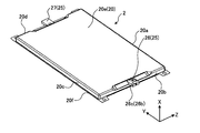
- FIG. 1 is a perspective view of the battery cell 2 of the assembled battery 1.
- the battery cell 2 includes a housing 20 and a pair of electrode portions 25.
- One of the electrode portions 25 is a positive electrode terminal 26, and the other is a negative electrode terminal 27.
- directions are defined for convenience as shown in each drawing.
- the X direction is along the thickness direction (height direction) of the battery cell 2
- the Y direction is along the longitudinal direction of the battery cell 2
- the Z direction is along the short side direction (width direction) of the battery cell 2.
- the X direction, the Y direction, and the Z direction are orthogonal to each other.
- the battery cell 2 is composed of, for example, a lithium ion secondary battery.
- the battery cell 2 may be another secondary battery such as a nickel metal hydride battery or nickel cadmium battery.
- a lithium ion secondary battery is a kind of non-aqueous electrolyte secondary battery, and lithium ions in the electrolyte are responsible for electrical conduction.
- the positive electrode material include lithium manganese composite oxide, lithium nickel composite oxide, lithium cobalt composite oxide, lithium nickel cobalt composite oxide, lithium manganese cobalt composite oxide, spinel type lithium manganese nickel composite oxide, and olivine.
- a lithium phosphorus oxide having a structure is used, and as the negative electrode material, for example, an oxide material such as lithium titanate (LTO), an oxide material such as niobium composite oxide, or the like is used.
- an oxide material such as lithium titanate (LTO), an oxide material such as niobium composite oxide, or the like is used.
- electrolyte for example, electrolyte solution
- lithium salt such as fluorine-type complex salt (for example, LiBF4, LiPF6), etc. were mix
- An organic solvent or the like may be used alone or in combination.
- the battery cell 2 is also referred to as a single battery or the like.
- the casing 20 of the battery cell 2 is configured in a flat rectangular parallelepiped shape that is thin in the X direction.
- the housing 20 has a plurality of wall portions 20a to 20f. Each of the wall portion 20e and the wall portion 20f extends along a direction (YZ plane) orthogonal to the X direction, and is provided in parallel to each other with an interval in the X direction.
- One of the walls 20e and 20f may be referred to as a bottom wall or a lower wall, and the other may be referred to as a top wall or an upper wall.
- the housing 20 is made of, for example, a relatively thin SUS.
- the wall portions 20a to 20d are located at the peripheral edge portion of the wall portion 20e and extend between the wall portion 20e and the wall portion 20f.
- Each of the wall portion 20a and the wall portion 20c extends along a direction (XY plane) orthogonal to the Z direction, and is provided in parallel to each other with an interval in the Z direction.
- the wall portions 20 a and 20 c are referred to as a side wall portion, a peripheral wall portion, and the like, and constitute two long side portions among the four side portions of the housing 20.
- the valve part for degassing can be provided in one of wall part 20a, 20c. The valve portion is opened when the pressure in the housing 20 becomes higher than the threshold, and reduces the pressure in the housing 20.
- both the wall portion 20b and the wall portion 20d extend along a direction (XZ plane) orthogonal to the Y direction, and are provided at intervals in the Y direction.
- the wall portions 20 b and 20 d are referred to as a side wall portion, a peripheral wall portion, and the like, and constitute two short side portions of the four side portions of the housing 20.
- One of the walls 20b and 20d is provided with a positive terminal 26, and the other is provided with a negative terminal 27.
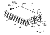
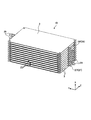
- FIG. 2 is a perspective view of the assembled battery 1
- FIG. 3 is a cross-sectional view taken along the line AA in FIG.
- the assembled battery 1 includes, for example, a plurality of battery cells 2, an insulating plate 3, and the like.
- positioning, etc. of each components, such as the battery cell 2 contained in the assembled battery 1 are not limited to what is disclosed by this embodiment.
- the assembled battery 1 may include a monitoring board for monitoring the voltage and temperature of the battery cell 2 and a control board for battery control.
- the assembled battery 1 is also referred to as a battery module, a battery unit, or the like.
- the plurality of battery cells 2 are arranged in the X direction with the outer surface 20i of each wall portion 20e facing the same direction (upward).
- the plurality of battery cells 2 are arranged so that the positive terminals 26 and the negative terminals 27 are alternately arranged in the direction along the X direction.
- the connection portions 22 between the positive electrode terminal 26 and the negative electrode terminal 27 are configured to be alternately arranged in one (left direction) and the other (right direction) in the Y direction.
- the X direction is an example of a first direction
- the Y direction is an example of a second direction.
- the insulating plate 3 has a rectangular shape extending along a direction (YZ plane) orthogonal to the X direction.
- the size of the insulating plate 3 is substantially the same as the size of the walls 20e and 20f.
- the insulating plates 3 are each positioned between two battery cells 2 adjacent in the X direction.
- the insulating plates 3 and the battery cells 2 are alternately stacked in the X direction.
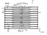
- the two battery cells 2 adjacent to each other in the X direction are mechanically connected to each other and electrically connected to each other by press-fitting of the male-female structure shown in FIG.
- the positive terminal 26 is provided with a protrusion 26c protruding in one direction (upward) in the X direction
- the negative terminal 27 is connectable to the protrusion 26c indented in one (upward) in the X direction.
- a recess 27d is provided.
- the protrusion 26c is an example of a male structure
- the recess 27d is an example of a female structure.
- the protrusion 26c can also be called a male connector or the like, and the recess 27d can also be called a female connector or the like.
- the male-female structure is not limited to this example.
- the positive electrode terminal 26 may be provided with a concave portion 27d
- the negative electrode terminal 27 may be provided with a protruding portion 26c.
- the positive terminal 26 includes, for example, a base portion 26a and a connection portion 26b provided with a protruding portion 26c.
- the negative electrode terminal 27 includes, for example, a base portion 27a and a connection portion 27b provided with a recess 27d.
- the base portions 26a and 27a and the connection portions 26b and 27b are integrated (coupled) with each other by welding or the like.
- the connection portions 26b and 27b are also referred to as connection terminals.
- the connecting portion 27b is provided with a protruding portion 27c protruding in the other direction (downward) in the X direction.
- the protruding portion 27c is, for example, a cylindrical shape along the protruding portion 26c.
- the recess 27d is provided in the cylinder of the protrusion 27c, and has an opening width (diameter) that is substantially the same as or slightly smaller than the diameter of the protrusion 26c.
- the protrusion part 26c is not limited to this example, For example, a solid cylindrical shape may be sufficient.
- each of the plurality of battery cells 2 is provided with the positive terminal 26 provided with the protruding portion 26c and the concave portion 27d having a shape that is fitted to the protruding portion 26c by press fitting. Negative electrode terminal 27.
- the plurality of battery cells 2 can be electrically connected more easily by the protruding portion 26c and the recessed portion 27d, and as a result, the assembled battery 1 is manufactured (assembled). Is easy to reduce.
- the protruding portion 26c and the recessed portion 27d extend along the X direction in which the plurality of battery cells 2 are arranged.
- the two battery cells 2 adjacent in the X direction can be more easily electrically connected to each other by the protrusion 26c and the recess 27d, and the plurality of battery cells 2 can be It can be more firmly integrated in the X direction.
- connection portions 22 by the protruding portions 26c and the recessed portions 27d are alternately arranged in one side and the other side in the Y direction.
- the plurality of battery cells 2 arranged along the X direction are relatively easily connected via the connection portion 22, and as a result, a series circuit including the plurality of battery cells 2 is relatively easy. Is obtained.
- the assembled battery 1A of the embodiment shown in FIGS. 4 to 6 has the same configuration as the assembled battery 1 of the first embodiment. Therefore, according to this embodiment, the same result (effect) based on the same configuration as that of the first embodiment can be obtained.
- the male connector 25c and the female connector 25d are provided on the positive electrode terminal 25A and the negative electrode terminal 25B, respectively. Is different.
- the male connector 25c is an example of a male structure
- the female connector 25d is an example of a female structure.
- the male connector 25c and the female connector 25d can also be referred to as flat connection terminals or the like.
- a connecting portion 25b having the same configuration is integrated (coupled) by welding or the like to the base portion 25a of the positive electrode terminal 25A and the negative electrode terminal 25B. That is, the connection part 25b of the positive electrode terminal 25A and the connection part 25b of the negative electrode terminal 25B are the same components.
- the male connector 25c and the female connector 25d protrude from the connection portion 25b in one direction in the Y direction, that is, on the side opposite to the battery cell 2A, and are aligned in the Z direction. Further, the positive terminal 25A and the negative terminal 25B are arranged so that the male connector 25c and the female connector 25d are rotationally symmetrical with each other.
- the connection part 25b is also referred to as a connection terminal or the like.
- the plurality of battery cells 2A are arranged in the Y direction.
- the plurality of battery cells 2A are arranged so that the positive electrode terminals 25A and the negative electrode terminals 25B are alternately arranged in the direction along the Y direction.
- two battery cells 2A adjacent in the Y direction are mechanically connected to each other and electrically connected by press-fitting of a pair of male connector 25c and female connector 25d.
- the Y direction is an example of a first direction.
- the positive terminal 25A and the negative terminal 25B include the male connector 25c and the female connector 25d, respectively.
- the plurality of battery cells 2A can be electrically connected more easily as in the first embodiment.
- the plurality of battery cells 2A can be integrated more firmly.
- this modification differs from the second embodiment in that a plurality of battery cells 2A are electrically connected via a conductive member 28 as shown in FIGS. ing.
- the conductive member 28 is an example of a wiring member.
- the conductive member 28 is also called a bus bar or the like.
- the conductive member 28 includes, for example, a base portion 28a, two male connectors 28c, and two female connectors 28d.
- the base portion 28a is configured in a strip shape extending along one direction (Z direction).
- a pair of a male connector 28c and a female connector 28d is provided at one end of the base portion 28a, and another pair of a male connector 28c and a female connector 28d is provided at the other end of the base portion 28a.
- the configuration (shape) of the male connector 28c and the female connector 28d is the same as the configuration (shape) of the male connector 25c and the female connector 25d (see FIG. 5) of the positive electrode terminal 25A (negative electrode terminal 25B).
- the plurality of battery cells 2A are arranged in the Z direction. Also, two battery cells 2A adjacent in the Z direction are electrically connected to each other via the conductive member 28 and mechanically connected.
- the assembled battery 1B can be configured, for example, by providing a plurality of pairs of battery cells 2A connected in parallel in the Z direction in the X direction and connecting them in series.
- the Z direction is an example of a first direction.
- the plurality of battery cells 2A are provided with the male connector 28c and the female connector 28d having the same configuration as the male connector 25c and the female connector 25d of the positive electrode terminal 25A (negative electrode terminal 25B). It is electrically connected through the conductive member 28.
- the plurality of battery cells 2A can be electrically connected more easily. Time and effort required for manufacturing (assembling) the assembled battery 1B is likely to be reduced.
- this modification is different from Modification 1 of the second embodiment in that, for example, as shown in FIG. 9, a plurality of battery cells 2A are arranged in the X direction. Further, the two battery cells 2A adjacent in the X direction are electrically connected to each other and mechanically connected via the conductive member 28A.
- the X direction is an example of a first direction
- the conductive member 28A is an example of a wiring member.
- the conductive member 28 ⁇ / b> A is configured in a substantially U shape that is open to one side in the Y direction, that is, to the battery cell 2 ⁇ / b> A side, as viewed in the Z direction.
- the conductive member 28A includes a pair of a male connector 28c and a female connector 28d positioned at one end in the X direction and arranged in the Z direction, and a male connector 28c and a female connector 28d positioned at the other end in the X direction and aligned in the Z direction. And a base portion 28a extending between the two pairs. According to this modification, the same effect as that of the conductive member 28 of Modification 1 of the second embodiment can be obtained by the conductive member 28A.
- the present invention is not limited to this.
- the positive terminal 25A (negative terminal) 25B), the male connector 25c and the female connector 25d of the positive electrode terminal 25A and the male connector 25c and the female connector 25d of the negative electrode terminal 25B are directly press-fitted by folding back the connecting portion 25b about the axis along the Z direction. You may connect.
- the assembled battery 1D of the embodiment shown in FIGS. 11 to 13 has the same configuration as the assembled battery 1 of the first embodiment. Therefore, according to this embodiment, the same result (effect) based on the same configuration as that of the first embodiment can be obtained.
- the positive terminal 26 is provided with a female connector 26 f and the negative terminal 27 is provided with a male connector 27 f. It is different.
- the male connector 27f is an example of a male structure
- the female connector 26f is an example of a female structure.
- the male connector 27f and the female connector 26f can also be referred to as a burrow terminal or the like.
- the male / female structure is not limited to this example.
- the male connector 27f may be provided on the positive terminal 26 and the female connector 26f may be provided on the negative terminal 27.
- the plurality of battery cells 2D are arranged in the X direction. Further, two battery cells 2D adjacent in the X direction are mechanically connected to each other via the conductive member 29 and are also electrically connected.
- the conductive member 29 includes, for example, a male connector 29c that can be connected to the female connector 26f by press-fitting, a female connector 29d that can be connected to the male connector 27f by press-fitting, a male connector 29c, and a female connector 29d. And a connecting portion 29a extending between the two.
- the conductive member 29 is an example of a wiring member.
- the conductive member 29 can also be referred to as a bus bar or the like. According to the present embodiment, the conductive member 29 can provide the same effects as those of the conductive member 28 of the first modification of the second embodiment.
- the assembled battery 1E of the embodiment shown in FIGS. 14 to 16 has the same configuration as the assembled battery 1 of the first embodiment. Therefore, according to this embodiment, the same result (effect) based on the same configuration as that of the first embodiment can be obtained.
- the battery cell 2 ⁇ / b> E is provided with a plurality of positive terminals 23 and negative terminals 24, which is different from the first embodiment.
- the number of positive electrode terminals 23 (negative electrode terminals 24) is not limited to three, and may be two or four or more, for example.
- the bus bar 30 includes, for example, a first member 31 and a second member 32.
- the first member 31 is an example of a first connection member
- the second member 32 is an example of a second connection member.
- the first member 31 is integrated (coupled) by welding or the like with, for example, one of the plurality of positive terminals 23 of two battery cells 2E adjacent in the X direction.
- the second member 32 is integrated (coupled) with the other plurality of negative terminals 24 of the two battery cells 2E adjacent in the X direction by welding or the like, for example.
- the first member 31 and the second member 32 are integrated (coupled) with each other by a nut 42 meshing with a bolt 41 penetrating in the Y direction.
- the bolt 41 and the nut 42 are an example of a coupler.
- one of the plurality of positive terminals 23 of the two battery cells 2 and the other plurality of negative terminals 24 are electrically connected via the bus bar 30.
- the plurality of battery cells 2E can be electrically connected to each other more easily. Can be connected.
- the bus bar 30 includes the first member 31 electrically connected to one of the plurality of positive terminals 23 of the two battery cells 2E, and the other plurality of negative terminals 24 to the electric power. And a first member 31 and a second member 32 electrically connected by bolts 41 and nuts 42. According to such a configuration, for example, the plurality of battery cells 2E are electrically connected more easily, more smoothly, or more accurately by the divided first member 31 and second member 32. be able to.
- first member 31 and the second member 32 are integrated (coupled) by the bolt 41 and the nut 42 is illustrated, but the present invention is not limited thereto. 17 may be integrated (coupled) by a coupling tool 43 such as a rivet or a screw.
- the assembled battery 1G of the embodiment shown in FIGS. 18 and 19 has the same configuration as the assembled battery 1E of the fourth embodiment. Therefore, also in this embodiment, the same result (effect) based on the same configuration as that of the fourth embodiment can be obtained.
- the point that the plurality of battery cells 2G are electrically connected via the bus bar 35 is different from the fourth embodiment. Yes.
- the bus bar 35 is provided with a narrow portion.
- Each of the positive electrode terminal 23 and the negative electrode terminal 24 includes a plurality of base portions (not shown) and connection portions 23b and 24b connectable to the bus bar 35.
- the connection parts 23b, 24b and the plurality of base parts are respectively integrated (coupled) by welding or the like.
- the connection portions 23b and 24b are also referred to as connection terminals.
- the female screw part 21 is provided in the connection parts 23b and 24b.
- the male screw portion of the screw 45 penetrating the bus bar 35 in the Y direction meshes with the female screw portion 21, the plurality of battery cells 2G are electrically connected to each other and mechanically connected.
- the screw 45 is an example of a coupling tool having conductivity.
Abstract
実施形態の組電池は、例えば、複数の電池セルを備える。複数の電池セルは、第一の方向に並び、それぞれ、雄構造または当該雄構造と圧入により装着される形状の雌構造のうち一方を有した正極端子と、雄構造および雌構造のうち他方を有した負極端子と、を有する。
Description
本発明の実施形態は、組電池および電池セルに関する。
従来、上壁部に電極部が設けられた金属缶タイプの電池セルと、電池セルを支持したホルダと、を備えた組電池、が知られている。
この種の組電池では、例えば、より不都合の少ない新規な構成が得られれば、好ましい。
上記の課題を解決するために、実施形態の組電池は、例えば、複数の電池セルを備える。複数の電池セルは、第一の方向に並び、それぞれ、雄構造または当該雄構造と圧入により装着される形状の雌構造のうち一方を有した正極端子と、雄構造および雌構造のうち他方を有した負極端子と、を有する。
以下、本発明の例示的な実施形態が開示される。以下に示される実施形態の構成、ならびに当該構成によってもたらされる作用および結果(効果)は、一例である。本発明は、以下の実施形態に開示される構成以外によっても実現可能である。また、本発明によれば、構成によって得られる種々の効果(派生的な効果も含む)のうち少なくとも一つが得られうる。
以下、実施形態を図面に基づき説明する。なお、以下に開示される複数の実施形態には、同様の構成要素が含まれる。よって、以下では、それら同様の構成要素には共通の符号が付与されるとともに、重複する説明が省略される。なお、本明細書では、序数は、部品や部材を区別するためだけに用いられており、順番や優先度を示すものではない。
(第1の実施形態)
図1は、組電池1の電池セル2の斜視図である。電池セル2は、筐体20と、一対の電極部25と、を有する。電極部25のうち一方は正極端子26であり、他方は負極端子27である。なお、以下の説明では、各図面に示されるように、便宜上、方向が定義されている。X方向は、電池セル2の厚さ方向(高さ方向)に沿い、Y方向は、電池セル2の長手方向に沿い、Z方向は、電池セル2の短手方向(幅方向)に沿う。X方向、Y方向、およびZ方向は、互いに直交している。
図1は、組電池1の電池セル2の斜視図である。電池セル2は、筐体20と、一対の電極部25と、を有する。電極部25のうち一方は正極端子26であり、他方は負極端子27である。なお、以下の説明では、各図面に示されるように、便宜上、方向が定義されている。X方向は、電池セル2の厚さ方向(高さ方向)に沿い、Y方向は、電池セル2の長手方向に沿い、Z方向は、電池セル2の短手方向(幅方向)に沿う。X方向、Y方向、およびZ方向は、互いに直交している。
電池セル2は、例えば、リチウムイオン二次電池等で構成されている。なお、電池セル2は、ニッケル水素電池や、ニッケルカドミウム電他等、他の二次電池であってもよい。リチウムイオン二次電池は、非水電解質二次電池の一種であり、電解質中のリチウムイオンが電気伝導を担う。正極材料としては、例えば、リチウムマンガン複合酸化物や、リチウムニッケル複合酸化物、リチウムコバルト複合酸化物、リチウムニッケルコバルト複合酸化物、リチウムマンガンコバルト複合酸化物、スピネル型リチウムマンガンニッケル複合酸化物、オリビン構造を有するリチウムリン酸化物等が用いられ、負極材料としては、例えば、チタン酸リチウム(LTO)等の酸化物系材料や、ニオブ複合酸化物等の酸化物材料等が用いられる。また、電解質(例えば、電解液)としては、フッ素系錯塩(例えばLiBF4、LiPF6)等のリチウム塩が配合された、例えば、炭酸エチレンや、炭酸プロピレン、炭酸ジエチル、炭酸エチルメチル、炭酸ジメチル等の有機溶媒等が単独であるいは複数混合されて用いられる。電池セル2は、単電池等とも称される。
図1に示されるように、電池セル2の筐体20は、X方向に薄い偏平な直方体状に構成されている。筐体20は、複数の壁部20a~20fを有する。壁部20eおよび壁部20fは、いずれも、X方向と直交する方向(YZ平面)に沿って延びており、X方向に間隔をあけて互いに平行に設けられている。壁部20e,20fのうち一方は、底壁部や下壁部等と称され、他方は、天壁部や上壁部等と称されうる。筐体20は、例えば比較的厚さの薄いSUSにより形成されている。
また、壁部20a~20dは、壁部20eの周縁部に位置され、当該壁部20eと壁部20fとの間に亘っている。壁部20aおよび壁部20cは、いずれも、Z方向と直交する方向(XY平面)に沿って延びており、Z方向に間隔をあけて互いに平行に設けられている。壁部20a,20cは、側壁部や周壁部等と称され、筐体20の四つの辺部のうち二つの長辺部を構成している。また、壁部20a,20cのうち一方には、ガス抜き用の弁部が設けられうる。弁部は、筐体20内の圧力が閾値よりも高くなった場合に開放され、当該筐体20内の圧力を低下させる。
また、壁部20bおよび壁部20dは、いずれも、Y方向と直交する方向(XZ平面)に沿って延びており、Y方向に互いに間隔をあけて設けられている。壁部20b,20dは、側壁部や周壁部等と称され、筐体20の四つの辺部のうち二つの短辺部を構成している。また、壁部20b,20dのうち一方には、正極端子26が設けられ、他方には、負極端子27が設けられている。
図2は、組電池1の斜視図であり、図3は、図2のA-A断面図である。図2,3に示されるように、組電池1は、例えば、複数の電池セル2や、絶縁板3等を備えている。なお、組電池1に含まれる電池セル2等の各部品の数や配置等は、本実施形態で開示されるものには限定されない。また、組電池1には、電池セル2の電圧や温度を監視するための監視基板や、電池制御のための制御基板等が含まれうる。組電池1は、電池モジュールや、電池ユニット等とも称される。
複数の電池セル2は、それぞれの壁部20eの外面20iが同じ方向(上方)を向いた姿勢で、X方向に並べられている。また、複数の電池セル2は、X方向に沿う方向において、正極端子26と負極端子27とが交互に配置されるように並べられている。このような構成により、本実施形態では、正極端子26と負極端子27との接続部位22が、Y方向の一方(左方向)と他方(右方向)とに交互に配置されるよう構成されている。X方向は、第一の方向の一例であり、Y方向は、第二の方向の一例である。
絶縁板3は、X方向と直交する方向(YZ平面)に沿って延びた長方形状に構成されている。絶縁板3の大きさは、壁部20e,20fの大きさと略同じである。絶縁板3は、それぞれ、X方向に隣接した二つの電池セル2の間に位置される。絶縁板3と電池セル2とは、X方向に交互に積み重ねられている。
そして、本実施形態では、X方向に隣接した二つの電池セル2同士が、図3に示される雄雌構造の圧入によって互いに機械的に接続されるとともに電気的にも接続されている。具体的には、正極端子26には、X方向の一方(上方)に突出した突出部26cが設けられ、負極端子27には、X方向の一方(上方)に凹み突出部26cと接続可能な凹部27dが設けられている。突出部26cは、雄構造の一例であり、凹部27dは、雌構造の一例である。突出部26cは、雄コネクタ等とも称され、凹部27dは、雌コネクタ等とも称されうる。なお、雄雌構造は、この例には限定されず、例えば、正極端子26に凹部27dが設けられ、負極端子27に突出部26cが設けられてもよい。
また、正極端子26は、例えば、ベース部26aと、突出部26cが設けられた接続部26bと、を含む。同様に、負極端子27は、例えば、ベース部27aと、凹部27dが設けられた接続部27bと、を含む。ベース部26a,27aと接続部26b,27bとは、それぞれ、溶接等によって互いに一体化(結合)されている。接続部26b,27bは、接続端子等とも称される。
また、接続部27bには、X方向の他方(下方)に突出した突出部27cが設けられている。突出部27cは、例えば、突出部26cに沿った円筒状である。凹部27dは、突出部27cの筒内に設けられ、突出部26cの直径と略同じかあるいは僅かに小さい開口幅(直径)を有している。なお、突出部26cは、この例には限定されず、例えば、中実の円柱状であってもよい。
以上のように、本実施形態では、例えば、複数の電池セル2は、それぞれ、突出部26cが設けられた正極端子26と、突出部26cと圧入により装着される形状の凹部27dが設けられた負極端子27と、を有する。このような構成によれば、例えば、突出部26cと凹部27dとによって、より簡単に複数の電池セル2を電気的に接続することができるようになり、ひいては組電池1の製造(組立作業)に要する手間が減りやすい。
また、本実施形態では、例えば、突出部26cと凹部27dとが複数の電池セル2が並ぶX方向に沿って延びている。このような構成によれば、例えば、突出部26cと凹部27dとによって、より簡単にX方向に隣接した二つの電池セル2同士を電気的に接続することができる上、複数の電池セル2をより強固にX方向に一体化することができる。
また、本実施形態では、例えば、X方向に並んだ複数の電池セル2の列において、突出部26cと凹部27dとによる接続部位22がY方向の一方と他方とに交互に配置されている。このような構成によれば、例えば、X方向に沿って並ぶ複数の電池セル2が、接続部位22を介して比較的簡単に接続され、ひいては複数の電池セル2による直列回路が、比較的容易に得られる。
(第2の実施形態)
図4~6に示される実施形態の組電池1Aは、上記第1の実施形態の組電池1と同様の構成を備えている。よって、本実施形態によっても、上記第1の実施形態と同様の構成に基づく同様の結果(効果)が得られる。
図4~6に示される実施形態の組電池1Aは、上記第1の実施形態の組電池1と同様の構成を備えている。よって、本実施形態によっても、上記第1の実施形態と同様の構成に基づく同様の結果(効果)が得られる。
ただし、本実施形態では、例えば、図4,5に示されるように、正極端子25Aおよび負極端子25Bのそれぞれに雄コネクタ25cおよび雌コネクタ25dが設けられている点が、上記第1の実施形態と相違している。雄コネクタ25cは、雄構造の一例であり、雌コネクタ25dは、雌構造の一例である。雄コネクタ25cおよび雌コネクタ25dは、平型接続端子等とも称されうる。
正極端子25Aおよび負極端子25Bのベース部25aには、それぞれ同様の構成の接続部25bが溶接等によって一体化(結合)されている。すなわち、正極端子25Aの接続部25bと負極端子25Bの接続部25bとは、互いに同一の部品である。雄コネクタ25cおよび雌コネクタ25dは、それぞれ、接続部25bからY方向の一方、すなわち電池セル2Aとは反対側に突出し、Z方向に並んでいる。また、正極端子25Aおよび負極端子25Bは、それぞれの雄コネクタ25cおよび雌コネクタ25dが互いに回転対称となるように配置されている。接続部25bは、接続端子等とも称される。
図6に示されるように、本実施形態では、複数の電池セル2Aは、Y方向に並べられている。また、複数の電池セル2Aは、Y方向に沿う方向において、正極端子25Aと負極端子25Bとが交互に配置されるように並べられている。また、Y方向に隣接した二つの電池セル2Aが、雄コネクタ25cおよび雌コネクタ25dのペア同士の圧入によって互いに機械的に接続されるとともに電気的にも接続されている。Y方向は、第一の方向の一例である。
以上のように、本実施形態では、例えば、正極端子25Aおよび負極端子25Bは、それぞれ、雄コネクタ25cおよび雌コネクタ25dを有している。このような構成によれば、例えば、雄コネクタ25cおよび雌コネクタ25dのペア同士の接続によって、上記第1の実施形態と同様に、より簡単に複数の電池セル2Aを電気的に接続することができるようになり、ひいては組電池1Aの製造(組立作業)に要する手間が減りやすい。また、複数の電池セル2Aをより強固に一体化することができる。
(第2の実施形態の変形例1)
図7,8に示される変形例の組電池1Bは、上記第2の実施形態の組電池1Aと同様の構成を備えている。よって、本変形例によっても、上記第2の実施形態と同様の構成に基づく同様の結果(効果)が得られる。
図7,8に示される変形例の組電池1Bは、上記第2の実施形態の組電池1Aと同様の構成を備えている。よって、本変形例によっても、上記第2の実施形態と同様の構成に基づく同様の結果(効果)が得られる。
ただし、本変形例では、例えば、図7,8に示されるように、複数の電池セル2Aが導電部材28を介して電気的に接続されている点が、上記第2の実施形態と相違している。導電部材28は、配線部材の一例である。導電部材28は、バスバー等とも称される。
図8に示されるように、導電部材28は、例えば、ベース部28aと、二つの雄コネクタ28cと、二つの雌コネクタ28dと、を有する。ベース部28aは、一方向(Z方向)に沿って延びた帯板状に構成されている。ベース部28aの一端部には、雄コネクタ28cおよび雌コネクタ28dのペアが設けられ、ベース部28aの他端部には、雄コネクタ28cおよび雌コネクタ28dの別のペアが設けられている。雄コネクタ28cおよび雌コネクタ28dの構成(形状)は、正極端子25A(負極端子25B)の雄コネクタ25cおよび雌コネクタ25d(図5参照)の構成(形状)と同じである。
図7に示されるように、本実施形態では、複数の電池セル2Aは、Z方向に並べられている。また、Z方向に隣接した二つの電池セル2Aが、導電部材28を介して互いに電気的に接続されるとともに機械的にも接続されている。組電池1Bは、例えば、Z方向に並列に接続された複数の電池セル2AがX方向に複数ペア設けられ、これらが直列に接続されること等によって構成されうる。Z方向は、第一の方向の一例である。
以上のように、本変形例では、例えば、複数の電池セル2Aが、正極端子25A(負極端子25B)の雄コネクタ25cおよび雌コネクタ25dと同じ構成の雄コネクタ28cおよび雌コネクタ28dが設けられた導電部材28を介して電気的に接続されている。このような構成によれば、例えば、雄コネクタ25c,28cと雌コネクタ25d,28dとの圧入による接続によって、より簡単に複数の電池セル2Aを電気的に接続することができるようになり、ひいては組電池1Bの製造(組立作業)に要する手間が減りやすい。
(第2の実施形態の変形例2)
図9,10に示される変形例の組電池1Cは、上記第2の実施形態の変形例1の組電池1Bと同様の構成を備えている。よって、本変形例によっても、上記第2の実施形態の変形例1と同様の構成に基づく同様の結果(効果)が得られる。
図9,10に示される変形例の組電池1Cは、上記第2の実施形態の変形例1の組電池1Bと同様の構成を備えている。よって、本変形例によっても、上記第2の実施形態の変形例1と同様の構成に基づく同様の結果(効果)が得られる。
ただし、本変形例では、例えば、図9に示されるように、複数の電池セル2AがX方向に並んでいる点が、上記第2の実施形態の変形例1と相違している。また、X方向に隣接した二つの電池セル2Aが、導電部材28Aを介して互いに電気的に接続されるとともに機械的にも接続されている。X方向は、第一の方向の一例であり、導電部材28Aは、配線部材の一例である。
図9,10に示されるように、導電部材28Aは、Z方向の視線では、Y方向の一方、すなわち電池セル2A側に開放された略U字状に構成されている。導電部材28Aは、X方向の一端部に位置されZ方向に並んだ雄コネクタ28cおよび雌コネクタ28dのペアと、X方向の他端部に位置されZ方向に並んだ雄コネクタ28cおよび雌コネクタ28dの別のペアと、二つのペアの間に渡ったベース部28aと、を有している。本変形例によれば、導電部材28Aによって、上記第2の実施形態の変形例1の導電部材28と同様の効果が得られる。
なお、本変形例では、X方向に隣接した二つの電池セル2Aが導電部材28Aを介して互いに接続された場合が例示されたが、これには限定されず、例えば、正極端子25A(負極端子25B)の接続部25bをZ方向に沿った軸回りに折り返すことにより、正極端子25Aの雄コネクタ25cおよび雌コネクタ25dと、負極端子25Bの雄コネクタ25cおよび雌コネクタ25dとをダイレクトに圧入して接続してもよい。
(第3の実施形態)
図11~13に示される実施形態の組電池1Dは、上記第1の実施形態の組電池1と同様の構成を備えている。よって、本実施形態によっても、上記第1の実施形態と同様の構成に基づく同様の結果(効果)が得られる。
図11~13に示される実施形態の組電池1Dは、上記第1の実施形態の組電池1と同様の構成を備えている。よって、本実施形態によっても、上記第1の実施形態と同様の構成に基づく同様の結果(効果)が得られる。
ただし、本実施形態では、例えば、図11に示されるように、正極端子26に雌コネクタ26fが設けられ、負極端子27に雄コネクタ27fが設けられている点が、上記第1の実施形態と相違している。雄コネクタ27fは、雄構造の一例であり、雌コネクタ26fは、雌構造の一例である。雄コネクタ27fおよび雌コネクタ26fは、ギボシ端子等とも称されうる。なお、雄雌構造は、この例には限定されず、例えば、正極端子26に雄コネクタ27fが設けられ、負極端子27に雌コネクタ26fが設けられてもよい。
図13に示されるように、複数の電池セル2Dは、X方向に並べられている。また、X方向に隣接した二つの電池セル2Dが、導電部材29を介して互いに機械的に接続されるとともに電気的にも接続されている。図12に示されるように、導電部材29は、例えば、雌コネクタ26fと圧入によって接続可能な雄コネクタ29cと、雄コネクタ27fと圧入によって接続可能な雌コネクタ29dと、雄コネクタ29cと雌コネクタ29dとの間に渡った接続部29aと、を有している。導電部材29は、配線部材の一例である。導電部材29は、バスバー等とも称されうる。本実施形態によれば、導電部材29によって、上記第2の実施形態の変形例1の導電部材28と同様の効果が得られる。
(第4の実施形態)
図14~16に示される実施形態の組電池1Eは、上記第1の実施形態の組電池1と同様の構成を備えている。よって、本実施形態によっても、上記第1の実施形態と同様の構成に基づく同様の結果(効果)が得られる。
図14~16に示される実施形態の組電池1Eは、上記第1の実施形態の組電池1と同様の構成を備えている。よって、本実施形態によっても、上記第1の実施形態と同様の構成に基づく同様の結果(効果)が得られる。
ただし、本実施形態では、例えば、図14に示されるように、電池セル2Eに複数の正極端子23および負極端子24が設けられている点が、上記第1の実施形態と相違している。なお、正極端子23(負極端子24)の数は、三つには限定されず、例えば、二つや、四つ以上であってもよい。
また、図15,16に示されるように、本実施形態では、X方向に隣接した二つの電池セル2E同士がバスバー30を介して互いに電気的に接続されている。バスバー30は、例えば、第一の部材31と、第二の部材32と、を有する。第一の部材31は、第一の接続部材の一例であり、第二の部材32は、第二の接続部材の一例である。
第一の部材31は、例えば、X方向に隣接した二つの電池セル2Eのうち一方の複数の正極端子23と溶接等によって一体化(結合)されている。また、第二の部材32は、例えば、X方向に隣接した二つの電池セル2Eのうち他方の複数の負極端子24と溶接等によって一体化(結合)されている。第一の部材31および第二の部材32は、それぞれをY方向に貫通したボルト41にナット42が噛み合うことによって互いに一体化(結合)される。ボルト41およびナット42は、結合具の一例である。
以上のように、本実施形態では、例えば、二つの電池セル2のうち一方の複数の正極端子23と、他方の複数の負極端子24とが、バスバー30を介して電気的に接続されている。このような構成によれば、例えば、バスバー30によって、電池セル2Eのそれぞれに複数の正極端子23(負極端子24)が設けられた構成において、より簡単に複数の電池セル2E同士を電気的に接続することができる。
また、本実施形態では、例えば、バスバー30は、二つの電池セル2Eのうち一方の複数の正極端子23と電気的に接続された第一の部材31と、他方の複数の負極端子24と電気的に接続され第一の部材31とボルト41およびナット42によって電気的に接続された第二の部材32と、を含む。このような構成によれば、例えば、分割された第一の部材31および第二の部材32によって、複数の電池セル2Eを、より容易に、より円滑に、あるいはより精度よく電気的に接続することができる。
なお、本実施形態では、第一の部材31と第二の部材32とがボルト41およびナット42によって一体化(結合)された場合が例示されたが、これには限定されず、例えば、図17に示される変形例1のように、リベットあるいはねじ等の結合具43によって一体化(結合)されてもよい。
(第5の実施形態)
図18,19に示される実施形態の組電池1Gは、上記第4の実施形態の組電池1Eと同様の構成を備えている。よって、本実施形態によっても、上記第4の実施形態と同様の構成に基づく同様の結果(効果)が得られる。
図18,19に示される実施形態の組電池1Gは、上記第4の実施形態の組電池1Eと同様の構成を備えている。よって、本実施形態によっても、上記第4の実施形態と同様の構成に基づく同様の結果(効果)が得られる。
ただし、本実施形態では、例えば、図18,19に示されるように、複数の電池セル2Gがバスバー35を介して電気的に接続されている点が、上記第4の実施形態と相違している。バスバー35には、狭隘部が設けられている。
正極端子23および負極端子24は、それぞれ、複数のベース部(不図示)と、バスバー35と接続可能な接続部23b,24bと、を含む。接続部23b,24bと複数のベース部とは、それぞれ、溶接等によって互いに一体化(結合)されている。接続部23b,24bは、接続端子等とも称される。
また、接続部23b,24bには、雌ネジ部21が設けられている。雌ネジ部21に、バスバー35をY方向に貫通したねじ45の雄ネジ部が噛み合うことによって、複数の電池セル2Gが互いに電気的に接続されるとともに機械的にも接続される。ねじ45は、導電性を有した結合具の一例である。
以上のような複数の実施形態の組電池1~1G、および電池セル2~2Gによって、例えば、大電流充放電および、製造時のねじ止めトルクに対する耐性を向上することができる。
以上、本発明の実施形態を例示したが、上記実施形態はあくまで一例であって、発明の範囲を限定することは意図していない。上記実施形態は、その他の様々な形態で実施されることが可能であり、発明の要旨を逸脱しない範囲で、種々の省略、置き換え、組み合わせ、変更を行うことができる。上記実施形態は、発明の範囲や要旨に含まれるとともに、請求の範囲に記載された発明とその均等の範囲に含まれる。本発明は、上記実施形態に開示される構成以外によっても実現可能であるとともに、基本的な構成(技術的特徴)によって得られる種々の効果(派生的な効果も含む)を得ることが可能である。また、各構成要素のスペック(構造や、種類、方向、形状、大きさ、長さ、幅、厚さ、高さ、数、配置、位置、材質等)は、適宜に変更して実施することができる。
Claims (8)
- 第一の方向に並んだ複数の電池セルを備えた組電池であって、
前記複数の電池セルは、それぞれ、雄構造または当該雄構造と圧入により装着される形状の雌構造のうち一方を有した正極端子と、前記雄構造および前記雌構造のうち他方を有した負極端子と、を有した、組電池。 - 前記雄構造は、前記第一の方向の一方に突出し、前記雌構造は、前記第一の方向の一方に凹み、
前記第一の方向に並んだ前記複数の電池セルの列において、前記第一の方向に隣接した二つの電池セルのうち一方の前記正極端子と、当該二つの電池セルのうち他方の前記負極端子とが、前記雄構造と前記雌構造との圧入によって電気的に接続された、請求項1に記載の組電池。 - 前記複数の電池セルのそれぞれにおいて、前記正極端子は前記第一の方向と交差する第二の方向の一端に設けられ、前記負極端子は前記第二の方向の他端に設けられ、
前記第一の方向に並んだ前記複数の電池セルの列において、前記第一の方向に隣接した二つの電池セルのうち一方の前記正極端子と当該二つの電池セルのうち他方の前記負極端子とが前記雄構造と前記雌構造との圧入によって電気的に接続された接続部位が、前記第二の方向の一方と他方とに交互に配置された、請求項2に記載の組電池。 - 前記第一の方向に並んだ前記複数の電池セルの列において、前記第一の方向に隣接した二つの電池セルのうち一方の前記正極端子と、当該二つの電池セルのうち他方の前記負極端子とが、前記雄構造と前記雌構造とを有した配線部材を介して電気的に接続された、請求項1に記載の組電池。
- 前記正極端子および前記負極端子には、それぞれ、前記雄構造および前記雌構造が設けられた、請求項1に記載の組電池。
- 第一の方向に並んだ複数の電池セルを備えた組電池であって、
前記複数の電池セルは、それぞれ、複数の正極端子と、複数の負極端子と、を有し、
前記第一の方向に並んだ前記複数の電池セルの列において、前記第一の方向に隣接した二つの電池セルのうち一方の前記複数の正極端子と、当該二つの電池セルのうち他方の前記複数の負極端子とが、バスバーを介して電気的に接続された、組電池。 - 前記バスバーは、前記第一の方向に隣接した二つの電池セルのうち一方の前記複数の正極端子と電気的に接続された第一接続部材と、当該二つの電池セルのうち他方の前記複数の負極端子と電気的に接続され前記第一接続部材と結合具によって接続された第二接続部材と、を含む、請求項6に記載の組電池。
- 請求項1~7のうちいずれか一つに記載の組電池に用いられる電池セル。
Priority Applications (3)
| Application Number | Priority Date | Filing Date | Title |
|---|---|---|---|
| CN201780006215.6A CN108475758A (zh) | 2016-05-30 | 2017-05-30 | 电池组及电池单元 |
| EP17806694.0A EP3467905A4 (en) | 2016-05-30 | 2017-05-30 | BATTERY PACK AND BATTERY CELL |
| US16/305,240 US20200083514A1 (en) | 2016-05-30 | 2017-05-30 | Battery pack and battery cell |
Applications Claiming Priority (2)
| Application Number | Priority Date | Filing Date | Title |
|---|---|---|---|
| JP2016107902A JP2017216088A (ja) | 2016-05-30 | 2016-05-30 | 組電池 |
| JP2016-107902 | 2016-05-30 |
Publications (1)
| Publication Number | Publication Date |
|---|---|
| WO2017209141A1 true WO2017209141A1 (ja) | 2017-12-07 |
Family
ID=60477822
Family Applications (1)
| Application Number | Title | Priority Date | Filing Date |
|---|---|---|---|
| PCT/JP2017/020140 WO2017209141A1 (ja) | 2016-05-30 | 2017-05-30 | 組電池および電池セル |
Country Status (5)
| Country | Link |
|---|---|
| US (1) | US20200083514A1 (ja) |
| EP (1) | EP3467905A4 (ja) |
| JP (1) | JP2017216088A (ja) |
| CN (1) | CN108475758A (ja) |
| WO (1) | WO2017209141A1 (ja) |
Cited By (2)
| Publication number | Priority date | Publication date | Assignee | Title |
|---|---|---|---|---|
| CN111433938A (zh) * | 2018-07-03 | 2020-07-17 | 株式会社Lg化学 | 电池模块、包括该电池模块的电池组和包括该电池组的车辆 |
| WO2022215342A1 (ja) * | 2021-04-09 | 2022-10-13 | 昭和電工パッケージング株式会社 | 蓄電モジュールおよびその積層構造 |
Families Citing this family (5)
| Publication number | Priority date | Publication date | Assignee | Title |
|---|---|---|---|---|
| JP7224903B2 (ja) * | 2018-12-26 | 2023-02-20 | 株式会社東芝 | 電池、電池アセンブリ、及び、電池モジュール |
| US11121408B2 (en) | 2019-03-14 | 2021-09-14 | Medtronic, Inc. | Lithium-ion battery |
| SE545544C2 (en) * | 2021-03-04 | 2023-10-17 | Scania Cv Ab | An electric battery cell unit and an electric battery arrangement |
| CN115347333A (zh) * | 2021-05-14 | 2022-11-15 | 中创新航科技股份有限公司 | 电池及电池组 |
| WO2023065366A1 (zh) * | 2021-10-22 | 2023-04-27 | 宁德时代新能源科技股份有限公司 | 电池、用电设备、制备电池单体的方法和设备 |
Citations (8)
| Publication number | Priority date | Publication date | Assignee | Title |
|---|---|---|---|---|
| JP2006196449A (ja) * | 2004-12-14 | 2006-07-27 | Toyota Motor Corp | 組電池 |
| JP2010080411A (ja) * | 2008-09-29 | 2010-04-08 | Beans You Inc | 電池及び電池の接続方法 |
| US20100216008A1 (en) * | 2009-02-26 | 2010-08-26 | Jihyoung Yoon | Secondary battery module |
| JP2011071053A (ja) * | 2009-09-28 | 2011-04-07 | Hitachi Vehicle Energy Ltd | 扁平角型電池および組電池 |
| JP2011150860A (ja) * | 2010-01-20 | 2011-08-04 | Sanyo Electric Co Ltd | 電源装置及びこれを備える車両 |
| JP2012059698A (ja) * | 2010-09-10 | 2012-03-22 | Sb Limotive Co Ltd | バッテリ及びこれを利用したバッテリパック |
| JP2012178271A (ja) * | 2011-02-25 | 2012-09-13 | Sanyo Electric Co Ltd | 組電池 |
| JP2015509279A (ja) * | 2013-01-03 | 2015-03-26 | エルジー・ケム・リミテッド | ケーブル型二次電池 |
Family Cites Families (11)
| Publication number | Priority date | Publication date | Assignee | Title |
|---|---|---|---|---|
| JPH08222201A (ja) * | 1995-02-14 | 1996-08-30 | Toyota Autom Loom Works Ltd | 電 池 |
| JP2001135358A (ja) * | 1999-08-24 | 2001-05-18 | Toyota Central Res & Dev Lab Inc | 密閉二次電池 |
| JP2001216950A (ja) * | 2000-02-02 | 2001-08-10 | Sony Corp | チップ型電池及び組電池装置 |
| EP2352185A1 (en) * | 2003-10-28 | 2011-08-03 | Johnson Controls Techonology Company | Battery container with improved heat dissipation |
| US20060127754A1 (en) * | 2004-12-14 | 2006-06-15 | Toyota Jidosha Kabushiki Kaisha. | Battery pack |
| KR100684847B1 (ko) * | 2005-05-17 | 2007-02-20 | 삼성에스디아이 주식회사 | 이차 전지 모듈 |
| JP5256589B2 (ja) * | 2006-07-07 | 2013-08-07 | 日本電気株式会社 | フィルム外装電池が複数隣接して配置された組電池 |
| KR101024635B1 (ko) * | 2008-12-29 | 2011-03-25 | 경상대학교산학협력단 | 실 형태 전지 및 이를 연결하기 위한 커넥터 |
| DE102009057368A1 (de) * | 2009-12-08 | 2011-06-09 | Li-Tec Battery Gmbh | Elektrochemischer Energiespeicher und Anordnung einer Mehrzahl solcher elektrochemischen Energiespeicher |
| JP2015099647A (ja) * | 2013-11-18 | 2015-05-28 | 本田技研工業株式会社 | 蓄電モジュールおよび蓄電セル |
| FR3017998B1 (fr) * | 2014-02-26 | 2017-09-29 | Commissariat Energie Atomique | Cellule de stockage d'energie electrique comportant au moins un element male et un element femelle, munis d'interfaces de connexion electrique |
-
2016
- 2016-05-30 JP JP2016107902A patent/JP2017216088A/ja active Pending
-
2017
- 2017-05-30 CN CN201780006215.6A patent/CN108475758A/zh not_active Withdrawn
- 2017-05-30 US US16/305,240 patent/US20200083514A1/en not_active Abandoned
- 2017-05-30 EP EP17806694.0A patent/EP3467905A4/en not_active Withdrawn
- 2017-05-30 WO PCT/JP2017/020140 patent/WO2017209141A1/ja unknown
Patent Citations (8)
| Publication number | Priority date | Publication date | Assignee | Title |
|---|---|---|---|---|
| JP2006196449A (ja) * | 2004-12-14 | 2006-07-27 | Toyota Motor Corp | 組電池 |
| JP2010080411A (ja) * | 2008-09-29 | 2010-04-08 | Beans You Inc | 電池及び電池の接続方法 |
| US20100216008A1 (en) * | 2009-02-26 | 2010-08-26 | Jihyoung Yoon | Secondary battery module |
| JP2011071053A (ja) * | 2009-09-28 | 2011-04-07 | Hitachi Vehicle Energy Ltd | 扁平角型電池および組電池 |
| JP2011150860A (ja) * | 2010-01-20 | 2011-08-04 | Sanyo Electric Co Ltd | 電源装置及びこれを備える車両 |
| JP2012059698A (ja) * | 2010-09-10 | 2012-03-22 | Sb Limotive Co Ltd | バッテリ及びこれを利用したバッテリパック |
| JP2012178271A (ja) * | 2011-02-25 | 2012-09-13 | Sanyo Electric Co Ltd | 組電池 |
| JP2015509279A (ja) * | 2013-01-03 | 2015-03-26 | エルジー・ケム・リミテッド | ケーブル型二次電池 |
Non-Patent Citations (1)
| Title |
|---|
| See also references of EP3467905A4 * |
Cited By (6)
| Publication number | Priority date | Publication date | Assignee | Title |
|---|---|---|---|---|
| CN111433938A (zh) * | 2018-07-03 | 2020-07-17 | 株式会社Lg化学 | 电池模块、包括该电池模块的电池组和包括该电池组的车辆 |
| JP2021501448A (ja) * | 2018-07-03 | 2021-01-14 | エルジー・ケム・リミテッド | バッテリーモジュール、これを含むバッテリーパック及びこのバッテリーパックを含む自動車 |
| JP7083897B2 (ja) | 2018-07-03 | 2022-06-13 | エルジー エナジー ソリューション リミテッド | バッテリーモジュール、これを含むバッテリーパック及びこのバッテリーパックを含む自動車 |
| US11456502B2 (en) | 2018-07-03 | 2022-09-27 | Lg Energy Solution, Ltd. | Battery module, battery pack comprising same battery module, and vehicle comprising same battery pack |
| CN111433938B (zh) * | 2018-07-03 | 2023-01-13 | 株式会社Lg新能源 | 电池模块、组装该电池模块的方法、包括该电池模块的电池组和包括该电池组的车辆 |
| WO2022215342A1 (ja) * | 2021-04-09 | 2022-10-13 | 昭和電工パッケージング株式会社 | 蓄電モジュールおよびその積層構造 |
Also Published As
| Publication number | Publication date |
|---|---|
| US20200083514A1 (en) | 2020-03-12 |
| CN108475758A (zh) | 2018-08-31 |
| EP3467905A4 (en) | 2020-01-08 |
| JP2017216088A (ja) | 2017-12-07 |
| EP3467905A1 (en) | 2019-04-10 |
Similar Documents
| Publication | Publication Date | Title |
|---|---|---|
| WO2017209141A1 (ja) | 組電池および電池セル | |
| US9627151B2 (en) | Electrical storage module | |
| US10211434B2 (en) | Battery pack | |
| US20160006006A1 (en) | Battery module | |
| JP5345648B2 (ja) | 2次電池および電池モジュール | |
| KR101446148B1 (ko) | 자동차용 배터리 팩에 포함되는 배터리 모듈 집합체 | |
| US20150325824A1 (en) | Battery block, battery module, and battery block holder | |
| KR101041154B1 (ko) | 이차전지 및 그 모듈 | |
| US9526187B2 (en) | Wiring module | |
| JP6256326B2 (ja) | 検知モジュール | |
| CN108780872B (zh) | 电池和用于制造电池的方法 | |
| WO2014019772A1 (de) | Batteriemodul sowie batterie und kraftfahrzeug umfassend ein solches | |
| CN109478629B (zh) | 布线模块 | |
| US20200227699A1 (en) | Battery module | |
| JP2016207584A (ja) | 組電池および導電部材 | |
| EP3496179B1 (en) | Connector for a battery pack | |
| JP5500364B2 (ja) | 電池接続アセンブリ | |
| US11502361B2 (en) | Energy storage apparatus | |
| JP2012248513A (ja) | 電池配線モジュール | |
| JP6670331B2 (ja) | 複数のサブモジュールを有するバッテリモジュール | |
| KR20090007337A (ko) | 소프트 패키지 리튬이온 파워 배터리 모듈 | |
| JP2015133289A (ja) | 電池モジュール及び電池モジュール用のホルダ | |
| JP2014179197A (ja) | 二次電池の接続構造およびこれを備えた二次電池装置 | |
| JP6134209B2 (ja) | 電池パック | |
| WO2011102344A1 (ja) | 電池モジュール用電極構成体 |
Legal Events
| Date | Code | Title | Description |
|---|---|---|---|
| NENP | Non-entry into the national phase |
Ref country code: DE |
|
| 121 | Ep: the epo has been informed by wipo that ep was designated in this application |
Ref document number: 17806694 Country of ref document: EP Kind code of ref document: A1 |
|
| ENP | Entry into the national phase |
Ref document number: 2017806694 Country of ref document: EP Effective date: 20190102 |