WO2017208611A1 - 車載用サーキュレータ - Google Patents
車載用サーキュレータ Download PDFInfo
- Publication number
- WO2017208611A1 WO2017208611A1 PCT/JP2017/013919 JP2017013919W WO2017208611A1 WO 2017208611 A1 WO2017208611 A1 WO 2017208611A1 JP 2017013919 W JP2017013919 W JP 2017013919W WO 2017208611 A1 WO2017208611 A1 WO 2017208611A1
- Authority
- WO
- WIPO (PCT)
- Prior art keywords
- air
- flow
- opening
- vehicle
- flap
- Prior art date
- Legal status (The legal status is an assumption and is not a legal conclusion. Google has not performed a legal analysis and makes no representation as to the accuracy of the status listed.)
- Ceased
Links
Images






Classifications
-
- B—PERFORMING OPERATIONS; TRANSPORTING
- B60—VEHICLES IN GENERAL
- B60H—ARRANGEMENTS OF HEATING, COOLING, VENTILATING OR OTHER AIR-TREATING DEVICES SPECIALLY ADAPTED FOR PASSENGER OR GOODS SPACES OF VEHICLES
- B60H1/00—Heating, cooling or ventilating devices
-
- B—PERFORMING OPERATIONS; TRANSPORTING
- B60—VEHICLES IN GENERAL
- B60H—ARRANGEMENTS OF HEATING, COOLING, VENTILATING OR OTHER AIR-TREATING DEVICES SPECIALLY ADAPTED FOR PASSENGER OR GOODS SPACES OF VEHICLES
- B60H1/00—Heating, cooling or ventilating devices
- B60H1/24—Ventilating devices where the heating or cooling is irrelevant
-
- B—PERFORMING OPERATIONS; TRANSPORTING
- B60—VEHICLES IN GENERAL
- B60H—ARRANGEMENTS OF HEATING, COOLING, VENTILATING OR OTHER AIR-TREATING DEVICES SPECIALLY ADAPTED FOR PASSENGER OR GOODS SPACES OF VEHICLES
- B60H1/00—Heating, cooling or ventilating devices
- B60H1/34—Nozzles; Air-diffusers
Definitions
- This disclosure relates to an in-vehicle circulator provided on the ceiling of a vehicle.
- an air-conditioning air outlet in a vehicle air conditioner is provided in a front portion of a passenger compartment, specifically, a front panel.
- the conditioned air blown from the front side part easily reaches the driver's seat and the front passenger seat, and hardly reaches the rear seat. For this reason, especially in a large vehicle having three rows of seats, a rear cooler that blows conditioned air toward the rear seat may be provided on the ceiling.
- the rear cooler incorporates an evaporator or the like for cooling the air, it is difficult to make the shape thin. As a result of an increase in the amount of protrusion of the rear cooler directed downward from the ceiling, there is a problem that the passenger compartment becomes narrow.
- Patent Document 1 describes an in-vehicle circulator provided on the ceiling of a vehicle.
- the in-vehicle circulator is a device that sucks the conditioned air blown from the front side portion of the passenger compartment and blows the conditioned air toward the rear side so that the conditioned air reaches the rear seat.
- Such an in-vehicle circulator does not need to accommodate an air-conditioning mechanism such as an evaporator inside, and thus can be made thinner than a rear cooler.
- the in-vehicle circulator be configured to blow out air in a plurality of directions. For example, if the configuration is such that air can be blown out toward each of the direction toward the second row of seats and the direction toward the third row of seats on the rear side, each of the seats is comfortable. Can be maintained in the environment.
- An object of the present disclosure is to provide an in-vehicle circulator capable of preventing a phenomenon in which respective air flows are attracted to each other when air is blown out in a plurality of directions on the rear side.
- An in-vehicle circulator is an in-vehicle circulator provided on a ceiling of a vehicle, wherein an inhalation portion in which a first opening for inhaling air in a vehicle interior is formed, and air sucked from the first opening And a blow-out part in which a second opening for blowing out toward the rear side of the vehicle is provided, and a fan for sending air from the first opening toward the second opening.
- the in-vehicle circulator is provided with a separation unit that separates the flow of air blown from the second opening into a first flow and a second flow that are separated from each other.
- the air flow blown from the second opening is separated into the first flow and the second flow by the separation unit. Further, the first flow and the second flow are separated from each other. For this reason, the phenomenon in which the first flow and the second flow are attracted to each other is prevented. Then, if the configuration is such that the direction of the flow direction of the air blown out as the first flow and the flow direction of the air blown out as the second flow can be adjusted by, for example, plate-shaped flaps, Air can be made to reach an appropriate position in the passenger compartment.
- an in-vehicle circulator capable of preventing a phenomenon in which respective air flows are attracted to each other when air is blown out in a plurality of directions on the rear side.
- FIG. 1 is a diagram for explaining the function of the in-vehicle circulator.
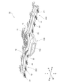
- FIG. 2 is a perspective view showing the overall structure of the in-vehicle circulator according to this embodiment.
- FIG. 3 is a perspective view showing the overall structure of the in-vehicle circulator according to this embodiment.
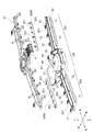
- 4 is an exploded view of the in-vehicle circulator shown in FIG.
- FIG. 5 is a sectional view showing the internal structure of the in-vehicle circulator shown in FIG. 2 in a top view.
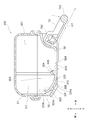
- FIG. 6 is a cross-sectional view of the arm portion in VII-VII in FIG.
- FIG. 7 is a cross-sectional view showing a state in which the angle of the flap is changed from FIG.
- FIG. 1 is a diagram for explaining the function of the in-vehicle circulator.
- FIG. 2 is a perspective view showing the overall structure of the in-vehicle circulator according to this embodiment.
- FIG. 3 is a perspective
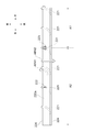
- FIG. 8 is a view showing the shape of the guide plate in a bottom view.
- FIG. 9 is a perspective view showing the shape of the separation portion.
- FIG. 10 is a diagram schematically showing the flow direction of the air blown out along the guide plate.
- FIG. 11 is a diagram showing a flow of air in the passenger compartment as viewed from above.
- FIG. 1 schematically shows a vehicle interior of a vehicle 800 provided with the in-vehicle circulator 10 according to the present embodiment.
- the vehicle 800 is provided with a front passenger seat 822, a second row seat 830, and a third row seat 840.
- a driver's seat 821 (not shown in FIG. 1; see FIG. 11) is provided at a position on the back side of the front surface of the passenger seat 822.
- a front panel 810 containing a vehicle air conditioner (not shown) is provided further forward of the driver seat 821 and the passenger seat 822.
- the conditioned air from the vehicle air conditioner is blown out from an opening 813 formed in the upper surface portion of the front panel 810, an opening 811 provided in a portion of the front panel 810 facing the driver's seat 821, and the like.
- FIG. 1 the flow of the conditioned air blown upward from the opening 813 toward the ceiling 802 along the windshield 801 of the vehicle 800 is indicated by arrows.
- the in-vehicle circulator 10 is attached to a position on the ceiling 802 that is behind the driver seat 821 and the passenger seat 822 and slightly forward from the seat 830.
- the in-vehicle circulator 10 is configured as a device that sucks in the conditioned air blown from the opening 813 on the front side and blows it out toward the rear side.
- the conditioned air can reach the seat 830 and the seat 840 where the conditioned air is difficult to reach, and the entire interior of the vehicle can be kept comfortable.
- the flow of air blown out from the in-vehicle circulator 10 to the rear side is indicated by an arrow AR1.
- the air present on the lower side of the in-vehicle circulator 10 is attracted to the flow indicated by the arrow AR1 due to the so-called Coanda effect, and then merges with the flow and travels backward.
- the air flow attracted in this way is indicated by an arrow AR2.
- the in-vehicle circulator 10 can cause air having a comfortable temperature to reach the seat 830 and the seat 840 with a sufficient air volume by generating such an air flow.
- the in-vehicle circulator 10 has a main body portion 100 and a pair of arm portions 200.
- the main body 100 is a portion located at the center in the left-right direction of the vehicle 800 when the in-vehicle circulator 10 is attached to the ceiling 802.
- a rectangular opening 110 is formed on the front side of the main body 100.
- the opening 110 is an opening for sucking in air in the vehicle interior, particularly conditioned air from the vehicle air conditioner, and corresponds to the “first opening” in the present embodiment.
- the main body 100 in which the opening 110 is formed corresponds to a “suction part” in the present embodiment.
- the opening 110 is formed toward the front side of the vehicle 800 and is formed so as to cover almost the entire front side surface of the main body 100. As a result, the opening 110 is formed at a center position in the left-right direction of the vehicle 800. Further, the width of the opening 110 is narrower than the width in the left-right direction in the vehicle interior. In other words, the opening 110 is not formed over the entire width direction of the passenger compartment, but is formed only in a partial region in the width direction.
- a fan 60 (see FIG. 4) not shown in FIG. 2 is provided inside the main body 100.
- the fan 60 is a so-called sirocco fan.
- the fan 60 generates air flow sucked from the opening 110 and air flow blown from the opening 210 by sending air from the opening 110 toward the opening 210 described later.
- the arm part 200 is a part that blows out air sucked from the opening 110 of the main body part 100 toward the rear side of the vehicle 800, and is provided on both the left and right sides of the main body part 100. That is, the pair of arm portions 200 are provided so as to be aligned along the left-right direction of the vehicle 800 with the main body portion 100 interposed therebetween.
- the left arm 200 extends from the left side surface of the main body 100 to a position near the left end of the ceiling 802.
- the right arm portion 200 extends from the right side surface of the main body portion 100 to a position near the right end of the ceiling 802. As shown in FIG.
- each arm part 200 is slightly different only in the vicinity of the connection part with the main body part 100, but the main part 100 is sandwiched between most other parts. It is almost symmetrical. For this reason, in the following description, a common reference numeral is assigned to each part of the arm part 200, and the configuration of each arm part 200 will be described.
- An opening 210 is formed on the lower surface side of each arm part 200.
- the opening 210 is an opening formed as an outlet for air blown toward the rear side of the vehicle 800, and corresponds to the “second opening” in the present embodiment.
- the arm part 200 in which the opening 210 is formed corresponds to a “blowing part” in the present embodiment.
- the opening 210 is formed in a slit shape whose longitudinal direction is along the longitudinal direction of the arm portion 200 (that is, the left-right direction of the vehicle 800). The air sucked from the opening 110 passes through the inside of the main body portion 100 and the inside of the arm portion 200, and then blows out from the entire opening 210 toward the rear side of the vehicle 800.
- a flap 71 and a flap 72 are provided in a portion of the arm portion 200 on the rear side of the opening 210, that is, on the downstream side of the opening 210 along the air flow direction.
- the flap 71 and the flap 72 are plate-like members for adjusting the flow direction of the air blown out from the opening 210.
- the flap 71 and the flap 72 are arranged in a line along the direction in which the opening 210 extends so as to cover the entire range of the downstream portion of the opening 210.
- An occupant of vehicle 800 can adjust the direction in which the air blown out from opening 210 is directed by manually changing the inclination angles of flap 71 and flap 72.
- a fixed portion 11 that protrudes further toward the rear side is formed on the rear side portion of the main body portion 100.
- a fixed portion 12 that protrudes further toward the front side is formed on the front side portion of the arm portion 200.
- fixed portions 13 that protrude toward the direction in which the arm portion 200 extends are formed on both side surfaces of the main body portion 100 and on the front side of the arm portion 200.
- These five fixed parts are parts that are directly fixed to the ceiling 802 when the in-vehicle circulator 10 is attached to the vehicle 800.
- a bolt (not shown) is inserted into the fixed portion 11 and the like from below.
- the in-vehicle circulator 10 is fixed to the ceiling 802 by fastening the bolt.
- the in-vehicle circulator 10 is configured by combining the upper case 51 and the lower case 52 so that the main body 100 and the pair of arms 200 are formed integrally.
- both the upper case 51 and the lower case 52 are formed of resin, and these are fastened and fixed by screws (not shown).
- it may replace with such an aspect and the aspect that the upper case 51 and the lower case 52 are mutually fixed by clip type fitting, without using a screw may be sufficient.
- the air sucked from the opening 110 by the operation of the fan 60 is sucked from the lower side by the fan 60 and then released from the side surface of the fan 60 to the surroundings.
- the fan 60 is accommodated in a space 111 formed on the upper side of a flow path extending from the opening 110 toward the rear side.
- a space 201 is formed in the arm portion 200 over the entire length of the arm portion 200, and the space 111 and the space 201 are connected to each other. For this reason, the air discharged from the side surface of the fan 60 flows into the space 201 from the space 111 and flows along the longitudinal direction of the space 201 (that is, toward the outside in the left-right direction of the vehicle 800).
- a guide plate 220 is accommodated in the space 201 of the arm 200. As shown in FIG. 4, the guide plate 220 is a plate-like member having a rectangular top view, and is formed of resin in this embodiment. The guide plate 220 is formed as a separate member from the lower case 52, and is attached to the lower case 52 from above the space 201.
- FIG. 6 shows a cross section when the arm 200 is cut at the position VII-VII in FIG.
- a protrusion 526 that protrudes upward is formed on the side of the bottom plate 524 of the lower case 52 that is the front end.
- a hook 224 is formed on the side of the guide plate 220 that is the rear end.
- the guide plate 220 is attached to the lower case 52 with the hook 224 fitted to the protrusion 526, and the lower surface thereof is smoothly connected to the lower surface 525 of the bottom plate 524.
- a portion of the guide plate 220 on the front side of the hook 224 is inclined with respect to the horizontal plane so as to go upward as it goes to the front side.
- a guide portion 523 is formed on the front side portion of the lower case 52.
- the guide portion 523 is a plate-like portion that extends downward, and is inclined with respect to the horizontal plane so as to go downward as it goes rearward.
- a part of the guide plate 220 enters the space 201 on the upper side of the guide portion 523.
- the lower surface 220a of the guide plate 220 and the upper surface 523a of the guide portion 523 are spaced apart in parallel to each other, and a gap GP is formed between them.
- a flow path through which air flows inside the arm portion 200 toward the opening 210, that is, the gap GP, is formed as a space between the lower surface 220a and the upper surface 523a that are opposed to and spaced from each other.
- the lower surface 220a of the guide plate 220 corresponds to the “first wall surface” in the present embodiment.
- the upper surface 523a of the guide portion 523 corresponds to the “second wall surface” in the present embodiment.
- the guide plate 220 having the lower surface 220a is provided as a separate member from the lower case 52 having the upper surface 523a.
- a protruding portion 222 extending toward the lower guide portion 523 is formed on a part of the lower surface 220a of the guide plate 220.
- the tip (lower end) of the protrusion 222 is in contact with the upper surface 523 a of the guide 523.
- the protrusion amount of the protrusion 222 that is, the distance from the lower surface 220a to the tip of the protrusion 222 is equal to the size of the gap GP. In FIG. 6, the distance is indicated as “h”. Since the tip of the protruding portion 222 is in contact with the upper surface 523a, the deformation of the guide plate 220 and the guide portion 523 is suppressed.
- the guide plate 220 and the guide portion 523 are maintained parallel to each other over the entire length thereof. That is, the width of the opening 210 formed in a slit shape is uniform over the entire length of the opening 210.
- the protruding portion 222 may be formed so as to extend from the upper surface 523a of the guide portion 523 toward the lower surface 220a of the guide plate 220.
- air guide portions 221 projecting upward are formed on the upper surface 220 b of the guide plate 220, that is, the surface facing the space 201.
- the air guide portion 221 causes the air flowing in the space 201 along the longitudinal direction of the arm portion 200 to flow into the gap GP (that is, the space between the first wall surface and the second wall surface), that is, in front of the vehicle 800. It is formed to guide to the side.
- the air guide portion 221 is formed in a plate shape perpendicular to the upper surface 220 b of the guide plate 220. Further, as shown in FIG. 5, the shape of the air guide portion 221 in a top view is curved so as to be convex toward the side and the rear side of the vehicle 800. For this reason, in the rear portion of the air guide portion 221, the tangential direction of the air guide portion 221 in a top view is a direction substantially along the left-right direction of the vehicle 800. Further, in the front side portion of the air guide portion 221, the tangential direction of the air guide portion 221 in a top view is a direction substantially along the front-rear direction of the vehicle 800.
- each air guide part 221 is mutually the same. Further, the respective air guide portions 221 are arranged at equal intervals along the longitudinal direction of the arm portion 200. By forming such an air guide portion 221, the air flowing through the space 201 along the longitudinal direction of the arm portion 200 is guided to the entrance side (upper end side) of the gap GP by each air guide portion 221. Is done. As a result, the flow rate of the air flowing into the gap GP from the space 201 is substantially equal at the position where each air guide portion 221 is provided. In other words, each air guide portion 221 prevents most of the air flowing through the space 201 from reaching the end of the arm portion 200.
- the width of the opening 210 formed in a slit shape is uniform over the entire length of the opening 210.
- the flow rate of the air blown out from the opening 210 is uniform throughout the projections 222 that keep the width of the opening 210 uniform and the air guide part 221 that guides the air to the gap GP.
- the air guide part 221 does not extend to the upper end of the space 201 and extends only to the boundary part between the lower case 52 and the upper case 51.
- an air guide portion 511 having the same shape as the air guide portion 221 is formed in the upper case 51 at a position directly above each air guide portion 221 (see FIG. 6).
- the lower end of the air guide part 511 is in contact with the upper end of the air guide part 221.
- each wind guide part 221 is substantially the same as a configuration in which each air guide portion 221 extends from the upper surface 220b of the guide plate to the upper end of the space 201 (the top surface of the upper case 51). .
- the air blown out from the opening 210 does not go straight in the flow direction in the gap GP, but changes its flow direction immediately after passing through the opening 210 and flows along the lower surface 525 of the bottom plate 524. That is, it flows in the substantially horizontal direction toward the rear side of the vehicle 800.
- the opening 210 is a narrow slit-shaped opening, the flow velocity of the air blown out from the opening 210 is relatively large.
- the air existing on the lower side of the in-vehicle circulator 10 is attracted by the flow of high-speed air flowing along the lower surface 525, merges with the flow, and flows toward the rear side.
- the flap 72 is supported in a rotatable state by support protrusions (not shown) formed on the lower case 52 at both ends in the longitudinal direction (the depth direction of the paper).
- a circular through hole 722 is formed along the longitudinal direction of the flap 72 at the front end of the flap 72.
- the support protrusion of the lower case 52 is a columnar protrusion, and a part of the support protrusion is inserted into the through hole 722 to support the flap 72 in a rotatable state.
- the lower surface 721 that is the lower surface of the flap 72 is a substantially flat surface.
- the lower surface 721 is along a horizontal plane and is located on the same plane as the lower surface 525 of the bottom plate 524. For this reason, the air flowing backward along the lower surface 525 continues to flow in the horizontal direction along the lower surface 721 and then flows toward the rear side of the arm portion 200.
- FIG. 7 shows a state in which the end 723 is pulled down. In this state, as shown by arrows in FIG. 7, the air flows rearward and downward along the lower surface 721 of the flap 72. Thus, the direction of the air blown out from the in-vehicle circulator 10 can be adjusted according to the angle of the flap 72.
- the configuration and function of the flap 71 arranged next to the flap 72 are the same as the configuration and function of the flap 72 as described above.
- the occupant can individually change the inclination angle of the flap 71 and the inclination angle of the flap 72 to change the amount of air reaching the second row seat 830 and the amount of air reaching the third row seat 840. Can be adjusted.
- FIG. 8 illustrates the guide plate 220 attached to the left arm 200 as viewed from below. Note that the shape of the guide plate 220 attached to the right arm 200 is symmetrical to that shown in FIG.
- the air flow on the upper side (the back side of the drawing) of the guide plate 220 that is, the air flow guided by the air guide portion 221 is indicated by an arrow AR41.
- an air flow on the lower side (front side of the sheet) of the guide plate 220 that is, an air flow toward the opening 210 in the gap GP is indicated by an arrow AR42.
- each flow shown by arrow AR41 and arrow AR42 is the substantially same flow in each part along the left-right direction.
- the protruding portion 222 described above is formed as a plate-like protrusion that protrudes downward from the lower surface 220a.
- the plate-like protrusion 222 has a shape in which the normal direction of the main surface thereof is along the left-right direction of the vehicle 800.
- the projecting portion 222 is formed in a plate shape along the direction (arrow AR42) in which air flows in the space (gap GP) between the lower surface 220a and the upper surface 523a. Since the protrusion 222 has such a shape, the resistance to the air flow in the gap GP is reduced, so that the air blown out from the in-vehicle circulator 10 can surely reach the seat 840 or the like. Moreover, generation
- a separation portion 223 is formed on the lower surface 220a of the guide plate 220.
- the separation part 223 is formed as a protrusion extending from the lower surface 220 a toward the lower guide part 523, similar to the protrusion part 222.
- the protruding amount of the separation part 223, that is, the distance from the lower surface 220a to the tip (lower end) of the separation part 223 is equal to the size of the gap GP (the distance indicated as “h” in FIG. 6).
- the tip of the separation part 223 is also in contact with the upper surface 523a of the guide part 523. That is, like the protrusion 222, the separation part 223 functions to keep the width of the opening 210 formed in a slit shape uniform over the entire length of the opening 210.
- the separation unit 223 also has a function of dividing the blown air flow into two, which will be described later.
- the protrusion 222 and the separation part 223 are formed so as to be arranged on the lower surface 220a along the longitudinal direction of the opening 210 (that is, the left-right direction of the vehicle 800), the guide plate 220 and the guide part 523 are respectively deformed. Can be more reliably prevented, and the width of the opening 210 can be kept uniform. Since the width of the opening 210 is kept uniform as a whole, unevenness in the flow rate distribution of the air blown out from the opening 210 is prevented. Further, a sufficient amount of air can reach the seat 830 and the seat 840.
- the guide plate 220 provided with the protruding portion 222 and the separating portion 223 is formed as a separate member from the lower case 52. For this reason, the flow rate of the air blown out from the in-vehicle circulator 10 can be adjusted by exchanging the guide plate 220 and changing the protruding amount of the protruding portion 222 and the like.
- FIG. 9 is a perspective view showing the shape of the separation portion 223.
- the separation unit 223 includes an upstream wall 223a, a downstream wall 223b, inclined walls 223c and 223d, and guide walls 223e and 223f. These are all formed in a plate shape perpendicular to the lower surface 220a.
- the upstream wall 223a is the most upstream part of the separation part 223.
- the upstream wall 223a is formed such that its main surface is perpendicular to the air flow direction (that is, the front-rear direction).
- the downstream wall 223b is the most downstream portion of the separation portion 223.
- the downstream wall 223b is formed such that its main surface is parallel to the main surface of the upstream wall 223a.
- the width W2 of the downstream wall 223b along the left-right direction of the vehicle 800 is larger than the width W1 of the upstream wall 223a along the same direction. In the present embodiment, the width W2 is 8 mm.
- the inclined walls 223c and 223d are portions formed so as to extend obliquely rearward from the side end of the upstream wall 223a.
- the inclined wall 223c is a wall inclined with respect to the upstream wall 223a so as to go to the rear side from the left end of the upstream wall 223a toward the left side.
- the inclined wall 223d is a wall that is inclined with respect to the upstream wall 223a so as to go to the rear side from the right end of the upstream wall 223a toward the right side.
- the guide walls 223e and 223f are portions formed to extend further rearward from the rear ends of the inclined walls 223c and 223d, respectively.
- the guide wall 223e is a wall that extends rearward from the rear end of the inclined wall 223c along the direction in which air flows.
- the rear end portion of the guide wall 223e is connected perpendicularly to the left end portion of the downstream wall 223b.
- the guide wall 223f is a wall extending from the rear end of the inclined wall 223d to the rear side along the air flow direction.
- the rear end of the guide wall 223f is connected perpendicularly to the right end of the downstream wall 223b.
- the separating portion 223 having the above shape is formed at a position on the left side of the protruding portion 222.
- the position where the separation part 223 is formed is a position corresponding to the boundary portion between the flap 71 and the flap 72.
- the air that has passed through the gap GP on the left side of the separation portion 223 (the portion in the range A1) flows along the lower surface of the flap 71.
- the air that has passed through the gap GP on the right side of the separation part 223 (the part in the range A ⁇ b> 2) flows along the lower surface 721 of the flap 72. For this reason, the flow direction of the air that has passed through the left side of the separation unit 223 and the flow direction of the air that has passed through the right side of the separation unit 223 are independently adjusted by the flap 71 and the flap 72, respectively. .
- the separation portion 223 located at the boundary between these two air flows has a relatively large width W2 in the left-right direction. As a result, the two flows are separated from each other with an interval substantially equal to the width W2, and the flow directions are prevented from affecting each other.
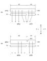
- FIG. 10A schematically shows the air flow when the separation portion 223 is not provided temporarily in a bottom view.
- an air flow that passes through the range A1 and flows along the flap 71 is indicated by an arrow AR51.
- a first flow such an air flow is referred to as a “first flow”.
- the first flow can be said to be one in which the flow direction is adjusted by the flap 71 among the flow of air blown from the opening 210.
- an air flow that passes through the above-described range A2 and flows along the flap 72 is indicated by an arrow AR52.
- a second flow such an air flow is referred to as a “second flow”.
- the second flow can be said to be one in which the flow direction is adjusted by the flap 72 among the flow of air blown from the opening 210.
- FIG. 10A shows a state in which the first flow and the second flow are attracted to each other in the left-right direction of the vehicle 800, but they are also attracted to each other in the vertical direction. .
- the occupant adjusts the inclination angles of the flap 71 and the flap 72 so that the first flow reaches the second row of seats 830 and the second flow reaches the third row of seats 830.
- air may not reach an appropriate position in either the seat 830 or the seat 840, which may cause an uncomfortable feeling to the occupant. is there.
- FIG. 10 (B) schematically shows the air flow in the present embodiment in a bottom view. Also in the figure, the first flow passing through the range A1 is indicated by an arrow AR51, and the second flow passing through the range A2 is indicated by an arrow AR52.
- the first flow and the second flow are separated by the separation unit 223.
- the phenomenon in which the first flow and the second flow are attracted to each other is prevented, so that the respective flows can be individually adjusted so that air can reach an appropriate position in either the seat 830 or the seat 840. It is possible.
- the flap 71 that adjusts the flow direction of the air blown out as the first flow at a position downstream of the opening 210 in the arm portion 200, and the flow direction of the air blown out as the second flow
- a flap 72 for adjusting the angle corresponds to the “first flap” in the present embodiment.
- the flap 72 corresponds to the “second flap” in the present embodiment.
- the fixing plate (plate which does not rotate) which prescribes
- regulates the flow direction of a 2nd flow are attached to the arm part 200.
- An aspect may be sufficient. Also in such an aspect, the separation part 223 has the same effect as described above.
- the separation part 223 may be formed to extend from the upper surface 523a of the guide part 523 toward the lower surface 220a of the guide plate 220.
- the upper surface 523a of the guide portion 523 corresponds to the first wall surface
- the lower surface 220a of the guide plate 220 corresponds to the second wall surface.
- the dimension (width W2) of the separation part 223 along the separation direction is as already described. 8 mm. According to experiments conducted by the present inventors, it has been found that if the first flow and the second flow are separated by 8 mm or more, a phenomenon in which the respective flows attract each other can be reliably prevented. For this reason, the dimension of the separation part 223 along the separation direction is desirably 8 mm or more.
- the shape of the separation portion 223 is formed such that the dimension along the left-right direction (that is, the separation direction) decreases toward the upstream side in the air flow direction.
- a shape of the separation part 223 may be different from that shown in FIG.
- the shape of the upstream portion (front side portion) in the air flow direction of the separation portion 223 may be a shape that protrudes in a circular arc shape when viewed from above.
- the upstream wall 223a may not be provided, and the inclined wall 223c and the inclined wall 223d may be directly connected. That is, the shape where the front-end
- a front side portion of the air guide portion 221 is arranged at a position overlapping the protruding portion 222 in the bottom view in the upper surface 220b opposite to the lower surface 220a of the guide plate 220. For this reason, the air flow that directly reaches the position of the protruding portion 222 is hindered by the air guide portion 221. In other words, it can be said that the air guide portion 221 disposed on the back surface side of the protruding portion 222 is provided at a position where the air flow that directly hits the protruding portion 222 is prevented.
- the front side portion of the air guide portion 221 is also arranged at a position on the upper surface 220b opposite to the lower surface 220a of the guide plate 220 so as to overlap with the separation portion 223 in the bottom view. For this reason, the air flow that directly reaches the position of the separation part 223 is hindered by the air guide part 221. In other words, it can be said that the air guide portion 221 disposed on the back surface side of the separation portion 223 is provided at a position where the flow of air impinges directly on the separation portion 223 is obstructed.
- FIG. 11 the interior of the passenger compartment is shown in a top view.
- the flow of air sucked from the opening 110 of the main body 100 is indicated by an arrow AR21.
- the flow of air blown rearward from the opening 210 is indicated by arrows AR31 and AR32.
- arrow AR31 is the flow of the air blown out along the flap 71 (refer FIG. 3) arrange
- an arrow AR32 is a flow of air blown out along the flap 72 (see FIG. 3) arranged on the inner side, that is, a second flow.
- the width of the third row of seats 840 arranged on the rear side of the vehicle 800 is the same as the width of the second row of seats 830 in order to avoid interference with the rear wheels (not shown). It is narrower than that. For this reason, it is desirable to adjust the angle of the flap 72 so that the air blown along the inner flap 72 reaches the seat 840. Considering this point and the point that air does not easily reach the rear side of the vehicle 800, the dimension of the flap 72 in the longitudinal direction is longer than the dimension of the flap 71 in the longitudinal direction.
- the first flow guided by the flap 71 and the second flow guided by the flap 72 are separated from each other by the separation unit 223.
- the occurrence of a phenomenon in which the two flows are attracted to each other is prevented, so that the air blown out from the opening 210 can surely reach the appropriate positions of the seat 830 and the seat 840, respectively. ing.
- the air existing in the vicinity of the in-vehicle circulator 10 in the passenger compartment includes, for example, a low-temperature conditioned air blown from the vehicle air conditioner and a higher-temperature air.
- the opening 110 which is the inlet of the air to be sucked, is formed so as to extend over substantially the entire left and right direction, not only low-temperature conditioned air but also high-temperature air is sucked from the opening 110. Will end up.
- the air after these are mixed is blown out from the opening 210, the temperature becomes higher than the temperature of the conditioned air. Since air having a temperature different from that of the conditioned air reaches the seat 830 and the seat 840 as described above, the comfort on the rear side is impaired.
- an opening 110 is formed only in a relatively narrow range in the left-right direction of the vehicle 800, specifically, only in the main body 100 sandwiched between the pair of arms 200. Yes. Further, the opening 110 is formed at a center position in the left-right direction of the vehicle 800. Such a position is a position in the passenger compartment that can easily reach the conditioned air blown from the vehicle air conditioner at the temperature at which it was blown.
- the air-conditioning air outlet (opening 811) formed on the center side of the front panel 810 is often larger than the air-conditioning air outlet (opening 812) formed on the left and right ends of the front panel. It depends.
- the flow of the conditioned air blown from the central opening 811 is indicated by an arrow AR11
- the flow of the conditioned air blown from the openings 812 at both left and right ends is indicated by an arrow AR12. Since a large amount of conditioned air blown from the opening 811 reaches the vicinity of the main body 100 where the opening 110 is formed, air having a comfortable temperature is easily sucked from the opening 110. Since the air is blown out to the rear side of the vehicle 800 (without being mixed with hot air), the rear side where the seat 830 and the seat 840 are provided can be kept comfortable.
- an opening 813 that is a blowout port for air-conditioning air is formed at the center of the upper surface of the front panel 810 at the center of the left and right.
- the conditioned air blown from the opening 813 flows upward along the windshield 801 and then reaches the opening 110.
- the opening 813 is formed as a dedicated opening for allowing the main stream of the conditioned air to reach the opening 110 of the in-vehicle circulator 10.
Landscapes
- Physics & Mathematics (AREA)
- Thermal Sciences (AREA)
- Engineering & Computer Science (AREA)
- Mechanical Engineering (AREA)
- Air-Conditioning For Vehicles (AREA)
Applications Claiming Priority (2)
| Application Number | Priority Date | Filing Date | Title |
|---|---|---|---|
| JP2016106920A JP6569599B2 (ja) | 2016-05-30 | 2016-05-30 | 車載用サーキュレータ |
| JP2016-106920 | 2016-05-30 |
Publications (1)
| Publication Number | Publication Date |
|---|---|
| WO2017208611A1 true WO2017208611A1 (ja) | 2017-12-07 |
Family
ID=60479300
Family Applications (1)
| Application Number | Title | Priority Date | Filing Date |
|---|---|---|---|
| PCT/JP2017/013919 Ceased WO2017208611A1 (ja) | 2016-05-30 | 2017-04-03 | 車載用サーキュレータ |
Country Status (2)
| Country | Link |
|---|---|
| JP (1) | JP6569599B2 (https=) |
| WO (1) | WO2017208611A1 (https=) |
Citations (5)
| Publication number | Priority date | Publication date | Assignee | Title |
|---|---|---|---|---|
| JPH09207550A (ja) * | 1996-01-31 | 1997-08-12 | Mitsubishi Heavy Ind Ltd | 車両用後席天井設置型空気調和機 |
| JP2004276852A (ja) * | 2003-03-18 | 2004-10-07 | Honda Motor Co Ltd | 車両用空調ダクト構造 |
| WO2016051753A1 (ja) * | 2014-10-02 | 2016-04-07 | 株式会社デンソー | 送風装置 |
| WO2016059778A1 (ja) * | 2014-10-17 | 2016-04-21 | 株式会社デンソー | 送風装置 |
| JP2016074310A (ja) * | 2014-10-07 | 2016-05-12 | 株式会社デンソー | 車両空調装置 |
-
2016
- 2016-05-30 JP JP2016106920A patent/JP6569599B2/ja active Active
-
2017
- 2017-04-03 WO PCT/JP2017/013919 patent/WO2017208611A1/ja not_active Ceased
Patent Citations (5)
| Publication number | Priority date | Publication date | Assignee | Title |
|---|---|---|---|---|
| JPH09207550A (ja) * | 1996-01-31 | 1997-08-12 | Mitsubishi Heavy Ind Ltd | 車両用後席天井設置型空気調和機 |
| JP2004276852A (ja) * | 2003-03-18 | 2004-10-07 | Honda Motor Co Ltd | 車両用空調ダクト構造 |
| WO2016051753A1 (ja) * | 2014-10-02 | 2016-04-07 | 株式会社デンソー | 送風装置 |
| JP2016074310A (ja) * | 2014-10-07 | 2016-05-12 | 株式会社デンソー | 車両空調装置 |
| WO2016059778A1 (ja) * | 2014-10-17 | 2016-04-21 | 株式会社デンソー | 送風装置 |
Also Published As
| Publication number | Publication date |
|---|---|
| JP6569599B2 (ja) | 2019-09-04 |
| JP2017213920A (ja) | 2017-12-07 |
Similar Documents
| Publication | Publication Date | Title |
|---|---|---|
| CN105564193B (zh) | 车辆的除霜构造 | |
| JP6365759B2 (ja) | 空気吹出装置 | |
| CN105774475B (zh) | 出风口 | |
| JP2014019270A (ja) | 車両用空調装置 | |
| JP5827099B2 (ja) | レジスタ | |
| JP2015020566A (ja) | 車両用空調装置の吹出口構造 | |
| JP6428004B2 (ja) | 送風装置 | |
| CN104417321B (zh) | 通风管道连接结构 | |
| CN104884328B (zh) | 车辆空调系统及具有该车辆空调系统的铁道车辆 | |
| JP6883452B2 (ja) | 車両用空気吹出装置 | |
| JP6627976B2 (ja) | 車両用空調装置 | |
| JP6358028B2 (ja) | 車両空調装置 | |
| US11511602B2 (en) | Wind direction adjusting apparatus | |
| JP6601315B2 (ja) | 車載用サーキュレータ | |
| JP6569599B2 (ja) | 車載用サーキュレータ | |
| JP6544165B2 (ja) | 送風装置 | |
| JP6547684B2 (ja) | 車載用サーキュレータ | |
| JP2017213921A (ja) | 車載用サーキュレータ | |
| EP3981621A1 (en) | Vehicular air-conditioning device | |
| WO2016051754A1 (ja) | 送風装置 | |
| CN112874482A (zh) | 除霜器结构 | |
| JP6642011B2 (ja) | 送風装置 | |
| JP6415189B2 (ja) | 風向制御構造 | |
| JP7068799B2 (ja) | 車両用送風装置 | |
| JP6064503B2 (ja) | 車両用空調ユニット |
Legal Events
| Date | Code | Title | Description |
|---|---|---|---|
| 121 | Ep: the epo has been informed by wipo that ep was designated in this application |
Ref document number: 17806172 Country of ref document: EP Kind code of ref document: A1 |
|
| NENP | Non-entry into the national phase |
Ref country code: DE |
|
| 122 | Ep: pct application non-entry in european phase |
Ref document number: 17806172 Country of ref document: EP Kind code of ref document: A1 |