WO2017208548A1 - 内燃機関のバルブタイミング制御装置 - Google Patents
内燃機関のバルブタイミング制御装置 Download PDFInfo
- Publication number
- WO2017208548A1 WO2017208548A1 PCT/JP2017/008073 JP2017008073W WO2017208548A1 WO 2017208548 A1 WO2017208548 A1 WO 2017208548A1 JP 2017008073 W JP2017008073 W JP 2017008073W WO 2017208548 A1 WO2017208548 A1 WO 2017208548A1
- Authority
- WO
- WIPO (PCT)
- Prior art keywords
- contact surface
- timing control
- valve timing
- combustion engine
- internal combustion
- Prior art date
- Legal status (The legal status is an assumption and is not a legal conclusion. Google has not performed a legal analysis and makes no representation as to the accuracy of the status listed.)
- Ceased
Links
Images


Classifications
-
- F—MECHANICAL ENGINEERING; LIGHTING; HEATING; WEAPONS; BLASTING
- F01—MACHINES OR ENGINES IN GENERAL; ENGINE PLANTS IN GENERAL; STEAM ENGINES
- F01L—CYCLICALLY OPERATING VALVES FOR MACHINES OR ENGINES
- F01L1/00—Valve-gear or valve arrangements, e.g. lift-valve gear
- F01L1/34—Valve-gear or valve arrangements, e.g. lift-valve gear characterised by the provision of means for changing the timing of the valves without changing the duration of opening and without affecting the magnitude of the valve lift
- F01L1/344—Valve-gear or valve arrangements, e.g. lift-valve gear characterised by the provision of means for changing the timing of the valves without changing the duration of opening and without affecting the magnitude of the valve lift changing the angular relationship between crankshaft and camshaft, e.g. using helicoidal gear
- F01L1/356—Valve-gear or valve arrangements, e.g. lift-valve gear characterised by the provision of means for changing the timing of the valves without changing the duration of opening and without affecting the magnitude of the valve lift changing the angular relationship between crankshaft and camshaft, e.g. using helicoidal gear making the angular relationship oscillate, e.g. non-homokinetic drive
-
- F—MECHANICAL ENGINEERING; LIGHTING; HEATING; WEAPONS; BLASTING
- F01—MACHINES OR ENGINES IN GENERAL; ENGINE PLANTS IN GENERAL; STEAM ENGINES
- F01L—CYCLICALLY OPERATING VALVES FOR MACHINES OR ENGINES
- F01L1/00—Valve-gear or valve arrangements, e.g. lift-valve gear
- F01L1/34—Valve-gear or valve arrangements, e.g. lift-valve gear characterised by the provision of means for changing the timing of the valves without changing the duration of opening and without affecting the magnitude of the valve lift
- F01L1/344—Valve-gear or valve arrangements, e.g. lift-valve gear characterised by the provision of means for changing the timing of the valves without changing the duration of opening and without affecting the magnitude of the valve lift changing the angular relationship between crankshaft and camshaft, e.g. using helicoidal gear
- F01L1/3442—Valve-gear or valve arrangements, e.g. lift-valve gear characterised by the provision of means for changing the timing of the valves without changing the duration of opening and without affecting the magnitude of the valve lift changing the angular relationship between crankshaft and camshaft, e.g. using helicoidal gear using hydraulic chambers with variable volume to transmit the rotating force
-
- B—PERFORMING OPERATIONS; TRANSPORTING
- B21—MECHANICAL METAL-WORKING WITHOUT ESSENTIALLY REMOVING MATERIAL; PUNCHING METAL
- B21K—MAKING FORGED OR PRESSED METAL PRODUCTS, e.g. HORSE-SHOES, RIVETS, BOLTS OR WHEELS
- B21K1/00—Making machine elements
- B21K1/20—Making machine elements valve parts
- B21K1/22—Making machine elements valve parts poppet valves, e.g. for internal-combustion engines
-
- F—MECHANICAL ENGINEERING; LIGHTING; HEATING; WEAPONS; BLASTING
- F01—MACHINES OR ENGINES IN GENERAL; ENGINE PLANTS IN GENERAL; STEAM ENGINES
- F01L—CYCLICALLY OPERATING VALVES FOR MACHINES OR ENGINES
- F01L1/00—Valve-gear or valve arrangements, e.g. lift-valve gear
- F01L1/34—Valve-gear or valve arrangements, e.g. lift-valve gear characterised by the provision of means for changing the timing of the valves without changing the duration of opening and without affecting the magnitude of the valve lift
- F01L1/344—Valve-gear or valve arrangements, e.g. lift-valve gear characterised by the provision of means for changing the timing of the valves without changing the duration of opening and without affecting the magnitude of the valve lift changing the angular relationship between crankshaft and camshaft, e.g. using helicoidal gear
- F01L1/3442—Valve-gear or valve arrangements, e.g. lift-valve gear characterised by the provision of means for changing the timing of the valves without changing the duration of opening and without affecting the magnitude of the valve lift changing the angular relationship between crankshaft and camshaft, e.g. using helicoidal gear using hydraulic chambers with variable volume to transmit the rotating force
- F01L2001/3445—Details relating to the hydraulic means for changing the angular relationship
- F01L2001/34453—Locking means between driving and driven members
- F01L2001/34456—Locking in only one position
-
- F—MECHANICAL ENGINEERING; LIGHTING; HEATING; WEAPONS; BLASTING
- F01—MACHINES OR ENGINES IN GENERAL; ENGINE PLANTS IN GENERAL; STEAM ENGINES
- F01L—CYCLICALLY OPERATING VALVES FOR MACHINES OR ENGINES
- F01L1/00—Valve-gear or valve arrangements, e.g. lift-valve gear
- F01L1/34—Valve-gear or valve arrangements, e.g. lift-valve gear characterised by the provision of means for changing the timing of the valves without changing the duration of opening and without affecting the magnitude of the valve lift
- F01L1/344—Valve-gear or valve arrangements, e.g. lift-valve gear characterised by the provision of means for changing the timing of the valves without changing the duration of opening and without affecting the magnitude of the valve lift changing the angular relationship between crankshaft and camshaft, e.g. using helicoidal gear
- F01L1/3442—Valve-gear or valve arrangements, e.g. lift-valve gear characterised by the provision of means for changing the timing of the valves without changing the duration of opening and without affecting the magnitude of the valve lift changing the angular relationship between crankshaft and camshaft, e.g. using helicoidal gear using hydraulic chambers with variable volume to transmit the rotating force
- F01L2001/3445—Details relating to the hydraulic means for changing the angular relationship
- F01L2001/34453—Locking means between driving and driven members
- F01L2001/34469—Lock movement parallel to camshaft axis
-
- F—MECHANICAL ENGINEERING; LIGHTING; HEATING; WEAPONS; BLASTING
- F01—MACHINES OR ENGINES IN GENERAL; ENGINE PLANTS IN GENERAL; STEAM ENGINES
- F01L—CYCLICALLY OPERATING VALVES FOR MACHINES OR ENGINES
- F01L1/00—Valve-gear or valve arrangements, e.g. lift-valve gear
- F01L1/34—Valve-gear or valve arrangements, e.g. lift-valve gear characterised by the provision of means for changing the timing of the valves without changing the duration of opening and without affecting the magnitude of the valve lift
- F01L1/344—Valve-gear or valve arrangements, e.g. lift-valve gear characterised by the provision of means for changing the timing of the valves without changing the duration of opening and without affecting the magnitude of the valve lift changing the angular relationship between crankshaft and camshaft, e.g. using helicoidal gear
- F01L1/3442—Valve-gear or valve arrangements, e.g. lift-valve gear characterised by the provision of means for changing the timing of the valves without changing the duration of opening and without affecting the magnitude of the valve lift changing the angular relationship between crankshaft and camshaft, e.g. using helicoidal gear using hydraulic chambers with variable volume to transmit the rotating force
- F01L2001/3445—Details relating to the hydraulic means for changing the angular relationship
- F01L2001/34479—Sealing of phaser devices
-
- F—MECHANICAL ENGINEERING; LIGHTING; HEATING; WEAPONS; BLASTING
- F01—MACHINES OR ENGINES IN GENERAL; ENGINE PLANTS IN GENERAL; STEAM ENGINES
- F01L—CYCLICALLY OPERATING VALVES FOR MACHINES OR ENGINES
- F01L1/00—Valve-gear or valve arrangements, e.g. lift-valve gear
- F01L1/34—Valve-gear or valve arrangements, e.g. lift-valve gear characterised by the provision of means for changing the timing of the valves without changing the duration of opening and without affecting the magnitude of the valve lift
- F01L1/344—Valve-gear or valve arrangements, e.g. lift-valve gear characterised by the provision of means for changing the timing of the valves without changing the duration of opening and without affecting the magnitude of the valve lift changing the angular relationship between crankshaft and camshaft, e.g. using helicoidal gear
- F01L1/3442—Valve-gear or valve arrangements, e.g. lift-valve gear characterised by the provision of means for changing the timing of the valves without changing the duration of opening and without affecting the magnitude of the valve lift changing the angular relationship between crankshaft and camshaft, e.g. using helicoidal gear using hydraulic chambers with variable volume to transmit the rotating force
- F01L2001/3445—Details relating to the hydraulic means for changing the angular relationship
- F01L2001/34483—Phaser return springs
-
- F—MECHANICAL ENGINEERING; LIGHTING; HEATING; WEAPONS; BLASTING
- F01—MACHINES OR ENGINES IN GENERAL; ENGINE PLANTS IN GENERAL; STEAM ENGINES
- F01L—CYCLICALLY OPERATING VALVES FOR MACHINES OR ENGINES
- F01L2250/00—Camshaft drives characterised by their transmission means
- F01L2250/02—Camshaft drives characterised by their transmission means the camshaft being driven by chains
-
- F—MECHANICAL ENGINEERING; LIGHTING; HEATING; WEAPONS; BLASTING
- F01—MACHINES OR ENGINES IN GENERAL; ENGINE PLANTS IN GENERAL; STEAM ENGINES
- F01L—CYCLICALLY OPERATING VALVES FOR MACHINES OR ENGINES
- F01L2303/00—Manufacturing of components used in valve arrangements
-
- F—MECHANICAL ENGINEERING; LIGHTING; HEATING; WEAPONS; BLASTING
- F02—COMBUSTION ENGINES; HOT-GAS OR COMBUSTION-PRODUCT ENGINE PLANTS
- F02D—CONTROLLING COMBUSTION ENGINES
- F02D13/00—Controlling the engine output power by varying inlet or exhaust valve operating characteristics, e.g. timing
- F02D13/02—Controlling the engine output power by varying inlet or exhaust valve operating characteristics, e.g. timing during engine operation
- F02D13/0203—Variable control of intake and exhaust valves
- F02D13/0215—Variable control of intake and exhaust valves changing the valve timing only
- F02D13/0219—Variable control of intake and exhaust valves changing the valve timing only by shifting the phase, i.e. the opening periods of the valves are constant
Definitions
- the present invention relates to a valve timing control device for an internal combustion engine that controls the opening / closing timing of an intake valve or an exhaust valve of the internal combustion engine in accordance with an operating state.
- this valve timing control device is provided integrally with a disc-shaped sprocket that rotates synchronously with the crankshaft via a timing chain, and a bottomed cylindrical housing with a plurality of shoes protruding on the inner peripheral side, A vane rotor that is fastened to one end portion of the camshaft through a boss portion that is inserted and fitted into the sprocket, and a plurality of vanes project from the outer peripheral side, and the vane rotor is relatively disposed on the inner peripheral side of the housing. It is configured by being housed and arranged to be rotatable.
- the present invention has been devised in view of the actual situation of the conventional valve timing control device, and provides a valve timing control device for an internal combustion engine that can suppress deformation of a specific shoe. It is aimed.
- the present invention is a pair of specific shoes that are substantially parallel to the contact surface at circumferential positions that do not overlap with the contact surface with which the specific vane contacts in the radial direction of the housing body.
- a recess having a side surface is provided.
- the present invention is a specific shoe, and a recess is provided on the opposite side of the contact surface in the circumferential direction with respect to the bolt insertion hole.
- the deformation of a specific shoe can be suppressed.
- FIG. 1 is an exploded perspective view of a valve timing control device for an internal combustion engine according to a first embodiment of the present invention.
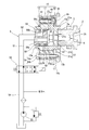
- FIG. 2 is a longitudinal sectional view of a valve timing control device for an internal combustion engine shown in FIG. 1 and a main diagram showing a hydraulic circuit according to the longitudinal cross-sectional view.
- FIG. 2 is a front view of the valve timing control device shown in FIG. 1 with a front plate removed, showing a non-locked state of the vane rotor.
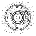
- FIG. 2 is a front view of the valve timing control device shown in FIG. 1 with a front plate removed, showing a locked state of the vane rotor.
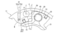
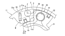
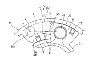
- FIG. 5 is an enlarged view of a main part of FIG. 4, in which a sprocket is omitted from FIG. 4.
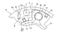
- FIG. 6 is a view corresponding to FIG. 5 illustrating a first modification of the first embodiment of the present invention.
- FIG. 6 is a view corresponding to FIG. 5 illustrating a second modification of the first embodiment of the present invention.
- FIG. 6 is a view corresponding to FIG. 5 illustrating a second embodiment of the present invention.
- valve timing control device for an internal combustion engine according to the present invention
- the apparatus is applied to an intake side valve operating apparatus, as in the prior art.
- the left side of FIG. 2 will be described as “front” and the right side will be described as “rear”.
- FIGS. 1 to 5 show a first embodiment of a valve timing control device for an internal combustion engine according to the present invention.
- This valve timing control device as shown in FIGS. are interposed between a sprocket 13 that is rotationally driven with the camshaft 2 provided so as to be relatively rotatable with respect to the sprocket 13, and the operation is controlled through a predetermined hydraulic supply / discharge means 5. The relative rotational phase of 1 and 2 is converted.
- the housing 10 is provided integrally with the sprocket 13 and has four first to fourth shoes S1 to S4 projecting on the inner peripheral side, and is relatively rotatable on the inner peripheral side of the housing 10.
- a vane rotor 20 that is provided with four vanes (first to fourth vanes V1 to V4) projectingly on the outer peripheral side.
- the vanes V1 to V4 provide a pair of retarded working chambers (hereinafter abbreviated as “retarded chambers”) Re and advanced working chambers (hereinafter referred to as “retarded working chambers”).
- the abbreviation chamber is abbreviated as “advance angle chamber.”)
- the operation is controlled by selectively supplying hydraulic pressure to the operation chambers Ad and Re from the hydraulic supply / exhaust means 5 separately.
- the camshaft 2 is rotatably supported via a bearing 3 provided on a cylinder head (not shown), and an engine valve (not shown) via a drive cam (not shown) provided at a predetermined position on the outer periphery. Open the intake valve.
- the front end portion of the camshaft 2 is provided with a rotor connection portion 2a that faces the inner peripheral side of a rear end portion of a cylindrical portion 17 to be described later and serves for connection with the vane rotor 20, and the rotor connection portion 2a
- An internal thread portion 2b to which a cam bolt 4 for fastening the vane rotor 20 is screwed is formed in the internal axial direction.
- the housing 10 includes a cylindrical housing body 11 having openings at both axial ends, a front plate 12 that closes a front end opening of the housing body 11, and a rear that closes a rear end opening of the housing body 11.
- the sprocket 13 constituting the plate is fixed together by a plurality of (four in this embodiment) bolts 14.
- the housing body 11 is integrally formed of a sintered metal material, and the first to fourth shoes S1 to S4 are integrally projected inward at substantially equal intervals in the circumferential direction on the inner peripheral side. ing.
- Each of the first to fourth shoes S1 to S4 has a substantially rectangular shape in plan view, and the bolts 14 are inserted in the direction of the internal axis on the base end side to be fastened to the sprocket 13 together.
- Bolt insertion holes 11a are formed so as to penetrate, and substantially prismatic seal members 15 are fitted into seal grooves that are recessed in the axial direction on the respective tip sides.
- a positioning pin (described later) projecting from the sprocket 13 is provided on the outer peripheral side of the first shoe S1, which is a specific shoe with which a first vane V1 (described later) abuts.
- Engagement grooves 31 serving as recesses (grooves) for positioning in the rotational direction of the housing body 11 and the sprocket 13 by engaging with the housing 19 are formed.
- the engagement groove 31 is notched in a substantially straight shape with respect to the housing body 11 from the radially outer side to the radially inner side, and the vane rotor 20 described later is locked when the vane rotor 20 is locked.
- the housing body 11 and the sprocket 13 are positioned in the rotational direction via the positioning pin 19 with a two-surface width W consisting of a pair of side surfaces 31a and 31a that are substantially parallel to the contact surface 30 that contacts the first vane V1.
- the engagement groove 31 is located on the opposite side of the contact surface 30 with respect to the bolt insertion hole 11a in the first shoe S1, and is relatively thick in the circumferential direction. It is provided in the part S1a.
- the above “substantially parallel” is preferably within a range of ⁇ 3 °.
- the first shoe S1 is configured such that the bolt insertion hole 11a is positioned on the extension of the perpendicular P to the contact surface 30 and the bolt insertion hole on the extension of the perpendicular P to the contact surface 30.
- the shaft center Z of the bolt 14 inserted into the housing 11a is positioned so that the contact surface 30 and the bolt 14 overlap in the circumferential direction of the housing body 11 when viewed from the axial direction of the housing body 11.
- the contact surface 30 is positioned on a virtual circle C formed by the radial width of the shaft portion 14b of the bolt 14.
- the seat surface of the head portion 14a of the bolt 14 and the seal member 15 are arranged in the circumferential direction of the housing body 11 when viewed from the axial direction of the housing body 11. It is configured to overlap.
- the front plate 12 has a disk shape made of a predetermined metal material, and a rotor insertion hole 12 a through which a front end portion of a rotor main body 21 to be described later passes is inserted at a substantially central position.
- four bolt insertion holes 12b are formed penetratingly formed at positions corresponding to the respective bolt insertion holes 11a on the outer peripheral side so that the bolts 14 are inserted into the sprocket 13 and fixed together. Yes.
- the sprocket 13 as the rear plate is integrally formed of sintered metal, is provided in a flat shape at the front end portion, and is provided with an end wall 16 that is used to fasten the housing body 11 and the front plate 12 together.
- a hollow cylindrical portion 17 extending in the axial direction from the rear end surface of the sprocket 13 and a radially projecting projection on the outer peripheral side of the cylindrical portion 17 are wound around and meshed with a timing chain (not shown). And a plurality of tooth portions 18 used for transmitting the rotational force of the crankshaft.
- the end wall 16 is formed with a rotor insertion hole 13a through which a rear end portion of a rotor body 21 described later is inserted at a substantially central position, and a position corresponding to each of the bolt insertion holes 11a on the outer peripheral side.
- a female screw hole 13 b is provided for use in fastening together with the housing body 11 and the front plate 12 by screwing the male screw portion 14 c of each bolt 14.
- the formation margin of the internal thread hole 13b is ensured by protrudingly projecting the inner peripheral side of each said tooth part 18 partially.
- the phase alignment of the sprocket 13 and the crankshaft via the timing chain is performed.
- a predetermined alignment mark 13c for use in the above is formed, and a protrusion for performing phase alignment between the sprocket 13 and the housing body 11 by engaging and engaging with the engagement groove 31 on the inner peripheral side of the alignment mark 13c.
- a pin holding hole 13d for holding a positioning pin 19 as a portion is formed, and the positioning pin 19 is press-fitted and fixed in the pin holding hole 13d.
- the vane rotor 20 is integrally formed of a predetermined metal material, and is provided in a substantially cylindrical shape at the center, and is provided with a rotor main body 21 for connection with the camshaft 2 and the hydraulic supply / discharge means 5, and the rotor
- the first to fourth vanes V1 to V4 are provided mainly projecting radially from the outer peripheral side of the main body 21 and serving as compartments for the retard chambers Re and the advance chambers Ad.
- the rotor body 21 has a substantially bottomed cylindrical shape that opens forward, and supplies and discharges hydraulic pressure to and from the working chambers Ad and Re through the hydraulic supply and discharge means 5. It is mainly comprised from the cylindrical part 21a with which it uses, and the end wall 21b with which the rear end side of this cylindrical part 21a is obstruct
- the cylindrical portion 21a is configured such that the outer peripheral side can be slidably contacted with the seal member 15 fitted to the shoes S1 to S4, and holds the working chambers Ad and Re in an airtight manner. Further, on the inner peripheral side of the cylindrical portion 21a, a passage constituting member 56 described later is configured to be insertable, and in the inner radial direction on both sides in the circumferential direction with the vanes V1 to V4 interposed therebetween, The retard angle side oil hole 23 that can communicate with each retard angle chamber Re and the advance angle side oil hole 24 that can communicate with each advance angle chamber Ad are formed through the oil holes 23 and 24, respectively. The hydraulic pressure can be supplied to and discharged from the working chambers Ad and Re.
- a bolt insertion hole 21c used for fastening the vane rotor 20 by the cam bolt 4 is formed in the end wall 21b along the axial direction substantially at the center, and the head of the cam bolt 4 inserted through the bolt insertion hole 21c. The portion is seated on the front end surface of the end wall 21b, so that the vane rotor 20 can be fastened to the camshaft 2.
- Each of the vanes V1 to V4 is disposed between the shoes S1 to S4 as shown in FIGS. 1, 3, and 4, and is a seal recessed in the axial direction on each tip side.
- a substantially prismatic seal member 22 is fitted in the groove, and each seal member 22 is in sliding contact with the inner peripheral surface of the housing body 11, thereby forming a space formed between the shoes S1 to S4.
- the first vane V1 is configured as a specific widened vane having a larger circumferential width than the other vanes V2 to V4, and is adjacent to the vane rotor 20 at the maximum relative rotation. Further contact with the shoes S1 and S2 restricts further rotation of the vane rotor 20.
- the first vane V1 contains a known lock mechanism 40 that holds the phase of the vane rotor 20 while the first vane V1 is in contact with the contact surface 30 when the engine is stopped, which will be described later. ing.
- the lock mechanism 40 is slidably accommodated in a pin accommodating hole 43 formed so as to penetrate the first vane V1 in the inner axial direction, and engages with an engagement hole 44 formed in the sprocket 13 to engage the vane rotor. 20 and a substantially cylindrical lock pin 41 for restricting relative movement between the housing 10 and a spring 42 that is interposed between the lock pin 41 and the front plate 12 and biases the lock pin 41 toward the sprocket 13. , Mainly composed of.
- the hydraulic supply / discharge means 5 selectively supplies hydraulic pressure to the working chambers Ad and Re, or discharges hydraulic oil in the working chambers Ad and Re.
- the retard angle side oil passages 51 connected to the respective retard angle side oil holes 23, the advance angle side oil passages 52 connected to the respective advance angle side oil holes 24, and a known solenoid valve 55.
- An oil pump 53 that is a hydraulic pressure source that supplies hydraulic pressure to the oil passages 51 and 52 on one side, and a drain passage that is connected to the other oil passages 51 and 52 that are not connected to the oil pump 53 via the electromagnetic valve 55. 54.
- the retard angle side oil passage 51 and the advance angle side oil passage 52 communicate with the retard angle side oil hole 23 and the advance angle side oil hole 24 through a passage constituting member 56 connected to the tubular portion 21a of the vane rotor 20. It is configured to be possible. Specifically, the retard angle side oil passage 51 is formed between the retard angle side connection passage 56 a provided along the internal axial direction of the passage constituting member 56 and the axial direction between the vane rotor 20 and the passage constituting member 56. The retarding angle side oil holes 23 communicate with each other through the communicating chamber 57.
- the advance side oil passage 52 includes an advance side connection passage 56 b provided in parallel with the retard side connection passage 56 a along the internal axis direction of the passage component member 56, and a distal end portion of the passage component member 56.
- the advance angle side oil holes 24 communicate with each other through an annular groove 56c provided on the outer peripheral side.
- annular grooves are formed along the circumferential direction on the outer peripheral side of the passage component member 56, and an annular seal member 58 is fitted in the annular groove. 58 is in sliding contact with the inner peripheral surface of the cylindrical portion 21a, so that the space between the communication chamber 57 and the annular groove 56c is sealed.
- the electromagnetic valve 55 is a two-way switching valve, and the oil passages 51 and 52 are controlled by a control signal from an electronic control unit (ECU) (not shown) output based on detection results of various on-vehicle sensors.
- ECU electronice control unit
- the connection between the oil pump 53 and the drain passage 54 is selectively switched.
- valve timing control apparatus for an internal combustion engine according to the present invention
- the vane rotor 20 that is not in contact with the contact surface 30 as shown in FIG. 3 is delayed by so-called alternating torque transmitted through the camshaft 2.
- the first vane V ⁇ b> 1 comes into contact with the contact surface 30 of the first shoe S ⁇ b> 1 and the lock pin 41 engages with the engagement hole 44 as shown in FIG. 4. 20 and the housing 10 are rotated together at the most retarded phase.
- the housing main body 11 in the housing 10 is based on the phase of the locked state, that is, the phase of the state in which the first vane V1 is in contact with the contact surface 30. And the sprocket 13 are aligned in the rotational direction.
- the engaging groove for engaging the positioning pin 19 for the phase alignment is adjacent to the contact surface 30 on the base end side (outer peripheral side) of the first shoe S1.
- the contact area of the first shoe S1 with the first vane V1 is eroded (limited) as a result of the formation of the engagement groove.
- the contact surface 30 contacts the first vane V1. There was a possibility that the surface pressure would be excessive and the first shoe S1 would be deformed.
- the conventional engagement groove is formed on the proximal end side of the first shoe S1 along the radial direction of the housing body 11 which is not parallel to the contact surface 30, the housing body 11 ( As the vane rotor 20 is centered with respect to the housing 10), the vane rotor 20 moves along the engagement groove. As a result, the vane rotor 20 is separated from the abutment surface 30, and proper phase alignment is difficult.
- the first shoe S1 is substantially parallel to the contact surface 30 at a circumferential position where it does not overlap with the contact surface 30 with the first vane V1.
- the engagement groove 31 having a pair of side surfaces 31a and 31a is provided.
- the above-mentioned “circumferential position that does not overlap with the contact surface 30” is, in other words, a position where the contact surface 30 and the engagement groove 31 do not overlap in the radial direction of the housing body 11.
- the contact area of the contact surface 30 with the first vane V1 is eroded by the engagement groove 31. (Restricted) will not be restricted. That is, a sufficient contact area of the contact surface 30 with the first vane V1 can be ensured, and the contact surface pressure with the first vane V1 on the contact surface 30 can be reduced. The deformation of S1 can be suppressed.
- the pair of side surfaces 31 a and 31 a of the engagement groove 31 are configured in parallel with the contact surface 30, so that when the vane rotor 20 is centered with respect to the housing body 11, The vane rotor 20 can be moved in parallel along the contact surface 30 while maintaining the contact state with the contact surface 30. That is, when the vane rotor 20 is centered with respect to the housing body 11, there is no possibility that the vane rotor 20 is separated from the contact surface 30, and appropriate phase alignment between the housing body 11 and the sprocket 13 can be performed.
- the engagement groove 31 having the two-surface width W composed of the pair of side surfaces 31a and 31a parallel to the contact surface 30 is in contact.
- the contact surface pressure with the first vane V ⁇ b> 1 at the corresponding contact surface 30 can be reduced, deformation of the first shoe S ⁇ b> 1 can be suppressed, and the vane rotor 20 with respect to the housing 10 can be suppressed.
- the positional deviation in the circumferential direction can be suppressed, and the assembly accuracy of the apparatus is improved.
- the engagement groove formed by notching a groove shape from the radially outer side to the inner side on the outer peripheral side of the housing body 11.
- 31 was illustrated, the recessed part which concerns on this invention is not limited to this groove-shaped form.
- the concave portion according to the present invention may be in a form having a two-surface width W composed of a pair of side surfaces 31a and 31a parallel to the contact surface 30. 6 and through holes 32 and 33 penetrating in the axial direction as shown in FIG. Even with such a configuration, the above-described unique effects of the present invention can be achieved with a two-surface width W parallel to the contact surface 30.
- the engagement groove 31 is disposed on the opposite side in the circumferential direction from the contact surface 30 with respect to the bolt insertion hole 11a in the first shoe S1. For this reason, the contact surface 30 and the bolt insertion hole 11a (bolt 14) can be brought closer to each other, and the rigidity of the first shoe S1 can be improved. As a result, the first vane V1 is in contact. It is possible to suppress the occurrence of displacement of the first shoe S1.
- the respective seal members 15 that are in sliding contact with the vane rotor 20 are provided on the radially inner side of the housing body 11 in the respective shoes S1 to S4, and of these, the seal members provided on the first shoe S1. 15 is provided on the opposite side of the contact surface 30 in the circumferential direction with respect to the bolt insertion hole 11a.
- the contact surface 30 and the bolt insertion hole 11a can be brought closer to each other by disposing the seal member 15 in the first shoe S1 at a position farther from the contact surface 30.
- the seal member 15 provided on the first shoe S1 is configured to overlap the seating surface of the head portion 14a of the bolt 14 in the radial direction of the housing body 11.
- the contact surface 30 and the bolts 14 are configured to overlap in the radial direction of the housing body 11. With this configuration, the radial range of the contact surface 30 can be expanded, and the occurrence of displacement of the first shoe S1 at the time of contact of the first vane V1 can be suppressed.
- the bolt insertion hole 11a is positioned on the extension of the perpendicular P to the contact surface 30.
- the axial center of the bolt 14 is positioned on the extension of the perpendicular P to the contact surface 30.
- FIG. 8 shows a second embodiment of the valve timing control apparatus for an internal combustion engine according to the present invention, in which the arrangement of the engagement grooves 31 according to the first embodiment is changed. Since the basic configuration other than such changes is the same as that of the first embodiment, the same components as those of the first embodiment are denoted by the same reference numerals and description thereof is omitted.
- the engagement groove 31 has the contact surface 30 that is a contact surface with the first vane V1 and the bolt insertion hole 11a in the first shoe S1. Between the circumferential direction.
- the arrangement of the engagement grooves 31 is merely changed, and the specific configuration of the engagement grooves 31 itself is the same as that in the first embodiment.
- the engagement groove 31 includes the contact surface 30 and the bolt insertion hole. 11a, the engagement groove 31 for phase alignment between the housing body 11 and the sprocket 13 can be disposed closer to the contact surface 30. The positional accuracy of the contact surface 30 can be further improved.
- the present invention is not limited to the configuration of the above-described embodiment, and can be freely changed according to the specification, cost, etc. of the application target as long as the above-described effects of the present invention can be achieved.
- a configuration in which the housing main body 11 is formed in a bottomed cylindrical shape and has only one of the front plate 12 and the rear plate (sprocket) 13 can be applied.
- valve timing control device for an internal combustion engine based on the embodiment described above, for example, the following modes can be considered.
- the cam body is provided with a housing body that is formed in a cylindrical shape that is open at both ends in the axial direction, and a plurality of shoes projecting from the inner periphery.
- a vane rotor that is fixed and accommodated in the housing main body so as to be relatively rotatable, and has a plurality of vanes that divide each shoe into an advance working chamber and a retard working chamber, and closes both ends of the housing body.
- a pair of plate members, a plurality of bolts that fasten together the housing body and the pair of plate members through bolt insertion holes formed through the shoes, and another of the vanes.
- the recess is provided on the opposite side of the contact surface in the circumferential direction with respect to the bolt insertion hole in the specific shoe.
- the recess is a groove formed in the housing body by being cut out from the radially outer side to the inner side.
- the recess is formed by a through hole penetrating in the axial direction in the housing body.
- the plurality of shoes have a plurality of seal members that are in sliding contact with the vane rotor, respectively, on the radially inner side of the housing body.
- the seal member in the specific shoe is provided on the opposite side in the circumferential direction of the contact surface with respect to the bolt insertion hole.
- the seal member and the seat surface of the head of the bolt overlap in the radial direction of the housing body. Has been.
- the recess is provided in a circumferential direction between the contact surface and the bolt insertion hole in the specific shoe. Yes.
- the contact surface and the bolts are configured to overlap in the radial direction of the housing body.
- the bolt insertion hole is located on an extension of a perpendicular to the contact surface.
- the axis of the bolt is located on an extension line of a perpendicular to the contact surface.
- the specific vane is formed so as to be slidable in the through hole formed in the through hole.
- a lock member that is housed and a biasing member that biases the lock member toward one side in the axial direction, and one of the pair of plate members has a lock recess into which the lock member can be engaged.
- the lock member is inserted into the lock recess when the relative phase of the vane rotor with respect to the housing body is the most retarded angle or most advanced angle. Enroll.
- the contact surface contacts the specific vane in a state where the lock member is engaged with the lock recess.
- the valve timing control device for an internal combustion engine is, in one aspect thereof, a housing main body that is formed in a cylindrical shape that opens at least one end in the axial direction, and a plurality of shoes project from the inner peripheral side.
- a vane rotor fixed to the camshaft and accommodated in the housing body so as to be relatively rotatable, and having a plurality of vanes that divide each shoe into an advance working chamber and a retard working chamber, and the housing body A plate member that closes the opening, a plurality of bolts that fasten and fix the housing body and the plate member through bolt insertion holes formed through the shoes, and a specific vane among the vanes.
- the bolt includes a lock mechanism that restricts relative rotation of the vane rotor, and a contact surface with which the specific vane contacts in a state where the lock member is engaged with the lock recess.
- a concave portion provided on the opposite side of the contact surface in the circumferential direction with respect to the insertion hole, and a convex portion provided on the plate member and engaged with the concave portion.
- the recess has a pair of side surfaces that are substantially parallel to the contact surface.
- the plurality of shoes have a plurality of seal members that are in sliding contact with the vane rotor, respectively, on the radially inner side of the housing body.
- the seal member in the specific shoe is provided on the opposite side of the contact surface in the circumferential direction with respect to the bolt insertion hole.
- the contact surface and the bolts overlap in the radial direction of the housing body.
Landscapes
- Engineering & Computer Science (AREA)
- Mechanical Engineering (AREA)
- General Engineering & Computer Science (AREA)
- Valve Device For Special Equipments (AREA)
Abstract
第1~第4シュー(S1),(S2),(S3),(S4)のうち第1シュー(S1)における第1ベーン(V1)との当接面(30)と重合しない周方向位置に、該当接面(30)とほぼ平行な1対の側面(31a),(31a)を有する係合溝(31)を設け、該係合溝(31)にスプロケット(13)に突設した位置決めピン(19)を係合させることによって、ハウジング本体(11)とスプロケット(13)との回転方向の位相合わせを行うこととした。
Description
本発明は、内燃機関の吸気弁ないし排気弁の開閉時期を運転状態に応じて制御する内燃機関のバルブタイミング制御装置に関する。
従来のバルブタイミング制御装置としては、例えば以下の特許文献1に記載されたものが知られている。
すなわち、このバルブタイミング制御装置は、タイミングチェーンを介してクランクシャフトと同期回転する円盤状のスプロケットと一体的に設けられ、内周側に複数のシューが突設された有底円筒状のハウジングと、前記スプロケットに挿通嵌合するボス部を介してカムシャフトの一端部に締結され、外周側に複数のベーンが突設されたベーンロータと、を備え、前記ハウジングの内周側に前記ベーンロータが相対回転可能に収容配置されることにより構成される。
そして、いわゆるロック機構を構成する幅広の特定のベーンが当接する特定のシューの当該当接面側に隣接した位置に径方向内側へと開口形成された凹部に、スプロケットのハウジングとの対向面に突設された凸部が係合することにより、タイミングスプロケットとハウジングとの相対位相の位置決めが図られている。
しかしながら、前記従来のバルブタイミング制御装置にあっては、とりわけ、前記凹部が前記当接面に隣接して設けられているため、この当接面のうち前記凹部が形成された外周側の所定範囲が前記特定のベーンとの当接に供されず、前記特定のシューにおける前記特定のベーンとの当接面積が制限されてしまっていた。これにより、前記特定のベーンが前記当接面に当接した際の接触面圧が過大となってしまい、その結果、前記特定のシューの変形を招来してしまうおそれがあった。
本発明は、前記従来のバルブタイミング制御装置の実情に鑑みて案出されたものであって、特定のシューの変形を抑制することができる内燃機関のバルブタイミング制御装置を提供することを1つの目的としている。
本発明は、その一態様として、特定のシューであって、ハウジング本体の径方向において特定のベーンが当接する当接面と重ならない周方向位置に、前記当接面とほぼ平行となる1対の側面を有する凹部が設けられている。
また、本発明は、他の態様として、特定のシューであって、ボルト挿通孔に対し前記当接面の周方向反対側に、凹部が設けられている。
本発明によれば、特定のシューの変形を抑制することができる。
以下、本発明に係る内燃機関のバルブタイミング制御装置の一実施形態を図面に基づいて説明する。なお、下記の実施形態では、当該装置を、従来と同様、吸気側の動弁装置に適用したものを示している。また、説明の便宜上、図2の左側を「前」、右側を「後」として説明する。
〔第1実施形態〕
図1~図5は本発明に係る内燃機関のバルブタイミング制御装置の第1実施形態を示し、このバルブタイミング制御装置は、図1、図2に示すように、図示外のクランクシャフトの回転力をもって回転駆動されるスプロケット13と、該スプロケット13に対して相対回転可能に設けられるカムシャフト2と、の間に介装され、所定の油圧給排手段5を通じて作動制御されることで、当該両者1,2の相対回転位相を変換するものである。
図1~図5は本発明に係る内燃機関のバルブタイミング制御装置の第1実施形態を示し、このバルブタイミング制御装置は、図1、図2に示すように、図示外のクランクシャフトの回転力をもって回転駆動されるスプロケット13と、該スプロケット13に対して相対回転可能に設けられるカムシャフト2と、の間に介装され、所定の油圧給排手段5を通じて作動制御されることで、当該両者1,2の相対回転位相を変換するものである。
具体的には、前記スプロケット13と一体的に設けられ、内周側に4つの第1~第4シューS1~S4が突設されたハウジング10と、該ハウジング10の内周側に相対回転可能に収容配置され、外周側に4つのベーン(第1~第4ベーンV1~V4)が突設されたベーンロータ20と、から主として構成されている。そして、前記各ベーンV1~V4によって、前記各シューS1~S4の周方向間を、1対の遅角作動室(以下、「遅角室」と略称する。)Reと進角作動室(以下、「進角室」と略称する。)Adとに分けて、これら各作動室Ad,Reに前記油圧給排手段5から選択的に油圧が供給されることにより作動制御される。
前記カムシャフト2は、図示外のシリンダヘッドに設けられた軸受部3を介して回転可能に支持され、外周部の所定位置に設けられた図示外の駆動カムを介して図示外の機関弁(吸気弁)を開作動させる。そして、このカムシャフト2の前端部には、後述する筒状部17の後端部内周側へと臨んでベーンロータ20との接続に供するロータ接続部2aが設けられると共に、該ロータ接続部2aの内部軸方向に、前記ベーンロータ20の締結に供するカムボルト4が螺着する雌ねじ部2bが形成されている。
前記ハウジング10は、軸方向両端側が開口形成された円筒状のハウジング本体11と、該ハウジング本体11の前端側開口を閉塞するフロントプレート12と、前記ハウジング本体11の後端側開口を閉塞するリヤプレートを構成するスプロケット13とが、複数(本実施形態では4つ)のボルト14により共締め固定されている。
前記ハウジング本体11は、焼結金属材料によって一体に形成されたもので、内周側の周方向ほぼ等間隔位置に前記第1~第4シューS1~S4が内方へと一体に突設されている。この第1~第4シューS1~S4は、それぞれ平面視ほぼ矩形状を呈し、各基端部側の内部軸方向に、前記各ボルト14が挿通して前記スプロケット13への共締め固定に供するボルト挿通孔11aが貫通形成されると共に、各先端側に軸方向へ沿って凹設されたシール溝内に、ほぼ角柱状のシール部材15が嵌着されている。
また、前記第1~第4シューS1~S4のうち、後述する第1ベーンV1が当接する特定のシューである第1シューS1の外周側には、スプロケット13に突設された後述の位置決めピン19と係合することによってハウジング本体11とスプロケット13の回転方向の位置決めに供する凹部(溝部)としての係合溝31が開口形成されている。
すなわち、前記係合溝31は、特に図5に示すように、ハウジング本体11に対し径方向外側から径方向内側へ向けてほぼ直線状に切欠形成されていて、後述するベーンロータ20のロック時に前記第1ベーンV1と当接する当接面30とほぼ平行となる1対の側面31a,31aからなる二面幅Wをもって、前記位置決めピン19を介してハウジング本体11とスプロケット13の回転方向の位置決めがなされている。また、この係合溝31は、第1シューS1において、ボルト挿通孔11aに対して前記当接面30とは周方向反対側の位置であって、周方向に比較的厚肉となる厚肉部S1aに設けられている。ここで、上記の「ほぼ平行」としては、±3°の範囲が好ましい。
また、前記第1シューS1では、前記当接面30に対する垂線Pの延長上にボルト挿通孔11aが位置するように構成されると共に、当該当接面30に対する垂線Pの延長上にボルト挿通孔11aに挿通するボルト14の軸心Zが位置するように構成されていて、ハウジング本体11の軸方向から見て当接面30とボルト14とがハウジング本体11の周方向にオーバーラップするような構成、換言すればボルト14の軸部14bの径方向幅からなる仮想円C上に当接面30が位置する構成となっている。さらに、前記第1シューS1では、図3、図4に示すように、ハウジング本体11の軸方向から見てボルト14の頭部14aの座面とシール部材15とがハウジング本体11の周方向にオーバーラップするような構成となっている。
前記フロントプレート12は、図1、図2に示すように、所定の金属材料からなる円板状を呈し、ほぼ中央位置に、後述するロータ本体21の前端部が挿通するロータ挿通孔12aが貫通形成されると共に、外周側の前記各ボルト挿通孔11aに対応する位置に、前記各ボルト14が挿通することで前記スプロケット13への共締め固定に供する4つのボルト挿通孔12bが貫通形成されている。
前記リヤプレートとしてのスプロケット13は、燒結金属により一体に成形されてなるもので、前端部に平坦状に設けられ、前記ハウジング本体11及びフロントプレート12との共締め固定に供する端壁16と、該スプロケット13の後端面より軸方向に沿って延設された中空状の筒状部17と、該筒状部17の外周側に放射状に突設され、図示外のタイミングチェーンが巻き掛け噛合されることで前記クランクシャフトの回転力の伝達に供する複数の歯部18と、を備える。
そして、前記端壁16には、ほぼ中央位置に、後述するロータ本体21の後端部が挿通するロータ挿通孔13aが貫通形成されると共に、外周側の前記各ボルト挿通孔11aに対応する位置に、前記各ボルト14の雄ねじ部14cが螺着することで前記ハウジング本体11及びフロントプレート12との共締め固定に供する雌ねじ穴13bが形成されている。なお、この雌ねじ穴13bの形成部分については、前記各歯部18の内周側を部分的に肉盛り状に突設することによって、当該雌ねじ穴13bの形成代が確保されている。
また、前記端壁16の前端側外周縁には、所定の周方向位置に、図1、図3、図4に示すように、前記タイミングチェーンを介したスプロケット13と前記クランクシャフトとの位相合わせに供する所定の合いマーク13cが形成されると共に、該合いマーク13cの内周側に、前記係合溝31に係入し係合することによりスプロケット13とハウジング本体11との位相合わせを行う凸部としての位置決めピン19を保持するピン保持穴13dが穿設されていて、該ピン保持穴13dに、前記位置決めピン19が圧入固定されている。
前記ベーンロータ20は、所定の金属材料によって一体に形成されたもので、中央部にほぼ円筒状に設けられ、前記カムシャフト2及び油圧給排手段5との接続に供するロータ本体21と、該ロータ本体21の外周側にほぼ放射状に突設され、前記各遅角室Re及び各進角室Adの区画に供する第1~第4ベーンV1~V4と、から主として構成される。
前記ロータ本体21は、図1、図2に示すように、前方へ向かって開口するほぼ有底円筒状を呈し、前記油圧給排手段5を通じた前記各作動室Ad,Reに対する油圧の給排に供する筒状部21aと、該筒状部21aの後端側を閉塞するかたちで設けられ、前記カムボルト4によるベーンロータ20の締結に供する端壁21bと、から主として構成される。
前記筒状部21aは、外周側が前記各シューS1~S4に嵌着されるシール部材15と摺接可能に構成され、前記各作動室Ad,Reを気密に保持する。また、この筒状部21aの内周側には、後述する通路構成部材56が嵌挿可能に構成されると共に、前記各ベーンV1~V4を挟んだ周方向の両側の内部径方向に、前記各遅角室Reと連通可能な遅角側油孔23と、前記各進角室Adと連通可能な進角側油孔24とがそれぞれ貫通形成されていて、該各油孔23,24を通じて前記各作動室Ad,Reへの油圧の給排が可能となっている。
前記端壁21bには、ほぼ中央部に、前記カムボルト4によるベーンロータ20の締結に供するボルト挿通孔21cが軸方向に沿って貫通形成されていて、該ボルト挿通孔21cに挿通したカムボルト4の頭部が当該端壁21bの前端面に着座することによって、ベーンロータ20のカムシャフト2への締結が可能となっている。
前記各ベーンV1~V4は、図1、図3、図4に示すように、前記各シューS1~S4の間に配置されると共に、各先端側に軸方向へと沿って凹設されたシール溝内に、ほぼ角柱状のシール部材22が嵌着されていて、この各シール部材22がハウジング本体11の内周面に摺接することにより、前記各シューS1~S4の間に形成される空間が、前記各対の油圧室Ad,Reに気密に区画されている。
また、前記各ベーンV1~V4のうち第1ベーンV1のみが他のベーンV2~V4に比べて大きな周方向幅を有する拡幅状の特定のベーンとして構成され、ベーンロータ20の最大相対回転時に隣接する前記各シューS1,S2と当接することにより、当該ベーンロータ20のそれ以上の回転が規制されるようになっている。そして、この第1ベーンV1の内部には、後述する機関停止時に当該第1ベーンV1が前記当接面30に当接した状態のままベーンロータ20の位相を保持する周知のロック機構40が収容されている。
このロック機構40は、第1ベーンV1の内部軸方向に貫通形成されたピン収容孔43内に摺動可能に収容され、スプロケット13に穿設された係合穴44と係合することでベーンロータ20とハウジング10の相対移動を規制するほぼ円筒状のロックピン41と、該ロックピン41とフロントプレート12の間に介装され、前記ロックピン41をスプロケット13側へと付勢するスプリング42と、から主として構成される。
すなわち、前記ロックピン41と前記係合穴44の位置が合致すると、前記スプリング42の付勢力によってロックピン41の先端部が係合穴44に押し込まれて、ハウジング10とベーンロータ20との相対回転が規制(ロック)される。一方、前記第1ベーンV1の内側面(スプロケット13との対向端面)に、遅角室Reと係合穴44とを連通する連通溝45が切欠形成されていて、該連通溝45を介して係合穴44内におけるロックピン41の先端側に油圧が作用することで、該油圧によってロックピン41が押し退けられ、前記ロックが解除されることとなる。
前記油圧給排手段5は、図2に示すように、前記各作動室Ad,Reに対し油圧を選択的に供給する、あるいは前記各作動室Ad,Re内の作動油を排出するものであって、前記各遅角側油孔23に接続される遅角側油通路51と、前記各進角側油孔24に接続される進角側油通路52と、周知の電磁弁55を介して一方側の油通路51,52に油圧を供給する油圧源であるオイルポンプ53と、前記電磁弁55を介して前記オイルポンプ53に接続されない他方側の油通路51,52に接続されるドレン通路54と、から主として構成されている。
前記遅角側油通路51及び進角側油通路52は、ベーンロータ20の筒状部21aに接続される通路構成部材56を介して前記遅角側油孔23及び進角側油孔24と連通可能に構成されている。具体的には、前記遅角側油通路51は、通路構成部材56の内部軸方向に沿って設けられた遅角側接続通路56aと、ベーンロータ20と通路構成部材56との軸方向間に形成される連通室57と、を介して前記各遅角側油孔23と連通する。他方、前記進角側油通路52は、通路構成部材56の内部軸方向に沿って前記遅角側接続通路56aと平行に設けられた進角側接続通路56bと、通路構成部材56の先端部外周側に設けられた環状溝56cと、を介して前記各進角側油孔24とが連通する。
また、前記通路構成部材56の外周側には、複数の円環溝が周方向に沿って切欠形成されると共に、該円環溝に環状のシール部材58が嵌着されていて、該シール部材58が前記筒状部21aの内周面と摺接することによって、連通室57と環状溝56cとの間がシールされている。
前記電磁弁55は、2方向切換弁であって、車載の各種センサの検出結果に基づいて出力される図示外の電子コントロールユニット(ECU)からの制御信号により、前記各油通路51,52とオイルポンプ53及びドレン通路54との接続を選択的に切換制御する。
以下、本発明に係る内燃機関のバルブタイミング制御装置の特徴的な作用を、図3、図4に基づいて説明する。
前記バルブタイミング制御装置では、機関停止状態になると、図3に示すような前記当接面30とは非当接状態にあるベーンロータ20がカムシャフト2を介して伝達されるいわゆる交番トルクにより最遅角側へと回動し、図4に示すように、第1ベーンV1が第1シューS1の当接面30に当接すると共に、ロックピン41が係合穴44に係合することにより、ベーンロータ20とハウジング10とが前記最遅角位相で一体に回転するようになっている。
このため、前記バルブタイミング制御装置では、当該装置の組立に際して、前記ロック状態の位相、すなわち第1ベーンV1が前記当接面30に当接した状態の位相を基準に、ハウジング10におけるハウジング本体11とスプロケット13との回転方向の位相合わせを行う。
ここで、従来では、前述したように、前記位相合わせのために位置決めピン19を係合する係合溝が第1シューS1の基端側(外周側)に前記当接面30に隣接して設けられていたため、かかる係合溝の形成に伴い、第1シューS1における第1ベーンV1との当接面積が侵食(制限)される結果、前記当接面30における第1ベーンV1との接触面圧が過大となってしまい、第1シューS1の変形を招来してしまうおそれがあった。
また、前記従来の係合溝は、前記第1シューS1の基端側に、前記当接面30とは非平行となるハウジング本体11の径方向に沿って形成されていたため、ハウジング本体11(ハウジング10)に対するベーンロータ20の芯出しに伴いベーンロータ20が当該係合溝に沿って移動する結果、ベーンロータ20が前記当接面30から離間してしまい、適切な位相合わせが困難となっていた。
これに対して、本実施形態に係るバルブタイミング制御装置では、前記第1シューS1のうち第1ベーンV1との当接面30と重合しない周方向位置に、該当接面30とほぼ平行となる1対の側面31a,31aを有する前記係合溝31を設けることとした。なお、上記の「当接面30と重合しない周方向位置」とは、換言すれば、当接面30と係合溝31とがハウジング本体11の径方向において重ならない位置である。
このように、前記係合溝31を、前記当接面30と重合しない周方向位置に設けたことにより、当該係合溝31によって当接面30の第1ベーンV1との当接面積が侵食(制限)されることがなくなる。すなわち、当該当接面30の第1ベーンV1との当接面積を十分に確保することが可能となり、当該当接面30における第1ベーンV1との接触面圧を低減できる結果、第1シューS1の変形を抑制することができる。
また、前記係合溝31の形成にあたり、当該係合溝31の1対の側面31a,31aを前記当接面30と平行に構成したことから、前記ハウジング本体11に対するベーンロータ20の芯出しに際して、該ベーンロータ20を、当接面30との当接状態を維持したまま該当接面30に沿って平行に移動させることが可能となる。すなわち、前記ハウジング本体11に対するベーンロータ20の芯出しに際して、該ベーンロータ20が前記当接面30から離間してしまうおそれがなく、ハウジング本体11とスプロケット13との適切な位相合わせを行うことができる。
以上のように、本実施形態に係る内燃機関のバルブタイミング制御装置では、前記当接面30と平行な1対の側面31a,31aからなる二面幅Wを有する係合溝31が、当接面30と重合しない周方向に設けられていることにより、該当接面30における第1ベーンV1との接触面圧が低減され、第1シューS1の変形を抑制できると共に、ハウジング10に対するベーンロータ20の周方向の位置ずれを抑制でき、装置の組立精度の向上に供される。
なお、本実施形態では、本発明に係る凹部の一例として、図5に示すように、ハウジング本体11の外周側に径方向外側から内側へ向かって溝状に切欠形成してなる前記係合溝31を例示したが、本発明に係る凹部はかかる溝状の形態に限定されるものではない。
換言すれば、本発明に係る凹部は、前記当接面30に平行となる1対の側面31a,31aからなる二面幅Wを有する形態であればよく、例えば前記溝状のもののほか、図6や図7に示すような軸方向に貫通した貫通孔32,33として構成することも可能である。かかる形態によっても、前記当接面30に平行な二面幅Wをもって、前述したような本発明の特異な作用効果が奏せられることとなる。
また、本実施形態では、前記係合溝31が、第1シューS1において、前記ボルト挿通孔11aに対し前記当接面30とは周方向反対側に配置されている。このため、前記当接面30と前記ボルト挿通孔11a(ボルト14)とをより近接させることが可能となって、第1シューS1の剛性の向上が図れる結果、第1ベーンV1の当接時における第1シューS1の位置ずれの発生を抑制することができる。
さらに、本実施形態では、前記各シューS1~S4におけるハウジング本体11の径方向内側に、それぞれベーンロータ20と摺接する前記各シール部材15が設けられていて、そのうち第1シューS1に設けられるシール部材15が、前記ボルト挿通孔11aに対し前記当接面30の周方向反対側に設けられている。このように、前記第1シューS1におけるシール部材15を前記当接面30からより遠い位置に配置したことによっても、当接面30とボルト挿通孔11a(ボルト14)とをより近接させることが可能となって、第1シューS1の剛性の向上が図れる結果、第1ベーンV1の当接時における第1シューS1の位置ずれの発生を抑制することができる。
しかも、この際、当該第1シューS1に設けられるシール部材15は、ハウジング本体11の径方向において、ボルト14の頭部14aの座面とオーバーラップするように構成されている。かかる構成とすることで、ハウジング本体11の径方向寸法をより小型化することが可能となって、装置の小型化に供される。
また、本実施形態では、前記ハウジング本体11の径方向において、前記当接面30と前記各ボルト14とがオーバーラップするように構成されている。かかる構成とすることで、前記当接面30の径方向範囲を広げることが可能となって、第1ベーンV1の当接時における第1シューS1の位置ずれの発生を抑制することができる。
さらに、この際、本実施形態では、前記当接面30に対する垂線Pの延長上にボルト挿通孔11aが位置する構成となっている。かかる構成とすることで、前記当接面30の径方向範囲を広げることが可能となって、第1ベーンV1の当接時における第1シューS1の位置ずれの発生を抑制することができる。
加えて、前記当接面30に対する垂線Pの延長上にボルト14の軸心が位置する構成となっている。かかる構成とすることで、第1シューS1の剛性の向上が図れる結果、第1ベーンV1の当接時における第1シューS1の位置ずれの発生を抑制することができる。
〔第2実施形態〕
図8は本発明に係る内燃機関のバルブタイミング制御装置の第2実施形態を示し、前記第1実施形態に係る前記係合溝31の配置を変更したものである。なお、かかる変更点以外の基本的な構成については前記第1実施形態と同様であるため、該第1実施形態と同一の構成については、同一の符号を付すことによってその説明を省略する。
図8は本発明に係る内燃機関のバルブタイミング制御装置の第2実施形態を示し、前記第1実施形態に係る前記係合溝31の配置を変更したものである。なお、かかる変更点以外の基本的な構成については前記第1実施形態と同様であるため、該第1実施形態と同一の構成については、同一の符号を付すことによってその説明を省略する。
すなわち、本実施形態に係るバルブタイミング制御装置では、前記係合溝31が、前記第1シューS1において、前記第1ベーンV1との当接面である前記当接面30と前記ボルト挿通孔11aとの周方向間に設けられている。なお、本実施形態では、単に当該係合溝31の配置が変更されているのみであって、当該係合溝31自体の具体的構成については前記第1実施形態と同様である。
このような構成から、本実施形態に係るバルブタイミング制御装置によれば、前記第1実施形態と同様の作用効果に加え、特に前記係合溝31が、前記当接面30と前記ボルト挿通孔11aとの周方向間に設けられていることで、ハウジング本体11とスプロケット13との位相合わせに供する当該係合溝31を前記当接面30により近接して配置することが可能となり、これによって当該当接面30の位置精度を一層向上させることができる。
本発明は前記実施形態の構成に限定されるものではなく、前述した本発明の作用効果を奏し得るような形態であれば、適用対象の仕様やコスト等に応じて自由に変更可能である。例えば、ハウジング本体11が有底円筒状に形成され、フロントプレート12又はリヤプレート(スプロケット)13のどちらか一方のみを有する形態についても適用することができる。
以上説明した実施形態に基づく内燃機関のバルブタイミング制御装置としては、例えば以下に述べる態様のものが考えられる。
すなわち、当該内燃機関のバルブタイミング制御装置は、その1つの態様において、軸方向の両端側が開口する筒状に形成され、内周側に複数のシューが突設されたハウジング本体と、カムシャフトに固定され、かつ前記ハウジング本体内に相対回転可能に収容され、前記各シュー間を進角作動室と遅角作動室とに分ける複数のベーンを有するベーンロータと、前記ハウジング本体の両端側開口を閉塞する1対のプレート部材と、前記各シューに貫通形成されたボルト挿通孔を介して前記ハウジング本体と前記1対のプレート部材とを共締め固定する複数のボルトと、前記各ベーンのうち他のベーンよりも大きな周方向幅を有する特定のベーンと、前記各シューのうち前記特定のベーンの周方向の一側面が当接する当接面を有する特定のシューと、前記特定のシューの前記ハウジング本体の径方向において前記当接面と重ならない所定の周方向位置に設けられ、前記当接面とほぼ平行となる1対の側面を有する凹部と、前記1対のプレート部材の少なくとも一方に設けられ、前記凹部に係合する凸部と、を備えている。
前記内燃機関のバルブタイミング制御装置の好ましい態様において、前記凹部は、前記特定のシューにおいて、前記ボルト挿通孔に対し前記当接面の周方向反対側に設けられている。
別の好ましい態様では、前記内燃機関のバルブタイミング制御装置の態様のいずれかにおいて、前記凹部は、前記ハウジング本体において、径方向外側から内側へ向かって切欠形成された溝部である。
さらに別の好ましい態様では、前記内燃機関のバルブタイミング制御装置の態様のいずれかにおいて、前記凹部は、前記ハウジング本体において、軸方向に貫通した貫通孔により構成されている。
さらに別の好ましい態様では、前記内燃機関のバルブタイミング制御装置の態様のいずれかにおいて、前記複数のシューは、前記ハウジング本体の径方向内側に、それぞれ前記ベーンロータと摺接する複数のシール部材を有し、前記複数のシール部材のうち前記特定のシューにおけるシール部材は、前記ボルト挿通孔に対し前記当接面の周方向反対側に設けられている。
さらに別の好ましい態様では、前記内燃機関のバルブタイミング制御装置の態様のいずれかにおいて、前記ハウジング本体の径方向において、前記シール部材と前記ボルトの頭部の座面とがオーバーラップするように構成されている。
さらに別の好ましい態様では、前記内燃機関のバルブタイミング制御装置の態様のいずれかにおいて、前記凹部は、前記特定のシューにおいて、前記当接面と前記ボルト挿通孔との周方向間に設けられている。
さらに別の好ましい態様では、前記内燃機関のバルブタイミング制御装置の態様のいずれかにおいて、前記ハウジング本体の径方向において、前記当接面と前記各ボルトとがオーバーラップするように構成されている。
さらに別の好ましい態様では、前記内燃機関のバルブタイミング制御装置の態様のいずれかにおいて、前記当接面に対する垂線の延長上に前記ボルト挿通孔が位置している。
さらに別の好ましい態様では、前記内燃機関のバルブタイミング制御装置の態様のいずれかにおいて、前記当接面に対する垂線の延長線上に前記ボルトの軸心が位置している。
さらに別の好ましい態様では、前記内燃機関のバルブタイミング制御装置の態様のいずれかにおいて、前記特定のベーンは、軸方向に沿って貫通形成された貫通孔と、該貫通孔内に摺動可能に収容されたロック部材と、該ロック部材を軸方向の一方側へ付勢する付勢部材と、を備え、前記一対のプレート部材の一方は、前記ロック部材が係入可能となるロック凹部を有する。
さらに別の好ましい態様では、前記内燃機関のバルブタイミング制御装置の態様のいずれかにおいて、前記ハウジング本体に対する前記ベーンロータの相対位相が最遅角又は最進角の状態で前記ロック部材が前記ロック凹部に係入する。
さらに別の好ましい態様では、前記内燃機関のバルブタイミング制御装置の態様のいずれかにおいて、前記当接面は、前記ロック部材が前記ロック凹部に係入した状態で前記特定のベーンと当接する。
また、別の観点から、内燃機関のバルブタイミング制御装置は、その1つの態様において、軸方向の少なくとも一端側が開口する筒状に形成され、内周側に複数のシューが突設されたハウジング本体と、カムシャフトに固定され、かつ前記ハウジング本体内に相対回転可能に収容され、前記各シュー間を進角作動室と遅角作動室とに分ける複数のベーンを有するベーンロータと、前記ハウジング本体の開口を閉塞するプレート部材と、前記各シューに貫通形成されたボルト挿通孔を介して前記ハウジング本体と前記プレート部材とを共締め固定する複数のボルトと、前記各ベーンのうち特定のベーンに貫通形成された貫通孔と、該貫通孔内に摺動可能に収容されたロック部材と、前記プレート部材に設けられ、前記ロック部材が係入可能なロック凹部と、前記貫通孔内に収容され、前記ロック部材を前記ロック凹部側へ付勢する付勢部材とを有し、前記ロック部材が前記ロック凹部に係入することで前記ハウジング本体と前記ベーンロータの相対回転を規制するロック機構と、前記ロック部材が前記ロック凹部に係入した状態で前記特定のベーンが当接する当接面を有する前記複数のシューのうち特定のシューにおいて、前記ボルト挿通孔に対し前記当接面の周方向反対側に設けられた凹部と、前記プレート部材に設けられ、前記凹部に係合する凸部と、を備えている。
前記内燃機関のバルブタイミング制御装置の好ましい態様において、前記凹部は、前記当接面とほぼ平行となる1対の側面を有する。
別の好ましい態様では、前記内燃機関のバルブタイミング制御装置の態様のいずれかにおいて、前記複数のシューは、前記ハウジング本体の径方向内側に、それぞれ前記ベーンロータと摺接する複数のシール部材を有し、前記複数のシール部材のうち前記特定のシューにおけるシール部材は、前記ボルト挿通孔に対し前記当接面の周方向反対側に設けられている。
さらに別の好ましい態様では、前記ハウジング本体の径方向において、前記当接面と前記各ボルトとがオーバーラップしている。
Claims (17)
- 軸方向の両端側が開口する筒状に形成され、内周側に複数のシューが突設されたハウジング本体と、
カムシャフトに固定され、かつ前記ハウジング本体内に相対回転可能に収容され、前記各シュー間を進角作動室と遅角作動室とに分ける複数のベーンを有するベーンロータと、
前記ハウジング本体の両端側開口を閉塞する1対のプレート部材と、
前記各シューに貫通形成されたボルト挿通孔を介して前記ハウジング本体と前記1対のプレート部材とを共締め固定する複数のボルトと、
前記各ベーンのうち他のベーンよりも大きな周方向幅を有する特定のベーンと、
前記各シューのうち前記特定のベーンの周方向の一側面が当接する当接面を有する特定のシューと、
前記特定のシューの前記ハウジング本体の径方向において前記当接面と重ならない所定の周方向位置に設けられ、前記当接面とほぼ平行となる1対の側面を有する凹部と、
前記1対のプレート部材の少なくとも一方に設けられ、前記凹部に係合する凸部と、
を備えたことを特徴とする内燃機関のバルブタイミング制御装置。 - 前記凹部は、前記特定のシューにおいて、前記ボルト挿通孔に対し前記当接面の周方向反対側に設けられていることを特徴とする請求項1に記載の内燃機関のバルブタイミング制御装置。
- 前記凹部は、前記ハウジング本体において、径方向外側から内側へ向かって切欠形成された溝部であることを特徴とする請求項2に記載の内燃機関のバルブタイミング制御装置。
- 前記凹部は、前記ハウジング本体において、軸方向に貫通した貫通孔により構成されていることを特徴とする請求項2に記載の内燃機関のバルブタイミング制御装置。
- 前記複数のシューは、前記ハウジング本体の径方向内側に、それぞれ前記ベーンロータと摺接する複数のシール部材を有し、
前記複数のシール部材のうち前記特定のシューにおけるシール部材は、前記ボルト挿通孔に対し前記当接面の周方向反対側に設けられていることを特徴とする請求項2に記載の内燃機関のバルブタイミング制御装置。 - 前記ハウジング本体の径方向において、前記シール部材と前記ボルトの頭部の座面とがオーバーラップするように構成されていることを特徴とする請求項5に記載の内燃機関のバルブタイミング制御装置。
- 前記凹部は、前記特定のシューにおいて、前記当接面と前記ボルト挿通孔との周方向間に設けられていることを特徴とする請求項1に記載の内燃機関のバルブタイミング制御装置。
- 前記ハウジング本体の径方向において、前記当接面と前記各ボルトとがオーバーラップするように構成されていることを特徴とする請求項1に記載の内燃機関のバルブタイミング制御装置。
- 前記当接面に対する垂線の延長上に前記ボルト挿通孔が位置していることを特徴とする請求項1に記載の内燃機関のバルブタイミング制御装置。
- 前記当接面に対する垂線の延長線上に前記ボルトの軸心が位置していることを特徴とする請求項9に記載の内燃機関のバルブタイミング制御装置。
- 前記特定のベーンは、軸方向に沿って貫通形成された貫通孔と、該貫通孔内に摺動可能に収容されたロック部材と、該ロック部材を軸方向の一方側へ付勢する付勢部材と、を備え、
前記一対のプレート部材の一方は、前記ロック部材が係入可能となるロック凹部を有することを特徴とする請求項1に記載の内燃機関のバルブタイミング制御装置。 - 前記ハウジング本体に対する前記ベーンロータの相対位相が最遅角又は最進角の状態で前記ロック部材が前記ロック凹部に係入することを特徴とする請求項11に記載の内燃機関のバルブタイミング制御装置。
- 前記当接面は、前記ロック部材が前記ロック凹部に係入した状態で前記特定のベーンと当接することを特徴とする請求項12に記載の内燃機関のバルブタイミング制御装置。
- 軸方向の少なくとも一端側が開口する筒状に形成され、内周側に複数のシューが突設されたハウジング本体と、
カムシャフトに固定され、かつ前記ハウジング本体内に相対回転可能に収容され、前記各シュー間を進角作動室と遅角作動室とに分ける複数のベーンを有するベーンロータと、
前記ハウジング本体の開口を閉塞するプレート部材と、
前記各シューに貫通形成されたボルト挿通孔を介して前記ハウジング本体と前記プレート部材とを共締め固定する複数のボルトと、
前記各ベーンのうち特定のベーンに貫通形成された貫通孔と、該貫通孔内に摺動可能に収容されたロック部材と、前記プレート部材に設けられ、前記ロック部材が係入可能なロック凹部と、前記貫通孔内に収容され、前記ロック部材を前記ロック凹部側へ付勢する付勢部材とを有し、前記ロック部材が前記ロック凹部に係入することで前記ハウジング本体と前記ベーンロータの相対回転を規制するロック機構と、
前記ロック部材が前記ロック凹部に係入した状態で前記特定のベーンが当接する当接面を有する前記複数のシューのうち特定のシューにおいて、前記ボルト挿通孔に対し前記当接面の周方向反対側に設けられた凹部と、
前記プレート部材に設けられ、前記凹部に係合する凸部と、
を備えたことを特徴とする内燃機関のバルブタイミング制御装置。 - 前記凹部は、前記当接面とほぼ平行となる1対の側面を有することを特徴とする請求項14に記載の内燃機関のバルブタイミング制御装置。
- 前記複数のシューは、前記ハウジング本体の径方向内側に、それぞれ前記ベーンロータと摺接する複数のシール部材を有し、
前記複数のシール部材のうち前記特定のシューにおけるシール部材は、前記ボルト挿通孔に対し前記当接面の周方向反対側に設けられていることを特徴とする請求項14に記載の内燃機関のバルブタイミング制御装置。 - 前記ハウジング本体の径方向において、前記当接面と前記各ボルトとがオーバーラップしていることを特徴とする請求項14に記載の内燃機関のバルブタイミング制御装置。
Priority Applications (4)
| Application Number | Priority Date | Filing Date | Title |
|---|---|---|---|
| JP2018520664A JP6674539B2 (ja) | 2016-06-01 | 2017-03-01 | 内燃機関のバルブタイミング制御装置 |
| DE112017002797.7T DE112017002797T5 (de) | 2016-06-01 | 2017-03-01 | Ventilsteuerzeit-steuervorrichtung für einen verbrennungsmotor |
| CN201780029872.2A CN109154214B (zh) | 2016-06-01 | 2017-03-01 | 内燃机的阀正时控制装置 |
| US16/305,487 US20200049033A1 (en) | 2016-06-01 | 2017-03-01 | Valve timing control device for internal combustion engine |
Applications Claiming Priority (2)
| Application Number | Priority Date | Filing Date | Title |
|---|---|---|---|
| JP2016109668 | 2016-06-01 | ||
| JP2016-109668 | 2016-06-01 |
Publications (1)
| Publication Number | Publication Date |
|---|---|
| WO2017208548A1 true WO2017208548A1 (ja) | 2017-12-07 |
Family
ID=60478208
Family Applications (1)
| Application Number | Title | Priority Date | Filing Date |
|---|---|---|---|
| PCT/JP2017/008073 Ceased WO2017208548A1 (ja) | 2016-06-01 | 2017-03-01 | 内燃機関のバルブタイミング制御装置 |
Country Status (5)
| Country | Link |
|---|---|
| US (1) | US20200049033A1 (ja) |
| JP (1) | JP6674539B2 (ja) |
| CN (1) | CN109154214B (ja) |
| DE (1) | DE112017002797T5 (ja) |
| WO (1) | WO2017208548A1 (ja) |
Families Citing this family (1)
| Publication number | Priority date | Publication date | Assignee | Title |
|---|---|---|---|---|
| DE102021207429A1 (de) | 2021-07-13 | 2023-01-19 | Mahle International Gmbh | Nockenwellenmodul für eine Brennkraftmaschine |
Citations (4)
| Publication number | Priority date | Publication date | Assignee | Title |
|---|---|---|---|---|
| JP2008240735A (ja) * | 2008-04-24 | 2008-10-09 | Hitachi Ltd | 内燃機関のバルブタイミング制御装置 |
| JP2013224619A (ja) * | 2012-04-23 | 2013-10-31 | Hitachi Automotive Systems Ltd | 内燃機関のバルブタイミング制御装置及びこのバルブタイミング制御装置の作動油給排構造 |
| JP2014062523A (ja) * | 2012-09-24 | 2014-04-10 | Hitachi Automotive Systems Ltd | 内燃機関のバルブタイミング制御装置 |
| JP2014185521A (ja) * | 2013-03-21 | 2014-10-02 | Hitachi Automotive Systems Ltd | 内燃機関のバルブタイミング制御装置 |
Family Cites Families (2)
| Publication number | Priority date | Publication date | Assignee | Title |
|---|---|---|---|---|
| JP5177715B2 (ja) * | 2010-12-02 | 2013-04-10 | 株式会社デンソー | バルブタイミング調整装置およびその組立方法 |
| JP2012237196A (ja) * | 2011-05-10 | 2012-12-06 | Hitachi Automotive Systems Ltd | 内燃機関のバルブタイミング制御装置 |
-
2017
- 2017-03-01 JP JP2018520664A patent/JP6674539B2/ja not_active Expired - Fee Related
- 2017-03-01 WO PCT/JP2017/008073 patent/WO2017208548A1/ja not_active Ceased
- 2017-03-01 DE DE112017002797.7T patent/DE112017002797T5/de not_active Withdrawn
- 2017-03-01 CN CN201780029872.2A patent/CN109154214B/zh active Active
- 2017-03-01 US US16/305,487 patent/US20200049033A1/en not_active Abandoned
Patent Citations (4)
| Publication number | Priority date | Publication date | Assignee | Title |
|---|---|---|---|---|
| JP2008240735A (ja) * | 2008-04-24 | 2008-10-09 | Hitachi Ltd | 内燃機関のバルブタイミング制御装置 |
| JP2013224619A (ja) * | 2012-04-23 | 2013-10-31 | Hitachi Automotive Systems Ltd | 内燃機関のバルブタイミング制御装置及びこのバルブタイミング制御装置の作動油給排構造 |
| JP2014062523A (ja) * | 2012-09-24 | 2014-04-10 | Hitachi Automotive Systems Ltd | 内燃機関のバルブタイミング制御装置 |
| JP2014185521A (ja) * | 2013-03-21 | 2014-10-02 | Hitachi Automotive Systems Ltd | 内燃機関のバルブタイミング制御装置 |
Also Published As
| Publication number | Publication date |
|---|---|
| JPWO2017208548A1 (ja) | 2019-03-28 |
| DE112017002797T5 (de) | 2019-02-28 |
| US20200049033A1 (en) | 2020-02-13 |
| JP6674539B2 (ja) | 2020-04-01 |
| CN109154214A (zh) | 2019-01-04 |
| CN109154214B (zh) | 2021-10-01 |
Similar Documents
| Publication | Publication Date | Title |
|---|---|---|
| JP2012057578A (ja) | 弁開閉時期制御装置 | |
| CN102296996B (zh) | 用于内燃机的可变气门正时装置及其制造方法 | |
| JP2014051925A (ja) | 内燃機関のバルブタイミング制御装置 | |
| EP1500796B1 (en) | Camshaft phasing device | |
| CN106661972B (zh) | 阀正时控制装置 | |
| CN107208506A (zh) | 内燃机的气门正时控制装置 | |
| JP6254711B2 (ja) | 内燃機関のバルブタイミング制御装置 | |
| JP6674539B2 (ja) | 内燃機関のバルブタイミング制御装置 | |
| JP5979102B2 (ja) | 弁開閉時期制御装置 | |
| US6595173B2 (en) | Variable valve timing controller | |
| JP4260084B2 (ja) | バルブタイミング調整装置 | |
| JP4290754B2 (ja) | バルブタイミング調整装置 | |
| JP2009209719A (ja) | バルブタイミング調整装置 | |
| JP2009180148A (ja) | バルブタイミング調整装置 | |
| JPH10159519A (ja) | 内燃機関のバルブタイミング制御装置 | |
| JP2012036791A (ja) | 内燃機関の可変動弁装置及びそのバルブタイミングの保持状態調整方法 | |
| JPH112108A (ja) | 内燃機関の可変バルブタイミング機構 | |
| JP2008121558A (ja) | バルブタイミング調整装置 | |
| US9995185B2 (en) | Valve timing control device for internal combustion engine | |
| JP2017057742A (ja) | 内燃機関のバルブタイミング制御装置 | |
| JP6683408B2 (ja) | バルブタイミング調整装置 | |
| JP2019124199A (ja) | 内燃機関のバルブタイミング制御装置 | |
| WO2018168302A1 (ja) | 内燃機関の可変動弁装置 | |
| JP2003247404A (ja) | 弁開閉時期制御装置 | |
| JP2002235510A (ja) | 弁開閉時期制御装置 |
Legal Events
| Date | Code | Title | Description |
|---|---|---|---|
| 121 | Ep: the epo has been informed by wipo that ep was designated in this application |
Ref document number: 17806110 Country of ref document: EP Kind code of ref document: A1 |
|
| ENP | Entry into the national phase |
Ref document number: 2018520664 Country of ref document: JP Kind code of ref document: A |
|
| 122 | Ep: pct application non-entry in european phase |
Ref document number: 17806110 Country of ref document: EP Kind code of ref document: A1 |