WO2017204348A1 - 高周波フィルタ回路、高周波フロントエンド回路及び通信装置 - Google Patents
高周波フィルタ回路、高周波フロントエンド回路及び通信装置 Download PDFInfo
- Publication number
- WO2017204348A1 WO2017204348A1 PCT/JP2017/019792 JP2017019792W WO2017204348A1 WO 2017204348 A1 WO2017204348 A1 WO 2017204348A1 JP 2017019792 W JP2017019792 W JP 2017019792W WO 2017204348 A1 WO2017204348 A1 WO 2017204348A1
- Authority
- WO
- WIPO (PCT)
- Prior art keywords
- circuit
- parallel arm
- frequency
- impedance
- switch
- Prior art date
Links
Images


Classifications
-
- H—ELECTRICITY
- H03—ELECTRONIC CIRCUITRY
- H03H—IMPEDANCE NETWORKS, e.g. RESONANT CIRCUITS; RESONATORS
- H03H7/00—Multiple-port networks comprising only passive electrical elements as network components
- H03H7/01—Frequency selective two-port networks
-
- H—ELECTRICITY
- H03—ELECTRONIC CIRCUITRY
- H03H—IMPEDANCE NETWORKS, e.g. RESONANT CIRCUITS; RESONATORS
- H03H9/00—Networks comprising electromechanical or electro-acoustic devices; Electromechanical resonators
- H03H9/46—Filters
- H03H9/64—Filters using surface acoustic waves
- H03H9/6406—Filters characterised by a particular frequency characteristic
-
- H—ELECTRICITY
- H03—ELECTRONIC CIRCUITRY
- H03H—IMPEDANCE NETWORKS, e.g. RESONANT CIRCUITS; RESONATORS
- H03H7/00—Multiple-port networks comprising only passive electrical elements as network components
- H03H7/46—Networks for connecting several sources or loads, working on different frequencies or frequency bands, to a common load or source
-
- H—ELECTRICITY
- H03—ELECTRONIC CIRCUITRY
- H03H—IMPEDANCE NETWORKS, e.g. RESONANT CIRCUITS; RESONATORS
- H03H9/00—Networks comprising electromechanical or electro-acoustic devices; Electromechanical resonators
- H03H9/02—Details
- H03H9/05—Holders; Supports
- H03H9/0538—Constructional combinations of supports or holders with electromechanical or other electronic elements
- H03H9/0542—Constructional combinations of supports or holders with electromechanical or other electronic elements consisting of a lateral arrangement
-
- H—ELECTRICITY
- H03—ELECTRONIC CIRCUITRY
- H03H—IMPEDANCE NETWORKS, e.g. RESONANT CIRCUITS; RESONATORS
- H03H9/00—Networks comprising electromechanical or electro-acoustic devices; Electromechanical resonators
- H03H9/46—Filters
- H03H9/54—Filters comprising resonators of piezo-electric or electrostrictive material
- H03H9/542—Filters comprising resonators of piezo-electric or electrostrictive material including passive elements
-
- H—ELECTRICITY
- H03—ELECTRONIC CIRCUITRY
- H03H—IMPEDANCE NETWORKS, e.g. RESONANT CIRCUITS; RESONATORS
- H03H9/00—Networks comprising electromechanical or electro-acoustic devices; Electromechanical resonators
- H03H9/46—Filters
- H03H9/64—Filters using surface acoustic waves
-
- H—ELECTRICITY
- H03—ELECTRONIC CIRCUITRY
- H03H—IMPEDANCE NETWORKS, e.g. RESONANT CIRCUITS; RESONATORS
- H03H9/00—Networks comprising electromechanical or electro-acoustic devices; Electromechanical resonators
- H03H9/46—Filters
- H03H9/64—Filters using surface acoustic waves
- H03H9/6403—Programmable filters
-
- H—ELECTRICITY
- H03—ELECTRONIC CIRCUITRY
- H03H—IMPEDANCE NETWORKS, e.g. RESONANT CIRCUITS; RESONATORS
- H03H9/00—Networks comprising electromechanical or electro-acoustic devices; Electromechanical resonators
- H03H9/46—Filters
- H03H9/64—Filters using surface acoustic waves
- H03H9/6423—Means for obtaining a particular transfer characteristic
- H03H9/6433—Coupled resonator filters
- H03H9/6483—Ladder SAW filters
-
- H—ELECTRICITY
- H03—ELECTRONIC CIRCUITRY
- H03H—IMPEDANCE NETWORKS, e.g. RESONANT CIRCUITS; RESONATORS
- H03H9/00—Networks comprising electromechanical or electro-acoustic devices; Electromechanical resonators
- H03H9/70—Multiple-port networks for connecting several sources or loads, working on different frequencies or frequency bands, to a common load or source
- H03H9/72—Networks using surface acoustic waves
-
- H—ELECTRICITY
- H04—ELECTRIC COMMUNICATION TECHNIQUE
- H04B—TRANSMISSION
- H04B1/00—Details of transmission systems, not covered by a single one of groups H04B3/00 - H04B13/00; Details of transmission systems not characterised by the medium used for transmission
- H04B1/005—Details of transmission systems, not covered by a single one of groups H04B3/00 - H04B13/00; Details of transmission systems not characterised by the medium used for transmission adapting radio receivers, transmitters andtransceivers for operation on two or more bands, i.e. frequency ranges
- H04B1/0053—Details of transmission systems, not covered by a single one of groups H04B3/00 - H04B13/00; Details of transmission systems not characterised by the medium used for transmission adapting radio receivers, transmitters andtransceivers for operation on two or more bands, i.e. frequency ranges with common antenna for more than one band
-
- H—ELECTRICITY
- H04—ELECTRIC COMMUNICATION TECHNIQUE
- H04B—TRANSMISSION
- H04B1/00—Details of transmission systems, not covered by a single one of groups H04B3/00 - H04B13/00; Details of transmission systems not characterised by the medium used for transmission
- H04B1/02—Transmitters
- H04B1/04—Circuits
- H04B1/0458—Arrangements for matching and coupling between power amplifier and antenna or between amplifying stages
-
- H—ELECTRICITY
- H04—ELECTRIC COMMUNICATION TECHNIQUE
- H04B—TRANSMISSION
- H04B1/00—Details of transmission systems, not covered by a single one of groups H04B3/00 - H04B13/00; Details of transmission systems not characterised by the medium used for transmission
- H04B1/06—Receivers
- H04B1/16—Circuits
- H04B1/20—Circuits for coupling gramophone pick-up, recorder output, or microphone to receiver
-
- H—ELECTRICITY
- H04—ELECTRIC COMMUNICATION TECHNIQUE
- H04B—TRANSMISSION
- H04B1/00—Details of transmission systems, not covered by a single one of groups H04B3/00 - H04B13/00; Details of transmission systems not characterised by the medium used for transmission
- H04B1/38—Transceivers, i.e. devices in which transmitter and receiver form a structural unit and in which at least one part is used for functions of transmitting and receiving
- H04B1/40—Circuits
Definitions
- the present invention relates to a high-frequency filter circuit having a resonator, a high-frequency front-end circuit, and a communication device.
- an elastic wave filter using an elastic wave is widely used for a band-pass filter disposed in a front end portion of a mobile communication device.
- a high-frequency front-end circuit including a plurality of elastic wave filters has been put into practical use in order to cope with the combination of multimode / multiband.
- an elastic wave filter corresponding to multiband a ladder-type filter structure configured by a serial arm circuit having a BAW (Bulk Acoustic Wave) resonator and a parallel arm circuit can be used (for example, Patent Document 1).
- the elastic wave filter described in Patent Document 1 has a series arm circuit composed of series arm resonators, and a capacitor and a switch connected in parallel to the parallel arm resonator in series. It consists of a parallel arm circuit.
- Such an acoustic wave filter is a tunable filter that can switch the frequency of the passband and the frequency of the attenuation pole by switching between conduction (on) and non-conduction (off) of the switch (that is, variable frequency that can vary the frequency). Filter).
- the passband frequency is defined by the anti-resonance frequency of the parallel arm circuit and the resonance frequency of the series arm circuit.
- the frequency of the attenuation pole on the lower passband side is defined by the resonance frequency, and further, the frequency of the attenuation pole on the higher passband side is defined by the antiresonance frequency of the series arm circuit.
- the parallel arm circuit when the switch is conductive is a circuit having only the parallel arm resonator by short-circuiting the impedance element (capacitor in the conventional configuration).
- the resonance frequency of the parallel arm resonator is the resonance frequency of the parallel arm circuit.
- the parallel arm circuit when the switch is non-conductive is a circuit in which a parallel arm resonator, an impedance element, and a capacitor are connected in series. Therefore, the resonance frequency of the parallel arm circuit when the switch is non-conductive is higher than the resonance frequency of the parallel arm resonator in the parallel arm circuit. Therefore, the frequency of the attenuation pole on the low passband side can be switched (varied) in accordance with switching between conduction and non-conduction of the switch.
- the resonance frequency of the parallel arm circuit when the switch is non-conductive is higher than the resonance frequency of the parallel arm resonator in the parallel arm circuit.
- the pole frequency cannot be switched to a frequency lower than the resonance frequency of the parallel arm resonator. Therefore, there is a problem that it is difficult to secure a sufficient amount of attenuation in an attenuation band lower than the resonance frequency of the parallel arm resonator.
- the present invention has been made to solve the above-described problem, and a high-frequency filter circuit capable of ensuring a sufficient attenuation amount in an attenuation band lower than the resonance frequency of the parallel arm resonator, a high frequency
- An object is to provide a front-end circuit and a communication device.
- a high-frequency filter circuit includes a series arm circuit connected between a first input / output terminal and a second input / output terminal, and the first input / output terminal.
- a parallel arm circuit connected to a node on the path connecting the second input / output terminal and the ground, and the parallel arm circuit is connected in series to the parallel arm resonator and the parallel arm resonator
- An impedance circuit comprising: a first impedance element that is one of an inductor and a capacitor; a second impedance element that is the other of the inductor and the capacitor; and a switch element connected in series to the second impedance element; And a first series circuit constituted by the second impedance element and the switch element is connected in parallel to the first impedance element.
- the impedance of the impedance circuit is switched.
- the impedance circuit when the switch element is conductive has a maximum impedance due to the parallel circuit of the inductor and the capacitor.
- the parallel arm circuit when the switch element is conductive has two resonance frequencies including a resonance frequency lower than the resonance frequency of the parallel arm resonator.
- the resonance frequency can be arranged on the lower frequency side than the resonance frequency of the parallel arm resonator, so that sufficient attenuation is achieved in the attenuation band lower than the resonance frequency of the parallel arm resonator. The amount can be secured.
- the first impedance element may be a capacitor
- the second impedance element may be an inductor
- the impedance circuit when the switch element is conductive is a circuit in which an inductor and a capacitor are connected in parallel, and has impedance characteristics having a frequency at which the impedance is maximized. Therefore, the parallel arm circuit when the switch element is conductive has two resonance frequencies including the resonance frequency on the lower frequency side than the resonance frequency of the parallel arm resonator.
- the impedance circuit when the switch element is non-conductive is a circuit having only a capacitor, it has a capacitive impedance. Therefore, the parallel arm circuit when the switch element is non-conductive has only one resonance frequency on the higher frequency side than the resonance frequency of the parallel arm resonator and on the lower frequency side than the anti-resonance frequency of the parallel arm resonator.
- the resonance frequency and the number of resonance frequencies of the parallel arm circuit can be switched according to switching between conduction and non-conduction of the switch element, the frequency of the attenuation pole and the number of attenuation poles can be switched. Furthermore, when the switch element is conductive, a sufficient amount of attenuation can be ensured in an attenuation band having a frequency lower than the resonance frequency of the parallel arm resonator.
- the frequency at which the impedance of the impedance circuit becomes maximum may be higher than the resonance frequency of the parallel arm resonator.
- the impedance circuit in the case where the switch element is conductive has an inductive impedance at the resonance frequency of the parallel arm resonator because the frequency with the maximum impedance is located higher than the resonance frequency of the parallel arm resonator. . Therefore, the parallel arm circuit when the switch element is conductive has a resonance frequency lower than the resonance frequency of the parallel arm resonator and a resonance frequency higher than the resonance frequency and the anti-resonance frequency of the parallel arm resonator. Have a total of two resonant frequencies.
- the impedance circuit when the switch element is non-conductive is a circuit of only a capacitor, it has a capacitive impedance. Therefore, the parallel arm circuit when the switch element is non-conductive has only one resonance frequency that is higher than the resonance frequency of the parallel arm resonator and lower than the antiresonance frequency of the parallel arm resonator.
- the frequency of the attenuation pole on the low passband side and the presence or absence of the attenuation pole on the high passband side can be switched according to switching between conduction and non-conduction of the switch element. Furthermore, when the switch element is conductive, a sufficient amount of attenuation can be ensured in an attenuation band having a frequency lower than the resonance frequency of the parallel arm resonator.
- the frequency at which the impedance of the impedance circuit becomes maximum may be lower than the resonance frequency of the parallel arm resonator.
- the impedance circuit in the case where the switching element is conductive is located at a frequency having a maximum impedance lower than the resonance frequency of the parallel arm resonator, and thus has a capacitive impedance at the resonance frequency of the parallel arm resonator. . Therefore, when the switch element is conductive, the parallel arm circuit has a resonance frequency lower than the resonance frequency of the parallel arm resonator, a higher frequency than the resonance frequency of the parallel arm resonator, and an anti-resonance frequency of the parallel arm resonator. There are a total of two resonance frequencies, the resonance frequency on the lower frequency side.
- the impedance circuit when the switch element is non-conductive is a circuit of only a capacitor, it has a capacitive impedance. Therefore, the parallel arm circuit when the switch element is non-conductive has only one resonance frequency on the higher frequency side than the resonance frequency of the parallel arm resonator and on the lower frequency side than the anti-resonance frequency of the parallel arm resonator.
- the frequency of the attenuation pole and the number of attenuation poles on the low pass band side can be switched according to switching between conduction and non-conduction of the switch element. Furthermore, when the switch element is conductive, a sufficient amount of attenuation can be ensured in an attenuation band having a frequency lower than the resonance frequency of the parallel arm resonator.
- the first impedance element may be an inductor
- the second impedance element may be a capacitor
- the impedance circuit when the switch element is conductive is a circuit in which the inductor and the capacitor are connected in parallel, and the impedance characteristic has a maximum frequency. Therefore, the parallel arm circuit when the switch element is conductive has two resonance frequencies including the resonance frequency on the lower frequency side than the resonance frequency of the parallel arm resonator.
- the impedance circuit when the switch element is non-conductive is an inductor-only circuit, and therefore has an inductive impedance. Therefore, the parallel arm circuit when the switch element is non-conductive has a total of 2 resonance frequencies, ie, a resonance frequency lower than the resonance frequency of the parallel arm resonator and a resonance frequency higher than the resonance frequency of the parallel arm resonator. Has two resonant frequencies.
- the frequency of the attenuation pole can be switched according to switching between conduction and non-conduction of the switch element. Furthermore, when the switch element is conductive, a sufficient amount of attenuation can be ensured in an attenuation band having a frequency lower than the resonance frequency of the parallel arm resonator.
- the frequency at which the impedance of the impedance circuit becomes maximum may be lower than the resonance frequency of the parallel arm resonator.
- the impedance circuit in the case where the switching element is conductive is located at a frequency having a maximum impedance lower than the resonance frequency of the parallel arm resonator, and thus has a capacitive impedance at the resonance frequency of the parallel arm resonator. . Therefore, the parallel arm circuit when the switch element is conductive has two resonance frequencies on the lower frequency side than the resonance frequency of the parallel arm resonator.
- the impedance circuit when the switch element is non-conductive is an inductor-only circuit, and therefore has an inductive impedance. Therefore, the parallel arm circuit when the switch element is non-conductive has a total of 2 resonance frequencies, ie, a resonance frequency lower than the resonance frequency of the parallel arm resonator and a resonance frequency higher than the resonance frequency of the parallel arm resonator. Has two resonant frequencies.
- the switch element According to switching between conduction and non-conduction of the switch element, it is possible to switch the frequency of the attenuation pole on the low pass band side and the number of attenuation poles and the presence or absence of the attenuation pole on the high pass band side. Furthermore, when the switch element is conductive, a sufficient amount of attenuation can be ensured in an attenuation band having a frequency lower than the resonance frequency of the parallel arm resonator.
- the frequency at which the impedance of the impedance circuit becomes maximum may be higher than the resonance frequency of the parallel arm resonator.
- the impedance circuit in the case where the switch element is conductive has an inductive impedance at the resonance frequency of the parallel arm resonator because the frequency with the maximum impedance is located higher than the resonance frequency of the parallel arm resonator. . Therefore, the parallel arm circuit when the switch element is conductive has a resonance frequency lower than the resonance frequency of the parallel arm resonator and a resonance frequency higher than the resonance frequency and the anti-resonance frequency of the parallel arm resonator. Have a total of two resonant frequencies.
- the impedance circuit when the switch element is non-conductive is an inductor-only circuit, and therefore has an inductive impedance. Therefore, the parallel arm circuit when the switch element is non-conductive has a total of 2 resonance frequencies, ie, a resonance frequency lower than the resonance frequency of the parallel arm resonator and a resonance frequency higher than the resonance frequency of the parallel arm resonator. Has two resonant frequencies.
- the frequency of the attenuation pole on the low pass band side and the frequency of the attenuation pole on the high pass band side can be switched according to switching between conduction and non-conduction of the switch element. Furthermore, when the switch element is conductive, a sufficient amount of attenuation can be ensured in an attenuation band having a frequency lower than the resonance frequency of the parallel arm resonator.
- the second series element includes a third impedance element that is one of an inductor and a capacitor, and a switch element connected in series to the third impedance element, and is configured by the third impedance element and the switch element.
- the circuit may be connected in parallel to the first impedance element.
- a ladder type filter structure including at least two parallel arm circuits and at least one series arm circuit may be provided.
- the first impedance element may be a capacitor and the second impedance element may be an inductor.
- the first impedance element may be an inductor and the second impedance element may be a capacitor.
- the first impedance element is a capacitor and the second impedance element is an inductor
- the first impedance The element may be an inductor
- the second impedance element may be a capacitor
- a high frequency filter circuit includes a series arm resonator connected between a first input / output terminal and a second input / output terminal, the first input / output terminal, and the second input / output terminal.
- a parallel arm resonator connected between a node on the path connecting to the ground and the ground, and one of an inductor and a capacitor connected in series to the parallel arm resonator between the node and the ground
- One series circuit is connected in parallel to the first impedance element.
- a high-frequency front-end circuit is provided in at least one of a plurality of high-frequency filter circuits including any of the above-described high-frequency filter circuits, and a front stage and a rear stage of the plurality of high-frequency filter circuits, A switch circuit having a plurality of selection terminals individually connected to the plurality of high-frequency filter circuits, and a common terminal selectively connected to the plurality of selection terminals.
- a high-frequency front end circuit includes any one of the above-described high-frequency filter circuits and a control unit that controls conduction and non-conduction of the switch element.
- the communication device is an RF signal processing circuit that processes a high-frequency signal transmitted and received by an antenna element, and the high-frequency signal that is transmitted between the antenna element and the RF signal processing circuit.
- the high-frequency filter circuit and the like it is possible to ensure a sufficient amount of attenuation in an attenuation band that is lower than the resonance frequency of the parallel arm resonator.
- FIG. 1 is a configuration diagram of a communication apparatus according to the first embodiment.
- FIG. 2 is a circuit configuration diagram of the filter according to the first embodiment.
- FIG. 3 is an example of a plan view and a cross-sectional view schematically showing each resonator of the filter according to the first embodiment.
- FIG. 4A is a graph illustrating the impedance characteristics related to the filter according to the first embodiment and the pass characteristics of the filter.
- FIG. 4B is a graph illustrating an impedance characteristic related to the filter according to the second embodiment and a pass characteristic of the filter.
- FIG. 5A is a diagram illustrating an equivalent circuit model of one resonator and its resonance characteristics.
- FIG. 5B is a diagram illustrating an equivalent circuit model and a resonance characteristic thereof when a capacitor is connected in series to the resonator.
- FIG. 5C is a diagram illustrating an equivalent circuit model and a resonance characteristic thereof when an LC parallel resonance circuit including a capacitor and an inductor is connected in series to a resonator.
- FIG. 6 is a circuit configuration diagram of a filter according to a modification of the first embodiment.
- FIG. 7A is a graph illustrating an impedance characteristic related to the filter according to the third embodiment and a pass characteristic of the filter.
- FIG. 7B is a graph illustrating an impedance characteristic related to the filter according to the fourth embodiment and a pass characteristic of the filter.
- FIG. 8 is a diagram illustrating an equivalent circuit model and its resonance characteristics when an inductor is connected in series to a resonator.
- FIG. 9 is a circuit configuration diagram of a filter according to the second embodiment.
- FIG. 10 is a circuit configuration diagram of a filter according to the first modification of the second embodiment.
- FIG. 11 is a circuit configuration diagram of a filter according to the second modification of the second embodiment.
- FIG. 12 is a circuit configuration diagram of a filter according to the third modification of the second embodiment.
- FIG. 13 is a circuit configuration diagram of a filter according to the third embodiment.
- FIG. 14A is a graph showing impedance characteristics of a single resonator constituting the filter according to Embodiment 3.
- FIG. 14A is a graph showing impedance characteristics of a single resonator constituting the filter according to Embodiment 3.
- FIG. 14B is a graph showing impedance characteristics of some parallel arm circuits in the third exemplary embodiment.
- FIG. 14C is a graph showing impedance characteristics of the other parallel arm circuit in the third exemplary embodiment.
- FIG. 14D is a graph showing pass characteristics of the filter according to Embodiment 3.
- FIG. 15A is an external perspective view of a filter according to Embodiment 3.
- FIG. 15B is a cross-sectional view of the filter according to Embodiment 3.
- FIG. 16 is a configuration diagram of a high-frequency front-end circuit according to the fourth embodiment.
- FIG. 17 is a configuration diagram of a multiplexer according to the fifth embodiment.
- pass band low band end means “the lowest frequency in the pass band”.
- Passband high band end means “the highest frequency in the passband”.
- the “pass band lower band side” means “outside the pass band and lower frequency side than the pass band”.
- “passband high band side” means “outside of the pass band and higher in frequency than the pass band”.
- the “low frequency side” may be referred to as the “low frequency side” and the “high frequency side” may be referred to as the “high frequency side”.
- the switch element will be described as an ideal element that has an infinite impedance when conducting (on) and zero impedance when non-conducting (off). Actually, since the switch element has parasitic components such as a capacitance component when turned off, an inductor component when turned on, and a resistance component, the characteristics using the switch element as an ideal element are slightly different.
- FIG. 1 is a configuration diagram of a communication device 4 according to the first embodiment.
- the communication device 4 includes an antenna element 1, a high-frequency front end circuit 2, and an RF signal processing circuit (RFIC: Radio Frequency Integrated Circuit) 3.
- the communication device 4 is, for example, a multimode / multiband mobile phone.
- the antenna element 1, the high frequency front end circuit 2 and the RFIC 3 are disposed, for example, in the front end portion of the mobile phone.
- the antenna element 1 is a multiband antenna that transmits and receives a high-frequency signal and conforms to a communication standard such as 3GPP (Third Generation Partnership Project). Note that the antenna element 1 may not correspond to all bands of the communication device 4, for example, and may correspond to only a band of a low frequency band group or a high frequency band group. The antenna element 1 may not be built in the communication device 4.
- the high frequency front end circuit 2 is a circuit that transmits a high frequency signal between the antenna element 1 and the RFIC 3. Specifically, the high-frequency front-end circuit 2 transmits a high-frequency signal (here, a high-frequency transmission signal) output from the RFIC 3 to the antenna element 1 via a transmission-side signal path that connects the transmission terminal Tx and the antenna terminal ANT. To do. The high-frequency front end circuit 2 transmits a high-frequency signal (here, a high-frequency reception signal) received by the antenna element 1 to the RFIC 3 via a reception-side signal path connecting the antenna terminal ANT and the reception terminal Rx. The detailed configuration of the high frequency front end circuit 2 will be described later.
- the RFIC 3 is an RF signal processing circuit that processes high-frequency signals transmitted and received by the antenna element 1. Specifically, the RFIC 3 processes a high-frequency signal (here, a high-frequency reception signal) input from the antenna element 1 via the reception-side signal path of the high-frequency front-end circuit 2 by down-conversion or the like, and performs the signal processing. The received signal generated in this way is output to a baseband signal processing circuit (not shown). Further, the RFIC 3 performs signal processing on the transmission signal input from the baseband signal processing circuit by up-conversion or the like, and transmits a high-frequency signal (here, a high-frequency transmission signal) generated by the signal processing to the high-frequency front-end circuit 2. Output to the side signal path.
- a high-frequency signal here, a high-frequency reception signal
- the received signal generated in this way is output to a baseband signal processing circuit (not shown).
- the RFIC 3 performs signal processing on the transmission signal input from the baseband signal processing circuit by up
- the RFIC 3 serves as a control unit that controls conduction (ON) and non-conduction (OFF) of each switch included in the high-frequency front-end circuit 2 based on a frequency band (band) to be used. It also has a function. Specifically, the RFIC 3 controls on / off switching of each switch by the control signal ⁇ S22.
- the high-frequency front-end circuit 2 includes filters 22A and 22B, a transmission amplifier circuit 24, and a reception amplifier circuit 26.
- the filter 22A is a tunable filter that is a high-frequency filter circuit having a frequency variable function. Specifically, in the filter 22A, the pass band is switched to the first pass band or the second pass band. That is, the filter 22A can switch between the first pass characteristic and the second pass characteristic having different pass bands.
- the filter 22A is a transmission filter whose first passband is a transmission band of BandA1 and whose second passband is a transmission band of BandA2, and is provided in the transmission-side signal path. The detailed configuration of the filter 22A will be described later.
- the first pass band and the second pass band are not limited to this, and may be different bands.
- the “bands different from each other” include not only the case where the bands are completely separated but also the case where a part of the bands overlaps.
- the filter 22B is a fixed filter that is a high-frequency filter circuit having no frequency variable function.
- the filter 22B is a reception filter whose passbands are BandA1 and BandA2 reception bands, and is provided in the reception-side signal path.
- the filter 22B may also be a tunable filter whose pass band is switched, similar to the filter 22A.
- the transmission amplifier circuit 24 is a power amplifier that amplifies the power of the high-frequency transmission signal output from the RFIC 3.
- the transmission amplifier circuit 24 is provided between the filter 22A and the transmission terminal Tx.
- the reception amplification circuit 26 is a low noise amplifier that amplifies the power of the high frequency reception signal received by the antenna element 1.
- the reception amplifier circuit 26 is provided between the filter 22B and the reception terminal Rx.
- the high-frequency front-end circuit 2 configured in this manner transmits a high-frequency signal by appropriately switching the pass band of the filter 22A in accordance with the control signal ⁇ S22 from the control unit (RFIC 3 in the present embodiment).
- the filter 22A can switch the frequency of the pass band and the frequency of the attenuation pole by switching on / off of a switch element (described later) in the filter 22A according to the control signal ⁇ S22 from the control unit.
- control unit turns on or off a switch element in the filter 22A in an environment where BandA1 is used, and turns the switch element on or off in an environment where BandA2 is used. That is, regarding the switch element in the filter 22A, either on or off is selected under a certain environment, and on and off are fixed (invariable) under the environment.
- FIG. 2 is a circuit configuration diagram of the filter 22A according to the first embodiment.
- the filter 22A shown in the figure includes a series arm resonator 22s, a parallel arm resonator 22p, a switch 22SW, a capacitor 22C, and an inductor 22L.
- the serial arm resonator 22s is connected between the input / output terminal 22m (first input / output terminal) and the input / output terminal 22n (second input / output terminal). That is, the series arm resonator 22s is a resonator provided on the series arm connecting the input / output terminal 22m and the input / output terminal 22n. In the present embodiment, the series arm resonator 22s constitutes the series arm circuit 11 connected between the input / output terminal 22m (first input / output terminal) and the input / output terminal 22n (second input / output terminal). .
- the series arm circuit 11 is not limited to this configuration, and may be a resonance circuit including a plurality of resonators such as a longitudinally coupled resonator. Furthermore, the series arm circuit 11 is not limited to a resonance circuit, and may be an impedance element such as an inductor or a capacitor.
- the parallel arm resonator 22p is connected between a node (node x1 in FIG. 2) on the path connecting the input / output terminal 22m and the input / output terminal 22n and the ground (reference terminal). That is, the parallel arm resonator 22p is a resonator provided on the parallel arm connecting the input / output terminal 22m and the input / output terminal 22n.
- the capacitor 22C is a first impedance element connected in series to the parallel arm resonator 22p between the parallel arm resonator 22p and the ground. That is, the capacitor 22C has one terminal connected to the ground-side terminal of the parallel arm resonator 22p and the other terminal connected to the ground.
- the switch 22SW has one terminal connected to a connection node (node x2 in FIG. 2) between the parallel arm resonator 22p and the capacitor 22C (first impedance element), and the other terminal connected to the inductor 22L (second impedance element).
- a connection node node x2 in FIG. 2
- the switch 22SW is switched on and off by a control signal ⁇ S22 from the control unit (RFIC3 in the present embodiment), thereby connecting or disconnecting the connection node and the inductor 22L.
- the switch 22SW may be a FET (Field Effect Transistor) switch made of GaAs or CMOS (Complementary Metal Oxide Semiconductor), or a diode switch. Since a switch using such a semiconductor is small, the filter 22A can be miniaturized.
- FET Field Effect Transistor
- CMOS Complementary Metal Oxide Semiconductor
- the inductor 22L is a second impedance element having one terminal connected to the other terminal of the switch 22SW and the other terminal connected to the ground.
- the switch 22SW and the inductor 22L are connected in parallel with the capacitor 22C while being connected in series. Therefore, the parallel arm resonator 22p is connected in series with the capacitor 22C when the switch 22SW is off, and is connected in series with the LC parallel resonance circuit configured by the capacitor 22C and the inductor 22L when the switch 22SW is on. Become.
- the frequency variable width of the pass band and the attenuation pole of the filter 22A depends on the constants of the capacitor 22C and the inductor 22L.
- the smaller the constant of the capacitor 22C the wider the frequency variable width toward the high frequency side, and the inductor 22L.
- the larger the constant is, the wider the frequency variable width to the low frequency side.
- the constants of the capacitor 22C and the inductor 22L can be appropriately determined according to the frequency specifications required for the filter 22A.
- the capacitor 22C may be a variable capacitor such as a variable gap and a DTC (Digitally Tunable Capacitor).
- the inductor 22L may be a variable inductor using MEMS (Micro Electro Mechanical Systems). As a result, the frequency variable width can be finely adjusted. Only one of the capacitor 22C and the inductor 22L may be a variable impedance element (variable capacitor or variable inductor).
- the parallel arm resonator 22p, the capacitor 22C, the switch 22SW, and the inductor 22L are a parallel arm circuit connected to the node x1 on the path connecting the input / output terminal 22m and the input / output terminal 22n (on the serial arm) and the ground. 12 is configured. That is, the parallel arm circuit 12 is provided in one parallel arm that connects the series arm and the ground, the parallel arm resonator 22p connected to any one node x1 of the series arm, and the parallel arm resonance. It is constituted by an impedance element, a switch element and the like connected to the series arm via the child 22.
- the parallel arm circuit 12 includes a parallel arm resonator 22p and an impedance circuit 13 connected in series to the parallel arm resonator 22p.
- the impedance circuit 13 is in series with the capacitor 22C, which is one of the first impedance elements that are one of the inductor and the capacitor, the inductor 22L, which is one of the second impedance elements that is the other of the inductor and the capacitor, and the inductor 22L.
- Connected switch 22SW Connected switch 22SW.
- the first series circuit 14 configured by the inductor 22L and the switch 22SW is connected in parallel to the capacitor 22C.
- the filter 22A configured as described above has a ladder-type filter structure including one series arm circuit 11 and one parallel arm circuit 12.
- the combined impedance of the parallel arm circuit 12 shifts the resonance frequency, which is a frequency at which the impedance is minimized, to the low-frequency side or the high-frequency side in accordance with switching of the switch 22SW. This will be described later together with the pass characteristic of the filter 22A.
- the impedance circuit 13 is connected between the parallel arm resonator 22p and the ground. That is, the parallel arm resonator 22p is connected to the node x1 side, and the impedance circuit 13 is connected to the ground side.
- this connection order is not particularly limited, and may be reversed. However, if the connection order is reversed, the loss in the pass band of the filter 22A becomes worse.
- the parallel arm resonator 22p is formed on a resonator chip (package) together with other acoustic wave resonators, an increase in the number of terminals of the chip causes an increase in chip size. For this reason, it is preferable that they are connected in the connection order of the present embodiment from the viewpoint of filter characteristics and miniaturization.
- each resonator (series arm resonator 22s and parallel arm resonator 22p) constituting the filter 22A is a resonator using a surface acoustic wave.
- the filter 22A can be configured by an IDT (InterDigital Transducer) electrode formed on the piezoelectric substrate, so that a small and low-profile filter circuit having a high steep passage characteristic can be realized.
- IDT InterDigital Transducer
- FIG. 3 is an example of a plan view and a cross-sectional view schematically showing each resonator of the filter 22A according to the first embodiment.
- a schematic plan view and a schematic cross-sectional view showing the structure of the series arm resonator 22s among the resonators constituting the filter 22A are illustrated.
- the series arm resonator shown in FIG. 3 is for explaining a typical structure of the plurality of resonators, and the number and length of electrode fingers constituting the electrode are the same. It is not limited.
- Each resonator of the filter 22A includes a piezoelectric substrate 100 and comb-shaped IDT electrodes 11a and 11b.
- the IDT electrode 11a includes a plurality of electrode fingers 110a that are parallel to each other and a bus bar electrode 111a that connects the plurality of electrode fingers 110a.
- the IDT electrode 11b includes a plurality of electrode fingers 110b that are parallel to each other and a bus bar electrode 111b that connects the plurality of electrode fingers 110b.
- the plurality of electrode fingers 110a and 110b are formed along a direction orthogonal to the propagation direction of the surface acoustic wave, and are periodically formed along the propagation direction.
- the wavelength of the surface acoustic wave to be excited is defined by the design parameters of the IDT electrodes 11a and 11b.
- design parameters of the IDT electrodes 11a and 11b will be described.
- the wavelength of the surface acoustic wave is defined by the repetition period ⁇ of the electrode fingers 110a and 110b connected to one bus bar electrode among the plurality of electrode fingers 110a and 110b.
- the electrode finger pitch (pitch of the plurality of electrode fingers 110a and 110b, that is, the electrode finger cycle) P is 1 ⁇ 2 of the repetition cycle ⁇
- the line width of the electrode fingers 110a and 110b is W and adjacent to each other.
- the electrode duty is the line width occupation ratio of the plurality of electrode fingers 110a and 110b, and the ratio of the line width to the sum of the line width and the space width of the plurality of electrode fingers 110a, that is, W / (W + S). That is, the electrode duty is defined by the ratio of the width of the plurality of electrode fingers 110a to the electrode finger pitch (the pitch of the plurality of electrode fingers 110a), that is, W / P.
- ⁇ 0 is the dielectric constant in vacuum
- ⁇ r is the dielectric constant of the piezoelectric substrate 100.
- the IDT electrodes 11a and 11b composed of the plurality of electrode fingers 110a and 110b and the bus bar electrodes 111a and 111b have a laminated structure of the adhesion layer 101 and the main electrode layer 102 as shown in the cross-sectional view of FIG. It has become.
- the adhesion layer 101 is a layer for improving the adhesion between the piezoelectric substrate 100 and the main electrode layer 102, and, for example, Ti is used as a material.
- the film thickness of the adhesion layer 101 is, for example, 12 nm.
- the main electrode layer 102 is made of, for example, Al containing 1% Cu.
- the film thickness of the main electrode layer 102 is, for example, 162 nm.
- the protective layer 103 is formed so as to cover the IDT electrodes 11a and 11b.
- the protective layer 103 is a layer for the purpose of protecting the main electrode layer 102 from the external environment, adjusting frequency temperature characteristics, and improving moisture resistance, for example, a film containing silicon dioxide as a main component. .
- adherence layer 101, the main electrode layer 102, and the protective layer 103 is not limited to the material mentioned above.
- the IDT electrodes 11a and 11b do not have to have the above laminated structure.
- the IDT electrodes 11a and 11b may be made of, for example, a metal or an alloy such as Ti, Al, Cu, Pt, Au, Ag, or Pd, and may be made of a plurality of laminates made of the above metals or alloys. It may be configured. Further, the protective layer 103 may not be formed.
- the piezoelectric substrate 100 is, for example, a 50 ° Y-cut X-propagating LiTaO 3 piezoelectric single crystal or a piezoelectric ceramic (a lithium tantalate single crystal cut along a plane whose axis is rotated by 50 ° from the Y axis with the X axis as the central axis) Or ceramics, which are single crystals or ceramics in which surface acoustic waves propagate in the X-axis direction).
- a 50 ° Y-cut X-propagation LiTaO 3 single crystal is exemplified as the piezoelectric substrate 100, but the single crystal material constituting the piezoelectric substrate 100 is not limited to LiTaO 3, and the cut angle of the single crystal material is also It is not limited to this. Further, a piezoelectric substrate made of LiTaO 3 piezoelectric single crystal, LiNbTaO 3 piezoelectric single crystal, or piezoelectric ceramic, or a substrate having these piezoelectric properties in part may be used.
- each resonator included in the filter 22A is not limited to the structure described in FIG.
- the IDT electrodes 11a and 11b may not be a laminated structure of metal films but may be a single layer of metal films.
- each resonator of the filter 22A may not be a surface acoustic wave resonator but may be a resonator using BAW.
- each resonator has a singular point where the impedance is minimal (ideally the point where the impedance is 0) and a singular point where the impedance is maximal (ideally infinite. It is only necessary to have an “anti-resonance frequency”.
- Filter (tunable filter) pass characteristics The pass characteristic of the filter 22A configured as described above is switched between the first pass characteristic and the second pass characteristic by switching the switch 22SW on and off according to the control signal ⁇ S22. Therefore, hereinafter, the pass characteristic of the filter 22A together with the state of the switch 22SW will be described using two examples (Example 1 and Example 2) of the filter 22A.
- a case where the frequency fz at which the impedance of the impedance circuit 13 is maximized when the switch 22SW is on is higher than the resonance frequency frp of the parallel arm resonator 22p (fz> frp) will be described as a first embodiment.
- a case where the frequency fz at which the impedance of the impedance circuit 13 becomes maximum when the switch 22SW is on is lower than the resonance frequency frp of the parallel arm resonator 22p (fz ⁇ frp) will be described.
- circuit constants of the respective elements in the first embodiment and the circuit constants of the respective elements in the second embodiment are the same except that the element values of the capacitor 22C and the inductor 22L are different, and are specifically shown in the following Table 1. It is as follows.
- FIG. 4A is a graph showing an impedance characteristic (
- FIG. 4B is a graph illustrating an impedance characteristic related to the filter according to the second embodiment and a pass characteristic of the filter.
- the impedance characteristics of a single resonator will be described.
- the impedance of the resonator alone but also the combined impedance of the resonator and other circuit elements is a singular point where the impedance is minimal for the sake of convenience (ideally, the impedance is 0). Is called the “resonance frequency”.
- a frequency at a singular point where the impedance is maximum ideally, a point where the impedance is infinite
- an anti-resonance frequency is referred to as an “anti-resonance frequency”.
- the series arm resonator 22s and the parallel arm resonator 22p have the following impedance characteristics. Specifically, the parallel arm resonator 22p has a resonance frequency frp and an antiresonance frequency fap (at this time, frp ⁇ fap is satisfied). The series arm resonator 22s has a resonance frequency frs and an anti-resonance frequency fas (at this time, frs ⁇ fas and frp ⁇ frs are satisfied).
- the impedance circuit 13 has only a capacitor 22C, and thus has a capacitive impedance.
- the parallel arm circuit 12 becomes a series circuit of the parallel arm resonator 22p and the capacitor 22C, and has one resonance frequency froff and one antiresonance frequency faoff as shown in FIGS. 4A and 4B.
- the resonance frequency frpoff of the parallel arm circuit 12 is higher than the resonance frequency frp of the parallel arm resonator 22p.
- the smaller the capacitance value of the capacitor 22C the higher the resonance frequency frpoff.
- the anti-resonance frequency faoff of the parallel arm circuit 12 substantially matches the anti-resonance frequency fap of the parallel arm resonator 22p.
- the anti-resonance frequency fpoff of the parallel arm circuit 12 and the resonance frequency frs of the series arm resonator 22s are brought close to each other.
- an attenuation pole is formed at the resonance frequency frpoff where the impedance of the parallel arm circuit 12 approaches 0, and the frequency in the vicinity of the attenuation pole becomes a low-frequency side blocking area. If the frequency is higher than this, the impedance of the parallel arm circuit becomes high near the anti-resonance frequency fappoff, and the impedance of the series arm resonator 22s approaches 0 near the resonance frequency frs.
- a signal passing area is formed in the signal path (series arm) from the input / output terminal 22m to the input / output terminal 22n. Furthermore, an attenuation pole is formed at the anti-resonance frequency fas where the frequency is increased and the impedance of the series arm resonator 22s is maximized, and a high frequency side blocking region is obtained at a frequency near the attenuation pole.
- the filters according to the first and second embodiments have the passband defined by the anti-resonance frequency fpoff of the parallel arm circuit 12 and the resonance frequency frs of the series arm resonator 22s.
- the first pass is defined as a pole (attenuation pole) on the low side of the passband by the resonance frequency frpoff of 12, and a pole (attenuation pole) on the high side of the passband is defined by the anti-resonance frequency fas of the parallel arm circuit 12.
- Characteristic switch 22SW: Off
- the resonance frequency frpoff of the parallel arm circuit 12 is higher than the resonance frequency frp of the parallel arm resonator 22p.
- the first pass characteristic is such that the pole on the lower passband side is higher than the pass characteristic of the basic ladder type filter structure composed of only the series arm resonator 22s and the parallel arm resonator 22p. Shift to the side. Therefore, when the switch 22SW is OFF, the filters according to the first and second embodiments pass the low-frequency end of the pass band shifted to the high-frequency side compared to the basic ladder type filter structure. Bandwidth can be reduced.
- the impedance circuit 13 is an LC parallel resonance circuit that is a parallel circuit of the capacitor 22C and the inductor 22L. Therefore, the impedance circuit 13 has a frequency fz at which the impedance is maximized, has an inductive impedance on a lower frequency side than the frequency fz, and has a capacitive impedance on a higher frequency side than the frequency fz.
- the impedance circuit 13 is inductive at the resonance frequency frp of the parallel arm resonator 22p when the frequency fz is higher than the resonance frequency frp of the parallel arm resonator 22p (fz> frp) as in the first embodiment.
- the impedance circuit 13 uses the resonance frequency frp of the parallel arm resonator 22p.
- the parallel arm circuit 12 becomes a series circuit of the parallel arm resonator 22p and the LC parallel resonance circuit, as shown in FIGS. 4A and 4B, the two resonance frequencies frp1on and frp2on and the two antiresonances are obtained. Frequencies fa1on and fa2on.
- the resonance frequency frp1on on the low frequency side is lower than the resonance frequency frp of the parallel arm resonator 22p
- the resonance frequency frp2on on the high frequency side is It is higher than the resonance frequency frp of the parallel arm resonator 22p.
- the resonance frequency frp1on on the low frequency side is located in the vicinity of the resonance frequency frp of the parallel arm resonator 22p.
- the resonance frequency frp2on on the high frequency side is located in the vicinity of the resonance frequency frp of the parallel arm resonator 22p.
- the anti-resonance frequency fap1on on the low frequency side of the parallel arm circuit 12 substantially matches the anti-resonance frequency fap of the parallel arm resonator 22p.
- the anti-resonance frequency fap2on on the high frequency side of the parallel arm circuit 12 substantially matches the anti-resonance frequency fap of the parallel arm resonator 22p.
- the passband of the filter according to the first embodiment is defined by the anti-resonance frequency fap1on on the low frequency side of the parallel arm circuit 12 and the resonance frequency frs of the series arm resonator 22s.
- the resonance frequency frp1on on the low frequency side of the parallel arm circuit 12 defines a pole (attenuation pole) on the low pass band side, and the antiresonance frequency fas of the series arm resonator 22s and the resonance frequency on the high frequency side of the parallel arm circuit 12
- Each of the two poles (attenuation poles) on the high side of the passband is defined by frp2on, and has a second pass characteristic (“switch 22SW: On” in the lower part of FIG. 4A).
- the resonance frequency frp1on on the low frequency side of the parallel arm circuit 12 is lower than the resonance frequency frp of the parallel arm resonator 22p.
- the second pass characteristic is such that the pole on the low pass band side is lower than the pass characteristic of the basic ladder type filter structure composed of only the series arm resonator 22s and the parallel arm resonator 22p. Shift to the side. Therefore, when the switch 22SW is on, the filter according to the first embodiment shifts the low band end of the pass band to the low band side and widens the pass band compared to the basic ladder type filter structure. can do.
- the resonance frequency frp1on can be disposed on the lower frequency side than the resonance frequency frp of the parallel arm resonator 22p, a sufficient amount of attenuation is ensured in an attenuation band lower than the resonance frequency frp of the parallel arm resonator 22p. be able to.
- the filter according to the second embodiment has a passband defined by the anti-resonance frequency fap2on on the high frequency side of the parallel arm circuit 12 and the resonance frequency frs of the series arm resonator 22s.
- the two resonance frequencies frp1on and frp2on of 12 define two poles (attenuation poles) on the low side of the pass band, and the anti-resonance frequency fas of the series arm resonator 22s has a pole on the high side of the pass band (attenuation pole).
- the resonance frequency frp2on on the high frequency side of the parallel arm circuit 12 is higher than the resonance frequency frp of the parallel arm resonator 22p.
- the second pass characteristic is such that the low band side of the pass band is higher than the pass characteristic of the basic ladder type filter structure composed of only the series arm resonator 22s and the parallel arm resonator 22p. shift. Therefore, when the switch 22SW is off, the filter according to the second embodiment shifts the low band end of the pass band to the high band side and narrows the pass band compared to the basic ladder type filter structure. can do.
- the resonance frequency frp1on can be disposed on the lower frequency side than the resonance frequency frp of the parallel arm resonator 22p, a sufficient amount of attenuation is ensured in an attenuation band lower than the resonance frequency frp of the parallel arm resonator 22p. be able to.
- FIG. 5A is a diagram illustrating an equivalent circuit model of one resonator and its resonance characteristics.
- the resonator reso1 includes a circuit connected to the capacitor C 1 and the inductor L 1 in series, a capacitor C 1 and the inductor L 1 and capacitor C 0 to the circuit connected in series to the parallel It can be represented by a circuit connected to.
- the capacitor C 0 is the capacitance of the resonator RESO1.
- a surface acoustic wave resonator having an IDT electrode it is expressed by the above-described formula 1.
- the impedance of the equivalent circuit is a frequency at which 0, Equation 2 Is expressed by Equation 3.
- the anti-resonance frequency f a of the resonator reso1 is a frequency at which the admittance Y a of the equivalent circuit becomes 0, the equation 4 is obtained by solving the equation 4.
- the resonator reso1 has one resonance frequency and one anti-resonance frequency positioned higher than the resonance frequency.
- Figure 5B is a diagram showing an equivalent circuit model and its resonant characteristics when the capacitor C t to resonator reso1 are connected in series.
- the equivalent circuit model in this case with respect to resonator reso1 represented by circuit connected to the capacitor C 0 in parallel with the circuit connected to the capacitor C 1 and the inductor L 1 in series
- the capacitor C t is connected in series.
- the resonance frequency f rm of the equivalent circuit is a frequency at which the impedance Z rm of the equivalent circuit becomes 0, the expression 6 is obtained by solving the expression 6.
- Equations 7 and 9 as shown on the right side graph of FIG. 5B, the circuit connected in series with capacitor C t to resonator reso1 is resonators reso1 single anti-resonance to antiresonance frequency f am is represented by Formula 4 becomes equal to the frequency f a, the resonance frequency f rm is seen to be shifted to the higher frequency side than the resonant frequency f r of a single resonator RESO1.
- Figure 5C is a diagram showing an equivalent circuit model and its resonance characteristics when LC parallel resonance circuit composed of the capacitor C t and an inductor L t with the resonator reso1 are connected in series.
- resonator reso1 represented by circuit connected to the capacitor C 0 in parallel with the circuit connected to the capacitor C 1 and the inductor L 1 in series
- the capacitor C t and an inductor L An LC parallel resonant circuit consisting of t is connected in series.
- the resonance frequency f rm of the equivalent circuit is a frequency at which the impedance Z rm of the equivalent circuit becomes 0, the expression 10 is obtained by solving the expression 10.
- the anti-resonance frequency f am of the equivalent circuit is a frequency at which the admittance Y am of the equivalent circuit is 0, and is expressed as follows. Specifically, when the resonance frequency fr of the resonator reso1 is lower than the frequency 1 / (2 ⁇ (L t C t )) at which the impedance of the LC parallel resonance circuit is maximized, the anti-resonance frequency f amL on the low frequency side is By solving Equation 12, Equation 13 is obtained. In this case, the anti-resonance frequency f amH on the high frequency side is expressed by Expression 15 by solving Expression 14.
- Equation 11 Equation 13, and Equation 15, as shown in the right graph of FIG. 5C, in this case, the anti-resonance frequency f amL on the low frequency side becomes equal to the anti-resonance frequency fa_reso1 of the resonator resonator 1 alone, and the low frequency side it can be seen that the resonant frequency f RML of shifts to the lower frequency side than the resonator reso1 single resonant frequency f r_reso1.
- the anti-resonance frequency f amL on the low frequency side is By solving Equation 16, it is expressed by Equation 17.
- the anti-resonance frequency f amH on the high frequency side is expressed by Equation 19 by solving Equation 18.
- Equation 11 Equation 17, and Equation 19, in this case, as shown in the right graph of FIG. 8, the anti-resonance frequency f amH on the high frequency side becomes equal to the anti-resonance frequency fa_reso1 of the resonator resonator 1 alone, and the high frequency side it can be seen that the resonant frequency f RMH of shifts to the higher frequency side than the resonant frequency f r of a single resonator RESO1.
- capacitor 22C is connected in series to the parallel arm resonator 22p. Therefore, in this case, the resonance frequency and anti-resonant frequencies of the parallel arm circuit 12, capacitor C t is described by the equivalent circuit model when connected in series with the resonator RESO1 (see FIG. 5B).
- an LC parallel resonant circuit including a capacitor 22C and an inductor 22L is connected in series to the parallel arm resonator 22p.
- the resonance frequency and anti-resonant frequencies of the parallel arm circuit 12, LC parallel resonance circuit composed of the capacitor C t and an inductor L t with the resonator reso1 is described by the equivalent circuit model when connected in series (see FIG. 5C ).
- the frequency fz at which the impedance of the impedance circuit 13 becomes maximum corresponds to the frequency 1 / (2 ⁇ (L t C t )) at which the impedance of the LC parallel resonant circuit becomes maximum in the equivalent circuit model.
- the resonance frequency frpoff of the parallel arm circuit 12 is described by the above equation 7
- the antiresonance frequency faoff of the parallel arm circuit 12 is described by the above equation 9.
- Example 1 the switch 22SW if on, the two resonant frequencies frp1on and frp2on parallel arm circuit 12, the resonance frequency frp1on the low frequency side is described by f RML of the above formula 11, the high-frequency The resonance frequency frp2on on the side is described by f rmH in Equation 11 above.
- the anti-resonance frequency fap1on on the low frequency side is described by the above equation 13
- the anti-resonance frequency fap2on on the high frequency side is the above equation. 15.
- the resonance frequency frpoff and the anti-resonance frequency faoff of the parallel arm circuit 12 are described in the same manner as in the first embodiment.
- the two resonance frequencies frp1on and frp2on of the parallel arm circuit 12 are described in the same manner as in the first embodiment. Further, in this case, of the two anti-resonance frequencies fap1on and fap2on of the parallel arm circuit 12, the low-frequency side anti-resonance frequency fap1on is described by the above equation 17, and the high-frequency side anti-resonance frequency fap2on is the above equation. 19.
- FIG. 6 is a circuit configuration diagram of a filter 22D according to a modification of the first embodiment.
- the filter 22D shown in the figure is different from the filter 22A shown in FIG. 2 in that a capacitor and an inductor are interchanged.
- the inductor 22L is a first impedance element connected in series to the parallel arm resonator 22p between the parallel arm resonator 22p and the ground.
- the inductor 22L has one terminal connected to the ground-side terminal of the parallel arm resonator 22p and the other terminal connected to the ground.
- the capacitor 22C is a second impedance element in which one terminal is connected to the other terminal of the switch 22SW and the other terminal is connected to the ground.
- the parallel arm circuit 12D includes a parallel arm resonator 22p and an impedance circuit 13D connected in series to the parallel arm resonator 22p.
- the impedance circuit 13D is in series with the inductor 22L which is an example of a first impedance element which is one of an inductor and a capacitor, a capacitor 22C which is an example of a second impedance element which is the other of the inductor and the capacitor, and the capacitor 22C.
- the first series circuit 14D configured by the capacitor 22C and the switch 22SW is connected in parallel to the inductor 22L.
- the switch 22SW and the capacitor 22C are connected in parallel with the inductor 22L in a state of being connected in series. Therefore, the parallel arm resonator 22p is connected in series with the inductor 22L when the switch 22SW is off, and when the switch 22SW is on, the parallel LC resonator 22p is configured as an LC parallel composed of the inductor 22L and the capacitor 22C as in the first embodiment. It will be connected in series with the resonant circuit.
- the pass characteristic of the filter 22D configured as described above is switched between the first pass characteristic and the second pass characteristic by switching the switch 22SW on and off according to the control signal. Therefore, hereinafter, the pass characteristic of the filter 22D together with the state of the switch 22SW will be described using two examples (Example 3 and Example 4) of the filter 22D.
- a case where the frequency fz at which the impedance of the impedance circuit 13D becomes maximum when the switch 22SW is on is lower than the resonance frequency frp of the parallel arm resonator 22p (fz ⁇ frp) will be described.
- a case where the frequency fz at which the impedance of the impedance circuit 13 becomes maximum when the switch 22SW is on is higher than the resonance frequency frp of the parallel arm resonator 22p (fz> frp) will be described.
- Example 3 The circuit constant in Example 3 and the circuit constant in Example 4 are the same except that the element values of the capacitor 22C and the inductor 22C are different, and are specifically as shown in Table 2 below. Note that the parameters of the series arm resonator 22s and the parallel arm resonator 22p are the same as those in the first and second embodiments, and thus description thereof is omitted.
- FIG. 7A is a graph showing the impedance characteristics related to the filter according to Example 3 and the pass characteristics of the filter.
- FIG. 7B is a graph illustrating an impedance characteristic related to the filter according to the fourth embodiment and a pass characteristic of the filter.
- the impedance circuit 13D is a circuit having only the inductor 22L, and thus has an inductive impedance.
- the parallel arm circuit 12D is a series circuit of the parallel arm resonator 22p and the inductor 22L, and has two resonance frequencies frp1off and frp2off and one anti-resonance frequency faoff as shown in FIGS. 7A and 7B.
- the resonance frequency frp1off on the low frequency side is lower than the resonance frequency frp of the parallel arm resonator 22p
- the resonance frequency frp2off on the high frequency side is the resonance of the parallel arm resonator 22p. It is higher than the frequency frp.
- the larger the inductance value of the inductor 22L the lower the two resonance frequencies frp1off and frp2off.
- the anti-resonance frequency fa2off on the high frequency side of the parallel arm circuit 12D substantially matches the anti-resonance frequency fap of the parallel arm resonator 22p.
- the anti-resonance frequency fap1on on the low frequency side of the parallel arm circuit 12 substantially matches the anti-resonance frequency fap of the parallel arm resonator 22p.
- the passbands of the filters according to the third and fourth embodiments are defined by the anti-resonance frequency fap2off on the high frequency side of the parallel arm circuit 12D and the resonance frequency frs of the series arm resonator 22s.
- the pole (attenuation pole) on the low band side of the passband is defined by the low-frequency resonance frequency frp1off of the parallel arm circuit 12D and passes by the anti-resonance frequency fas of the series arm resonator 22s and the resonance frequency frp2off of the parallel arm circuit 12D. It has a first pass characteristic ("switch 22SW: Off" in the lower stage of FIGS. 7A and 7B) in which a pole (attenuation pole) on the high band side is defined.
- the resonance frequency frp1off on the low frequency side of the parallel arm circuit 12D is lower than the resonance frequency frp of the parallel arm resonator 22p.
- the first pass characteristic has a lower passband pole than the pass characteristic of the basic ladder-type filter structure including only the series arm resonator 22s and the parallel arm resonator 22p. Shift to the side. Therefore, when the switch 22SW is off, the filters according to the third and fourth embodiments shift the low band end of the pass band to the low band side as compared with the basic ladder type filter structure. The bandwidth can be widened.
- the resonance frequency frp1on on the low frequency side of the parallel arm circuit 12D is lower than the resonance frequency frp of the parallel arm resonator 22p, it is sufficient in an attenuation band lower than the resonance frequency frp of the parallel arm resonator 22p. Attenuation can be ensured.
- the impedance circuit 13D is an LC parallel resonance circuit that is a parallel circuit of the capacitor 22C and the inductor 22L. Therefore, based on the same principle as in the first and second embodiments, the parallel arm circuit 12D includes two resonance frequencies frp1on and frp2on, two anti-resonance frequencies fa1on and fa2on, as shown in FIGS. 7A and 7B. Have.
- the resonance frequency frp1on on the low frequency side is lower than the resonance frequency frp of the parallel arm resonator 22p
- the resonance frequency frp2on on the high frequency side is the resonance frequency frp of the parallel arm resonator 22p. taller than.
- the resonance frequency frp2on on the high frequency side is located near the resonance frequency frp of the parallel arm resonator 22p.
- the resonance frequency frp1on on the low frequency side is located in the vicinity of the resonance frequency frp of the parallel arm resonator 22p.
- the anti-resonance frequency fap2on on the high frequency side of the parallel arm circuit 12D substantially matches the anti-resonance frequency fap of the parallel arm resonator 22p.
- the anti-resonance frequency fap1on on the low frequency side of the parallel arm circuit 12D substantially matches the anti-resonance frequency fap of the parallel arm resonator 22p.
- the passband of the filter according to the third embodiment is defined by the anti-resonance frequency fap2on on the high frequency side of the parallel arm circuit 12D and the resonance frequency frs of the series arm resonator 22s.
- the two resonance frequencies frp1on and frp2on of the parallel arm circuit 12D define two poles (attenuation poles) on the low pass band side, and the poles on the high pass band side (attenuation) by the antiresonance frequency fas of the series arm resonator 22s. Pole) is defined, and has a second pass characteristic (“switch 22SW: On” in the lower part of FIG. 7A).
- the resonance frequency frp2on on the high frequency side of the parallel arm circuit 12D is higher than the resonance frequency frp of the parallel arm resonator 22p.
- the second pass characteristic is such that the low band side of the pass band is higher than the pass characteristic of the basic ladder type filter structure composed of only the series arm resonator 22s and the parallel arm resonator 22p. shift. Therefore, when the switch 22SW is off, the filter according to the third embodiment shifts the low band end of the pass band to the high band side and narrows the pass band compared to the basic ladder type filter structure. can do.
- the resonance frequency frp1on on the low frequency side of the parallel arm circuit 12D is lower than the resonance frequency frp of the parallel arm resonator 22p. For this reason, a sufficient amount of attenuation can be ensured in the attenuation band having a frequency lower than the resonance frequency frp of the parallel arm resonator 22p.
- the filter according to the fourth embodiment has a passband defined by the anti-resonance frequency fap1on on the low frequency side of the parallel arm circuit 12D and the resonance frequency frs of the series arm resonator 22s.
- the low frequency side resonance frequency frp1on of 12D defines the passband low band side (attenuation pole), and passes through the antiresonance frequency fas of the series arm resonator 22s and the high frequency side resonance frequency frp2on of the parallel arm circuit 12D.
- It has a second pass characteristic (“switch 22SW: On" in the lower part of FIG. 7B) in which a pole (attenuation pole) on the high band side is defined.
- the resonance frequency frp1on on the low frequency side of the parallel arm circuit 12D is lower than the resonance frequency frp of the parallel arm resonator 22p.
- the second pass characteristic is such that the pole on the low pass band side is lower than the pass characteristic of the basic ladder type filter structure composed of only the series arm resonator 22s and the parallel arm resonator 22p. Shift to the side. Therefore, when the switch 22SW is on, the filter according to the fourth embodiment shifts the low band end of the pass band to the low band side and widens the pass band compared to the basic ladder type filter structure. can do.
- the resonance frequency on the low frequency side of the parallel arm circuit 12D (frp1on when the switch SW is on and frp1off when the switch SW is off) is the parallel arm. It is lower than the resonance frequency frp of the resonator 22p. For this reason, a sufficient amount of attenuation can be ensured in the attenuation band having a frequency lower than the resonance frequency frp of the parallel arm resonator 22p.
- Figure 8 is a diagram showing an equivalent circuit model and its resonant characteristics when the inductor L t with the resonator reso1 are connected in series.
- the equivalent circuit model in this case with respect to resonator reso1 represented by circuit connected to the capacitor C 0 in parallel with the circuit connected to the capacitor C 1 and the inductor L 1 in series
- the inductor L t is connected in series.
- the resonance frequency of the equivalent circuit is a frequency at which the impedance Z rm of the equivalent circuit becomes 0. Therefore, by solving Equation 20, Equation 21 and Equation 22 are used. Specifically, the resonance frequency f rmL on the low frequency side is expressed by Equation 21, and the resonance frequency f rmH on the high frequency side is expressed by Equation 22.
- the resonance frequency and anti-resonant frequencies of the parallel arm circuit 12D includes an inductor L t is described by the equivalent circuit model when connected in series with the resonator RESO1 (see FIG. 8).
- an LC parallel resonant circuit including an inductor 22L and a capacitor 22C is connected in series to the parallel arm resonator 22p.
- the resonance frequency and anti-resonant frequencies of the parallel arm circuit 12, LC parallel resonance circuit composed of the capacitor C t and an inductor L t with the resonator reso1 is described by the equivalent circuit model when connected in series (see FIG. 5C ).
- the frequency fz at which the impedance of the impedance circuit 13D is maximized corresponds to the frequency 1 / (2 ⁇ (L t C t )) at which the impedance of the LC parallel resonant circuit is maximized in the equivalent circuit model.
- the resonance frequency frp1off on the low frequency side of the two resonance frequencies frp1off and frp2off of the parallel arm circuit 12D is described by the above equation 21, and the high frequency side
- the resonance frequency frp2off of is expressed by the above equation 22.
- the anti-resonance frequency faoff of the parallel arm circuit 12D is described by the above equation 24.
- Example 3 the switch 22SW if on, the two resonant frequencies frp1on and frp2on parallel arm circuit 12D, the resonance frequency frp1on the low frequency side is described by f RML of the above formula 11, the high-frequency The resonance frequency frp2on on the side is described by f rmH in Equation 11 above.
- the anti-resonance frequency fap1on on the low frequency side is described by the above equation 13
- the anti-resonance frequency fap2on on the high frequency side is represented by the above equation. 15.
- the resonance frequency frpoff and the anti-resonance frequency faoff of the parallel arm circuit 12D are described in the same manner as in the third embodiment.
- the switch 22SW when the switch 22SW is on, the two resonance frequencies frp1on and frp2on of the parallel arm circuit 12D are described in the same manner as in the third embodiment. Further, in this case, of the two anti-resonance frequencies fap1on and fap2on of the parallel arm circuit 12D, the anti-resonance frequency fap1on on the low frequency side is described by the above equation 17, and the anti-resonance frequency fap2on on the high frequency side is represented by the above equation. 19.
- an impedance circuit (impedance circuit 13 in the embodiment and impedance circuit 13D in the modification) connected in series to the parallel arm resonator 22p. ).
- a first series circuit including a switch 22SW and a second impedance element (inductor 22L in the embodiment, capacitor 22C in the modified example) connected in series is connected in parallel to the first impedance element.
- the impedance circuit when the switch 22SW is on has a maximum impedance due to the parallel circuit of the inductor and the capacitor. Fz.
- the parallel arm circuit when the switch 22SW is on has two resonance frequencies frp1on and frp2on.
- the two resonance frequencies frp1on and frp2on include a resonance frequency frp1on that is lower than the resonance frequency frp of the parallel arm resonator 22p.
- the parallel arm circuit when the switch 22SW is OFF has one resonance frequency.
- the resonance frequency frp1on can be arranged on the lower frequency side than the resonance frequency frp of the parallel arm resonator 22p, so that the attenuation is lower than the resonance frequency frp of the parallel arm resonator 22p. Sufficient attenuation can be ensured in the band.
- the impedance element in which the frequency variable width (frequency shift amount) of the passband is connected to or disconnected from the parallel arm resonator depending on whether the switch is on or off It is constrained by the element value of (capacitor in the above Patent Document 1). Therefore, in order to widen the frequency variable width, a configuration in which a plurality of impedance elements are provided and a switch for selectively connecting the plurality of impedance elements and the parallel arm resonator can be considered. However, in such a configuration, the increase in the number of switches prevents the high-frequency filter circuit from being downsized.
- the filters 22A and 22D between the input / output terminal 22m (first input / output terminal) and the input / output terminal 22n (second input / output terminal).
- One of the inductor and the capacitor is the series arm resonator 22s connected, the parallel arm resonator 22p connected between the node x1 on the path connecting the input / output terminal 22m and the input / output terminal 22n, and the ground.
- the first impedance element connected in series to the parallel arm resonator 22p between the node x1 and the ground, the second impedance element that is the other of the inductor and the capacitor, and the switch 22SW connected in series to the second impedance element And comprising.
- the first series circuit constituted by the second impedance element and the switch 22SW is connected in parallel to the first impedance element.
- the second impedance element is connected to or disconnected from the parallel arm resonator 22p in accordance with the on / off state of the switch 22SW, so that the impedance added to the parallel arm resonator 22p varies. Therefore, the frequency at which the impedance of the parallel arm between the node on the path connecting the input / output terminal 22m (first input / output terminal) and the input / output terminal 22n (second input / output terminal) and the ground is minimized (described above). Then, the resonance frequency of the parallel arm circuit is variable.
- the pole (attenuation pole) on the low side of the passband defined by the frequency at which the impedance of the parallel arm is minimized varies depending on whether the switch 22SW is on or off, and the low end of the passband.
- the frequency can be varied.
- the first impedance element is one of an inductor and a capacitor
- the second impedance element is the other
- the following two states can be realized simply by switching on and off one switch 22SW. It becomes possible. Specifically, the frequency at which the impedance of the parallel arm circuit, which is the frequency defining the attenuation pole on the low band side of the passband, is minimized is positioned lower than the resonance frequency frp of the parallel arm resonator 22p. It is possible to realize the state and the second state positioned on the high frequency side. Therefore, the frequency variable width at the lower end of the pass band can be widened according to whether the switch 22SW is turned on or off. In other words, according to the filters 22A and 22D according to the present embodiment and the modifications thereof, it is possible to widen the frequency variable width of the attenuation poles on the passband and passband low band sides.
- the first impedance element is the capacitor 22C
- the second impedance element is the inductor 22L.
- the impedance circuit when the switch 22SW is on is a circuit in which an inductor and a capacitor are connected in parallel, and has an impedance characteristic having a frequency at which the impedance is maximized. Therefore, the parallel arm circuit when the switch 22SW is on has two resonance frequencies frp1on and frp2on including the resonance frequency frp1on on the lower frequency side than the resonance frequency frp of the parallel arm resonator 22p.
- the impedance circuit when the switch 22SW is OFF is a circuit having only a capacitor, it has a capacitive impedance. Therefore, the parallel arm circuit when the switch 22SW is off has one resonance frequency frpoff on the higher frequency side than the resonance frequency frp of the parallel arm resonator 22p and on the lower frequency side than the antiresonance frequency fap of the parallel arm resonator 22p. .
- the resonance frequency and the number of resonance frequencies of the parallel arm circuit can be switched in accordance with switching of the switch 22SW on and off, the frequency of the attenuation pole and the number of attenuation poles can be switched. Further, when the switch 22SW is on, a sufficient amount of attenuation can be ensured in an attenuation band having a frequency lower than the resonance frequency frp of the parallel arm resonator 22p.
- the switch 22SW is turned on to shift the low band end of the passband and the passband low band side attenuation pole to the low band side, and the switch 22SW is turned off to turn off the low band end of the passband.
- the attenuation pole on the low side of the pass band can be shifted to the high side.
- a capacitor has a higher Q value than an inductor. For this reason, since the first impedance element is the capacitor 22C, the Q value of the parallel arm when the switch 22SW is on can be increased. Thereby, the steepness of the attenuation slope on the low pass band side when the switch 22SW is OFF can be increased.
- the frequency at which the impedance of the impedance circuit is maximized is higher than the resonance frequency frp of the parallel arm resonator 22p. It doesn't matter.
- the impedance circuit in the case where the switch 22SW is on is inductive at the resonance frequency frp of the parallel arm resonator 22p because the frequency with the maximum impedance is located higher than the resonance frequency frp of the parallel arm resonator 22p. Impedance. Therefore, when the switch 22SW is on, the parallel arm circuit has a resonance frequency frp1on lower than the resonance frequency frp of the parallel arm resonator 22p, and a frequency higher than the resonance frequency frp and the antiresonance frequency fap of the parallel arm resonator 22p. There are a total of two resonance frequencies frp1on and frp2on with the resonance frequency frp2on on the side.
- the impedance circuit when the switch 22SW is OFF is a circuit having only a capacitor, it has a capacitive impedance. Therefore, the parallel arm circuit when the switch 22SW is OFF has only one resonance frequency frpoff on the higher frequency side than the resonance frequency frp of the parallel arm resonator 22p and on the lower frequency side than the antiresonance frequency fap of the parallel arm resonator 22p. Have.
- the frequency of the attenuation pole on the low pass band side and the presence or absence of the attenuation pole on the high pass band side can be switched in accordance with switching on and off of the switch 22SW. Further, when the switch 22SW is on, a sufficient amount of attenuation can be ensured in an attenuation band having a frequency lower than the resonance frequency frp of the parallel arm resonator 22p.
- the resonance frequency frp2on which is a frequency on the high frequency side where the combined impedance of the parallel arm resonator 22p, the inductor L22, and the capacitor C22 is minimized, It is located in a lower range than the resonance frequency frp of the parallel arm resonator 22p.
- the resonance frequency frpoff of the parallel arm circuit which is the frequency at which the combined impedance of the parallel arm resonator 22p and the capacitor C22 is minimized, is higher than the resonance frequency frp of the parallel arm resonator 22p. Located in the high range.
- the frequency variable width of the attenuation pole on the low band end of the pass band and the low band side of the pass band can be widened between the first pass band and the second pass band that are switched according to the ON / OFF of the switch 22SW.
- the frequency fz at which the impedance of the impedance circuit is maximized is lower than the resonance frequency frp of the parallel arm resonator 22p. It doesn't matter.
- the impedance circuit in the case where the switch 22SW is on is capacitive at the resonance frequency frp of the parallel arm resonator 22p because the frequency with the maximum impedance is located lower than the resonance frequency frp of the parallel arm resonator 22p. Impedance. Therefore, when the switch 22SW is on, the parallel arm circuit has a resonance frequency frp1on lower than the resonance frequency frp of the parallel arm resonator 22p, a higher frequency side than the resonance frequency frp of the parallel arm resonator 22p, and a parallel arm resonance. There are a total of two resonance frequencies frp1on and frp2on, with a resonance frequency frp2on lower than the antiresonance frequency fap of the child 22p.
- the impedance circuit when the switch 22SW is OFF is a circuit having only a capacitor, it has a capacitive impedance. Therefore, the parallel arm circuit when the switch 22SW is OFF has only one resonance frequency frpoff on the higher frequency side than the resonance frequency frp of the parallel arm resonator 22p and on the lower frequency side than the antiresonance frequency fap of the parallel arm resonator 22p. Have.
- the frequency of the attenuation pole and the number of attenuation poles on the low pass band side can be switched in accordance with the on / off switching of the switch 22SW. Further, when the switch 22SW is on, a sufficient amount of attenuation can be ensured in an attenuation band having a frequency lower than the resonance frequency frp of the parallel arm resonator 22p.
- the first impedance element is the inductor 22L
- the second impedance element is the capacitor 22C.
- the impedance circuit when the switch 22SW is on is a circuit in which an inductor and a capacitor are connected in parallel, and the impedance characteristic has a maximum frequency. Therefore, the parallel arm circuit when the switch 22SW is on has two resonance frequencies frp1on and frp2on including the resonance frequency frp1on on the lower frequency side than the resonance frequency frp of the parallel arm resonator 22p.
- the impedance circuit when the switch 22SW is OFF is an inductor-only circuit, and therefore has an inductive impedance. Therefore, when the switch 22SW is off, the parallel arm circuit has a resonance frequency frp1off lower than the resonance frequency frp of the parallel arm resonator 22p and a resonance frequency frp2off higher than the resonance frequency frp of the parallel arm resonator 22p. And two resonance frequencies frp1off and frp2off.
- the frequency of the attenuation pole can be switched according to switching of the switch 22SW on and off. Further, when the switch 22SW is on, a sufficient amount of attenuation can be ensured in an attenuation band having a frequency lower than the resonance frequency frp of the parallel arm resonator 22p.
- the switch 22SW is turned on to shift the low band end of the passband and the passband low band side attenuation pole to the high band side, and the switch 22SW is turned off to switch the low band end of the passband. And the attenuation pole on the low side of the pass band can be shifted to the low side.
- the first impedance element is a capacitor and the second impedance element is an inductor, the loss of the pass band when the switch 22SW is off can be reduced.
- the frequency at which the impedance of the impedance circuit is maximized is the resonance frequency frp of the parallel arm resonator 22p. It can be lower.
- the impedance circuit in the case where the switch 22SW is on is capacitive at the resonance frequency frp of the parallel arm resonator 22p because the frequency with the maximum impedance is located lower than the resonance frequency frp of the parallel arm resonator 22p. Impedance. Therefore, the parallel arm circuit when the switch 22SW is on has two resonance frequencies frp1on and frp2on on the lower frequency side than the resonance frequency frp of the parallel arm resonator 22p.
- the impedance circuit when the switch 22SW is OFF is an inductor-only circuit, and therefore has an inductive impedance. Therefore, when the switch 22SW is off, the parallel arm circuit has a resonance frequency frp1off lower than the resonance frequency frp of the parallel arm resonator 22p and a resonance frequency frp2off higher than the resonance frequency frp of the parallel arm resonator 22p. And two resonance frequencies frp1off and frp2off.
- the switch 22SW According to switching on and off of the switch 22SW, it is possible to switch the frequency of the attenuation pole and the number of attenuation poles on the low pass band side and the presence or absence of the attenuation pole on the high pass band side. Further, when the switch 22SW is on, a sufficient amount of attenuation can be ensured in an attenuation band having a frequency lower than the resonance frequency frp of the parallel arm resonator 22p.
- the resonance on the high frequency side of the parallel arm circuit which is a frequency at which the combined impedance of the parallel arm resonator 22p, the inductor L22, and the capacitor C22 is minimized.
- the frequency frp2on is positioned higher than the resonance frequency frp of the parallel arm resonator 22p.
- the resonance frequency frp1off on the low frequency side of the parallel arm circuit where the combined impedance of the parallel arm resonator 22p and the inductor 22L is minimized is smaller than the resonance frequency frp of the parallel arm resonator 22p. Is also located in the low range.
- the frequency variable width of the attenuation pole on the low band end of the pass band and the low band side of the pass band can be widened between the first pass band and the second pass band that are switched according to the ON / OFF of the switch 22SW.
- the frequency at which the impedance of the impedance circuit is maximized is the resonance frequency frp of the parallel arm resonator 22p. It can be higher.
- the impedance circuit in the case where the switch 22SW is on is inductive at the resonance frequency frp of the parallel arm resonator 22p because the frequency with the maximum impedance is located higher than the resonance frequency frp of the parallel arm resonator 22p. Impedance. Therefore, the parallel arm circuit when the switch 22SW is on has a resonance frequency lower than the resonance frequency frp of the parallel arm resonator 22p, and a higher frequency side than the resonance frequency frp and the antiresonance frequency fap of the parallel arm resonator 22p. A total of two resonance frequencies.
- the impedance circuit when the switch 22SW is OFF is an inductor-only circuit, and therefore has an inductive impedance. Therefore, the parallel arm circuit when the switch 22SW is off has a resonance frequency lower than the resonance frequency frp of the parallel arm resonator 22p and a resonance frequency higher than the resonance frequency frp of the parallel arm resonator 22p. Have a total of two resonant frequencies.
- the frequency of the attenuation pole on the low pass band side and the frequency of the attenuation pole on the high pass band side can be switched according to the switching on and off of the switch 22SW. Further, when the switch 22SW is on, a sufficient amount of attenuation can be ensured in an attenuation band having a frequency lower than the resonance frequency frp of the parallel arm resonator 22p.
- the parallel arm resonator 22p is preferably a surface acoustic wave resonator or a bulk acoustic wave resonator.
- the parallel arm resonator 22p can be reduced in size, it becomes possible to reduce the size and cost of the filters 22A and 22D.
- surface acoustic wave resonators and bulk acoustic wave resonators generally exhibit high Q characteristics, so that loss in the passband can be reduced and high selectivity can be achieved. Become.
- the switch 22SW switch element
- the switch 22SW is preferably a FET switch made of GaAs or CMOS, or a diode switch. Since a switch using such a semiconductor is small, the filters 22A and 22D can be miniaturized.
- Embodiment 2 In the first embodiment and the modification thereof, the filter including one first series circuit 14 and 14D including the switch element and the second impedance element has been described. On the other hand, in Embodiment 2, a filter including a plurality of the first series circuits will be described.
- FIG. 9 is a circuit configuration diagram of the filter 22E according to the second embodiment.
- the filter 22E shown in the figure includes a plurality of first series circuits including a switch element and a second impedance element (here, an inductor) as compared with the filter 22A according to the first embodiment.
- a switch element and a second impedance element (here, an inductor) as compared with the filter 22A according to the first embodiment.
- a second impedance element here, an inductor
- the filter 22E includes a series arm resonator 22s, a parallel arm resonator 22p, and a capacitor 22C (first impedance element).
- the filter 22E includes a plurality of switches 22SWa to 22SWk and a plurality of inductors 22La to 22Lk (second impedance elements).
- the plurality of switches 22SWa to 22SWk and the plurality of inductors 22La to 22Lk are individually connected (corresponding to one to one) and connected in series with each other.
- Each of the plurality of switches 22SWa to 22SWk has one terminal connected to a connection node x2 between the parallel arm resonator 22p and the capacitor 22C.
- Each of the plurality of inductors 22La to 22Lk has one terminal connected to the other terminal of a predetermined switch among the switches 22SWa to 22SWk, and the other terminal connected to the ground.
- Each inductor constitutes a first series circuit together with a corresponding switch.
- the filter 22E has a switch element (one terminal connected to a connection node (node x2 in FIG. 9) between the parallel arm resonator 22p and the first impedance element (here, the capacitor 22C)).
- a plurality of first series circuits each including switches 22SWa to 22SWk) and the switch elements and second impedance elements (here, inductors 22La to 22Lk) are provided.
- the filter 22E (high frequency filter circuit) configured as described above has the same configuration as the filter 22A according to the first embodiment, the same effect as the first embodiment is achieved.
- a plurality of first series circuits each including a switch element and a second impedance element are provided. Accordingly, the frequency of the attenuation pole and the number of attenuation poles can be finely adjusted by appropriately switching on and off the switching elements of the plurality of first series circuits.
- Modification 1 of Embodiment 2 In the second embodiment, a filter using a capacitor as the first impedance element and an inductor as the second impedance element has been described as an example. However, these relationships may be reversed. That is, an inductor may be used as the first impedance element, and a capacitor may be used as the second impedance element. Therefore, in Modification 1 of Embodiment 2, such a filter will be described.
- FIG. 10 is a circuit configuration diagram of a filter 22F according to the first modification of the second embodiment.
- the filter 22F shown in the figure includes a plurality of first series circuits each composed of a switch element and a second impedance element (capacitor in this case) as compared with the filter 22D according to the first modification of the first embodiment.
- the first series circuit is a circuit in which the inductor is replaced with a capacitor in the first series circuit in the second embodiment, detailed description thereof is omitted.
- FIG. 11 is a circuit configuration diagram of a filter 22G according to the second modification of the second embodiment.
- the filter 22G illustrated in FIG. 10 includes a switch element and a third element in parallel with a first series circuit including a switch element and a second impedance element (here, an inductor).
- a second series circuit including an impedance element (here, a capacitor) is provided.
- the filter 22G includes a series arm resonator 22s, a parallel arm resonator 22p, and a capacitor 22C (first impedance element).
- the filter 22G includes a plurality of switches 22SWa to 22SWk, a plurality of inductors (second impedance elements) including inductors 22La to 22Lb, and a plurality of capacitors (third impedance elements) including capacitors 22C (k ⁇ 1) to 22Ck.
- the plurality of switches 22SWa to SWk, the plurality of inductors, and the plurality of capacitors are individually connected in series (corresponding to one-to-one) and connected in series.
- Each of the plurality of capacitors has one terminal connected to the other terminal of the switch different from the plurality of inductors among the switches 22SWa to SWk, and the other terminal connected to the ground.
- Each capacitor forms a second series circuit together with a corresponding switch.
- the filter 22G has a switch element (here, one terminal) connected to a connection node (node x2 in FIG. 11) between the parallel arm resonator 22p and the first impedance element (here, the capacitor 22C).
- Switch 22SW (k-1) and 22SWk) and a third impedance element (here, capacitor 22C (k-1) having one terminal connected to the other terminal of the switch element and the other terminal connected to the ground. ) And 22Ck, etc.).
- the number of second series circuits included in the filter 22G is not limited to a plurality, and may be one.
- the filter 22G (high frequency filter circuit) configured as described above has the same configuration as the filter 22E according to the second embodiment, the same effect as the second embodiment is achieved.
- the second series circuit including the switch element and the third impedance element is provided. Accordingly, the frequency of the attenuation pole and the number of attenuation poles can be finely adjusted by appropriately switching on and off the switching elements of the first series circuit and the second series circuit.
- the filter 22G according to this modification includes a plurality of second series circuits. For this reason, it is possible to further finely adjust the frequency of the attenuation pole and the number of attenuation poles by appropriately switching on and off the switching elements of the first series circuit and the plurality of second series circuits.
- Modification 3 of Embodiment 2 In the second modification of the second embodiment, a filter using capacitors as the first impedance element and the third impedance element and using an inductor as the second impedance element has been described as an example. However, these relationships may be reversed. That is, an inductor may be used as the first impedance element and the third impedance element, and a capacitor may be used as the second impedance element. Therefore, in Modification 3 of Embodiment 2, such a filter will be described.
- FIG. 12 is a circuit configuration diagram of a filter 22H according to the third modification of the second embodiment.
- the filter 22H shown in the figure is configured as follows compared to the filter 22G according to the second modification of the second embodiment. That is, the first impedance element includes an inductor 22L instead of the capacitor 22C. In addition, as a plurality of second impedance elements, capacitors 22C (k ⁇ 1) and 22Ck are provided instead of the inductors 22La and 22Lb. In addition, as a plurality of third impedance elements, inductors 22La and 22Lb are provided instead of the capacitors 22C (k ⁇ 1) and 22Ck.
- each of the capacitors 22C (k-1) and 22Ck and each of the switches 22SW (k-1) and 22SWk connected in series to each other constitute a first series circuit.
- Each of the inductors 22La and 22Lb and each of the switches 22SWa and 22SWb connected in series to each other constitute a second series circuit.
- the filter 22H includes a switch element and a third impedance element (here, an inductor) in parallel with a series circuit (first series circuit) constituted by the switch element and the second impedance element (here, a capacitor).
- the serial circuit (2nd serial circuit) comprised by these is provided.
- the first and second series circuits are circuits in which the inductor is replaced with a capacitor and the capacitor is replaced with an inductor in the first and second series circuits in the second modification of the second embodiment. Is omitted.
- a filter having a ladder-type filter structure including one series arm circuit and one parallel arm circuit has been described as an example.
- the filter may have a ladder type filter structure including at least two parallel arm circuits and at least one series arm circuit. Therefore, in the third embodiment, for such a filter, a diversity tunable filter configured by four series arm circuits and four parallel arm circuits and corresponding to the reception bands of Band 11, Band 21, and Band 32 is taken as an example.
- a diversity tunable filter configured by four series arm circuits and four parallel arm circuits and corresponding to the reception bands of Band 11, Band 21, and Band 32 is taken as an example.
- Band 11 has a reception band of 1475.9-1495.9 [MHz] and a transmission band of 1427.9-1447.9 [MHz].
- Band 21 has a reception band of 1495.9-1510.9 [MHz] and a transmission band of 1447.9-1462.9 [MHz].
- Band 32 is a band dedicated to reception, and the reception band is 1452.0-1496.0 [MHz].
- the reception band (Rx) and transmission band (Tx) of each band for example, “Band11Rx band” for the Band11 reception band (Rx), the reception band or transmission band added to the end of the band name. May be described in a simplified manner.
- the filter according to the present embodiment is configured as a tunable filter that can switch the passband to any of the Band11Rx band, the Band21Rx band, and the Band32Rx band.
- FIG. 13 is a circuit configuration diagram of the filter 22I according to the third embodiment.
- the filter 22I is a ladder type filter circuit including series arm resonators 221s to 223s and parallel arm resonators 221p to 224p.
- the filter 22I further includes inductors 221L to 224L (first impedance elements) individually connected in series to the parallel arm resonators 221p to 224p, respectively.
- Each of the inductors 221L to 224L has an inductance of 1 to 8 [nH].
- the filter 22I includes switches 221SWa to 224SWa and 221SWb to 224SWb (switch elements) for changing the pass band, and capacitors 222Ca, 222Cb, 223Cb, and 224Cb (second impedance elements).
- each of the series arm resonators 221s to 223s constitutes a series arm circuit.
- Each of the parallel arm resonators 221p to 224p and a circuit element such as a capacitor, inductor, or switch provided in the same parallel arm constitute a parallel arm circuit. Therefore, the filter 22I has a ladder-type filter structure including three series arm circuits and four parallel arm circuits.
- the switches 221SWa and 221SWb have one terminal connected to a connection node between the parallel arm resonator 221p and the inductor 221L.
- the switches 222SWa and 222SWb, the switches 223SWa and 223SWb, and the switches 224SWa and 224SWb one terminal is a connection node between the parallel arm resonator 222p and the inductor 222L, and the parallel arm resonator 223p and the inductor 223L.
- a connection node between the parallel arm resonator 224p and the inductor 224L is
- the capacitor 222Ca has one terminal connected to the other terminal of the switch 222SWa and the other terminal connected to the ground.
- the capacitors 222Cb, 223Cb, and 224Cb one terminal is connected to the other terminal of the switches 222SWb, 223SWb, and 224SWb, and the other terminal is connected to the ground.
- the switch whose other terminal is not connected to the capacitors 222Ca, 222Cb, 223Cb and 224Cb has the other terminal connected to the ground.
- the series circuit of the switch 222SWa and the capacitor 222Ca, the series circuit of the switch 222SWb and the capacitor 222Cb, the series circuit of the switch 223SWb and the capacitor 223Cb, and the series circuit of the switch 224SWb and the capacitor 224Cb are described above. This corresponds to the first series circuit.
- the filter 22I configured as described above switches the pass band to any one of the Band 11 Rx band, the Band 21 Rx band, and the Band 32 Rx band by switching the switches 221 SWa to 224 SWa on and off and switching the switches 221 SWb to 224 SWb on and off according to the control signal. Switch to Therefore, hereinafter, the pass characteristics of the filter 22I will be described with reference to FIGS. 14A to 14D. In the following, a numerical range indicating A to B will be simplified as A to B.
- FIG. 14A is a graph showing impedance characteristics of a single resonator constituting the filter 22I according to the third embodiment.
- FIG. 14B shows the impedance characteristic of the parallel arm circuit provided with the parallel arm resonator 221p (221p path parallel arm synthesis characteristic) and the impedance characteristic of the parallel arm circuit provided with the parallel arm resonator 222p (222p path parallel arm). It is a graph showing a composite characteristic.
- FIG. 14C shows the impedance characteristic of the parallel arm circuit provided with the parallel arm resonator 223p (223p path parallel arm synthesis characteristic) and the impedance characteristic of the parallel arm circuit provided with the parallel arm resonator 224p (224p path parallel arm). It is a graph showing a composite characteristic.
- FIG. 14D is a graph showing the pass characteristic of the filter 22I.
- Each of the series arm resonators 221s to 223s has resonance frequencies fr1s to fr3s of 1480 to 1500 [MHz] as shown in the middle stage of FIG. 14A.
- Each of the parallel arm resonators 221p to 224p has resonance frequencies fr1p to fr4p of 1430 to 1460 [MHz] as shown in the lower part of FIG. 14A.
- the impedance characteristic of the parallel arm circuit provided with the parallel arm resonator 221p will be described with reference to FIG. 14A using the middle stage of FIG. 14B. Note that the characteristic when the switch 222SWa is off and the switch 222SWb is on matches the characteristic when both the switches 221SWa and 221SWb are on. For this reason, in the middle part of FIG. 14B, the graphs showing these two characteristics match.
- the impedance characteristic of the parallel arm circuit substantially matches the impedance characteristic of the parallel arm resonator 221p. Therefore, the resonance frequency of the parallel arm circuit substantially matches the resonance frequency fr1p of the parallel arm resonator 221p. The same impedance characteristic is obtained when only one of the switches 221SWa and 221SWb is on.
- the parallel arm circuit is a circuit in which the inductor 221L is added in series to the parallel arm resonator 221p.
- the impedance characteristic of the parallel arm circuit is a combined impedance characteristic of the parallel arm resonator 221p and the inductor 221L. Therefore, the resonance frequency fp1 of the parallel arm circuit is lower than the resonance frequency fr1p of the parallel arm resonator 221p.
- the anti-resonance frequency of the parallel arm circuit substantially matches the anti-resonance frequency fa1p of the parallel arm resonator 221p regardless of whether the switches 221SWa and 221SWb are turned on or off.
- the parallel arm circuit is a circuit in which an LC parallel resonance circuit composed of an inductor 222L and a capacitor 222Cb is added in series to the parallel arm resonator 222p.
- the frequency fz at which the impedance of the LC parallel resonance circuit is maximized is adjusted to be lower than the resonance frequency fr2p of the parallel arm resonator 222p (for example, about 1300 [MHz]). Therefore, the resonance frequency fp2 on the high frequency side of the parallel arm circuit at this time is higher than the resonance frequency fr2p of the parallel arm resonator 222p.
- the resonance frequency on the low frequency side of the parallel arm circuit at this time is about 1120 [MHz].
- the parallel arm circuit includes an LC parallel resonance circuit composed of an inductor 222L and capacitors 222Ca and 222Cb added in series to the parallel arm resonator 222p. Circuit.
- the frequency fz at which the impedance of the LC parallel resonant circuit is maximized is adjusted to be lower than fr2p and further lower than fr1 (for example, about 1250 [MHz]). Therefore, the resonance frequency fp3 on the high frequency side of the parallel arm circuit at this time is higher than the resonance frequency fr2p of the parallel arm resonator 222p.
- the resonance frequency on the low frequency side of the parallel arm circuit at this time is about 1080 [MHz].
- the capacitance value added to the parallel arm resonator 222p is larger than when the switch 222SWa is off and the switch 222SWb is on, the fp3 is lower than the fp2 described above. It has become.
- the parallel arm circuit is a circuit in which an inductor 222L is added in series to the parallel arm resonator 222p. Therefore, the resonance frequency fp4 of the parallel arm circuit at this time is lower than the resonance frequency fr2p of the parallel arm resonator 222p.
- the anti-resonance frequency of the parallel arm circuit substantially matches the anti-resonance frequency fa2p of the parallel arm resonator 222p regardless of whether the switches 222SWa and 222SWb are turned on or off.
- the parallel arm circuit includes a circuit in which an LC parallel resonance circuit including an inductor 223L and a capacitor 223Cb is added in series to the parallel arm resonator 223p.
- the frequency fz at which the impedance of the LC parallel resonance circuit is maximized is adjusted to be lower than the resonance frequency fr3p of the parallel arm resonator 223p (for example, about 800 [MHz]). Therefore, the resonance frequency fp5 on the high frequency side of the parallel arm circuit at this time is higher than the resonance frequency fr3p of the parallel arm resonator 223p.
- the impedance characteristic of the parallel arm circuit substantially matches the impedance characteristic of the parallel arm resonator 223p. Therefore, the resonance frequency fp6 of the parallel arm circuit at this time substantially matches the resonance frequency fr3p of the parallel arm resonator 223p.
- the parallel arm circuit is a circuit in which an inductor 223L is added in series to the parallel arm resonator 223p. Therefore, the resonance frequency fp7 of the parallel arm circuit at this time is lower than the resonance frequency fr3p of the parallel arm resonator 223p.
- the anti-resonance frequency of the parallel arm circuit substantially matches the anti-resonance frequency fa3p of the parallel arm resonator 223p regardless of whether the switches 223SWa and 223SWb are turned on or off.
- the impedance characteristic of the parallel arm circuit provided with the parallel arm resonator 224p will be described with reference to FIG. 14A using the lower part of FIG. 14C.
- the parallel arm circuit provided with the parallel arm resonator 224p has the same configuration as the parallel arm circuit provided with the parallel arm resonator 223p described above, the description will be simplified below.
- the parallel arm circuit includes a circuit in which an LC parallel resonance circuit including an inductor 224L and a capacitor 224Cb is added in series to the parallel arm resonator 224p.
- the frequency fz at which the impedance of the LC parallel resonance circuit is maximized is adjusted to be lower than the resonance frequency fr4p of the parallel arm resonator 224p (for example, about 880 [MHz]). Therefore, the resonance frequency fp8 on the high frequency side of the parallel arm circuit at this time is higher than the resonance frequency fr4p of the parallel arm resonator 224p.
- the impedance characteristic of the parallel arm circuit substantially matches the impedance characteristic of the parallel arm resonator 224p. Therefore, the resonance frequency fp9 of the parallel arm circuit at this time substantially matches the resonance frequency fr4p of the parallel arm resonator 224p.
- the resonance frequency fp10 of the parallel arm circuit is lower than the resonance frequency fr4p of the parallel arm resonator 224p.
- the switches 221SWa to 224SWa are both turned on and off in accordance with a control signal (for example, the control signal ⁇ S22a in FIG. 14D), and the switches 221SWb to 224SWb are controlled by the control signal (for example, the control signal in FIG. Both on and off are switched according to the signal ⁇ S22b). Note that these switches 221SWa to 224SWa and 221SWb to 224SWb may be individually switched on and off.
- the pass characteristic of the filter 22I is as follows.
- the passband includes the resonance frequencies fr1s to fr3s of the series arm resonators 221s to 223s and the antiresonance frequency on the high frequency side of the above-described parallel arm circuit (that is, the antiresonance frequency of the parallel arm resonators 221p to 224p). Resonance frequency fa1p to fa4p).
- the attenuation band (stop band) in the vicinity of the low pass band of the pass band is defined by the resonance frequencies fr1p, fp2, fp5 and fp8 on the high frequency side of the parallel arm circuit described above.
- the attenuation band (stop band) on the high pass band side is defined by the anti-resonance frequencies fa1s to fa3s of the series arm resonators 221s to 223s.
- the attenuation band (stop band) on the low pass band side is also defined at the resonance frequency (approximately 1080 MHz) on the low frequency side of the parallel arm circuit provided with the parallel arm resonator 222p.
- the pass characteristic in this case is a graph indicated by a one-dot chain line in the lower part of FIG. 14D. That is, the filter 22I in this case is a filter having the Band 21Rx as a pass band and the Band 21Tx as an attenuation band.
- the passband includes the resonance frequencies fr1s to fr3s of the series arm resonators 221s to 223s and the antiresonance frequency on the high frequency side of the above-described parallel arm circuit (that is, the antiresonance frequency of the parallel arm resonators 221p to 224p). Resonance frequency fa1p to fa4p).
- the attenuation band (stop band) in the vicinity of the low pass side of the pass band is defined by the resonance frequencies fr1p, fp3, fp6 and fp9 on the high frequency side of the parallel arm circuit described above.
- the attenuation band (stop band) on the high pass band side is defined by the anti-resonance frequencies fa1s to fa3s of the series arm resonators 221s to 223s.
- the attenuation band (stop band) on the low pass band side is also defined at the resonance frequency (about 1120 MHz) on the low frequency side of the parallel arm circuit provided with the parallel arm resonator 222p.
- the pass characteristic in this case is a graph indicated by a broken line in the lower part of FIG. 14D.
- the filter 22I in this case is a filter having Band11Rx as a pass band and Band11Tx as an attenuation band.
- the passband includes the resonance frequencies fr1s to fr3s of the series arm resonators 221s to 223s and the antiresonance frequency of the parallel arm circuit described above (that is, the antiresonance frequencies fa1p to f1p of the parallel arm resonators 221p to 224p). fa4p).
- the attenuation band (stop band) on the low pass band side is defined by the resonance frequencies fp1, fp4, fp7 and fp10 of the parallel arm circuit described above.
- the attenuation band (stop band) on the high pass band side is defined by the anti-resonance frequencies fa1s to fa3s of the series arm resonators 221s to 223s.
- the pass characteristic in this case is a graph indicated by the solid line in the lower part of FIG. 14D. That is, the filter 22I in this case is a filter whose band is Band32Rx.
- the filter 22I switches on and off the switches 221SWa to 224SWa and 221SWb to 224SWb in accordance with the control signal, thereby changing the passband to the Band11Rx band, the Band21Rx band, and the Band32Rx band. You can switch to either.
- the three parallel arm circuits provided with the parallel arm resonators 222p to 224p have the configuration of the parallel arm circuit in any of the first and second embodiments and the modifications thereof. For this reason, according to the present embodiment, the same effects as those of the first and second embodiments and the modifications thereof are achieved. That is, it is possible to secure a sufficient amount of attenuation in the attenuation band at a frequency lower than the resonance frequencies fr1p to fr4p of the parallel arm resonators 222p to 224p.
- the second impedance element connected in series to the switch is a capacitor, and the switch and the second
- the first impedance element connected in parallel to the first series circuit constituted by the impedance elements is an inductor.
- the filter is not limited to the above-described configuration, and at least two parallel arm circuits in any of the first and second embodiments and the modifications thereof, and at least in any of the first and second embodiments and the modifications thereof. What is necessary is just to have a ladder type filter structure comprised by one series arm circuit. For this reason, the number and structure of a parallel arm circuit and a serial arm circuit are not restricted to this.
- the first impedance element in each of at least two parallel arm circuits, the first impedance element may be a capacitor and the second impedance element may be an inductor.
- the first impedance element in some parallel arm circuits of at least two parallel arm circuits, is a capacitor and the second impedance element is an inductor, and in other parallel arm circuits, The first impedance element may be an inductor and the second impedance element may be a capacitor.
- Such a filter 22I has, for example, the following structure.
- FIG. 15A is an external perspective view of a filter 22I according to the third embodiment.
- FIG. 15B is a cross-sectional view of the filter 22I according to Embodiment 3, specifically, a cross-sectional view taken along the line XVB-XVB in FIG. 15A.
- FIG. 15A a component that is transmitted through the sealing member 35 and sealed by the sealing member 35 is illustrated.
- the filter 22I includes a module substrate 31, an acoustic wave resonator package 32, switch ICs (Integrated Circuits) 33A and 33B, chip components 34A and 34B, and a sealing member 35.
- the filter 22I has a stack structure in which the acoustic wave resonator package 32, the switch ICs 33A and 33B, and the chip components 34A and 34B are arranged on the module substrate 31.
- the module substrate 31 includes an element having a relatively small constant among inductors and capacitors (first impedance element and second impedance element), and a wiring constituting the filter 22I.
- an element having a relatively small constant among inductors and capacitors first impedance element and second impedance element
- LTCC Low Temperature Co-fired Ceramics
- It is a substrate.
- the acoustic wave resonator package 32 has a built-in resonator and is composed of, for example, a piezoelectric substrate and an IDT electrode.
- the switch ICs 33A and 33B are chip parts incorporating the switches 221SWa to 224SWa and 221SWb to 2224SWb, respectively. For example, four SPSTs that are switched on and off according to a control signal input to a control terminal (not shown). Built-in type switch.
- Chip components 34A and 34B are elements having a relatively large constant among inductors and capacitors (first impedance element and second impedance element).
- the sealing member 35 is, for example, a resin that seals components arranged on the module substrate 31. Furthermore, an electrode for shielding may be provided on the resin surface.
- the filter 22I according to the present embodiment has a stack structure, the mounting area can be saved.
- the filter 22I is not limited to the stack structure, and for example, some components may be mounted on a board different from the module board 31.
- the filter 22I described in the third embodiment can also be applied to a high-frequency front-end circuit corresponding to a system having a larger number of bands used than the high-frequency front-end circuit 2 according to the first embodiment. Therefore, in the present embodiment, such a high-frequency front end circuit will be described.
- FIG. 16 is a configuration diagram of the high-frequency front-end circuit 2L according to the fourth embodiment.
- the high-frequency front-end circuit 2L includes an antenna terminal ANT connected to the antenna element 1 and reception terminals Rx1 to Rx3.
- a diplexer 10 and each of the switches are provided by a plurality of switches.
- the switch groups 210a and 210b that are configured, the filter group 220 that is configured by a plurality of filters, reception side switches 251 and 253, and reception amplification circuits 261 to 263 are provided.
- the diplexer 10 is a duplexer that demultiplexes a high-frequency signal on the low band side and a high-frequency signal on the high band side.
- Each of the switch groups 210a and 210b connects the antenna terminal ANT and a signal path corresponding to a predetermined band according to a control signal from a control unit (not shown), and is configured by, for example, a plurality of SPST type switches. Is done.
- the number of signal paths connected to the antenna terminal ANT is not limited to one, and a plurality of signal paths may be used. That is, the high frequency front end circuit 2L may support carrier aggregation.
- each of the switch groups 210a and 210b may be configured by SPnT type switches.
- the filter group 220 includes, for example, a plurality of filters having the following band in the pass band.
- the band includes (i) Band 28 reception band, (ii) Band 20 reception band, (iii) Band 26 reception band, (iv) Band 8 reception band, (v) Band 11 (or Band 21 or Band 32). ) Reception band, (vi) Band3 reception band, (vii) Band2 reception band, (viii) Band4 reception band, (ix) Band1 reception band, (x) Band30 reception band, and (xi) Band 7 reception band.
- the reception side switch 251 is a switch circuit having a plurality of selection terminals connected to a plurality of reception side signal paths on the low band side and a common terminal connected to the reception amplification circuit 261.
- the reception side switch 253 is a switch circuit having a plurality of selection terminals connected to a plurality of reception side signal paths on the high band side and a common terminal connected to the reception amplification circuit 263.
- These reception-side switches 251 and 253 are provided in the subsequent stage of the filter group 220 (here, the subsequent stage in the reception-side signal path), and the connection state is switched according to a control signal from a control unit (not shown).
- the high-frequency signal (here, the high-frequency reception signal) input to the antenna terminal ANT is amplified by the reception amplification circuits 261 to 263 via the predetermined filter of the filter group 220, and the RFIC3 is received from the reception terminals Rx1 to Rx3. (See FIG. 1). Note that the RFIC corresponding to the low band and the RFIC corresponding to the high band may be provided separately.
- the reception amplification circuit 261 is a low noise amplifier that amplifies the power of a low-band high-frequency reception signal
- the reception amplification circuit 262 is a low-noise amplifier that amplifies the power of the high-frequency reception signal of Band 11 (or Band 21 or Band 32)
- the reception amplification circuit 263 Is a low-noise amplifier that amplifies the power of a high-band high-frequency received signal.
- the high-frequency front-end circuit 2L configured as described above includes a filter 22I according to the third embodiment as a filter having a reception band of (v) Band 11 (or Band 21 or Band 32) in the pass band. That is, the filter switches the pass band to any one of the Band 11 Rx band, the Band 21 Rx band, and the Band 32 Rx band according to the control signal.
- a filter 22I according to the third embodiment as a filter having a reception band of (v) Band 11 (or Band 21 or Band 32) in the pass band. That is, the filter switches the pass band to any one of the Band 11 Rx band, the Band 21 Rx band, and the Band 32 Rx band according to the control signal.
- the number of filters can be reduced by providing the filter 22I (high-frequency filter circuit) according to Embodiment 3 as compared with the case where a filter is provided for each band. Therefore, the size can be reduced.
- the high-frequency front-end circuit 2L is not limited to the filter 22I, and may include a filter according to the first and second embodiments or a modification thereof.
- the reception side switches 251 and 253 switch circuits provided in the front stage or the rear stage of the filter group 220 (a plurality of high frequency filter circuits) are provided.
- a part of the signal path through which the high-frequency signal is transmitted can be shared. Therefore, for example, reception amplifier circuits 261 and 262 (amplifier circuits) corresponding to a plurality of high frequency filter circuits can be shared. Accordingly, the high-frequency front end circuit 2L can be reduced in size and cost.
- the receiving side switches 251 and 253 are provided.
- the number of selection terminals and the like of the reception side switches 251 and 253 is not limited to this embodiment, and may be two or more.
- the filter having the frequency variable function described above can be applied to a multiplexer including a plurality of filters including the filter. Therefore, in the present embodiment, such a multiplexer will be described with an example of a configuration including a filter corresponding to the reception bands of Band11, Band21, and Band32 and a filter corresponding to the reception band of Band1.
- FIG. 17 is a configuration diagram of the multiplexer MPX according to the fifth embodiment.
- the multiplexer MPX shown in the figure is a receiving diplexer, and includes a filter 23A having a frequency variable function and a filter 23B having no frequency variable function.
- the multiplexer MPX further includes a connection circuit 30.
- the filter 23A is a reception filter having a frequency variable function for reception bands of Band11, Band21, and Band32.
- One input / output terminal is connected to the common terminal 110c of the multiplexer MPX via the connection circuit 30, and the other input / output is connected.
- the terminal is connected to the input / output terminal 120 of the multiplexer MPX.
- This filter 23A includes the configuration of the filter having the frequency variable function described in any of Embodiments 1 to 4 and its modifications.
- the filter 23B is a reception filter that does not have a frequency variable function for the reception band of Band1, one input / output terminal is connected to the common terminal 110c of the multiplexer MPX via the connection circuit 30, and the other input / output terminal is connected to the filter 23B. It is connected to the input / output terminal 130 of the multiplexer MPX.
- connection circuit 30 connects the common terminal 110c of the multiplexer MPX and one input / output terminal of each of the filters 23A and 23B.
- the connection circuit 30 is a phase shifter, a switch that selects at least one of the filter 23A and the filter 23B, or a circulator.
- the filter 23A includes the filter configuration having the frequency variable function described in any of the first to fourth embodiments and the modifications thereof, so that it can be applied to a system supporting multiband.
- the multiplexer can be downsized.
- each of the filters 23A and 23B is not limited to the configuration in which the filters 23A and 23B are indirectly connected to the common terminal 110c via the connection circuit 30, but may be directly connected to the common terminal 110c without using a circuit element.
- the multiplexer MPX is not limited to reception, but may be transmission, or may be a duplexer provided with a reception filter and a transmission filter. Further, the number of filters included in the multiplexer MPX may be three or more.
- a communication device including the high-frequency front-end circuit 2 and the RFIC 3 (RF signal processing circuit) described above is also included in the present invention. According to such a communication device 4, a sufficient attenuation amount in the low frequency attenuation band can be ensured in the communication device 4 corresponding to multiband.
- the parallel arm circuit may not be connected to the node on the input / output terminal 22m side of the series arm resonator 22s, or may be connected to the node on the input / output terminal 22n side of the series arm resonator 22s. It doesn't matter.
- the parallel arm resonator 22p and the first impedance element are configured such that the parallel arm resonator 22p is connected to the node x1.
- the first impedance element may be connected in series to the parallel arm resonator 22p between the node x1 and the ground.
- the first impedance element may be connected to the node x1.
- connection order of the second impedance element and the switch element is not limited. That is, in the first series circuit described above, of the second impedance element and the switch element, the second impedance element is connected to the ground side, but the switch element may be connected to the ground side.
- connection order of the third impedance element and the switch element is not limited. That is, in the second series circuit described above, of the third impedance element and the switch element, the third impedance element is connected to the ground side, but the switch element may be connected to the ground side.
- control unit may be provided outside the RFIC 3 (RF signal processing circuit), and may be provided, for example, in a high frequency front end circuit.
- the high-frequency front-end circuit is not limited to the configuration described above, and includes a high-frequency filter circuit having an impedance circuit (that is, a filter having a frequency variable function), and a control unit that controls on and off of the switch element of the impedance circuit , You do not mind.
- the high-frequency front-end circuit configured as described above, a sufficient attenuation amount in the low-frequency attenuation band can be ensured in the high-frequency front-end circuit corresponding to multiband.
- the high frequency filter having an impedance circuit is not limited to a transmission filter, and may be a reception filter.
- an inductor or a capacitor may be connected between each component.
- the inductor may include a wiring inductor formed by wiring that connects each component.
- the present invention can be widely used in communication devices such as mobile phones as small filters, front-end circuits and communication devices applicable to multiband systems.
Abstract
Description
[1. 通信装置の回路構成]
図1は、実施の形態1に係る通信装置4の構成図である。同図に示すように、通信装置4は、アンテナ素子1と、高周波フロントエンド回路2と、RF信号処理回路(RFIC:Radio Frequency Integrated Circuit)3と、を備える。通信装置4は、例えば、マルチモード/マルチバンド対応の携帯電話である。アンテナ素子1、高周波フロントエンド回路2及びRFIC3は、例えば、当該携帯電話のフロントエンド部に配置される。
次に、高周波フロントエンド回路2の詳細な構成について説明する。
次に、フィルタ22Aの詳細な構成について、説明する。

以上のように構成されたフィルタ22Aの通過特性は、制御信号φS22にしたがってスイッチ22SWのオン及びオフが切り替えられることにより、第1通過特性と第2通過特性とが切り替えられる。そこで、以下、スイッチ22SWの状態と併せてフィルタ22Aの通過特性について、フィルタ22Aの2つの実施例(実施例1及び実施例2)を用いて説明する。

(I-ii)スイッチ22SWがオフの場合の並列腕回路12のインピーダンス特性(図中の「並列腕回路12(スイッチ22SW:Off)」)
(I-iii)スイッチ22SWがオンの場合のインピーダンス回路13のインピーダンス特性(図中の「インピーダンス回路13(スイッチ22SW:On)」)
(I-iv)直列腕共振子22sのインピーダンス特性、すなわち直列腕回路11のインピーダンス特性(図中の「直列腕共振子22s」)
(I-v)並列腕共振子22pのインピーダンス特性(図中の「並列腕共振子22p」)
(II-ii)スイッチ22SWがオフの場合におけるフィルタ22Aの通過特性(図中の「スイッチ22SW:Off」)
ここで、上述のような並列腕回路12の共振周波数及び反共振周波数が得られる原理について、共振子の等価回路モデルを用いたインピーダンス特性(共振特性)の解析(共振解析)により説明しておく。なお、以下では、共振子のQ値を等価する抵抗成分は省略し、理想的な共振子の等価回路を用いて原理を説明している。
まず、共振子単体の共振特性について説明する。


次に、共振子reso1にキャパシタが直列接続された場合の共振特性について、等価回路モデルを用いて説明しておく。


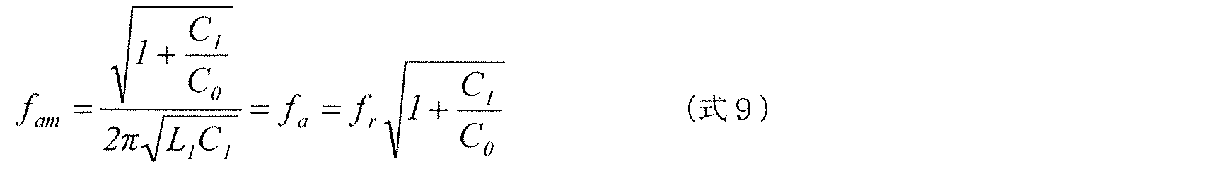
次に、共振子reso1にLC並列共振回路が直列接続された場合の共振特性について、等価回路モデルを用いて説明しておく。


このような共振解析に基づき、上述した実施例1及び実施例2において、スイッチ22SWのオン及びオフの切り替えに応じて並列腕回路12の共振周波数あるいは反共振周波数が切り替わることが説明される。
ここまで、周波数可変機能を有する高周波フィルタ回路として、第1インピーダンス素子としてキャパシタを用いて、第2インピーダンス素子としてインダクタを用いた構成を例に説明した。しかし、これらの関係は逆であってもかまわない。そこで、本実施の形態に係る周波数可変機能を有する高周波フィルタ回路の変形例として、このような構成について説明する。

(I-ii)スイッチ22SWがオフの場合の並列腕回路12Dのインピーダンス特性(図中の「並列腕回路12D(スイッチ22SW:Off)」)
(I-iii)スイッチ22SWがオンの場合のインピーダンス回路13Dのインピーダンス特性(図中の「インピーダンス回路13D(スイッチ22SW:On)」)
(I-iv)直列腕共振子22sのインピーダンス特性、すなわち直列腕回路11のインピーダンス特性(図中の「直列腕共振子22s」)
(I-v)並列腕共振子22pのインピーダンス特性(図中の「並列腕共振子22p」)
(II-ii)スイッチ22SWがオフの場合におけるフィルタ22Dの通過特性(図中の「スイッチ22SW:Off」)
ここで、上述のような並列腕回路12Dの共振周波数及び反共振周波数が得られる原理について、共振子の等価回路モデルを用いたインピーダンス特性(共振特性)の解析(共振解析)により説明しておく。
まず、共振子reso1にインダクタが直列接続された場合の共振特性について、等価回路モデルを用いて説明しておく。


このような共振解析に基づき、上述した実施例3及び実施例4において、スイッチ22SWのオン及びオフの切り替えに応じて並列腕回路12の共振周波数あるいは反共振周波数、及び、これらの数が切り替わることが説明される。
以上、実施の形態1及びその変形例に係るフィルタ22A及び22D(高周波フィルタ回路)について、説明した。以下では、このようなフィルタ22A及び22Dによって奏される効果について、説明する。
上記実施の形態1及びその変形例では、スイッチ素子と第2インピーダンス素子とで構成される第1直列回路14及び14Dを1つ備えるフィルタについて説明した。これに対して、実施の形態2では、当該第1直列回路を複数備えるフィルタについて説明する。
上記実施の形態2では、第1インピーダンス素子としてキャパシタを用い、第2インピーダンス素子としてインダクタを用いたフィルタを例に説明した。しかし、これらの関係は逆であってもかまわない。つまり、第1インピーダンス素子としてインダクタを用い、第2インピーダンス素子としてキャパシタを用いてもかまわない。そこで、実施の形態2の変形例1では、このようなフィルタについて説明する。
上記実施の形態2及びその変形例1では、スイッチ素子と第2インピーダンス素子とで構成される第1直列回路を複数備えるフィルタについて説明した。これに対して、実施の形態2の変形例2では、さらに、スイッチ素子と第3インピーダンス素子とで構成される第2直列回路を備えるフィルタについて説明する。
上記実施の形態2の変形例2では、第1インピーダンス素子及び第3インピーダンス素子としてキャパシタを用い、第2インピーダンス素子としてインダクタを用いたフィルタを例に説明した。しかし、これらの関係は逆であってもかまわない。つまり、第1インピーダンス素子及び第3インピーダンス素子としてインダクタを用い、第2インピーダンス素子としてキャパシタを用いてもかまわない。そこで、実施の形態2の変形例3では、このようなフィルタについて説明する。
上記実施の形態1及び2ならびにその変形例では、1つの直列腕回路と1つの並列腕回路とで構成されるラダー型のフィルタ構造を有するフィルタを例に説明した。しかし、フィルタは、少なくとも2つの当該並列腕回路と、少なくとも1つの当該直列腕回路と、で構成されるラダー型のフィルタ構造を有してもかまわない。そこで、実施の形態3では、このようなフィルタについて、4つの直列腕回路と4つの並列腕回路とで構成された、Band11、Band21及びBand32それぞれの受信帯域に対応するダイバーシティ用チューナブルフィルタを例に説明する。
実施の形態3で説明したフィルタ22Iは、実施の形態1に係る高周波フロントエンド回路2よりも、さらに使用バンド数が多いシステムに対応する高周波フロントエンド回路に適用することもできる。そこで、本実施の形態では、このような高周波フロントエンド回路について説明する。
また、上記説明した周波数可変機能を有するフィルタは、当該フィルタを含む複数のフィルタを備えるマルチプレクサに適用することができる。そこで、本実施の形態では、このようなマルチプレクサについて、Band11、Band21及びBand32の受信帯域に対応するフィルタと、Band1の受信帯域に対応するフィルタと、を備える構成を例に説明する。
以上、本発明の実施の形態に係る高周波フィルタ回路及び高周波フロントエンド回路について、実施の形態1~5及び変形例を挙げて説明したが、本発明は、上記実施の形態及び変形例に限定されるものではない。上記実施の形態及び変形例における任意の構成要素を組み合わせて実現される別の実施の形態や、上記実施の形態に対して本発明の主旨を逸脱しない範囲で当業者が思いつく各種変形を施して得られる変形例や、本発明に係る高周波フィルタ回路及び高周波フロントエンド回路を内蔵した各種機器も本発明に含まれる。
2、2L 高周波フロントエンド回路
3 RFIC(RF信号処理回路)
4 通信装置
10 ダイプレクサ
11 直列腕回路
12、12D 並列腕回路
13、13D インピーダンス回路
14、14D 第1直列回路
22A、22B、22D~22I、23A、23B フィルタ(高周波フィルタ回路)
22C、22Ca、22C(k-1)、22Ck、222Ca、222Cb、223Cb、224Cb キャパシタ
22L、22La、22Lb、22Lk、221L~224L インダクタ
22m 入出力端子(第1入出力端子)
22n 入出力端子(第2入出力端子)
22SW、22SWa、22SWb、22SW(k-1)、22SWk、221SWa~224SWa、221SWb~224SWb スイッチ(スイッチ素子)
22p、221p~224p 並列腕共振子
22s、221s~223s 直列腕共振子
24 送信増幅回路
26、261~263 受信増幅回路
30 接続回路
31 モジュール基板
32 弾性波共振子用パッケージ
33A、33B スイッチIC
34A、34B チップ部品
35 封止部材
100 圧電基板
101 密着層
102 主電極層
103 保護層
110a、110b 電極指
110c 共通端子
111a、111b バスバー電極
120、130 入出力端子
120A、120D~120F、120Z、121G~123G 並列腕回路
210a、210b スイッチ群
220 フィルタ群
251、253 受信側スイッチ(スイッチ回路)
ANT アンテナ端子
MPX マルチプレクサ
Tx、Tx1、Tx2 送信端子
Rx、Rx1、Rx2 受信端子
Claims (16)
- 第1入出力端子と第2入出力端子との間に接続された直列腕回路と、
前記第1入出力端子と前記第2入出力端子とを結ぶ経路上のノードとグランドとに接続された並列腕回路と、を備え、
前記並列腕回路は、
並列腕共振子と、前記並列腕共振子に直列接続されたインピーダンス回路とを備え、
前記インピーダンス回路は、
インダクタ及びキャパシタの一方である第1インピーダンス素子と、
インダクタ及びキャパシタの他方である第2インピーダンス素子と、
前記第2インピーダンス素子に直列接続されたスイッチ素子と、を備え、
前記第2インピーダンス素子及び前記スイッチ素子によって構成される第1直列回路は、前記第1インピーダンス素子に並列接続されている、
高周波フィルタ回路。 - 前記第1インピーダンス素子がキャパシタ、かつ、前記第2インピーダンス素子がインダクタである、
請求項1に記載の高周波フィルタ回路。 - 前記スイッチ素子が導通である場合には、前記インピーダンス回路のインピーダンスが極大となる周波数が、前記並列腕共振子の共振周波数より高い、
請求項2に記載の高周波フィルタ回路。 - 前記スイッチ素子が導通である場合には、前記インピーダンス回路のインピーダンスが極大となる周波数が、前記並列腕共振子の共振周波数より低い、
請求項2に記載の高周波フィルタ回路。 - 前記第1インピーダンス素子がインダクタ、かつ、前記第2インピーダンス素子がキャパシタである、
請求項1に記載の高周波フィルタ回路。 - 前記スイッチ素子が導通である場合には、前記インピーダンス回路のインピーダンスが極大となる周波数が、前記並列腕共振子の共振周波数より低い、
請求項5に記載の高周波フィルタ回路。 - 前記スイッチ素子が導通である場合には、前記インピーダンス回路のインピーダンスが極大となる周波数が、前記並列腕共振子の共振周波数より高い、
請求項5に記載の高周波フィルタ回路。 - さらに、
インダクタ及びキャパシタの一方である第3インピーダンス素子と、
前記第3インピーダンス素子に直列接続されたスイッチ素子と、を備え、
前記第3インピーダンス素子及び当該スイッチ素子によって構成される第2直列回路は、前記第1インピーダンス素子に並列接続されている、
請求項1~7のいずれか1項に記載の高周波フィルタ回路。 - 少なくとも2つの前記並列腕回路と、
少なくとも1つの前記直列腕回路と、
で構成されるラダー型のフィルタ構造を有する、
請求項1~8のいずれか1項に記載の高周波フィルタ回路。 - 少なくとも2つの前記並列腕回路の各々において、前記第1インピーダンス素子がキャパシタ、かつ、前記第2インピーダンス素子がインダクタである、
請求項9に記載の高周波フィルタ回路。 - 少なくとも2つの前記並列腕回路の各々において、前記第1インピーダンス素子がインダクタ、かつ、前記第2インピーダンス素子がキャパシタである、
請求項9に記載の高周波フィルタ回路。 - 少なくとも2つの前記並列腕回路のうち一部の並列腕回路において、前記第1インピーダンス素子がキャパシタ、かつ、前記第2インピーダンス素子がインダクタであり、
他の並列腕回路において、前記第1インピーダンス素子がインダクタ、かつ、前記第2インピーダンス素子がキャパシタである、
請求項9に記載の高周波フィルタ回路。 - 第1入出力端子と第2入出力端子との間に接続された直列腕共振子と、
前記第1入出力端子と前記第2入出力端子とを結ぶ経路上のノードとグランドとの間に接続された並列腕共振子と、
インダクタ及びキャパシタの一方であって、前記ノードと前記グランドとの間で前記並列腕共振子に直列接続された第1インピーダンス素子と、
インダクタ及びキャパシタの他方である第2インピーダンス素子と、
前記第2インピーダンス素子に直列接続されたスイッチ素子と、を備え、
前記第2インピーダンス素子及び前記スイッチ素子によって構成される第1直列回路は、前記第1インピーダンス素子に並列接続されている、
高周波フィルタ回路。 - 請求項1~13のいずれか1項に記載の高周波フィルタ回路を含む複数の高周波フィルタ回路と、
前記複数の高周波フィルタ回路の前段及び後段の少なくとも一方に設けられ、前記複数の高周波フィルタ回路と個別に接続された複数の選択端子、及び、前記複数の選択端子と選択的に接続される共通端子を有するスイッチ回路と、を備える、
高周波フロントエンド回路。 - 請求項1~13のいずれか1項に記載の高周波フィルタ回路と、
前記スイッチ素子の導通及び非導通を制御する制御部と、を備える、
高周波フロントエンド回路。 - アンテナ素子で送受信される高周波信号を処理するRF信号処理回路と、
前記アンテナ素子と前記RF信号処理回路との間で前記高周波信号を伝達する請求項14または15に記載の高周波フロントエンド回路と、を備える、
通信装置。
Priority Applications (4)
| Application Number | Priority Date | Filing Date | Title |
|---|---|---|---|
| JP2018519646A JP6669252B2 (ja) | 2016-05-27 | 2017-05-26 | 高周波フィルタ回路、高周波フロントエンド回路及び通信装置 |
| KR1020187033844A KR102115113B1 (ko) | 2016-05-27 | 2017-05-26 | 고주파 필터 회로, 고주파 프런트 엔드 회로 및 통신 장치 |
| CN201780032938.3A CN109196778B (zh) | 2016-05-27 | 2017-05-26 | 高频滤波电路、高频前端电路以及通信装置 |
| US16/199,362 US11476835B2 (en) | 2016-05-27 | 2018-11-26 | High-frequency filter circuit, high-frequency front end circuit, and communication device |
Applications Claiming Priority (2)
| Application Number | Priority Date | Filing Date | Title |
|---|---|---|---|
| JP2016-106802 | 2016-05-27 | ||
| JP2016106802 | 2016-05-27 |
Related Child Applications (1)
| Application Number | Title | Priority Date | Filing Date |
|---|---|---|---|
| US16/199,362 Continuation US11476835B2 (en) | 2016-05-27 | 2018-11-26 | High-frequency filter circuit, high-frequency front end circuit, and communication device |
Publications (1)
| Publication Number | Publication Date |
|---|---|
| WO2017204348A1 true WO2017204348A1 (ja) | 2017-11-30 |
Family
ID=60411787
Family Applications (1)
| Application Number | Title | Priority Date | Filing Date |
|---|---|---|---|
| PCT/JP2017/019792 WO2017204348A1 (ja) | 2016-05-27 | 2017-05-26 | 高周波フィルタ回路、高周波フロントエンド回路及び通信装置 |
Country Status (5)
| Country | Link |
|---|---|
| US (1) | US11476835B2 (ja) |
| JP (1) | JP6669252B2 (ja) |
| KR (1) | KR102115113B1 (ja) |
| CN (1) | CN109196778B (ja) |
| WO (1) | WO2017204348A1 (ja) |
Cited By (2)
| Publication number | Priority date | Publication date | Assignee | Title |
|---|---|---|---|---|
| JP2020028013A (ja) * | 2018-08-10 | 2020-02-20 | 株式会社村田製作所 | フィルタおよびマルチプレクサ |
| US20210306018A1 (en) * | 2020-03-31 | 2021-09-30 | Murata Manufacturing Co., Ltd. | Radio frequency module and communication device |
Families Citing this family (4)
| Publication number | Priority date | Publication date | Assignee | Title |
|---|---|---|---|---|
| WO2017204347A1 (ja) * | 2016-05-27 | 2017-11-30 | 株式会社村田製作所 | 高周波フィルタ装置、及び、通信装置 |
| WO2019073899A1 (ja) * | 2017-10-10 | 2019-04-18 | 株式会社村田製作所 | マルチプレクサおよび高周波フィルタ |
| JP2021087035A (ja) | 2019-11-25 | 2021-06-03 | 株式会社村田製作所 | 高周波信号送受信回路 |
| US20220200645A1 (en) * | 2020-12-18 | 2022-06-23 | Skyworks Solutions, Inc. | Stacked resonator based antennaplexer |
Citations (7)
| Publication number | Priority date | Publication date | Assignee | Title |
|---|---|---|---|---|
| JPH09321573A (ja) * | 1996-05-27 | 1997-12-12 | Toshiba Corp | 弾性表面波フィルタ装置 |
| JPH10163808A (ja) * | 1996-11-29 | 1998-06-19 | Oki Electric Ind Co Ltd | 有極型sawフィルタ |
| JP2000323961A (ja) * | 1999-03-10 | 2000-11-24 | Matsushita Electric Ind Co Ltd | 弾性表面波共振器を用いた帯域切替フィルタとそれを用いたアンテナ共用器 |
| JP2008205947A (ja) * | 2007-02-21 | 2008-09-04 | Ngk Insulators Ltd | ラダー型圧電フィルタ |
| JP2008306359A (ja) * | 2007-06-06 | 2008-12-18 | Mitsubishi Electric Corp | ハイパスフィルタ内蔵スイッチ、ハイパスフィルタ/ローパスフィルタ切替型移相器、可変共振器、通過帯域可変バンドパスフィルタ、阻止帯域可変バンドリジェクトフィルタ |
| JP2009207116A (ja) * | 2008-01-31 | 2009-09-10 | Fujitsu Ltd | 弾性波デバイス、デュープレクサ、通信モジュール、および通信装置 |
| US20090251235A1 (en) * | 2008-02-15 | 2009-10-08 | Stmicroelectronics S.A. | Bulk acoustic wave resonator filter being digitally reconfigurable, with process |
Family Cites Families (15)
| Publication number | Priority date | Publication date | Assignee | Title |
|---|---|---|---|---|
| JP2000114873A (ja) | 1998-09-29 | 2000-04-21 | Seiko Epson Corp | Saw発振器の温度補償方法、温度補償型saw発振器、並びにその発振器を用いた送信機および受信機 |
| EP1035648A3 (en) | 1999-03-10 | 2000-12-27 | Matsushita Electric Industrial Co., Ltd. | A band switching filter using a surface acoustic wave resonator and an antenna duplexer using the same |
| DE10127655A1 (de) * | 2001-06-07 | 2003-01-02 | Infineon Technologies Ag | BAW-Filteranordnung |
| JP3822470B2 (ja) | 2001-08-17 | 2006-09-20 | Tdk株式会社 | 圧電共振子、フィルタ、デュプレクサならびに圧電共振子の共振周波数調整方法 |
| JP2008054046A (ja) * | 2006-08-24 | 2008-03-06 | Matsushita Electric Ind Co Ltd | 圧電フィルタ及びそれを用いた共用器、通信機器 |
| JP4979897B2 (ja) * | 2005-05-25 | 2012-07-18 | 太陽誘電株式会社 | 弾性波フィルタおよび弾性波分波器 |
| CN201234137Y (zh) * | 2008-07-25 | 2009-05-06 | 西安爱科电子有限责任公司 | 可变换参数的高通滤波器 |
| CN102725959B (zh) * | 2010-01-28 | 2016-05-25 | 株式会社村田制作所 | 可调谐滤波器 |
| JP2012039465A (ja) * | 2010-08-09 | 2012-02-23 | Panasonic Corp | 携帯無線機 |
| US20130214979A1 (en) * | 2012-02-17 | 2013-08-22 | Emily B. McMilin | Electronic Device Antennas with Filter and Tuning Circuitry |
| CN103296907B (zh) * | 2012-03-02 | 2015-05-06 | 台达电子企业管理(上海)有限公司 | 多重化逆变器及有源电力滤波系统 |
| CN103259501B (zh) * | 2013-05-31 | 2016-06-29 | 电子科技大学 | 一种通信系统用带阻滤波器 |
| WO2015045794A1 (ja) * | 2013-09-26 | 2015-04-02 | 株式会社村田製作所 | 共振器及び高周波フィルタ |
| JP6187593B2 (ja) * | 2013-09-26 | 2017-08-30 | 株式会社村田製作所 | 共振回路及び高周波フィルタ |
| JP6638214B2 (ja) * | 2015-05-14 | 2020-01-29 | 株式会社村田製作所 | 可変フィルタ回路、および、高周波モジュール |
-
2017
- 2017-05-26 JP JP2018519646A patent/JP6669252B2/ja active Active
- 2017-05-26 WO PCT/JP2017/019792 patent/WO2017204348A1/ja active Application Filing
- 2017-05-26 KR KR1020187033844A patent/KR102115113B1/ko active IP Right Grant
- 2017-05-26 CN CN201780032938.3A patent/CN109196778B/zh active Active
-
2018
- 2018-11-26 US US16/199,362 patent/US11476835B2/en active Active
Patent Citations (7)
| Publication number | Priority date | Publication date | Assignee | Title |
|---|---|---|---|---|
| JPH09321573A (ja) * | 1996-05-27 | 1997-12-12 | Toshiba Corp | 弾性表面波フィルタ装置 |
| JPH10163808A (ja) * | 1996-11-29 | 1998-06-19 | Oki Electric Ind Co Ltd | 有極型sawフィルタ |
| JP2000323961A (ja) * | 1999-03-10 | 2000-11-24 | Matsushita Electric Ind Co Ltd | 弾性表面波共振器を用いた帯域切替フィルタとそれを用いたアンテナ共用器 |
| JP2008205947A (ja) * | 2007-02-21 | 2008-09-04 | Ngk Insulators Ltd | ラダー型圧電フィルタ |
| JP2008306359A (ja) * | 2007-06-06 | 2008-12-18 | Mitsubishi Electric Corp | ハイパスフィルタ内蔵スイッチ、ハイパスフィルタ/ローパスフィルタ切替型移相器、可変共振器、通過帯域可変バンドパスフィルタ、阻止帯域可変バンドリジェクトフィルタ |
| JP2009207116A (ja) * | 2008-01-31 | 2009-09-10 | Fujitsu Ltd | 弾性波デバイス、デュープレクサ、通信モジュール、および通信装置 |
| US20090251235A1 (en) * | 2008-02-15 | 2009-10-08 | Stmicroelectronics S.A. | Bulk acoustic wave resonator filter being digitally reconfigurable, with process |
Cited By (3)
| Publication number | Priority date | Publication date | Assignee | Title |
|---|---|---|---|---|
| JP2020028013A (ja) * | 2018-08-10 | 2020-02-20 | 株式会社村田製作所 | フィルタおよびマルチプレクサ |
| US20210306018A1 (en) * | 2020-03-31 | 2021-09-30 | Murata Manufacturing Co., Ltd. | Radio frequency module and communication device |
| US11528044B2 (en) * | 2020-03-31 | 2022-12-13 | Murata Manufacturing Co., Ltd. | Radio frequency module and communication device |
Also Published As
| Publication number | Publication date |
|---|---|
| KR102115113B1 (ko) | 2020-05-25 |
| US11476835B2 (en) | 2022-10-18 |
| US20190097605A1 (en) | 2019-03-28 |
| JPWO2017204348A1 (ja) | 2019-03-14 |
| CN109196778B (zh) | 2022-06-14 |
| CN109196778A (zh) | 2019-01-11 |
| KR20180133923A (ko) | 2018-12-17 |
| JP6669252B2 (ja) | 2020-03-18 |
Similar Documents
| Publication | Publication Date | Title |
|---|---|---|
| CN108604893B (zh) | 高频滤波电路、双工器、高频前端电路以及通信装置 | |
| JP6669262B2 (ja) | 弾性波フィルタ装置、高周波フロントエンド回路及び通信装置 | |
| CN109643987B (zh) | 弹性波滤波器装置、多工器、高频前端电路以及通信装置 | |
| WO2017204348A1 (ja) | 高周波フィルタ回路、高周波フロントエンド回路及び通信装置 | |
| JP6669263B2 (ja) | 弾性波フィルタ装置、高周波フロントエンド回路及び通信装置 | |
| US10944381B2 (en) | Acoustic wave filter device, multiplexer, radio-frequency front end circuit, and communication device | |
| CN109196777B (zh) | 高频滤波电路、多工器、高频前端电路以及通信装置 | |
| US11115002B2 (en) | Multiplexer, radio frequency front-end circuit, and communication device | |
| US10958242B2 (en) | Acoustic wave filter device, multiplexer, radio-frequency front end circuit, and communication device | |
| WO2018052073A1 (ja) | 弾性波フィルタ装置、マルチプレクサ、高周波フロントエンド回路及び通信装置 | |
| US10819310B2 (en) | Radio-frequency filter circuit, multiplexer, radio-frequency front-end circuit, and communication apparatus | |
| KR102193508B1 (ko) | 탄성파 필터 장치, 고주파 프론트엔드 회로 및 통신 장치 | |
| CN109643989B (zh) | 弹性波滤波器装置、高频前端电路以及通信装置 | |
| US11394368B2 (en) | Acoustic wave filter, multiplexer, radio frequency front-end circuit, and communication device | |
| WO2018186227A1 (ja) | 弾性波フィルタ装置、デュプレクサ、高周波フロントエンド回路、および通信装置 |
Legal Events
| Date | Code | Title | Description |
|---|---|---|---|
| ENP | Entry into the national phase |
Ref document number: 2018519646 Country of ref document: JP Kind code of ref document: A |
|
| ENP | Entry into the national phase |
Ref document number: 20187033844 Country of ref document: KR Kind code of ref document: A |
|
| NENP | Non-entry into the national phase |
Ref country code: DE |
|
| 121 | Ep: the epo has been informed by wipo that ep was designated in this application |
Ref document number: 17802934 Country of ref document: EP Kind code of ref document: A1 |
|
| 122 | Ep: pct application non-entry in european phase |
Ref document number: 17802934 Country of ref document: EP Kind code of ref document: A1 |