WO2017203987A1 - パラメータ同定装置、モータ制御システム、パラメータ同定方法及びプログラム - Google Patents
パラメータ同定装置、モータ制御システム、パラメータ同定方法及びプログラム Download PDFInfo
- Publication number
- WO2017203987A1 WO2017203987A1 PCT/JP2017/017827 JP2017017827W WO2017203987A1 WO 2017203987 A1 WO2017203987 A1 WO 2017203987A1 JP 2017017827 W JP2017017827 W JP 2017017827W WO 2017203987 A1 WO2017203987 A1 WO 2017203987A1
- Authority
- WO
- WIPO (PCT)
- Prior art keywords
- motor
- load
- angle
- model
- torque
- Prior art date
- Legal status (The legal status is an assumption and is not a legal conclusion. Google has not performed a legal analysis and makes no representation as to the accuracy of the status listed.)
- Ceased
Links
Images






Classifications
-
- G—PHYSICS
- G05—CONTROLLING; REGULATING
- G05B—CONTROL OR REGULATING SYSTEMS IN GENERAL; FUNCTIONAL ELEMENTS OF SUCH SYSTEMS; MONITORING OR TESTING ARRANGEMENTS FOR SUCH SYSTEMS OR ELEMENTS
- G05B11/00—Automatic controllers
- G05B11/01—Automatic controllers electric
- G05B11/32—Automatic controllers electric with inputs from more than one sensing element; with outputs to more than one correcting element
-
- G—PHYSICS
- G05—CONTROLLING; REGULATING
- G05B—CONTROL OR REGULATING SYSTEMS IN GENERAL; FUNCTIONAL ELEMENTS OF SUCH SYSTEMS; MONITORING OR TESTING ARRANGEMENTS FOR SUCH SYSTEMS OR ELEMENTS
- G05B19/00—Program-control systems
- G05B19/02—Program-control systems electric
- G05B19/18—Numerical control [NC], i.e. automatically operating machines, in particular machine tools, e.g. in a manufacturing environment, so as to execute positioning, movement or co-ordinated operations by means of program data in numerical form
- G05B19/19—Numerical control [NC], i.e. automatically operating machines, in particular machine tools, e.g. in a manufacturing environment, so as to execute positioning, movement or co-ordinated operations by means of program data in numerical form characterised by positioning or contouring control systems, e.g. to control position from one programmed point to another or to control movement along a programmed continuous path
-
- G—PHYSICS
- G05—CONTROLLING; REGULATING
- G05B—CONTROL OR REGULATING SYSTEMS IN GENERAL; FUNCTIONAL ELEMENTS OF SUCH SYSTEMS; MONITORING OR TESTING ARRANGEMENTS FOR SUCH SYSTEMS OR ELEMENTS
- G05B23/00—Testing or monitoring of control systems or parts thereof
- G05B23/02—Electric testing or monitoring
-
- H—ELECTRICITY
- H02—GENERATION; CONVERSION OR DISTRIBUTION OF ELECTRIC POWER
- H02P—CONTROL OR REGULATION OF ELECTRIC MOTORS, ELECTRIC GENERATORS OR DYNAMO-ELECTRIC CONVERTERS; CONTROLLING TRANSFORMERS, REACTORS OR CHOKE COILS
- H02P21/00—Arrangements or methods for the control of electric machines by vector control, e.g. by control of field orientation
- H02P21/14—Estimation or adaptation of machine parameters, e.g. flux, current or voltage
Definitions
- the present invention relates to a parameter identification device, a motor control system, a parameter identification method, and a program.
- the moment of inertia J, the viscosity coefficient D, and the Coulomb friction coefficient ⁇ f of the entire controlled object are calculated by a predetermined error system when the entire controlled object is imitated as a single inertia system model. Identification based on the error signal and its internal signal.
- Patent Document 1 as a model parameter estimation means, the stiffness and the magnitude of friction at the time of saturation are estimated from the displacement-deformation phase plane (lost motion correction model), and the lost motion correction amount is calculated. A method is disclosed.
- Patent Document 2 discloses a method of obtaining each model parameter from the measurement result of the attachment and the measurement result of the relationship between the force and the displacement by the force measuring device and using it for the timing of the lost motion correction.
- Actual control target may have a portion (connecting member) having a weak rigidity and a play (dead band) in a power transmission system from the motor to the load.
- a control object can construct a more accurate model by adopting a two-inertia system model that is divided into a motor side and a load side, with the portion having the weak rigidity and backlash as a boundary. it can.
- An object of the present invention is made in view of the above problems, and is a parameter identification device, a motor control system, a parameter identification method, and a program that can obtain a model that accurately simulates a mechanical system having a motor and a load. It is to provide.
- a parameter identification device is a parameter identification device that identifies a model parameter of a two-inertia system model simulating a mechanical system in which a motor and a load are coupled by a coupling member,
- a data acquisition unit for acquiring a torque command value for the motor, measured data of the motor angle and angular velocity, measured data of the load angle and angular velocity, the acquired torque command value, and the angle of the motor
- a phase plane diagram generating unit that generates a plurality of phase plane diagrams based on the actual measurement data of the angular velocity and the angular data of the load and the angular velocity, and based on the generated plurality of the phase plane diagrams
- a parameter identification unit that identifies model parameters indicating motor friction, load friction, rigidity of the coupling member, and dead band width of the coupling member.
- the phase surface diagram generation unit generates a torque-torsion speed phase surface diagram indicating the relationship between the torque command value and the torsion speed of the connecting member as the phase surface diagram.
- the parameter identification unit identifies a model parameter indicating the friction of the motor based on the position of the break point in the torque-torsion phase diagram.
- the phase plane diagram generation unit includes a twist angle-torsion speed phase plane indicating a relationship between a twist angle of the connecting member and a twist speed of the connecting member as the phase plane diagram.
- a parameter is generated, and the parameter identifying unit identifies model parameters indicating the rigidity of the connecting member and the dead band width of the connecting member based on the position of the break point in the twist angle-torsion speed phase diagram.
- the phase plane diagram generation unit as the phase plane diagram, has a relationship between the torque command value and at least one of the angular velocity of the motor and the angular velocity of the load.
- a torque-mechanical angular velocity phase diagram is generated, and the parameter identification unit identifies a model parameter indicating the friction of the load based on the position of the break point in the torque-mechanical angular velocity phase diagram.
- the phase plane diagram generation unit generates a load angle-torque phase plane diagram indicating the relationship between the load angle and the torque command value as the phase plane diagram
- the parameter identification unit identifies a model parameter indicating friction of the load based on a position of a break point in the load angle-torque phase diagram.
- the phase plane diagram generation unit generates a twist angle-torque phase plane diagram showing a relationship between a twist angle of the connecting member and the torque command value as the phase plane diagram.
- the parameter identification unit is configured to determine the friction of the motor, the friction of the load, the rigidity of the connecting member, and the dead band width of the connecting member based on the position of the break point in the twist angle-torque phase diagram. A model parameter indicating at least one of them is identified.
- a motor-side model of the two-inertia system model with respect to the motor based on the torque command value, the motor angle, and the measured data of the load angle.
- the load-side model of the two-inertia system model Based on the motor-side error system that outputs a motor-side error signal indicating the degree of error, and the measured data of the motor angle and the load angle, the load-side model of the two-inertia system model, A load-side error system that outputs a load-side error signal indicating a degree of error with respect to the load, wherein the parameter identification unit inputs the motor-side error signal and at least calculates the inertia moment and viscosity coefficient of the motor. Identify the model parameters to be shown and input the load side error signal to show at least the inertia moment and viscosity coefficient of the load To identify the Dell parameters.
- the parameter identification unit includes the torque command value acquired when the amplitude and frequency of the repetitive motion performed by the mechanical system are relatively small amplitude and low frequency, and the Based on the measured data of the motor angle and angular velocity and the measured data of the load angle and angular velocity, the motor friction, the load friction, the rigidity of the connecting member, and the dead band width of the connecting member are calculated.
- the torque command value acquired when the amplitude and frequency of the repetitive motion performed by the mechanical system are relatively large and high frequency, the measured data of the angle of the motor, and the load Model parameters indicating the moment of inertia and viscosity coefficient of the motor, and a model indicating the moment of inertia and viscosity coefficient of the load based on the measured data of the angle of To identify the parameters.
- the parameter identification device is a parameter identification device that identifies a model parameter of a two-inertia system model imitating a mechanical system in which a motor and a load are coupled by a coupling member.
- a data acquisition unit for acquiring a torque command value for the motor, measured data for the angle of the motor, and measured data for the angle of the load, the acquired torque command value, and measured the angle of the motor A phase plane diagram generation unit that generates a torsion angle-torque phase plane diagram showing a relationship between the torsion angle of the connecting member and the torque command value based on the data and the actual measurement data of the load angle; A model parameter indicating the friction of the motor, the friction of the load, the rigidity of the connecting member, and the dead band width of the connecting member based on the twist angle-torque phase diagram. Includes a parameter identification unit for identifying over data, the.
- the motor control system provides feedback for calculating the torque command value based on the parameter identification device described above and a deviation of a current angle with respect to a target angle of the load.
- the parameter identification method is a parameter identification method for identifying a model parameter of a two-inertia system model imitating a mechanical system in which a motor and a load are coupled by a coupling member.
- the program includes a computer of a parameter identification device that identifies a model parameter of a two-inertia system model simulating a mechanical system in which a motor and a load are coupled by a coupling member.
- FIG. 1 is a diagram illustrating an outline of a mechanical system to be controlled by the motor control system according to the first embodiment.
- the motor control system 1 according to the first embodiment includes a motor 20, a load 21, and a shaft 22 (connection member) that mechanically connects the motor 20 and the load 21.
- This is a system for controlling the operation of the mechanical system 2.
- the motor 20 is a servo motor that has a rotation detector (encoder) capable of detecting a rotation angle and a rotation speed therein and can realize precise positioning.
- the shaft 22 is a member having, for example, a rigid element such as a ball screw and a gear, and a backlash element.
- the motor control system 1 receives an angle command value indicating a target rotation angle of the load 21 (hereinafter referred to as “target angle ⁇ t ”) from a host device (host controller) (not shown). Then, the motor control system 1 calculates a torque tau to be generated in the motor 20 in accordance with the target angle theta t accepted, and outputs a torque command value indicating the torque tau.
- the motor 20 is rotationally driven with a torque ⁇ based on the received torque command value, and the torque ⁇ is transmitted from the motor 20 side to the load 21 side through the shaft 22.
- the load 21 is rotationally driven according to the transmitted torque ⁇ ′. In this way, the motor control system 1, the rotation angle theta L of the load 21 is controlled to conform to the desired target angle theta t is achieved.
- the motor control system 1 is a so-called closed system, and inputs actual measurement data indicating the rotation speed (angular speed) of the motor 20 and the rotation angle of the load 21, and based on these measurement data. Perform feedback control.
- the rotational speed (angular speed) of the motor 20 is also referred to as “motor angular speed ⁇ M ”, and the rotational angle of the motor 20 is also referred to as “motor angle ⁇ M ”.
- the rotational speed (angular speed) of the load 21 is also referred to as “load angular speed ⁇ L ”
- the rotational angle of the load 21 is also referred to as “load angle ⁇ L ”.
- the motor control system 1 further has a two-inertia system model (described later) imitating the mechanical system 2 as a two-inertia system in advance, and performs feedforward control based on the two-inertia system model.
- the control target parameter for the load 21 is not strictly “angle” or “angular velocity” but “position”. ",” Speed ".
- the motor control system 1 handles the same dimension as the “angle” and “angular velocity” of the motor 20 as a two-inertia system, the “position” and “speed” of the load are used as motor shaft conversion values.
- Various control is performed by sequentially converting to “angle” and “angular velocity”.
- the parameter group representing the characteristics unique to the mechanical system 2 includes a parameter indicating the characteristics on the motor 20 side, a parameter indicating the characteristics on the load 21 side, and the motor 20 and the load.
- 21 is roughly divided into parameters indicating the characteristics of the shaft 22 (connection member) that mechanically connects the shaft 21 and transmits power.
- parameters indicating characteristics on the motor 20 side there are a motor-side moment of inertia J M , a motor-side viscosity coefficient D M , and a motor-side friction coefficient ⁇ fM .
- FIG. 2 is a block diagram of the mechanical system according to the first embodiment.
- the mechanical system 2 see FIG. 1 according to the present embodiment as a two-inertia system including the motor 20, the load 21 and the shaft 22, the relationship between input and output in the mechanical system 2 is as shown in FIG. It can be represented by a block diagram using a transfer function.
- the motor 20 receives the torque ⁇ generated based on the torque command value received from the motor control system 1 (FIG. 1), and outputs the motor angular velocity ⁇ M and the motor angle ⁇ M. .
- the torque ⁇ input to the motor 20 is obtained by subtracting the motor side friction coefficient ⁇ fM , which is the friction generated in the motor 20, and the torque ⁇ ′ transmitted to the load 21 through the shaft 22, and then the transmission element 1 / (J M
- the motor angular velocity ⁇ M is converted through s + D M ), and further the motor angle ⁇ M is converted through the transmission element 1 / s.
- the motor side friction coefficient tau fM is only the sign of the speed when reversing the motor 20 (sign inversion when the motor angular velocity omega M) not only Coulomb friction component for inverting the speed after inversion of the displacement of the motor 20 (motor It includes a nonlinear friction component that varies nonlinearly depending on the angular velocity ⁇ M (integral value from zero).
- Motor side friction coefficient tau fM defines a modeled nonlinear friction component, obtained through the motor-side friction function G M to an input variable motor angular velocity omega M. For more information on the motor side friction function G M will be described later.
- L be the output.
- the torque ⁇ ′ input to the load 21 is converted into the load angular velocity ⁇ L through the transmission element 1 / (J L s + D L ) after subtracting the load side friction coefficient ⁇ fL that is the friction generated in the load 21, and It is converted to the load angle theta L via transmission element 1 / s.
- the load side friction coefficient tau fL includes a non-linear frictional component varies nonlinearly depending on the speed after inversion of the displacement of the load 21 (an integral value from zero load the angular velocity omega L).
- Load side friction coefficient tau fL defines a modeled nonlinear friction component, obtained through the load side friction function G L to an input variable load angular velocity omega L. Details of the load side friction function GL will be described later.
- a rotation detector (encoder) (not shown) is installed in each of the motor 20 and the load 21 constituting the mechanical system 2.
- the motor control system 1 uses the rotation detector to measure actual data indicating changes over time of the motor angle ⁇ M and the load angle ⁇ L , and the motor angular velocity ⁇ M and the load angular velocity ⁇ L that can be derived from these time derivatives. Obtain actual measurement data showing changes over time.
- the shaft 22 receives a deviation between the motor angle ⁇ M and the load angle ⁇ L (hereinafter also referred to as “twist angle ( ⁇ M ⁇ L )”) as an input, and the twist angle
- This is a transmission system that outputs a torque ⁇ ′ according to ( ⁇ M ⁇ L ).
- the input twist angle ( ⁇ M ⁇ L ) is applied to the motor 20 and the load 21 through the dead zone characteristic function F1 representing nonlinearity in the dead zone (backlash), the transfer element K R and the transfer element D R s. Is converted to torque ⁇ ′.
- the dead zone characteristic function F1 nonlinear function twist angle of the axis 22 a ( ⁇ M - ⁇ L) as an input variable, and outputs a minus backlash displacement BKLS from the twist angle ( ⁇ M - ⁇ L) It is. Details of the dead zone characteristic function F1 will be described later.
- the torsional rigidity coefficient K R a parameter indicating the degree of stiffness of the torsion axis 22, which corresponds to the spring constant of the shaft 22. That is, the torsional rigidity coefficient K R, of the torque tau 'applied to the load 21, providing a component proportional to the twist angle of the axis 22 ( ⁇ M - ⁇ L).
- twist viscosity coefficient D R a parameter indicating the degree of stickiness of the shaft 22, of the torque tau 'applied to the load 21, the deviation between the motor angular velocity omega M in the shaft 22 and the load angular velocity omega L (Hereinafter also referred to as “twisting speed ( ⁇ M ⁇ L )”) is given.
- the motor-side inertia moment J M , the motor-side viscosity coefficient D M , the motor-side friction coefficient ⁇ fM , the load-side inertia moment J L , the load-side viscosity coefficient D L , and the load-side friction coefficient ⁇ fL , torsional rigidity coefficient K R, twist viscosity coefficient D R and the dead zone width BL is a parameter group representative of the actual characteristics of the mechanical system 2, both of which are unknown parameters observation is difficult to separate.
- the torque ⁇ that is an input to the mechanical system 2 and the motor angular velocity ⁇ M , the motor angle ⁇ M , the load angular velocity ⁇ L, and the load angle ⁇ L that are outputs are parameters that can be observed through the rotation detector described above. is there.
- FIG. 3 is a diagram illustrating the friction characteristics on the motor side and the load side of the mechanical system according to the first embodiment.
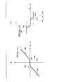
- FIG. 3A is a graph showing nonlinear friction characteristics generated in each of the motor side friction coefficient ⁇ fM and the load side friction coefficient ⁇ fL .
- the well-known Coulomb friction changes only in the direction (positive or negative sign) depending on the direction (positive or negative sign) of the object speed (motor angular speed ⁇ M , load angular speed ⁇ L ), The amount is known not to vary with respect to speed ( ⁇ ) and displacement ( ⁇ ).
- the shaft 22 includes rolling elements such as ball screws and ball bearings, it is necessary to consider “rolling friction” having characteristics different from those of ordinary Coulomb friction.
- the rolling friction is an apparent spring due to the displacement after the speed reversal (integral value from zero of the motor angular speed ⁇ M and the load angular speed ⁇ L ). It has a nonlinear spring characteristic whose constant changes dynamically, and draws a hysteresis curve as shown in FIG. This is considered to be due to elastic deformation and slip at the contact portion between the rolling element and the raceway surface. Further, in the “coarse motion region” where the rolling element rolls effectively, the static characteristic with respect to the friction speed is shown by Coulomb friction. That is, as shown in FIG.
- the friction of the motor 20 (motor-side friction coefficient ⁇ fM ) is saturated at the motor-side Coulomb friction coefficient ⁇ fMc when the displacement after the speed reversal becomes equal to or greater than a predetermined value.
- the friction of the load 21 (load-side friction coefficient ⁇ fL ) is saturated at the load-side Coulomb friction coefficient ⁇ fLc when the displacement after the speed reversal becomes equal to or greater than a predetermined value.
- the motor-side frictional characteristic function G M and the load side friction characteristic function G L is defined on the basis of a nonlinear frictional characteristic shown in FIG. 3 (a) to GMS model obtained by broken line approximation.
- the GMS model imitates a state in which N blocks having different characteristics (rolling elements) and a spring are connected in parallel.
- Each of a plurality of straight lines constituting the graph (polygonal line) shown in FIG. 3B represents how many of the N blocks are rolled (effectively rolling). is doing.
- the load side friction characteristic function G L is also defined similarly to the motor side friction characteristic function G M shown in FIG. 3 (b).
- FIG. 4 is a diagram for explaining the characteristics of the dead zone in the mechanical connection member according to the first embodiment.
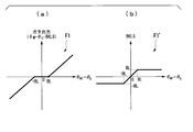
- a dead band characteristic function F1 shown in FIG. 4A represents a transfer characteristic based on a dead band width BL indicating the width of the “play” (dead band) of the shaft 22 provided between the motor 20 and the load 21. .
- the dead band characteristic function F1 is a nonlinear characteristic that depends on the dead band width BL, and the torsion angle ( ⁇ M ⁇ L ) of the shaft 22 is an input variable.
- the absolute value of the twist angle ( ⁇ M ⁇ L ) of the shaft 22 is equal to or less than the dead band width BL ( ⁇ BL ⁇ ⁇ M ⁇ L ⁇ + BL)
- the backlash output is zero. It becomes.
- the backlash displacement function F1 ′ shown in FIG. 4B has a relationship between the backlash displacement BKLS and the twist angle ( ⁇ M ⁇ L ).
- the backlash displacement BKLS is a parameter indicating the amount of displacement in the dead zone having a width of the dead zone width BL ( ⁇ BL to + BL). As shown in FIG. 4B with respect to the twist angle ( ⁇ M ⁇ L ). It has special characteristics. That is, the backlash output shown in FIG. 4A can be expressed as “ ⁇ M ⁇ L ⁇ BKLS” using the backlash displacement BKLS. As shown in FIG.
- the backlash displacement BKLS has a minimum value ( ⁇ BL) when the torsion angle ( ⁇ M ⁇ L ) is smaller than the minimum value ( ⁇ BL) of the dead zone.
- the backlash displacement BKLS takes the maximum value (+ BL).
- the backlash BKLS is the same as the twist angle ( ⁇ M ⁇ L ). The characteristic has a value.
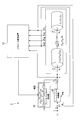
- FIG. 5 is a diagram illustrating a functional configuration of the motor control system according to the first embodiment.
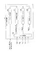
- the motor control system 1 according to the first embodiment includes a feedback control unit 10, a feedforward control unit 11, and a parameter identification device 12.
- the feedback control unit 10 determines the deviation ( ⁇ t ⁇ ) between the motor angular velocity ⁇ M observed through the rotation detector, the target angle ⁇ t of the load 21 specified by the angle command value, and the observed current load angle ⁇ L. L )), the motor 20 is controlled. Specifically, the feedback control unit 10 calculates a torque for setting the deviation ( ⁇ t ⁇ L ) between the target angle ⁇ t and the load angle ⁇ L to zero, and calculates a torque command value indicating the calculation result. Output. At this time, the feedback control unit 10 refers to the motor angular velocity ⁇ M observed through the rotation detector and calculates a torque that allows appropriate and quick feedback control.
- the feedforward control unit 11 has a two-inertia model MOD imitating the mechanical system 2 inside.
- This two-inertia system model MOD is composed of a plurality of model parameter groups, and is configured to be an inverse model of the mechanical system 2 shown in FIG.
- the plurality of model parameter groups are model motor side inertia moment J M0 , model motor side viscosity coefficient D M0 , model motor side friction coefficient ⁇ fM0 , model load side inertia moment J L0 , model load side viscosity coefficient.
- D L0 model load side friction coefficient ⁇ fL0
- model dead zone width BL 0 model torsional stiffness coefficient K R0 .
- the two-inertia model MOD is an inverse model constructed by imitating the mechanical system 2, and the group of model parameters (J M0 , D M0 , ⁇ fM0 , J L0 , D L0 , ⁇ fL0 , BL 0 , K R0 ) is an unknown parameter group (J M , D M , ⁇ fM , J L , D L , ⁇ fL , BL, K R ) representing the actual characteristics of the mechanical system 2. It corresponds to.
- the model parameter group J M0 , D M0 , ⁇ fM0 , J L0 , D L0 , ⁇ fL0 , BL 0 , K R0
- the parameter group indicating the actual characteristics of the mechanical system 2 J M , D M , ⁇ fM , J L , D L , ⁇ fL , BL, K R
- the two-inertia system model MOD completely matches the inverse model of the actual mechanical system 2. It will be a thing.
- the feedforward control unit 11 calculates torque while incorporating characteristics unique to the mechanical system 2 on the basis of the two-inertia model MOD that is preliminarily defined by imitating the mechanical system 2. In feed-forward control with high responsiveness, more accurate control can be realized.
- the motor control system 1 has a torque ⁇ (torque command value obtained by adding the torque calculated by the feedback control unit 10 and the torque calculated by the feedforward control unit 11. ) To the mechanical system 2 (motor 20 (FIGS. 1 and 2)).
- the motor control system 1 includes a plurality of model parameter groups (J M0 , D) that form a two-inertia model MOD that imitates the mechanical system 2 including the motor 20, the load 21, and the shaft 22.
- J M0 , D model parameter groups
- M0 , ⁇ fM0 , J L0 , D L0 , ⁇ fL0 , BL 0 , K R0 a torque ⁇ to be generated by the motor 20 is calculated.
- model parameter groups (J M0 , D M0 , ⁇ fM0 , J L0 , D L0 , ⁇ fL0 , BL 0 , K R0 ) are assumed in advance as parameters representing the characteristics of the mechanical system 2. It is specified by the value. However, actually, the model parameter group (J M0 , D M0 , ⁇ fM0 , J L0 , D L0 , ⁇ fL0 , BL 0 , K R0 ) and the parameter group specific to the mechanical system 2 (J M , D M , There are errors between ⁇ fM , J L , D L , ⁇ fL , BL, and K R ).
- the motor control system 1 includes the model motor side friction coefficient ⁇ fM0 , the model load side friction coefficient ⁇ fL0 , the model dead zone width BL 0, and the model torsional rigidity among the plurality of model parameter groups described above.
- a parameter identification device 12 capable of accurately and independently identifying the coefficient K R0 is provided.
- the parameter identification device 12 acquires actual measurement data indicating temporal changes in the motor angle ⁇ M , the motor angular velocity ⁇ M , the load angle ⁇ L, and the load angular velocity ⁇ L in the mechanical system 2.
- the parameter identification device 12 identifies the model motor side friction coefficient ⁇ fM0 , the model load side friction coefficient ⁇ fL0 , the model dead band width BL 0, and the model torsional rigidity coefficient K R0 based on the four actually measured data.
- the function of the parameter identification device 12 will be described in detail.
- FIG. 6 is a diagram illustrating a functional configuration of the parameter identification device according to the first embodiment.
- the parameter identification device 12 includes a data acquisition unit 120, a phase plane diagram generation unit 121, and a parameter identification unit 122.
- the data acquisition unit 120 includes a torque command value (torque ⁇ ) for the motor 20, actual measurement data indicating changes over time in the angle (motor angle ⁇ M ) and angular velocity (motor angular velocity ⁇ M ) of the motor 20, and the angle of the load 21. Measured data indicating changes with time in (load angle ⁇ L ) and angular velocity (load angular velocity ⁇ L ) are acquired.
- torque ⁇ torque command value
- the phase plane diagram generation unit 121 is based on the torque command value (torque ⁇ ) acquired by the data acquisition unit 120, the measured data of the angle and angular velocity of the motor 20, and the measured data of the angle and angular velocity of the load 21. A plurality of phase views are generated. Here, as shown in FIG. 6, the phase-plane diagram generation unit 121 displays the “twist angle” indicating the relationship between the twist angle ( ⁇ M ⁇ L ) of the connecting member (shaft 22) and the torque command value (torque ⁇ ). -Generate a torque phase plane P1 ".
- phase surface diagram generation unit 121 indicates a relationship between the torque command value (torque ⁇ ), the angular velocity of the motor 20 (motor angular velocity ⁇ M ), and the angular velocity of the load 21 (load angular velocity ⁇ L ).
- the phase plane diagram generation unit 121 indicates the relationship between the twist angle ( ⁇ M ⁇ L ) of the shaft 22, the angular velocity of the motor 20 (motor angular velocity ⁇ M ), and the angular velocity of the load 21 (load angular velocity ⁇ L ).
- a twist angle-mechanical angular velocity phase diagram P3 is generated.
- phase plane diagram generator 121 describes the torque command value (torque ⁇ ) and the torsional speed of the shaft 22 (the difference between the motor angular speed ⁇ M and the load angular speed ⁇ L.
- ⁇ M ⁇ L the torsional speed of the shaft 22
- torque-torsional velocity phase diagram P4 is generated.
- the phase plane diagram generation unit 121 displays a relationship between the twist angle ( ⁇ M ⁇ L ) of the shaft 22 and the twist speed ( ⁇ M ⁇ L ) of the shaft 22 as “twist angle-torsion speed phase diagram P5”. Is generated.
- phase plane diagram generation unit 121 generates a “load angle-torque phase diagram P6” indicating the relationship between the angle of the load 21 (load angle ⁇ L ) and the torque command value (torque ⁇ ).
- the parameter identification unit 122 performs friction of the motor 20 (motor side friction coefficient ⁇ fM ) and friction of the load 21 (load side friction coefficient ⁇ fL ) based on the plurality of phase plane diagrams generated by the phase plane diagram generation unit 121.
- the model parameters ( ⁇ fM0 , ⁇ fL0 , K R0 , B L0 ) indicating the rigidity of the shaft 22 (torsional stiffness coefficient K R ) and the dead band width BL of the shaft 22 are identified.
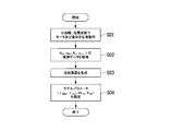
- FIG. 7 is a diagram illustrating a processing flow of the parameter identification device according to the first embodiment.
- FIG. 8 is a diagram for explaining processing of the parameter identification device according to the first embodiment.
- FIGS. 9 to 14 are first to sixth diagrams for explaining a plurality of phase plane views according to the first embodiment.
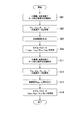
- the processing flow shown in FIG. 7 is executed when the parameter identification device 12 (FIG. 6) performs parameter identification for the mechanical system 2 before starting the actual operation of the mechanical system 2, for example.
- the operator of the motor control system 1 operates the host device to output a predetermined angle command value, thereby repeatedly operating the angle of the load 21 (load angle ⁇ L ) with a small amplitude and a low frequency (step S01). ).
- the data acquisition unit 120 of the parameter identification device 12 determines whether the motor angular velocity ⁇ M , the motor angle ⁇ M , the load angular velocity ⁇ L, and the load angle ⁇ L are elapsed from the mechanical system 2 that is repeatedly operating with a small amplitude and a low frequency.
- the actual measurement data indicating the change is acquired (step S02).
- phase plane diagram generator 121 of the parameter identification device 12 generates a plurality of phase plane diagrams from the actual measurement data acquired in step S02 (step S03).
- the phase plane diagram generation unit 121 measures the torsion angle ( ⁇ M ⁇ L ) acquired before and after the direction inversion of the load angle ⁇ L and the measured data of the torque ⁇ . To link the measured values sampled at the same time.
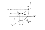
- the “measured data of the twist angle ( ⁇ M ⁇ L )” is obtained by subtracting the measured data of the load angle ⁇ L from the measured data of the motor angle ⁇ M. Then, based on the extracted actual measurement value, the phase plane diagram generation unit 121 is a phase plane diagram with the torsion angle ( ⁇ M ⁇ L ) on the horizontal axis and the torque ⁇ on the vertical axis as shown in FIG.
- a certain “twist angle-torque phase diagram P1” is generated.
- the phase view generating unit 121 the measured data acquired inverted before and after the positive direction of the load angle theta L in the negative direction, the measured data acquired inverted before and after the negative direction to the positive direction, the The actual measurement values are associated with each other.
- a hysteresis curve mainly due to the nonlinear friction characteristic (see FIG. 3A) of the mechanical system 2 and the dead band characteristic function F1 appears.
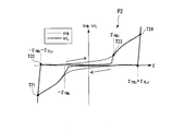
- phase plane view generating unit 121 measured data of the torque ⁇ in the direction reversed before and after the load angle theta L, and the motor angular velocity omega M, Found each other from the measured data of load angular velocity omega L are sampled at the same time And extract them. Then, based on the extracted actual measurement value, the phase plane diagram generation unit 121 is a phase plane diagram with the torque ⁇ on the horizontal axis and the motor angular velocity ⁇ M and the load angular velocity ⁇ L on the vertical axis as shown in FIG. A certain “torque-mechanical angular velocity phase diagram P2” is generated.
- the phase surface diagram generation unit 121 obtains the same time from the measured data of the twist angle ( ⁇ M ⁇ L ) before and after the direction reversal of the load angle ⁇ L and the measured data of the motor angular velocity ⁇ M and the load angular velocity ⁇ L.
- the actual measurement values sampled are linked and extracted.
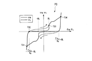
- the phase plane diagram generation unit 121 takes the torsion angle ( ⁇ M ⁇ L ) on the horizontal axis as shown in FIG. 11, and sets the motor angular velocity ⁇ M and the load angular velocity ⁇ L in the vertical direction.
- a “twist angle-mechanical angular velocity phase diagram P3” which is a phase diagram taken on the axis is generated.
- the phase plane diagram generation unit 121 obtains the actual measurement values sampled at the same time from the actual measurement data of the torque ⁇ before and after the direction reversal of the load angle ⁇ L and the actual measurement data of the torsional speed ( ⁇ M ⁇ L ). Link and extract.
- “actual measurement data of torsional speed ( ⁇ M ⁇ L )” is obtained by subtracting the actual measurement data of load angular speed ⁇ L from the actual measurement data of motor angular speed ⁇ M. Then, based on the extracted actual measurement value, the phase plane diagram generator 121 is a phase plane diagram with the torque ⁇ on the horizontal axis and the torsional velocity ( ⁇ M ⁇ L ) on the vertical axis as shown in FIG.
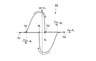
- phase plane diagram generation unit 121 at the same time from the actual measurement data of the twist angle ( ⁇ M ⁇ L ) and the actual measurement data of the twist speed ( ⁇ M ⁇ L ) before and after the direction reversal of the load angle ⁇ L. The sampled measured values are linked and extracted. Then, based on the extracted actual measurement value, the phase plane diagram generator 121 takes the torsion angle ( ⁇ M ⁇ L ) as the horizontal axis and the torsion speed ( ⁇ M ⁇ L ) as shown in FIG. A “twist angle-twist velocity phase diagram P5” which is a phase diagram taken on the axis is generated.
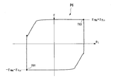
- phase plane view generating unit 121 Furthermore, phase plane view generating unit 121, the measured data of the load angle theta L in the direction reversed before and after the load angle theta L, and extracted in association measured values each other sampled at the same time from the measured data of the torque ⁇ . Then, based on the extracted actual measurement value, the phase plane diagram generation unit 121 is a phase plane diagram that shows the load angle ⁇ L on the horizontal axis and the torque ⁇ on the vertical axis as shown in FIG. A torque phase diagram P6 "is generated.
- the parameter identification unit 122 selects the model motor side friction coefficient ⁇ fM0 , the model load side friction coefficient ⁇ among various model parameters forming the two-inertia system model MOD, based on the various phase diagrams generated in step S03. fL0, to identify the model dead zone width BL 0 and model torsional rigidity coefficient K R0 (step S04). Specifically, the parameter identification unit 122 identifies the model parameter based on the position of a break point in various phase plane views.
- Equation (1), in (2), " ⁇ fM [ ⁇ M]" the motor-side friction which is defined as a variable of the motor angular velocity omega M based on the motor side friction characteristic function G M (in FIG. 3 (b))
- the coefficient ⁇ fM is shown.
- “ ⁇ fL [ ⁇ L] ” represents a load side friction coefficient ⁇ fL defined as a variable of the load angular velocity ⁇ L based on the load side friction characteristic function GL .
- BKLS [ ⁇ M ⁇ L] ” indicates the backlash displacement BKLS defined as a variable of the twist angle ( ⁇ M ⁇ L ) based on the backlash displacement function F1 ′ ((b) of FIG. 4). .
- the torque ⁇ output from the motor 20 according to the torque command value under the condition that the repetitive operation of the mechanical system 2 has a small amplitude and a low frequency is expressed by the motor side friction coefficient ⁇ fM and the load side friction coefficient ⁇ fL . It is shown that it becomes the total value.
- equation (4) under the conditions of repeated operation of the mechanical system 2 is small amplitude and low frequencies, the sum of the value obtained by dividing the backlash displacement BKLS in stiffness coefficient K R torsional load side friction coefficient tau fL twist It is shown that the angle is ( ⁇ M ⁇ L ).
- the value obtained by multiplying the angle (displacement) obtained by subtracting the backlash BKLS from the twist angle ( ⁇ M ⁇ L ) of the shaft 22 by the spring constant (torsional stiffness coefficient K R ) of the shaft 22 is the load side friction coefficient ⁇ . Matches fL .
- the break point T11 to the break point T12 reverse the torque ⁇ , which was saturated in the negative direction, in the positive direction, and the motor 20 rotates in the positive direction accordingly.
- the locus until the start is shown. That is, in a process in which the torque ⁇ that has been the minimum value (saturated in the negative direction) at the break point T11 gradually increases in the positive direction, the saturation value of the friction generated in the motor 20 (motor When the side coulomb friction coefficient ⁇ fMc ) is exceeded, the motor 20 starts to rotate in the positive direction.
- the torque ⁇ at the time when the break point T12 is reached coincides with the saturation value of the friction generated in the motor 20 (motor-side Coulomb friction coefficient ⁇ fMc ) according to the equation (3).
- the bending point T12 to the bending point T13 in the torsion angle-torque phase diagram P1 indicate that the torsion angle ( ⁇ M ⁇ L ) of the shaft 22 reaches the maximum value (+ BL) from the minimum value ( ⁇ BL) of the dead zone. Shows the trajectory. That is, only the backlash BKLS changes from the break point T12 to the break point T13, and no power is transmitted to the load 21. Accordingly, since only the motor 20 is driven, the twist angle ( ⁇ M ⁇ L ) changes while the torque ⁇ is kept constant at the motor side Coulomb friction coefficient ⁇ fMc . Therefore, the twist angle ( ⁇ M ⁇ L ) at the time when the break point T13 is reached coincides with the maximum value (+ BL) of the dead zone from the equation (4).
- the break point T13 to the break point T14 in the twist angle-torque phase diagram P1 are applied to the load 21 through the twist angle ( ⁇ M ⁇ L ) where the backlash displacement BKLS is saturated in the positive direction and exceeds the dead band width BL.
- the locus until the applied torque ⁇ ′ gradually increases and the load 21 starts to rotate in the positive direction according to this is shown. That is, in the process in which the torque ⁇ , which has been driving only the motor 20 at the break point T13, further increases in the positive direction, the torque ⁇ becomes the saturation value of the friction generated in the motor 20 and the friction generated in the load 21.
- the load 21 starts to rotate in the positive direction when it is balanced with the total value of the saturation value (the load side coulomb friction coefficient ⁇ fLc ). Therefore, the torque ⁇ at the time when the break point T14 is reached coincides with the total value of the motor-side coulomb friction coefficient ⁇ fMc and the load-side coulomb friction coefficient ⁇ fLc from the equation (3). Further, the twist angle ( ⁇ M ⁇ L ) at the time when the break point T14 is reached coincides with “ ⁇ fLc / K R + BL” from the equation (4).
- the parameter identification unit 122 identifies various model parameters based on the positions of the break points T11 to T14. Specifically, the parameter identification unit 122 identifies the model motor side Coulomb friction coefficient ⁇ fMc0 with reference to the value of the vertical axis of the break point T12 (or the break point T13) in the twist angle-torque phase diagram P1. In addition, the parameter identification unit 122 identifies the model load side Coulomb friction coefficient ⁇ fLc0 by subtracting the value of the previously identified model motor side Coulomb friction coefficient ⁇ fMc0 from the value of the vertical axis at the break point T14.
- the parameter identification unit 122 identifies the model dead zone width BL 0 with reference to the value on the horizontal axis of the break point T13 (or break point T12). Further, the parameter identification unit 122, by solving the value on the horizontal axis at the break point T14, the equation (4) based on the model dead zone width BL 0 and model load side Coulomb friction coefficient tau FLC0 previously identified, the model The torsional stiffness coefficient K R0 is identified.
- the break points T21 to T24 in the torque-mechanical angular velocity phase diagram P2 shown in FIG. 10 will be described with consideration given to the relationship between the expressions (3) and (4).
- the torque ⁇ saturated in the negative direction is reversed toward the positive direction, and accordingly, the torque ⁇ is the minimum value (negative saturation).
- the trajectory until the angular velocity of the motor 20 and the load 21 becomes zero is shown with almost no change from the state.
- the break points T22 to T23 are caused by the presence of the dead zone ( ⁇ BL to + BL) due to the presence of the dead zone ( ⁇ BL to + BL) while the torque ⁇ gradually increases in the positive direction from the state where the angular velocity of the motor 20 and the load 21 is zero. shows the trajectory only angular velocity ⁇ M is increased. Further, at the break points T23 to T24, the torque ⁇ exceeds the torque required for driving only the motor 20 (motor-side Coulomb friction coefficient ⁇ fMc ), so that the torque ⁇ ′ is applied to the load 21 and the motor angular velocity ⁇ M And the load angular velocity ⁇ L are shown to rise equally.
- the value on the horizontal axis of the break point T22 can be obtained as “ ⁇ fMc ⁇ fLc ” from Equation (3) based on the fact that the motor angular velocity ⁇ M and the load angular velocity ⁇ L are zero.
- the value on the horizontal axis of the break point T23 is the torque at the time when the angular velocity of the load 21 starts to rise (when only the motor 20 is rotationally driven). Therefore, from equation (3), the value on the horizontal axis of the break point T23 matches the motor-side Coulomb friction coefficient ⁇ fMc .
- the parameter identification unit 122 subtracts the value of the previously identified model motor side Coulomb friction coefficient ⁇ fMc0 from the value of the horizontal axis of the break point T22 in the torque-mechanical angular velocity phase diagram P2 to obtain the model load side Coulomb friction coefficient ⁇ fLc0. Is identified.
- the break point T22 have not undergone the motor angular speed omega M, the influence of the motor side viscosity gives a component proportional to the load angular velocity omega L D M and the load side viscosity coefficient D L. Therefore, the model load side Coulomb friction coefficient ⁇ fLc0 with higher accuracy can be identified from the value on the horizontal axis of the break point T22.
- the parameter identifying unit 122 identifies the model motor side Coulomb friction coefficient ⁇ fMc0 with reference to the value of the horizontal axis of the break point T23 in the torque-mechanical angular velocity phase diagram P2.
- Torsion angle-mechanical angular velocity phase plane P3 shows that the torque ⁇ saturated in the negative direction is reversed in the positive direction and the twist angle ( ⁇ M ⁇ L ) Shows a trajectory until the angular velocity of the motor 20 and the load 21 becomes zero while hardly changing from the minimum value (negative saturated state).
- the bending point T32 to the bending point T33 have a twist angle ( ⁇ M ⁇ L ) because only the motor angular velocity ⁇ M increases with the load angular velocity ⁇ L being zero due to the presence of the dead zone ( ⁇ BL to + BL). It shows a trajectory that gradually increases. Further, at the break point T33 to the break point T34, the torque ⁇ ′ is applied to the load 21 when the twist angle ( ⁇ M ⁇ L ) exceeds the maximum value (+ BL) of the dead zone, and the motor angular speed ⁇ M and the load angular speed ⁇ A locus in which L rises equally is shown.
- the value on the horizontal axis of the break point T32 is based on the fact that the load angular velocity ⁇ L is zero and the backlash displacement BKLS is “ ⁇ BL” ( ⁇ M ⁇ L ⁇ BL). From (4), it can be obtained as “ ⁇ fLc / K R -BL”.
- the value on the horizontal axis of the break point T33 is the twist angle ( ⁇ M ⁇ L ) at the time when the angular velocity of the load 21 starts to rise (when the load angular velocity ⁇ L is zero). Therefore, the value on the horizontal axis of the break point T33 coincides with the maximum value (+ BL) of the dead zone from the equation (4).
- Parameter identification unit 122 twist angle - based on the mechanical angular value of the horizontal axis of the broken point T32 in the phase plane diagram P3, model dead zone width BL 0 and model load side Coulomb friction coefficient tau FLC0 above-identified formula ( By solving 4), the model torsional stiffness coefficient K R0 is identified.
- a torque-torsion speed phase diagram P4 shown in FIG. 12 is a phase diagram showing a difference between the motor angular velocity ⁇ M and the load angular velocity ⁇ L shown in the torque-mechanical angular velocity phase diagram P2 (FIG. 10). Therefore, the position of the break point T41 in the torque-torsion speed phase diagram P4 corresponds to the position of the break point T21 in the torque-mechanical angular velocity phase diagram P2. Further, the position of the break point T42 in the torque-torsion speed phase diagram P4 corresponds to the position of the break point T23 in the torque-mechanical angular velocity phase diagram P2. Further, the position of the break point T43 in the torque-torsion speed phase diagram P4 corresponds to the position of the break point T24 in the torque-mechanical angular velocity phase diagram P2.
- the parameter identification unit 122 identifies the model motor side Coulomb friction coefficient ⁇ fMc0 with reference to the value on the horizontal axis of the break point T42 in the torque-torsion speed phase diagram P4.
- the break point T42 in the torque-torsion speed phase diagram P4 is more clearly shown than the break point T23 in the torque-mechanical angular velocity phase diagram P2 (FIG. 10). Therefore, the model motor side Coulomb friction coefficient ⁇ fMc0 can be identified with higher accuracy.
- the twist angle-torsion speed phase diagram P5 shown in FIG. 13 is a phase diagram showing the difference between the motor angular velocity ⁇ M and the load angular velocity ⁇ L shown in the twist angle-mechanical angular velocity phase diagram P3 (FIG. 11). . Therefore, the position of the break point T51 in the twist angle-twist velocity phase plane diagram P5 corresponds to the position of the break point T31 in the twist angle-mechanical angular velocity phase diagram P3.
- the position of the break point T52 in the twist angle-torsion speed phase diagram P5 corresponds to the position of the break point T32 in the twist angle-mechanical angular velocity phase diagram P3. Further, the position of the break point T53 in the twist angle-torsion speed phase diagram P5 corresponds to the position of the break point T33 in the twist angle-mechanical angular velocity phase diagram P3. Further, the position of the break point T54 in the twist angle-twist velocity phase diagram P5 corresponds to the position of the break point T34 in the twist angle-mechanical angular velocity phase diagram P3.
- the parameter identification unit 122 identifies the model dead zone width BL 0 with reference to the value on the horizontal axis of the break point T53 in the twist angle-twist speed phase diagram P5.
- the parameter identification unit 122 twist angle - the value of the horizontal axis of the twisted rate phase plane view P5 break point T52 at, based on the model dead zone width BL 0 and model load side Coulomb friction coefficient tau FLC0 previously identified
- the model torsional stiffness coefficient K R0 is identified.
- the break point T52 and the break point T53 in the twist angle-torsion speed phase diagram P5 are clearer than the break points T32, T33 in the twist angle-mechanical angular velocity phase diagram P3 (FIG. 11). Is shown in Therefore, the model dead zone width BL 0 and the model torsional stiffness coefficient K R0 can be identified with higher accuracy.
- break points T61 and T63 derived from the load angle-torque phase diagram P6 shown in FIG. 14 will be described.
- both the motor-side friction coefficient ⁇ fM and the load-side friction coefficient ⁇ fL are saturated. Therefore, the equation (3), the value of the vertical axis of the break point T61, "- ⁇ fMc - ⁇ fLc ", the value of the vertical axis of the break point T63 can be obtained as " ⁇ fMc + ⁇ fLc".
- the parameter identification unit 122 subtracts the value of the previously identified model motor side Coulomb friction coefficient ⁇ fMc0 from the value of the vertical axis of the break point T63 in the load angle-torque phase diagram P6 to obtain the model load side Coulomb friction coefficient ⁇ fLc0. Is identified.
- the break point T63 in the load angle-torque phase diagram P6 is more clearly shown than the break point T14 in the twist angle-torque phase diagram P1 (FIG. 9). Therefore, the model load side Coulomb friction coefficient ⁇ fLc0 can be identified with higher accuracy.
- the parameter identification unit 122 for example, from the model motor side friction coefficient ⁇ fM0 identified from the break point T42 of the torque-torsion speed phase diagram P4, from the break point T22 of the torque-mechanical angular velocity phase diagram P2.
- the identified model load side friction coefficient ⁇ fL0 is adopted.
- the parameter identification unit 122 is, for example, twist angle - to adopt a twist rate of each model were identified from the dead zone width of break points T52 and break point T53 of the phase plane diagram P5 BL 0 and model torsional rigidity coefficient K R0. Thereby, any model parameter can be identified with high accuracy.
- the parameter identification unit 122 substitutes the model motor side Coulomb friction coefficient tau FMc0 identified on the motor side friction characteristic function G M (see (b) of FIG. 3).
- the parameter identification unit 122 by multiplying a predetermined coefficient to model motor side Coulomb friction coefficient tau FMc0, various constants (slope K 1 constituting the motor side friction characteristic function G M, K 2, K 3 , K 4 , offsets ⁇ fM1 , ⁇ fM2 , ⁇ fM3 , ⁇ fM4 , ⁇ fM5 ).
- the parameter identification part 122 identifies model motor side friction coefficient (tau) fM0 .
- the parameter identification unit 122 substitutes the identified model load side Coulomb friction coefficient ⁇ fLc0 for the addition side friction characteristic function GL . Then, the parameter identification unit 122 identifies various constants (inclination and offset) constituting the load side friction characteristic function GL by multiplying the model load side Coulomb friction coefficient ⁇ fLc0 by a predetermined coefficient. Thereby, the parameter identification part 122 identifies model load side friction coefficient (tau) fL0 .
- the parameter identification unit 122 performs PSO (Particle Swarm Optimization) or the like on the generated various phase front views, and the error area with the hysteresis curve shown in each front view is minimized. Each broken point is detected by performing such a broken line approximation calculation.
- PSO particle Swarm Optimization
- the parameter identification device 12 is configured to include the above-described data acquisition unit 120, the phase plane diagram generation unit 121, and the parameter identification unit 122.
- the motor-side friction coefficient ⁇ fM , the load-side friction coefficient ⁇ fL , the dead band width BL, and the torsional rigidity coefficient K R of the mechanical system 2 are determined from a plurality of break points and the like shown in the plurality of phase planes. Can be evaluated independently and model parameters corresponding to the various parameters can be accurately identified. Therefore, it is possible to obtain a two-inertia model MOD that accurately simulates the mechanical system 2 having the motor 20 and the load 21.
- phase plane diagram generation unit 121 shows, as a phase plane diagram, a torque-torsion velocity phase diagram P4 showing the relationship between the torque ⁇ and the torsional velocity ( ⁇ M ⁇ L ) of the shaft 22. Is generated. Then, the parameter identification unit 122 identifies a model parameter (model motor side friction coefficient ⁇ fM0 ) indicating the friction of the motor 20 based on the position of the break point in the torque-torsion speed phase diagram P4. In this way, the model motor side friction coefficient ⁇ fM0 can be identified with higher accuracy.
- model parameter model motor side friction coefficient ⁇ fM0
- the phase plane diagram generation unit 121 has a relationship between the twist angle ( ⁇ M ⁇ L ) of the shaft 22 and the twist speed ( ⁇ M ⁇ L ) of the shaft 22 as a phase plane diagram.
- a torsion angle-torsion speed phase diagram P5 is generated.
- the parameter identification unit 122 models parameters indicating the rigidity of the shaft 22 and the dead band width (model torsional stiffness coefficient K R0 , model dead band width BL based on the position of the break point in the twist angle-twist velocity phase diagram P5. 0 ) is identified. By doing so, the model torsional stiffness coefficient K R0 and the model dead zone width BL 0 can be identified with higher accuracy.
- phase surface diagram generation unit 121 generates a torque-mechanical angular velocity phase diagram P2 indicating the relationship between the torque ⁇ and the angular velocity of the motor 20 or the angular velocity of the load 21 as a phase surface diagram. .
- the parameter identification unit 122 identifies a model parameter (model load side friction coefficient ⁇ fL0 ) indicating the friction of the load 21 based on the position of the break point in the torque-mechanical angular velocity phase diagram P2. In this way, the model load side friction coefficient ⁇ fL0 can be identified with higher accuracy.
- the phase plane diagram generating unit 121 generates a load angle-torque phase plane diagram P6 indicating the relationship between the angle of the load 21 (load angle ⁇ L ) and the torque ⁇ as the phase plane diagram. To do. Then, the parameter identification unit 122 identifies a model parameter (model load side friction coefficient ⁇ fL0 ) indicating the friction of the load 21 based on the position of the break point in the load angle-torque phase diagram P6. In this way, the model load side friction coefficient ⁇ fL0 can be identified with higher accuracy.
- the phase plane diagram generating unit 121 has a twist angle-torque phase plane diagram P1 showing the relationship between the twist angle ( ⁇ M ⁇ L ) of the shaft 22 and the torque ⁇ as a phase plane diagram. Is generated. Then, the parameter identification unit 122 selects the friction of the motor 20, the friction of the load 21, the rigidity of the shaft 22 and the dead band width of the shaft 22 based on the position of the break point in the twist angle-torque phase diagram P1. A model parameter indicating at least one of them is identified. In this way, the model motor side friction coefficient ⁇ fM0 , the model load side friction coefficient ⁇ fL0 , the model torsional rigidity coefficient K R0, and the model dead zone width BL 0 can be identified from one phase plane.
- the parameter identification unit 122 calculates an average value thereof. It may be a model parameter.
- the parameter identification unit 122 calculates an average value of the model dead zone width BL 0 identified from the torsion angle-torque phase diagram P1 and the model dead zone width BL 0 identified from the torsion angle-torsion velocity phase diagram P5. May be used as the model dead zone width BL 0 adopted in the two-inertia model MOD.
- phase plane diagram generating unit 121 may generate only one phase plane diagram (twist angle-torque phase plane diagram P1).
- the parameter identification unit 122 calculates the model motor side friction coefficient ⁇ fM0 , the model load side friction coefficient ⁇ fL0 , the model torsional rigidity coefficient K R0, and the model dead zone width BL 0 from the generated twist angle-torque phase diagram P1. Identify everything. By doing in this way, the identification process of each model parameter can be simplified.
- phase plane diagram generation unit 121 repeats acquisition of actual measurement data for each repetitive operation of the mechanical system 2 and generates each phase plane diagram based on the averaged result. Also good. By doing so, the variation error of the measured data is reduced, so that the identification accuracy of the model parameters can be further increased.
- parameter identification device 12 can be used not only for the feedforward function in the motor control system 1 but also for abnormality diagnosis and machine adjustment of the motor control system 1.
- the parameter identification device 12 has been described as performing the above-described various processes with the torque command value input from the host device as “torque ⁇ ”. It is not limited to an aspect.
- the parameter identification device 12 according to another embodiment performs the above-described various processes by using not “torque command value” but “measured torque” obtained from the detected current value flowing through the motor 20 as “torque ⁇ ”. An aspect may be sufficient.
- the parameter identification device 12 When there is a steady disturbance such as gravity, a constant offset is applied to the torque ⁇ and the twist angle ( ⁇ M ⁇ L ). Therefore, the parameter identification device 12 according to another embodiment further has a function of calculating the average of the torque ⁇ and the torsion angle ( ⁇ M ⁇ L ) to remove the offset, and a function of averaging the break points positively and negatively. You may have.
- FIG. 15 is a diagram illustrating a functional configuration of the parameter identification device according to the second embodiment.
- the parameter identification device 12 according to the second embodiment further includes a motor side error system 123 and a load side error system 124.
- the motor-side error system 123 is based on the torque ⁇ , the motor angle ⁇ M , and the load angle ⁇ L calculated by the feedback control unit 10 and the feed-forward control unit 11, and is a motor-side model of the two inertia system model MOD.
- the motor side error signal e M indicating the degree of error with respect to the motor 20 is output.
- the load-side error system 124 generates a load-side error signal e L indicating the degree of error of the load-side model of the two-inertia system model MOD with respect to the load 21 based on the motor angle ⁇ M and the load angle ⁇ L. Output.
- the parameter identification unit 122 receives the motor-side error signal e M and inputs a model parameter group (J M0 , D M0 , ⁇ fM0 , etc.) that forms a motor-side model of the two-inertia system model MOD. BL 0 ) is identified.
- the parameter identification unit 122 receives the load-side error signal e L and identifies model parameters (J L0 , D L0 , ⁇ fL0 , BL 0 ) that form a load-side model among the two inertial system models MOD. .
- FIG. 16 is a first diagram illustrating processing of the motor side error system and the load side error system according to the second embodiment.
- the motor side error system 123 receives the torque ⁇ , the motor angle ⁇ M, and the load angle ⁇ L , and calculates the motor side error signal e M according to the block diagram shown in FIG.
- each of the model parameter groups (J M0 , D M0 , ⁇ fM0 , BL 0 ) forming the motor side model is an unknown parameter group (J M , D M , ⁇ fM ) indicating the actual characteristics of the motor 20.
- the position of the motor 20 rotated by the torque ⁇ calculated based on the model parameter group (motor angle ⁇ M ) is the assumed position of the motor 20. It should deviate from (target motor angle). Therefore, the degree of error between the torque that should have been originally applied to the motor 20 to reach the assumed target motor angle and the torque ⁇ actually applied to the motor 20 is represented by the motor-side error signal e M.
- the equation shown in equation (5) is established from the input / output relationship of the portion related to the motor 20.
- the motor side error system 123 calculates the motor side error signal e M based on the equation (5).
- a portion corresponding to the motor-side error system 123 is a block diagram corresponding to a modified expression of Expression (5).
- the motor-side error system 123 receives the input torque ⁇ and motor angle ⁇ M. and calculates the motor-side error signal e M based on the load angle theta L.
- sign (s ⁇ M ) (sign function S1 shown in FIG. 16) takes a value of “+1” when s ⁇ M is positive (s ⁇ M > 0), and s ⁇ M is negative (s ⁇ M ⁇ 0).
- BKLS ( ⁇ M ⁇ L ) (dead zone characteristic function F1 shown in FIG. 16) is a system (a model simulating the shaft 22) in which power is transmitted from the motor side to the load side in the two inertia system model MOD. properties is a non-linear function expressed by the model dead zone width BL 0 to.
- the model dead zone width BL 0 is a value that defines the “play” width (dead zone width BL) as a model, and the dead zone characteristic function F1 has an absolute value of the deviation ( ⁇ M ⁇ L ) as the model dead zone width BL 0.
- the load side error system 124 receives the motor angle ⁇ M and the load angle ⁇ L , and calculates the load side error signal e L according to the block diagram shown in FIG.
- each of the model parameter groups (J L0 , D L0 , ⁇ fL0 , BL 0 ) forming the load side model is a parameter group (J L , D L , ⁇ fL , BL) indicating the actual characteristics of the load 21. )
- the load angle (load angle ⁇ L ) rotated by the torque ⁇ calculated based on the model parameter group is the assumed load angle (target angle ⁇ t ). Deviate.
- Load error system 124 calculates the motor-side error signal e M based on the equation (6).
- a portion corresponding to the load-side error system 124 is a block diagram corresponding to a modified expression of Expression (6).
- the load-side error system 124 includes the input motor angle ⁇ M and the load angle in accordance with the block diagram shown in FIG. 16 and model parameters (J L0 , D L0 , ⁇ fL0 , BL 0 ) given in advance. calculating a load-side error signal e L based on the theta L.
- sign (s ⁇ L ) (sign function S2 shown in FIG. 16) takes a value of “+1” when s ⁇ L is positive (s ⁇ L > 0), and s ⁇ L is negative (s ⁇ L ⁇ 0). Is a nonlinear function that takes a value of “ ⁇ 1”.
- FIG. 17 is a second diagram illustrating processing of the motor-side error system and the load-side error system according to the second embodiment.
- each of the model parameter groups (J M0 , D M0 , ⁇ fM0 , J L0 , D L0 , ⁇ fL0 , BL 0 ) and parameter groups (J M , D M , ⁇ fM , J L , D L , ⁇ fL , BL) are respectively expressed as motor side moment of inertia error component ⁇ J M , motor side viscosity coefficient error component ⁇ D M , motor side friction coefficient error, respectively.
- the motor side error signal e M and the load side error signal e L calculated based on the block diagram shown in FIG. 16 are converted into the error component parameter group ( ⁇ J M , ⁇ D M, ⁇ fM, ⁇ J L , ⁇ D L, ⁇ fL, can be represented by [Delta] BL).
- the motor-side error signal e M is an error corresponding to each of a plurality of model parameter groups (J M0 , D M0 , ⁇ fM0 , BL 0 ) forming a motor-side model among the two inertial system models MOD.
- the component motor side error parameter group ( ⁇ J M, ⁇ D M, ⁇ fM, ⁇ BL) based on, can be expressed as equation (8).
- the load side error signal e L is an error component corresponding to each of a plurality of model parameter groups (J L0 , D L0 , ⁇ fL0 , BL 0 ) forming a load side model of the two inertial system model MOD.
- load error parameter group ( ⁇ J L, ⁇ D L, ⁇ fL, ⁇ BL) based on it can be expressed by equation (9).
- the dead zone width error component ⁇ BL an error component corresponding to the model parameter indicating the dead zone width BL (model dead zone width BL 0), i.e., the model dead zone width BL 0 is defined as 2-inertia system model MOD and mechanical 2 Is an error from the actual dead band width BL.
- ⁇ BKLS ( ⁇ M ⁇ L ) / ⁇ BL dead band characteristic change function F2 shown in FIG. 17) is a non-linear representing the degree of change that the dead band width error component ⁇ BL gives to the characteristic of the dead band characteristic function F1 described above. It is a function. Details of the dead zone characteristic change function F2 will be described later.
- the motor-side error system 123 includes a motor-side internal signal q that linearly associates each of the motor-side error parameter groups ( ⁇ J M , ⁇ D M , ⁇ fM , ⁇ BL) with the motor-side error signal e M. 0M , q 1M , q 2M and dead band internal signal q 3 are output.
- the load-side error system 124 includes a load-side error parameter group ( ⁇ J L , ⁇ D L , ⁇ fL , ⁇ BL) and a load-side error signal e L that is linearly associated with each other.
- the internal signals q 0L , q 1L , q 2L and the dead zone internal signal q 3 are output.
- the dead zone internal signal q 3 dead zone of the dead zone for the internal signal q 3 and the load-side error system 124 outputs the motor-side error system 123 outputs is identical, for convenience of explanation, the motor-side error system 123 outputs
- the internal signal q 3 for use is also referred to as a motor side internal signal q 3
- the dead zone internal signal q 3 output from the load side error system 124 is also referred to as a load side internal signal q 3 .
- motor-side internal signals q 0M , q 1M , q 2M , and q 3 are respectively expressed by equations (Motor angle ⁇ M , load angle ⁇ L) and the block diagram shown in FIG. 10).
- Each of the motor-side internal signals q 0M , q 1M , q 2M , and q 3 calculated in this way includes a motor-side error parameter group ( ⁇ J M , ⁇ D M , ⁇ fM , ⁇ BL) and a motor-side error. a parameter correlating the signal e M, the linear.
- load-side internal signals q 0L , q 1L , q 2L , and q 3 are respectively expressed by equations (11) based on the input motor angle ⁇ M , load angle ⁇ L , and the block diagram shown in FIG. ).
- Each of the load side internal signals q 0L , q 1L , q 2L , and q 3 calculated in this way includes a load side error parameter group ( ⁇ J L , ⁇ D L , ⁇ fL , ⁇ BL) and a load side error. a parameter correlating the signal e L, the linear.
- FIG. 18 is a third diagram for explaining processing of the motor-side error system and the load-side error system according to the second embodiment.
- the motor-side error system 123 and the load-side error system 124 according to the present embodiment output a dead zone internal signal q 3 as shown in FIG.
- a characteristic change function F2 is used.
- the dead band characteristic change function F2 indicates the degree of change that the dead band width error component ⁇ BL gives to the transmission characteristic of the system in which power is transmitted from the motor 20 side to the load 21 side (characteristic of the dead band characteristic function F1). This is a non-linear function to be defined.
- the “play” width (dead band width BL) of the shaft 22 provided between the motor 20 and the load 21 changes from the model dead band width BL 0 by a predetermined dead band width error component ⁇ BL ( ⁇ BL> 0).
- ⁇ BL dead band width error component
- the dead band characteristic function F1 when the dead band width BL is BL 0 , the output increases when the input ( ⁇ M ⁇ L ) exceeds BL 0 , whereas the dead band width BL is ( When changes to BL 0 + ⁇ BL), until the input ( ⁇ M - ⁇ L) is greater than (BL 0 + ⁇ BL), the output remains "zero". Therefore, when the input ( ⁇ M ⁇ L ) is in the range from BL 0 to (BL 0 + ⁇ BL), the input ( ⁇ M ⁇ L ) and the degree of change of the output in the negative direction are in a proportional relationship. is there.
- the input ( ⁇ M ⁇ L ) when the input ( ⁇ M ⁇ L ) is in the range from ⁇ BL 0 to ( ⁇ BL 0 ⁇ BL), the input ( ⁇ M ⁇ L ) and the degree of change in the positive direction of the output, Are in a proportional relationship.
- the output In the region where the input ( ⁇ M ⁇ L ) is from BL 0 to ⁇ BL 0 , the output remains “zero” regardless of the change in the dead band width BL from BL 0 to (BL 0 + ⁇ BL). . That is, even if the dead band width BL changes from BL 0 to (BL 0 + ⁇ BL), the output does not change.
- the dead band characteristic change function F2 representing the degree of change that the dead band width error component ⁇ BL gives to the characteristic of the dead band characteristic function F1 can be expressed by a nonlinear characteristic as shown in FIG. That is, in the region where the input ( ⁇ M ⁇ L ) exceeds BL 0 + ⁇ BL ′, the output by the dead band characteristic function F1 changes in the negative direction, so the dead band characteristic change function F2 outputs “ ⁇ 1”. Similarly, in the region where the input ( ⁇ M ⁇ L ) is lower than ⁇ BL 0 ⁇ BL ′, the output by the dead band characteristic function F1 changes in the positive direction, so the dead band characteristic change function F2 outputs “+1”. To do.
- the output is changed from “zero” to “ ⁇ 1” as the input ( ⁇ M ⁇ L ) increases. Until it gradually decreases.
- the output starts from “zero” as the input ( ⁇ M ⁇ L ) decreases. It changes to gradually increase to “+1”.
- the output of the dead band characteristic function F1 does not change, so the dead band characteristic change function F2 outputs “zero”.
- the constant ⁇ BL ′ is a constant determined by predicting the assumed deadband error component ⁇ BL in advance.
- the parameter identification unit 122 uses the motor-side error signal e M (see FIG. 16) calculated by the motor-side error system 123 and the motor-side internal signals q 0M , q 1M , q 2M calculated by the motor-side error system 123. , Q 3 (see FIG. 17).
- the parameter identification unit 122 is configured so that each of the motor-side internal signals q 0M , q 1M , q 2M , and q 3 includes an unknown motor-side error parameter group ( ⁇ J M , ⁇ D M , ⁇ fM , ⁇ BL) Each of the unknown motor-side error parameter groups is calculated using the fact that the error signal e M is linearly related as shown in Expression (12).
- the parameter identification unit 122 acquires the motor-side error signal e M corresponding to one cycle T of the periodic operations in the mechanical system 2 and the motor-side internal signals q 0M , q 1M , q 2M , and q 3 . Then, multiplying both sides of the equation (12) by the motor side internal signals q 0M , q 1M , q 2M , q 3 , and further integrating both sides by one period T, the shape is transformed as in the equation (13). .
- equation (13) is transformed into equation (14).
- the parameter identification unit 122 can calculate an unknown motor-side error parameter group ( ⁇ J M , ⁇ D M , ⁇ fM , ⁇ BL) according to the equation (15).
- Parameter identification unit 122 the calculated motor side error parameter group ( ⁇ J M, ⁇ D M, ⁇ fM, ⁇ BL) each, the model parameter groups constituting the motor side of the model (J M0, D M0, ⁇ fM0, BL 0 )), a new model parameter group (J M0 , D M0 , ⁇ fM0 , BL 0 ) is identified.
- the parameter identification unit 122 uses the motor-side error signal e L (see FIG. 16) calculated by the load-side error system 124 and the load-side internal signals q 0L , q 1L , which are also calculated by the load-side error system 124. q 2L and q 3 (see FIG. 17).
- the parameter identification unit 122 is configured such that each of the load-side internal signals q 0L , q 1L , q 2L , q 3 includes an unknown load-side error parameter group ( ⁇ J L , ⁇ D L , ⁇ fL , ⁇ BL) Each of the unknown load-side error parameter groups is calculated using the fact that the error signal e L is linearly related as shown in Expression (16).
- the parameter identification unit 122 acquires the load-side error signal e L corresponding to one cycle T of the periodic operations in the mechanical system 2 and the load-side internal signals q 0L , q 1L , q 2L , q 3 . Then, by multiplying both sides of the equation (16) by the load side internal signals q 0L , q 1L , q 2L , q 3 , and further integrating both sides by one period T, the equation is transformed as shown in the equation (17). .
- equation (17) is transformed into equation (18).
- the parameter identification unit 122 can calculate an unknown load-side error parameter group ( ⁇ J L , ⁇ D L , ⁇ fL , ⁇ BL) according to the equation (19).
- Parameter identification unit 122 the calculated load error parameter group ( ⁇ J L, ⁇ D L, ⁇ fL, ⁇ BL) respectively, the model parameter groups that form a model of predefined have load side (J L0, D L0 , tau fL0, BL 0) is subtracted from each of identifying new model parameter group (J L0, D L0, ⁇ fL0, BL 0).
- the parameter identification unit 122 includes the motor-side error signal e M and the load-side error signal e L for one cycle T of the periodic operations in the mechanical system 2, and various types for the same one cycle T.
- Internal signals q 0M , q 1M , q 2M , q 0L , q 1L , q 2L , q 3 are acquired, and relational expressions (Equation (12), Equation (16)) between the error signal and the error parameter group are obtained. Time integration is performed in one cycle T.
- FIG. 19 is a diagram showing a processing flow of the parameter identification device according to the second embodiment.
- the processing flow shown in FIG. 19 is the same as that of the first embodiment (FIG. 7), for example, before the start of the actual operation of the mechanical system 2, the parameter identification device 12 (FIG. 15) sets the parameters for the mechanical system 2. It is executed when identification is performed.
- the parameter identification device 12 performs a model motor on the basis of various measured data ( ⁇ M , ⁇ M , ⁇ L , ⁇ L , ⁇ ) acquired during repetitive operation with a small amplitude and low frequency through steps S01 to S04.
- the side friction coefficient ⁇ fM0 , the model load side friction coefficient ⁇ fL0 , the model dead zone width BL 0 , and the model torsional rigidity coefficient K R0 are identified. Since the processes in steps S01 to S04 shown in FIG. 19 are the same as those in the first embodiment (FIG. 7), the description thereof is omitted.
- the operator of the motor control system 1 operates the host device to output a predetermined angle command value, thereby repeatedly operating the angle of the load 21 (load angle ⁇ L ) with a large amplitude and a high frequency (step) S11).
- the data acquisition unit 120 of the parameter identification device 12 determines the time lapse of the motor angular velocity ⁇ M , the motor angle ⁇ M , the load angular velocity ⁇ L, and the load angle ⁇ L from the mechanical system 2 that is repeatedly operating with large amplitude and high frequency. Actual measurement data indicating a change is acquired (step S12).
- the motor-side error system 123 of the parameter identification device 12 is subjected to the processing described with reference to FIGS. 16 to 18, and the motor-side error signal e M and the motor-side internal signals q 0M , q 1M , q 2M and the dead band. and it outputs an internal signal q 3.
- the load side error system 124 of the parameter identification device 12 is subjected to the processing described with reference to FIGS. 16 to 18 and the load side error signal e L , the load side internal signals q 0L , q 1L , q 2L and the dead zone internals. and it outputs a signal q 3 (step S13).
- the parameter identification unit 122 sets a motor side error parameter group ( ⁇ J M , ⁇ D M , ⁇ fM , ⁇ BL) based on various error signals and internal signals input from the motor side error system 123 and the load side error system 124. And a load side error parameter group ( ⁇ J L , ⁇ D L , ⁇ fL , ⁇ BL) are calculated. Then, the parameter identification unit 122 identifies the remaining model parameters that have not been identified in step S04 based on these error parameter groups (step S14).
- the parameter identification unit 122 identifies the model motor side moment of inertia J M0 , the model motor side viscosity coefficient D M0 , the model load side moment of inertia J L0 , and the model load side viscosity coefficient D L0 . To do.
- the parameter identification device 12 includes the first step of performing identification when the amplitude and frequency of the repetitive motion performed by the mechanical system 2 are relatively small and low, and the machine The model parameters are identified separately in the second step of performing identification when the amplitude and frequency of the repetitive motion performed by the system 2 are relatively large and high. More specifically, the parameter identification unit 122 determines the motor based on the torque ⁇ acquired in the first step, the measured data of the angle and angular velocity of the motor 20, and the measured data of the angle and angular velocity of the load 21. Model parameters indicating friction, load friction, shaft 22 stiffness, and shaft 22 deadband width are identified.
- the parameter identification unit 122 calculates the moment of inertia and the viscosity coefficient of the motor 20 based on the torque ⁇ acquired in the second step, the measured data of the angle of the motor 20, and the measured data of the angle of the load 21.
- Model parameters model motor side moment of inertia J M0 , model motor side viscosity coefficient D M0
- model parameters model load side moment of inertia J L0
- a program for realizing the function of the parameter identification device 12 in the motor control system 1 is recorded on a computer-readable recording medium, and the program recorded on the recording medium is stored in the computer system. It is assumed that each procedure is performed by loading and executing.
- each process of the parameter identification device 12 described above is stored in a computer-readable recording medium in the form of a program, and the above-described various processes are performed by the computer reading and executing the program.
- the computer-readable recording medium means a magnetic disk, a magneto-optical disk, a CD-ROM, a DVD-ROM, a semiconductor memory, or the like.
- the computer program may be distributed to the computer via a communication line, and the computer that has received the distribution may execute the program.
- the aspect with which the function of the parameter identification apparatus 12 is comprised over the some apparatus connected with a network may be sufficient.
Landscapes
- Engineering & Computer Science (AREA)
- Physics & Mathematics (AREA)
- General Physics & Mathematics (AREA)
- Automation & Control Theory (AREA)
- Power Engineering (AREA)
- Human Computer Interaction (AREA)
- Manufacturing & Machinery (AREA)
- Testing And Monitoring For Control Systems (AREA)
- Numerical Control (AREA)
- Feedback Control In General (AREA)
- Control Of Ac Motors In General (AREA)
- Control Of Electric Motors In General (AREA)
Abstract
パラメータ同定装置(12)は、モータに対するトルクτと、モータの角度θ(M)及び角速度ω(M)の実測データと、負荷の角度θ(L)及び角速度ω(L)の実測データと、を取得するデータ取得部(120)と、取得された各種実測データに基づいて複数の位相面図を生成する位相面図生成部(121)と、生成された複数の位相面図に基づいて、モータの摩擦、負荷の摩擦、連結部材の剛性、及び、連結部材の不感帯幅を示すモデルパラメータ(τ(fM0)、τ(fL0)、(BL0)、(KR0))を同定するパラメータ同定部と、を備える。
Description
本発明は、パラメータ同定装置、モータ制御システム、パラメータ同定方法及びプログラムに関する。
本願は、2016年5月25日に日本に出願された特願2016-104481号について優先権を主張し、その内容をここに援用する。
本願は、2016年5月25日に日本に出願された特願2016-104481号について優先権を主張し、その内容をここに援用する。
負荷を駆動させるモータの制御系(モータ制御システム)の設計において制御性能を向上させるためにはフィードバック制御では限界があり、指令信号に対する応答特性が高いフィードフォワード制御を行う必要がある。また、フィードフォワード制御を実現するためには、制御システム側が、制御対象(即ち、モータ及び負荷を有する機械系)を模したモデルの逆モデルを持つ必要があるが、このフィードフォワード制御用のモデルと実際の制御対象の特性との間に誤差があると、制御性能の向上は図れない。
したがって、制御性能の高いフィードフォワード制御を実現するためには、制御対象を正確に模したモデルを得る必要がある。ここで、当該モデルをなすモデルパラメータである制御対象全体の慣性モーメントJ、粘性係数D及びクーロン摩擦係数τfは、制御対象全体を一慣性系モデルとして模した場合に、所定のエラーシステムによって算出される誤差信号とその内部信号とに基づいて同定することが可能である。
また、特許文献1では、モデルパラメータの推定手段として、変位-変形量の位相面図(ロストモーション補正モデル)から、剛性と飽和時の摩擦の大きさを推定し、ロストモーション補正量を算出する方法が開示されている。
また、特許文献2では、取り付け時の測定、力測定器測定による力と変位の関係の測定結果から、各モデルパラメータを求め、ロストモーション補正のタイミングに使用する方法が開示されている。
また、特許文献2では、取り付け時の測定、力測定器測定による力と変位の関係の測定結果から、各モデルパラメータを求め、ロストモーション補正のタイミングに使用する方法が開示されている。
実際の制御対象(モータ及び負荷を有する機械系)は、モータから負荷への動力の伝達系に、剛性が弱くガタ(不感帯)がある部分(連結部材)を有している場合がある。このような制御対象は、上記剛性が弱くガタを有している部分を境界として、モータ側と負荷側とに分けてなる2慣性系モデルを採用することでより正確なモデルを構築することができる。
ここで、正確な2慣性系モデルを構築するためには、モータ側と負荷側とに別個独立して存在する摩擦、及び、上記境界における剛性及びガタを精度良く同定する必要がある。
しかしながら、上述した例では、モータ側の摩擦、負荷側の摩擦の各々を独立して同定することはできず、また、伝達系における剛性、ガタの特性も考慮されていない。したがって、制御対象を正確に模したモデルを得ることができず、そのため、制御性能の高い制御システムを実現することが困難であった。
しかしながら、上述した例では、モータ側の摩擦、負荷側の摩擦の各々を独立して同定することはできず、また、伝達系における剛性、ガタの特性も考慮されていない。したがって、制御対象を正確に模したモデルを得ることができず、そのため、制御性能の高い制御システムを実現することが困難であった。
本発明の目的は、上記課題に鑑みてなされたものであって、モータ及び負荷を有する機械系を精度よく模したモデルを得ることができるパラメータ同定装置、モータ制御システム、パラメータ同定方法及びプログラムを提供することにある。
本発明の一態様によれば、パラメータ同定装置は、モータと負荷とが連結部材にて連結されてなる機械系を模した2慣性系モデルのモデルパラメータを同定するパラメータ同定装置であって、前記モータに対するトルク指令値と、前記モータの角度及び角速度の実測データと、前記負荷の角度及び角速度の実測データと、を取得するデータ取得部と、取得された前記トルク指令値と、前記モータの角度及び角速度の実測データと、前記負荷の角度及び角速度の実測データと、に基づいて複数の位相面図を生成する位相面図生成部と、生成された複数の前記位相面図に基づいて、前記モータの摩擦、前記負荷の摩擦、前記連結部材の剛性、及び、前記連結部材の不感帯幅を示すモデルパラメータを同定するパラメータ同定部と、を備える。
また、本発明の一態様によれば、前記位相面図生成部は、前記位相面図として、前記トルク指令値と前記連結部材のねじれ速度との関係を示すトルク-ねじれ速度位相面図を生成し、前記パラメータ同定部は、前記トルク-ねじれ位相面図における折れ点の位置に基づいて前記モータの摩擦を示すモデルパラメータを同定する。
また、本発明の一態様によれば、前記位相面図生成部は、前記位相面図として、前記連結部材のねじれ角度と前記連結部材のねじれ速度との関係を示すねじれ角度-ねじれ速度位相面図を生成し、前記パラメータ同定部は、前記ねじれ角度-ねじれ速度位相面図における折れ点の位置に基づいて前記連結部材の剛性、及び、前記連結部材の不感帯幅を示すモデルパラメータを同定する。
また、本発明の一態様によれば、前記位相面図生成部は、前記位相面図として、前記トルク指令値と、前記モータの角速度及び前記負荷の角速度のうちの少なくとも何れか一つとの関係を示すトルク-機械角速度位相面図を生成し、前記パラメータ同定部は、前記トルク-機械角速度位相面図における折れ点の位置に基づいて前記負荷の摩擦を示すモデルパラメータを同定する。
また、本発明の一態様によれば、前記位相面図生成部は、前記位相面図として、前記負荷の角度と前記トルク指令値との関係を示す負荷角度-トルク位相面図を生成し、前記パラメータ同定部は、前記負荷角度-トルク位相面図における折れ点の位置に基づいて前記負荷の摩擦を示すモデルパラメータを同定する。
また、本発明の一態様によれば、前記位相面図生成部は、前記位相面図として、前記連結部材のねじれ角度と前記トルク指令値との関係を示すねじれ角度-トルク位相面図を生成し、前記パラメータ同定部は、前記ねじれ角度-トルク位相面図における折れ点の位置に基づいて、前記モータの摩擦、前記負荷の摩擦、前記連結部材の剛性、及び、前記連結部材の不感帯幅のうちの少なくとも何れか一つを示すモデルパラメータを同定する。
また、本発明の一態様によれば、前記トルク指令値、前記モータの角度、及び、前記負荷の角度の実測データに基づいて、前記2慣性系モデルのうちモータ側のモデルの、前記モータに対する誤差の度合いを示すモータ側誤差信号を出力するモータ側エラーシステムと、前記モータの角度、及び、前記負荷の角度の実測データに基づいて、前記2慣性系モデルのうち負荷側のモデルの、前記負荷に対する誤差の度合いを示す負荷側誤差信号を出力する負荷側エラーシステムと、を更に備え、前記パラメータ同定部は、前記モータ側誤差信号を入力して、少なくとも前記モータの慣性モーメント及び粘性係数を示すモデルパラメータを同定し、かつ、前記負荷側誤差信号を入力して、少なくとも前記負荷の慣性モーメント及び粘性係数を示すモデルパラメータを同定する。
また、本発明の一態様によれば、前記パラメータ同定部は、前記機械系が行う反復動作の振幅及び周波数が相対的に小振幅かつ低周波数の場合に取得された前記トルク指令値と、前記モータの角度及び角速度の実測データと、前記負荷の角度及び角速度の実測データと、に基づいて、前記モータの摩擦、前記負荷の摩擦、前記連結部材の剛性、及び、前記連結部材の不感帯幅を示すモデルパラメータを同定し、前記機械系が行う反復動作の振幅及び周波数が相対的に大振幅かつ高周波数の場合に取得された前記トルク指令値と、前記モータの角度の実測データと、前記負荷の角度の実測データと、に基づいて、前記モータの慣性モーメント及び粘性係数を示すモデルパラメータ、及び、前記負荷の慣性モーメント及び粘性係数を示すモデルパラメータを同定する。
また、本発明の一態様によれば、パラメータ同定装置は、モータと負荷とが連結部材にて連結されてなる機械系を模した2慣性系モデルのモデルパラメータを同定するパラメータ同定装置であって、前記モータに対するトルク指令値と、前記モータの角度の実測データと、前記負荷の角度の実測データと、を取得するデータ取得部と、取得された前記トルク指令値と、前記モータの角度の実測データと、前記負荷の角度の実測データと、に基づいて、前記連結部材のねじれ角度と前記トルク指令値との関係を示すねじれ角度-トルク位相面図を生成する位相面図生成部と、生成された前記ねじれ角度-トルク位相面図に基づいて、前記モータの摩擦、前記負荷の摩擦、前記連結部材の剛性、及び、前記連結部材の不感帯幅を示すモデルパラメータを同定するパラメータ同定部と、を備える。
また、本発明の一態様によれば、モータ制御システムは、上述に記載のパラメータ同定装置と、前記負荷の目標とする角度に対する現在の角度の偏差に基づいて、前記トルク指令値を算出するフィードバック制御部と、前記パラメータ同定装置によって同定された前記モデルパラメータに基づいて、前記トルク指令値を算出するフィードフォワード制御部と、を備える。
また、本発明の一態様によれば、パラメータ同定方法は、モータと負荷とが連結部材にて連結されてなる機械系を模した2慣性系モデルのモデルパラメータを同定するパラメータ同定方法であって、前記モータに対するトルク指令値と、前記モータの角度及び角速度の実測データと、前記負荷の角度及び角速度の実測データと、を取得するステップと、取得された前記トルク指令値と、前記モータの角度及び角速度の実測データと、前記負荷の角度及び角速度の実測データと、に基づいて複数の位相面図を生成するステップと、生成された複数の前記位相面図に基づいて、前記モータの摩擦、前記負荷の摩擦、前記連結部材の剛性、及び、前記連結部材の不感帯幅を示すモデルパラメータを同定するステップと、を有する。
また、本発明の一態様によれば、プログラムは、モータと負荷とが連結部材にて連結されてなる機械系を模した2慣性系モデルのモデルパラメータを同定するパラメータ同定装置のコンピュータを、前記モータに対するトルク指令値と、前記モータの角度及び角速度の実測データと、前記負荷の角度及び角速度の実測データと、を取得するデータ取得部、取得された前記トルク指令値と、前記モータの角度及び角速度の実測データと、前記負荷の角度及び角速度の実測データと、に基づいて複数の位相面図を生成する位相面図生成部、生成された複数の前記位相面図に基づいて、前記モータの摩擦、前記負荷の摩擦、前記連結部材の剛性、及び、前記連結部材の不感帯幅を示すモデルパラメータを同定するパラメータ同定部、として機能させる。
上述のパラメータ同定装置、モータ制御システム、パラメータ同定方法及びプログラムによれば、モータ及び負荷を有する機械系を精度よく模したモデルを得ることができる。
<第1の実施形態>
以下、第1の実施形態に係るモータ制御システムについて、図1~図14を参照しながら詳細に説明する。
以下、第1の実施形態に係るモータ制御システムについて、図1~図14を参照しながら詳細に説明する。
図1は、第1の実施形態に係るモータ制御システムが制御対象とする機械系の概要を示す図である。
図1に示すように、第1の実施形態に係るモータ制御システム1は、モータ20と、負荷21と、モータ20及び負荷21を機械的に連結する軸22(連結部材)と、を有してなる機械系2の動作を制御するシステムである。ここで、本実施形態において、モータ20は、内部に回転角度、回転速度を検出可能な回転検出器(エンコーダ)を有し、精密な位置決めを実現可能なサーボモータである。また、本実施形態において、軸22は、例えば、ボールねじ、ギア等の剛性要素、ガタ要素を有する部材である。
図1に示すように、第1の実施形態に係るモータ制御システム1は、モータ20と、負荷21と、モータ20及び負荷21を機械的に連結する軸22(連結部材)と、を有してなる機械系2の動作を制御するシステムである。ここで、本実施形態において、モータ20は、内部に回転角度、回転速度を検出可能な回転検出器(エンコーダ)を有し、精密な位置決めを実現可能なサーボモータである。また、本実施形態において、軸22は、例えば、ボールねじ、ギア等の剛性要素、ガタ要素を有する部材である。
図1に示すように、モータ制御システム1は、図示しない上位機器(ホストコントローラ)から負荷21の目標回転角度(以下、「目標角度θt」と記載。)を示す角度指令値を受け付ける。そして、モータ制御システム1は、受け付けた目標角度θtに応じてモータ20に発生すべきトルクτを算出し、当該トルクτを示すトルク指令値を出力する。モータ20は、受け付けたトルク指令値に基づいてトルクτで回転駆動し、そのトルクτがモータ20側から負荷21側へと軸22を通じて伝達する。その結果、伝達されたトルクτ’に応じて負荷21が回転駆動する。このようにして、モータ制御システム1により、負荷21の回転角度θLが所望の目標角度θtに一致するような制御が実現される。
本実施形態に係るモータ制御システム1は、いわゆるクローズドシステムであって、モータ20の回転速度(角速度)と、負荷21の回転角度と、を示す実測データを入力し、これらの実測データに基づいてフィードバック制御を行う。
なお、以下の説明において、モータ20の回転速度(角速度)を「モータ角速度ωM」とも記載し、モータ20の回転角度を「モータ角度θM」とも記載する。また、負荷21の回転速度(角速度)を「負荷角速度ωL」とも記載し、負荷21の回転角度を「負荷角度θL」とも記載する。
また、モータ制御システム1は、更に、機械系2を2慣性系と見なして模した2慣性系モデル(後述)を予め有しており、当該2慣性系モデルに基づくフィードフォワード制御を行う。
なお、機械系2における負荷21が、回転系ではなく直動系の負荷(テーブル負荷等)の場合、負荷21に対する制御対象パラメータは、厳密には“角度”、“角速度”ではなく、“位置”、“速度”となる。しかし、この場合、モータ制御システム1は、2慣性系として、モータ20の“角度”、“角速度”と同じ次元で取り扱うために、負荷の“位置”、“速度”を、モータ軸換算値としての“角度”、“角速度”に逐次変換して各種制御を行う。
なお、以下の説明において、モータ20の回転速度(角速度)を「モータ角速度ωM」とも記載し、モータ20の回転角度を「モータ角度θM」とも記載する。また、負荷21の回転速度(角速度)を「負荷角速度ωL」とも記載し、負荷21の回転角度を「負荷角度θL」とも記載する。
また、モータ制御システム1は、更に、機械系2を2慣性系と見なして模した2慣性系モデル(後述)を予め有しており、当該2慣性系モデルに基づくフィードフォワード制御を行う。
なお、機械系2における負荷21が、回転系ではなく直動系の負荷(テーブル負荷等)の場合、負荷21に対する制御対象パラメータは、厳密には“角度”、“角速度”ではなく、“位置”、“速度”となる。しかし、この場合、モータ制御システム1は、2慣性系として、モータ20の“角度”、“角速度”と同じ次元で取り扱うために、負荷の“位置”、“速度”を、モータ軸換算値としての“角度”、“角速度”に逐次変換して各種制御を行う。
機械系2を2慣性系と見なした場合において、機械系2固有の特性を表すパラメータ群は、モータ20側の特性を示すパラメータ、負荷21側の特性を示すパラメータ、及び、モータ20と負荷21とを機械的に連結して動力を伝達する軸22(連結部材)の特性を示すパラメータに大別される。具体的には、モータ20側の特性を示すパラメータとして、モータ側慣性モーメントJM、モータ側粘性係数DM、モータ側摩擦係数τfMがある。また、負荷21側の特性を示すパラメータとして、負荷側慣性モーメントJL、負荷側粘性係数DL、負荷側摩擦係数τfLがある。更に、軸22の特性を示すパラメータとして、ねじれ剛性係数KR、ねじれ粘性係数DR、不感帯幅BLがある。
(2慣性系モデルの概要)
図2は、第1の実施形態に係る機械系のブロック線図を示す図である。
本実施形態に係る機械系2(図1参照)をモータ20、負荷21及び軸22からなる2慣性系と見なすことで、当該機械系2における入力と出力の関係を、図2に示すような伝達関数を用いたブロック線図で表すことができる。
図2は、第1の実施形態に係る機械系のブロック線図を示す図である。
本実施形態に係る機械系2(図1参照)をモータ20、負荷21及び軸22からなる2慣性系と見なすことで、当該機械系2における入力と出力の関係を、図2に示すような伝達関数を用いたブロック線図で表すことができる。
図2に示すように、モータ20は、モータ制御システム1(図1)から受け付けたトルク指令値に基づいて発生させたトルクτを入力とし、モータ角速度ωM及びモータ角度θMを出力とする。モータ20に入力されたトルクτは、モータ20に生じる摩擦であるモータ側摩擦係数τfM、及び、軸22を通じて負荷21に伝達するトルクτ’が差し引かれた後、伝達要素1/(JMs+DM)を通じてモータ角速度ωMに変換され、更に伝達要素1/sを通じてモータ角度θMに変換される。
ここで、モータ側摩擦係数τfMは、モータ20の速度反転時(モータ角速度ωMの符号反転時)に符号のみが反転するクーロン摩擦成分だけでなく、モータ20の速度反転後の変位(モータ角速度ωMのゼロからの積分値)に依存して非線形に変化する非線形摩擦成分を含んでいる。モータ側摩擦係数τfMは、この非線形摩擦成分をモデル化して規定し、モータ角速度ωMを入力変数とするモータ側摩擦関数GMを通じて得られる。モータ側摩擦関数GMの詳細については後述する。
ここで、モータ側摩擦係数τfMは、モータ20の速度反転時(モータ角速度ωMの符号反転時)に符号のみが反転するクーロン摩擦成分だけでなく、モータ20の速度反転後の変位(モータ角速度ωMのゼロからの積分値)に依存して非線形に変化する非線形摩擦成分を含んでいる。モータ側摩擦係数τfMは、この非線形摩擦成分をモデル化して規定し、モータ角速度ωMを入力変数とするモータ側摩擦関数GMを通じて得られる。モータ側摩擦関数GMの詳細については後述する。
同様に、負荷21は、モータ20から軸22を通じて伝達されたトルクτ’(=(KR+DRs)(θM-θL-BKLS))を入力とし、負荷角速度ωL及び負荷角度θLを出力とする。負荷21に入力されたトルクτ’は、負荷21に生じる摩擦である負荷側摩擦係数τfLが差し引かれた後、伝達要素1/(JLs+DL)を通じて負荷角速度ωLに変換され、更に伝達要素1/sを通じて負荷角度θLに変換される。
ここで、負荷側摩擦係数τfLも同様に、負荷21の速度反転後の変位(負荷角速度ωLのゼロからの積分値)に依存して非線形に変化する非線形摩擦成分を含んでいる。負荷側摩擦係数τfLは、この非線形摩擦成分をモデル化して規定し、負荷角速度ωLを入力変数とする負荷側摩擦関数GLを通じて得られる。負荷側摩擦関数GLの詳細については後述する。
ここで、負荷側摩擦係数τfLも同様に、負荷21の速度反転後の変位(負荷角速度ωLのゼロからの積分値)に依存して非線形に変化する非線形摩擦成分を含んでいる。負荷側摩擦係数τfLは、この非線形摩擦成分をモデル化して規定し、負荷角速度ωLを入力変数とする負荷側摩擦関数GLを通じて得られる。負荷側摩擦関数GLの詳細については後述する。
なお、機械系2をなすモータ20及び負荷21には、それぞれ、図示しない回転検出器(エンコーダ)が設置されている。モータ制御システム1は、当該回転検出器を通じて、モータ角度θM、負荷角度θLの経時的変化を示す実測データ、及び、これらの時間微分より導出可能なモータ角速度ωM、負荷角速度ωLの経時的変化を示す実測データを取得する。
また、図2に示すように、軸22は、モータ角度θMと負荷角度θLとの偏差(以下、「ねじれ角度(θM-θL)」とも記載する。)を入力とし、ねじれ角度(θM-θL)に応じたトルクτ’を出力とする伝達系である。入力されたねじれ角度(θM-θL)は、不感帯(ガタ)における非線形性を表す不感帯特性関数F1と、伝達要素KR及び伝達要素DRsと、を通じて、モータ20及び負荷21に印加されるトルクτ’に変換される。
ここで、不感帯特性関数F1とは、軸22のねじれ角度(θM-θL)を入力変数とし、当該ねじれ角度(θM-θL)からガタ変位BKLSを差し引いたものを出力する非線形関数である。不感帯特性関数F1の詳細については後述する。
また、ねじれ剛性係数KRとは、軸22のねじれ方向についての剛性の度合いを示すパラメータであって、軸22のばね定数に相当する。即ち、ねじれ剛性係数KRは、負荷21に印加されるトルクτ’のうち、軸22のねじれ角度(θM-θL)に比例する成分を与える。
また、ねじれ粘性係数DRとは、軸22のねばりの度合いを示すパラメータであって、負荷21に印加されるトルクτ’のうち、軸22におけるモータ角速度ωMと負荷角速度ωLとの偏差(以下、「ねじれ速度(ωM-ωL)」とも記載する。)に比例する成分を与える。
ここで、不感帯特性関数F1とは、軸22のねじれ角度(θM-θL)を入力変数とし、当該ねじれ角度(θM-θL)からガタ変位BKLSを差し引いたものを出力する非線形関数である。不感帯特性関数F1の詳細については後述する。
また、ねじれ剛性係数KRとは、軸22のねじれ方向についての剛性の度合いを示すパラメータであって、軸22のばね定数に相当する。即ち、ねじれ剛性係数KRは、負荷21に印加されるトルクτ’のうち、軸22のねじれ角度(θM-θL)に比例する成分を与える。
また、ねじれ粘性係数DRとは、軸22のねばりの度合いを示すパラメータであって、負荷21に印加されるトルクτ’のうち、軸22におけるモータ角速度ωMと負荷角速度ωLとの偏差(以下、「ねじれ速度(ωM-ωL)」とも記載する。)に比例する成分を与える。
図2に示す機械系2において、モータ側慣性モーメントJM、モータ側粘性係数DM、モータ側摩擦係数τfM、負荷側慣性モーメントJL、負荷側粘性係数DL、負荷側摩擦係数τfL、ねじれ剛性係数KR、ねじれ粘性係数DR及び不感帯幅BLは、機械系2の現実の特性を表すパラメータ群であり、いずれも個別には観測が困難な未知のパラメータである。
一方、機械系2についての入力であるトルクτ、及び、出力であるモータ角速度ωM、モータ角度θM、負荷角速度ωL及び負荷角度θLは、上述の回転検出器を通じて観測可能なパラメータである。
一方、機械系2についての入力であるトルクτ、及び、出力であるモータ角速度ωM、モータ角度θM、負荷角速度ωL及び負荷角度θLは、上述の回転検出器を通じて観測可能なパラメータである。
図3は、第1の実施形態に係る機械系のモータ側及び負荷側の摩擦特性を説明する図である。
図3の(a)は、モータ側摩擦係数τfM及び負荷側摩擦係数τfLの各々に生じる非線形摩擦特性を示すグラフである。
良く知られているクーロン摩擦は、物体の速度(モータ角速度ωM、負荷角速度ωL)の方向(正、負の符号)に依存してその方向(正、負の符号)のみが変化し、その量は、速度(ω)、変位(θ)に対しては変動しないものとして知られている。しかしながら、軸22において、例えば、ボールねじ、ボールベアリング等の転がり要素が含まれる場合には、通常のクーロン摩擦とは特性が異なる“転がり摩擦”を考慮する必要がある。
ここで、転がり摩擦は、速度反転直後の転がり要素が転動しない“微動領域”においては、速度反転後の変位(モータ角速度ωM、負荷角速度ωLのゼロからの積分値)によって見かけのばね定数が動的に変化する非線形ばね特性を有しており、図3の(a)に示すようなヒステリシスカーブを描く。これは、転がり要素と軌道面の接触部における弾性変形やすべりによるものと考えられている。
また、転がり要素が有効に転動する“粗動領域”においては、クーロン摩擦により摩擦の速度に対する静的特性を示す。即ち、図3の(a)に示すように、モータ20の摩擦(モータ側摩擦係数τfM)は、速度反転後の変位が所定以上となった時点で、モータ側クーロン摩擦係数τfMcで飽和する。また、負荷21の摩擦(負荷側摩擦係数τfL)は、速度反転後の変位が所定以上となった時点で、負荷側クーロン摩擦係数τfLcで飽和する。
図3の(a)は、モータ側摩擦係数τfM及び負荷側摩擦係数τfLの各々に生じる非線形摩擦特性を示すグラフである。
良く知られているクーロン摩擦は、物体の速度(モータ角速度ωM、負荷角速度ωL)の方向(正、負の符号)に依存してその方向(正、負の符号)のみが変化し、その量は、速度(ω)、変位(θ)に対しては変動しないものとして知られている。しかしながら、軸22において、例えば、ボールねじ、ボールベアリング等の転がり要素が含まれる場合には、通常のクーロン摩擦とは特性が異なる“転がり摩擦”を考慮する必要がある。
ここで、転がり摩擦は、速度反転直後の転がり要素が転動しない“微動領域”においては、速度反転後の変位(モータ角速度ωM、負荷角速度ωLのゼロからの積分値)によって見かけのばね定数が動的に変化する非線形ばね特性を有しており、図3の(a)に示すようなヒステリシスカーブを描く。これは、転がり要素と軌道面の接触部における弾性変形やすべりによるものと考えられている。
また、転がり要素が有効に転動する“粗動領域”においては、クーロン摩擦により摩擦の速度に対する静的特性を示す。即ち、図3の(a)に示すように、モータ20の摩擦(モータ側摩擦係数τfM)は、速度反転後の変位が所定以上となった時点で、モータ側クーロン摩擦係数τfMcで飽和する。また、負荷21の摩擦(負荷側摩擦係数τfL)は、速度反転後の変位が所定以上となった時点で、負荷側クーロン摩擦係数τfLcで飽和する。
本実施形態においては、モータ側摩擦特性関数GM及び負荷側摩擦特性関数GLは、図3の(a)に示す非線形摩擦特性を折れ線近似してなるGMSモデルに基づいて規定される。ここで、GMSモデルとは、N個の特性の異なるブロック(転がり要素)とばねとが並列に接続されている状態を模したものである。図3の(b)に示すグラフ(折れ線)を構成する複数の直線の各々が、N個のブロックのうちのいくつまでが転がりきっている(有効に転動している)状態か、を表現している。
図3の(b)に示すように、モータ側摩擦特性関数GMは、変位0~θ1、θ1~θ2、θ2~θ3、θ3~θ4の各々において採用すべき折れ線を規定する傾きK1、K2、K3、K4、及び、オフセット(変位0における切片)τfM1(=-τfMc)、τfM2、τfM3、τfM4、τfM5(=τfMc)によって規定される。
なお、図示を省略するが、負荷側摩擦特性関数GLも、図3の(b)に示すモータ側摩擦特性関数GMと同様に規定される。
図3の(b)に示すように、モータ側摩擦特性関数GMは、変位0~θ1、θ1~θ2、θ2~θ3、θ3~θ4の各々において採用すべき折れ線を規定する傾きK1、K2、K3、K4、及び、オフセット(変位0における切片)τfM1(=-τfMc)、τfM2、τfM3、τfM4、τfM5(=τfMc)によって規定される。
なお、図示を省略するが、負荷側摩擦特性関数GLも、図3の(b)に示すモータ側摩擦特性関数GMと同様に規定される。
図4は、第1の実施形態に係る機械系の連結部材における不感帯の特性を説明する図である。
図4の(a)に示す不感帯特性関数F1は、モータ20と負荷21との間に設けられた軸22の“遊び”(不感帯)の幅を示す不感帯幅BLに基づく伝達特性を表している。
不感帯特性関数F1は、不感帯幅BLに依存する非線形特性であって、軸22のねじれ角度(θM-θL)を入力変数とする。図4の(a)に示すように、軸22のねじれ角度(θM-θL)の絶対値が不感帯幅BL以下の場合(-BL≦θM-θL≦+BL)、ガタ出力はゼロとなる。即ち、この場合、モータ20から負荷21へトルクが伝達されない。他方、軸22のねじれ角度(θM-θL)の絶対値が不感帯幅BLよりも大きい場合(θM-θL<-BL,θM-θL>+BL)、ガタ出力は、ねじれ角度(θM-θL)から不感帯幅BLだけ小さい値(θM-θL+BL(θM-θL<-BL)、又は、θM-θL-BL(θM-θL>+BL))となる。
不感帯特性関数F1は、不感帯幅BLに依存する非線形特性であって、軸22のねじれ角度(θM-θL)を入力変数とする。図4の(a)に示すように、軸22のねじれ角度(θM-θL)の絶対値が不感帯幅BL以下の場合(-BL≦θM-θL≦+BL)、ガタ出力はゼロとなる。即ち、この場合、モータ20から負荷21へトルクが伝達されない。他方、軸22のねじれ角度(θM-θL)の絶対値が不感帯幅BLよりも大きい場合(θM-θL<-BL,θM-θL>+BL)、ガタ出力は、ねじれ角度(θM-θL)から不感帯幅BLだけ小さい値(θM-θL+BL(θM-θL<-BL)、又は、θM-θL-BL(θM-θL>+BL))となる。
また、図4の(b)に示すガタ変位関数F1’は、ガタ変位BKLSとねじれ角度(θM-θL)との関係をしている。
ガタ変位BKLSは、不感帯幅BL(-BL~+BL)の幅を有する不感帯における変位量を示すパラメータであって、ねじれ角度(θM-θL)に対し、図4の(b)に示すような特性を有している。即ち、図4の(a)に示すガタ出力は、ガタ変位BKLSを用いて“θM-θL―BKLS”と表すことができる。
図4の(b)に示すように、ガタ変位BKLSは、ねじれ角度(θM-θL)が不感帯の最小値(-BL)よりも小さい範囲では、ガタ変位BKLSは最小値(-BL)をとり、ねじれ角度(θM-θL)が不感帯の最大値(+BL)よりも大きい範囲では、ガタ変位BKLSは最大値(+BL)をとる。また、ねじれ角度(θM-θL)が不感帯の最小値(-BL)以上かつ最大値(+BL)以下の範囲においては、ガタ変位BKLSは、ねじれ角度(θM-θL)と同一の値を有する特性となる。
ガタ変位BKLSは、不感帯幅BL(-BL~+BL)の幅を有する不感帯における変位量を示すパラメータであって、ねじれ角度(θM-θL)に対し、図4の(b)に示すような特性を有している。即ち、図4の(a)に示すガタ出力は、ガタ変位BKLSを用いて“θM-θL―BKLS”と表すことができる。
図4の(b)に示すように、ガタ変位BKLSは、ねじれ角度(θM-θL)が不感帯の最小値(-BL)よりも小さい範囲では、ガタ変位BKLSは最小値(-BL)をとり、ねじれ角度(θM-θL)が不感帯の最大値(+BL)よりも大きい範囲では、ガタ変位BKLSは最大値(+BL)をとる。また、ねじれ角度(θM-θL)が不感帯の最小値(-BL)以上かつ最大値(+BL)以下の範囲においては、ガタ変位BKLSは、ねじれ角度(θM-θL)と同一の値を有する特性となる。
(機能構成)
図5は、第1の実施形態に係るモータ制御システムの機能構成を示す図である。
図5に示すように、第1の実施形態に係るモータ制御システム1は、フィードバック制御部10と、フィードフォワード制御部11と、パラメータ同定装置12と、を備えている。
図5は、第1の実施形態に係るモータ制御システムの機能構成を示す図である。
図5に示すように、第1の実施形態に係るモータ制御システム1は、フィードバック制御部10と、フィードフォワード制御部11と、パラメータ同定装置12と、を備えている。
フィードバック制御部10は、回転検出器を通じて観測されるモータ角速度ωMと、角度指令値により指定される負荷21の目標角度θt及び観測される現在の負荷角度θLの偏差(θt-θL)と、に基づいて、モータ20の制御を行う。
具体的には、フィードバック制御部10は、目標角度θtと負荷角度θLとの偏差(θt-θL)をゼロとするためのトルクを算出し、その算出結果を示すトルク指令値を出力する。その際、フィードバック制御部10は、回転検出器を通じて観測されたモータ角速度ωMを参照して、適切かつ迅速なフィードバック制御がなされるようなトルクを算出する。
具体的には、フィードバック制御部10は、目標角度θtと負荷角度θLとの偏差(θt-θL)をゼロとするためのトルクを算出し、その算出結果を示すトルク指令値を出力する。その際、フィードバック制御部10は、回転検出器を通じて観測されたモータ角速度ωMを参照して、適切かつ迅速なフィードバック制御がなされるようなトルクを算出する。
フィードフォワード制御部11は、機械系2を模した2慣性系モデルMODを内部に有している。この2慣性系モデルMODは、複数のモデルパラメータ群からなり、図2に示す機械系2の逆モデルとなるように構成されている。
具体的には、複数のモデルパラメータ群とは、モデルモータ側慣性モーメントJM0、モデルモータ側粘性係数DM0、モデルモータ側摩擦係数τfM0、モデル負荷側慣性モーメントJL0、モデル負荷側粘性係数DL0、モデル負荷側摩擦係数τfL0、モデル不感帯幅BL0、及び、モデルねじれ剛性係数KR0である。
具体的には、複数のモデルパラメータ群とは、モデルモータ側慣性モーメントJM0、モデルモータ側粘性係数DM0、モデルモータ側摩擦係数τfM0、モデル負荷側慣性モーメントJL0、モデル負荷側粘性係数DL0、モデル負荷側摩擦係数τfL0、モデル不感帯幅BL0、及び、モデルねじれ剛性係数KR0である。
2慣性系モデルMODは、機械系2を模して構築された逆モデルであり、当該2慣性系モデルMODをなす上記モデルパラメータ群(JM0、DM0、τfM0、JL0、DL0、τfL0、BL0、KR0)は、機械系2の実際の特性を表す未知のパラメータ群(JM、DM、τfM、JL、DL、τfL、BL、KR)の各々に対応している。
ここで、モデルパラメータ群(JM0、DM0、τfM0、JL0、DL0、τfL0、BL0、KR0)と、機械系2の実際の特性を示すパラメータ群(JM、DM、τfM、JL、DL、τfL、BL、KR)との間に誤差が全くないと仮定すると、2慣性系モデルMODは、現実の機械系2の逆モデルに完全に一致するものとなる。そうすると、フィードフォワード制御部11が目標角度θt及び2慣性系モデルMODに基づいて算出したトルクを機械系2に出力して駆動した結果、機械系2を通じて実際に得られる負荷角度θLは、完全に目標角度θtに一致するはずである(θL=θt)。このように、フィードフォワード制御部11は、予め機械系2を模して規定された2慣性系モデルMODに基づいて、機械系2固有の特性を織り込みながらトルクを算出することで、フィードバック制御よりも応答性が高いフィードフォワード制御において、より高精度な制御を実現することができる。
なお、図5に示すように、モータ制御システム1は、フィードバック制御部10により算出されたトルクと、フィードフォワード制御部11により算出されたトルクと、を加算して得られるトルクτ(トルク指令値)を機械系2(モータ20(図1、図2))に向けて出力する。
以上のように、本実施形態に係るモータ制御システム1は、モータ20、負荷21及び軸22を具備する機械系2を模した2慣性系モデルMODをなす複数のモデルパラメータ群(JM0、DM0、τfM0、JL0、DL0、τfL0、BL0、KR0)に基づいて、モータ20に発生させるべきトルクτを算出する。
フィードフォワード制御部11において、モデルパラメータ群(JM0、DM0、τfM0、JL0、DL0、τfL0、BL0、KR0)は、予め、機械系2の特性を表すパラメータとして想定される値で規定されている。しかしながら、実際には、モデルパラメータ群(JM0、DM0、τfM0、JL0、DL0、τfL0、BL0、KR0)と、機械系2固有のパラメータ群(JM、DM、τfM、JL、DL、τfL、BL、KR)との間には、それぞれ誤差が存在している。このような誤差があると、精度の高いフィードフォワード制御を実現することができない。
そこで、本実施形態に係るモータ制御システム1は、上述の複数のモデルパラメータ群のうち、特に、モデルモータ側摩擦係数τfM0、モデル負荷側摩擦係数τfL0、モデル不感帯幅BL0及びモデルねじれ剛性係数KR0を別個独立に、精度良く同定可能なパラメータ同定装置12を備えている。
そこで、本実施形態に係るモータ制御システム1は、上述の複数のモデルパラメータ群のうち、特に、モデルモータ側摩擦係数τfM0、モデル負荷側摩擦係数τfL0、モデル不感帯幅BL0及びモデルねじれ剛性係数KR0を別個独立に、精度良く同定可能なパラメータ同定装置12を備えている。
図5に示すように、パラメータ同定装置12は、機械系2におけるモータ角度θM、モータ角速度ωM、負荷角度θL及び負荷角速度ωLの経時的変化を示す実測データを取得する。パラメータ同定装置12は、上記4個の実測データに基づいて、モデルモータ側摩擦係数τfM0、モデル負荷側摩擦係数τfL0、モデル不感帯幅BL0及びモデルねじれ剛性係数KR0を同定する。
以下、パラメータ同定装置12の機能について詳細に説明する。
以下、パラメータ同定装置12の機能について詳細に説明する。
図6は、第1の実施形態に係るパラメータ同定装置の機能構成を示す図である。
図6に示すように、パラメータ同定装置12は、データ取得部120と、位相面図生成部121と、パラメータ同定部122と、を備えている。
図6に示すように、パラメータ同定装置12は、データ取得部120と、位相面図生成部121と、パラメータ同定部122と、を備えている。
データ取得部120は、モータ20に対するトルク指令値(トルクτ)と、モータ20の角度(モータ角度θM)及び角速度(モータ角速度ωM)の経時的変化を示す実測データと、負荷21の角度(負荷角度θL)及び角速度(負荷角速度ωL)の経時的変化を示す実測データと、を取得する。
位相面図生成部121は、データ取得部120によって取得されたトルク指令値(トルクτ)と、モータ20の角度及び角速度の実測データと、負荷21の角度及び角速度の実測データと、に基づいて複数の位相面図を生成する。
ここで、図6に示すように、位相面図生成部121は、連結部材(軸22)のねじれ角度(θM-θL)とトルク指令値(トルクτ)との関係を示す「ねじれ角度-トルク位相面図P1」を生成する。
また、位相面図生成部121は、トルク指令値(トルクτ)とモータ20の角速度(モータ角速度ωM)及び負荷21の角速度(負荷角速度ωL)との関係を示す「トルク-機械角速度位相面図P2」を生成する。
また、位相面図生成部121は、軸22のねじれ角度(θM-θL)とモータ20の角速度(モータ角速度ωM)及び負荷21の角速度(負荷角速度ωL)との関係を示す「ねじれ角度-機械角速度位相面図P3」を生成する。
また、位相面図生成部121は、トルク指令値(トルクτ)と軸22のねじれ速度(モータ角速度ωMと負荷角速度ωLとの差。以下、“ωM-ωL”と記載する。)との関係を示す「トルク-ねじれ速度位相面図P4」を生成する。
また、位相面図生成部121は、軸22のねじれ角度(θM-θL)と軸22のねじれ速度(ωM-ωL)との関係を示す「ねじれ角度-ねじれ速度位相面図P5」を生成する。
また、位相面図生成部121は、負荷21の角度(負荷角度θL)とトルク指令値(トルクτ)との関係を示す「負荷角度-トルク位相面図P6」を生成する。
ここで、図6に示すように、位相面図生成部121は、連結部材(軸22)のねじれ角度(θM-θL)とトルク指令値(トルクτ)との関係を示す「ねじれ角度-トルク位相面図P1」を生成する。
また、位相面図生成部121は、トルク指令値(トルクτ)とモータ20の角速度(モータ角速度ωM)及び負荷21の角速度(負荷角速度ωL)との関係を示す「トルク-機械角速度位相面図P2」を生成する。
また、位相面図生成部121は、軸22のねじれ角度(θM-θL)とモータ20の角速度(モータ角速度ωM)及び負荷21の角速度(負荷角速度ωL)との関係を示す「ねじれ角度-機械角速度位相面図P3」を生成する。
また、位相面図生成部121は、トルク指令値(トルクτ)と軸22のねじれ速度(モータ角速度ωMと負荷角速度ωLとの差。以下、“ωM-ωL”と記載する。)との関係を示す「トルク-ねじれ速度位相面図P4」を生成する。
また、位相面図生成部121は、軸22のねじれ角度(θM-θL)と軸22のねじれ速度(ωM-ωL)との関係を示す「ねじれ角度-ねじれ速度位相面図P5」を生成する。
また、位相面図生成部121は、負荷21の角度(負荷角度θL)とトルク指令値(トルクτ)との関係を示す「負荷角度-トルク位相面図P6」を生成する。
パラメータ同定部122は、位相面図生成部121によって生成された複数の位相面図に基づいて、モータ20の摩擦(モータ側摩擦係数τfM)、負荷21の摩擦(負荷側摩擦係数τfL)、軸22の剛性(ねじれ剛性係数KR)、及び、軸22の不感帯幅BLを示すモデルパラメータ(τfM0、τfL0、KR0、BL0)を同定する。
(パラメータ同定装置の処理フロー)
図7は、第1の実施形態に係るパラメータ同定装置の処理フローを示す図である。
また、図8は、第1の実施形態に係るパラメータ同定装置の処理を説明する図である。
また、図9~図14は、第1の実施形態に係る複数の位相面図を説明する第1から第6の図である。
図7に示す処理フローは、例えば、機械系2の実運転の開始前等において、パラメータ同定装置12(図6)が機械系2についてのパラメータ同定を行う際に実行される。
図7は、第1の実施形態に係るパラメータ同定装置の処理フローを示す図である。
また、図8は、第1の実施形態に係るパラメータ同定装置の処理を説明する図である。
また、図9~図14は、第1の実施形態に係る複数の位相面図を説明する第1から第6の図である。
図7に示す処理フローは、例えば、機械系2の実運転の開始前等において、パラメータ同定装置12(図6)が機械系2についてのパラメータ同定を行う際に実行される。
まず、モータ制御システム1のオペレータは、上位機器を操作して所定の角度指令値を出力させることで、負荷21の角度(負荷角度θL)を小振幅かつ低周波数で反復動作させる(ステップS01)。
次に、パラメータ同定装置12のデータ取得部120は、小振幅かつ低周波数で反復動作中の機械系2から、モータ角速度ωM、モータ角度θM、負荷角速度ωL及び負荷角度θLの経時的変化を示す実測データを取得する(ステップS02)。
次に、パラメータ同定装置12の位相面図生成部121は、ステップS02で取得された実測データから複数の位相面図を生成する(ステップS03)。
ここで、位相面図生成部121は、図8に示すように、負荷角度θLの方向反転前後に取得されたねじれ角度(θM-θL)の実測データ、及び、トルクτの実測データから同一時刻にサンプリングされた実測値どうしを紐付けて抽出する。ここで、「ねじれ角度(θM-θL)の実測データ」は、モータ角度θMの実測データから負荷角度θLの実測データを差し引くことで得られる。そして、位相面図生成部121は、抽出した実測値に基づいて、図9に示すような、ねじれ角度(θM-θL)を横軸にとり、トルクτを縦軸にとる位相面図である「ねじれ角度-トルク位相面図P1」を生成する。
なお、位相面図生成部121は、負荷角度θLの正方向から負方向への反転前後に取得される実測データと、負方向から正方向への反転前後に取得される実測データと、の各々について上記実測値の紐付けを行う。このようにして生成されたねじれ角度-トルク位相面図P1には、主に、機械系2の非線形摩擦特性(図3の(a)参照)と不感帯特性関数F1に起因するヒステリシス曲線が表れる。
なお、位相面図生成部121は、負荷角度θLの正方向から負方向への反転前後に取得される実測データと、負方向から正方向への反転前後に取得される実測データと、の各々について上記実測値の紐付けを行う。このようにして生成されたねじれ角度-トルク位相面図P1には、主に、機械系2の非線形摩擦特性(図3の(a)参照)と不感帯特性関数F1に起因するヒステリシス曲線が表れる。
同様に、位相面図生成部121は、負荷角度θLの方向反転前後におけるトルクτの実測データ、及び、モータ角速度ωM、負荷角速度ωLの実測データから同一時刻にサンプリングされた実測値どうしを紐付けて抽出する。そして、位相面図生成部121は、抽出した実測値に基づいて、図10に示すような、トルクτを横軸にとり、モータ角速度ωM及び負荷角速度ωLを縦軸にとる位相面図である「トルク-機械角速度位相面図P2」を生成する。
同様に、位相面図生成部121は、負荷角度θLの方向反転前後におけるねじれ角度(θM-θL)の実測データ、及び、モータ角速度ωM、負荷角速度ωLの実測データから同一時刻にサンプリングされた実測値どうしを紐付けて抽出する。そして、位相面図生成部121は、抽出した実測値に基づいて、図11に示すような、ねじれ角度(θM-θL)を横軸にとり、モータ角速度ωM及び負荷角速度ωLを縦軸にとる位相面図である「ねじれ角度-機械角速度位相面図P3」を生成する。
更に、位相面図生成部121は、負荷角度θLの方向反転前後におけるトルクτの実測データ、及び、ねじれ速度(ωM-ωL)の実測データから同一時刻にサンプリングされた実測値どうしを紐付けて抽出する。ここで、「ねじれ速度(ωM-ωL)の実測データ」は、モータ角速度ωMの実測データから負荷角速度ωLの実測データを差し引いて得られる。そして、位相面図生成部121は、抽出した実測値に基づいて、図12に示すような、トルクτを横軸にとり、ねじれ速度(ωM-ωL)を縦軸にとる位相面図である「トルク-ねじれ速度位相面図P4」を生成する。
更に、位相面図生成部121は、負荷角度θLの方向反転前後におけるねじれ角度(θM-θL)の実測データ、及び、ねじれ速度(ωM-ωL)の実測データから同一時刻にサンプリングされた実測値どうしを紐付けて抽出する。そして、位相面図生成部121は、抽出した実測値に基づいて、図13に示すような、ねじれ角度(θM-θL)を横軸にとり、ねじれ速度(ωM-ωL)を縦軸にとる位相面図である「ねじれ角度-ねじれ速度位相面図P5」を生成する。
更に、位相面図生成部121は、負荷角度θLの方向反転前後における負荷角度θLの実測データ、及び、トルクτの実測データから同一時刻にサンプリングされた実測値どうしを紐付けて抽出する。そして、位相面図生成部121は、抽出した実測値に基づいて、図14に示すような、負荷角度θLを横軸にとり、トルクτを縦軸にとる位相面図である「負荷角度-トルク位相面図P6」を生成する。
同様に、位相面図生成部121は、負荷角度θLの方向反転前後におけるねじれ角度(θM-θL)の実測データ、及び、モータ角速度ωM、負荷角速度ωLの実測データから同一時刻にサンプリングされた実測値どうしを紐付けて抽出する。そして、位相面図生成部121は、抽出した実測値に基づいて、図11に示すような、ねじれ角度(θM-θL)を横軸にとり、モータ角速度ωM及び負荷角速度ωLを縦軸にとる位相面図である「ねじれ角度-機械角速度位相面図P3」を生成する。
更に、位相面図生成部121は、負荷角度θLの方向反転前後におけるトルクτの実測データ、及び、ねじれ速度(ωM-ωL)の実測データから同一時刻にサンプリングされた実測値どうしを紐付けて抽出する。ここで、「ねじれ速度(ωM-ωL)の実測データ」は、モータ角速度ωMの実測データから負荷角速度ωLの実測データを差し引いて得られる。そして、位相面図生成部121は、抽出した実測値に基づいて、図12に示すような、トルクτを横軸にとり、ねじれ速度(ωM-ωL)を縦軸にとる位相面図である「トルク-ねじれ速度位相面図P4」を生成する。
更に、位相面図生成部121は、負荷角度θLの方向反転前後におけるねじれ角度(θM-θL)の実測データ、及び、ねじれ速度(ωM-ωL)の実測データから同一時刻にサンプリングされた実測値どうしを紐付けて抽出する。そして、位相面図生成部121は、抽出した実測値に基づいて、図13に示すような、ねじれ角度(θM-θL)を横軸にとり、ねじれ速度(ωM-ωL)を縦軸にとる位相面図である「ねじれ角度-ねじれ速度位相面図P5」を生成する。
更に、位相面図生成部121は、負荷角度θLの方向反転前後における負荷角度θLの実測データ、及び、トルクτの実測データから同一時刻にサンプリングされた実測値どうしを紐付けて抽出する。そして、位相面図生成部121は、抽出した実測値に基づいて、図14に示すような、負荷角度θLを横軸にとり、トルクτを縦軸にとる位相面図である「負荷角度-トルク位相面図P6」を生成する。
次に、パラメータ同定部122は、ステップS03で生成された各種位相面図に基づいて、2慣性系モデルMODをなす各種モデルパラメータのうち、モデルモータ側摩擦係数τfM0、モデル負荷側摩擦係数τfL0、モデル不感帯幅BL0及びモデルねじれ剛性係数KR0を同定する(ステップS04)。具体的には、パラメータ同定部122は、各種位相面図における折れ点の位置等に基づいて上記モデルパラメータを同定する。
ここで、図2に示すブロック線図に基づいて、モータ20についての運動方程式である式(1)、及び、負荷21についての運動方程式である式(2)を得ることができる。


式(1)、(2)において、“τfM[ωM]”は、モータ側摩擦特性関数GM(図3の(b))に基づいてモータ角速度ωMの変数として規定されるモータ側摩擦係数τfMを示している。また、“τfL[ωL]”は、負荷側摩擦特性関数GLに基づいて負荷角速度ωLの変数として規定される負荷側摩擦係数τfLを示している。
また、“BKLS[θM-θL]”は、ガタ変位関数F1’(図4の(b))に基づいてねじれ角度(θM-θL)の変数として規定されるガタ変位BKLSを示している。
また、“BKLS[θM-θL]”は、ガタ変位関数F1’(図4の(b))に基づいてねじれ角度(θM-θL)の変数として規定されるガタ変位BKLSを示している。
なお、現実の機械系2において、軸22のねじれ粘性係数DRの影響は小さいため、式(1)、式(2)においては、ねじれ粘性係数DRを無視している。
また、上記運動方程式(式(1)、式(2))において、機械系2の反復動作を小振幅かつ低周波数にすると、モータ20の慣性トルクJMs2θM、負荷21の慣性トルクJLs2θL、モータ20の粘性トルクDMsθM、及び、負荷21の粘性トルクDLsθLの影響も小さくなる。そこで、上記運動方程式におけるこれらの項を削除することで、以下に示す式(3)、式(4)が導出される。
また、上記運動方程式(式(1)、式(2))において、機械系2の反復動作を小振幅かつ低周波数にすると、モータ20の慣性トルクJMs2θM、負荷21の慣性トルクJLs2θL、モータ20の粘性トルクDMsθM、及び、負荷21の粘性トルクDLsθLの影響も小さくなる。そこで、上記運動方程式におけるこれらの項を削除することで、以下に示す式(3)、式(4)が導出される。


式(3)より、機械系2の反復動作が小振幅かつ低周波数の条件下において、トルク指令値に従ってモータ20が出力するトルクτは、モータ側摩擦係数τfMと負荷側摩擦係数τfLとの合計値となることが示される。
また、式(4)より、機械系2の反復動作が小振幅かつ低周波数の条件下において、負荷側摩擦係数τfLをねじれ剛性係数KRで除した値とガタ変位BKLSとの和がねじれ角度(θM-θL)となることが示される。即ち、軸22におけるねじれ角度(θM-θL)からガタ変位BKLSを差し引いた角度(変位)に、軸22のばね定数(ねじれ剛性係数KR)を乗じた値が、負荷側摩擦係数τfLに一致する。
また、式(4)より、機械系2の反復動作が小振幅かつ低周波数の条件下において、負荷側摩擦係数τfLをねじれ剛性係数KRで除した値とガタ変位BKLSとの和がねじれ角度(θM-θL)となることが示される。即ち、軸22におけるねじれ角度(θM-θL)からガタ変位BKLSを差し引いた角度(変位)に、軸22のばね定数(ねじれ剛性係数KR)を乗じた値が、負荷側摩擦係数τfLに一致する。
以下、式(3)、(4)の関係を考慮しながら、図9に示すねじれ角度-トルク位相面図P1における各折れ点T11~T14について説明する。
ねじれ角度-トルク位相面図P1における折れ点T11~折れ点T12は、負方向に飽和していたトルクτが正方向に向けて反転し、これに応じてモータ20が正方向への回転駆動を開始するまでの軌跡を示している。即ち、折れ点T11において最小値(負方向に飽和状態)となっていたトルクτが正方向に向けて徐々に増加していく過程において、当該トルクτがモータ20に生じる摩擦の飽和値(モータ側クーロン摩擦係数τfMc)を上回った時点でモータ20が正方向に回転駆動し始める。他方、折れ点T12の時点では、不感帯(-BL~+BL)の存在により負荷21の摩擦の影響は生じない。したがって、折れ点T12に至った時点におけるトルクτは、式(3)より、モータ20に生じる摩擦の飽和値(モータ側クーロン摩擦係数τfMc)に一致する。
また、ねじれ角度-トルク位相面図P1における折れ点T12~折れ点T13は、軸22のねじれ角度(θM-θL)が不感帯の最小値(-BL)から最大値(+BL)に至るまでの軌跡を示している。即ち、折れ点T12から折れ点T13にかけては、ガタ変位BKLSのみが変化し、負荷21には動力が伝達されない。したがって、モータ20のみが駆動するため、トルクτがモータ側クーロン摩擦係数τfMc一定を維持しながら、ねじれ角度(θM-θL)が変化する。したがって、折れ点T13に至った時点におけるねじれ角度(θM-θL)は、式(4)より、不感帯の最大値(+BL)に一致する。
また、ねじれ角度-トルク位相面図P1における折れ点T13~折れ点T14は、ガタ変位BKLSが正方向に飽和して、不感帯幅BLを上回るねじれ角度(θM-θL)を通じて、負荷21に印加されるトルクτ’が徐々に増加し、これに応じて負荷21が正方向への回転駆動を開始するまでの軌跡を示している。即ち、折れ点T13においてモータ20のみを回転駆動させていたトルクτが正方向に向けて更に増加していく過程において、当該トルクτが、モータ20に生じる摩擦の飽和値と負荷21に生じる摩擦の飽和値(負荷側クーロン摩擦係数τfLc)との合計値と釣り合った時点で負荷21が正方向に回転駆動し始める。したがって、折れ点T14に至った時点におけるトルクτは、式(3)より、モータ側クーロン摩擦係数τfMcと負荷側クーロン摩擦係数τfLcとの合計値に一致する。
また、折れ点T14に至った時点におけるねじれ角度(θM-θL)は、式(4)より、“τfLc/KR+BL”に一致する。
また、折れ点T14に至った時点におけるねじれ角度(θM-θL)は、式(4)より、“τfLc/KR+BL”に一致する。
以上の特性に基づき、パラメータ同定部122は、各折れ点T11~T14の位置に基づいて各種モデルパラメータを同定する。
具体的には、パラメータ同定部122は、ねじれ角度-トルク位相面図P1における折れ点T12(又は折れ点T13)の縦軸の値を参照してモデルモータ側クーロン摩擦係数τfMc0を同定する。また、パラメータ同定部122は、折れ点T14における縦軸の値から、先に同定したモデルモータ側クーロン摩擦係数τfMc0の値を差し引いてモデル負荷側クーロン摩擦係数τfLc0を同定する。更に、パラメータ同定部122は、折れ点T13(又は折れ点T12)の横軸の値を参照してモデル不感帯幅BL0を同定する。更に、パラメータ同定部122は、折れ点T14における横軸の値と、先に同定したモデル不感帯幅BL0及びモデル負荷側クーロン摩擦係数τfLc0とに基づいて式(4)を解くことで、モデルねじれ剛性係数KR0を同定する。
具体的には、パラメータ同定部122は、ねじれ角度-トルク位相面図P1における折れ点T12(又は折れ点T13)の縦軸の値を参照してモデルモータ側クーロン摩擦係数τfMc0を同定する。また、パラメータ同定部122は、折れ点T14における縦軸の値から、先に同定したモデルモータ側クーロン摩擦係数τfMc0の値を差し引いてモデル負荷側クーロン摩擦係数τfLc0を同定する。更に、パラメータ同定部122は、折れ点T13(又は折れ点T12)の横軸の値を参照してモデル不感帯幅BL0を同定する。更に、パラメータ同定部122は、折れ点T14における横軸の値と、先に同定したモデル不感帯幅BL0及びモデル負荷側クーロン摩擦係数τfLc0とに基づいて式(4)を解くことで、モデルねじれ剛性係数KR0を同定する。
次に、式(3)、(4)の関係を考慮しながら、図10に示すトルク-機械角速度位相面図P2における各折れ点T21~T24について説明する。
トルク-機械角速度位相面図P2における折れ点T21~折れ点T22は、負方向に飽和していたトルクτが正方向に向けて反転し、これに応じて、トルクτが最小値(負の飽和状態)からほとんど変化しないまま、モータ20及び負荷21の角速度がゼロとなるまでの軌跡を示している。
また、折れ点T22~折れ点T23は、モータ20及び負荷21の角速度がゼロの状態から徐々に正方向にトルクτが上昇して行く中で、不感帯(-BL~+BL)の存在により、モータ角速度ωMのみが上昇する軌跡を示している。
また、折れ点T23~折れ点T24は、トルクτが、モータ20のみの駆動に要するトルク(モータ側クーロン摩擦係数τfMc)を上回ることで負荷21にトルクτ’が印加され、モータ角速度ωMと負荷角速度ωLとが等しく上昇する軌跡を示している。
トルク-機械角速度位相面図P2における折れ点T21~折れ点T22は、負方向に飽和していたトルクτが正方向に向けて反転し、これに応じて、トルクτが最小値(負の飽和状態)からほとんど変化しないまま、モータ20及び負荷21の角速度がゼロとなるまでの軌跡を示している。
また、折れ点T22~折れ点T23は、モータ20及び負荷21の角速度がゼロの状態から徐々に正方向にトルクτが上昇して行く中で、不感帯(-BL~+BL)の存在により、モータ角速度ωMのみが上昇する軌跡を示している。
また、折れ点T23~折れ点T24は、トルクτが、モータ20のみの駆動に要するトルク(モータ側クーロン摩擦係数τfMc)を上回ることで負荷21にトルクτ’が印加され、モータ角速度ωMと負荷角速度ωLとが等しく上昇する軌跡を示している。
ここで、折れ点T22の横軸の値は、モータ角速度ωM、負荷角速度ωLがゼロであることに基づき、式(3)より“-τfMc-τfLc”と求めることができる。
また、折れ点T23の横軸の値は、負荷21の角速度が上昇を開始する時点(モータ20のみが回転駆動している時点)におけるトルクである。したがって、式(3)より、折れ点T23の横軸の値は、モータ側クーロン摩擦係数τfMcに一致する。
また、折れ点T23の横軸の値は、負荷21の角速度が上昇を開始する時点(モータ20のみが回転駆動している時点)におけるトルクである。したがって、式(3)より、折れ点T23の横軸の値は、モータ側クーロン摩擦係数τfMcに一致する。
パラメータ同定部122は、トルク-機械角速度位相面図P2における折れ点T22の横軸の値から、先に同定したモデルモータ側クーロン摩擦係数τfMc0の値を差し引いてモデル負荷側クーロン摩擦係数τfLc0を同定する。
ここで、ねじれ角度-トルク位相面図P1の折れ点T14では、トルクτ、ねじれ角度(θM-θL)が完全には飽和せず、モータ側粘性係数DM及び負荷側粘性係数DLに基づく誤差成分が生じることが分かっている。そうすると、ねじれ角度-トルク位相面図P1の折れ点T14の位置に基づいてモデル負荷側クーロン摩擦係数τfLc0を同定しようとすると、当該誤差成分に起因して精度が低下することが考えられる。
他方、トルク-機械角速度位相面図P2の折れ点T22では、モータ角速度ωM、負荷角速度ωLがゼロとなっている。したがって、折れ点T22では、モータ角速度ωM、負荷角速度ωLに比例する成分を与えるモータ側粘性係数DM及び負荷側粘性係数DLの影響を受けていない。そのため、折れ点T22の横軸の値から、より精度の高いモデル負荷側クーロン摩擦係数τfLc0を同定することができる。
ここで、ねじれ角度-トルク位相面図P1の折れ点T14では、トルクτ、ねじれ角度(θM-θL)が完全には飽和せず、モータ側粘性係数DM及び負荷側粘性係数DLに基づく誤差成分が生じることが分かっている。そうすると、ねじれ角度-トルク位相面図P1の折れ点T14の位置に基づいてモデル負荷側クーロン摩擦係数τfLc0を同定しようとすると、当該誤差成分に起因して精度が低下することが考えられる。
他方、トルク-機械角速度位相面図P2の折れ点T22では、モータ角速度ωM、負荷角速度ωLがゼロとなっている。したがって、折れ点T22では、モータ角速度ωM、負荷角速度ωLに比例する成分を与えるモータ側粘性係数DM及び負荷側粘性係数DLの影響を受けていない。そのため、折れ点T22の横軸の値から、より精度の高いモデル負荷側クーロン摩擦係数τfLc0を同定することができる。
また、パラメータ同定部122は、トルク-機械角速度位相面図P2における折れ点T23の横軸の値を参照してモデルモータ側クーロン摩擦係数τfMc0を同定する。
次に、式(3)、(4)の関係を考慮しながら、図11に示すねじれ角度-機械角速度位相面図P3における各折れ点T31~T34について説明する。
ねじれ角度-機械角速度位相面図P3における折れ点T31~折れ点T32は、負方向に飽和していたトルクτが正方向に向けて反転し、これに応じて、ねじれ角度(θM-θL)が最小値(負の飽和状態)からほとんど変化しないまま、モータ20及び負荷21の角速度がゼロとなるまでの軌跡を示している。
また、折れ点T32~折れ点T33は、不感帯(-BL~+BL)の存在により負荷角速度ωLがゼロのままモータ角速度ωMのみが上昇することで、ねじれ角度(θM-θL)が徐々に増大していく軌跡を示している。
また、折れ点T33~折れ点T34は、ねじれ角度(θM-θL)が不感帯の最大値(+BL)を上回ることで負荷21にトルクτ’が印加され、モータ角速度ωMと負荷角速度ωLとが等しく上昇する軌跡を示している。
ねじれ角度-機械角速度位相面図P3における折れ点T31~折れ点T32は、負方向に飽和していたトルクτが正方向に向けて反転し、これに応じて、ねじれ角度(θM-θL)が最小値(負の飽和状態)からほとんど変化しないまま、モータ20及び負荷21の角速度がゼロとなるまでの軌跡を示している。
また、折れ点T32~折れ点T33は、不感帯(-BL~+BL)の存在により負荷角速度ωLがゼロのままモータ角速度ωMのみが上昇することで、ねじれ角度(θM-θL)が徐々に増大していく軌跡を示している。
また、折れ点T33~折れ点T34は、ねじれ角度(θM-θL)が不感帯の最大値(+BL)を上回ることで負荷21にトルクτ’が印加され、モータ角速度ωMと負荷角速度ωLとが等しく上昇する軌跡を示している。
ここで、折れ点T32の横軸の値は、負荷角速度ωLがゼロであること、及び、ガタ変位BKLSが“-BL”(θM-θL<-BL)であることに基づき、式(4)より“-τfLc/KR-BL”と求めることができる。
また、折れ点T33の横軸の値は、負荷21の角速度が上昇を開始する時点(負荷角速度ωLがゼロの時点)におけるねじれ角度(θM-θL)である。したがって、折れ点T33の横軸の値は、式(4)より、不感帯の最大値(+BL)に一致する。
また、折れ点T33の横軸の値は、負荷21の角速度が上昇を開始する時点(負荷角速度ωLがゼロの時点)におけるねじれ角度(θM-θL)である。したがって、折れ点T33の横軸の値は、式(4)より、不感帯の最大値(+BL)に一致する。
パラメータ同定部122は、ねじれ角度-機械角速度位相面図P3における折れ点T32の横軸の値と、先に同定したモデル不感帯幅BL0及びモデル負荷側クーロン摩擦係数τfLc0とに基づいて式(4)を解くことで、モデルねじれ剛性係数KR0を同定する。
また、パラメータ同定部122は、ねじれ角度-機械角速度位相面図P3における折れ点T33の横軸の値を参照してモデル不感帯幅BL0を同定する。
また、パラメータ同定部122は、ねじれ角度-機械角速度位相面図P3における折れ点T33の横軸の値を参照してモデル不感帯幅BL0を同定する。
次に、図12に示すトルク-ねじれ速度位相面図P4から導出される各折れ点T41~T43について説明する。
図12に示すトルク-ねじれ速度位相面図P4は、トルク-機械角速度位相面図P2(図10)に示されるモータ角速度ωMと負荷角速度ωLとの差を示す位相面図である。したがって、トルク-ねじれ速度位相面図P4における折れ点T41の位置は、トルク-機械角速度位相面図P2における折れ点T21の位置に対応する。また、トルク-ねじれ速度位相面図P4における折れ点T42の位置は、トルク-機械角速度位相面図P2における折れ点T23の位置に対応する。更に、トルク-ねじれ速度位相面図P4における折れ点T43の位置は、トルク-機械角速度位相面図P2における折れ点T24の位置に対応する。
図12に示すトルク-ねじれ速度位相面図P4は、トルク-機械角速度位相面図P2(図10)に示されるモータ角速度ωMと負荷角速度ωLとの差を示す位相面図である。したがって、トルク-ねじれ速度位相面図P4における折れ点T41の位置は、トルク-機械角速度位相面図P2における折れ点T21の位置に対応する。また、トルク-ねじれ速度位相面図P4における折れ点T42の位置は、トルク-機械角速度位相面図P2における折れ点T23の位置に対応する。更に、トルク-ねじれ速度位相面図P4における折れ点T43の位置は、トルク-機械角速度位相面図P2における折れ点T24の位置に対応する。
パラメータ同定部122は、トルク-ねじれ速度位相面図P4における折れ点T42の横軸の値を参照してモデルモータ側クーロン摩擦係数τfMc0を同定する。
ここで、図12に示す通り、トルク-ねじれ速度位相面図P4における折れ点T42は、トルク-機械角速度位相面図P2(図10)における折れ点T23よりも明確に示されている。したがって、より精度よくモデルモータ側クーロン摩擦係数τfMc0を同定することができる。
ここで、図12に示す通り、トルク-ねじれ速度位相面図P4における折れ点T42は、トルク-機械角速度位相面図P2(図10)における折れ点T23よりも明確に示されている。したがって、より精度よくモデルモータ側クーロン摩擦係数τfMc0を同定することができる。
次に、図13に示すねじれ角度-ねじれ速度位相面図P5から導出される各折れ点T51~T53について説明する。
図13に示すねじれ角度-ねじれ速度位相面図P5は、ねじれ角度-機械角速度位相面図P3(図11)に示されるモータ角速度ωMと負荷角速度ωLとの差を示す位相面図である。したがって、ねじれ角度-ねじれ速度位相面図P5における折れ点T51の位置は、ねじれ角度-機械角速度位相面図P3における折れ点T31の位置に対応する。また、ねじれ角度-ねじれ速度位相面図P5における折れ点T52の位置は、ねじれ角度-機械角速度位相面図P3における折れ点T32の位置に対応する。また、ねじれ角度-ねじれ速度位相面図P5における折れ点T53の位置は、ねじれ角度-機械角速度位相面図P3における折れ点T33の位置に対応する。更に、ねじれ角度-ねじれ速度位相面図P5における折れ点T54の位置は、ねじれ角度-機械角速度位相面図P3における折れ点T34の位置に対応する。
図13に示すねじれ角度-ねじれ速度位相面図P5は、ねじれ角度-機械角速度位相面図P3(図11)に示されるモータ角速度ωMと負荷角速度ωLとの差を示す位相面図である。したがって、ねじれ角度-ねじれ速度位相面図P5における折れ点T51の位置は、ねじれ角度-機械角速度位相面図P3における折れ点T31の位置に対応する。また、ねじれ角度-ねじれ速度位相面図P5における折れ点T52の位置は、ねじれ角度-機械角速度位相面図P3における折れ点T32の位置に対応する。また、ねじれ角度-ねじれ速度位相面図P5における折れ点T53の位置は、ねじれ角度-機械角速度位相面図P3における折れ点T33の位置に対応する。更に、ねじれ角度-ねじれ速度位相面図P5における折れ点T54の位置は、ねじれ角度-機械角速度位相面図P3における折れ点T34の位置に対応する。
パラメータ同定部122は、ねじれ角度-ねじれ速度位相面図P5における折れ点T53の横軸の値を参照して、モデル不感帯幅BL0を同定する。
また、パラメータ同定部122は、ねじれ角度-ねじれ速度位相面図P5における折れ点T52の横軸の値と、先に同定したモデル不感帯幅BL0及びモデル負荷側クーロン摩擦係数τfLc0とに基づいて式(4)を解くことで、モデルねじれ剛性係数KR0を同定する。
ここで、図13に示す通り、ねじれ角度-ねじれ速度位相面図P5における折れ点T52及び折れ点T53は、ねじれ角度-機械角速度位相面図P3(図11)における折れ点T32、T33よりも明確に示されている。したがって、より精度よくモデル不感帯幅BL0及びモデルねじれ剛性係数KR0を同定することができる。
また、パラメータ同定部122は、ねじれ角度-ねじれ速度位相面図P5における折れ点T52の横軸の値と、先に同定したモデル不感帯幅BL0及びモデル負荷側クーロン摩擦係数τfLc0とに基づいて式(4)を解くことで、モデルねじれ剛性係数KR0を同定する。
ここで、図13に示す通り、ねじれ角度-ねじれ速度位相面図P5における折れ点T52及び折れ点T53は、ねじれ角度-機械角速度位相面図P3(図11)における折れ点T32、T33よりも明確に示されている。したがって、より精度よくモデル不感帯幅BL0及びモデルねじれ剛性係数KR0を同定することができる。
次に、図14に示す負荷角度-トルク位相面図P6から導出される折れ点T61及び折れ点T63について説明する。
折れ点T61及び折れ点T63の時点においては、モータ側摩擦係数τfM及び負荷側摩擦係数τfLの両方が飽和状態である。したがって、式(3)より、折れ点T61の縦軸の値は、“-τfMc-τfLc”、折れ点T63の縦軸の値は、“τfMc+τfLc”と求めることができる。
折れ点T61及び折れ点T63の時点においては、モータ側摩擦係数τfM及び負荷側摩擦係数τfLの両方が飽和状態である。したがって、式(3)より、折れ点T61の縦軸の値は、“-τfMc-τfLc”、折れ点T63の縦軸の値は、“τfMc+τfLc”と求めることができる。
パラメータ同定部122は、負荷角度-トルク位相面図P6における折れ点T63の縦軸の値から、先に同定したモデルモータ側クーロン摩擦係数τfMc0の値を差し引いてモデル負荷側クーロン摩擦係数τfLc0を同定する。
ここで、図14に示す通り、負荷角度-トルク位相面図P6における折れ点T63は、ねじれ角度-トルク位相面図P1(図9)における折れ点T14よりも明確に示されている。したがって、より精度よくモデル負荷側クーロン摩擦係数τfLc0を同定することができる。
ここで、図14に示す通り、負荷角度-トルク位相面図P6における折れ点T63は、ねじれ角度-トルク位相面図P1(図9)における折れ点T14よりも明確に示されている。したがって、より精度よくモデル負荷側クーロン摩擦係数τfLc0を同定することができる。
本実施形態に係るパラメータ同定部122は、例えば、トルク-ねじれ速度位相面図P4の折れ点T42から同定されたモデルモータ側摩擦係数τfM0、トルク-機械角速度位相面図P2の折れ点T22から同定されたモデル負荷側摩擦係数τfL0を採用する。また、パラメータ同定部122は、例えば、ねじれ角度-ねじれ速度位相面図P5の折れ点T52及び折れ点T53の各々から同定されたモデル不感帯幅BL0及びモデルねじれ剛性係数KR0を採用する。
これにより、いずれのモデルパラメータについても高い精度で同定することができる。
これにより、いずれのモデルパラメータについても高い精度で同定することができる。
なお、パラメータ同定部122は、同定されたモデルモータ側クーロン摩擦係数τfMc0をモータ側摩擦特性関数GMに代入する(図3の(b)参照)。そして、パラメータ同定部122は、モデルモータ側クーロン摩擦係数τfMc0に対し予め定められた係数を乗じることで、モータ側摩擦特性関数GMを構成する各種定数(傾きK1、K2、K3、K4、オフセットτfM1、τfM2、τfM3、τfM4、τfM5)を同定する。これにより、パラメータ同定部122は、モデルモータ側摩擦係数τfM0を同定する。
同様に、パラメータ同定部122は、同定されたモデル負荷側クーロン摩擦係数τfLc0を付加側摩擦特性関数GLに代入する。そして、パラメータ同定部122は、モデル負荷側クーロン摩擦係数τfLc0に対し予め定められた係数を乗じることで、負荷側摩擦特性関数GLを構成する各種定数(傾き、オフセット)を同定する。これにより、パラメータ同定部122は、モデル負荷側摩擦係数τfL0を同定する。
同様に、パラメータ同定部122は、同定されたモデル負荷側クーロン摩擦係数τfLc0を付加側摩擦特性関数GLに代入する。そして、パラメータ同定部122は、モデル負荷側クーロン摩擦係数τfLc0に対し予め定められた係数を乗じることで、負荷側摩擦特性関数GLを構成する各種定数(傾き、オフセット)を同定する。これにより、パラメータ同定部122は、モデル負荷側摩擦係数τfL0を同定する。
なお、本実施形態に係るパラメータ同定部122は、生成された各種位相面図に対し、PSO(Particle Swarm Optimization)等を施し、各位正面図に示されたヒステリシス曲線との誤差面積が最小となるような折れ線近似演算を行うことで、各折れ点を検出する。
(作用、効果)
以上、第1の実施形態に係るパラメータ同定装置12は、上述のデータ取得部120と、位相面図生成部121と、パラメータ同定部122と、を備える態様とする。
このようにすることで、複数の位相面図に表された複数の折れ点等から、機械系2のモータ側摩擦係数τfM、負荷側摩擦係数τfL、不感帯幅BL及びねじれ剛性係数KRを別個独立に評価して、上記各種パラメータに対応するモデルパラメータを精度良く同定することができる。
したがって、モータ20及び負荷21を有する機械系2を精度よく模した2慣性系モデルMODを得ることができる。
以上、第1の実施形態に係るパラメータ同定装置12は、上述のデータ取得部120と、位相面図生成部121と、パラメータ同定部122と、を備える態様とする。
このようにすることで、複数の位相面図に表された複数の折れ点等から、機械系2のモータ側摩擦係数τfM、負荷側摩擦係数τfL、不感帯幅BL及びねじれ剛性係数KRを別個独立に評価して、上記各種パラメータに対応するモデルパラメータを精度良く同定することができる。
したがって、モータ20及び負荷21を有する機械系2を精度よく模した2慣性系モデルMODを得ることができる。
また、第1の実施形態に係る位相面図生成部121は、位相面図として、トルクτと軸22のねじれ速度(ωM-ωL)との関係を示すトルク-ねじれ速度位相面図P4を生成する。そして、パラメータ同定部122は、トルク-ねじれ速度位相面図P4における折れ点の位置に基づいてモータ20の摩擦を示すモデルパラメータ(モデルモータ側摩擦係数τfM0)を同定する。
このようにすることで、モデルモータ側摩擦係数τfM0を一層精度よく同定することができる。
このようにすることで、モデルモータ側摩擦係数τfM0を一層精度よく同定することができる。
また、第1の実施形態に係る位相面図生成部121は、位相面図として、軸22のねじれ角度(θM-θL)と軸22のねじれ速度(ωM-ωL)との関係を示すねじれ角度-ねじれ速度位相面図P5を生成する。そして、パラメータ同定部122は、ねじれ角度-ねじれ速度位相面図P5における折れ点の位置に基づいて軸22の剛性、及び、不感帯幅を示すモデルパラメータ(モデルねじれ剛性係数KR0、モデル不感帯幅BL0)を同定する。
このようにすることで、モデルねじれ剛性係数KR0、モデル不感帯幅BL0を一層精度よく同定することができる。
このようにすることで、モデルねじれ剛性係数KR0、モデル不感帯幅BL0を一層精度よく同定することができる。
また、第1の実施形態に係る位相面図生成部121は、位相面図として、トルクτとモータ20の角速度又は負荷21の角速度との関係を示すトルク-機械角速度位相面図P2を生成する。そして、パラメータ同定部122は、トルク-機械角速度位相面図P2における折れ点の位置に基づいて負荷21の摩擦を示すモデルパラメータ(モデル負荷側摩擦係数τfL0)を同定する。
このようにすることで、モデル負荷側摩擦係数τfL0を一層精度よく同定することができる。
このようにすることで、モデル負荷側摩擦係数τfL0を一層精度よく同定することができる。
また、第1の実施形態に係る位相面図生成部121は、位相面図として、負荷21の角度(負荷角度θL)とトルクτとの関係を示す負荷角度-トルク位相面図P6を生成する。そして、パラメータ同定部122は、負荷角度-トルク位相面図P6における折れ点の位置に基づいて負荷21の摩擦を示すモデルパラメータ(モデル負荷側摩擦係数τfL0)を同定する。
このようにすることで、モデル負荷側摩擦係数τfL0を一層精度よく同定することができる。
このようにすることで、モデル負荷側摩擦係数τfL0を一層精度よく同定することができる。
また、第1の実施形態に係る位相面図生成部121は、位相面図として、軸22のねじれ角度(θM-θL)とトルクτとの関係を示すねじれ角度-トルク位相面図P1を生成する。そして、パラメータ同定部122は、ねじれ角度-トルク位相面図P1における折れ点の位置に基づいて、モータ20の摩擦、負荷21の摩擦、軸22の剛性、及び、軸22の不感帯幅のうちの少なくとも何れか一つを示すモデルパラメータを同定する。
このようにすることで、一つの位相面図から、モデルモータ側摩擦係数τfM0、モデル負荷側摩擦係数τfL0、モデルねじれ剛性係数KR0及びモデル不感帯幅BL0を同定することができる。
このようにすることで、一つの位相面図から、モデルモータ側摩擦係数τfM0、モデル負荷側摩擦係数τfL0、モデルねじれ剛性係数KR0及びモデル不感帯幅BL0を同定することができる。
以上、第1の実施形態に係るモータ制御システム1及びパラメータ同定装置12について詳細に説明したが、モータ制御システム1、パラメータ同定装置12の具体的な態様は、上述のものに限定されることはなく、要旨を逸脱しない範囲内において種々の設計変更等を加えることは可能である。
例えば、他の実施形態に係るパラメータ同定部122は、複数の位相面図(P1~P6)から同定可能なモデルパラメータのうち、同種のものについて複数の値が同定された場合、その平均値をモデルパラメータとしてもよい。例えば、パラメータ同定部122は、ねじれ角度-トルク位相面図P1から同定されたモデル不感帯幅BL0と、ねじれ角度-ねじれ速度位相面図P5から同定されたモデル不感帯幅BL0と、の平均値を2慣性系モデルMODに採用するモデル不感帯幅BL0としてもよい。
また、他の実施形態に係る位相面図生成部121は、一つの位相面図(ねじれ角度-トルク位相面図P1)のみを生成する態様であってもよい。この場合、パラメータ同定部122は、生成されたねじれ角度-トルク位相面図P1からモデルモータ側摩擦係数τfM0、モデル負荷側摩擦係数τfL0、モデルねじれ剛性係数KR0及びモデル不感帯幅BL0の全てを同定する。
このようにすることで、各モデルパラメータの同定処理を簡素化することができる。
このようにすることで、各モデルパラメータの同定処理を簡素化することができる。
また、他の実施形態に係る位相面図生成部121は、機械系2の反復動作ごとに実測データの取得を複数回繰り返し、これを平均化したものに基づいて各位相面図を生成してもよい。
このようにすることで、実測データのばらつき誤差が低減されるため、モデルパラメータの同定精度を更に高めることができる。
このようにすることで、実測データのばらつき誤差が低減されるため、モデルパラメータの同定精度を更に高めることができる。
また、第1の実施形態に係るパラメータ同定装置12は、モータ制御システム1におけるフィードフォワード機能に対してだけではなく、モータ制御システム1の異常診断や機械調整にも利用することができる。
また、第1の実施形態において、パラメータ同定装置12は、上位機器から入力されるトルク指令値を「トルクτ」として、上述の各種処理を行うものとして説明したが、他の実施形態においてはこの態様に限定されない。
例えば、他の実施形態に係るパラメータ同定装置12は、“トルク指令値”ではなく、モータ20に流れる検出電流値から求まる“実測トルク”を「トルクτ」として用いて、上述の各種処理を行う態様であってもよい。
例えば、他の実施形態に係るパラメータ同定装置12は、“トルク指令値”ではなく、モータ20に流れる検出電流値から求まる“実測トルク”を「トルクτ」として用いて、上述の各種処理を行う態様であってもよい。
また、重力等の定常外乱がある場合には、トルクτやねじれ角度(θM-θL)に一定のオフセットがかかる。そこで、他の実施形態に係るパラメータ同定装置12は、更に、トルクτ、ねじれ角度(θM-θL)の平均を求めてオフセット分を除去する機能、折れ点を正負で平均をとる機能を有していてもよい。
<第2の実施形態>
次に、第2の実施形態に係るモータ制御システムについて、図15~図19を参照しながら詳細に説明する。
次に、第2の実施形態に係るモータ制御システムについて、図15~図19を参照しながら詳細に説明する。
(機能構成)
図15は、第2の実施形態に係るパラメータ同定装置の機能構成を示す図である。
図15に示すように、第2の実施形態に係るパラメータ同定装置12は、更に、モータ側エラーシステム123及び負荷側エラーシステム124を備えている。
モータ側エラーシステム123は、フィードバック制御部10及びフィードフォワード制御部11により算出されたトルクτ、モータ角度θM、及び、負荷角度θLに基づいて、2慣性系モデルMODのうちモータ側のモデルの、モータ20に対する誤差の度合いを示すモータ側誤差信号eMを出力する。
また、負荷側エラーシステム124は、モータ角度θM及び負荷角度θLに基づいて、2慣性系モデルMODのうち負荷側のモデルの、負荷21に対する誤差の度合いを示す負荷側誤差信号eLを出力する。
また、本実施形態に係るパラメータ同定部122は、モータ側誤差信号eMを入力して、2慣性系モデルMODのうちモータ側のモデルをなすモデルパラメータ群(JM0、DM0、τfM0、BL0)を同定する。更に、パラメータ同定部122は、負荷側誤差信号eLを入力して、2慣性系モデルMODのうち負荷側のモデルをなすモデルパラメータ(JL0、DL0、τfL0、BL0)を同定する。
図15は、第2の実施形態に係るパラメータ同定装置の機能構成を示す図である。
図15に示すように、第2の実施形態に係るパラメータ同定装置12は、更に、モータ側エラーシステム123及び負荷側エラーシステム124を備えている。
モータ側エラーシステム123は、フィードバック制御部10及びフィードフォワード制御部11により算出されたトルクτ、モータ角度θM、及び、負荷角度θLに基づいて、2慣性系モデルMODのうちモータ側のモデルの、モータ20に対する誤差の度合いを示すモータ側誤差信号eMを出力する。
また、負荷側エラーシステム124は、モータ角度θM及び負荷角度θLに基づいて、2慣性系モデルMODのうち負荷側のモデルの、負荷21に対する誤差の度合いを示す負荷側誤差信号eLを出力する。
また、本実施形態に係るパラメータ同定部122は、モータ側誤差信号eMを入力して、2慣性系モデルMODのうちモータ側のモデルをなすモデルパラメータ群(JM0、DM0、τfM0、BL0)を同定する。更に、パラメータ同定部122は、負荷側誤差信号eLを入力して、2慣性系モデルMODのうち負荷側のモデルをなすモデルパラメータ(JL0、DL0、τfL0、BL0)を同定する。
図16は、第2の実施形態に係るモータ側エラーシステム及び負荷側エラーシステムの処理を説明する第1の図である。
モータ側エラーシステム123は、トルクτ、モータ角度θM及び負荷角度θLを入力し、図16に示すブロック線図に従って、モータ側誤差信号eMを算出する。
ここで、モータ側のモデルをなすモデルパラメータ群(JM0、DM0、τfM0、BL0)の各々が、モータ20の実際の特性を示す未知のパラメータ群(JM、DM、τfM、BL)の各々に対して誤差があった場合、当該モデルパラメータ群に基づいて算出されたトルクτで回転移動したモータ20の位置(モータ角度θM)は、想定されていたモータ20の位置(目標モータ角度)からずれているはずである。そこで、想定していた目標モータ角度に到達するためにモータ20に本来印加すべきであったトルクと、モータ20に実際に印加されたトルクτと、の誤差の度合いをモータ側誤差信号eMで表すと、図2に示すブロック線図のうちモータ20に係る部分の入出力の関係から、式(5)に示す等式が成立する。
モータ側エラーシステム123は、トルクτ、モータ角度θM及び負荷角度θLを入力し、図16に示すブロック線図に従って、モータ側誤差信号eMを算出する。
ここで、モータ側のモデルをなすモデルパラメータ群(JM0、DM0、τfM0、BL0)の各々が、モータ20の実際の特性を示す未知のパラメータ群(JM、DM、τfM、BL)の各々に対して誤差があった場合、当該モデルパラメータ群に基づいて算出されたトルクτで回転移動したモータ20の位置(モータ角度θM)は、想定されていたモータ20の位置(目標モータ角度)からずれているはずである。そこで、想定していた目標モータ角度に到達するためにモータ20に本来印加すべきであったトルクと、モータ20に実際に印加されたトルクτと、の誤差の度合いをモータ側誤差信号eMで表すと、図2に示すブロック線図のうちモータ20に係る部分の入出力の関係から、式(5)に示す等式が成立する。

本実施形態に係るモータ側エラーシステム123は、式(5)に基づいてモータ側誤差信号eMを算出する。ここで、図16に示すブロック線図のうち、モータ側エラーシステム123に該当する部分は、式(5)の変形式に相当するブロック線図である。モータ側エラーシステム123は、図16に示すブロック線図、及び、予め与えられているモデルパラメータ(JM0、DM0、τfM0、BL0)にしたがって、入力されたトルクτ、モータ角度θM及び負荷角度θLに基づいてモータ側誤差信号eMを算出する。
ここで、sign(sθM)(図16に示す符号関数S1)は、sθMが正(sθM>0)のときに“+1”の値を取り、sθMが負(sθM<0)のときに“-1”の値を取る非線形関数である。
また、BKLS(θM-θL)(図16に示す不感帯特性関数F1)は、2慣性系モデルMODのうちモータ側から負荷側へと動力が伝達する系(軸22を模したモデル)の特性をモデル不感帯幅BL0で表した非線形関数である。具体的には、モータ20と負荷21との間に設けられた軸22に“遊び”が存在する場合、モータ角度θMと負荷角度θLとの偏差が当該“遊び”の範囲内にある限り、モータ20から発生したトルクは、負荷21には伝達しない。モデル不感帯幅BL0は、この“遊び”の幅(不感帯幅BL)をモデルとして規定した値であり、不感帯特性関数F1は、偏差(θM-θL)の絶対値がモデル不感帯幅BL0以下の場合にゼロを取り、偏差(θM-θL)の絶対値がモデル不感帯幅BL0を上回った場合に“θM-θL-BL0”(θM-θL>0)又は“θM-θL+BL0”(θM-θL<0)の値を取る非線形関数である。
また、BKLS(θM-θL)(図16に示す不感帯特性関数F1)は、2慣性系モデルMODのうちモータ側から負荷側へと動力が伝達する系(軸22を模したモデル)の特性をモデル不感帯幅BL0で表した非線形関数である。具体的には、モータ20と負荷21との間に設けられた軸22に“遊び”が存在する場合、モータ角度θMと負荷角度θLとの偏差が当該“遊び”の範囲内にある限り、モータ20から発生したトルクは、負荷21には伝達しない。モデル不感帯幅BL0は、この“遊び”の幅(不感帯幅BL)をモデルとして規定した値であり、不感帯特性関数F1は、偏差(θM-θL)の絶対値がモデル不感帯幅BL0以下の場合にゼロを取り、偏差(θM-θL)の絶対値がモデル不感帯幅BL0を上回った場合に“θM-θL-BL0”(θM-θL>0)又は“θM-θL+BL0”(θM-θL<0)の値を取る非線形関数である。
負荷側エラーシステム124は、モータ角度θM及び負荷角度θLを入力し、図16に示すブロック線図に従って、負荷側誤差信号eLを算出する。
ここで、負荷側のモデルをなすモデルパラメータ群(JL0、DL0、τfL0、BL0)の各々が、負荷21の実際の特性を示すパラメータ群(JL、DL、τfL、BL)の各々に対して誤差があった場合、当該モデルパラメータ群に基づいて算出されたトルクτで回転移動した負荷角度(負荷角度θL)は、想定されていた負荷角度(目標角度θt)からずれる。そこで、想定していた負荷角度θtに到達するために、(軸22を通じて)本来負荷21に印加されるべきであったトルクと、負荷21に実際に印加されたトルクτ’と、の誤差を負荷側誤差信号eLで表すと、図2に示すブロック線図のうち負荷21に係る部分の入出力の関係から、式(6)に示す等式が成立する。
ここで、負荷側のモデルをなすモデルパラメータ群(JL0、DL0、τfL0、BL0)の各々が、負荷21の実際の特性を示すパラメータ群(JL、DL、τfL、BL)の各々に対して誤差があった場合、当該モデルパラメータ群に基づいて算出されたトルクτで回転移動した負荷角度(負荷角度θL)は、想定されていた負荷角度(目標角度θt)からずれる。そこで、想定していた負荷角度θtに到達するために、(軸22を通じて)本来負荷21に印加されるべきであったトルクと、負荷21に実際に印加されたトルクτ’と、の誤差を負荷側誤差信号eLで表すと、図2に示すブロック線図のうち負荷21に係る部分の入出力の関係から、式(6)に示す等式が成立する。

本実施形態に係る負荷側エラーシステム124は、式(6)に基づいてモータ側誤差信号eMを算出する。ここで、図16に示すブロック線図のうち、負荷側エラーシステム124に該当する部分は、式(6)の変形式に相当するブロック線図である。負荷側エラーシステム124は、図16に示すブロック線図、及び、予め与えられているモデルパラメータ(JL0、DL0、τfL0、BL0)にしたがって、入力されたモータ角度θM及び負荷角度θLに基づいて負荷側誤差信号eLを算出する。
ここで、sign(sθL)(図16に示す符号関数S2)は、sθLが正(sθL>0)のときに“+1”の値を取り、sθLが負(sθL<0)のときに“-1”の値を取る非線形関数である。
図17は、第2の実施形態に係るモータ側エラーシステム及び負荷側エラーシステムの処理を説明する第2の図である。
ここで、モデルパラメータ群(JM0、DM0、τfM0、JL0、DL0、τfL0、BL0)の各々と、機械系2の実際の特性を示すパラメータ群(JM、DM、τfM、JL、DL、τfL、BL)の各々との間の誤差の度合いを、それぞれ、モータ側慣性モーメント誤差成分δJM、モータ側粘性係数誤差成分δDM、モータ側摩擦係数誤差成分δτfM、負荷側慣性モーメント誤差成分δJL、負荷側粘性係数誤差成分δDL、負荷側摩擦係数誤差成分δτfL及び不感帯幅誤差成分δBLで表し、式(7)のように規定する。
ここで、モデルパラメータ群(JM0、DM0、τfM0、JL0、DL0、τfL0、BL0)の各々と、機械系2の実際の特性を示すパラメータ群(JM、DM、τfM、JL、DL、τfL、BL)の各々との間の誤差の度合いを、それぞれ、モータ側慣性モーメント誤差成分δJM、モータ側粘性係数誤差成分δDM、モータ側摩擦係数誤差成分δτfM、負荷側慣性モーメント誤差成分δJL、負荷側粘性係数誤差成分δDL、負荷側摩擦係数誤差成分δτfL及び不感帯幅誤差成分δBLで表し、式(7)のように規定する。
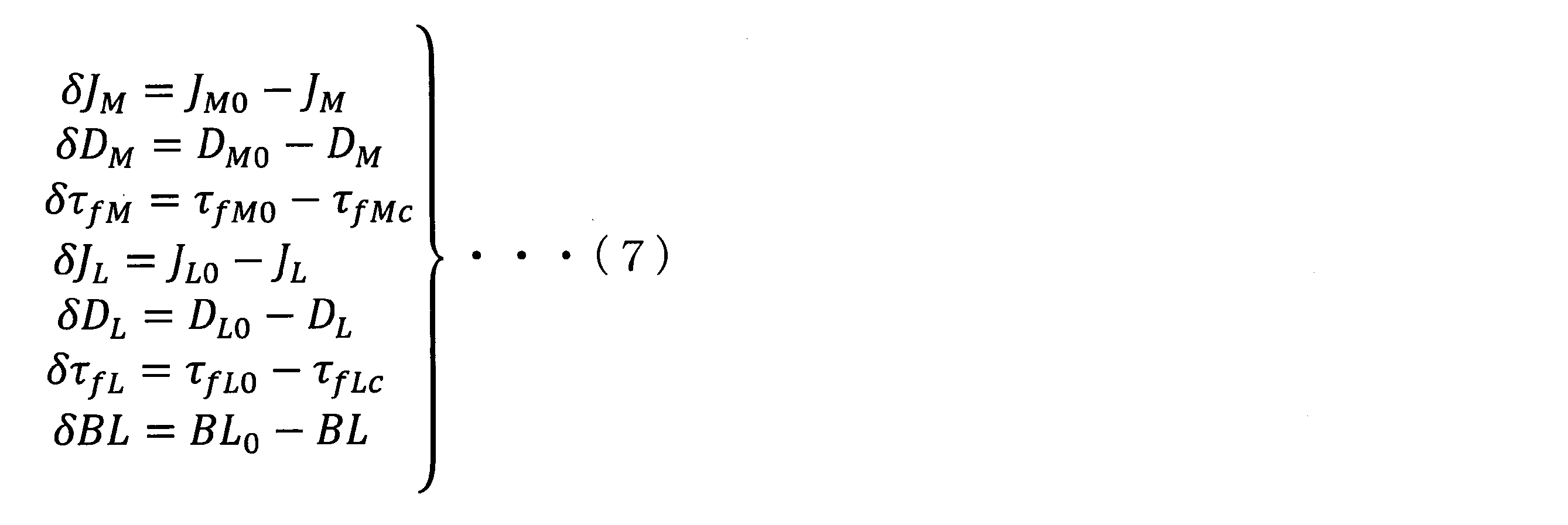
そうすると、図16に示すブロック線図に基づいて算出されたモータ側誤差信号eM及び負荷側誤差信号eLは、図17に示すブロック線図に基づいて、上記誤差成分パラメータ群(δJM、δDM、δτfM、δJL、δDL、δτfL、δBL)で表すことができる。
具体的には、モータ側誤差信号eMは、2慣性系モデルMODのうちモータ側のモデルをなす複数のモデルパラメータ群(JM0、DM0、τfM0、BL0)の各々に対応する誤差成分であるモータ側誤差パラメータ群(δJM、δDM、δτfM、δBL)に基づいて、式(8)のように表すことができる。

同様に、負荷側誤差信号eLは、2慣性系モデルMODのうち負荷側のモデルをなす複数のモデルパラメータ群(JL0、DL0、τfL0、BL0)の各々に対応する誤差成分である負荷側誤差パラメータ群(δJL、δDL、δτfL、δBL)に基づいて、式(9)のように表すことができる。

ここで、不感帯幅誤差成分δBLは、不感帯幅BLを示すモデルパラメータ(モデル不感帯幅BL0)に対応する誤差成分、即ち、2慣性系モデルMODとして規定されたモデル不感帯幅BL0と機械系2における実際の不感帯幅BLとの誤差である。
また、∂BKLS(θM-θL)/∂BL(図17に示す不感帯特性変化関数F2)は、不感帯幅誤差成分δBLが、上述した不感帯特性関数F1の特性に与える変化の度合いを表す非線形関数である。不感帯特性変化関数F2の詳細については後述する。
また、∂BKLS(θM-θL)/∂BL(図17に示す不感帯特性変化関数F2)は、不感帯幅誤差成分δBLが、上述した不感帯特性関数F1の特性に与える変化の度合いを表す非線形関数である。不感帯特性変化関数F2の詳細については後述する。
図17に示すブロック線図において、入力であるモータ角度θM、負荷角度θLと、出力であるモータ側誤差信号eM、負荷側誤差信号eLとは、図16を用いて説明した処理により、いずれも既知となっている。
本実施形態に係るモータ側エラーシステム123は、モータ側誤差パラメータ群(δJM、δDM、δτfM、δBL)の各々と、モータ側誤差信号eMと、を線形に関連付けるモータ側内部信号q0M、q1M、q2M及び不感帯用内部信号q3を出力する。
同様に、本実施形態に係る負荷側エラーシステム124は、負荷側誤差パラメータ群(δJL、δDL、δτfL、δBL)の各々と、負荷側誤差信号eLと、を線形に関連付ける負荷側内部信号q0L、q1L、q2L及び不感帯用内部信号q3を出力する。
なお、モータ側エラーシステム123が出力する不感帯用内部信号q3及び負荷側エラーシステム124が出力する不感帯用内部信号q3は同一であるが、説明の便宜上、モータ側エラーシステム123が出力する不感帯用内部信号q3をモータ側内部信号q3とも記載し、負荷側エラーシステム124が出力する不感帯用内部信号q3を負荷側内部信号q3とも記載する。
本実施形態に係るモータ側エラーシステム123は、モータ側誤差パラメータ群(δJM、δDM、δτfM、δBL)の各々と、モータ側誤差信号eMと、を線形に関連付けるモータ側内部信号q0M、q1M、q2M及び不感帯用内部信号q3を出力する。
同様に、本実施形態に係る負荷側エラーシステム124は、負荷側誤差パラメータ群(δJL、δDL、δτfL、δBL)の各々と、負荷側誤差信号eLと、を線形に関連付ける負荷側内部信号q0L、q1L、q2L及び不感帯用内部信号q3を出力する。
なお、モータ側エラーシステム123が出力する不感帯用内部信号q3及び負荷側エラーシステム124が出力する不感帯用内部信号q3は同一であるが、説明の便宜上、モータ側エラーシステム123が出力する不感帯用内部信号q3をモータ側内部信号q3とも記載し、負荷側エラーシステム124が出力する不感帯用内部信号q3を負荷側内部信号q3とも記載する。
ここで、モータ側内部信号q0M、q1M、q2M、q3は、入力であるモータ角度θM、負荷角度θL、及び、図17に示すブロック線図に基づいて、それぞれ、式(10)のように表される。

このようにして算出されたモータ側内部信号q0M、q1M、q2M、q3の各々は、モータ側誤差パラメータ群(δJM、δDM、δτfM、δBL)の各々と、モータ側誤差信号eMと、を線形に関連付けるパラメータとなる。
また、負荷側内部信号q0L、q1L、q2L、q3は、入力であるモータ角度θM、負荷角度θL、及び、図17に示すブロック線図に基づいて、それぞれ、式(11)のように表される。

このようにして算出された負荷側内部信号q0L、q1L、q2L、q3の各々は、負荷側誤差パラメータ群(δJL、δDL、δτfL、δBL)の各々と、負荷側誤差信号eLと、を線形に関連付けるパラメータとなる。
図18は、第2の実施形態に係るモータ側エラーシステム及び負荷側エラーシステムの処理を説明する第3の図である。
本実施形態に係るモータ側エラーシステム123、負荷側エラーシステム124は、上述したように、不感帯用内部信号q3を出力するにあたり、図18の(b)に示すような、予め用意された不感帯特性変化関数F2を用いる。上述したように、不感帯特性変化関数F2は、不感帯幅誤差成分δBLが、モータ20側から負荷21側へと動力が伝達する系の伝達特性(不感帯特性関数F1の特性)に与える変化の度合いを規定する非線形関数である。
本実施形態に係るモータ側エラーシステム123、負荷側エラーシステム124は、上述したように、不感帯用内部信号q3を出力するにあたり、図18の(b)に示すような、予め用意された不感帯特性変化関数F2を用いる。上述したように、不感帯特性変化関数F2は、不感帯幅誤差成分δBLが、モータ20側から負荷21側へと動力が伝達する系の伝達特性(不感帯特性関数F1の特性)に与える変化の度合いを規定する非線形関数である。
ここで、モータ20と負荷21との間に設けられた軸22の“遊び”の幅(不感帯幅BL)が、モデル不感帯幅BL0から所定の不感帯幅誤差成分δBL(δBL>0)だけ変化した場合を考える。この場合、不感帯特性関数F1は、図18の(a)に示すように、入力(θM-θL)に対し出力がゼロとなる領域が、正負方向に+δBL、-δBLだけ広がる。その結果、入力(θM-θL)が+BL0より大きい領域(θM-θL>BL0)においては、出力(縦軸)が-δBLだけ変化する。また、入力(θM-θL)が-BL0より小さい領域(θM-θL<-BL0)においては、出力(縦軸)が+δBLだけ変化する。
また、不感帯特性関数F1において、不感帯幅BLがBL0であった場合には、入力(θM-θL)がBL0を上回った時点で出力が上昇するのに対し、不感帯幅BLが(BL0+δBL)に変化すると、入力(θM-θL)が(BL0+δBL)を上回るまでは、出力は“ゼロ”のままである。したがって、入力(θM-θL)がBL0から(BL0+δBL)までの範囲においては、入力(θM-θL)と、出力のマイナス方向への変化の度合いと、が比例関係にある。同様に、入力(θM-θL)が-BL0から(-BL0-δBL)までの範囲においては、入力(θM-θL)と、出力のプラス方向への変化の度合いと、が比例関係にある。
また、入力(θM-θL)がBL0から-BL0までの領域は、不感帯幅BLにおけるBL0から(BL0+δBL)への変化に関わらず、出力は“ゼロ”のままである。つまり、不感帯幅BLがBL0から(BL0+δBL)へ変化しても、出力は変化しない。
また、入力(θM-θL)がBL0から-BL0までの領域は、不感帯幅BLにおけるBL0から(BL0+δBL)への変化に関わらず、出力は“ゼロ”のままである。つまり、不感帯幅BLがBL0から(BL0+δBL)へ変化しても、出力は変化しない。
以上より、不感帯幅誤差成分δBLが、不感帯特性関数F1の特性に与える変化の度合いを表す不感帯特性変化関数F2は、図18の(b)に示すような非線形特性によって表すことができる。
即ち、入力(θM-θL)がBL0+δBL’を上回る領域においては、不感帯特性関数F1による出力がマイナス方向に変化するので、不感帯特性変化関数F2は、“-1”を出力する。同様に、入力(θM-θL)が-BL0-δBL’を下回る領域においては、不感帯特性関数F1による出力がプラス方向に変化するので、不感帯特性変化関数F2は、“+1”を出力する。
また、入力(θM-θL)がBL0から(BL0+δBL’)までの領域においては、入力(θM-θL)の増加に応じて、出力が“ゼロ”から“-1”まで徐々に減少するように変化する。同様に、入力(θM-θL)が-BL0から(-BL0-δBL’)までの領域においては、入力(θM-θL)の減少に応じて、出力が“ゼロ”から“+1”まで徐々に増加するように変化する。
そして、入力(θM-θL)がBL0から-BL0までの領域においては、不感帯特性関数F1の出力は変化しないので、不感帯特性変化関数F2は、“ゼロ”を出力する。
なお、定数δBL’は、想定される不感帯幅誤差成分δBLを予め予測して定めた定数であり、例えば、モデル不感帯幅BL0の20%程度(δBL’=0.2×BL0)とされる。
即ち、入力(θM-θL)がBL0+δBL’を上回る領域においては、不感帯特性関数F1による出力がマイナス方向に変化するので、不感帯特性変化関数F2は、“-1”を出力する。同様に、入力(θM-θL)が-BL0-δBL’を下回る領域においては、不感帯特性関数F1による出力がプラス方向に変化するので、不感帯特性変化関数F2は、“+1”を出力する。
また、入力(θM-θL)がBL0から(BL0+δBL’)までの領域においては、入力(θM-θL)の増加に応じて、出力が“ゼロ”から“-1”まで徐々に減少するように変化する。同様に、入力(θM-θL)が-BL0から(-BL0-δBL’)までの領域においては、入力(θM-θL)の減少に応じて、出力が“ゼロ”から“+1”まで徐々に増加するように変化する。
そして、入力(θM-θL)がBL0から-BL0までの領域においては、不感帯特性関数F1の出力は変化しないので、不感帯特性変化関数F2は、“ゼロ”を出力する。
なお、定数δBL’は、想定される不感帯幅誤差成分δBLを予め予測して定めた定数であり、例えば、モデル不感帯幅BL0の20%程度(δBL’=0.2×BL0)とされる。
次に、本実施形態に係るパラメータ同定部122(図15参照)の機能について説明する。
パラメータ同定部122は、モータ側エラーシステム123によって算出されたモータ側誤差信号eM(図16参照)と、同じくモータ側エラーシステム123によって算出されたモータ側内部信号q0M、q1M、q2M、q3(図17参照)と、を入力する。
パラメータ同定部122は、モータ側エラーシステム123によって算出されたモータ側誤差信号eM(図16参照)と、同じくモータ側エラーシステム123によって算出されたモータ側内部信号q0M、q1M、q2M、q3(図17参照)と、を入力する。
パラメータ同定部122は、モータ側内部信号q0M、q1M、q2M、q3の各々が、未知のモータ側誤差パラメータ群(δJM、δDM、δτfM、δBL)の各々と、モータ側誤差信号eMとを、式(12)のように、線形に関連付けていることを利用して、上記未知のモータ側誤差パラメータ群の各々を算出する。

ここで、パラメータ同定部122は、機械系2における周期的動作のうちの一周期Tに当たるモータ側誤差信号eMとモータ側内部信号q0M、q1M、q2M、q3とを取得する。そして、式(12)の両辺にモータ側内部信号q0M、q1M、q2M、q3を乗じ、更に、両辺を一周期T分だけ時間積分すると、式(13)のように変形される。

更に、式(13)は、式(14)に変形される。

これにより、パラメータ同定部122は、式(15)に従って、未知のモータ側誤差パラメータ群(δJM、δDM、δτfM、δBL)を算出することができる。

パラメータ同定部122は、算出されたモータ側誤差パラメータ群(δJM、δDM、δτfM、δBL)の各々を、モータ側のモデルをなすモデルパラメータ群(JM0、DM0、τfM0、BL0)の各々から減算することで、新たなモデルパラメータ群(JM0、DM0、τfM0、BL0)を同定する。
更に、パラメータ同定部122は、負荷側エラーシステム124によって算出されたモータ側誤差信号eL(図16参照)と、同じく負荷側エラーシステム124によって算出された負荷側内部信号q0L、q1L、q2L、q3(図17参照)と、を入力する。
パラメータ同定部122は、負荷側内部信号q0L、q1L、q2L、q3の各々が、未知の負荷側誤差パラメータ群(δJL、δDL、δτfL、δBL)の各々と、負荷側誤差信号eLとを、式(16)のように、線形に関連付けていることを利用して、上記未知の負荷側誤差パラメータ群の各々を算出する。

ここで、パラメータ同定部122は、機械系2における周期的動作のうちの一周期Tに当たる負荷側誤差信号eLと負荷側内部信号q0L、q1L、q2L、q3とを取得する。そして、式(16)の両辺に負荷側内部信号q0L、q1L、q2L、q3を乗じ、更に、両辺を一周期T分だけ時間積分すると、式(17)のように変形される。

更に、式(17)は、式(18)に変形される。

これにより、パラメータ同定部122は、式(19)に従って、未知の負荷側誤差パラメータ群(δJL、δDL、δτfL、δBL)を算出することができる。

パラメータ同定部122は、算出された負荷側誤差パラメータ群(δJL、δDL、δτfL、δBL)の各々を、予め規定されていた負荷側のモデルをなすモデルパラメータ群(JL0、DL0、τfL0、BL0)の各々から減算することで、新たなモデルパラメータ群(JL0、DL0、τfL0、BL0)を同定する。
なお、本実施形態に係るパラメータ同定部122は、機械系2における周期的動作のうちの一周期T分のモータ側誤差信号eM、負荷側誤差信号eLと、同じ一周期T分の各種内部信号q0M、q1M、q2M、q0L、q1L、q2L、q3とを取得して、誤差信号と誤差パラメータ群との関係式(式(12)、式(16))を一周期Tで時間積分している。
このようにすることで、一周期Tの時間積分により未知の外乱がキャンセルされ得るため、誤差パラメータ群(δJM、δDM、δτfM、δJL、δDL、δτfL、δBL)を精度良く算出することができる。
このようにすることで、一周期Tの時間積分により未知の外乱がキャンセルされ得るため、誤差パラメータ群(δJM、δDM、δτfM、δJL、δDL、δτfL、δBL)を精度良く算出することができる。
図19は、第2の実施形態に係るパラメータ同定装置の処理フローを示す図である。 図19に示す処理フローは、例えば、第1の実施形態(図7)と同様に、機械系2の実運転の開始前等において、パラメータ同定装置12(図15)が機械系2についてのパラメータ同定を行う際に実行される。
パラメータ同定装置12は、ステップS01~ステップS04を経て、小振幅、低周波数の反復動作中に取得された各種実測データ(ωM、θM、ωL、θL、τ)に基づき、モデルモータ側摩擦係数τfM0、モデル負荷側摩擦係数τfL0、モデル不感帯幅BL0、モデルねじれ剛性係数KR0を同定する。図19に示すステップS01~ステップS04の各処理は、第1の実施形態(図7)と同様であるため説明を省略する。
次に、モータ制御システム1のオペレータは、上位機器を操作して所定の角度指令値を出力させることで、負荷21の角度(負荷角度θL)を大振幅かつ高周波数で反復動作させる(ステップS11)。
次に、パラメータ同定装置12のデータ取得部120は、大振幅かつ高周波数で反復動作中の機械系2から、モータ角速度ωM、モータ角度θM、負荷角速度ωL及び負荷角度θLの経時的変化を示す実測データを取得する(ステップS12)。
次に、パラメータ同定装置12のモータ側エラーシステム123は、図16~図18で説明した処理を経てモータ側誤差信号eM、及び、モータ側内部信号q0M、q1M、q2M及び不感帯用内部信号q3を出力する。また、パラメータ同定装置12の負荷側エラーシステム124は、図16~図18で説明した処理を経て負荷側誤差信号eL、及び、負荷側内部信号q0L、q1L、q2L及び不感帯用内部信号q3を出力する(ステップS13)。
次に、パラメータ同定部122は、モータ側エラーシステム123及び負荷側エラーシステム124から入力した各種誤差信号、内部信号に基づいて、モータ側誤差パラメータ群(δJM、δDM、δτfM、δBL)、及び、負荷側誤差パラメータ群(δJL、δDL、δτfL、δBL)を算出する。そして、パラメータ同定部122は、これらの誤差パラメータ群に基づいて、ステップS04で同定されていなかった残りのモデルパラメータを同定する(ステップS14)。
具体的には、パラメータ同定部122は、ステップS14において、モデルモータ側慣性モーメントJM0、モデルモータ側粘性係数DM0、モデル負荷側慣性モーメントJL0、及び、モデル負荷側粘性係数DL0を同定する。
具体的には、パラメータ同定部122は、ステップS14において、モデルモータ側慣性モーメントJM0、モデルモータ側粘性係数DM0、モデル負荷側慣性モーメントJL0、及び、モデル負荷側粘性係数DL0を同定する。
(作用、効果)
以上のように、第2の実施形態に係るパラメータ同定装置12は、機械系2が行う反復動作の振幅及び周波数が相対的に小振幅かつ低周波数の場合に同定を行う第1ステップと、機械系2が行う反復動作の振幅及び周波数が相対的に大振幅かつ高周波数の場合に同定を行う第2ステップと、に分けてモデルパラメータの同定を行う。
より詳細には、パラメータ同定部122は、第1ステップにおいて取得されたトルクτと、モータ20の角度及び角速度の実測データと、負荷21の角度及び角速度の実測データと、に基づいて、モータの摩擦、負荷の摩擦、軸22の剛性、及び、軸22の不感帯幅を示すモデルパラメータを同定する。
そして、パラメータ同定部122は、第2ステップにおいて取得されたトルクτと、モータ20の角度の実測データと、負荷21の角度の実測データと、に基づいて、モータ20の慣性モーメント及び粘性係数を示すモデルパラメータ(モデルモータ側慣性モーメントJM0、モデルモータ側粘性係数DM0)、及び、負荷21の慣性モーメント及び粘性係数を示すモデルパラメータ(モデル負荷側慣性モーメントJL0、及び、モデル負荷側粘性係数DL0)を同定する。
以上のように、第2の実施形態に係るパラメータ同定装置12は、機械系2が行う反復動作の振幅及び周波数が相対的に小振幅かつ低周波数の場合に同定を行う第1ステップと、機械系2が行う反復動作の振幅及び周波数が相対的に大振幅かつ高周波数の場合に同定を行う第2ステップと、に分けてモデルパラメータの同定を行う。
より詳細には、パラメータ同定部122は、第1ステップにおいて取得されたトルクτと、モータ20の角度及び角速度の実測データと、負荷21の角度及び角速度の実測データと、に基づいて、モータの摩擦、負荷の摩擦、軸22の剛性、及び、軸22の不感帯幅を示すモデルパラメータを同定する。
そして、パラメータ同定部122は、第2ステップにおいて取得されたトルクτと、モータ20の角度の実測データと、負荷21の角度の実測データと、に基づいて、モータ20の慣性モーメント及び粘性係数を示すモデルパラメータ(モデルモータ側慣性モーメントJM0、モデルモータ側粘性係数DM0)、及び、負荷21の慣性モーメント及び粘性係数を示すモデルパラメータ(モデル負荷側慣性モーメントJL0、及び、モデル負荷側粘性係数DL0)を同定する。
ここで、小振幅、低周波数の状態であれば、慣性モーメント及び粘性係数の影響が小さく、モータ20、負荷21の摩擦、軸22の剛性及び不感帯幅の特性を捉えやすい。他方、大振幅、高周波数の状態であれば、モータ20、負荷21の摩擦、軸22の剛性及び不感帯幅の影響が小さくなり、慣性モーメント及び粘性係数の特性を捉えやすくなる。
そこで、上述のような2段階のステップを実施する態様とすることで、2慣性系モデルMODを構成する全てのパラメータを高精度に同定することができる。
そこで、上述のような2段階のステップを実施する態様とすることで、2慣性系モデルMODを構成する全てのパラメータを高精度に同定することができる。
また、上述の各実施形態においては、モータ制御システム1におけるパラメータ同定装置12の機能を実現するためのプログラムをコンピュータ読み取り可能な記録媒体に記録して、この記録媒体に記録されたプログラムをコンピュータシステムに読み込ませ、実行することにより各手順を行うものとしている。ここで、上述したパラメータ同定装置12の各処理の過程は、プログラムの形式でコンピュータ読み取り可能な記録媒体に記憶されており、このプログラムをコンピュータが読み出して実行することによって上記各種処理が行われる。ここで、コンピュータ読み取り可能な記録媒体とは、磁気ディスク、光磁気ディスク、CD-ROM、DVD-ROM、半導体メモリ等をいう。また、このコンピュータプログラムを通信回線によってコンピュータに配信し、この配信を受けたコンピュータが当該プログラムを実行するようにしても良い。
また、パラメータ同定装置12の機能が、ネットワークで接続される複数の装置に渡って具備される態様であってもよい。
また、パラメータ同定装置12の機能が、ネットワークで接続される複数の装置に渡って具備される態様であってもよい。
以上、本発明のいくつかの実施形態を説明したが、これらの実施形態は、例として示したものであり、発明の範囲を限定することは意図していない。これら実施形態は、その他の様々な形態で実施されることが可能であり、発明の要旨を逸脱しない範囲で種々の省略、置き換え、変更を行うことができる。これら実施形態やその変形は、発明の範囲や要旨に含まれると同様に、特許請求の範囲に記載された発明とその均等の範囲に含まれるものとする。
上述のパラメータ同定装置、モータ制御システム、パラメータ同定方法及びプログラムによれば、モータ及び負荷を有する機械系を精度よく模したモデルを得ることができる。
1 モータ制御システム
10 フィードバック制御部
11 フィードフォワード制御部
12 パラメータ同定装置
120 データ取得部
121 位相面図生成部
122 パラメータ同定部
123 モータ側エラーシステム
124 負荷側エラーシステム
2 機械系
20 モータ
21 負荷
22 軸
θt 目標角度(目標回転角度)
τ、τ’ トルク
θM モータ角度(モータの角度)
ωM モータ角速度(モータの角速度)
JM モータ側慣性モーメント
DM モータ側粘性係数
τfM モータ側摩擦係数
τfMc モータ側クーロン摩擦係数
θL 負荷角度(負荷の角度)
ωL 負荷角速度(負荷の角速度)
JL 負荷側慣性モーメント
DL 負荷側粘性係数
τfL 負荷側摩擦係数
τfLc 負荷側クーロン摩擦係数
KR ねじれ剛性係数
DR ねじれ粘性係数
BL 不感帯幅
MOD 2慣性系モデル
JM0 モデルモータ側慣性モーメント
DM0 モデルモータ側粘性係数
τfM0 モデルモータ側摩擦係数
τfMc0 モデルモータ側クーロン摩擦係数
JL0 モデル負荷側慣性モーメント
DL0 モデル負荷側粘性係数
τfL0 モデル負荷側摩擦係数
τfLc0 モデル負荷側クーロン摩擦係数
BL0 モデル不感帯幅
KR0 モデルねじれ剛性係数
eM モータ側誤差信号
eL 負荷側誤差信号
δJM モータ側慣性モーメント誤差成分
δDM モータ側粘性係数誤差成分
δτfM モータ側摩擦係数誤差成分
δJL 負荷側慣性モーメント誤差成分
δDL 負荷側粘性係数誤差成分
δτfL 負荷側摩擦係数誤差成分
δBL 不感帯幅誤差成分
q0M、q1M、q2M モータ側内部信号
q0L、q1L、q2L 負荷側内部信号
q3 不感帯用内部信号(モータ側内部信号、負荷側内部信号)
S1、S2 符号関数
F1 不感帯特性関数
F1’ ガタ変位関数
F2 不感帯特性変化関数
GM モータ側摩擦特性関数
GL 負荷側摩擦特性関数
P1 ねじれ角度-トルク位相面図
P2 トルク-機械角速度位相面図
P3 ねじれ角度-機械角速度位相面図
P4 トルク-ねじれ速度位相面図
P5 ねじれ角度-ねじれ速度位相面図
P6 負荷角度-トルク位相面図
10 フィードバック制御部
11 フィードフォワード制御部
12 パラメータ同定装置
120 データ取得部
121 位相面図生成部
122 パラメータ同定部
123 モータ側エラーシステム
124 負荷側エラーシステム
2 機械系
20 モータ
21 負荷
22 軸
θt 目標角度(目標回転角度)
τ、τ’ トルク
θM モータ角度(モータの角度)
ωM モータ角速度(モータの角速度)
JM モータ側慣性モーメント
DM モータ側粘性係数
τfM モータ側摩擦係数
τfMc モータ側クーロン摩擦係数
θL 負荷角度(負荷の角度)
ωL 負荷角速度(負荷の角速度)
JL 負荷側慣性モーメント
DL 負荷側粘性係数
τfL 負荷側摩擦係数
τfLc 負荷側クーロン摩擦係数
KR ねじれ剛性係数
DR ねじれ粘性係数
BL 不感帯幅
MOD 2慣性系モデル
JM0 モデルモータ側慣性モーメント
DM0 モデルモータ側粘性係数
τfM0 モデルモータ側摩擦係数
τfMc0 モデルモータ側クーロン摩擦係数
JL0 モデル負荷側慣性モーメント
DL0 モデル負荷側粘性係数
τfL0 モデル負荷側摩擦係数
τfLc0 モデル負荷側クーロン摩擦係数
BL0 モデル不感帯幅
KR0 モデルねじれ剛性係数
eM モータ側誤差信号
eL 負荷側誤差信号
δJM モータ側慣性モーメント誤差成分
δDM モータ側粘性係数誤差成分
δτfM モータ側摩擦係数誤差成分
δJL 負荷側慣性モーメント誤差成分
δDL 負荷側粘性係数誤差成分
δτfL 負荷側摩擦係数誤差成分
δBL 不感帯幅誤差成分
q0M、q1M、q2M モータ側内部信号
q0L、q1L、q2L 負荷側内部信号
q3 不感帯用内部信号(モータ側内部信号、負荷側内部信号)
S1、S2 符号関数
F1 不感帯特性関数
F1’ ガタ変位関数
F2 不感帯特性変化関数
GM モータ側摩擦特性関数
GL 負荷側摩擦特性関数
P1 ねじれ角度-トルク位相面図
P2 トルク-機械角速度位相面図
P3 ねじれ角度-機械角速度位相面図
P4 トルク-ねじれ速度位相面図
P5 ねじれ角度-ねじれ速度位相面図
P6 負荷角度-トルク位相面図
Claims (12)
- モータと負荷とが連結部材にて連結されてなる機械系を模した2慣性系モデルのモデルパラメータを同定するパラメータ同定装置であって、
前記モータに対するトルク指令値と、前記モータの角度及び角速度の実測データと、前記負荷の角度及び角速度の実測データと、を取得するデータ取得部と、
取得された前記トルク指令値と、前記モータの角度及び角速度の実測データと、前記負荷の角度及び角速度の実測データと、に基づいて複数の位相面図を生成する位相面図生成部と、
生成された複数の前記位相面図に基づいて、前記モータの摩擦、前記負荷の摩擦、前記連結部材の剛性、及び、前記連結部材の不感帯幅を示すモデルパラメータを同定するパラメータ同定部と、
を備えるパラメータ同定装置。 - 前記位相面図生成部は、前記位相面図として、前記トルク指令値と前記連結部材のねじれ速度との関係を示すトルク-ねじれ速度位相面図を生成し、
前記パラメータ同定部は、前記トルク-ねじれ位相面図における折れ点の位置に基づいて前記モータの摩擦を示すモデルパラメータを同定する
請求項1に記載のパラメータ同定装置。 - 前記位相面図生成部は、前記位相面図として、前記連結部材のねじれ角度と前記連結部材のねじれ速度との関係を示すねじれ角度-ねじれ速度位相面図を生成し、
前記パラメータ同定部は、前記ねじれ角度-ねじれ速度位相面図における折れ点の位置に基づいて前記連結部材の剛性、及び、前記連結部材の不感帯幅を示すモデルパラメータを同定する
請求項1又は請求項2に記載のパラメータ同定装置。 - 前記位相面図生成部は、前記位相面図として、前記トルク指令値と、前記モータの角速度及び前記負荷の角速度のうちの少なくとも何れか一つとの関係を示すトルク-機械角速度位相面図を生成し、
前記パラメータ同定部は、前記トルク-機械角速度位相面図における折れ点の位置に基づいて前記負荷の摩擦を示すモデルパラメータを同定する
請求項1から請求項3の何れか一項に記載のパラメータ同定装置。 - 前記位相面図生成部は、前記位相面図として、前記負荷の角度と前記トルク指令値との関係を示す負荷角度-トルク位相面図を生成し、
前記パラメータ同定部は、前記負荷角度-トルク位相面図における折れ点の位置に基づいて前記負荷の摩擦を示すモデルパラメータを同定する
請求項1から請求項4の何れか一項に記載のパラメータ同定装置。 - 前記位相面図生成部は、前記位相面図として、前記連結部材のねじれ角度と前記トルク指令値との関係を示すねじれ角度-トルク位相面図を生成し、
前記パラメータ同定部は、前記ねじれ角度-トルク位相面図における折れ点の位置に基づいて、前記モータの摩擦、前記負荷の摩擦、前記連結部材の剛性、及び、前記連結部材の不感帯幅のうちの少なくとも何れか一つを示すモデルパラメータを同定する
請求項1から請求項4の何れか一項に記載のパラメータ同定装置。 - 前記トルク指令値、前記モータの角度、及び、前記負荷の角度の実測データに基づいて、前記2慣性系モデルのうちモータ側のモデルの、前記モータに対する誤差の度合いを示すモータ側誤差信号を出力するモータ側エラーシステムと、
前記モータの角度、及び、前記負荷の角度の実測データに基づいて、前記2慣性系モデルのうち負荷側のモデルの、前記負荷に対する誤差の度合いを示す負荷側誤差信号を出力する負荷側エラーシステムと、
を更に備え、
前記パラメータ同定部は、
前記モータ側誤差信号を入力して、少なくとも前記モータの慣性モーメント及び粘性係数を示すモデルパラメータを同定し、かつ、前記負荷側誤差信号を入力して、少なくとも前記負荷の慣性モーメント及び粘性係数を示すモデルパラメータを同定する
請求項1から請求項6の何れか一項に記載のパラメータ同定装置。 - 前記パラメータ同定部は、
前記機械系が行う反復動作の振幅及び周波数が相対的に小振幅かつ低周波数の場合に取得された前記トルク指令値と、前記モータの角度及び角速度の実測データと、前記負荷の角度及び角速度の実測データと、に基づいて、前記モータの摩擦、前記負荷の摩擦、前記連結部材の剛性、及び、前記連結部材の不感帯幅を示すモデルパラメータを同定し、
前記機械系が行う反復動作の振幅及び周波数が相対的に大振幅かつ高周波数の場合に取得された前記トルク指令値と、前記モータの角度の実測データと、前記負荷の角度の実測データと、に基づいて、前記モータの慣性モーメント及び粘性係数を示すモデルパラメータ、及び、前記負荷の慣性モーメント及び粘性係数を示すモデルパラメータを同定する 請求項7に記載のパラメータ同定装置。 - モータと負荷とが連結部材にて連結されてなる機械系を模した2慣性系モデルのモデルパラメータを同定するパラメータ同定装置であって、
前記モータに対するトルク指令値と、前記モータの角度の実測データと、前記負荷の角度の実測データと、を取得するデータ取得部と、
取得された前記トルク指令値と、前記モータの角度の実測データと、前記負荷の角度の実測データと、に基づいて、前記連結部材のねじれ角度と前記トルク指令値との関係を示すねじれ角度-トルク位相面図を生成する位相面図生成部と、
生成された前記ねじれ角度-トルク位相面図に基づいて、前記モータの摩擦、前記負荷の摩擦、前記連結部材の剛性、及び、前記連結部材の不感帯幅を示すモデルパラメータを同定するパラメータ同定部と、
を備えるパラメータ同定装置。 - 請求項1から請求項9の何れか一項に記載のパラメータ同定装置と、
前記負荷の目標とする角度に対する現在の角度の偏差に基づいて、前記トルク指令値を算出するフィードバック制御部と、
前記パラメータ同定装置によって同定された前記モデルパラメータに基づいて、前記トルク指令値を算出するフィードフォワード制御部と、
を備えるモータ制御システム。 - モータと負荷とが連結部材にて連結されてなる機械系を模した2慣性系モデルのモデルパラメータを同定するパラメータ同定方法であって、
前記モータに対するトルク指令値と、前記モータの角度及び角速度の実測データと、前記負荷の角度及び角速度の実測データと、を取得するステップと、
取得された前記トルク指令値と、前記モータの角度及び角速度の実測データと、前記負荷の角度及び角速度の実測データと、に基づいて複数の位相面図を生成するステップと、 生成された複数の前記位相面図に基づいて、前記モータの摩擦、前記負荷の摩擦、前記連結部材の剛性、及び、前記連結部材の不感帯幅を示すモデルパラメータを同定するステップと、
を有するパラメータ同定方法。 - モータと負荷とが連結部材にて連結されてなる機械系を模した2慣性系モデルのモデルパラメータを同定するパラメータ同定装置のコンピュータを、
前記モータに対するトルク指令値と、前記モータの角度及び角速度の実測データと、前記負荷の角度及び角速度の実測データと、を取得するデータ取得部、
取得された前記トルク指令値と、前記モータの角度及び角速度の実測データと、前記負荷の角度及び角速度の実測データと、に基づいて複数の位相面図を生成する位相面図生成部、
生成された複数の前記位相面図に基づいて、前記モータの摩擦、前記負荷の摩擦、前記連結部材の剛性、及び、前記連結部材の不感帯幅を示すモデルパラメータを同定するパラメータ同定部、
として機能させるプログラム。
Applications Claiming Priority (2)
| Application Number | Priority Date | Filing Date | Title |
|---|---|---|---|
| JP2016104481A JP6710103B2 (ja) | 2016-05-25 | 2016-05-25 | パラメータ同定装置、モータ制御システム、パラメータ同定方法及びプログラム |
| JP2016-104481 | 2016-05-25 |
Publications (1)
| Publication Number | Publication Date |
|---|---|
| WO2017203987A1 true WO2017203987A1 (ja) | 2017-11-30 |
Family
ID=60412212
Family Applications (1)
| Application Number | Title | Priority Date | Filing Date |
|---|---|---|---|
| PCT/JP2017/017827 Ceased WO2017203987A1 (ja) | 2016-05-25 | 2017-05-11 | パラメータ同定装置、モータ制御システム、パラメータ同定方法及びプログラム |
Country Status (2)
| Country | Link |
|---|---|
| JP (1) | JP6710103B2 (ja) |
| WO (1) | WO2017203987A1 (ja) |
Cited By (3)
| Publication number | Priority date | Publication date | Assignee | Title |
|---|---|---|---|---|
| CN111123834A (zh) * | 2019-12-26 | 2020-05-08 | 西安交通大学 | 一种直线电机进给系统机电耦合强度评价方法 |
| CN112039051A (zh) * | 2020-06-30 | 2020-12-04 | 长沙理工大学 | 一种含双馈风力发电机接入变电站母线负荷的实时建模方法 |
| CN119578000A (zh) * | 2025-02-08 | 2025-03-07 | 浙江大学 | 一种多模态液压马达低速重载摩擦转矩参数辨识方法及装置 |
Families Citing this family (5)
| Publication number | Priority date | Publication date | Assignee | Title |
|---|---|---|---|---|
| JP7190947B2 (ja) * | 2019-03-22 | 2022-12-16 | 三菱重工機械システム株式会社 | 油圧制御システムにおけるパラメータ同定を行う装置と方法、油圧制御システム、および状態検知方法 |
| DE112020003348T5 (de) * | 2019-08-09 | 2022-03-24 | Miki Pulley Co., Ltd. | Kennlinienauswertevorrichtung und Kennlinienauswerteverfahren von einer Wellenkupplung |
| JP2022150876A (ja) * | 2021-03-26 | 2022-10-07 | 株式会社アイシン | シフト装置 |
| CN114879483B (zh) * | 2022-06-15 | 2024-04-30 | 中国电子科技集团公司第三十八研究所 | 机载sar大承载偏心一轴平台pi比例参数自整定方法 |
| CN115639854B (zh) * | 2022-09-27 | 2024-11-26 | 北京无线电测量研究所 | 一种雷达伺服系统俯仰负载质心位置辨识方法 |
Citations (3)
| Publication number | Priority date | Publication date | Assignee | Title |
|---|---|---|---|---|
| JP2003506786A (ja) * | 1999-08-09 | 2003-02-18 | フィッシャー コントロールズ インターナショナル, インコーポレイテッド | プロセス制御ループパラメータの推定値の統計的に決定する方法 |
| WO2009104676A1 (ja) * | 2008-02-20 | 2009-08-27 | ブラザー工業株式会社 | 送り駆動装置のバックラッシ量検知方法、及び送り駆動装置のバックラッシ量検知装置 |
| JP2013128387A (ja) * | 2011-07-27 | 2013-06-27 | Fanuc Ltd | イナーシャと摩擦係数とばね定数を同時に推定する機能を備える電動機の制御装置 |
-
2016
- 2016-05-25 JP JP2016104481A patent/JP6710103B2/ja active Active
-
2017
- 2017-05-11 WO PCT/JP2017/017827 patent/WO2017203987A1/ja not_active Ceased
Patent Citations (3)
| Publication number | Priority date | Publication date | Assignee | Title |
|---|---|---|---|---|
| JP2003506786A (ja) * | 1999-08-09 | 2003-02-18 | フィッシャー コントロールズ インターナショナル, インコーポレイテッド | プロセス制御ループパラメータの推定値の統計的に決定する方法 |
| WO2009104676A1 (ja) * | 2008-02-20 | 2009-08-27 | ブラザー工業株式会社 | 送り駆動装置のバックラッシ量検知方法、及び送り駆動装置のバックラッシ量検知装置 |
| JP2013128387A (ja) * | 2011-07-27 | 2013-06-27 | Fanuc Ltd | イナーシャと摩擦係数とばね定数を同時に推定する機能を備える電動機の制御装置 |
Cited By (3)
| Publication number | Priority date | Publication date | Assignee | Title |
|---|---|---|---|---|
| CN111123834A (zh) * | 2019-12-26 | 2020-05-08 | 西安交通大学 | 一种直线电机进给系统机电耦合强度评价方法 |
| CN112039051A (zh) * | 2020-06-30 | 2020-12-04 | 长沙理工大学 | 一种含双馈风力发电机接入变电站母线负荷的实时建模方法 |
| CN119578000A (zh) * | 2025-02-08 | 2025-03-07 | 浙江大学 | 一种多模态液压马达低速重载摩擦转矩参数辨识方法及装置 |
Also Published As
| Publication number | Publication date |
|---|---|
| JP6710103B2 (ja) | 2020-06-17 |
| JP2017211829A (ja) | 2017-11-30 |
Similar Documents
| Publication | Publication Date | Title |
|---|---|---|
| WO2017203987A1 (ja) | パラメータ同定装置、モータ制御システム、パラメータ同定方法及びプログラム | |
| Iskandar et al. | Dynamic friction model with thermal and load dependency: modeling, compensation, and external force estimation | |
| CN110460277A (zh) | 基于粒子群算法的单电机伺服系统摩擦非线性补偿方法 | |
| CN105619424B (zh) | 电机驱动设备的控制设备及方法、多轴电机的控制设备 | |
| JP6762276B2 (ja) | 移動軌跡成形装置、異常診断システム、移動軌跡成形方法及びプログラム | |
| JP4914979B2 (ja) | モータ制御装置およびモータ制御方法 | |
| JP7305113B2 (ja) | モータ制御装置、モータ装置および機械学習装置 | |
| JP2014136260A (ja) | 制御装置 | |
| JP2014052912A (ja) | 動力伝達装置 | |
| Mola et al. | Identification and adaptive position control of two mass systems with unknown backlash | |
| CN107351086A (zh) | 一种scara机器人关节力矩的卡尔曼估计方法 | |
| Madsen et al. | Model-based on-line estimation of time-varying nonlinear joint stiffness on an e-series universal robots manipulator | |
| CN104678763B (zh) | 基于最小二乘支持向量机的机电伺服系统摩擦补偿和动态面控制方法 | |
| JP6756568B2 (ja) | 制御装置、駆動システム、制御方法及びプログラム | |
| US11791751B2 (en) | Motor control system, motor control method, and program | |
| JP6756653B2 (ja) | パラメータ同定装置、駆動システム、パラメータ同定方法及びプログラム | |
| JP3652202B2 (ja) | 位置制御方法及び位置制御装置 | |
| JP7120821B2 (ja) | 制御装置、制御方法及びプログラム | |
| JP5411687B2 (ja) | ロボットの制御装置 | |
| CN111025915B (zh) | 一种基于干扰观测器的z轴陀螺仪神经网络滑模控制方法 | |
| Mahapatra et al. | Estimation of torque variation due to torsional vibration in a rotating system using a kalman filter-based approach | |
| JP7343308B2 (ja) | 情報処理装置、工作機械、ロボット、情報処理装置の制御方法および情報処理装置の制御プログラム | |
| JP2011015550A (ja) | 機械装置の制御装置及び機械装置の特性同定方法 | |
| JP2022039922A (ja) | 加工抵抗推定の適応化方法、加工抵抗推定の適応化プログラムおよび工作機械 | |
| CN113084828B (zh) | 一种运动控制方法、装置、设备和存储介质 |
Legal Events
| Date | Code | Title | Description |
|---|---|---|---|
| NENP | Non-entry into the national phase |
Ref country code: DE |
|
| 121 | Ep: the epo has been informed by wipo that ep was designated in this application |
Ref document number: 17802582 Country of ref document: EP Kind code of ref document: A1 |
|
| 122 | Ep: pct application non-entry in european phase |
Ref document number: 17802582 Country of ref document: EP Kind code of ref document: A1 |