WO2017203894A1 - 表示装置および表示装置の制御方法 - Google Patents
表示装置および表示装置の制御方法 Download PDFInfo
- Publication number
- WO2017203894A1 WO2017203894A1 PCT/JP2017/015499 JP2017015499W WO2017203894A1 WO 2017203894 A1 WO2017203894 A1 WO 2017203894A1 JP 2017015499 W JP2017015499 W JP 2017015499W WO 2017203894 A1 WO2017203894 A1 WO 2017203894A1
- Authority
- WO
- WIPO (PCT)
- Prior art keywords
- light
- display
- excitation light
- excitation
- light source
- Prior art date
- Legal status (The legal status is an assumption and is not a legal conclusion. Google has not performed a legal analysis and makes no representation as to the accuracy of the status listed.)
- Ceased
Links
Images







Classifications
-
- C—CHEMISTRY; METALLURGY
- C09—DYES; PAINTS; POLISHES; NATURAL RESINS; ADHESIVES; COMPOSITIONS NOT OTHERWISE PROVIDED FOR; APPLICATIONS OF MATERIALS NOT OTHERWISE PROVIDED FOR
- C09K—MATERIALS FOR MISCELLANEOUS APPLICATIONS, NOT PROVIDED FOR ELSEWHERE
- C09K11/00—Luminescent materials, e.g. electroluminescent or chemiluminescent
- C09K11/08—Luminescent materials, e.g. electroluminescent or chemiluminescent containing inorganic luminescent materials
-
- G—PHYSICS
- G02—OPTICS
- G02B—OPTICAL ELEMENTS, SYSTEMS OR APPARATUS
- G02B6/00—Light guides; Structural details of arrangements comprising light guides and other optical elements, e.g. couplings
- G02B6/10—Light guides; Structural details of arrangements comprising light guides and other optical elements, e.g. couplings of the optical waveguide type
- G02B6/12—Light guides; Structural details of arrangements comprising light guides and other optical elements, e.g. couplings of the optical waveguide type of the integrated circuit kind
-
- G—PHYSICS
- G02—OPTICS
- G02B—OPTICAL ELEMENTS, SYSTEMS OR APPARATUS
- G02B6/00—Light guides; Structural details of arrangements comprising light guides and other optical elements, e.g. couplings
- G02B6/24—Coupling light guides
- G02B6/26—Optical coupling means
- G02B6/30—Optical coupling means for use between fibre and thin-film device
-
- G—PHYSICS
- G02—OPTICS
- G02B—OPTICAL ELEMENTS, SYSTEMS OR APPARATUS
- G02B6/00—Light guides; Structural details of arrangements comprising light guides and other optical elements, e.g. couplings
- G02B6/24—Coupling light guides
- G02B6/42—Coupling light guides with opto-electronic elements
-
- G—PHYSICS
- G09—EDUCATION; CRYPTOGRAPHY; DISPLAY; ADVERTISING; SEALS
- G09F—DISPLAYING; ADVERTISING; SIGNS; LABELS OR NAME-PLATES; SEALS
- G09F9/00—Indicating arrangements for variable information in which the information is built-up on a support by selection or combination of individual elements
- G09F9/30—Indicating arrangements for variable information in which the information is built-up on a support by selection or combination of individual elements in which the desired character or characters are formed by combining individual elements
Definitions
- the present invention relates to a display device and a display device control method.
- a display device that includes a display medium in which a phosphor that emits fluorescence having a wavelength shorter than that of excitation light when dispersed by excitation light having two types of wavelengths is dispersed and displayed, and displays predetermined information using fluorescence. Yes (see Patent Document 1).
- excitation light infrared light
- two types of light sources infrared light sources
- the excitation light Predetermined information is displayed by generating fluorescence from the light emitters (phosphor particles) present at the intersecting portions.
- JP-A-2006-249254 Patent No. 5050140
- JP-A-2002-540247 JP-A-2007-530716, JP-A-2008-266628, JP-A-2005-206393
- Examples thereof include the techniques described in JP-A-2005-206628 and JP-A-2008-292661.
- the light source can be arranged at an arbitrary position, the layout of the light source with respect to the display device becomes very easy.
- the display device described in Patent Document 1 and the technology related to the display device since the excitation light emitted from the light source is directly incident on the display medium, the light source is opposed to the display medium. It is necessary to arrange it.
- the present invention has been made to meet the above-described demand, and provides a display device and a display device control method capable of increasing the degree of freedom of light source layout with respect to a display medium.
- a display device of the present invention includes a display medium, a first light source, a plurality of first propagation members, a second light source, a plurality of second propagation members, and a control member. And having.
- the display medium When the display medium is excited by a plurality of excitation lights including the first excitation light and the second excitation light, the display medium disperses and holds a light emitting body that emits fluorescence having a shorter wavelength than the plurality of excitation lights, The fluorescence is displayed.
- the first light source emits the first excitation light.
- the first propagation member propagates the first excitation light from the first incident surface of the display medium to the inside.
- the second light source emits the second excitation light.
- the second propagation member propagates the second excitation light from the second incident surface of the display medium to the inside so as to intersect with the first excitation light.
- the control member controls the first light source and the second light source so as to intersect the first excitation light and the second excitation light at a specific position of the display medium.
- at least the first light source is disposed away from the display medium, and the first propagation member includes an optical fiber.
- the display device control method of the present invention is shorter in wavelength than the plurality of excitation lights when excited by a plurality of excitation lights including the first excitation light and the second excitation light.
- the display medium that displays the fluorescence by dispersing and holding the phosphors that emit fluorescence and crossing at a specific position while propagating the first excitation light and the second excitation light, respectively. Is controlled to display information.
- at least the first excitation light is controlled to propagate to the display medium via a propagation member including a plurality of optical fibers to display the information.
- FIG. 1 It is a figure which shows typically an example of the usage method of the fluorescent light emission display of embodiment. It is a perspective view which shows typically the structure of the fluorescence light-emitting display of FIG. It is a front view which shows typically the display method of the fluorescence light-emitting display of FIG. It is a perspective view which shows typically the principal part of the fluorescence light-emitting display which concerns on the modification 1 of embodiment. It is a perspective view which shows typically the principal part of the fluorescence light-emitting display which concerns on the modification 2 of embodiment. It is a perspective view which shows typically the principal part of the fluorescence light-emitting display which concerns on the modification 3 of embodiment.
- FIG. 10 is a front view schematically showing a display method of a fluorescent light emitting display according to Modification 5-1 of the embodiment. It is a front view which shows typically the display method of the fluorescence light emission display which concerns on the contrast method 1 of the display method shown to FIG. 8A. It is a figure which shows the relationship between the irradiation time of excitation light and fluorescence intensity which concern on the modification 5-1 of embodiment.
- FIG. 10 is a front view schematically showing a display method of the fluorescent light emitting display according to Modification 5-2 of the embodiment.
- FIG. 10 is a front view schematically showing a display method of a fluorescent light emitting display according to Modification 5-3 of the embodiment. It is a front view which shows typically the display method of the fluorescence light emission display which concerns on the contrast method 3 of the display method shown to FIG. 11A.
- arrows represented by X, Y, and Z indicate directions.
- the arrow represented by X indicates the propagation direction of the first excitation light EL11 and the like in the display film 112.
- the arrow represented by Y is orthogonal to the direction represented by X, and indicates the propagation direction of the second excitation light EL12 and the like in the display film 112.
- An arrow represented by Z indicates the thickness direction of the display film 112.
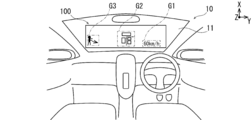
- FIG. 1 is a diagram schematically illustrating an example of a method for using the fluorescent light emitting display 100.
- the fluorescent light emitting display 100 is used by being attached to the indoor side of the windshield 11 of the vehicle 10.
- the fluorescent light emitting display 100 can display, for example, information on the speed of the vehicle 10 by characters (G1 in FIG. 1).
- the fluorescent display 100 can display information on the route from the current location of the vehicle 10 to the destination on a map (G2 in FIG. 1).
- the fluorescent light emitting display 100 can display information such as a pedestrian existing in the traveling direction of the vehicle 10 in a human figure (G3 in FIG. 1).
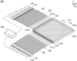
- FIG. 2 is a perspective view schematically showing the configuration of the fluorescent light emitting display 100 of FIG.
- a fluorescent light emitting display 100 (corresponding to a display device) according to the embodiment is briefly described.
- a display film 112 (corresponding to a display medium), a first light source 121, and a plurality of first light sources 121.
- One propagation member including the first optical fiber 122), a second light source 131, a plurality of second propagation members (including the second optical fiber 132), and a control unit 140 (corresponding to the control member) And).
- the display film 112 is excited by a plurality of excitation lights including the first excitation light EL11 (light having a wavelength of 1550 nm that is infrared light) and the second excitation light EL12 (light having a wavelength of 850 nm that is infrared light).
- the phosphor fine particles 111 (corresponding to the first light emitter) emitting the first fluorescence RL1 (green which is visible light) having a shorter wavelength than the plurality of excitation lights are dispersed and held, and the first fluorescence RL1 is displayed.
- the first light source 121 emits the first excitation light EL11.
- the first optical fiber 122 propagates the first excitation light EL11 from the first end surface 112c (corresponding to the first incident surface) of the display film 112 to the inside (FIG. 3).
- the second light source 131 emits second excitation light EL12.
- the second optical fiber 132 propagates the second excitation light EL12 from the second end face 112d (corresponding to the second incident surface) of the display film 112 to the inside so as to intersect the first excitation light EL11 ( FIG. 3).
- the control unit 140 controls the first light source 121 and the second light source 131 so that the first excitation light EL11 and the second excitation light EL12 intersect at a specific position of the display film 112.
- at least the first light source 121 is disposed away from the display film 112.
- the fluorescent light emitting display 100 will be described in detail.
- the fluorescent light-emitting display 100 includes a display unit 110 that displays information using green first fluorescent light RL1 that is visible light, and a first excitation light EL11 that supplies infrared light to the display unit 110.
- the light source unit 120 includes a second light source unit 130 that supplies the second excitation light EL12 of infrared light to the display unit 110, and a control unit 140 that controls the first light source unit 120 and the second light source unit 130.
- the display film 112 is exaggerated in the Z direction with respect to the X direction and the Y direction. That is, the display film 112 is originally formed in a sheet shape, but is shown exaggerated thickly. In FIG. 2, the display film 112 is illustrated as a square shape as an example. However, when the display film 112 is used by being attached to the entire surface of the windshield 11 of the vehicle 10 as illustrated in FIG. You may make it.
- display unit 110 includes a display film 112 that holds phosphor fine particles 111 uniformly and densely dispersed.
- Table 1 shows the optical characteristics of the phosphor fine particles 111.
- the phosphor fine particles 111 are fine particles that emit green first fluorescence RL1 that is visible light when excited by the first excitation light EL11 and the second excitation light EL12 that are infrared light, respectively.
- the phosphor fine particles 111 do not emit fluorescence only by the first excitation light EL11 or the second excitation light EL12.
- the phosphor fine particles 111 are configured by doping erbium (Er) as a light emitting material with respect to sodium yttrium fluoride (NaYF 4 ) as a base material halide, for example.
- Er erbium
- NaYF 4 sodium yttrium fluoride
- the first fluorescence corresponding to the light of the green wavelength is accompanied by the transition from the energy level of the Er 3+ ion. Issue RL1.
- the size of the phosphor fine particles 111 is sufficiently smaller than the spot diameters of the first excitation light EL11 and the second excitation light EL12 propagating through the display film 112.
- the wavelength of the first fluorescence RL1 emitted from the phosphor fine particles 111 depends on the type of the light emitting material doped into the base material.
- the display film 112 includes a first display surface 112a and a second display surface 112b facing each other.
- the first display surface 112a or the second display surface 112b displays various information (G1, G2, and G3 in FIG. 1) by the first fluorescence RL1.
- the display film 112 allows the first excitation light EL11 to enter from the first end surface 112c (the thickness portion of the display film 112) between the first display surface 112a and the second display surface 112b.
- the display film 112 receives the second excitation light EL12 from the second end surface 112d (thickness portion of the display film 112) between the first display surface 112a and the second display surface 112b and adjacent to the first end surface 112c. Make it incident.
- the display film 112 has a first end surface 112c that is sufficiently smaller than the first display surface 112a and is formed in a film shape.
- the display film 112 is made of a transparent material in the entire visible light range (purple to red). Therefore, in a state where the display film 112 is attached to the windshield 11 of the vehicle 10, an occupant of the vehicle 10 can visually recognize the front of the vehicle 10 through the display film 112.
- the first fluorescence RL1 emitted from the phosphor fine particles 111 in the display film 112 is green which is visible light.
- the peak of human visibility is about 555 nm in a bright place and about 507 nm in a dark place. Since the first fluorescence RL1 is green light corresponding to a wavelength of 500 nm to 560 nm, it is very easy for the passenger to visually recognize.
- the 1st excitation light EL11 and 2nd excitation light EL12 which propagate the display film 112 are infrared light, a passenger
- the first light source unit 120 includes a first light source 121 that emits first excitation light EL11, a plurality of first optical fibers 122 that propagate the first excitation light EL11 to the display film 112, A first collimator lens 123 that propagates the first excitation light EL11 incident from the first optical fiber 122 to the display film 112 while collimating, and an electric wire 124 that relays between the first light source 121 and the control unit 140 are included. Yes.
- the first light source 121 is configured by, for example, unitizing a laser diode that emits light corresponding to the wavelength of the first excitation light EL11 and a condensing lens that condenses the first excitation light EL11.
- the first light source 121 is constituted by an infrared light source of a CAN (metal tube with a window) package in which a laser diode having an oscillation wavelength of 1550 nm is mounted and a window plate is a condenser lens. ing.
- the laser diode of the first light source 121 for example, an infrared laser diode for optical communication is used. Infrared lasers for optical communication are generally reliable for light oscillation, robust and inexpensive.
- the condensing lens which is a window plate of the CAN package, condenses the first excitation light EL 11 emitted from the light source and makes it incident on the first optical fiber 122. Since the first light source 121 propagates the first excitation light EL11 through the first optical fiber 122, the first light source 121 can be separated from the display film 112 and disposed at an arbitrary place.
- the first optical fiber 122 propagates the first excitation light EL11 toward the display film 112.
- a single mode optical fiber (SMF) for optical communication corresponding to a wavelength of 1550 nm is used for the first optical fiber 122.
- Optical fibers for optical communication are generally reliable in light propagation, robust and inexpensive.
- the first optical fiber 122 has a numerical aperture (NA) representing the maximum light receiving angle of incident light, for example, 0.1 or less.
- the first collimator lens 123 collimates the first excitation light EL11 emitted from the first optical fiber 122.
- the first collimator lenses 123 are arranged in a line along the long and thin first end surface 112 c of the display film 112.
- the first collimator lens 123 is composed of an aspheric lens or a spherical lens.
- the first collimator lens 123 has a divergence angle and wavelength of the first excitation light EL11 emitted from the first optical fiber 122, a spot diameter of the first excitation light EL11 to be propagated to the display film 112, and the like. Determine the specifications.
- the specifications of the first collimator lens 123 relate to the material, the curvature of the entrance surface and the exit surface, and the working distance between the entrance surface of the first collimator lens 123 and the first optical fiber 122.
- the first collimator lens 123 may be constituted by a single array lens in which a plurality of collimator lenses are integrally formed. If one array lens is used, it is not necessary to arrange a plurality of collimator lenses with high accuracy, and it is easy to form each collimator lens in a dense manner.
- the electric wire 124 supplies electric power to the first light source 121 via the control unit 140.
- As the electric wire 124 a wire that satisfies the specifications of the drive current and drive voltage of the first light source 121 is selected and used.
- the second light source unit 130 intersects the first excitation light EL11 with the second light source 131 that emits light corresponding to the wavelength of the second excitation light EL12, and the second excitation light EL12.
- a plurality of second optical fibers 132 propagating to the display film 112
- a second collimator lens 133 propagating to the display film 112 while collimating the second excitation light EL12 incident from the second optical fiber 132
- An electric wire 134 that relays between the second light source 131 and the control unit 140 is included.
- the second light source 131 has the same configuration as that of the first light source 121 except that an infrared laser diode for optical communication having an oscillation wavelength corresponding to the second excitation light EL12 is 850 nm.
- the second light source 131 is separated from the display film 112 and disposed at an arbitrary location.
- the second optical fiber 132 propagates the second excitation light EL12 toward the display film 112.
- the second optical fiber 132 has the same configuration as that of the first optical fiber 122 except that, for example, an SMF for optical communication corresponding to a wavelength of 850 nm is used.
- the second collimator lens 133 has the same configuration as that of the first collimator lens 123 except that it corresponds to excitation light having a wavelength of 850 nm corresponding to the second excitation light EL12.
- the second collimator lenses 133 are arranged in a line along the elongated second end face 112d of the display film 112 so as to intersect with the first collimator lens 123.
- the electric wire 134 supplies electric power to the second light source 131 via the control unit 140.
- the electric wire 134 has the same configuration as the electric wire 124.
- control unit 140 controls the first light source 121 and the second light source 131.
- the control unit 140 includes a CPU (Central Processing Unit), a ROM (Read Only Memory), and a RAM (Random Access Memory).
- the CPU executes a control program related to the fluorescent light emitting display 100.
- the ROM stores a program.
- the program controls the light emission timing of the first light source 121 and the second light source 131 based on, for example, information related to display received from an external device.
- the external device is, for example, a control device that controls the vehicle 10, a wireless device provided in the car navigation system of the vehicle 10, and a camera device that is mounted on the vehicle 10 and recognizes a pedestrian or the like.
- the RAM temporarily stores the results of calculations executed by the CPU.
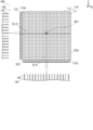
- FIG. 3 is a front view schematically showing a display method of the fluorescent light emitting display 100 of FIG.
- the fluorescent light emitting display 100 is propagated by the first excitation light EL ⁇ b> 11 propagated by the first optical fiber 122 and the second optical fiber 132 at a specific position of the display film 112.
- the second excitation light EL12 is crossed.
- the phosphor fine particles 111 present at the intersection of the first excitation light EL11 and the second excitation light EL12 emit the first fluorescence RL1 and display predetermined information.
- the phosphor fine particles 111 do not emit light when irradiated only with the first excitation light EL11 or the second excitation light EL12, but emit light when irradiated with both the first excitation light EL11 and the second excitation light EL12.
- the control unit 140 is configured to provide various information by the first optical fibers 122 arranged in a row and the second optical fibers 132 arranged in a row so as to intersect the first optical fibers 122. (G1, G2 and G3 in FIG. 1) are displayed. That is, the control unit 140 displays information including characters, figures, and the like by causing predetermined display pixels to simultaneously emit light among the display pixels present in a grid pattern on the display film 112.
- the first light source 121 is disposed apart from the display film 112, and the first propagation member propagates the first excitation light EL11 from the first end face 112c of the display film 112 to the inside.
- the optical fiber 122 is included.
- the second light source 131 is disposed apart from the display film 112, and the second propagation member propagates the second excitation light EL12 from the second end face 112d of the display film 112 to the inside.
- a second optical fiber 132 is included.
- the first excitation light EL11 is controlled to be propagated to the display film 112 through the first propagation member including the plurality of first optical fibers 122 to display information.
- the second excitation light EL12 is controlled to be propagated to the display film 112 through the second propagation member including the plurality of second optical fibers 132 to display information.
- an optical fiber (the first optical fiber 122 and the second optical fiber) is provided between the light source (the first light source 121 and the second light source 131) and the display film 112. Since the optical fiber 132) is provided, the degree of freedom in the layout of the light source with respect to the display film 112 can be increased.
- the optical fiber has been widely used in the field of optical communication, but has not been used in the field of a display device such as a fluorescent display.
- Conventional fluorescent light-emitting devices generate fluorescence while scanning laser light emitted from one laser light source in a plane with respect to a display medium, and display information by the fluorescence. That is, the conventional fluorescent light emitting devices have no configuration itself that generates fluorescence by crossing excitation lights emitted from a plurality of optical fibers in a lattice shape in a display medium.
- the fluorescent light emitting display 100 includes a plurality of first propagation members and a plurality of second propagation members, the first excitation light EL11 and the second excitation light EL12 may be crossed in a lattice pattern. Is possible. Accordingly, the fluorescent light emitting display 100 selectively propagates the first excitation light EL11 and the second excitation light EL12 to the display film 112, and simultaneously transmits the first fluorescence RL1 in a plurality of pixels of the display film 112. Information can be displayed. Therefore, the fluorescent light emitting display 100 can sufficiently enhance the responsiveness of information displayed on the display film 112 by causing a plurality of pixels to emit light simultaneously.
- the fluorescent light emitting display 100 uses an optical fiber that hardly generates heat as an optical member for propagating the first excitation light EL11. Therefore, the fluorescent light emitting display 100 can be arranged so that the optical fibers are closely packed so as to be adjacent to each other, for example. Therefore, the fluorescent display 100 can sufficiently increase the resolution of information displayed on the display film 112. It should be noted that a configuration in which laser light sources are concentrated without using an optical fiber is realistic because the laser light sources are overheated, resulting in oscillation failure, and wiring (wire bonded power lines) becomes too dense. is not.
- the fluorescent light emitting display 100 hardly heats the display film 112 by the first optical fiber 122. Therefore, the fluorescent light emitting display 100 prevents the display film 112 from being deteriorated by heating to deteriorate optical characteristics, or the display film 112 from being deformed by heating to reduce the incident efficiency of the first excitation light EL11. it can.
- the fluorescent light emitting display 100 has a relatively small aperture diameter (for example, a core diameter of 100 ⁇ m and a fiber diameter including a clad of 120 ⁇ m) as a known optical member for the optical member that propagates the first excitation light EL11. )
- the configured optical fiber is used. Therefore, the fluorescent light emitting display 100 displays on the display film 112 by densely arranging the first optical fibers 122 along the incident surface (for example, the first end surface 112c) of the first excitation light EL11 of the display film 112. The resolution of information to be improved can be improved.
- the fluorescent light emitting display 100 uses an optical fiber that has very high light propagation efficiency and does not block light in the propagation path, as the optical member that propagates the first excitation light EL11. Therefore, the fluorescent light emitting display 100 can cause the display film 112 to stably display information by sufficiently propagating the first excitation light EL11 emitted from the first light source 121 to the display film 112.
- the fluorescent light emitting display 100 uses an optical fiber that can regulate the NA below a certain value as an optical member for propagating the first excitation light EL11. That is, the fluorescent light emitting display 100 can keep the spread angle of the first excitation light EL11 emitted from the first optical fiber 122 and incident on the display film 112 sufficiently shallow. Therefore, the fluorescent light emitting display 100 can maintain the rate of change of the beam shape with respect to the propagation direction of the first excitation light EL11 within a certain value, so that the size of the display pixel in the display film 112 is maintained within a predetermined range. can do.
- the exit surface of the first optical fiber 122 intersects the display surface (the first display surface 112a or the second display surface 112b) on which the first fluorescence RL1 of the display film 112 is displayed. It is preferable to face the one end face 112c.
- the first excitation light EL11 is propagated from the first end face 112c of the display film 112 to the inside. Therefore, the fluorescent light emitting display 100 can be placed at an arbitrary position without causing the first optical fiber 122 or the first light source 121 to interfere with the display surface (the first display surface 112a or the second display surface 112b) of the display film 112. Easy to place.
- the first excitation light EL11 enters the inside from the first end surface 112c of the display film 112, and then the display surfaces (the first display surface 112a and the second display surface 112b) facing the display medium. ) And sufficiently propagates from the first end face 112c toward the distal side. Therefore, the fluorescent light emitting display 100 can sufficiently secure the area of the display film 112 (the first display surface 112a and the second display surface 112b). That is, the display film 112 functions as an optical fiber formed in a film shape, and can propagate the first excitation light EL11.
- the first excitation light EL11 is displayed on the display surfaces (the first display surface 112a and the second display surface 112b) facing the curved display medium. Therefore, it is possible to display information appropriately.
- the fluorescent light emitting display 100 uses a first optical fiber 122 having a relatively small aperture diameter as a known optical member as an optical member for propagating the first excitation light EL11. Therefore, the fluorescent light emitting display 100 has the first end surface 112c even on the display film 112 configured to be a thin film as compared with the display surface (the first display surface 112a or the second display surface 112b).
- the first excitation light EL11 can be made sufficiently incident from the first end face 112c.
- the second optical fiber 132 has a second end face that intersects the display surface (the first display surface 112a or the second display surface 112b) of the display film 112 that displays the second fluorescent light RL2.
- the second excitation light EL12 is propagated toward 112d. Therefore, the fluorescent light emitting display 100 has the same effect as the first optical fiber 122 described above also in the second optical fiber 132.
- the fluorescent light emitting display 100 it is preferable to have the first collimator lens 123 between the emission surface of the first optical fiber 122 and the display film 112.
- the size of the display pixel on the display film 112 is set to the propagation of the first excitation light EL11. Can be constant along the direction. That is, the beam shape of the first excitation light EL11 is the same in a region close to the first end surface 112c and a region separated from the first end surface 112c. Therefore, the fluorescent light emitting display can make the size of the display pixels on the display film 112 uniform without depending on the position of the display film 112.
- the fluorescent light emitting display 100 has a second collimator lens 133 between the second optical fiber 132 and the display film 112. Therefore, the fluorescent light emitting display 100 has the same effect as the first collimator lens 123 described above also in the second collimator lens 133.
- the first light source 121 includes a plurality of second light sources 131
- the control unit 140 includes a specific first light source 121 corresponding to a specific position of the display film 112. And the second light source 131 is controlled.
- the fluorescent light emitting display 100 information is displayed by generating fluorescence while crossing the first excitation light EL11 and the second excitation light EL12 at a specific position of the display film 112 with a very simple configuration. be able to.
- the display film 112 can be attached to the windshield 11 of the vehicle 10 and used.
- the driver of the vehicle 10 confirms various information (G1, G2, and G3 in FIG. 1) displayed on the display film 112 while sufficiently viewing the front of the vehicle 10. can do.
- the fluorescent light emitting display 100 causes the first excitation light EL11 to propagate to the display film 112 via the plurality of first optical fibers 122, and the second excitation light EL12 is transmitted to the plurality of second excitation light EL12.
- the first excitation light EL11 is configured to propagate to the display film 112 via the plurality of first optical fibers 122, at least the degree of freedom of the layout of the first light source 121 with respect to the display film 112 is increased. Can do.
- the second light source 131 may be disposed close to the display film 112 without using the second optical fiber 132.
- the control method of the fluorescent light emitting display 100 is controlled such that the first excitation light EL11 is propagated to the display film 112 via the plurality of first optical fibers 122 to display information, and the first The two excitation lights EL12 have been described as being controlled to be propagated to the display film 112 via the plurality of second optical fibers 132 to display information, but the present invention is not limited to such a structure. If the first excitation light EL11 is controlled to propagate to the display film 112 via the plurality of first optical fibers 122, at least the freedom of the layout of the first light source 121 with respect to the display film 112 The degree can be increased.
- the second light source 131 displays the information by propagating the second excitation light EL12 to the display film 112 via the plurality of second optical fibers 132 if the arrangement with respect to the display film 112 is not limited. There is no need to control.
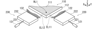
- FIG. 4 is a perspective view schematically showing a main part of the fluorescent light-emitting display according to Modification 1 of the embodiment.
- the fluorescent light-emitting display according to the first modification of the embodiment is different from the fluorescent light-emitting display 100 according to the above-described embodiment in that the number of the first light sources 121 and the second light sources 131 is reduced.
- the first light source unit 220 includes a light distributor 222 that branches the first excitation light EL11 in addition to the configuration of the first light source unit 120 described above.
- One first light source 121 is connected to one optical fiber 221 for light distribution.
- the light distribution optical fiber 221 has the same configuration as that of the first optical fiber 122, but is shorter than the first optical fiber 122.
- the emission side of the light distribution optical fiber 221 is connected to the light distributor 222.
- the light distributor 222 selectively propagates to the plurality of first optical fibers 122 while branching the first excitation light EL11 incident from the light distribution optical fiber 221. That is, the light distributor 222 propagates the first excitation light EL11 independently to the plurality of first optical fibers 122 based on the control of the control unit 140.
- the first excitation light EL11 emitted from the plurality of first optical fibers 122 is incident on each corresponding first collimator lens 123.
- the light distributor 222 is made up of, for example, a so-called MEMS (Micro Electronic Mechanical Systems: MEMS).
- MEMS Micro Electronic Mechanical Systems
- the light distributor 222 includes a small mirror, and selectively propagates the first excitation light EL11 emitted from the light distribution optical fiber 221 to the plurality of first optical fibers 122.
- the light distributor 222 causes the first excitation light EL11 emitted from the light distribution optical fiber 221 to propagate simultaneously to the plurality of first optical fibers 122 while branching a plurality of times by a so-called waveguide. It may be configured.
- the light distributor 222 is provided with an optical shutter for each of the plurality of first optical fibers 122 to selectively pass the first excitation light EL11.
- the shutter is composed of, for example, a liquid crystal element that functions as an optical switch.
- the second light source unit 230 includes a light distributor 232 for branching the second excitation light EL12 in addition to the configuration of the second light source unit 130 described above.
- One second light source 131 is connected to one optical fiber 231 for light distribution.
- the light distribution optical fiber 231 has the same configuration as that of the second optical fiber 132, but is shorter than the second optical fiber 132.
- the exit side of the light distribution optical fiber 231 is connected to the light distributor 232.
- the light distributor 232 selectively propagates to the plurality of second optical fibers 132 while branching the second excitation light EL12 incident from the light distribution optical fiber 231.
- the light distributor 232 has the same configuration as that of the light distributor 222 except that it corresponds to pump light having a wavelength of 850 nm corresponding to the second pump light EL12.
- the fluorescent light-emitting display has a light distributor 222 that branches the first excitation light EL11 and makes it incident on the plurality of first optical fibers 122.
- the number of the first light sources 121 can be reduced as compared with the case where a plurality of the first light sources 121 are provided corresponding to the plurality of first optical fibers 122. Therefore, the fluorescence display further improves the degree of freedom of arrangement of the first light source 121 with respect to the display film 112. Therefore, the fluorescence display can further increase the degree of layout freedom.
- the fluorescent light emitting display can suppress variations in optical characteristics due to individual differences of the first light sources 121, as compared with the case where a plurality of the first light sources 121 are provided.
- the individual difference of the first light source 121 is, for example, the light intensity of the first excitation light EL11. Therefore, the fluorescent light emitting display can make the optical characteristics such as brightness in the display film 112 uniform.
- the fluorescent light emitting display can be easily replaced with the aging deterioration of the first light source 121 as compared with the case where a plurality of the first light sources 121 are provided. Therefore, the fluorescent light emitting display can reduce the labor required for maintenance.
- the fluorescent light emitting display can reduce the space for housing the first light source 121 as compared with the case where a plurality of the first light sources 121 are provided. Therefore, the fluorescent light emitting display can be miniaturized.
- the fluorescent light emitting display can reduce the cost required for the first light source 121 as compared with the case where a plurality of the first light sources 121 are provided. Therefore, the fluorescent light emitting display can be constructed at a low cost.
- the fluorescent light-emitting display may have a configuration in which one light distribution optical fiber 221 is provided regardless of the number of the first optical fibers 122, or every certain number (for example, 10) of the first optical fibers 122.
- the light distribution optical fibers 221 may be provided one by one.
- the fluorescent light-emitting display includes a light distributor 232 that divides the second excitation light EL12 to enter the plurality of second optical fibers 132. Therefore, the fluorescent light emitting display has the same effect as that of the above-described light distributor 222 even in the light distributor 232 that divides the second excitation light EL12 and enters the plurality of second optical fibers 132.
- FIG. 5 is a perspective view schematically showing a main part of the fluorescent light emitting display according to the second modification of the embodiment.
- the fluorescent light-emitting display according to the second modification of the embodiment is different from the fluorescent light-emitting display 100 according to the above-described embodiment in that information is displayed in full color.
- the fluorescent light emitting display according to the second modification of the embodiment is a “one form” that embodies a configuration for displaying information in full color.
- the display film 112 has two or more other light emitters (phosphor fine particles 311 and phosphor fine particles 312) that emit other fluorescent light (red and blue) having a wavelength different from that of the fluorescent light (green). ) Is further dispersed and held.
- red, green and blue phosphor particles 111 emits green fluorescence
- phosphor fine particles 311 emits red fluorescence
- phosphor fine particles 312 emits blue fluorescence. Fluorescence of light of wavelength.
- the second light emitter (phosphor fine particle 311) that emits the second fluorescence RL2.
- a third light emitter (phosphor fine particles 312) that emits the third fluorescence RL3 when excited by the fifth excitation light EL31 and the sixth excitation light EL32 are further dispersed and held.
- the first fluorescence RL1, the second fluorescence RL2, and the third fluorescence RL3 are a combination of red, green, and blue wavelengths of light.
- the fluorescent light emitting display includes a third light source 321 that emits third excitation light EL21, a fourth light source 331 that emits fourth excitation light EL22, a fifth light source 323 that emits fifth excitation light EL31, And a sixth light source 333 that emits sixth excitation light EL32.
- the plurality of first optical fibers 328 propagate the first excitation light EL11, the third excitation light EL21, and the fifth excitation light EL31 toward the display film 112.
- the plurality of second optical fibers 338 propagate the second excitation light EL12, the fourth excitation light EL22, and the sixth excitation light EL32 toward the display film 112.
- display film 112 holds phosphor fine particles 311 and phosphor fine particles 312 uniformly and densely dispersed in addition to phosphor fine particles 111.
- Table 2 shows the optical characteristics of the phosphor fine particles 311 and the phosphor fine particles 312 in addition to the phosphor fine particles 111.
- the phosphor fine particles 311 are constituted by doping the base material NaYF 4 with praseodymium (Pr) as a light emitting material.
- Pr praseodymium
- the phosphor fine particles 311 are excited by the third excitation light EL21 (infrared light having a wavelength of 1014 nm) and the fourth excitation light EL22 (infrared light having a wavelength of 840 nm), Pr 3+ ions
- the red second fluorescence RL2 that is visible light is emitted in accordance with the transition from the energy level.
- the phosphor fine particles 311 do not emit fluorescence only by the third excitation light EL21 or the fourth excitation light EL22.
- the phosphor fine particles 312 are configured by doping the base material NaYF 4 with thulium (Tm) as the light emitting material.
- Tm thulium
- the phosphor fine particles 312 are excited by the fifth excitation light EL31 (infrared light having a wavelength of 800 nm) and the sixth excitation light EL32 (infrared light having a wavelength of 1120 nm), Tm 3+ ions
- the blue third fluorescence RL3 which is visible light, is emitted along with the transition from the energy level.
- the phosphor fine particles 312 do not emit fluorescence only by the fifth excitation light EL31 or the sixth excitation light EL32.
- the first light source unit 320 includes a third light source 321 and a fifth light source 323 in addition to the configuration of the first light source unit 220 described above.
- the third light source 321 emits third excitation light EL21.
- the third light source 321 has the same configuration as that of the first light source 121 except for the specification of the optical element related to the oscillation wavelength.
- the third light source 321 propagates the third excitation light EL21 to the light distribution optical fiber 322 suitable for the wavelength.
- the fifth light source 323 emits the fifth excitation light EL31.
- the fifth light source 323 has the same configuration as that of the first light source 121 except for the specification of the optical element related to the oscillation wavelength.
- the fifth light source 323 propagates the fifth excitation light EL31 to the light distribution optical fiber 324 suitable for the wavelength.
- the timing of light emission of the first light source 121, the third light source 321, and the fifth light source 323 is controlled by the control unit 140.
- the multiplexer 325 is configured, for example, by heating and melting the outgoing portions of the light distribution optical fiber 221, the light distribution optical fiber 322, and the light distribution optical fiber 324 while stretching them.
- the multiplexer 325 includes the pumping light (the first pumping light EL11, the third pumping light EL21, and the first pumping light emitted from the light distributing optical fiber 221, the light distributing optical fiber 322, and the light distributing optical fiber 324, respectively. 5 excitation lights EL31).
- the relay optical fiber 326 propagates each excitation light combined by the multiplexer 325 to the light distributor 327.
- the relay optical fiber 326 corresponds to each excitation light.
- the light distributor 327 selectively propagates the plurality of first optical fibers 328 while branching each excitation light propagated from the relay optical fiber 326.
- the light distributor 327 has the same specifications as the light distributor 222 described above, but has a configuration corresponding to each excitation light.
- the plurality of first optical fibers 328 propagate the first excitation light EL11, the third excitation light EL21, and the fifth excitation light EL31 toward the display film 112, respectively.
- the second light source unit 330 includes a fourth light source 331, a sixth light source 333 and the like in addition to the second light source unit 230 described above.
- the fourth light source 331 emits the fourth excitation light EL22.
- the fourth light source 331 has the same configuration as the second light source 131 except for the specifications of the optical element related to the oscillation wavelength.
- the fourth light source 331 propagates the fourth excitation light EL22 to the light distribution optical fiber 332.
- the sixth light source 333 emits sixth excitation light EL32.
- the sixth light source 333 has the same configuration as the second light source 131 except for the specifications of the optical element related to the oscillation wavelength.
- the sixth light source 333 propagates the sixth excitation light EL32 to the light distribution optical fiber 334.
- the timing of light emission of the second light source 131, the fourth light source 331, and the sixth light source 333 is controlled by the control unit 140.
- the multiplexer 335 is formed by, for example, heating and melting the light emitting portions of the light distribution optical fiber 231, the light distribution optical fiber 332, and the light distribution optical fiber 334 while stretching them.
- the multiplexer 335 includes each of the pumping light (second pumping light EL12, fourth pumping light EL22, and second pumping light emitted from the light distributing optical fiber 231, the light distributing optical fiber 332, and the light distributing optical fiber 334. 6 excitation lights EL32).
- the relay optical fiber 336 propagates each pump light combined by the multiplexer 335 to the light distributor 337.
- the relay optical fiber 336 corresponds to each excitation light.
- the light distributor 337 selectively propagates the plurality of second optical fibers 338 while branching each pumping light propagated from the relay optical fiber 336.
- the light distributor 337 has the same specifications as the light distributor 232 described above, but has a configuration corresponding to each excitation light.
- the plurality of second optical fibers 338 propagate the second excitation light EL12, the fourth excitation light EL22, and the sixth excitation light EL32 toward the display film 112, respectively.
- the display film 112 has two or more other light emitters (phosphor fine particles 311 and phosphor fine particles 312) that emit other fluorescent light (red and blue) having a wavelength different from that of the fluorescent light (green). ) Is further dispersed and held.
- the fluorescent fine particles 111 emits green fluorescence
- the phosphor fine particles 311 emits red fluorescence
- the phosphor fine particles 312 emits blue fluorescence
- information to be displayed on the display film 112 can be expressed by so-called full color from purple to red by mixing three colors of red, green and blue. Therefore, the fluorescent display can display more information.
- the fluorescent light emitting display it is preferable to have a multiplexer 325.
- the multiplexer 325 combines the first excitation light EL11, the third excitation light EL21, and the fifth excitation light EL31 (via the relay optical fiber 326 and the light distributor 327) to generate the first light.
- the light enters the fiber 328.
- the number of optical fibers can be reduced as compared with the case of providing three types of optical fibers corresponding to excitation light of three types of wavelengths. Therefore, the fluorescent light-emitting display can reduce the space required for the optical fiber, and can further improve the degree of freedom of arrangement of the first light source 121 and the like with respect to the display film 112.
- the fluorescent light-emitting display uses three first wavelengths of excitation light by one first optical fiber 328 as compared to the case where three types of wavelengths of excitation light propagate through three independent optical fibers. It can be propagated densely. That is, as compared with the case where three optical fibers that propagate red, green, and blue independently are used in a bundle, one optical fiber that propagates by combining red, green, and blue light is used. However, the size of one pixel can be reduced. Therefore, the up-conversion fluorescent display can further improve the resolution of the display film 112.
- the fluorescent light emitting display can be easily replaced with the aging deterioration of the first optical fiber 328 as compared with the case where three types of optical fibers are provided. Therefore, the fluorescent light emitting display can reduce the labor required for maintenance.
- the fluorescent light emitting display can reduce the space for housing the first optical fiber 328 as compared with the case where three types of optical fibers are provided. Therefore, the fluorescent light emitting display can be miniaturized.
- the fluorescent light emitting display can reduce the cost required for the first optical fiber 328 as compared with the case where three types of optical fibers are provided. Therefore, the fluorescent light emitting display can be constructed at a low cost.
- the fluorescent light emitting display combines the second excitation light EL12, the fourth excitation light EL22, and the sixth excitation light EL32 (via the relay optical fiber 336 and the light distributor 337).
- the optical coupler 335 is incident on the optical fiber 338. Therefore, the fluorescent light emitting display has the same effect as the above-described multiplexer 325 even in the multiplexer 335.
- FIG. 6 is a perspective view schematically showing a main part of a fluorescent light emitting display according to Modification 3 of the embodiment.
- the fluorescent light-emitting display according to Modification 3 of the embodiment is different from the fluorescent light-emitting display according to Modification 2 of the above-described embodiment in that information is displayed in full color by a combination of fewer phosphor fine particles and a light source. That is, in the third modification of the embodiment, two types of phosphor fine particles and four types of light sources are used. In Modification 2 of the above-described embodiment, three types of phosphor fine particles and six types of light sources are used.
- the fluorescent light-emitting display according to the third modification of the embodiment is an “other form” that embodies a configuration for displaying information in full color.
- the display film 112 further holds one or more other light emitters (one of the phosphor fine particles 312) that emit other fluorescence (blue) having a wavelength different from that of the fluorescence (green). is doing.
- fluorescent fine particles 111 emits red and green fluorescence
- phosphor fine particles 312 emits blue fluorescence
- the fluorescent light emitting display emits the fourth fluorescence RL4 (red) when the phosphor fine particles 111 are excited by the first excitation light EL11 and the seventh excitation light EL42.
- the display film 112 When the display film 112 is excited by the eighth excitation light EL51 and the seventh excitation light EL42, the display film 112 further disperses the fourth luminous body (phosphor fine particles 312) that emits the fifth fluorescence RL5 (blue). keeping.
- the first fluorescence RL1 (green), the fourth fluorescence RL4 (red), and the fifth fluorescence RL5 (blue) are composed of a combination of light of red, green, and blue wavelengths.
- the fluorescent light emitting display further includes a seventh light source 431 that emits seventh excitation light EL42 and an eighth light source 421 that emits eighth excitation light EL51.
- the plurality of first optical fibers 426 propagate the first pumping light EL11 and the eighth pumping light EL51 toward the display film 112, and the plurality of second optical fibers 436 includes the second pumping light EL11.
- the excitation light EL12 and the seventh excitation light EL42 are propagated toward the display film 112.
- display film 112 holds phosphor fine particles 312 uniformly and densely dispersed in addition to phosphor fine particles 111.
- Table 3 shows the optical characteristics of the phosphor fine particles 111 and the phosphor fine particles 312.
- the phosphor fine particles 111 described above are excited by the first excitation light EL11 (infrared light having a wavelength of 1550 nm) and the seventh excitation light EL42 (infrared light having a wavelength of 1120 nm), respectively. Along with the transition from the energy level of the Er 3+ ion, a fourth fluorescence RL4 corresponding to light having a red wavelength, which is visible light, is emitted. The phosphor fine particles 111 do not emit fluorescence only by the first excitation light EL11 or the seventh excitation light EL42.
- the phosphor fine particles 312 described above are excited by the eighth excitation light EL51 (infrared light having a wavelength of 800 nm) and the seventh excitation light EL42, the phosphor fine particles 312 are accompanied by a transition from the energy level of the Tm 3+ ion.
- the blue fifth fluorescence RL5 that is visible light is emitted.
- the phosphor fine particles 312 do not emit fluorescence only by the eighth excitation light EL51 or the seventh excitation light EL42.
- the first light source unit 420 includes an eighth light source 421 in addition to the configuration of the first light source unit 220 described above.
- the eighth light source 421 emits the above-described eighth excitation light EL51.
- the eighth light source 421 has the same configuration as that of the first light source 121 except for the specification of the optical element related to the oscillation wavelength.
- the eighth light source 421 propagates the eighth excitation light EL51 to the light distribution optical fiber 422 suitable for the wavelength.
- the timing of light emission of the first light source 121 and the eighth light source 421 is controlled by the control unit 140.
- the multiplexer 423 is configured, for example, by heating and melting the outgoing portions of the light distribution optical fiber 221 and the light distribution optical fiber 422 while stretching.
- the multiplexer 423 multiplexes the respective excitation lights (first excitation light EL11 and eighth excitation light EL51) emitted from the light distribution optical fiber 221 and the light distribution optical fiber 422.
- the relay optical fiber 424 propagates each pumping light multiplexed by the multiplexer 423 to the light distributor 425.
- the relay optical fiber 424 corresponds to each excitation light.
- the light distributor 425 selectively propagates the plurality of first optical fibers 426 while branching each pumping light propagated from the relay optical fiber 424.
- the light distributor 425 has the same specifications as the light distributor 222 described above, but has a configuration corresponding to each excitation light.
- the plurality of first optical fibers 426 propagate the first excitation light EL11 and the eighth excitation light EL51 toward the display film 112, respectively.
- the second light source unit 430 includes a seventh light source 431 and the like in addition to the configuration of the second light source unit 230 described above.
- the seventh light source 431 emits the seventh excitation light EL42 described above.
- the seventh light source 431 has the same configuration as the second light source 131 except for the specifications of the optical element related to the oscillation wavelength.
- the seventh light source 431 propagates the seventh excitation light EL42 to the light distribution optical fiber 432 suitable for the wavelength.
- the timing of light emission of the second light source 131 and the seventh light source 431 is controlled by the control unit 140.
- the multiplexer 433 is configured, for example, by heating and melting the outgoing portions of the light distribution optical fiber 231 and the light distribution optical fiber 432 while being melted.
- the multiplexer 433 multiplexes the respective excitation lights (second excitation light EL12 and seventh excitation light EL42) emitted from the light distribution optical fiber 231 and the light distribution optical fiber 432.
- the relay optical fiber 434 propagates each excitation light combined by the multiplexer 433 to the light distributor 435.
- the relay optical fiber 434 corresponds to each excitation light.
- the light distributor 435 selectively propagates the plurality of second optical fibers 436 while branching each pumping light propagated from the relay optical fiber 434.
- the light distributor 435 has the same specifications as the light distributor 232 described above, but has a configuration corresponding to each excitation light.
- the plurality of second optical fibers 436 propagate the second excitation light EL12 and the seventh excitation light EL42 toward the display film 112, respectively.
- the display film 112 further holds one or more other light emitters (one of the phosphor fine particles 312) that emit other fluorescence (blue) having a wavelength different from that of the fluorescence (green). is doing.
- the fluorescent fine particles 111 which emit red and green fluorescence
- the fluorescent fine particles 312 which emit blue fluorescence
- the fluorescent light emitting display can display a lot of information while further improving the degree of freedom of the arrangement of the light sources with respect to the display film 112 by reducing the types of light sources.
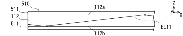
- FIG. 7 is a top view schematically showing the main part of the fluorescent light-emitting display according to Modification 4 of the embodiment.
- the fluorescent light-emitting display according to the modification 4 of the embodiment is the fluorescent light-emitting according to the above-described embodiment in that a transparent covering member 511 is attached to the display film 112 so that excitation light does not leak from the display film 112. Different from the display 100.
- the covering member 511 is formed in a film shape thinner than the display film 112.
- the covering member 511 is made of a material that is transparent in the entire visible light range (purple to red).
- the covering member 511 includes a first excitation light EL11, a second excitation light EL12, a third excitation light EL21, a fourth excitation light EL22, a fifth excitation light EL31, a sixth excitation light EL32, and a seventh excitation light EL11.
- the light having the wavelengths of the excitation light EL42 and the eighth excitation light EL51 is made of a material having a refractive index smaller than that of the display film 112.
- the covering member 511 is composed of a pair, for example, and is adhered to both surfaces of the display film 112.
- the display film 112 and the covering member 511 correspond to a relationship between a so-called optical fiber core and a clad (having a smaller refractive index than the core). That is, the first excitation light EL11 and the second excitation light EL12 are the interface between the first display surface 112a and the covering member 511 of the display film 112 and the second display surface 112b and the covering member 511 of the display film 112. It propagates inside the display film 112 while being reflected at the interface.
- Fluorescent light-emitting display has a covering member 511.
- the covering member 511 is in contact with the display film 112 and has a refractive index smaller than that of the display film 112 in the light of the wavelengths of the first excitation light EL11 and the second excitation light EL12.
- the first excitation light EL11 and the second excitation light EL12 propagating in the display film 112 are reflected at the interface between the display film 112 and the covering member 511, whereby the display film 112 is displayed. To the outside can be prevented. Therefore, the fluorescent light emitting display can appropriately display information on the display film 112. That is, the covering member 511 is a member that prevents the first excitation light EL11 and the second excitation light EL12 from being emitted to the outside by contacting the cover member 511 with an arbitrary surface of the display film 112. Can be used.
- the fluorescent light emitting display when the fluorescent light emitting display is provided with the covering member 511 on one side of the display film 112, the fluorescent light emitting display is attached to the windshield 11 so that the covering member 511 faces the windshield 11 side, for example. If comprised in this way, the 1st excitation light EL11 and 2nd excitation light EL12 which propagate the inside of the display film 112 will not enter into the windshield 11 from the display film 112, but the display film 112 and the coating
- the fluorescent light emitting display includes the covering members 511 on both surfaces of the display film 112, the covering member 511 can be opposed to the indoor side of the vehicle 10 in addition to the windshield 11 side. . If comprised in this way, the 1st excitation light EL11 and 2nd excitation light EL12 which propagate through the display film 112 will inject into the water drop and oil film which adhered to the coating
- FIG. 8A is a front view schematically showing a display method of the fluorescent light emitting display 600 according to the modified example 5-1 of the embodiment.
- FIG. 8B is a front view schematically showing a display method of the fluorescent light-emitting display 1600 according to the comparison 1 of the display method shown in FIG. 8A.
- FIG. 9 is a diagram illustrating a relationship between the excitation light irradiation time and the fluorescence intensity according to the modified example 5-1 of the embodiment.
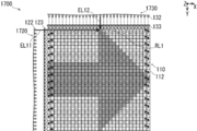
- FIG. 10A is a front view schematically showing a display method of the fluorescent light emitting display 700 according to the modification 5-2 of the embodiment.
- FIG. 10B is a front view schematically showing a display method of the fluorescent light-emitting display 1700 according to the proportional 2 of the display method shown in FIG. 10A.
- FIG. 11A is a front view schematically showing a display method of the fluorescent light-emitting display 800 according to Modification 5-3 of the embodiment.
- FIG. 11B is a front view schematically showing a display method of the fluorescent light-emitting display 1800 according to the comparison 3 of the display method shown in FIG. 11A.
- the fluorescent light-emitting displays 600, 700, and 800 according to the modified examples 5-1, 5-2, and 5-3 of the embodiment are different from the first excitation light EL11 only at a specific position where information (for example, an arrow) is displayed.
- An optical fiber (first optical fiber 122) that propagates the first excitation light EL11 and an optical fiber (second optical fiber) that propagates the second excitation light EL12 so that the second excitation light EL12 intersects. 132) is selectively used.
- the fluorescent light-emitting displays 600, 700, and 800 according to the modification examples 5-1, 5-2, and 5-3 of the embodiment use the first excitation light EL11 and the second excitation light by the vector scan method.
- the excitation light EL12 is scanned. This will be specifically described below.
- Table 4 shows the specifications of the fluorescent display 600 (FIG. 8A) according to the modified example 5-1 of the embodiment and the fluorescent display 1600 (FIG. 8B) according to the comparative example 1.
- the first light source unit 620 collimates the first excitation light EL11 emitted from the first optical fiber 122 by the first collimator lens 123, while Propagates to the display film 112.
- the second light source unit 630 propagates the second excitation light EL12 emitted from the second optical fiber 132 to the display film 112 while being collimated by the second collimator lens 133.
- the image displayable area in the display film 112 of the display unit 110 is 900 (vertical 30 ⁇ horizontal 30) pixels, respectively.
- Each frame of the fluorescent light emitting display 600 and the fluorescent light emitting display 1600 is composed of 900 pixels.
- Fluorescent light emitting display 600 and fluorescent light emitting display 1600 each display an image on the entire surface (900 pixels) of one frame. That is, the fluorescent display 600 and the fluorescent display 1600 have the same image displayable area and image display range.
- the fluorescent light emitting display 600 and the fluorescent light emitting display 1600 display information including arrows drawn out only at the outer edge.
- information consisting of arrows that are hollowed out only at the outer edge is displayed by causing a total of 88 pixels to fluoresce so as to form an arrow shape.
- the fluorescent light emitting display 600 In the vector scan type fluorescent light emitting display 600, only 88 pixels that emit fluorescent light are controlled to be irradiated with excitation light in one frame (900 pixels). In the vector scan method, scanning (irradiation) is performed while turning on a signal (excitation light) only for pixels that display information (fluoresce fluorescence) with respect to pixels included in the image displayable region. Therefore, the fluorescent light emitting display 600 can irradiate each of the 88 pixels that emit fluorescent light with excitation light for 11.4 msec (1 sec / 88 pixels) per second during one frame.
- a signal is sent to a pixel that displays information (fluoresces) and a pixel that does not display information (does not emit fluorescence). Scan (irradiate) while selectively turning on and off.
- the fluorescent light-emitting display 1600 irradiates the excitation light to 88 pixels that emit fluorescence (ON), stops the operation for the other 812 (900-88) pixels, and does not irradiate the excitation light (OFF). Therefore, the fluorescent light emitting display 1600 can irradiate excitation light only for 1.11 msec (1 sec / 900 pixels) per second in one frame to each of the 88 pixels that emit fluorescent light. .
- Table 5 shows the specifications of the fluorescent display 700 (FIG. 10A) according to the modified example 5-2 of the embodiment and the fluorescent display 1700 (FIG. 10B) according to the comparative example 2.
- the first light source unit 720 collimates the first excitation light EL11 emitted from the first optical fiber 122 by the first collimator lens 123, while the first light source unit 720 collimates the first excitation light EL11. Propagates to the display film 112.
- the second light source unit 730 propagates the second excitation light EL12 emitted from the second optical fiber 132 to the display film 112 while being collimated by the second collimator lens 133.
- the image displayable area in the display film 112 of the display unit 110 is 900 (vertical 30 ⁇ horizontal 30) pixels, respectively.
- Each frame of the fluorescent display 700 and the fluorescent display 1700 is composed of 900 pixels.
- Fluorescent light emitting display 700 and fluorescent light emitting display 1700 each display an image on the entire surface (900 pixels) of one frame. That is, the fluorescent display 700 and the fluorescent display 1700 have the same image displayable area and image display range.
- the fluorescent light emitting display 700 and the fluorescent light emitting display 1700 display information including arrows that are solid and not hollowed out.
- information consisting of solid and unbroken arrows is displayed with a total of 280 pixels fluoresced so as to form an arrow shape.
- control is performed so that only 280 pixels that emit fluorescent light are irradiated with excitation light in one frame (900 pixels). Therefore, the fluorescent light-emitting display 700 can irradiate excitation light for 3.57 msec (1 sec / 280 pixels) per second during one frame to each pixel of the 280 pixels that emit fluorescent light.
- the fluorescent light-emitting display 1700 control is performed so that excitation light is selectively irradiated to all 900 pixels in one frame (900 pixels) regardless of the necessity of fluorescent light emission.
- the fluorescent light-emitting display 1700 irradiates excitation light to 280 pixels that emit fluorescence (ON), and stops the operation of other 620 (900-280) pixels and does not irradiate excitation light (OFF). Accordingly, the fluorescent light-emitting display 1700 can irradiate the excitation light only for 1.11 msec (1 sec / 900 pixels) per second during one frame for each of the 280 pixels that emit fluorescent light. .
- Table 6 shows the specifications of the fluorescent light-emitting display 800 (FIG. 11A) according to the modified example 5-3 of the embodiment and the fluorescent light-emitting display 1800 (FIG. 11B) according to the comparative example 3.
- the first light source unit 820 collimates the first excitation light EL11 emitted from the first optical fiber 122 by the first collimator lens 123, while the display unit 810 Propagates to the display film 812.
- the second light source unit 830 propagates the second excitation light EL12 emitted from the second optical fiber 132 to the display film 812 while being collimated by the second collimator lens 133.
- the image displayable area in the display film 812 of the display unit 810 is each 14400 (vertical 60 ⁇ 240 horizontal) pixels.
- One frame of the fluorescent display 800 and the fluorescent display 1800 is composed of 14400 pixels.
- Fluorescent light emitting display 800 and fluorescent light emitting display 1800 each display an image on a part of one frame (900 pixels). That is, the fluorescent display 800 and the fluorescent display 1800 are not equal in image displayable area and image display range.
- the image display range is located, for example, at the end of the image displayable area.
- the image displayable area is 16 times the image display range.
- the fluorescent light emitting display 800 and the fluorescent light emitting display 1800 display information including arrows drawn out only at the outer edge.
- information consisting of arrows that are hollowed out only at the outer edge is displayed with a total of 88 pixels fluorescently emitted so as to form the shape of the arrows.
- control is performed so that only 88 pixels that emit fluorescent light are irradiated with excitation light in one frame (14400 pixels). Therefore, the fluorescent light-emitting display 800 can irradiate each of the 88 pixels that emit fluorescent light with excitation light for 11.4 msec (1 sec / 88 pixels) per second during one frame.
- the fluorescent light-emitting display 1800 In the raster scan type fluorescent light-emitting display 1800, control is performed so that excitation light is selectively irradiated to all 14400 pixels in one frame (14400 pixels) regardless of the necessity of fluorescent light emission.
- the fluorescent light-emitting display 1800 irradiates the excitation light to 88 pixels that emit fluorescence (ON), stops the operation of the other 14312 (14400-88) pixels, and does not irradiate the excitation light (OFF). Therefore, the fluorescent display 1800 emits excitation light only for 6.94 ⁇ 10 ⁇ 2 msec (1 sec / 14400 pixels) per second in one frame for each of the 88 pixels that emit fluorescence. Cannot irradiate.
- the control method of the display device is such that the first excitation light EL11 is propagated so that the first excitation light EL11 and the second excitation light EL12 intersect only at a specific position where information (for example, an arrow) is displayed.
- the first optical fiber 122 and the second optical fiber 132 that propagates the second excitation light EL12 are controlled to be selectively used.
- the display device control method is a control method using a so-called vector scan method. Compared with a control method using a so-called raster scan method, this display device control method irradiates a pixel that displays information (arrow) (fluorescent light emission) in an image displayable region with a longer excitation light. be able to. Increasing the irradiation time of excitation light per unit time in one pixel increases the luminance of fluorescence in that pixel when the light intensity of the excitation light is constant. Therefore, this control method of the display device can make information (an arrow represented by fluorescence) easily visible.
- the control method for such a display device displays information (arrows) as compared with the control method using the raster scan method when an image is displayed only in a part of the image displayable region (Modification 5-3).
- Excitation light can be irradiated to a pixel to be displayed (fluorescent light emitted) for a very long time. Therefore, this control method of the display device is more information (represented by fluorescence) than the control method using the raster scan method when an image is displayed only in a part of the image displayable region (Modification 5-3). Can be made very easy to visually recognize.
- such a control method of the display device makes it easy to visually recognize information (an arrow represented by fluorescence), and as an example, the display film (attached to the windshield 11) in a bright environment (at the time of sunny summer).
- the contrast can be kept sufficiently with respect to visible light (sunlight) that is transmitted through.
- the fluorescent light emitting display 100 uses an optical fiber capable of arbitrarily selecting the diameter of the core as an optical member for propagating the first excitation light EL11 and the second excitation light EL12. Therefore, the fluorescent light-emitting display 100 can arbitrarily set the beam shapes of the first excitation light EL11 and the second excitation light EL12 that enter the display film 112 by combining a plurality of types of optical fibers having different core diameters. Can do. For this reason, by selecting an optical fiber having a sufficiently small core diameter, it is possible to display information densely for a specific region of the display film 112 by reducing the display pixels and increasing the resolution. it can.
- the information displayed densely is expressed by numbers or letters, for example, and is information such as the speed of the vehicle 10.
- display pixels can be enlarged in other regions of the display film 112 to display information roughly.
- the information to be roughly displayed is information such as a pedestrian or the like that is represented by a human figure, for example, in the traveling direction of the vehicle 10.
- the display film 112 is formed in a plate shape or a film shape and the information is displayed in two dimensions.
- the present invention is not limited to such a configuration.
- the display film 112 is formed in a rectangular shape, and the information is displayed three-dimensionally by the first optical fibers 122 arranged in a lattice shape and the second optical fibers 132 arranged in a lattice shape. It is good.
- the first excitation light EL11 and the second excitation light EL12 have been described as being configured to enter the display film 112 from different surfaces.
- the present invention is not limited to such a configuration.
- the first excitation light EL11 and the second excitation light EL12 may be configured to enter the display film 112 from the same surface. That is, the first incident surface and the second incident surface may be configured from the same surface.
- the first excitation light EL11 and the second excitation light EL12 are obliquely incident on the surface of the display film 112 and intersect each other inside the display film 112.
- the fluorescent light emitting display has been described as a display device used in the vehicle 10, but is not limited to such a configuration.
- the fluorescent light-emitting display may be configured to display various information as a so-called television, or to be installed outdoors to display information on traffic and advertisement.
- the fluorescent light emitting display is described as being used by being attached to the windshield 11, but the present invention is not limited to such a configuration.
- it is good also as a structure which affixes and uses a fluorescent light emission display on the side surface facing the driver's seat of the dashboard of the vehicle 10.
- the propagation member includes, for example, collimator lenses (first collimator lens 123 and second collimator lens 133).
- collimator lenses first collimator lens 123 and second collimator lens 133.
- the fifth modification of the embodiment can be applied to the configurations of the first to fourth modifications of the embodiment.
- the excitation light is selectively applied to a plurality of optical fibers by the galvanomirror method or the MEMS (Micro Electro Mechanical Systems) method. To propagate.
Landscapes
- Physics & Mathematics (AREA)
- General Physics & Mathematics (AREA)
- Optics & Photonics (AREA)
- Engineering & Computer Science (AREA)
- Chemical & Material Sciences (AREA)
- Theoretical Computer Science (AREA)
- Microelectronics & Electronic Packaging (AREA)
- Inorganic Chemistry (AREA)
- Materials Engineering (AREA)
- Organic Chemistry (AREA)
- Electroluminescent Light Sources (AREA)
Abstract
表示媒体に対する光源のレイアウトの自由度を高めることができる表示装置を提供する。 蛍光発光ディスプレイ(100)の表示フィルム(112)は、第1の励起光(EL11)と第2の励起光(EL12)によって励起されると、その励起光よりも波長が短い第1の蛍光(RL1)を発する蛍光体微粒子(111)を分散させて保持し、第1の蛍光(RL1)を表示させる。第1の光源(121)は、第1の励起光(EL11)を発する。第1の伝搬部材は、第1の励起光(EL11)を表示フィルム(112)の第1の入射面(112c)から内部に伝搬する。第2の光源(131)は、第2の励起光(EL12)を発する。第2の伝搬部材は、第1の励起光(EL11)と交差させるように第2の励起光(EL12)を表示フィルム(112)の第2の入射面(112d)から内部に伝搬する。制御ユニット(140)は、第1の光源(121)と第2の光源(131)を制御する。第1の光源(121)は表示フィルム(112)から離間して配置し、第1の伝搬部材は第1の光ファイバ(122)を含む。
Description
本発明は、表示装置および表示装置の制御方法に関する。
従来から、2種類の波長の励起光によって励起されると当該励起光よりも波長が短い蛍光を発する発光体を分散させて保持した表示媒体を備え、蛍光によって所定の情報を表示させる表示装置がある(特許文献1を参照。)。
特許文献1に開示された表示装置では、表示媒体(表示部)の内部に向かって2種類の光源(赤外光源)からそれぞれ励起光(赤外光)を照射して、それらの励起光が交差した部分に存在する発光体(蛍光体粒子)から蛍光を発生させることによって、所定の情報を表示させている。
なお、表示装置に関連して、特開2006-249254号(特許第5050140号)、特開2002-540247号、特開2007-530716号、特開2008-266628号、特開2005-206393号、特開2005-206628号および特開2008-292661号に記載された技術が挙げられる。
ところで、光源を任意の位置に配置できれば、表示装置に対する光源のレイアウトが非常に容易になる。特許文献1に記載の表示装置や、その表示装置に関連した技術では、光源から発せられた励起光を表示媒体に対して直接的に入射していることから、光源を表示媒体に対向するようにして配置する必要がある。
このように、従来の構成の表示装置では、表示媒体に対して光源を任意の位置に配置することが困難である。したがって、表示媒体に対して光源を自由にレイアウトできる技術の開発が要請されている。
本発明は、上記の要請に応えるためになされたものであり、表示媒体に対する光源のレイアウトの自由度を高めることができる表示装置および表示装置の制御方法を提供することにある。
上記目的を達成するための本発明の表示装置は、表示媒体と、第1の光源と、複数の第1の伝搬部材と、第2の光源と、複数の第2の伝搬部材と、制御部材と、を有する。前記表示媒体は、第1の励起光と第2の励起光とを含む複数の励起光によって励起されると前記複数の励起光よりも波長が短い蛍光を発する発光体を分散させて保持し、前記蛍光を表示させる。前記第1の光源は、前記第1の励起光を発する。前記第1の伝搬部材は、前記第1の励起光を前記表示媒体の第1の入射面から内部に伝搬する。前記第2の光源は、前記第2の励起光を発する。前記第2の伝搬部材は、前記第1の励起光と交差させるように前記第2の励起光を前記表示媒体の第2の入射面から内部に伝搬する。前記制御部材は、前記表示媒体の特定の位置において前記第1の励起光と前記第2の励起光とを交差させるように前記第1の光源および前記第2の光源を制御する。ここで、少なくとも、前記第1の光源は、前記表示媒体から離間して配置し、前記第1の伝搬部材は光ファイバを含む。
上記目的を達成するための本発明の表示装置の制御方法は、第1の励起光と第2の励起光とを含む複数の励起光によって励起されると前記複数の励起光よりも波長が短い蛍光を発する発光体を分散させて保持し前記蛍光を表示させる表示媒体に対して、前記第1の励起光と前記第2の励起光とをそれぞれ伝搬させつつ特定の位置において交差させて前記蛍光を発生させることによって情報を表示するように制御する。ここで、少なくとも、前記第1の励起光を複数の光ファイバを含む伝搬部材を介して前記表示媒体に対して伝搬させて前記情報を表示するように制御する。
以下、添付した図面を参照しながら、本発明の実施形態を説明する。図面において、同一の部材には同一の符号を付し、重複する説明を省略する。図面において、各部材の大きさや比率は、実施形態の理解を容易にするために誇張し、実際の大きさや比率とは異なる場合がある。
図において、X、Y、およびZによって表す矢印は、方向を示している。Xによって表す矢印は、表示フィルム112における第1の励起光EL11等の伝搬方向を示している。Yによって表す矢印は、Xによって表す方向と直交し、表示フィルム112における第2の励起光EL12等の伝搬方向を示している。Zによって表す矢印は、表示フィルム112の厚み方向を示している。
(実施形態)
図1は、蛍光発光ディスプレイ100の使用方法の一例を模式的に示す図である。
図1は、蛍光発光ディスプレイ100の使用方法の一例を模式的に示す図である。
図1を参照して、蛍光発光ディスプレイ100は、一例として、車両10のフロントガラス11の室内側に貼り付けて使用する。蛍光発光ディスプレイ100は、例えば、車両10の速度等に関する情報を文字によって表示することができる(図1中のG1)。蛍光発光ディスプレイ100は、車両10の現在地から目的地までの道順に関する情報を地図によって表示することができる(図1中のG2)。蛍光発光ディスプレイ100は、車両10の進行方向に存在する歩行者等の情報を人型の図形で表示することができる(図1中のG3)。
図2は、図1の蛍光発光ディスプレイ100の構成を模式的に示す斜視図である。
図2を参照して、実施形態に係る蛍光発光ディスプレイ100(表示装置に相当する)は、概説すれば、表示フィルム112(表示媒体に相当する)と、第1の光源121と、複数の第1の伝搬部材(第1の光ファイバ122を含む)と、第2の光源131と、複数の第2の伝搬部材(第2の光ファイバ132を含む)と、制御ユニット140(制御部材に相当する)と、を有する。表示フィルム112は、第1の励起光EL11(赤外光である波長1550nmの光)と第2の励起光EL12(赤外光である波長850nmの光)とを含む複数の励起光によって励起されると複数の励起光よりも波長が短い第1の蛍光RL1(可視光である緑色)を発する蛍光体微粒子111(第1の発光体に相当する)を分散させて保持し、第1の蛍光RL1を表示させる。第1の光源121は、第1の励起光EL11を発する。第1の光ファイバ122は、第1の励起光EL11を表示フィルム112の第1端面112c(第1の入射面に相当する)から内部に伝搬する(図3)。第2の光源131は、第2の励起光EL12を発する。第2の光ファイバ132は、第1の励起光EL11と交差させるように第2の励起光EL12を表示フィルム112の第2端面112d(第2の入射面に相当する)から内部に伝搬する(図3)。制御ユニット140は、表示フィルム112の特定の位置において第1の励起光EL11と第2の励起光EL12とを交差させるように第1の光源121および第2の光源131を制御する。ここで、少なくとも、第1の光源121は表示フィルム112から離間して配置している。以下、実施形態に係る蛍光発光ディスプレイ100について詳述する。
蛍光発光ディスプレイ100は、具体的には、可視光である緑色の第1の蛍光RL1によって情報を表示する表示ユニット110、表示ユニット110に赤外光の第1の励起光EL11を供給する第1光源ユニット120、表示ユニット110に赤外光の第2の励起光EL12を供給する第2光源ユニット130、および第1光源ユニット120と第2光源ユニット130を制御する制御ユニット140から構成している。
なお、図2では、表示フィルム112について、X方向およびY方向に対してZ方向を誇張している。すなわち、表示フィルム112は、本来シート状に形作られているが、分厚く誇張して図示している。また、図2では、表示フィルム112について、一例として正方形状として図示しているが、図1に示すように車両10のフロントガラス11の全面に貼り付けて用いる場合には、横長の長方形状として形作ってもよい。
図2を参照して、表示ユニット110は、蛍光体微粒子111を均一かつ密に分散させて保持する表示フィルム112を含んでいる。
表1に、蛍光体微粒子111の光学特性を示す。

蛍光体微粒子111は、それぞれ赤外光である第1の励起光EL11および第2の励起光EL12によって励起されると、可視光である緑色の第1の蛍光RL1を発する微粒子である。蛍光体微粒子111は、第1の励起光EL11または第2の励起光EL12のみでは蛍光を発しない。
蛍光体微粒子111は、例えば、母材のハロゲン化物のフッ化ナトリウムイットリウム(NaYF4)に対して発光材のエルビウム(Er)をドープして構成している。蛍光体微粒子111は、第1の励起光EL11と第2の励起光EL12によって励起されると、Er3+イオンのエネルギー準位からの遷移に伴い、緑色の波長の光に相当する第1の蛍光RL1を発する。
蛍光体微粒子111の大きさは、表示フィルム112を伝搬する第1の励起光EL11および第2の励起光EL12のスポット径よりも十分に小さい。蛍光体微粒子111から発せられる第1の蛍光RL1の波長は、母材にドープする発光材の種類に依存する。
表示フィルム112は、互いに対向した第1表示面112aと第2表示面112bを備えている。第1表示面112aまたは第2表示面112bは、第1の蛍光RL1によって、様々な情報(図1中のG1、G2およびG3)を表示する。
表示フィルム112は、第1表示面112aと第2表示面112bの間の第1端面112c(表示フィルム112の厚み部分)から、第1の励起光EL11を入射させる。表示フィルム112は、第1表示面112aと第2表示面112bの間であって、第1端面112cと隣接する第2端面112d(表示フィルム112の厚み部分)から、第2の励起光EL12を入射させる。表示フィルム112は、第1表示面112aと比較して第1端面112cが十分に小さく、フィルム状に形成している。
表示フィルム112は、可視光(紫色~赤色)の全域において透明な材質から構成している。したがって、表示フィルム112を車両10のフロントガラス11に貼り付けた状態において、車両10の乗員が表示フィルム112越しに車両10の前方を視認できる。
表示フィルム112中の蛍光体微粒子111から発光される第1の蛍光RL1は、可視光である緑色である。ここで、人の視感度のピークは、明所では約555nmであって、暗所では約507nmである。第1の蛍光RL1は、500nm~560nmの波長に相当する緑色の光であることから、乗員にとって非常に視認し易い。一方、表示フィルム112を伝搬する第1の励起光EL11および第2の励起光EL12は、赤外光であることから、乗員が視認することがない。
図2を参照して、第1光源ユニット120は、第1の励起光EL11を発する第1の光源121、第1の励起光EL11を表示フィルム112に伝搬する複数の第1の光ファイバ122、第1の光ファイバ122から入射した第1の励起光EL11をコリメートしつつ表示フィルム112に伝搬する第1のコリメータレンズ123、および第1の光源121と制御ユニット140を中継する電線124を含んでいる。
第1の光源121は、例えば、第1の励起光EL11の波長に相当する光を発するレーザダイオードと、第1の励起光EL11を集光する集光レンズをユニット化して構成している。具体的には、第1の光源121は、例えば、発振波長が1550nmのレーザダイオードをマウントし、窓板が集光レンズからなるCAN(窓を備えた金属筒)パッケージの赤外光源から構成している。
第1の光源121のレーザダイオードには、例えば、光通信用の赤外線レーザダイオードを用いている。光通信用の赤外線レーザは、一般的に、光の発振に対する信頼性が高く、堅牢であって、かつ廉価である。CANパッケージの窓板である集光レンズは、光源から出射した第1の励起光EL11を集光して、第1の光ファイバ122に入射させるものである。第1の光源121は、第1の光ファイバ122を介して第1の励起光EL11を伝搬させることから、表示フィルム112から離間して任意の場所に配置することができる。
第1の光ファイバ122は、第1の励起光EL11を表示フィルム112に向かって伝搬するものである。第1の光ファイバ122には、例えば波長が1550nmに対応した光通信用のシングルモードファイバ(Single Mode optical Fiber:SMF)を用いている。光通信用の光ファイバは、一般的に、光の伝搬に対する信頼性が高く、堅牢であって、かつ廉価である。第1の光ファイバ122には、入射する光の最大受光角を表す開口数(Numerical Aperture:NA)が、例えば0.1以下のものを用いている。このような仕様のものを用いれば、第1の光ファイバ122から出射する第1の励起光EL11の広がり角を一定程度浅く保つことができる。
第1のコリメータレンズ123は、第1の光ファイバ122から出射された第1の励起光EL11をコリメートするものである。第1のコリメータレンズ123は、表示フィルム112の長細い第1端面112cに沿って一列に配列している。
第1のコリメータレンズ123は、非球面レンズや球面レンズから構成する。第1のコリメータレンズ123は、第1の光ファイバ122から出射される第1の励起光EL11の発散角と波長、および表示フィルム112に伝搬させる第1の励起光EL11のスポット径等によって、その仕様を決定する。第1のコリメータレンズ123の仕様は、その材質や入射面および出射面の曲率、かつ、第1のコリメータレンズ123の入射面と第1の光ファイバ122との作動距離に関するものである。
第1のコリメータレンズ123は、複数のコリメータレンズを一体に形成した1個のアレイレンズによって構成してもよい。1個のアレイレンズを用いれば、複数のコリメータレンズ同士を精度良く配置する必要もなく、かつ、各々のコリメータレンズを密集させるようにして形成することが容易である。
電線124は、第1の光源121に対して制御ユニット140を介して電力を供給するものである。電線124は、第1の光源121の駆動電流および駆動電圧の仕様を満たすものを選択して用いている。
図2を参照して、第2光源ユニット130は、第2の励起光EL12の波長に相当する光を発する第2の光源131、第2の励起光EL12を第1の励起光EL11と交差するように表示フィルム112に伝搬する複数の第2の光ファイバ132、第2の光ファイバ132から入射した第2の励起光EL12をコリメートしつつ表示フィルム112に伝搬する第2のコリメータレンズ133、および第2の光源131と制御ユニット140を中継する電線134を含んでいる。
第2の光源131は、第2の励起光EL12に相当する発振波長が850nmの光通信用の赤外線レーザダイオードを用いていることを除いて、第1の光源121と同様の構成からなる。第2の光源131は、表示フィルム112から離間して、任意の場所に配置する。
第2の光ファイバ132は、第2の励起光EL12を表示フィルム112に向かって伝搬するものである。第2の光ファイバ132には、例えば波長が850nmに対応した光通信用のSMFを用いていることを除いて、第1の光ファイバ122と同様の構成からなる。
第2のコリメータレンズ133は、第2の励起光EL12に相当する850nmの波長の励起光に対応していることを除いて、第1のコリメータレンズ123と同様の構成からなる。第2のコリメータレンズ133は、第1のコリメータレンズ123と交差するように、表示フィルム112の細長い第2端面112dに沿って一列に配列している。
電線134は、第2の光源131に対して制御ユニット140を介して電力を供給するものである。電線134は、電線124と同様の構成からなる。
図2を参照して、制御ユニット140は、第1の光源121および第2の光源131を制御する。
制御ユニット140は、CPU(Central Processing Unit)、ROM(Read Only Memory)、およびRAM(Random Access Memory)を含んでいる。CPUは、蛍光発光ディスプレイ100に関する制御プログラムを実行する。ROMは、プログラムを格納している。プログラムは、例えば外部の機器から受信した表示に関する情報に基づき、第1の光源121および第2の光源131の発光のタイミングを制御するものである。外部の機器は、例えば、車両10を制御する制御機器、車両10のカーナビゲーションシステムに備えられた無線機器、および車両10に搭載され歩行者等を認識するカメラ機器である。RAMは、CPUによって実行される演算の結果を一時的に記憶する。
図3は、図1の蛍光発光ディスプレイ100の表示方法を模式的に示す正面図である。
図3を参照して、蛍光発光ディスプレイ100は、表示フィルム112の特定の位置において、第1の光ファイバ122によって伝搬された第1の励起光EL11と、第2の光ファイバ132によって伝搬された第2の励起光EL12を交差させる。第1の励起光EL11と第2の励起光EL12が交差した部分に存在する蛍光体微粒子111は、第1の蛍光RL1を発して、所定の情報を表示する。蛍光体微粒子111は、第1の励起光EL11または第2の励起光EL12のみの照射では発光することがなく、第1の励起光EL11および第2の励起光EL12の両方の照射によって発光する。
図3では、一例として、表示フィルム112の1つの画素を第1の蛍光RL1によって表示している。実際には、制御ユニット140は、1列に並んだ第1の光ファイバ122と、第1の光ファイバ122と交差するようにして1列に並んだ第2の光ファイバ132によって、様々な情報(図1中のG1、G2およびG3)を表示する。すなわち、制御ユニット140は、表示フィルム112において格子状に存在する表示画素のうち、所定の表示画素を同時に発光させることによって、文字や図形等からなる情報を表示する。
以上説明した実施形態の作用効果を説明する。
蛍光発光ディスプレイ100は、第1の光源121を表示フィルム112から離間して配置し、第1の伝搬部材が第1の励起光EL11を表示フィルム112の第1端面112cから内部に伝搬する第1の光ファイバ122を含む。さらに、蛍光発光ディスプレイ100は、第2の光源131を表示フィルム112から離間して配置し、第2の伝搬部材が第2の励起光EL12を表示フィルム112の第2端面112dから内部に伝搬する第2の光ファイバ132を含む。
蛍光発光ディスプレイ100では、第1の励起光EL11を複数の第1の光ファイバ122を含む第1の伝搬部材を介して表示フィルム112に伝搬させて情報を表示するように制御する。さらに、蛍光発光ディスプレイ100では、第2の励起光EL12を複数の第2の光ファイバ132を含む第2の伝搬部材を介して表示フィルム112に伝搬させて情報を表示するように制御する。
かかる蛍光発光ディスプレイ100および蛍光発光ディスプレイ100の制御方法によれば、光源(第1の光源121および第2の光源131)と表示フィルム112の間に光ファイバ(第1の光ファイバ122および第2の光ファイバ132)を設けることから、表示フィルム112に対する光源のレイアウトの自由度を高めることができる。
ここで、光ファイバは、光通信の分野において従来から広く用いられているが、蛍光発光ディスプレイのような表示装置の分野においてこれまで用いられることは無かった。これまでの蛍光発光デバイスは、1つのレーザ光源から出射されたレーザ光を表示媒体に対して面状に走査しつつ蛍光を発生させて、その蛍光によって情報を表示していた。すなわち、これまでの蛍光発光デバイスには、複数の光ファイバから出射された励起光同士を表示媒体において格子状に交差させて蛍光を発生させるような構成自体が皆無であった。
蛍光発光ディスプレイ100は、複数の第1の伝搬部材と複数の第2の伝搬部材を有していることから、第1の励起光EL11および第2の励起光EL12を格子状に交差させることが可能である。したがって、蛍光発光ディスプレイ100は、第1の励起光EL11および第2の励起光EL12を表示フィルム112に対して選択的に伝搬させて、表示フィルム112の複数の画素において同時に第1の蛍光RL1を発生させて情報を表示することができる。したがって、蛍光発光ディスプレイ100は、複数の画素を同時に発光させることによって、表示フィルム112に表示する情報の応答性を十分に高めることができる。
また、蛍光発光ディスプレイ100は、第1の励起光EL11を伝搬させる光学部材に、ほとんど発熱しない光ファイバを用いている。したがって、蛍光発光ディスプレイ100は、光ファイバ同士を例えば隣接するように密集させるように配置することができる。したがって、蛍光発光ディスプレイ100は、表示フィルム112に表示する情報の解像度を十分に高めることができる。なお、光ファイバを用いることなくレーザ光源を密集させるような構成は、レーザ光源が過熱して発振不良となったり、配線(ワイヤーボンディングされた電力線)が密になり過ぎたりすることから、現実的ではない。
また、蛍光発光ディスプレイ100は、第1の光ファイバ122によって表示フィルム112を加熱させることがほとんどない。したがって、蛍光発光ディスプレイ100は、表示フィルム112が加熱によって変質して光学特性が劣化したり、表示フィルム112が加熱によって変形して第1の励起光EL11の入射効率が低下したりすることを防止できる。
また、蛍光発光ディスプレイ100は、第1の励起光EL11を伝搬させる光学部材に、公知の光学部材としては開口径が比較的小さく(例えばコア径が100μm、かつ、クラッドを含めたファイバ径が120μm)構成されている光ファイバを用いている。したがって、蛍光発光ディスプレイ100は、表示フィルム112の第1の励起光EL11の入射面(例えば第1端面112c)に沿って第1の光ファイバ122を密に配置することによって、表示フィルム112に表示させる情報の解像度を向上させることができる。
また、蛍光発光ディスプレイ100は、第1の励起光EL11を伝搬させる光学部材に、光の伝搬効率が非常に高く、かつ、光が伝搬経路において遮断されることがない光ファイバを用いている。したがって、蛍光発光ディスプレイ100は、第1の光源121から発せられた第1の励起光EL11を表示フィルム112に十分に伝搬させることによって、表示フィルム112に情報を安定的に表示させることができる。
また、蛍光発光ディスプレイ100は、第1の励起光EL11を伝搬させる光学部材に、NAを一定値以下に規定できる光ファイバを用いている。すなわち、蛍光発光ディスプレイ100は、第1の光ファイバ122から出射し表示フィルム112に入射する第1の励起光EL11の広がり角を十分に浅く保つことができる。したがって、蛍光発光ディスプレイ100は、第1の励起光EL11の伝搬方向に対するビーム形状の変化率を一定値以内に保つことができることから、表示フィルム112における表示画素の大きさを所定の範囲内に維持することができる。
蛍光発光ディスプレイ100によれば、第1の光ファイバ122の出射面は、表示フィルム112の第1の蛍光RL1を表示させる表示面(第1表示面112aまたは第2表示面112b)と交差した第1端面112cに対向していることが好ましい。
かかる蛍光発光ディスプレイ100によれば、表示フィルム112の第1端面112cから内部に第1の励起光EL11を伝搬させる。したがって、蛍光発光ディスプレイ100は、第1の光ファイバ122や第1の光源121を表示フィルム112の表示面(第1表示面112aまたは第2表示面112b)と干渉させることなく、任意の位置に配置し易い。
なお、従来の蛍光発光ディスプレイのように、2つのレーザ光源から独立して出射された2種類のレーザ光を走査しつつ、表示フィルムの端面からそれぞれ入射させようとした場合、当該端面は表示面と比較して狭いことから、各々のレーザ光を十分に走査すること自体が難しい。
また、蛍光発光ディスプレイ100において、第1の励起光EL11は、表示フィルム112の第1端面112cから内部に入射した後、表示媒体の対向する表示面(第1表示面112aおよび第2表示面112b)との間において反射しつつ、第1端面112cから遠位側に向かって十分に伝搬する。したがって、蛍光発光ディスプレイ100は、表示フィルム112の(第1表示面112aおよび第2表示面112b)の広さを十分に確保することができる。すなわち、表示フィルム112は、フィルム状に形成した光ファイバとして機能して、第1の励起光EL11を伝搬させることができる。
また、蛍光発光ディスプレイ100は、表示フィルム112を湾曲させて用いたとしても、第1の励起光EL11が、湾曲した表示媒体の対向する表示面(第1表示面112aおよび第2表示面112b)との間において反射しつつ伝搬することから、情報を適切に表示させることができる。
また、蛍光発光ディスプレイ100は、第1の励起光EL11を伝搬させる光学部材に、公知の光学部材としては開口径が比較的小さく構成された第1の光ファイバ122を用いている。したがって、蛍光発光ディスプレイ100は、第1端面112cが表示面(第1表示面112aまたは第2表示面112b)と比較して十分に薄いフィルム状に構成された表示フィルム112に対しても、その第1端面112cから第1の励起光EL11を十分に入射させることができる。
ここで、蛍光発光ディスプレイ100において、第2の光ファイバ132は、第2の蛍光RL2を表示させる表示フィルム112の表示面(第1表示面112aまたは第2表示面112b)と交差した第2端面112dに向かって第2の励起光EL12を伝搬させる。したがって、蛍光発光ディスプレイ100は、第2の光ファイバ132においても、上述した第1の光ファイバ122と同様の作用効果を奏する。
蛍光発光ディスプレイ100によれば、第1の光ファイバ122の出射面と表示フィルム112との間に、第1のコリメータレンズ123を有することが好ましい。
かかる蛍光発光ディスプレイ100によれば、表示フィルム112を伝搬する第1の励起光EL11のビーム形状が一定になることから、表示フィルム112における表示画素の大きさを、第1の励起光EL11の伝搬方向に沿って一定にすることができる。すなわち、第1の励起光EL11のビーム形状は、第1端面112cに近接した領域と、第1端面112cから離間した領域において、同等になる。したがって、蛍光発光ディスプレイは、表示フィルム112における表示画素の大きさを、表示フィルム112の位置に依存することなく均一にすることができる。
ここで、蛍光発光ディスプレイ100は、第2の光ファイバ132と表示フィルム112との間に、第2のコリメータレンズ133を有する。したがって、蛍光発光ディスプレイ100は、第2のコリメータレンズ133においても、上述した第1のコリメータレンズ123と同様の作用効果を奏する。
蛍光発光ディスプレイ100によれば、第1の光源121は、複数備え、第2の光源131は、複数備え、制御ユニット140は、表示フィルム112の特定の位置に対応する特定の第1の光源121および第2の光源131を制御する。
かかる蛍光発光ディスプレイ100によれば、非常に簡便な構成によって、第1の励起光EL11および第2の励起光EL12を表示フィルム112の特定の位置において交差させつつ蛍光を発生させて情報を表示することができる。
蛍光発光ディスプレイ100によれば、一例として、表示フィルム112を車両10のフロントガラス11に貼り付けて用いることができる。
かかる蛍光発光ディスプレイ100によれば、車両10の運転者が、車両10の前方を十分に視認しながら、表示フィルム112に表示される様々な情報(図1中のG1、G2およびG3)を確認することができる。
実施形態では、蛍光発光ディスプレイ100を、第1の励起光EL11を複数の第1の光ファイバ122を介して表示フィルム112に対して伝搬させ、かつ、第2の励起光EL12を複数の第2の光ファイバ132を介して表示フィルム112に対して伝搬させる構成として説明したが、このような構成に限定されることはない。第1の励起光EL11を複数の第1の光ファイバ122を介して表示フィルム112に対して伝搬させる構成とすれば、少なくとも、表示フィルム112に対する第1の光源121のレイアウトの自由度を高めることができる。すなわち、第2の光源131は、表示フィルム112に対する配置に制約が無ければ、表示フィルム112に対する第2の光源131のレイアウトの自由度を高める必要がない。このような場合、第2の光源131は、第2の光ファイバ132を用いることなく、表示フィルム112に近接して配置してもよい。
実施形態では、蛍光発光ディスプレイ100の制御方法に関して、第1の励起光EL11を複数の第1の光ファイバ122を介して表示フィルム112に伝搬させて情報を表示するように制御し、かつ、第2の励起光EL12を複数の第2の光ファイバ132を介して表示フィルム112に伝搬させて情報を表示するように制御する構成として説明したが、このような構成に限定されることはない。第1の励起光EL11を複数の第1の光ファイバ122を介して表示フィルム112に対して伝搬させるように制御する構成とすれば、少なくとも、表示フィルム112に対する第1の光源121のレイアウトの自由度を高めることができる。すなわち、第2の光源131は、表示フィルム112に対する配置に制約が無ければ、第2の励起光EL12を複数の第2の光ファイバ132を介して表示フィルム112に伝搬させて情報を表示するように制御する必要が無い。
(実施形態の変形例1)
図4は、実施形態の変形例1に係る蛍光発光ディスプレイの要部を模式的に示す斜視図である。
図4は、実施形態の変形例1に係る蛍光発光ディスプレイの要部を模式的に示す斜視図である。
実施形態の変形例1に係る蛍光発光ディスプレイは、第1の光源121および第2の光源131の数を削減している点において、上述した実施形態に係る蛍光発光ディスプレイ100と相違する。
実施形態の変形例1に係る蛍光発光ディスプレイについては、上述した実施形態とは異なる第1光源ユニット220および第2光源ユニット230の構成について説明する。
図4を参照して、第1光源ユニット220は、上述した第1光源ユニット120の構成に加えて、第1の励起光EL11を分岐する配光器222等を含んでいる。
1つの第1の光源121を、1本の配光用光ファイバ221に接続している。配光用光ファイバ221は、第1の光ファイバ122と同様の構成からなるが、第1の光ファイバ122よりも短尺に形成している。配光用光ファイバ221の出射側は、配光器222に接続している。
配光器222は、配光用光ファイバ221から入射した第1の励起光EL11を分岐しつつ、複数の第1の光ファイバ122に対して選択的に伝搬する。すなわち、配光器222は、制御ユニット140の制御に基づき、複数の第1の光ファイバ122に対して独立して第1の励起光EL11を伝搬する。複数の第1の光ファイバ122から出射された第1の励起光EL11は、対応する各々の第1のコリメータレンズ123に入射する。
配光器222は、例えば、いわゆるメムス(Micro Electronic Mechanical Systems:MEMS)から構成する。配光器222は、微小なミラーを備え、配光用光ファイバ221から出射された第1の励起光EL11を、複数の第1の光ファイバ122に対して選択的に伝搬する。
配光器222は、配光用光ファイバ221から出射した第1の励起光EL11を、いわゆる導波路によって複数回にわたって枝分かれさせつつ、複数の第1の光ファイバ122に対して同時に伝搬させるように構成してもよい。この場合、配光器222は、複数の第1の光ファイバ122の各々に対してそれぞれ光学的なシャッタを設けて、第1の励起光EL11を選択的に通過させる。シャッタは、例えば、光スイッチとして機能する液晶素子から構成する。
図4を参照して、第2光源ユニット230は、上述した第2光源ユニット130の構成に加えて、第2の励起光EL12を分岐する配光器232等を含んでいる。
1つの第2の光源131を、1本の配光用光ファイバ231に接続している。配光用光ファイバ231は、第2の光ファイバ132と同様の構成からなるが、第2の光ファイバ132よりも短尺に形成している。配光用光ファイバ231の出射側は、配光器232に接続している。
配光器232は、配光用光ファイバ231から入射した第2の励起光EL12を分岐しつつ、複数の第2の光ファイバ132に対して選択的に伝搬する。配光器232は、第2の励起光EL12に相当する850nmの波長の励起光に対応していることを除いて、配光器222と同様の構成からなる。
以上説明した実施形態の変形例1の作用効果を説明する。
蛍光発光ディスプレイは、第1の励起光EL11を分岐して複数の第1の光ファイバ122に入射させる配光器222を有する。
かかる蛍光発光ディスプレイによれば、複数の第1の光ファイバ122に対応して第1の光源121を複数設ける場合と比較して、第1の光源121の数を減らすことができる。したがって、蛍光発光ディスプレイは、表示フィルム112に対する第1の光源121の配置の自由度がさらに向上する。したがって、蛍光発光ディスプレイは、レイアウトの自由度をさらに高めることができる。
また、蛍光発光ディスプレイは、第1の光源121を複数設ける場合と比較して、第1の光源121の個体差に起因した光学特性のばらつきを抑制することができる。第1の光源121の個体差は、例えば、第1の励起光EL11の光強度等である。したがって、蛍光発光ディスプレイは、表示フィルム112における明るさ等の光学特性を均一にすることができる。
また、蛍光発光ディスプレイは、第1の光源121を複数設ける場合と比較して、第1の光源121の経年劣化等に伴う交換を容易に行うことができる。したがって、蛍光発光ディスプレイは、メンテナンスに要する手間を低減できる。
また、蛍光発光ディスプレイは、第1の光源121を複数設ける場合と比較して、第1の光源121を収めるスペースを削減することができる。したがって、蛍光発光ディスプレイは、小型化することができる。
また、蛍光発光ディスプレイは、第1の光源121を複数設ける場合と比較して、第1の光源121に要するコストを軽減することができる。したがって、蛍光発光ディスプレイは、廉価に構成することができる。
なお、蛍光発光ディスプレイは、第1の光ファイバ122の数に関わらず配光用光ファイバ221を1つ設ける構成としてもよいし、一定の数(例えば10)の第1の光ファイバ122毎に配光用光ファイバ221を1つずつ設ける構成としてもよい。
ここで、実施形態の変形例1において、蛍光発光ディスプレイは、第2の励起光EL12を分岐して複数の第2の光ファイバ132に入射させる配光器232を有する。したがって、蛍光発光ディスプレイは、第2の励起光EL12を分岐して複数の第2の光ファイバ132に入射させる配光器232においても、上述した配光器222と同様の作用効果を奏する。
(実施形態の変形例2)
図5は、実施形態の変形例2に係る蛍光発光ディスプレイの要部を模式的に示す斜視図である。
図5は、実施形態の変形例2に係る蛍光発光ディスプレイの要部を模式的に示す斜視図である。
実施形態の変形例2に係る蛍光発光ディスプレイは、情報をフルカラー表示する点において、上述した実施形態に係る蛍光発光ディスプレイ100と相違する。
実施形態の変形例2に係る蛍光発光ディスプレイは、情報をフルカラー表示するための構成を具現化させた「一の形態」である。
蛍光発光ディスプレイにおいて、表示フィルム112は、蛍光(緑色)とは波長が異なる他の蛍光(赤色および青色)を発する1つ以上の他の発光体(蛍光体微粒子311および蛍光体微粒子312の2つ)を、さらに分散させて保持している。
この蛍光発光ディスプレイでは、蛍光体微粒子111(緑色の蛍光を発する)と蛍光体微粒子311(赤色の蛍光を発する)および蛍光体微粒子312(青色の蛍光を発する)とによって、赤色、緑色および青色の波長の光の蛍光を発する。
具体的には、蛍光発光ディスプレイは、表示フィルム112が、第3の励起光EL21と第4の励起光EL22によって励起されると第2の蛍光RL2を発する第2の発光体(蛍光体微粒子311)と、第5の励起光EL31と第6の励起光EL32によって励起されると第3の蛍光RL3を発する第3の発光体(蛍光体微粒子312)と、をさらに分散させて保持している。第1の蛍光RL1、第2の蛍光RL2および第3の蛍光RL3は、赤色、緑色および青色の波長の光の組み合わせからなる。蛍光発光ディスプレイは、第3の励起光EL21を発する第3の光源321と、第4の励起光EL22を発する第4の光源331と、第5の励起光EL31を発する第5の光源323と、第6の励起光EL32を発する第6の光源333と、をさらに有する。ここで、複数の第1の光ファイバ328は、第1の励起光EL11、第3の励起光EL21および第5の励起光EL31を表示フィルム112に向かって伝搬させる。複数の第2の光ファイバ338は、第2の励起光EL12、第4の励起光EL22および第6の励起光EL32を表示フィルム112に向かって伝搬させる。
実施形態の変形例2に係る蛍光発光ディスプレイについては、上述した実施形態およびその変形例の構成とは異なる表示ユニット310、第1光源ユニット320および第2光源ユニット330の構成について説明する。
図5を参照して、表示ユニット310において、表示フィルム112は、蛍光体微粒子111に加えて、蛍光体微粒子311および蛍光体微粒子312を均一かつ密に分散させて保持している。
表2に、蛍光体微粒子111に加えて蛍光体微粒子311および蛍光体微粒子312の光学特性を示す。
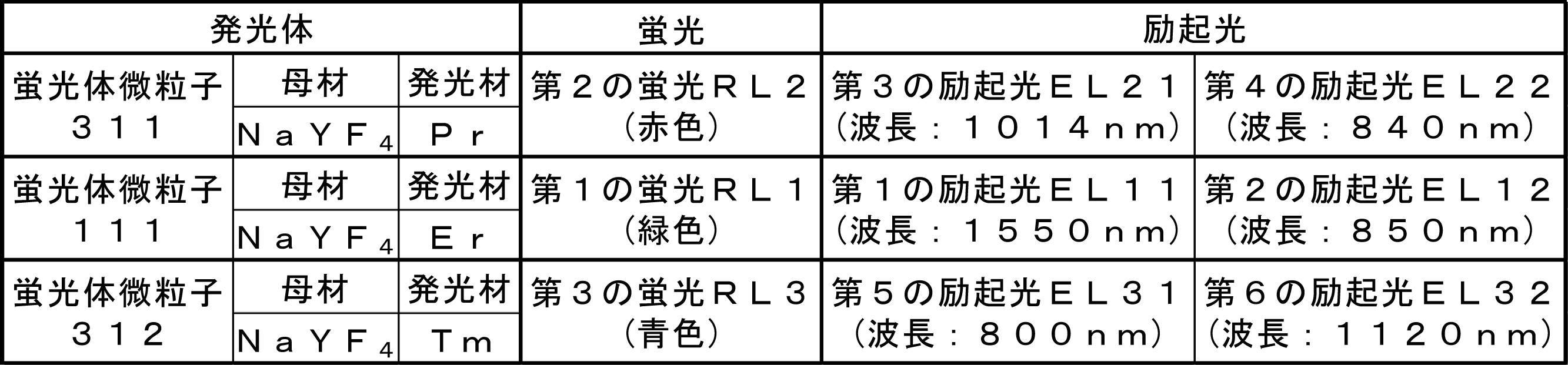
蛍光体微粒子311は、母材のNaYF4に対して発光材のプラセオジウム(Pr)をドープして構成している。蛍光体微粒子311は、第3の励起光EL21(赤外光である波長1014nmの光)と第4の励起光EL22(赤外光である波長840nmの光)によって励起されると、Pr3+イオンのエネルギー準位からの遷移に伴い、可視光である赤色の第2の蛍光RL2を発する。蛍光体微粒子311は、第3の励起光EL21または第4の励起光EL22のみでは蛍光を発しない。
蛍光体微粒子312は、母材のNaYF4に対して発光材のツリウム(Tm)をドープして構成している。蛍光体微粒子312は、第5の励起光EL31(赤外光である波長800nmの光)と第6の励起光EL32(赤外光である波長1120nmの光)によって励起されると、Tm3+イオンのエネルギー準位からの遷移に伴い、可視光である青色の第3の蛍光RL3を発する。蛍光体微粒子312は、第5の励起光EL31または第6の励起光EL32のみでは蛍光を発しない。
図5を参照して、第1光源ユニット320は、上述した第1光源ユニット220の構成に加えて、第3の光源321と第5の光源323等を含んでいる。
第3の光源321は、第3の励起光EL21を発する。第3の光源321は、発振波長に係る光学素子の仕様を除き、第1の光源121と同様の構成からなる。第3の光源321は、第3の励起光EL21を、その波長に適した配光用光ファイバ322に伝搬する。
第5の光源323は、第5の励起光EL31を発する。第5の光源323は、発振波長に係る光学素子の仕様を除き、第1の光源121と同様の構成からなる。第5の光源323は、第5の励起光EL31を、その波長に適した配光用光ファイバ324に伝搬する。
第1の光源121、第3の光源321および第5の光源323の発光のタイミングは、制御ユニット140によって制御する。
合波器325は、例えば、配光用光ファイバ221、配光用光ファイバ322および配光用光ファイバ324の各々の出射部分を加熱して溶融しつつ延伸して構成している。合波器325は、配光用光ファイバ221、配光用光ファイバ322および配光用光ファイバ324から出射された各々の励起光(第1の励起光EL11、第3の励起光EL21および第5の励起光EL31)を合波する。
中継用光ファイバ326は、合波器325によって合波された各々の励起光を配光器327に伝搬する。中継用光ファイバ326は、各々の励起光に対応している。
配光器327は、中継用光ファイバ326から伝搬された各々の励起光を分岐しつつ、複数の第1の光ファイバ328に対して選択的に伝搬する。配光器327は、上述した配光器222と同様の仕様であるが、各々の励起光に対応した構成からなる。複数の第1の光ファイバ328は、第1の励起光EL11、第3の励起光EL21および第5の励起光EL31を、それぞれ表示フィルム112に向かって伝搬させる。
図5を参照して、第2光源ユニット330は、上述した第2光源ユニット230に加えて、第4の光源331と第6の光源333等を含んでいる。
第4の光源331は、第4の励起光EL22を発する。第4の光源331は、発振波長に係る光学素子の仕様を除き、第2の光源131と同様の構成からなる。第4の光源331は、第4の励起光EL22を配光用光ファイバ332に伝搬する。
第6の光源333は、第6の励起光EL32を発する。第6の光源333は、発振波長に係る光学素子の仕様を除き、第2の光源131と同様の構成からなる。第6の光源333は、第6の励起光EL32を配光用光ファイバ334に伝搬する。
第2の光源131、第4の光源331および第6の光源333の発光のタイミングは、制御ユニット140によって制御する。
合波器335は、例えば、配光用光ファイバ231、配光用光ファイバ332および配光用光ファイバ334の各々の出射部分を加熱して溶融しつつ延伸して構成している。合波器335は、配光用光ファイバ231、配光用光ファイバ332および配光用光ファイバ334から出射された各々の励起光(第2の励起光EL12、第4の励起光EL22および第6の励起光EL32)を合波する。
中継用光ファイバ336は、合波器335によって合波された各々の励起光を配光器337に伝搬する。中継用光ファイバ336は、各々の励起光に対応している。
配光器337は、中継用光ファイバ336から伝搬された各々の励起光を分岐しつつ、複数の第2の光ファイバ338に対して選択的に伝搬する。配光器337は、上述した配光器232と同様の仕様であるが、各々の励起光に対応した構成からなる。複数の第2の光ファイバ338は、第2の励起光EL12、第4の励起光EL22および第6の励起光EL32を、それぞれ表示フィルム112に向かって伝搬させる。
以上説明した実施形態の変形例2の作用効果を説明する。
蛍光発光ディスプレイにおいて、表示フィルム112は、蛍光(緑色)とは波長が異なる他の蛍光(赤色および青色)を発する1つ以上の他の発光体(蛍光体微粒子311および蛍光体微粒子312の2つ)をさらに分散させて保持する。蛍光体微粒子111(緑色の蛍光を発する)と蛍光体微粒子311(赤色の蛍光を発する)および蛍光体微粒子312(青色の蛍光を発する)とによって、赤色、緑色および青色の波長の光の蛍光を発する。
かかる蛍光発光ディスプレイによれば、表示フィルム112に表示させる情報を、赤色、緑色および青色の3色を混色することによって、紫から赤色に至るいわゆるフルカラーによって表すことができる。したがって、蛍光発光ディスプレイは、さらに多くの情報を表示することができる。
蛍光発光ディスプレイによれば、合波器325を有することが好ましい。合波器325は、第1の励起光EL11、第3の励起光EL21および第5の励起光EL31を合波して(中継用光ファイバ326および配光器327を介して)第1の光ファイバ328に入射する。
かかる蛍光発光ディスプレイによれば、3種類の波長の励起光に対応した3種類の光ファイバを設ける場合と比較して、光ファイバの数を減らすことができる。したがって、蛍光発光ディスプレイは、光ファイバに要するスペースを削減することができ、表示フィルム112に対する第1の光源121等の配置の自由度をさらに向上させることができる。
また、蛍光発光ディスプレイは、3種類の波長の励起光を互いに独立した3本の光ファイバによって伝搬する場合と比較して、3種類の波長の励起光を1本の第1の光ファイバ328によって密に伝搬させることができる。すなわち、赤色、緑色および青色を互いに独立して伝搬する3本の光ファイバを束ねて用いる場合と比較して、赤色、緑色および青色の光を合波して伝搬する1本の光ファイバを用いた方が、1画素の大きさを小さくすることができる。したがって、アップコンバージョン蛍光発光ディスプレイは、表示フィルム112の解像度をさらに向上させることができる。
また、蛍光発光ディスプレイは、3種類の光ファイバを設ける場合と比較して、第1の光ファイバ328の経年劣化等に伴う交換を容易に行うことができる。したがって、蛍光発光ディスプレイは、メンテナンスに要する手間を低減できる。
また、蛍光発光ディスプレイは、3種類の光ファイバを設ける場合と比較して、第1の光ファイバ328を収めるスペースを削減することができる。したがって、蛍光発光ディスプレイは、小型化することができる。
また、蛍光発光ディスプレイは、3種類の光ファイバを設ける場合と比較して、第1の光ファイバ328に要するコストを軽減することができる。したがって、蛍光発光ディスプレイは、廉価に構成することができる。
ここで、蛍光発光ディスプレイは、第2の励起光EL12、第4の励起光EL22および第6の励起光EL32を合波して(中継用光ファイバ336および配光器337を介して)第2の光ファイバ338に入射する合波器335を有している。したがって、蛍光発光ディスプレイは、合波器335においても、上述した合波器325と同様の作用効果を奏する。
(実施形態の変形例3)
図6は、実施形態の変形例3に係る蛍光発光ディスプレイの要部を模式的に示す斜視図である。
図6は、実施形態の変形例3に係る蛍光発光ディスプレイの要部を模式的に示す斜視図である。
実施形態の変形例3に係る蛍光発光ディスプレイは、より少ない蛍光体微粒子と光源の組み合わせによって情報をフルカラー表示する点において、上述した実施形態の変形例2に係る蛍光発光ディスプレイと相違する。すなわち、実施形態の変形例3では、2種類の蛍光体微粒子と4種類の光源を用いる。上述した実施形態の変形例2では、3種類の蛍光体微粒子と6種類の光源を用いていた。
実施形態の変形例3に係る蛍光発光ディスプレイは、情報をフルカラー表示するための構成を具現化させた「他の形態」である。
蛍光発光ディスプレイにおいて、表示フィルム112は、蛍光(緑色)とは波長が異なる他の蛍光(青色)を発する1つ以上の他の発光体(蛍光体微粒子312の1つ)をさらに分散させて保持している。
この蛍光発光ディスプレイでは、蛍光体微粒子111(赤色および緑色の蛍光を発する)と蛍光体微粒子312(青色の蛍光を発する)とによって、赤色、緑色および青色の波長の光の蛍光を発する。
具体的には、蛍光発光ディスプレイは、蛍光体微粒子111が、第1の励起光EL11と第7の励起光EL42によって励起されると第4の蛍光RL4(赤色)を発する。表示フィルム112は、第8の励起光EL51と第7の励起光EL42によって励起されると第5の蛍光RL5(青色)を発する第4の発光体(蛍光体微粒子312)を、さらに分散させて保持している。第1の蛍光RL1(緑色)、第4の蛍光RL4(赤色)および第5の蛍光RL5(青色)は、赤色、緑色および青色の波長の光の組み合わせからなる。蛍光発光ディスプレイは、第7の励起光EL42を発する第7の光源431と、第8の励起光EL51を発する第8の光源421と、をさらに有する。ここで、複数の第1の光ファイバ426は、第1の励起光EL11および第8の励起光EL51を、表示フィルム112に向かって伝搬させ、複数の第2の光ファイバ436は、第2の励起光EL12および第7の励起光EL42を、表示フィルム112に向かって伝搬させる。
実施形態の変形例3に係る蛍光発光ディスプレイでは、上述した実施形態およびその変形例の構成とは異なる表示ユニット410、第1光源ユニット420および第2光源ユニット430の構成について説明する。
図6を参照して、表示ユニット410において、表示フィルム112は、蛍光体微粒子111に加えて、蛍光体微粒子312を均一かつ密に分散させて保持している。
表3に、蛍光体微粒子111および蛍光体微粒子312の光学特性を示す。
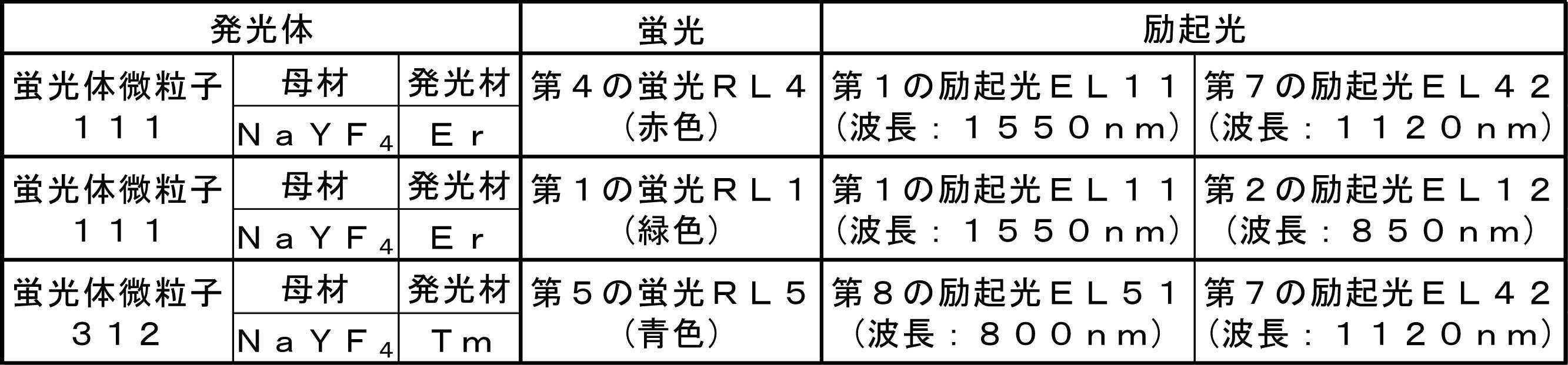
上述した蛍光体微粒子111は、それぞれ第1の励起光EL11(赤外光である波長1550nmの光)と第7の励起光EL42(赤外光である波長1120nmの光)によって励起されると、Er3+イオンのエネルギー準位からの遷移に伴い、可視光である赤色の波長の光に相当する第4の蛍光RL4を発する。蛍光体微粒子111は、第1の励起光EL11または第7の励起光EL42のみでは蛍光を発しない。
上述した蛍光体微粒子312は、第8の励起光EL51(赤外光である波長800nmの光)と第7の励起光EL42によって励起されると、Tm3+イオンのエネルギー準位からの遷移に伴い、可視光である青色の第5の蛍光RL5を発する。蛍光体微粒子312は、第8の励起光EL51または第7の励起光EL42のみでは蛍光を発しない。
図6を参照して、第1光源ユニット420は、上述した第1光源ユニット220の構成に加えて、第8の光源421等を含んでいる。
第8の光源421は、上述した第8の励起光EL51を発する。第8の光源421は、発振波長に係る光学素子の仕様を除き、第1の光源121と同様の構成からなる。第8の光源421は、第8の励起光EL51を、その波長に適した配光用光ファイバ422に伝搬する。
第1の光源121および第8の光源421の発光のタイミングは、制御ユニット140によって制御する。
合波器423は、例えば、配光用光ファイバ221および配光用光ファイバ422の各々の出射部分を加熱して溶融しつつ延伸して構成している。合波器423は、配光用光ファイバ221および配光用光ファイバ422から出射された各々の励起光(第1の励起光EL11および第8の励起光EL51)を合波する。
中継用光ファイバ424は、合波器423によって合波された各々の励起光を配光器425に伝搬する。中継用光ファイバ424は、各々の励起光に対応している。
配光器425は、中継用光ファイバ424から伝搬された各々の励起光を分岐しつつ、複数の第1の光ファイバ426に対して選択的に伝搬する。配光器425は、上述した配光器222と同様の仕様であるが、各々の励起光に対応した構成からなる。複数の第1の光ファイバ426は、第1の励起光EL11および第8の励起光EL51を、それぞれ表示フィルム112に向かって伝搬させる。
図6を参照して、第2光源ユニット430は、上述した第2光源ユニット230の構成に加えて、第7の光源431等を含んでいる。
第7の光源431は、上述した第7の励起光EL42を発する。第7の光源431は、発振波長に係る光学素子の仕様を除き、第2の光源131と同様の構成からなる。第7の光源431は、第7の励起光EL42を、その波長に適した配光用光ファイバ432に伝搬する。
第2の光源131および第7の光源431の発光のタイミングは、制御ユニット140によって制御する。
合波器433は、例えば、配光用光ファイバ231および配光用光ファイバ432の各々の出射部分を加熱して溶融しつつ延伸して構成している。合波器433は、配光用光ファイバ231および配光用光ファイバ432から出射された各々の励起光(第2の励起光EL12および第7の励起光EL42)を合波する。
中継用光ファイバ434は、合波器433によって合波された各々の励起光を配光器435に伝搬する。中継用光ファイバ434は、各々の励起光に対応している。
配光器435は、中継用光ファイバ434から伝搬された各々の励起光を分岐しつつ、複数の第2の光ファイバ436に対して選択的に伝搬する。配光器435は、上述した配光器232と同様の仕様であるが、各々の励起光に対応した構成からなる。複数の第2の光ファイバ436は、第2の励起光EL12および第7の励起光EL42を、それぞれ表示フィルム112に向かって伝搬させる。
以上説明した実施形態の変形例3の作用効果を説明する。
蛍光発光ディスプレイにおいて、表示フィルム112は、蛍光(緑色)とは波長が異なる他の蛍光(青色)を発する1つ以上の他の発光体(蛍光体微粒子312の1つ)をさらに分散させて保持している。蛍光体微粒子111(赤色および緑色の蛍光を発する)と蛍光体微粒子312(青色の蛍光を発する)とによって、赤色、緑色および青色の波長の光の蛍光を発する。
かかる蛍光発光ディスプレイによれば、2種類の蛍光体微粒子と4種類の光源を用いた場合においても、表示フィルム112に表示させる情報を、赤色、緑色および青色の3色を混色することによって、紫から赤色に至るいわゆるフルカラーによって表すことができる。したがって、蛍光発光ディスプレイは、光源の種類を削減することによって表示フィルム112に対する光源の配置の自由度をさらに向上させつつ、多くの情報を表示させることができる。
(実施形態の変形例4)
図7は、実施形態の変形例4に係る蛍光発光ディスプレイの要部を模式的に示す上面図である。
図7は、実施形態の変形例4に係る蛍光発光ディスプレイの要部を模式的に示す上面図である。
実施形態の変形例4に係る蛍光発光ディスプレイは、表示フィルム112から励起光が漏れ出さないように、表示フィルム112に透明な被覆部材511を貼り付けた点において、上述した実施形態に係る蛍光発光ディスプレイ100と相違する。
実施形態の変形例4に係る蛍光発光ディスプレイでは、上述した実施形態およびその変形例の構成とは異なる表示ユニット510の構成について説明する。
図7を参照して、表示ユニット510において、被覆部材511は、表示フィルム112よりも薄いフィルム状に形成している。被覆部材511は、可視光(紫色~赤色)の全域において透明な材質から構成している。被覆部材511は、第1の励起光EL11、第2の励起光EL12、第3の励起光EL21、第4の励起光EL22、第5の励起光EL31、第6の励起光EL32、第7の励起光EL42および第8の励起光EL51の波長の光において表示フィルム112よりも屈折率が小さい材質から構成している。被覆部材511は、例えば一対からなり、表示フィルム112の両面に対して密着させるようにして接着している。
表示フィルム112と被覆部材511は、いわゆる光ファイバのコアとクラッド(コアよりも屈折率が小さい)の関係に対応している。すなわち、第1の励起光EL11および第2の励起光EL12は、表示フィルム112の第1表示面112aと被覆部材511との界面、および表示フィルム112の第2表示面112bと被覆部材511との界面で反射しつつ、表示フィルム112の内部を伝搬する。
以上説明した実施形態の変形例4の作用効果を説明する。
蛍光発光ディスプレイは、被覆部材511を有する。被覆部材511は、表示フィルム112に当接し、第1の励起光EL11および第2の励起光EL12の波長の光において表示フィルム112よりも屈折率が小さい。
かかる蛍光発光ディスプレイによれば、表示フィルム112の内部を伝搬する第1の励起光EL11および第2の励起光EL12が、表示フィルム112と被覆部材511との界面で反射することによって、表示フィルム112から外部に出射することを防止できる。したがって、蛍光発光ディスプレイは、表示フィルム112において適切に情報を表示させることができる。すなわち、被覆部材511は、表示フィルム112の任意の面に当接させることによって、その面から第1の励起光EL11および第2の励起光EL12が外部に出射してしまうことを防止する部材として用いることができる。
ここで、蛍光発光ディスプレイは、表示フィルム112の片面に被覆部材511を備えている場合、フロントガラス11の側に被覆部材511が対向するようにして、例えばフロントガラス11に貼り付けて用いる。このように構成すれば、表示フィルム112の内部を伝搬する第1の励起光EL11および第2の励起光EL12は、表示フィルム112からフロントガラス11に入射することなく、表示フィルム112と被覆部材511との界面で反射して、表示フィルム112の内部を伝搬し続ける。したがって、蛍光発光ディスプレイは、フロントガラス11に阻害されることなく、表示フィルム112において適切に情報を表示させることができる。
また、蛍光発光ディスプレイが、表示フィルム112の両面に被覆部材511を備えている場合、フロントガラス11の側に加えて、車両10の室内の側にも被覆部材511を対向させて用いることができる。このように構成すれば、表示フィルム112を伝搬する第1の励起光EL11および第2の励起光EL12が、車両10の室内の側に位置する被覆部材511に付着した水滴や油膜に入射することなく、表示フィルム112と被覆部材511との界面で反射して、表示フィルム112の内部を伝搬し続ける。したがって、蛍光発光ディスプレイは、車両10の室内の側から付着した水滴や油膜に阻害されることなく、表示フィルム112において適切に情報を表示させることができる。
(実施形態の変形例5)
図8Aは、実施形態の変形例5-1に係る蛍光発光ディスプレイ600の表示方法を模式的に示す正面図である。図8Bは、図8Aに示す表示方法の対比例1に係る蛍光発光ディスプレイ1600の表示方法を模式的に示す正面図である。図9は、実施形態の変形例5-1に係る励起光の照射時間と蛍光の強度との関係を示す図である。図10Aは、実施形態の変形例5-2に係る蛍光発光ディスプレイ700の表示方法を模式的に示す正面図である。図10Bは、図10Aに示す表示方法の対比例2に係る蛍光発光ディスプレイ1700の表示方法を模式的に示す正面図である。図11Aは、実施形態の変形例5-3に係る蛍光発光ディスプレイ800の表示方法を模式的に示す正面図である。図11Bは、図11Aに示す表示方法の対比例3に係る蛍光発光ディスプレイ1800の表示方法を模式的に示す正面図である。
図8Aは、実施形態の変形例5-1に係る蛍光発光ディスプレイ600の表示方法を模式的に示す正面図である。図8Bは、図8Aに示す表示方法の対比例1に係る蛍光発光ディスプレイ1600の表示方法を模式的に示す正面図である。図9は、実施形態の変形例5-1に係る励起光の照射時間と蛍光の強度との関係を示す図である。図10Aは、実施形態の変形例5-2に係る蛍光発光ディスプレイ700の表示方法を模式的に示す正面図である。図10Bは、図10Aに示す表示方法の対比例2に係る蛍光発光ディスプレイ1700の表示方法を模式的に示す正面図である。図11Aは、実施形態の変形例5-3に係る蛍光発光ディスプレイ800の表示方法を模式的に示す正面図である。図11Bは、図11Aに示す表示方法の対比例3に係る蛍光発光ディスプレイ1800の表示方法を模式的に示す正面図である。
実施形態の変形例5-1、5-2、および5-3に係る蛍光発光ディスプレイ600、700、および800は、情報(例えば矢印)を表示させる特定の位置のみにおいて第1の励起光EL11と第2の励起光EL12とを交差させるように、第1の励起光EL11を伝播させる光ファイバ(第1の光ファイバ122)と第2の励起光EL12を伝播させる光ファイバ(第2の光ファイバ132)とを選択的に用いるように制御する。
具体的には、実施形態の変形例5-1、5-2、および5-3に係る蛍光発光ディスプレイ600、700、および800は、ベクタースキャン方式によって、第1の励起光EL11および第2の励起光EL12を走査する。以下、具体的に説明する。
表4に、実施形態の変形例5-1に係る蛍光発光ディスプレイ600(図8A)と、対比例1に係る蛍光発光ディスプレイ1600(図8B)の仕様を示す。
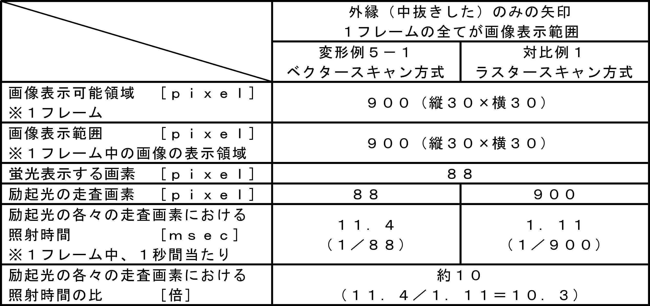
図8Aに示す蛍光発光ディスプレイ600において、第1光源ユニット620は、第1の光ファイバ122から出射された第1の励起光EL11を、第1のコリメータレンズ123によってコリメートしつつ、表示ユニット110の表示フィルム112に伝搬する。第2光源ユニット630は、第2の光ファイバ132から出射された第2の励起光EL12を、第2のコリメータレンズ133によってコリメートしつつ、表示フィルム112に伝搬する。
図8Aに示す蛍光発光ディスプレイ600と、図8Bに示す対比例1の蛍光発光ディスプレイ1600は、表示ユニット110の表示フィルム112における画像表示可能領域が、それぞれ900(縦30×横30)ピクセルである。蛍光発光ディスプレイ600および蛍光発光ディスプレイ1600は、1フレームが、それぞれ900ピクセルから構成されている。
蛍光発光ディスプレイ600と、蛍光発光ディスプレイ1600は、1フレームの全面(900ピクセル)に、それぞれ画像を表示させる。すなわち、蛍光発光ディスプレイ600および蛍光発光ディスプレイ1600は、画像表示可能領域と画像表示範囲が等しい。
蛍光発光ディスプレイ600および蛍光発光ディスプレイ1600には、一例として、外縁のみで中抜きした矢印からなる情報を表示させる。図8Aおよび図8Bに示す表示フィルム112において、外縁のみで中抜きした矢印からなる情報は、合計88ピクセルを矢印の形を構成するように蛍光発光させて表示する。
ベクタースキャン方式の蛍光発光ディスプレイ600では、1フレーム(900ピクセル)中において、蛍光発光させる88ピクセルのみに対して、励起光を照射するように制御する。ベクタースキャン方式では、画像表示可能領域に含まれる画素に対して、情報を表示する(蛍光を発光させる)画素のみに、信号(励起光)をONしながら走査(照射)する。したがって、蛍光発光ディスプレイ600は、蛍光発光させる88ピクセルの各々のピクセルに対して、1フレーム中、1秒間当たり、11.4msec(1sec/88ピクセル)の間、励起光を照射することができる。
ラスタースキャン方式の蛍光発光ディスプレイ1600では、1フレーム(900ピクセル)中において、蛍光発光の要否に関わらず全ての900ピクセルに対して、励起光を選択的に照射するように制御する。ラスタースキャン方式では、画像表示可能領域に含まれる複数の画素に対して、情報を表示する(蛍光を発光させる)画素と情報を表示しない(蛍光を発光させない)画素に、信号(励起光)を選択的にON/OFFしながら走査(照射)する。蛍光発光ディスプレイ1600は、蛍光発光させる88ピクセルに対して励起光を照射し(ON)、それ以外の812(900-88)ピクセルに対して動作を停止して励起光を照射しない(OFF)。したがって、蛍光発光ディスプレイ1600は、蛍光発光させる88ピクセルの各々のピクセルに対して、1フレーム中、1秒間当たり、1.11msec(1sec/900ピクセル)の間しか、励起光を照射することができない。
ベクタースキャン方式の蛍光発光ディスプレイ600は、ラスタースキャン方式の蛍光発光ディスプレイ1600と比較して、蛍光発光させる88ピクセルの各々のピクセルに対して、励起光を約10(11.4/1.11=10.3)倍、長く照射することができる。図9に示すように、1つの画素における単位時間当たりの励起光の照射時間を長くすると、励起光の光強度が一定の場合、蛍光の輝度が上がる。すなわち、1つの画素において発光させる蛍光を視認し易くなる。
表5に、実施形態の変形例5-2に係る蛍光発光ディスプレイ700(図10A)と、対比例2に係る蛍光発光ディスプレイ1700(図10B)の仕様を示す。
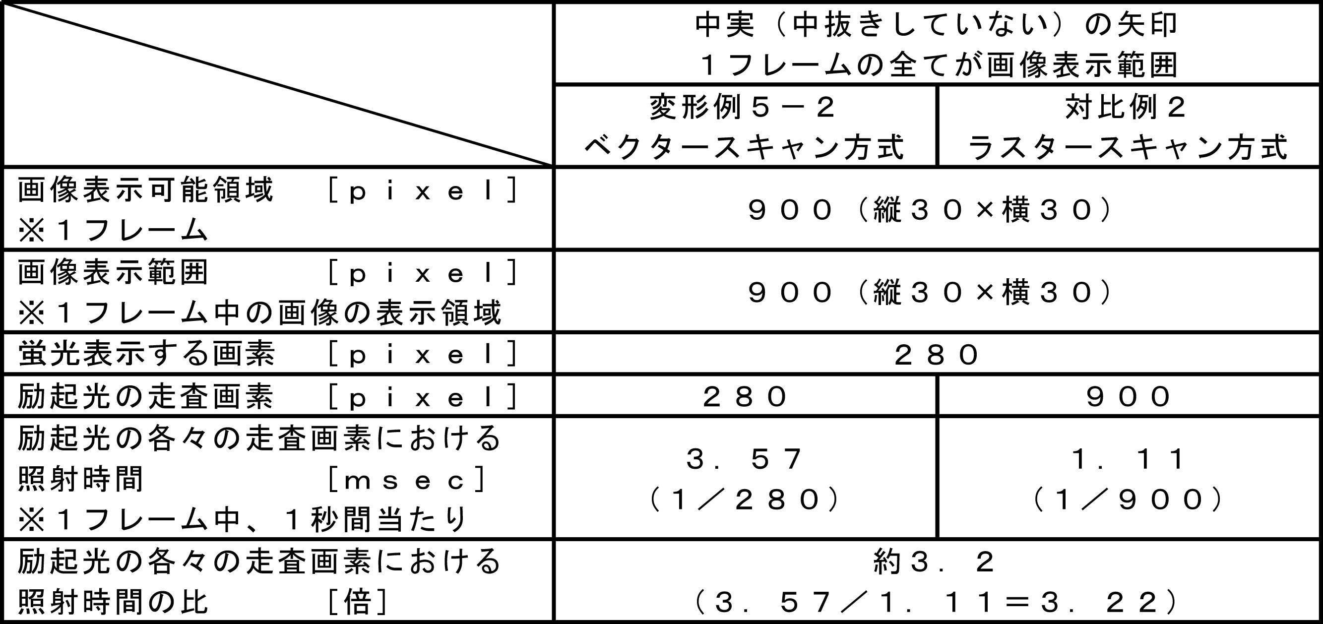
図10Aに示す蛍光発光ディスプレイ700において、第1光源ユニット720は、第1の光ファイバ122から出射された第1の励起光EL11を、第1のコリメータレンズ123によってコリメートしつつ、表示ユニット110の表示フィルム112に伝搬する。第2光源ユニット730は、第2の光ファイバ132から出射された第2の励起光EL12を、第2のコリメータレンズ133によってコリメートしつつ、表示フィルム112に伝搬する。
図10Aに示す蛍光発光ディスプレイ700と、図10Bに示す対比例2の蛍光発光ディスプレイ1700は、表示ユニット110の表示フィルム112における画像表示可能領域が、それぞれ900(縦30×横30)ピクセルである。蛍光発光ディスプレイ700および蛍光発光ディスプレイ1700は、1フレームが、それぞれ900ピクセルから構成されている。
蛍光発光ディスプレイ700と、蛍光発光ディスプレイ1700は、1フレームの全面(900ピクセル)に、それぞれ画像を表示させる。すなわち、蛍光発光ディスプレイ700と蛍光発光ディスプレイ1700は、画像表示可能領域と画像表示範囲が等しい。
蛍光発光ディスプレイ700および蛍光発光ディスプレイ1700には、一例として、中実で中抜きしていない矢印からなる情報を表示させる。図10Aおよび図10Bに示す表示フィルム112において、中実で中抜きしていない矢印からなる情報は、合計280ピクセルを矢印の形を構成するように蛍光発光させて表示する。
ベクタースキャン方式の蛍光発光ディスプレイ700では、1フレーム(900ピクセル)中において、蛍光発光させる280ピクセルのみに対して、励起光を照射するように制御する。したがって、蛍光発光ディスプレイ700は、蛍光発光させる280ピクセルの各々のピクセルに対して、1フレーム中、1秒間当たり、3.57msec(1sec/280ピクセル)の間、励起光を照射することができる。
ラスタースキャン方式の蛍光発光ディスプレイ1700では、1フレーム(900ピクセル)中において、蛍光発光の要否に関わらず全ての900ピクセルに対して、励起光を選択的に照射するように制御する。蛍光発光ディスプレイ1700は、蛍光発光させる280ピクセルに対して励起光を照射し(ON)、それ以外の620(900-280)ピクセルに対して動作を停止して励起光を照射しない(OFF)。したがって、蛍光発光ディスプレイ1700は、蛍光発光させる280ピクセルの各々のピクセルに対して、1フレーム中、1秒間当たり、1.11msec(1sec/900ピクセル)の間しか、励起光を照射することができない。
ベクタースキャン方式の蛍光発光ディスプレイ700は、ラスタースキャン方式の蛍光発光ディスプレイ1700と比較して、蛍光発光させる280ピクセルの各々のピクセルに対して、励起光を約3.2(3.57/1.11=3.22)倍、長く照射することができる。
表6に、実施形態の変形例5-3に係る蛍光発光ディスプレイ800(図11A)と、対比例3に係る蛍光発光ディスプレイ1800(図11B)の仕様を示す。

図11Aに示す蛍光発光ディスプレイ800において、第1光源ユニット820は、第1の光ファイバ122から出射された第1の励起光EL11を、第1のコリメータレンズ123によってコリメートしつつ、表示ユニット810の表示フィルム812に伝搬する。第2光源ユニット830は、第2の光ファイバ132から出射された第2の励起光EL12を、第2のコリメータレンズ133によってコリメートしつつ、表示フィルム812に伝搬する。
図11Aに示す蛍光発光ディスプレイ800と、図11Bに示す対比例3の蛍光発光ディスプレイ1800は、表示ユニット810の表示フィルム812における画像表示可能領域が、それぞれ14400(縦60×横240)ピクセルである。蛍光発光ディスプレイ800および蛍光発光ディスプレイ1800は、1フレームが、それぞれ14400ピクセルから構成されている。
蛍光発光ディスプレイ800と、蛍光発光ディスプレイ1800は、1フレームの一部分(900ピクセル)に、それぞれ画像を表示させる。すなわち、蛍光発光ディスプレイ800および蛍光発光ディスプレイ1800は、画像表示可能領域と画像表示範囲が等しくない。画像表示範囲は、例えば、画像表示可能領域の端部に位置する。画像表示可能領域は、画像表示範囲の16倍である。
蛍光発光ディスプレイ800および蛍光発光ディスプレイ1800には、一例として、外縁のみで中抜きした矢印からなる情報を表示させる。図11Aおよび図11Bに示す表示フィルム112において、外縁のみで中抜きした矢印からなる情報は、合計88ピクセルを矢印の形を構成するように蛍光発光させて表示する。
ベクタースキャン方式の蛍光発光ディスプレイ800では、1フレーム(14400ピクセル)中において、蛍光発光させる88ピクセルのみに対して、励起光を照射するように制御する。したがって、蛍光発光ディスプレイ800は、蛍光発光させる88ピクセルの各々のピクセルに対して、1フレーム中、1秒間当たり、11.4msec(1sec/88ピクセル)の間、励起光を照射することができる。
ラスタースキャン方式の蛍光発光ディスプレイ1800では、1フレーム(14400ピクセル)中において、蛍光発光の要否に関わらず全ての14400ピクセルに対して、励起光を選択的に照射するように制御する。蛍光発光ディスプレイ1800は、蛍光発光させる88ピクセルに対して励起光を照射し(ON)、それ以外の14312(14400-88)ピクセルに対して動作を停止して励起光を照射しない(OFF)。したがって、蛍光発光ディスプレイ1800は、蛍光発光させる88ピクセルの各々のピクセルに対して、1フレーム中、1秒間当たり、6.94×10⁻²msec(1sec/14400ピクセル)の間しか、励起光を照射することができない。
ベクタースキャン方式の蛍光発光ディスプレイ800は、ラスタースキャン方式の蛍光発光ディスプレイ1800と比較して、蛍光発光させる88ピクセルの各々のピクセルに対して、励起光を約160{11.4/(6.94×10-2)=164}倍、長く照射することができる。
以上説明した実施形態の変形例5の作用効果を説明する。
表示装置の制御方法は、情報(例えば矢印)を表示させる特定の位置のみにおいて第1の励起光EL11と第2の励起光EL12とを交差させるように、第1の励起光EL11を伝播させる第1の光ファイバ122と第2の励起光EL12を伝播させる第2の光ファイバ132とを選択的に用いるように制御する。
かかる表示装置の制御方法は、いわゆるベクタースキャン方式を用いた制御方法である。この表示装置の制御方法は、いわゆるラスタースキャン方式を用いた制御方法と比較して、画像表示可能領域において情報(矢印)を表示させる(蛍光発光させる)画素に対して、励起光を長く照射することができる。1つの画素における単位時間当たりの励起光の照射時間を長くすると、励起光の光強度が一定の場合、その画素における蛍光の輝度が上がる。したがって、この表示装置の制御方法は、情報(蛍光によって表される矢印)を視認し易くすることができる。
特に、かかる表示装置の制御方法は、画像表示可能領域の一部分にしか画像を表示させない場合(変形例5-3)に、ラスタースキャン方式を用いた制御方法と比較して、情報(矢印)を表示させる(蛍光発光させる)画素に対して、励起光を非常に長く照射することができる。したがって、この表示装置の制御方法は、画像表示可能領域の一部分にしか画像を表示させない場合(変形例5-3)に、ラスタースキャン方式を用いた制御方法と比較して、情報(蛍光によって表される矢印)を非常に視認し易くすることができる。
また、かかる表示装置の制御方法は、情報(蛍光によって表される矢印)を視認し易くすることによって、一例として、明るい環境(真夏の晴天時)において、表示フィルム(フロントガラス11に貼り付けられている状態)を透過する可視光線(太陽光)に対して、コントラストを十分に保つことができる。
そのほか、本発明は、特許請求の範囲に記載された構成に基づき様々な改変が可能であり、それらについても本発明の範疇である。
例えば、実施形態において、蛍光発光ディスプレイ100は、第1の励起光EL11および第2の励起光EL12を伝搬させる光学部材に、コアの直径を任意に選択できる光ファイバを用いている。したがって、蛍光発光ディスプレイ100は、コアの直径が異なる複数種類の光ファイバを組み合わせて、表示フィルム112に入射させる第1の励起光EL11および第2の励起光EL12のビーム形状を任意に設定することができる。このようなことから、コアの直径が十分に小さい光ファイバを選択することによって、表示フィルム112の特定の領域については、表示画素を小さくして分解能を上げて、情報を密に表示することができる。密に表示する情報は、蛍光発光ディスプレイ100を車両10に用いる場合、例えば数字や文字で表されるものであって、車両10の速度等の情報である。一方、コアの直径が上記の仕様よりも大きい光ファイバを選択することによって、表示フィルム112の他の領域については、表示画素を大きくして、情報を大まかに表示するようなことができる。大まかに表示する情報は、蛍光発光ディスプレイ100を車両10に用いる場合、例えば人型の図形で表されるものであって、車両10の進行方向に存在する歩行者等の情報である。
また、実施形態において、表示フィルム112を板状やフィルム状に形成し、情報を2次元で表示する構成として説明したが、このような構成に限定されることはない。例えば、表示フィルム112を長方体形状に形成し、かつ、格子状に配置した第1の光ファイバ122と、格子状に配置した第2の光ファイバ132によって、情報を立体的に表示する構成としてもよい。
また、実施形態において、第1の励起光EL11および第2の励起光EL12は、表示フィルム112の異なる面から内部に入射させる構成として説明したが、このような構成に限定されることはない。例えば、第1の励起光EL11および第2の励起光EL12は、表示フィルム112の同一の面から内部に入射させる構成としてもよい。すなわち、第1の入射面と第2の入射面は、同一の面から構成してもよい。この場合、第1の励起光EL11および第2の励起光EL12は、表示フィルム112の面に対してそれぞれ斜入射させて、表示フィルム112の内部において互いに交差させる。
また、実施形態において、蛍光発光ディスプレイは、車両10に用いる表示装置として説明したが、このような構成に限定されることはない。例えば、蛍光発光ディスプレイは、いわゆるテレビとして様々な情報を表示したり、屋外に設置して交通や広告に関する情報を表示したりする構成としてもよい。
また、実施形態において、蛍光発光ディスプレイをフロントガラス11に貼り付けて用いる構成として説明したが、このような構成に限定されることはない。例えば、蛍光発光ディスプレイを車両10のダッシュボードの運転席に対向する側面に貼り付けて用いる構成としてもよい。
また、実施形態において、伝搬部材(第1の伝搬部材および第2の伝搬部材)は、例えば、コリメータレンズ(第1のコリメータレンズ123および第2のコリメータレンズ133)を含む。複数のコリメータレンズを1個のアレイレンズによって構成した場合、1個のアレイレンズに含まれる各々のレンズが、それぞれ伝搬部材に相当する。
また、実施形態の変形例5は、実施形態の変形例1~4の構成にも、適用することができる。実施形態の変形例5を、実施形態の変形例1~3の構成に適用する場合、ガルバノミラー方式や、MEMS(Micro Electro Mechanical Systems)方式によって、複数の光ファイバに対して励起光を選択的に伝搬させる。
本出願は、2016年5月23日に出願された日本特許出願番号2016-102696号と、2017年3月13日に出願された日本特許出願番号2017-47199号に基づいており、その開示内容は、参照され、全体として、組み入れられている。
10 車両、
11 フロントガラス、
100,600,700,800,1600,1700,1800 蛍光発光ディスプレイ(表示装置)、
110,310,410,510,810 表示ユニット、
111 蛍光体微粒子(第1の発光体)、
112,812 表示フィルム(表示媒体)、
112a 第1表示面(表示面)、
112b 第2表示面(表示面)、
112c 第1端面(第1の入射面)、
112d 第2端面(第2の入射面)、
311 蛍光体微粒子(第2の発光体)、
312 蛍光体微粒子(第3の発光体,第4の発光体)、
511 被覆部材、
120,220,320,420,620,720,820,1620,1720,1820 第1光源ユニット、
121 第1の光源、
122,328,426 第1の光ファイバ(第1の伝搬部材)、
123 第1のコリメータレンズ、
124 電線、
511 被覆部材、
221,322,324,422 配光用光ファイバ、
222,425 配光器、
321 第3の光源、
323 第5の光源、
325 合波器、
326,424 中継用光ファイバ、
327 配光器、
421 第8の光源、
423 合波器、
130,230,330,430,630,730,830,1630,1730,1830 第2光源ユニット、
131 第2の光源、
132,338,436 第2の光ファイバ(第2の伝搬部材)、
133 第2のコリメータレンズ、
134 電線、
331 第4の光源、
231,332,334,432 配光用光ファイバ、
232,337 配光器、
333 第6の光源、
335,433 合波器、
336,434 中継用光ファイバ、
431 第7の光源、
435 配光器、
140 制御ユニット(制御部材)、
EL11 第1の励起光(赤外光である波長1550nmの光)、
EL12 第2の励起光(赤外光である波長850nmの光)、
EL21 第3の励起光(赤外光である波長1014nmの光)、
EL22 第4の励起光(赤外光である波長840nmの光)、
EL31 第5の励起光(赤外光である波長800nmの光)、
EL32 第6の励起光(赤外光である波長1120nmの光)、
EL42 第7の励起光(赤外光である波長1120nmの光)、
EL51 第8の励起光(赤外光である波長800nmの光)、
RL1 第1の蛍光(可視光である緑色の波長の光)、
RL2 第2の蛍光(可視光である赤色の波長の光)、
RL3 第3の蛍光(可視光である青色の波長の光)、
RL4 第4の蛍光(可視光である赤色の波長の光)、
RL5 第5の蛍光(可視光である青色の波長の光)、
X 表示フィルム112における第1の励起光EL11等の伝搬方向、
Y 表示フィルム112における第2の励起光EL12等の伝搬方向、
Z 表示フィルム112の厚み方向。
11 フロントガラス、
100,600,700,800,1600,1700,1800 蛍光発光ディスプレイ(表示装置)、
110,310,410,510,810 表示ユニット、
111 蛍光体微粒子(第1の発光体)、
112,812 表示フィルム(表示媒体)、
112a 第1表示面(表示面)、
112b 第2表示面(表示面)、
112c 第1端面(第1の入射面)、
112d 第2端面(第2の入射面)、
311 蛍光体微粒子(第2の発光体)、
312 蛍光体微粒子(第3の発光体,第4の発光体)、
511 被覆部材、
120,220,320,420,620,720,820,1620,1720,1820 第1光源ユニット、
121 第1の光源、
122,328,426 第1の光ファイバ(第1の伝搬部材)、
123 第1のコリメータレンズ、
124 電線、
511 被覆部材、
221,322,324,422 配光用光ファイバ、
222,425 配光器、
321 第3の光源、
323 第5の光源、
325 合波器、
326,424 中継用光ファイバ、
327 配光器、
421 第8の光源、
423 合波器、
130,230,330,430,630,730,830,1630,1730,1830 第2光源ユニット、
131 第2の光源、
132,338,436 第2の光ファイバ(第2の伝搬部材)、
133 第2のコリメータレンズ、
134 電線、
331 第4の光源、
231,332,334,432 配光用光ファイバ、
232,337 配光器、
333 第6の光源、
335,433 合波器、
336,434 中継用光ファイバ、
431 第7の光源、
435 配光器、
140 制御ユニット(制御部材)、
EL11 第1の励起光(赤外光である波長1550nmの光)、
EL12 第2の励起光(赤外光である波長850nmの光)、
EL21 第3の励起光(赤外光である波長1014nmの光)、
EL22 第4の励起光(赤外光である波長840nmの光)、
EL31 第5の励起光(赤外光である波長800nmの光)、
EL32 第6の励起光(赤外光である波長1120nmの光)、
EL42 第7の励起光(赤外光である波長1120nmの光)、
EL51 第8の励起光(赤外光である波長800nmの光)、
RL1 第1の蛍光(可視光である緑色の波長の光)、
RL2 第2の蛍光(可視光である赤色の波長の光)、
RL3 第3の蛍光(可視光である青色の波長の光)、
RL4 第4の蛍光(可視光である赤色の波長の光)、
RL5 第5の蛍光(可視光である青色の波長の光)、
X 表示フィルム112における第1の励起光EL11等の伝搬方向、
Y 表示フィルム112における第2の励起光EL12等の伝搬方向、
Z 表示フィルム112の厚み方向。
Claims (12)
- 第1の励起光と第2の励起光とを含む複数の励起光によって励起されると前記複数の励起光よりも波長が短い蛍光を発する発光体を分散させて保持し、前記蛍光を表示させる表示媒体と、
前記第1の励起光を発する第1の光源と、
前記第1の励起光を前記表示媒体の第1の入射面から内部に伝搬する複数の第1の伝搬部材と、
前記第2の励起光を発する第2の光源と、
前記第1の励起光と交差させるように前記第2の励起光を前記表示媒体の第2の入射面から内部に伝搬する複数の第2の伝搬部材と、
前記表示媒体の特定の位置において前記第1の励起光と前記第2の励起光とを交差させるように前記第1の光源および前記第2の光源を制御する制御部材と、を有し、
少なくとも、前記第1の光源は前記表示媒体から離間して配置し、前記第1の伝搬部材は光ファイバを含む表示装置。 - 前記光ファイバの出射面は、前記表示媒体の前記蛍光を表示させる表示面と交差した端面に対向している請求項1に記載の表示装置。
- 前記光ファイバの出射面と前記表示媒体との間にコリメータレンズを、さらに有する請求項1または2に記載の表示装置。
- 前記第1の励起光を分岐して複数の前記光ファイバに入射させる配光器を、さらに有する請求項1~3のいずれか1項に記載の表示装置。
- 前記表示媒体は、前記蛍光とは波長が異なる他の蛍光を発する1つ以上の他の発光体をさらに分散させて保持し、
前記発光体と1以上の前記他の発光体とによって、赤色、緑色および青色の波長の光の蛍光を発し、
前記発光体または1以上の前記他の発光体を励起する他の励起光を発する他の光源を、さらに有し、
複数の前記第1の伝搬部材または複数の前記第2の伝搬部材は、さらに前記他の励起光を前記表示媒体に向かって伝搬させる請求項1~4のいずれか1項に記載の表示装置。 - 前記励起光と前記他の励起光を合波して前記光ファイバに入射させる合波器を、さらに有する請求項5に記載の表示装置。
- 前記表示媒体に当接し、前記第1の励起光および前記第2の励起光の波長において前記表示媒体よりも屈折率が小さい被覆部材を、さらに有する請求項1~6のいずれか1項に記載の表示装置。
- 前記第1の光源は、複数備え、
前記第2の光源は、複数備え、
前記制御部材は、前記表示媒体の特定の位置に対応する特定の前記第1の光源および前記第2の光源を制御する請求項1~7のいずれか1項に記載の表示装置。 - 前記第2の光源は前記表示媒体から離間して配置し、前記第2の伝搬部材は光ファイバを含む請求項1~8のいずれか1項に記載の表示装置。
- 前記表示媒体を車両のフロントガラスに貼り付けて用いる請求項1~9のいずれか1項に記載の表示装置。
- 第1の励起光と第2の励起光とを含む複数の励起光によって励起されると前記複数の励起光よりも波長が短い蛍光を発する発光体を分散させて保持し前記蛍光を表示させる表示媒体に対して、前記第1の励起光と前記第2の励起光とを特定の位置において交差させるようにして伝搬して前記蛍光を発生させることによって情報を表示するように制御する表示装置の制御方法であって、
少なくとも、前記第1の励起光を複数の光ファイバを含む伝搬部材を介して前記表示媒体に伝搬させて前記情報を表示するように制御する表示装置の制御方法。 - 前記情報を表示させる特定の位置のみにおいて前記第1の励起光と前記第2の励起光とを交差させるように、前記第1の励起光を伝播させる前記光ファイバと前記第2の励起光を伝播させる前記光ファイバとを選択的に用いるように制御する請求項11に記載の表示装置の制御方法。
Applications Claiming Priority (4)
| Application Number | Priority Date | Filing Date | Title |
|---|---|---|---|
| JP2016102696 | 2016-05-23 | ||
| JP2016-102696 | 2016-05-23 | ||
| JP2017-047199 | 2017-03-13 | ||
| JP2017047199 | 2017-03-13 |
Publications (1)
| Publication Number | Publication Date |
|---|---|
| WO2017203894A1 true WO2017203894A1 (ja) | 2017-11-30 |
Family
ID=60412742
Family Applications (1)
| Application Number | Title | Priority Date | Filing Date |
|---|---|---|---|
| PCT/JP2017/015499 Ceased WO2017203894A1 (ja) | 2016-05-23 | 2017-04-17 | 表示装置および表示装置の制御方法 |
Country Status (1)
| Country | Link |
|---|---|
| WO (1) | WO2017203894A1 (ja) |
Cited By (1)
| Publication number | Priority date | Publication date | Assignee | Title |
|---|---|---|---|---|
| WO2020114199A1 (zh) * | 2018-12-04 | 2020-06-11 | 深圳市绎立锐光科技开发有限公司 | 一种照明光源及车灯 |
Citations (13)
| Publication number | Priority date | Publication date | Assignee | Title |
|---|---|---|---|---|
| JP2000304699A (ja) * | 1999-04-21 | 2000-11-02 | Japan Science & Technology Corp | 透明凝集体の物性の立体的計測方法および装置 |
| JP2002214707A (ja) * | 2001-01-18 | 2002-07-31 | Olympus Optical Co Ltd | 画像表示装置 |
| JP2005289183A (ja) * | 2004-03-31 | 2005-10-20 | Denso Corp | 車両用表示装置 |
| JP2006059723A (ja) * | 2004-08-20 | 2006-03-02 | Kuriotekku:Kk | 発光用エレメント、これを備えた発光装置および表示装置 |
| JP2007178767A (ja) * | 2005-12-28 | 2007-07-12 | Olympus Corp | プロジェクタ |
| JP2008266628A (ja) * | 2007-03-27 | 2008-11-06 | Dainippon Printing Co Ltd | 蛍光体粒子分散体、ならびにそれを用いた三次元表示装置および二次元表示装置 |
| JP2010230884A (ja) * | 2009-03-26 | 2010-10-14 | Sanyo Electric Co Ltd | 投写型映像表示装置 |
| JP2011081287A (ja) * | 2009-10-09 | 2011-04-21 | Sanyo Electric Co Ltd | 投写型映像表示システムおよびその制御方法 |
| JP3172678U (ja) * | 2008-12-10 | 2012-01-05 | 宏瞻科技股▲ふん▼有限公司 | レーザ投影装置 |
| JP2013060568A (ja) * | 2011-09-15 | 2013-04-04 | Tokai Univ | アップコンバージョン型蛍光体 |
| JP2013164503A (ja) * | 2012-02-10 | 2013-08-22 | Citizen Holdings Co Ltd | 走査型投影表示装置 |
| JP2015108823A (ja) * | 2013-11-20 | 2015-06-11 | クリスティ デジタル システムズ カナダ インコーポレイテッド | 青色レーザーおよび色変換を有する光分配システム |
| JP2016058165A (ja) * | 2014-09-05 | 2016-04-21 | 大日本印刷株式会社 | 照明装置、投射装置及び光源装置 |
-
2017
- 2017-04-17 WO PCT/JP2017/015499 patent/WO2017203894A1/ja not_active Ceased
Patent Citations (13)
| Publication number | Priority date | Publication date | Assignee | Title |
|---|---|---|---|---|
| JP2000304699A (ja) * | 1999-04-21 | 2000-11-02 | Japan Science & Technology Corp | 透明凝集体の物性の立体的計測方法および装置 |
| JP2002214707A (ja) * | 2001-01-18 | 2002-07-31 | Olympus Optical Co Ltd | 画像表示装置 |
| JP2005289183A (ja) * | 2004-03-31 | 2005-10-20 | Denso Corp | 車両用表示装置 |
| JP2006059723A (ja) * | 2004-08-20 | 2006-03-02 | Kuriotekku:Kk | 発光用エレメント、これを備えた発光装置および表示装置 |
| JP2007178767A (ja) * | 2005-12-28 | 2007-07-12 | Olympus Corp | プロジェクタ |
| JP2008266628A (ja) * | 2007-03-27 | 2008-11-06 | Dainippon Printing Co Ltd | 蛍光体粒子分散体、ならびにそれを用いた三次元表示装置および二次元表示装置 |
| JP3172678U (ja) * | 2008-12-10 | 2012-01-05 | 宏瞻科技股▲ふん▼有限公司 | レーザ投影装置 |
| JP2010230884A (ja) * | 2009-03-26 | 2010-10-14 | Sanyo Electric Co Ltd | 投写型映像表示装置 |
| JP2011081287A (ja) * | 2009-10-09 | 2011-04-21 | Sanyo Electric Co Ltd | 投写型映像表示システムおよびその制御方法 |
| JP2013060568A (ja) * | 2011-09-15 | 2013-04-04 | Tokai Univ | アップコンバージョン型蛍光体 |
| JP2013164503A (ja) * | 2012-02-10 | 2013-08-22 | Citizen Holdings Co Ltd | 走査型投影表示装置 |
| JP2015108823A (ja) * | 2013-11-20 | 2015-06-11 | クリスティ デジタル システムズ カナダ インコーポレイテッド | 青色レーザーおよび色変換を有する光分配システム |
| JP2016058165A (ja) * | 2014-09-05 | 2016-04-21 | 大日本印刷株式会社 | 照明装置、投射装置及び光源装置 |
Cited By (1)
| Publication number | Priority date | Publication date | Assignee | Title |
|---|---|---|---|---|
| WO2020114199A1 (zh) * | 2018-12-04 | 2020-06-11 | 深圳市绎立锐光科技开发有限公司 | 一种照明光源及车灯 |
Similar Documents
| Publication | Publication Date | Title |
|---|---|---|
| KR102730665B1 (ko) | 헤드-업 디스플레이 시스템, 능동 발광 이미지 원, 헤드-업 디스플레이 및 자동차 | |
| TWI290701B (en) | Device to generate a beam light-current | |
| JP5460893B2 (ja) | 角度強度分布整形部材及び面光源装置 | |
| KR102632184B1 (ko) | 지향성 방출기들을 이용하는 이중 시청 영역 백라이트, 이중 모드 디스플레이 및 방법 | |
| US20200310114A1 (en) | Display device, display system, and mobile object | |
| US20110305000A1 (en) | Display screen with low-index region surrounding phospors | |
| US20150070770A1 (en) | Optical element, head-up display and light source unit | |
| KR101940946B1 (ko) | 헤드업 디스플레이 장치 | |
| CN104813201A (zh) | 用于发射意图形成图像的光束的装置和方法、投影系统和使用所述装置的显示器 | |
| CN107850281A (zh) | 用于车辆大灯的激光照明装置 | |
| US9733476B2 (en) | Image transmission device for a display and head-up display equipped with said device | |
| JP2017223933A (ja) | スクリーンと発光量子ロッドを用いた光源とを備えたイメージプロジェクタ | |
| WO2012111190A1 (ja) | 面光源装置及び液晶表示装置 | |
| CN104769483A (zh) | 用于发射意图形成图像的光束的装置和方法、投影系统和使用所述装置的显示器 | |
| JP2020184014A (ja) | 光源装置、光走査装置、表示システムおよび移動体 | |
| US11860508B2 (en) | Light-emitting system | |
| HK1210256A1 (en) | Universal traffic light luminaire | |
| CN108463667A (zh) | 广角成像定向背光源 | |
| WO2017203894A1 (ja) | 表示装置および表示装置の制御方法 | |
| JP6728973B2 (ja) | 表示装置および表示装置の制御方法 | |
| CN114728588B (zh) | 用于机动车的显示设备 | |
| JP6717050B2 (ja) | 表示装置および表示装置の制御方法 | |
| JP2017504833A (ja) | 走査光線ビデオ投影システムおよび方法、同システムを使用する自動車用ヘッドアップディスプレイ、ならびに自動車適応型照明デバイス | |
| JP4899930B2 (ja) | ライトガイド、バックライト装置、ディスプレイ装置及び電子機器 | |
| US20200301138A1 (en) | Display system, mobile object, and optical element |
Legal Events
| Date | Code | Title | Description |
|---|---|---|---|
| NENP | Non-entry into the national phase |
Ref country code: DE |
|
| 121 | Ep: the epo has been informed by wipo that ep was designated in this application |
Ref document number: 17802493 Country of ref document: EP Kind code of ref document: A1 |
|
| 122 | Ep: pct application non-entry in european phase |
Ref document number: 17802493 Country of ref document: EP Kind code of ref document: A1 |
|
| NENP | Non-entry into the national phase |
Ref country code: JP |