WO2017203715A1 - 紙葉類収容装置及び紙葉類収容装置の制御方法 - Google Patents
紙葉類収容装置及び紙葉類収容装置の制御方法 Download PDFInfo
- Publication number
- WO2017203715A1 WO2017203715A1 PCT/JP2016/065816 JP2016065816W WO2017203715A1 WO 2017203715 A1 WO2017203715 A1 WO 2017203715A1 JP 2016065816 W JP2016065816 W JP 2016065816W WO 2017203715 A1 WO2017203715 A1 WO 2017203715A1
- Authority
- WO
- WIPO (PCT)
- Prior art keywords
- paper sheet
- banknote
- pulley
- roller
- jam
- Prior art date
- Legal status (The legal status is an assumption and is not a legal conclusion. Google has not performed a legal analysis and makes no representation as to the accuracy of the status listed.)
- Ceased
Links
Images




Classifications
-
- B—PERFORMING OPERATIONS; TRANSPORTING
- B65—CONVEYING; PACKING; STORING; HANDLING THIN OR FILAMENTARY MATERIAL
- B65H—HANDLING THIN OR FILAMENTARY MATERIAL, e.g. SHEETS, WEBS, CABLES
- B65H29/00—Delivering or advancing articles from machines; Advancing articles to or into piles
- B65H29/006—Winding articles into rolls
-
- B—PERFORMING OPERATIONS; TRANSPORTING
- B65—CONVEYING; PACKING; STORING; HANDLING THIN OR FILAMENTARY MATERIAL
- B65H—HANDLING THIN OR FILAMENTARY MATERIAL, e.g. SHEETS, WEBS, CABLES
- B65H29/00—Delivering or advancing articles from machines; Advancing articles to or into piles
- B65H29/50—Piling apparatus of which the discharge point moves in accordance with the height to the pile
- B65H29/51—Piling apparatus of which the discharge point moves in accordance with the height to the pile piling by collecting on the periphery of cylinders
-
- B—PERFORMING OPERATIONS; TRANSPORTING
- B65—CONVEYING; PACKING; STORING; HANDLING THIN OR FILAMENTARY MATERIAL
- B65H—HANDLING THIN OR FILAMENTARY MATERIAL, e.g. SHEETS, WEBS, CABLES
- B65H5/00—Feeding articles separated from piles; Feeding articles to machines
- B65H5/28—Feeding articles stored in rolled or folded bands
-
- B—PERFORMING OPERATIONS; TRANSPORTING
- B65—CONVEYING; PACKING; STORING; HANDLING THIN OR FILAMENTARY MATERIAL
- B65H—HANDLING THIN OR FILAMENTARY MATERIAL, e.g. SHEETS, WEBS, CABLES
- B65H7/00—Controlling article feeding, separating, pile-advancing, or associated apparatus, to take account of incorrect feeding, absence of articles, or presence of faulty articles
- B65H7/02—Controlling article feeding, separating, pile-advancing, or associated apparatus, to take account of incorrect feeding, absence of articles, or presence of faulty articles by feelers or detectors
- B65H7/06—Controlling article feeding, separating, pile-advancing, or associated apparatus, to take account of incorrect feeding, absence of articles, or presence of faulty articles by feelers or detectors responsive to presence of faulty articles or incorrect separation or feed
-
- G—PHYSICS
- G07—CHECKING-DEVICES
- G07D—HANDLING OF COINS OR VALUABLE PAPERS, e.g. TESTING, SORTING BY DENOMINATIONS, COUNTING, DISPENSING, CHANGING OR DEPOSITING
- G07D11/00—Devices accepting coins; Devices accepting, dispensing, sorting or counting valuable papers
- G07D11/10—Mechanical details
- G07D11/12—Containers for valuable papers
-
- G—PHYSICS
- G07—CHECKING-DEVICES
- G07D—HANDLING OF COINS OR VALUABLE PAPERS, e.g. TESTING, SORTING BY DENOMINATIONS, COUNTING, DISPENSING, CHANGING OR DEPOSITING
- G07D11/00—Devices accepting coins; Devices accepting, dispensing, sorting or counting valuable papers
- G07D11/10—Mechanical details
- G07D11/12—Containers for valuable papers
- G07D11/13—Containers for valuable papers with internal means for handling valuable papers
-
- G—PHYSICS
- G07—CHECKING-DEVICES
- G07D—HANDLING OF COINS OR VALUABLE PAPERS, e.g. TESTING, SORTING BY DENOMINATIONS, COUNTING, DISPENSING, CHANGING OR DEPOSITING
- G07D11/00—Devices accepting coins; Devices accepting, dispensing, sorting or counting valuable papers
- G07D11/10—Mechanical details
- G07D11/16—Handling of valuable papers
-
- B—PERFORMING OPERATIONS; TRANSPORTING
- B65—CONVEYING; PACKING; STORING; HANDLING THIN OR FILAMENTARY MATERIAL
- B65H—HANDLING THIN OR FILAMENTARY MATERIAL, e.g. SHEETS, WEBS, CABLES
- B65H2301/00—Handling processes for sheets or webs
- B65H2301/40—Type of handling process
- B65H2301/41—Winding, unwinding
- B65H2301/419—Winding, unwinding from or to storage, i.e. the storage integrating winding or unwinding means
- B65H2301/4191—Winding, unwinding from or to storage, i.e. the storage integrating winding or unwinding means for handling articles of limited length, e.g. AO format, arranged at intervals from each other
- B65H2301/41912—Winding, unwinding from or to storage, i.e. the storage integrating winding or unwinding means for handling articles of limited length, e.g. AO format, arranged at intervals from each other between two belt like members
-
- B—PERFORMING OPERATIONS; TRANSPORTING
- B65—CONVEYING; PACKING; STORING; HANDLING THIN OR FILAMENTARY MATERIAL
- B65H—HANDLING THIN OR FILAMENTARY MATERIAL, e.g. SHEETS, WEBS, CABLES
- B65H2511/00—Dimensions; Position; Numbers; Identification; Occurrences
- B65H2511/50—Occurence
- B65H2511/51—Presence
-
- B—PERFORMING OPERATIONS; TRANSPORTING
- B65—CONVEYING; PACKING; STORING; HANDLING THIN OR FILAMENTARY MATERIAL
- B65H—HANDLING THIN OR FILAMENTARY MATERIAL, e.g. SHEETS, WEBS, CABLES
- B65H2511/00—Dimensions; Position; Numbers; Identification; Occurrences
- B65H2511/50—Occurence
- B65H2511/515—Absence
-
- B—PERFORMING OPERATIONS; TRANSPORTING
- B65—CONVEYING; PACKING; STORING; HANDLING THIN OR FILAMENTARY MATERIAL
- B65H—HANDLING THIN OR FILAMENTARY MATERIAL, e.g. SHEETS, WEBS, CABLES
- B65H2511/00—Dimensions; Position; Numbers; Identification; Occurrences
- B65H2511/50—Occurence
- B65H2511/52—Defective operating conditions
- B65H2511/528—Jam
-
- B—PERFORMING OPERATIONS; TRANSPORTING
- B65—CONVEYING; PACKING; STORING; HANDLING THIN OR FILAMENTARY MATERIAL
- B65H—HANDLING THIN OR FILAMENTARY MATERIAL, e.g. SHEETS, WEBS, CABLES
- B65H2513/00—Dynamic entities; Timing aspects
- B65H2513/40—Movement
- B65H2513/41—Direction of movement
-
- B—PERFORMING OPERATIONS; TRANSPORTING
- B65—CONVEYING; PACKING; STORING; HANDLING THIN OR FILAMENTARY MATERIAL
- B65H—HANDLING THIN OR FILAMENTARY MATERIAL, e.g. SHEETS, WEBS, CABLES
- B65H2701/00—Handled material; Storage means
- B65H2701/10—Handled articles or webs
- B65H2701/19—Specific article or web
- B65H2701/1912—Banknotes, bills and cheques or the like
Definitions
- the present invention relates to a paper sheet container and a method for controlling the paper sheet container.
- the banknote handling apparatus possessed by ATM includes a banknote storage apparatus that temporarily stores deposited banknotes.
- the structure which accommodates a banknote is known by winding a banknote on a winding drum with the tape supplied from the supply reel.
- the conveyance path by which a banknote is conveyed by the conveyance roller, and the banknote accommodation apparatus are isolate
- jam a paper jam
- the disclosed technology has been made in view of the above, and provides a paper sheet storage device and a control method for the paper sheet storage device that can improve the reliability of a paper sheet jam clearing operation. With the goal.
- One aspect of the paper sheet storage device disclosed in the present application is a supply reel that supplies a wound belt-like material, a take-up drum around which paper sheets are wound together with the belt-like material supplied from the supply reel, A loading / unloading section for loading / unloading paper sheets, a rotary shaft disposed in the loading / unloading section, rotatably provided with a pulley for supporting the belt-like material, and having a conveyance roller for conveying the paper sheets fixed thereto And having.
- the reliability of the paper sheet jam clearing operation can be improved.
- FIG. 1 is a mimetic diagram showing the whole bill handling device containing the bill storage device of an example.
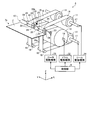
- FIG. 2 is a perspective view showing the banknote storage device of the embodiment.
- FIG. 3 is a perspective view showing a rotation shaft provided with a pulley and a transport roller in the banknote storage device of the embodiment.
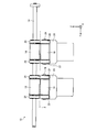
- FIG. 4 is a front view showing a rotation shaft provided with a pulley and a conveyance roller from the conveyance direction of the banknote in the banknote accommodation apparatus of the embodiment.
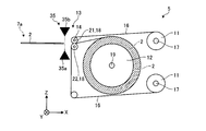
- FIG. 5A is a side view schematically showing an initial state of the winding drum of the banknote storage device of the embodiment.
- FIG. 5B is a side view schematically showing a state in which the banknote is wound on the winding drum of the banknote storage device of the embodiment.
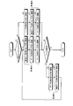
- FIG. 6 is a flowchart for explaining an operation of eliminating a jam that occurs when a bill is fed out in the bill storage device of the embodiment.
- FIG. 7 is a flowchart for explaining an operation for eliminating a jam that occurs during winding of a banknote in the banknote storage device of the embodiment.
- FIG. 1 is a mimetic diagram showing the whole bill handling device containing the bill storage device of an example.
- the banknote handling apparatus 1 includes a deposit / withdrawal unit 3 that deposits / withdraws banknotes 2, a discrimination unit 4 that identifies authenticity of banknotes 2 deposited in the deposit / withdrawal unit 3, A temporary storage unit 5 for temporarily storing the banknotes 2 conveyed from the discrimination unit 4.
- the banknote handling apparatus 1 includes a plurality of storage units 6 that store the banknotes 2 sent from the temporary storage unit 5, a transport mechanism 7 that transports the banknotes 2, and the units 3, 4, 5, 6, and 7. And a control unit 8 for controlling.
- the transport mechanism 7 includes a transport path 7 a that transports the banknote 2 between the units 3, 4, 5, and 6.
- the temporary storage part 5 incorporated in such a banknote handling apparatus 1 corresponds to the banknote storage apparatus of the embodiment.
- the banknote 2 is used as an example of paper sheets, it is not limited to a banknote. Paper sheets also include securities such as bills, checks, gift certificates, various securities, and stock certificates.
- FIG. 2 is a perspective view showing the banknote storage device of the embodiment.
- FIG. 3 is a perspective view showing a rotation shaft provided with a pulley and a transport roller in the banknote storage device of the embodiment.
- FIG. 4 is a front view showing a rotation shaft provided with a pulley and a conveyance roller from the conveyance direction of the banknote in the banknote accommodation apparatus of the embodiment.
- the banknote storage device 5 of the embodiment has two sets of supply reels 11, a winding drum 12, a carry-in / out unit 13, and a rotating shaft 14.
- the direction in which the banknote 2 enters and exits the carry-in / out section 13 is the X direction
- the axial direction of the take-up drum 12 is the Y direction
- the vertical direction of the banknote storage device 5 shown in FIG. It is called a direction.
- the X, Y, and Z directions are shown as in FIG.
- Each supply reel 11 supplies a tape 16 as a wound strip.
- the two supply reels 11 arranged below the take-up drum 12 are supported on a common reel shaft 17 and have a predetermined interval in the axial direction of the take-up drum 12. Are arranged.
- the two supply reels 11 disposed above the winding drum 12 are supported on a common reel shaft 17 and are disposed at a predetermined interval in the axial direction of the winding drum 12. .
- a traveling path of the tape 16 is formed between each supply reel 11 and the winding drum 12, and a plurality of pulleys 18 are arranged on the traveling path of the tape 16.
- Each pulley 18 is rotatably supported by a support shaft or the like, and supports the tape 16 so as to be movable along the travel path.
- Each supply reel 11 is supported on a reel shaft 17 via a torque limiter (not shown), and the tension generated on the tape 16 is restricted to a predetermined tension or less.
- the take-up drum 12 is supported by the support shaft 19.
- the banknote 2 is wound around the winding drum 12 together with the tape 16 supplied from each supply reel 11. Specifically, each banknote 2 is sandwiched between two tapes 16 sent through the upper part of the take-up drum 12 and two tapes 16 sent through the lower part of the take-up drum 12. In a state where the banknote 2 is held between the tapes 16, the banknotes 2 are wound around the winding drum 12 together with the tape 16.
- the carry-in / out unit 13 is provided adjacent to the conveyance path 7 a, and the banknote 2 is carried in and out between the conveyance path 7 a and the banknote storage device 5.
- the rotary shaft 14 is disposed in the carry-in / out section 13, and a plurality of pulleys 18 that support the tape 16 are rotatably provided, and a plurality of transport rollers 21 that transport the banknote 2 to the winding drum 12. It is fixed.
- a drive transmission member 23 such as a pulley on which a driving belt is hung is fixed to one end of the rotating shaft 14 in order to rotationally drive the rotating shaft 14 by a roller driving mechanism 33 described later.
- the pulley 18 is rotatably supported on the rotating shaft 14 via a bearing member (not shown) such as a bearing.
- the conveyance rollers 21 are respectively arranged adjacent to both sides of the pulley 18 in the axial direction (Y direction) of the rotary shaft 14.
- the diameter of the conveying roller 21 is set to be slightly larger than the diameter of the pulley 18, for example.
- a rubber roller is used as the transport roller 21.
- the carry-in / out unit 13 includes pulleys at positions facing each other in the Z direction so as to be paired with the pulleys 18 and the transport rollers 21 supported by the rotating shaft 14.
- 18 and a driven roller 22 are provided.
- the pulley 18 and the driven roller 22 are rotatably supported by the support shaft 24 via a bearing member (not shown) such as a bearing.
- a support stay 25 is fixed in the vicinity of the carry-in / out unit 13, and both ends of the support shaft 24 are supported by the support stay 25.
- the driven roller 22 rotates with the transport roller 21 as the transport roller 21 rotates.
- the rotary shaft 14 is rotated in the A direction so that the banknote 2 is taken up.
- the conveying roller 21 is rotated in the winding direction (hereinafter referred to as the winding direction).
- the rotating shaft 14 is rotated in the B direction when the banknote 2 wound up on the winding drum 12 is unloaded from the loading / unloading unit 13, thereby rotating the banknote 2 from the winding drum 12 (hereinafter, referred to as “rolling drum 12”).
- the conveying roller 21 is rotated in the feeding direction).
- the rotating shaft 14 provided with the pulley 18 and the conveying roller 21 forms a pair. You may comprise with two rotating shafts. Further, in the embodiment, the rotating shaft 14 that supports the conveying roller 21 and the support stay 25 that supports the driven roller 22 below are disposed above in the vertical direction (Z direction), but this configuration is limited. It may not be a thing and may be arranged upside down.
- the narrow tape 16 is used as an example of the belt-like material, but the embodiment is not limited to the tape. Moreover, in the Example, although the tape 16 which consists of a resin film is used, it does not limit to this, The tape which consists of another material may be used as needed.
- the bill storage device 5 includes a reel driving mechanism 31 that rotates the supply reel 11, a drum driving mechanism 32 that rotates the winding drum 12, and a transport roller via the rotating shaft 14. And a roller driving mechanism 33 that rotationally drives the motor 21.
- the reel drive mechanism 31, the drum drive mechanism 32, and the roller drive mechanism 33 are electrically connected to the control unit 8, respectively.
- the reel driving mechanism 31 and the drum driving mechanism 32 have different rotational speeds, and perform a winding operation and a feeding operation in a state where a certain tension is applied to the tape 16.
- the roller driving mechanism 33 is driven in conjunction with the transport mechanism 7 that drives the transport path 7a.
- the reel drive mechanism 31 and the roller drive mechanism 33 are driven by a common drive motor (not shown) and are configured to be individually reversible via a switching gear or the like.
- the reel drive mechanism 31 and the roller drive mechanism 33 may each be driven by an independent drive motor.
- the roller drive mechanism 33 may be driven by a drive motor that drives the transport mechanism 7.
- the banknote storage device 5 has a position sensor 35 as a detection unit that detects the banknote 2.
- the position sensor 35 is disposed in the vicinity of the rotating shaft 14 and detects the banknote 2 passing through the carry-in / out unit 13.
- the position sensor 35 is connected to the control unit 8.
- the control unit 8 controls the reel driving mechanism 31, the drum driving mechanism 32, and the roller driving mechanism 33 based on the detection result of the position sensor 35.
- the position sensor 35 is disposed in the vicinity of the carry-in / out section 13 where the banknote 2 enters and exits the banknote storage device 5.
- the position sensor 35 includes, for example, a light emitting unit 35a that emits detection light and a light receiving unit 35b that receives the detection light emitted from the light emitting unit 35a, as illustrated in FIGS. 2, 5A, and 5B.
- the light emitting unit 35a and the light receiving unit 35b are arranged to face each other in the thickness direction (Z direction) of the banknote 2 passing through the carry-in / out unit 13, but the configuration is not limited thereto.
- the light emitting unit 35 a and the light receiving unit 35 b may be arranged on the same plane along the conveyance direction of the banknote 2.
- the light emission part 35a and the light-receiving part 35b are each arrange
- An optical member (not shown) that reflects and guides light and reflects detection light to the light receiving unit 35b may be disposed.
- the position sensor 35 is disposed on the side opposite to the winding drum 12 with respect to the rotary shaft 14, that is, on the side of the transport path 7 a that transports the banknote 2 to the banknote storage device 5. You may arrange
- control unit 8 When the control unit 8 does not detect the banknote 2 by the position sensor 35 when a predetermined time has elapsed from the start of the operation of feeding the banknote 2 from the winding drum 12 or the operation of winding the banknote 2 on the winding drum 12, and the position When the detection state of the banknote 2 is continued for a predetermined time by the sensor 35, it is determined that the jam of the banknote 2 has occurred. When it is determined that the banknote 2 has jammed, the control unit 8 controls the reel driving mechanism 31, the drum driving mechanism 32, and the roller driving mechanism 33 to rotate only one of the transport roller 21 and the pulley 18. Rotate around the shaft 14.
- control unit 8 drives the reel driving mechanism 31 and the drum driving mechanism 32 so that the tape 16 is wound around the winding drum 12 (winding direction) or the tape wound around the winding drum 12.
- the tape 16 is fed in a direction in which 16 is fed out (feeding direction), and the pulley 18 is rotated with respect to the rotating shaft 14 together with the tape 16.
- control unit 8 drives the roller driving mechanism 33 so that the banknote 2 is wound around the winding drum 12 (winding direction) or the banknote 2 wound around the winding drum 12 is fed out ( The bill 2 is fed in the feeding direction), and the transport roller 21 is rotated together with the rotating shaft 14.
- the banknote accommodating apparatus 5 of a present Example is comprised so that the banknote 2 may be wound around the winding drum 12 using the tape 16 supplied from two sets of upper and lower supply reels 11 located in a line with the winding drum 12 in the axial direction.
- the number of tapes 16 is not limited.
- the banknote storage device 5 may be configured to wind the banknote 2 around the take-up drum 12 using a tape 16 supplied from a pair of upper and lower supply reels 11.
- FIG. 5A is a side view schematically showing an initial state of the winding drum 12 of the banknote storage device 5 of the embodiment.
- Drawing 5B is a side view showing typically the state where bill 2 was wound up by winding drum 12 of bill storage device 5 of an example.
- the banknote storage device 5 is shown in FIG. 5B as the banknote 2 is wound around the winding drum 12 together with the tape 16 from the initial state where the banknote 2 is not wound around the winding drum 12. Moreover, the diameter of the entire winding drum 12 gradually increases.
- the banknote 2 carried into the carry-in / out section 13 of the banknote storage device 5 from the conveyance path 7 a passes through the position sensor 35 and is supported by the conveyance roller 21 fixed to the rotary shaft 14. It is sandwiched between the driven roller 22 supported by the support shaft 24 of the stay 25 and sent.
- the banknotes 2 sent by the transport roller 21 and the driven roller 22 are sent while being sandwiched between the tapes 16 supplied from the supply reels 11 and are accommodated along the circumferential direction of the take-up drum 12 together with the tapes 16. .
- FIG. 6 is a flowchart for explaining an operation of eliminating a jam that occurs when the banknote 2 is fed out in the banknote storage device 5 of the embodiment.
- FIG. 7 is a flowchart for explaining an operation of eliminating a jam that occurs when the banknote 2 is wound up in the banknote storage device 5 of the embodiment.
- the control unit 8 determines whether or not the banknote 2 is jammed based on the detection result of the position sensor 35.
- the controller 8 starts the jam clearing operation by driving only one of the transport roller 21 and the pulley 18 around the rotation shaft 14. First, a case where a jam occurs when the banknote 2 wound up on the winding drum 12 is fed out from the banknote storage device 5 will be described.
- the control unit 8 determines whether or not the position sensor 35 continues to detect the banknote 2 as shown in FIG. It is determined whether or not a jam has occurred (step S1).
- the roller driving mechanism 33 rotates the rotation shaft 14 in the B direction (see FIG. 3), thereby feeding the transport roller 21 in the feeding direction. (Step S2).
- control unit 8 drives the tape 16 in the winding direction by the reel driving mechanism 31 and the drum driving mechanism 32 (step S3).
- the control unit 8 rotates the pulley 18 together with the tape 16 around the rotation shaft 14 in the direction A (see FIG. 3).
- the pulley 18 is rotated in the direction opposite to the rotation direction of the transport roller 21 in step S2.
- control unit 8 drives the tape 16 in the feeding direction by the reel driving mechanism 31 and the drum driving mechanism 32 (step S4). Accordingly, the control unit 8 rotates the pulley 18 together with the tape 16 around the rotation shaft 14 in the B direction (see FIG. 3). Accordingly, the pulley 18 is rotated in the direction opposite to the rotation direction of the pulley 18 in step S3.
- the control unit 8 performs the first operation for eliminating the jam as the transport roller 21 in steps S2 to S4 in FIG.
- the pulleys 18 (tape 16) are alternately driven to rotate in opposite directions.
- the control unit 8 performs a first operation to apply a different external force to the banknote 2 that is causing jamming in the vicinity of the carry-in / out unit 13, thereby changing the banknote 2 that is causing jamming and eliminating the jamming. Plan.
- the control unit 8 determines whether or not the jam has been resolved (step S5).
- step S6 the reel driving mechanism 31 and the drum driving mechanism 32 drive the tape 16 in the winding direction (step). S6).
- the control unit 8 rotates the pulley 18 together with the tape 16 around the rotation shaft 14 in the direction A (see FIG. 3).
- control unit 8 rotationally drives the rotation shaft 14 in the B direction (see FIG. 3) by the roller driving mechanism 33, thereby rotating the transport roller 21 in the feeding direction (Step S7). At this time, the conveyance roller 21 is rotated in the direction opposite to the rotation direction of the pulley 18 in step S6.
- control unit 8 drives the tape 16 in the feeding direction by the reel driving mechanism 31 and the drum driving mechanism 32 (step S8). Accordingly, the control unit 8 rotates the pulley 18 together with the tape 16 around the rotation shaft 14 in the B direction (see FIG. 3). Accordingly, the pulley 18 is rotated in the direction opposite to the rotation direction of the pulley 18 in step S6.
- the control unit 8 performs the first operation for clearing the jam in steps S6 to S8 in FIG.
- the pulleys 18 (tape 16) are alternately driven to rotate in opposite directions.
- the control unit 8 performs the first operation, thereby applying a different external force to the banknote 2 that is causing the jam around the winding drum 12 to eliminate the jam.
- the control unit 8 determines whether or not the jam has been resolved (step S5).
- step S5 when the control unit 8 determines that the jam has been eliminated, the jam elimination operation is terminated.
- the control unit 8 drives the tape 16 in the winding direction by the reel driving mechanism 31 and the drum driving mechanism 32 (step S9). .
- the control unit 8 rotates the pulley 18 together with the tape 16 around the rotation shaft 14 in the direction A (see FIG. 3).
- the controller 8 causes the roller driving mechanism 33 to rotationally drive the rotating shaft 14 in the A direction (see FIG. 3), thereby rotating the transport roller 21 in the winding direction (step S10). At this time, the conveyance roller 21 is rotated in the same direction as the rotation direction of the pulley 18 in step S9.
- the control unit 8 performs conveyance in steps S9 and S10 in FIG. 6 as the second operation for eliminating the jam.
- the roller 21 and the pulley 18 (tape 16) are alternately rotated in the same direction.
- the control unit 8 performs the second operation to apply a different external force to the banknote 2 that is causing the jam, thereby changing the banknote 2 to eliminate the jam. That is, when the jam generated when the banknote 2 is fed is not eliminated by the first operation, the control unit 8 attempts to eliminate the jam by performing an operation of winding the banknote 2 around the winding drum 12 as the second operation. .
- step S9 After performing the second operation of step S9 and step S10, the control unit 8 moves to step S2 and repeats the first operation again. Thereafter, in step S5, the first operation and the second operation are alternately repeated until the control unit 8 determines that the jam has been resolved.
- control unit 8 performs control so as to end the jam removal operation when the jam is not resolved, that is, when the jam is not resolved. You may go. Further, after the second operation, the control unit 8 may determine whether or not the jam has been resolved, and may perform control so as to repeat the first operation only when the jam is not resolved.
- step S21 when the banknote 2 is stored in the banknote storage device 5, a case where a jam occurs when the banknote 2 is wound around the winding drum 12 will be described.
- the control unit 8 determines that the jam of the banknote 2 has occurred, as shown in FIG. 7, whether or not the banknote 2 is being detected by the position sensor 35, that is, on the position sensor 35. It is determined whether or not a jam has occurred (step S21).
- control unit 8 determines that a jam has occurred on the position sensor 35
- the control unit 8 drives the tape 16 in the winding direction by the reel driving mechanism 31 and the drum driving mechanism 32 (step S22).
- the control unit 8 rotates the pulley 18 together with the tape 16 around the rotation shaft 14 in the direction A (see FIG. 3).
- the slack of the tape 16 is eliminated.
- the controller 8 causes the roller drive mechanism 33 to rotationally drive the rotating shaft 14 in the B direction (see FIG. 3), thereby rotating the transport roller 21 in the feeding direction (step S23). At this time, the conveyance roller 21 is rotated in a direction opposite to the rotation direction of the pulley 18 in step S22.
- step S23 the control unit 8 once rotates the transport roller 21 in the feeding direction.
- the controller 8 causes the roller drive mechanism 33 to rotationally drive the rotary shaft 14 in the A direction (see FIG. 3), thereby rotating the transport roller 21 in the winding direction (step S24).
- the control part 8 winds up the banknote 2 which raised the jam on the winding drum 12.
- FIG. Therefore, the conveyance roller 21 is rotated in the direction opposite to the rotation direction of the conveyance roller 21 in step S23.
- the control unit 8 performs the first operation for clearing the jam in step S22 to step S24 in FIG. 21 and the pulley 18 (tape 16) are alternately driven to rotate in opposite directions.
- the control unit 8 performs the first operation to apply a different external force to the banknote 2 that is causing jamming in the vicinity of the carry-in / out unit 13, thereby changing the banknote 2 to eliminate the jamming.
- the controller 8 determines whether or not the jam has been resolved (step S25).
- step S21 described above when the control unit 8 determines that a jam has not occurred on the position sensor 35, the jam occurs on the conveyance path 7a for conveying the banknote 2 to the carry-in / out unit 13 of the banknote storage device 5. Will occur. For this reason, in the banknote accommodating apparatus 5, the removal operation
- step S25 when the control unit 8 determines that the jam has been eliminated, the jam elimination operation is terminated.
- the roller driving mechanism 33 rotationally drives the rotating shaft 14 in the B direction (see FIG. 3).
- the conveyance roller 21 is rotationally driven in the feeding direction (step S27).
- control unit 8 drives the tape 16 in the feeding direction by the reel driving mechanism 31 and the drum driving mechanism 32 (step S28). Accordingly, the control unit 8 rotates the pulley 18 together with the tape 16 around the rotation shaft 14 in the B direction (see FIG. 3). At this time, the pulley 18 is rotated in the same direction as the rotation direction of the transport roller 21 in step S27.
- the control unit 8 performs the second operation for eliminating the jam in steps S27 and S28 in FIG.
- the conveying roller 21 and the pulley 18 (tape 16) are alternately rotated in the same direction.
- the control unit 8 performs the second operation to apply a different external force to the banknote 2 that is causing the jam, thereby changing the banknote 2 to eliminate the jam. That is, when the jam generated when winding the banknote 2 is not eliminated by the first operation, the control unit 8 attempts to eliminate the jam by performing an operation of feeding the banknote 2 from the winding drum 12 as the second operation. .
- step S27 and step S28 After performing the second operation of step S27 and step S28, the control unit 8 moves to step S22 and repeats the first operation again. Thereafter, in step S25, the first operation and the second operation are alternately repeated until the control unit 8 determines that the jam has been resolved.
- the control unit 8 In the jam clearing operation when the banknote 2 is wound up, after the first operation and the second operation are repeated a predetermined number of times, the control unit 8 does not determine that the jam has been resolved, that is, the jam is resolved. If not, control may be performed to end the jam clearing operation. Further, after the second operation, the control unit 8 may determine whether or not the jam has been resolved, and may perform control so as to repeat the first operation only when the jam is not resolved.
- the control method of the banknote storage device 5 configured as described above is a pulley that is arranged in the carry-in / out section 13 where the banknote 2 is carried into and out of the banknote storage device 5 and supports the tape 16 supplied from the supply reel 11.
- a rotating shaft 14 on which a transport roller 21 that transports the banknote 2 is fixed to a winding drum 12 around which the banknote 2 is wound together with the tape 16 is used.
- the banknote 2 is detected by the position sensor 35 that detects the banknote 2 when a predetermined time has elapsed since the start of the operation of feeding the banknote 2 from the winding drum 12 or the operation of winding the banknote 2 onto the winding drum 12.
- the position sensor 35 detects the banknote 2 when a predetermined time has elapsed since the start of the operation of feeding the banknote 2 from the winding drum 12 or the operation of winding the banknote 2 onto the winding drum 12.
- the banknote storage device 5 of the embodiment has a rotation shaft 14 disposed in the carry-in / out section 13, and a pulley 18 that supports the tape 16 is rotatably provided on the rotation shaft 14 and conveys the banknote 2. 21 is fixed. Thereby, it avoids that the gap
- the banknote storage device 5 can increase the probability of canceling a jam that occurs when the banknote 2 is fed and taken up, so that the reliability of the jam clearing operation can be improved.
- the banknote storage device 5 in the embodiment includes a control unit 8 that controls the reel drive mechanism 31, the drum drive mechanism 32, and the roller drive mechanism 33 based on the detection result of the position sensor 35.
- the control unit 8 does not detect the banknote 2 by the position sensor 35 when a predetermined time has elapsed from the start of the operation of feeding the banknote 2 from the winding drum 12 or the operation of winding the banknote 2 on the winding drum 12, and the position
- the reel driving mechanism 31, the drum driving mechanism 32, and the roller driving mechanism 33 are controlled so that only one of the transport roller 21 and the pulley 18 is rotated. Rotate around 14 Thereby, a jam can be smoothly eliminated by giving a change to the banknote 2 in a jam state.
- control part 8 which the banknote accommodating apparatus 5 has performs the 1st operation
- the control unit 8 included in the banknote storage device 5 rotates the conveyance roller 21 and the pulley 18 alternately in opposite directions, and then further turns either the conveyance roller 21 or the pulley 18. It is rotated in the direction opposite to the direction of rotation rotated in the reverse direction. Thereby, it becomes possible to give a change effectively to the banknote 2 in a jam state, and a jam can be eliminated smoothly.
- control part 8 which the banknote accommodating apparatus 5 has is the 2nd which drives the conveyance roller 21 and the pulley 18 alternately in the same direction mutually, when the detection state of the banknote 2 continues by the position sensor 35 after 1st operation
- the conveyance roller 21 in the 1st operation
- the banknotes 2 are fed out from the take-up drum 12 and the slack of the tape 16 around the take-up drum 12 is eliminated, so that a jam occurring around the take-up drum 12 can be eliminated smoothly.
- control part 8 which the banknote accommodating apparatus 5 has performs 1st operation
- Banknote handling device 2 Banknotes (paper sheets) 5 Banknote storage device (temporary storage unit) 8 Control part 11 Supply reel 12 Winding drum 13 Loading / unloading part 14 Rotating shaft 16 Tape (band-like material) 18 Pulley 21 Conveying roller 31 Reel drive mechanism 32 Drum drive mechanism 33 Roller drive mechanism 35 Position sensor (detection unit)
Landscapes
- Engineering & Computer Science (AREA)
- Mechanical Engineering (AREA)
- Physics & Mathematics (AREA)
- General Physics & Mathematics (AREA)
- Discharge By Other Means (AREA)
- Delivering By Means Of Belts And Rollers (AREA)
- Feeding Of Articles By Means Other Than Belts Or Rollers (AREA)
Abstract
紙葉類収容装置(5)は、巻回された帯状材(16)を供給する供給リール(11)と、供給リール(11)から供給された帯状材(16)と共に紙葉類(2)が巻き付けられる巻取ドラム(12)と、紙葉類(2)が搬入出される搬入出部(13)と、搬入出部(13)に配置され、帯状材(16)を支持するプーリ(18)が回転自在に設けられると共に、紙葉類(2)を搬送する搬送ローラ(21)が固定された回転軸(14)と、を有する。
Description
本発明は、紙葉類収容装置及び紙葉類収容装置の制御方法に関する。
ATM(Automated Teller Machine)が有する紙幣取扱装置は、入金された紙幣を一時的に収容する紙幣収容装置を含む。この種の紙幣収容装置としては、供給リールから供給されたテープと共に紙幣を巻き取りドラムに巻き付けることによって、紙幣を収容する構成が知られている。
ところで、上述した紙幣収容装置では、搬送ローラによって紙幣が搬送される搬送路と、紙幣収容装置とが分離しており、搬送路と、搬送路から紙幣収容装置内に紙幣が搬入出される搬入出部との間に間隙が生じていた。このため、紙幣収容装置では、紙幣の巻取り時及び繰出し時に、紙幣が詰まる紙詰まり(以下、ジャムと称する)が発生したときに、搬送路と搬入出部との間隙に紙幣がとどまる場合があった。この間隙に紙幣がとどまった場合には、搬送路の搬送ローラや、紙幣収容装置のテープで紙幣を移動させることが難しく、ジャムを解消することが困難であった。また、紙幣収容装置では、ジャムを解消するときに、ジャムを起こした紙幣に無理な力が加わることや、ジャムを起こした紙幣にテープが巻き込まれることで、紙幣やテープを破損するおそれもあった。
開示の技術は、上記に鑑みてなされたものであって、紙葉類のジャムの解消動作の信頼性を高めることができる紙葉類収容装置及び紙葉類収容装置の制御方法を提供することを目的とする。
本願の開示する紙葉類収容装置の一態様は、巻回された帯状材を供給する供給リールと、前記供給リールから供給された前記帯状材と共に紙葉類が巻き付けられる巻取ドラムと、前記紙葉類が搬入出される搬入出部と、前記搬入出部に配置され、前記帯状材を支持するプーリが回転自在に設けられると共に、前記紙葉類を搬送する搬送ローラが固定された回転軸と、を有する。
本願の開示する紙葉類収容装置の一態様によれば、紙葉類のジャムの解消動作の信頼性を高めることができる。
以下に、本願の開示する紙葉類収容装置及び紙葉類収容装置の制御方法の実施例を図面に基づいて詳細に説明する。なお、以下の実施例によって、本願の開示する紙葉類収容装置及び紙葉類収容装置の制御方法が限定されるものではない。
[紙幣取扱装置の構成]
図1は、実施例の紙幣収容装置を含む紙幣取扱装置全体を示す模式図である。図1に示すように、実施例に係る紙幣取扱装置1は、紙幣2を入出金する入出金部3と、入出金部3に入金された紙幣2の真贋等を鑑別する鑑別部4と、鑑別部4から搬送された紙幣2を一時的に収容する一時収容部5と、を備える。また、紙幣取扱装置1は、一時収容部5から送られた紙幣2を格納する複数の格納部6と、紙幣2を搬送する搬送機構7と、各部3、4、5、6、7をそれぞれ制御する制御部8と、を備える。搬送機構7は、各部3、4、5、6の間で紙幣2を搬送する搬送路7aを有する。このような紙幣取扱装置1に組み込まれた一時収容部5が、実施例の紙幣収容装置に相当する。本実施例では、紙葉類の一例として紙幣2を用いるが、紙幣に限定するものではない。紙葉類には、例えば、手形、小切手、商品券、各種証券、株券等の有価証券も含まれる。
図1は、実施例の紙幣収容装置を含む紙幣取扱装置全体を示す模式図である。図1に示すように、実施例に係る紙幣取扱装置1は、紙幣2を入出金する入出金部3と、入出金部3に入金された紙幣2の真贋等を鑑別する鑑別部4と、鑑別部4から搬送された紙幣2を一時的に収容する一時収容部5と、を備える。また、紙幣取扱装置1は、一時収容部5から送られた紙幣2を格納する複数の格納部6と、紙幣2を搬送する搬送機構7と、各部3、4、5、6、7をそれぞれ制御する制御部8と、を備える。搬送機構7は、各部3、4、5、6の間で紙幣2を搬送する搬送路7aを有する。このような紙幣取扱装置1に組み込まれた一時収容部5が、実施例の紙幣収容装置に相当する。本実施例では、紙葉類の一例として紙幣2を用いるが、紙幣に限定するものではない。紙葉類には、例えば、手形、小切手、商品券、各種証券、株券等の有価証券も含まれる。
[紙幣収容装置の構成]
図2は、実施例の紙幣収容装置を示す斜視図である。図3は、実施例の紙幣収容装置において、プーリ及び搬送ローラが設けられた回転軸を示す斜視図である。図4は、実施例の紙幣収容装置において、プーリ及び搬送ローラが設けられた回転軸を紙幣の搬送方向から示す正面図である。
図2は、実施例の紙幣収容装置を示す斜視図である。図3は、実施例の紙幣収容装置において、プーリ及び搬送ローラが設けられた回転軸を示す斜視図である。図4は、実施例の紙幣収容装置において、プーリ及び搬送ローラが設けられた回転軸を紙幣の搬送方向から示す正面図である。
図2に示すように、実施例の紙幣収容装置5は、二組の供給リール11と、巻取ドラム12と、搬入出部13と、回転軸14と、を有する。図2において、説明の便宜上、搬入出部13に対して紙幣2が出入りする方向をX方向、巻取ドラム12の軸方向をY方向、図2に示した紙幣収容装置5の上下方向をZ方向と称する。図3以降においても、図2と同様にX、Y、Z方向を示す。
各供給リール11は、巻回された帯状材としてのテープ16を供給する。二組の供給リール11において、巻取ドラム12の下方に配置される2つの供給リール11は、共通のリール軸17上に支持されており、巻取ドラム12の軸方向に所定の間隔をあけて配置されている。同様に、巻取ドラム12の上方に配置される2つの供給リール11は、共通のリール軸17上に支持されており、巻取ドラム12の軸方向に所定の間隔をあけて配置されている。各供給リール11から巻取ドラム12までの間には、テープ16の走行経路が構成されており、テープ16の走行経路上に複数のプーリ18が配置されている。各プーリ18は、支軸等に回転自在に支持されており、テープ16を走行経路に沿って移動自在に支持している。また、各供給リール11は、リール軸17にトルクリミッタ(図示せず)を介して支持されており、テープ16に生じる張力が所定の張力以下に規制されている。
巻取ドラム12は、支軸19に支持されている。巻取ドラム12には、各供給リール11から供給されたテープ16と共に紙幣2が巻き付けられる。詳細には、巻取ドラム12の上方を通って送られた2つのテープ16と、巻取ドラム12の下方を通って送られた2つのテープ16との間に紙幣2を挟み込むことで、各テープ16間に紙幣2が保持された状態で、テープ16と共に紙幣2が巻取ドラム12に巻き付けられる。
搬入出部13は、図1に示すように、搬送路7aに隣接して設けられており、搬送路7aと紙幣収容装置5との間で紙幣2が搬入出される。回転軸14は、搬入出部13に配置されており、テープ16を支持する複数のプーリ18が回転自在に設けられると共に、巻取ドラム12に対して紙幣2を搬送する複数の搬送ローラ21が固定されている。また、回転軸14の一端には、後述するローラ駆動機構33によって回転軸14を回転駆動するために、例えば駆動ベルトが掛けられるプーリ等の駆動伝達部材23が固定されている。
プーリ18は、例えばベアリング等の軸受部材(図示せず)を介して、回転軸14に回転自在に支持されている。搬送ローラ21は、回転軸14の軸方向(Y方向)におけるプーリ18の両側に隣接してそれぞれ配置されている。搬送ローラ21の直径は、例えばプーリ18の直径よりもやや大きく設定されている。搬送ローラ21としては、例えばゴムローラが用いられている。
また、搬入出部13には、図3及び図4に示すように、回転軸14に支持された各プーリ18及び搬送ローラ21とそれぞれ対をなすように、Z方向において対向する位置に、プーリ18及び従動ローラ22がそれぞれ設けられている。プーリ18及び従動ローラ22は、例えばベアリング等の軸受部材(図示せず)を介して、支軸24に回転自在に支持されている。搬入出部13近傍には、支持ステー25が固定されており、支持ステー25に、支軸24の両端が支持されている。従動ローラ22は、搬送ローラ21が回転することで、搬送ローラ21と連れまわりする。
また、回転軸14は、図3に示すように、搬入出部13から搬入された紙幣2を巻取ドラム12へ巻き取る場合、A方向に回転されることで、紙幣2を巻取ドラム12に巻き取る方向(以下、巻き取り方向と称する)に搬送ローラ21が回転される。一方、回転軸14は、巻取ドラム12に巻き取られた紙幣2を搬入出部13から搬出する場合、B方向に回転されることで、紙幣2を巻取ドラム12から繰り出す方向(以下、繰り出し方向と称する)に搬送ローラ21が回転される。
なお、実施例では、プーリ18及び搬送ローラ21が設けられた回転軸14を1つのみ有して構成されたが、プーリ18及び搬送ローラ21が設けられた回転軸14が対をなすように2つの回転軸を有して構成されてもよい。また、実施例では、上下方向(Z方向)における上方に搬送ローラ21を支持する回転軸14が配置され、下方に従動ローラ22を支持する支持ステー25が配置されたが、この構成に限定されるものではなく、上下逆に配置されてもよい。
また、実施例では、帯状材の一例として幅狭なテープ16を用いるが、テープに限定するものではない。また、実施例では、樹脂フィルムからなるテープ16が用いられるが、これに限定するものではなく、必要に応じて他の材料からなるテープが用いられてもよい。
また、図2に示すように、紙幣収容装置5は、供給リール11を回転駆動するリール駆動機構31と、巻取ドラム12を回転駆動するドラム駆動機構32と、回転軸14を介して搬送ローラ21を回転駆動するローラ駆動機構33と、を有する。リール駆動機構31、ドラム駆動機構32及びローラ駆動機構33は、制御部8にそれぞれ電気的に接続されている。リール駆動機構31とドラム駆動機構32は、回転速度が異なっており、テープ16に一定の張力を付与した状態で巻き取り動作及び繰り出し動作を行う。
また、ローラ駆動機構33は、搬送路7aを駆動する搬送機構7と連動して駆動される。本実施例において、リール駆動機構31とローラ駆動機構33は、共通の駆動モータ(図示せず)によって駆動され、切換ギア等を介して個々に逆転可能に構成されている。なお、この構成に限定されるものではなく、リール駆動機構31とローラ駆動機構33は、それぞれ独立した駆動モータによって駆動されてもよい。また、ローラ駆動機構33は、搬送機構7を駆動する駆動モータによって駆動されてもよい。
また、紙幣収容装置5は、紙幣2を検知する検知部としての位置センサ35を有する。位置センサ35は、回転軸14の近傍に配置されており、搬入出部13を通過する紙幣2を検知する。位置センサ35は、制御部8に接続されている。制御部8は、位置センサ35の検知結果に基づいてリール駆動機構31、ドラム駆動機構32及びローラ駆動機構33を制御する。
実施例では、位置センサ35が、紙幣収容装置5に対して紙幣2が出入りする搬入出部13の近傍に配置されている。位置センサ35は、例えば、図2及び図5A、図5Bに示すように、検知光を発する発光部35aと、発光部35aが発した検知光を受光する受光部35bと、を有する。
実施例において、発光部35aと受光部35bは、搬入出部13を通過する紙幣2の厚み方向(Z方向)において、対向して配置されたが、この構成に限定されるものではない。発光部35aと受光部35bは、例えば、紙幣2の搬送方向に沿う同一面上に配置されてもよい。この構成の場合、搬入出部13を通過する紙幣2の厚み方向における一方側に発光部35a及び受光部35bがそれぞれ配置され、紙幣2の厚み方向における他方側に、発光部35aが発した検知光を反射及び導光して受光部35bへ検出光を反射する光学部材(図示せず)が配置されてもよい。
また、位置センサ35は、回転軸14に対して巻取ドラム12とは反対側、すなわち紙幣収容装置5に紙幣2を搬送する搬送路7a側に配置されたが、回転軸14に対して巻取ドラム12側、すなわち紙幣収容装置5の内方へ配置されてもよい。
制御部8は、巻取ドラム12から紙幣2を繰り出す動作または巻取ドラム12に紙幣2を巻き取る動作の開始後から所定時間経過したときに位置センサ35によって紙幣2を検知しない場合、及び位置センサ35によって紙幣2の検知状態が所定時間継続する場合に、紙幣2のジャムが発生したと判断する。制御部8は、紙幣2のジャムが発生したと判断した場合、リール駆動機構31、ドラム駆動機構32及びローラ駆動機構33を制御することで、搬送ローラ21またはプーリ18のいずれか一方のみを回転軸14まわりに回転駆動させる。
すなわち、制御部8は、リール駆動機構31及びドラム駆動機構32を駆動することで、巻取ドラム12にテープ16が巻き取られる方向(巻き取り方向)または巻取ドラム12に巻き取られたテープ16を繰り出す方向(繰り出し方向)にテープ16が送られ、テープ16と共にプーリ18が回転軸14に対して回転される。また、制御部8は、ローラ駆動機構33を駆動することで、巻取ドラム12に紙幣2が巻き取られる方向(巻き取り方向)または巻取ドラム12に巻き取られた紙幣2を繰り出す方向(繰り出し方向)に紙幣2が送られ、搬送ローラ21が回転軸14と共に回転される。
なお、本実施例の紙幣収容装置5は、巻取ドラム12の軸方向に並んだ上下二組の供給リール11から供給されるテープ16を用いて紙幣2を巻取ドラム12に巻き付けるように構成されたが、テープ16の個数を限定するものではない。紙幣収容装置5は、上下一組の供給リール11から供給されるテープ16を用いて紙幣2を巻取ドラム12に巻き付けるように構成されてもよい。
[紙幣の収容動作]
図5Aは、実施例の紙幣収容装置5の巻取ドラム12の初期状態を模式的に示す側面図である。図5Bは、実施例の紙幣収容装置5の巻取ドラム12に紙幣2が巻き取られた状態を模式的に示す側面図である。
図5Aは、実施例の紙幣収容装置5の巻取ドラム12の初期状態を模式的に示す側面図である。図5Bは、実施例の紙幣収容装置5の巻取ドラム12に紙幣2が巻き取られた状態を模式的に示す側面図である。
紙幣収容装置5は、図5Aに示すように、巻取ドラム12に紙幣2が巻き取られていない初期状態から、巻取ドラム12にテープ16と共に紙幣2が巻き付けられるに従って、図5Bに示すように、巻取ドラム12全体の直径が徐々に大きくなる。図5Aに示すように、搬送路7aから、紙幣収容装置5の搬入出部13へ搬入された紙幣2は、位置センサ35を通過しながら、回転軸14に固定された搬送ローラ21と、支持ステー25の支軸24に支持された従動ローラ22とに挟持されて送られる。搬送ローラ21と従動ローラ22によって送られた紙幣2は、各供給リール11から供給されたテープ16の間に挟まれて送られ、テープ16と共に巻取ドラム12の周方向に沿って収容される。
[ジャムの解消動作]
図6は、実施例の紙幣収容装置5において、紙幣2の繰り出し時に生じたジャムを解消する動作を説明するためのフローチャートである。図7は、実施例の紙幣収容装置5において、紙幣2の巻き取り時に生じたジャムを解消する動作を説明するためのフローチャートである。
図6は、実施例の紙幣収容装置5において、紙幣2の繰り出し時に生じたジャムを解消する動作を説明するためのフローチャートである。図7は、実施例の紙幣収容装置5において、紙幣2の巻き取り時に生じたジャムを解消する動作を説明するためのフローチャートである。
制御部8は、上述したように、位置センサ35の検知結果に基づいて紙幣2のジャムが発生しているか否かを判断する。制御部8は、紙幣2のジャムが発生していると判断した場合、搬送ローラ21またはプーリ18のいずれか一方のみを回転軸14まわりに回転駆動させることで、ジャムの解消動作を開始する。まず、巻取ドラム12に巻き取られた紙幣2を、紙幣収容装置5から繰り出すときにジャムが発生した場合について説明する。
制御部8は、紙幣2のジャムが発生していると判断した場合、図6に示すように、位置センサ35による紙幣2の検知状態が継続しているか否か、すなわち、位置センサ35上でジャムが発生しているか否かを判断する(ステップS1)。制御部8は、位置センサ35上でジャムが発生していると判断したとき、ローラ駆動機構33によって回転軸14をB方向(図3参照)に回転駆動することで、搬送ローラ21を繰り出し方向に回転駆動させる(ステップS2)。
紙幣2の繰り出し時にジャムが発生したとき、搬送路7aまで正常に繰り出された紙幣2が紙幣収容装置5内に戻ることを避け、搬送路7a内の紙幣2を搬送させることが好ましい。このため、紙幣2の繰り出し時に位置センサ35上でジャム、つまり搬入出部13近傍でジャムが発生した場合には、ステップS2に示すように、一旦、搬送ローラ21を繰り出し方向に回転させる。
続いて、制御部8は、リール駆動機構31及びドラム駆動機構32によってテープ16を巻き取り方向に駆動する(ステップS3)。これにより、制御部8は、テープ16と共にプーリ18を回転軸14まわりにA方向(図3参照)に回転させる。このとき、プーリ18は、ステップS2における搬送ローラ21の回転方向とは逆方向に回転される。
更に続いて、制御部8は、リール駆動機構31及びドラム駆動機構32によってテープ16を繰り出し方向に駆動する(ステップS4)。これにより、制御部8は、テープ16と共にプーリ18を回転軸14まわりにB方向(図3参照)に回転させる。したがって、プーリ18は、ステップS3におけるプーリ18の回転方向とは逆方向に回転される。
このように紙幣2の繰り出し時に位置センサ35上でジャムが発生している場合、制御部8は、ジャムを解消するための第1動作として、図6中のステップS2~ステップS4において搬送ローラ21及びプーリ18(テープ16)をそれぞれ交互に逆方向に回転駆動させる。制御部8は、第1動作を行うことで、搬入出部13近傍でジャムを起こしている紙幣2に異なる外力を加えることにより、ジャムを起こしている紙幣2に変化を与えて、ジャムの解消を図る。ステップS2~ステップS4の第1動作を行った後、制御部8は、ジャムが解消したか否かを判断する(ステップS5)。
一方、上述したステップS1において、制御部8は、位置センサ35上でジャムが発生していないと判断したとき、リール駆動機構31及びドラム駆動機構32によってテープ16を巻き取り方向に駆動する(ステップS6)。これにより、制御部8は、テープ16と共にプーリ18を回転軸14まわりにA方向(図3参照)に回転させる。
このように位置センサ35上でジャムが発生しておらず、巻取ドラム12の周囲でジャムが発生している場合には、テープ16のたるみを解消することが好ましい。このため、紙幣2の繰り出し時に位置センサ35上でジャムが発生していない場合、つまり巻取ドラム12の周囲でジャムが発生した場合には、制御部8は、一旦、テープ16を巻き取り方向に駆動させる。
続いて、制御部8は、ローラ駆動機構33によって回転軸14をB方向(図3参照)に回転駆動することで、搬送ローラ21を繰り出し方向に回転駆動させる(ステップS7)。このとき、搬送ローラ21は、ステップS6におけるプーリ18の回転方向とは逆方向に回転される。
更に続いて、制御部8は、リール駆動機構31及びドラム駆動機構32によってテープ16を繰り出し方向に駆動する(ステップS8)。これにより、制御部8は、テープ16と共にプーリ18を回転軸14まわりにB方向(図3参照)に回転させる。したがって、プーリ18は、ステップS6におけるプーリ18の回転方向とは逆方向に回転される。
このように紙幣2の繰り出し時に位置センサ35上でジャムが発生していない場合、制御部8は、ジャムを解消するための第1動作として、図6中のステップS6~ステップS8において搬送ローラ21及びプーリ18(テープ16)をそれぞれ交互に逆方向に回転駆動させる。制御部8は、第1動作を行うことで、巻取ドラム12の周囲でジャムを起こしている紙幣2に異なる外力を加えることで、ジャムの解消を図る。ステップS6~ステップS8の第1動作を行った後、制御部8は、ジャムが解消したか否かを判断する(ステップS5)。
上述したステップS5において、制御部8は、ジャムが解消したと判断したとき、ジャムの解消動作を終了する。一方、制御部8は、位置センサ35の検知結果に基づいてジャムが解消していないと判断したとき、リール駆動機構31及びドラム駆動機構32によってテープ16を巻き取り方向に駆動する(ステップS9)。これにより、制御部8は、テープ16と共にプーリ18を回転軸14まわりにA方向(図3参照)に回転させる。
続いて、制御部8は、ローラ駆動機構33によって回転軸14をA方向(図3参照)に回転駆動することで、搬送ローラ21を巻き取り方向に回転駆動させる(ステップS10)。このとき、搬送ローラ21は、ステップS9におけるプーリ18の回転方向とは同一方向に回転される。
このように制御部8は、第1動作後、紙幣2の繰り出し時に発生したジャムが解消されなかった場合、ジャムを解消するための第2動作として、図6中のステップS9及びステップS10において搬送ローラ21及びプーリ18(テープ16)をそれぞれ交互に同一方向に回転駆動させる。制御部8は、第2動作を行うことで、ジャムを起こしている紙幣2に異なる外力を加えることにより、紙幣2に変化を与えて、ジャムの解消を図る。すなわち、紙幣2の繰り出し時に発生したジャムが、第1動作によって解消しない場合、制御部8は、第2動作として、巻取ドラム12に紙幣2を巻き取る動作を行うことでジャムの解消を図る。
ステップS9及びステップS10の第2動作を行った後、制御部8は、ステップS2へ移り、再度、第1動作を繰り返す。以降、ステップS5において、制御部8が、ジャムが解消したと判断するまで、第1動作、第2動作を交互に繰り返す。
なお、第1動作、第2動作を所定の回数だけ繰り返した後、制御部8は、ジャムが解消したと判断しない場合、つまりジャムが解消されない場合、ジャムの解消動作を終了するように制御を行ってもよい。また、第2動作後、制御部8は、ジャムが解消されたか否かを判断し、ジャムが解消されていない場合のみ、第1動作を繰り返すように制御を行ってもよい。
つぎに、紙幣収容装置5に紙幣2を収容する際、巻取ドラム12に紙幣2を巻き取るときにジャムが生じた場合について説明する。制御部8は、紙幣2のジャムが発生していると判断した場合、図7に示すように、位置センサ35による紙幣2の検知状態が継続しているか否か、すなわち、位置センサ35上でジャムが発生しているか否かを判断する(ステップS21)。
制御部8は、位置センサ35上でジャムが発生していると判断したとき、リール駆動機構31及びドラム駆動機構32によってテープ16を巻き取り方向に駆動する(ステップS22)。これにより、制御部8は、テープ16と共にプーリ18を回転軸14まわりにA方向(図3参照)に回転させる。これにより、テープ16のたるみを解消する。
続いて、制御部8は、ローラ駆動機構33によって回転軸14をB方向(図3参照)に回転駆動することで、搬送ローラ21を繰り出し方向に回転駆動させる(ステップS23)。このとき、搬送ローラ21は、ステップS22におけるプーリ18の回転方向とは逆方向に回転される。
紙幣2の巻き取り時にジャムが発生したとき、搬入出部13までの搬送路7a内に紙幣2を戻すスペースが残されている可能性が高く、位置センサ35上でジャムを起こした紙幣2を、搬入出部13から搬送路7a側へ戻すことが好ましい。このため、制御部8は、ステップS23に示すように、一旦、搬送ローラ21を繰り出し方向に回転させる。
更に続いて、制御部8は、ローラ駆動機構33によって回転軸14をA方向(図3参照)に回転駆動することで、搬送ローラ21を巻き取り方向に回転駆動させる(ステップS24)。これにより、制御部8は、ジャムを起こした紙幣2を巻取ドラム12に巻き取る。したがって、搬送ローラ21は、ステップS23における搬送ローラ21の回転方向とは逆方向に回転される。
このように紙幣2の巻き取り時に位置センサ35上でジャムが発生している場合、制御部8は、ジャムを解消するための第1動作として、図7中のステップS22~ステップS24において搬送ローラ21及びプーリ18(テープ16)をそれぞれ交互に逆方向に回転駆動させる。制御部8は、第1動作を行うことで、搬入出部13近傍でジャムを起こしている紙幣2に異なる外力を加えることにより、紙幣2に変化を与えて、ジャムの解消を図る。ステップS22~ステップS24の第1動作を行った後、制御部8は、ジャムが解消したか否かを判断する(ステップS25)。
一方、上述したステップS21において、制御部8は、位置センサ35上でジャムが発生していないと判断したとき、紙幣収容装置5の搬入出部13へ紙幣2を搬送する搬送路7a上でジャムが発生したことになる。このため、紙幣収容装置5では、ジャムの解消動作を行わず、搬送機構7によって搬送路7a上で発生したジャムの解消動作を行う。
上述したステップS25において、制御部8は、ジャムが解消したと判断したとき、ジャムの解消動作を終了する。一方、制御部8は、位置センサ35の検知結果に基づいてジャムが解消していないと判断したとき、ローラ駆動機構33によって回転軸14をB方向(図3参照)に回転駆動することで、搬送ローラ21を繰り出し方向に回転駆動させる(ステップS27)。
続いて、制御部8は、リール駆動機構31及びドラム駆動機構32によってテープ16を繰り出し方向に駆動する(ステップS28)。これにより、制御部8は、テープ16と共にプーリ18を回転軸14まわりにB方向(図3参照)に回転させる。このとき、プーリ18は、ステップS27における搬送ローラ21の回転方向とは同一方向に回転される。
このように制御部8は、第1動作後、紙幣2の巻き取り時に発生したジャムが解消されなかった場合、ジャムを解消するための第2動作として、図7中のステップS27及びステップS28において搬送ローラ21及びプーリ18(テープ16)をそれぞれ交互に同一方向に回転駆動させる。制御部8は、第2動作を行うことで、ジャムを起こしている紙幣2に異なる外力を加えることにより、紙幣2に変化を与えて、ジャムの解消を図る。すなわち、紙幣2の巻き取り時に発生したジャムが、第1動作によって解消しない場合、制御部8は、第2動作として、巻取ドラム12から紙幣2を繰り出す動作を行うことでジャムの解消を図る。
ステップS27及びステップS28の第2動作を行った後、制御部8は、ステップS22へ移り、再度、第1動作を繰り返す。以降、ステップS25において、制御部8が、ジャムが解消したと判断するまで、第1動作、第2動作を交互に繰り返す。
なお、紙幣2の巻取り時のジャムの解消動作においても、第1動作、第2動作を所定の回数だけ繰り返した後、制御部8は、ジャムが解消したと判断しない場合、つまりジャムが解消されない場合、ジャムの解消動作を終了するように制御を行ってもよい。また、第2動作後、制御部8は、ジャムが解消されたか否かを判断し、ジャムが解消されていない場合のみ、第1動作を繰り返すように制御を行ってもよい。
[紙幣収容装置の制御方法]
以上のように構成された紙幣収容装置5の制御方法は、紙幣収容装置5に対して紙幣2が搬入出される搬入出部13に配置され、供給リール11から供給されたテープ16を支持するプーリ18が回転自在に設けられると共に、テープ16と共に紙幣2が巻き付けられる巻取ドラム12に対して紙幣2を搬送する搬送ローラ21が固定された回転軸14を用いる。この制御方法では、巻取ドラム12から紙幣2を繰り出す動作または巻取ドラム12に紙幣2を巻き取る動作の開始後から所定時間経過したときに紙幣2を検知する位置センサ35によって紙幣2を検知しない場合、及び位置センサ35によって紙幣2の検知状態が所定時間継続する場合に、搬送ローラ21またはプーリ18のいずれか一方のみを回転軸14まわりに回転駆動させる。
以上のように構成された紙幣収容装置5の制御方法は、紙幣収容装置5に対して紙幣2が搬入出される搬入出部13に配置され、供給リール11から供給されたテープ16を支持するプーリ18が回転自在に設けられると共に、テープ16と共に紙幣2が巻き付けられる巻取ドラム12に対して紙幣2を搬送する搬送ローラ21が固定された回転軸14を用いる。この制御方法では、巻取ドラム12から紙幣2を繰り出す動作または巻取ドラム12に紙幣2を巻き取る動作の開始後から所定時間経過したときに紙幣2を検知する位置センサ35によって紙幣2を検知しない場合、及び位置センサ35によって紙幣2の検知状態が所定時間継続する場合に、搬送ローラ21またはプーリ18のいずれか一方のみを回転軸14まわりに回転駆動させる。
実施例の紙幣収容装置5は、搬入出部13に配置された回転軸14を有し、回転軸14に、テープ16を支持するプーリ18が回転自在に設けられると共に紙幣2を搬送する搬送ローラ21が固定されている。これにより、関連技術のように搬送機構7の搬送路7aと紙幣収容装置5との連結部分に紙幣2の搬送が困難な間隙、すなわち紙幣2が搬送ローラ21に到達しない範囲が生じることを避けることができる。また、紙幣収容装置5では、搬送ローラ21及びプーリ18が回転軸14まわりにそれぞれ独立して回転駆動可能になることで、互いに逆方向に回転させることが可能になるので、ジャム状態の紙幣2に変化を与えやすい。その結果、紙幣収容装置5は、紙幣2の繰り出し時及び巻き取り時に発生したジャムを解消する確率が高められるので、ジャムの解消動作の信頼性を高めることができる。
また、実施例における紙幣収容装置5は、位置センサ35の検知結果に基づいてリール駆動機構31、ドラム駆動機構32及びローラ駆動機構33を制御する制御部8を有する。制御部8は、巻取ドラム12から紙幣2を繰り出す動作または巻取ドラム12に紙幣2を巻き取る動作の開始後から所定時間経過したときに位置センサ35によって紙幣2を検知しない場合、及び位置センサ35によって紙幣2の検知状態が所定時間継続する場合に、リール駆動機構31、ドラム駆動機構32及びローラ駆動機構33を制御することで、搬送ローラ21またはプーリ18のいずれか一方のみを回転軸14まわりに回転駆動させる。これにより、ジャム状態の紙幣2に変化を与えることで、ジャムをスムースに解消することができる。
また、紙幣収容装置5が有する制御部8は、搬送ローラ21及びプーリ18を互いに逆方向に交互に回転駆動させる第1動作を行う。これにより、ジャム状態の紙幣2に変化を効果的に与えることが可能になり、ジャムをスムースに解消することができる。
また、紙幣収容装置5が有する制御部8は、第1動作において、搬送ローラ21及びプーリ18をそれぞれ逆方向に交互に回転駆動させた後、更に搬送ローラ21またはプーリ18のいずれか一方を、逆方向に回転駆動させた回転方向とは逆方向へ回転駆動させる。これにより、ジャム状態の紙幣2に変化を効果的に与えることが可能になり、ジャムをスムースに解消することができる。
また、紙幣収容装置5が有する制御部8は、第1動作後、位置センサ35によって紙幣2の検知状態が継続する場合、搬送ローラ21及びプーリ18を互いに同一方向に交互に回転駆動させる第2動作を行う。これにより、第1動作でジャムが解消されなかった場合であっても、ジャム状態の紙幣2に変化を効果的に与えることが可能になり、ジャムをスムースに解消することができる。
また、紙幣収容装置5では、制御部8により、第1動作において、制御部8により、搬送ローラ21が、巻取ドラム12から紙幣2を繰り出す方向へ回転駆動され、プーリ18が、巻取ドラム12にテープ16を巻き取る方向へ回転駆動される。これにより、巻取ドラム12から紙幣2を繰り出すと共に巻取ドラム12の周囲でのテープ16のたるみが解消され、巻取ドラム12の周囲で発生したジャムをスムースに解消することができる。
また、紙幣収容装置5が有する制御部8は、第2動作後、第1動作を再度行う。これにより、ジャム状態の紙幣2に繰り返し変化を与えることで、ジャムを解消する確率が高められ、ジャムの解消動作の信頼性を高めることが可能になる。
1 紙幣取扱装置
2 紙幣(紙葉類)
5 紙幣収容装置(一時収容部)
8 制御部
11 供給リール
12 巻取ドラム
13 搬入出部
14 回転軸
16 テープ(帯状材)
18 プーリ
21 搬送ローラ
31 リール駆動機構
32 ドラム駆動機構
33 ローラ駆動機構
35 位置センサ(検出部)
2 紙幣(紙葉類)
5 紙幣収容装置(一時収容部)
8 制御部
11 供給リール
12 巻取ドラム
13 搬入出部
14 回転軸
16 テープ(帯状材)
18 プーリ
21 搬送ローラ
31 リール駆動機構
32 ドラム駆動機構
33 ローラ駆動機構
35 位置センサ(検出部)
Claims (8)
- 巻回された帯状材を供給する供給リールと、
前記供給リールから供給された前記帯状材と共に紙葉類が巻き付けられる巻取ドラムと、
前記紙葉類が搬入出される搬入出部と、
前記搬入出部に配置され、前記帯状材を支持するプーリが回転自在に設けられると共に、前記紙葉類を搬送する搬送ローラが固定された回転軸と、
を有する、紙葉類収容装置。 - 前記供給リールを回転駆動するリール駆動機構と、
前記巻取ドラムを回転駆動するドラム駆動機構と、
前記回転軸を介して前記搬送ローラを回転駆動するローラ駆動機構と、
前記回転軸の近傍に配置され、前記紙葉類を検知する検知部と、
前記検知部の検知結果に基づいて前記リール駆動機構、前記ドラム駆動機構及び前記ローラ駆動機構を制御する制御部と、を更に有し、
前記制御部は、前記巻取ドラムから前記紙葉類を繰り出す動作または前記巻取ドラムに前記紙葉類を巻き取る動作の開始後から所定時間経過したときに前記検知部によって前記紙葉類を検知しない場合、及び前記検知部によって前記紙葉類の検知状態が所定時間継続する場合に、前記リール駆動機構、前記ドラム駆動機構及び前記ローラ駆動機構を制御することで、前記搬送ローラまたは前記プーリのいずれか一方のみを前記回転軸まわりに回転駆動させる、
請求項1に記載の紙葉類収容装置。 - 前記制御部は、前記搬送ローラ及び前記プーリを互いに逆方向に交互に回転駆動させる第1動作を行う、
請求項2に記載の紙葉類収容装置。 - 前記第1動作において、前記制御部は、前記搬送ローラ及び前記プーリをそれぞれ前記逆方向に交互に回転駆動させた後、更に前記搬送ローラまたは前記プーリのいずれか一方を、前記逆方向に回転駆動させた回転方向とは逆方向へ回転駆動させる、請求項3に記載の紙葉類収容装置。
- 前記第1動作後、前記制御部は、前記検知部によって前記紙葉類の検知状態が継続する場合、前記搬送ローラ及び前記プーリを互いに同一方向に交互に回転駆動させる第2動作を行う、
請求項4に記載の紙葉類収容装置。 - 前記第1動作において、
前記搬送ローラは、前記巻取ドラムから前記紙葉類を繰り出す方向へ回転駆動され、
前記プーリは、前記巻取ドラムに前記帯状材を巻き取る方向へ回転駆動される、
請求項3に記載の紙葉類収容装置。 - 前記制御部は、前記第2動作後、前記第1動作を再度行う、
請求項5に記載の紙葉類収容装置。 - 紙幣収容装置に対して紙葉類が搬入出される搬入出部に配置され、供給リールから供給された帯状材を支持するプーリが回転自在に設けられると共に、前記帯状材と共に前記紙葉類が巻き付けられる巻取ドラムに対して前記紙葉類を搬送する搬送ローラが固定された回転軸を用いて、
前記巻取ドラムから前記紙葉類を繰り出す動作または前記巻取ドラムに前記紙葉類を巻き取る動作の開始後から所定時間経過したときに前記紙葉類を検知する検知部によって前記紙葉類を検知しない場合、及び前記検知部によって前記紙葉類の検知状態が所定時間継続する場合に、前記搬送ローラまたは前記プーリのいずれか一方のみを前記回転軸まわりに回転駆動させる、
紙葉類収容装置の制御方法。
Priority Applications (4)
| Application Number | Priority Date | Filing Date | Title |
|---|---|---|---|
| PCT/JP2016/065816 WO2017203715A1 (ja) | 2016-05-27 | 2016-05-27 | 紙葉類収容装置及び紙葉類収容装置の制御方法 |
| JP2018518934A JP6539412B2 (ja) | 2016-05-27 | 2016-05-27 | 紙葉類収容装置及び紙葉類収容装置の制御方法 |
| CN201680085620.7A CN109155092B (zh) | 2016-05-27 | 2016-05-27 | 纸张容纳设备和控制纸张容纳设备的方法 |
| US16/185,507 US10618764B2 (en) | 2016-05-27 | 2018-11-09 | Paper sheet accommodation apparatus and method of controlling paper sheet accommodation apparatus |
Applications Claiming Priority (1)
| Application Number | Priority Date | Filing Date | Title |
|---|---|---|---|
| PCT/JP2016/065816 WO2017203715A1 (ja) | 2016-05-27 | 2016-05-27 | 紙葉類収容装置及び紙葉類収容装置の制御方法 |
Related Child Applications (1)
| Application Number | Title | Priority Date | Filing Date |
|---|---|---|---|
| US16/185,507 Continuation US10618764B2 (en) | 2016-05-27 | 2018-11-09 | Paper sheet accommodation apparatus and method of controlling paper sheet accommodation apparatus |
Publications (1)
| Publication Number | Publication Date |
|---|---|
| WO2017203715A1 true WO2017203715A1 (ja) | 2017-11-30 |
Family
ID=60412186
Family Applications (1)
| Application Number | Title | Priority Date | Filing Date |
|---|---|---|---|
| PCT/JP2016/065816 Ceased WO2017203715A1 (ja) | 2016-05-27 | 2016-05-27 | 紙葉類収容装置及び紙葉類収容装置の制御方法 |
Country Status (4)
| Country | Link |
|---|---|
| US (1) | US10618764B2 (ja) |
| JP (1) | JP6539412B2 (ja) |
| CN (1) | CN109155092B (ja) |
| WO (1) | WO2017203715A1 (ja) |
Cited By (1)
| Publication number | Priority date | Publication date | Assignee | Title |
|---|---|---|---|---|
| US20210122598A1 (en) * | 2018-07-17 | 2021-04-29 | Glory Ltd. | Paper sheet storage device and paper sheet processing device |
Families Citing this family (2)
| Publication number | Priority date | Publication date | Assignee | Title |
|---|---|---|---|---|
| US11807481B2 (en) * | 2020-08-27 | 2023-11-07 | Ncr Corporation | Single tape escrow module |
| JP2023030238A (ja) * | 2021-08-23 | 2023-03-08 | 村田機械株式会社 | ボビン準備装置 |
Citations (4)
| Publication number | Priority date | Publication date | Assignee | Title |
|---|---|---|---|---|
| JP2000123219A (ja) * | 1998-10-12 | 2000-04-28 | Hitachi Ltd | 紙幣収納放出装置およびその装置を用いた紙幣自動入出金機 |
| JP2008171451A (ja) * | 2008-03-26 | 2008-07-24 | Hitachi Omron Terminal Solutions Corp | 紙幣入出金機 |
| JP2012226494A (ja) * | 2011-04-18 | 2012-11-15 | Glory Ltd | 紙葉類処理装置 |
| JP2013199365A (ja) * | 2012-03-26 | 2013-10-03 | Oki Electric Industry Co Ltd | 媒体収納繰出装置及び媒体処理装置 |
Family Cites Families (16)
| Publication number | Priority date | Publication date | Assignee | Title |
|---|---|---|---|---|
| JP2001122470A (ja) | 1999-10-28 | 2001-05-08 | Sanyo Electric Co Ltd | 紙葉類収納繰出し装置 |
| JP3764838B2 (ja) * | 2000-03-17 | 2006-04-12 | 日立オムロンターミナルソリューションズ株式会社 | 紙幣収納放出装置及び紙幣収納放出装置を備えた紙幣取扱装置 |
| ITMI20030456A1 (it) * | 2003-03-11 | 2004-09-12 | Razzaboni Cima Spa | Macchina a tamburo per l'immagazzinamento di banconote. |
| JP4273061B2 (ja) | 2004-08-31 | 2009-06-03 | グローリー株式会社 | 紙幣収納繰出装置 |
| CN101828204A (zh) | 2007-10-17 | 2010-09-08 | 光荣株式会社 | 纸张类存放转出装置 |
| JP2010095340A (ja) * | 2008-10-16 | 2010-04-30 | Laurel Precision Machines Co Ltd | 紙葉類収納繰出装置 |
| JP5617692B2 (ja) * | 2010-05-07 | 2014-11-05 | 沖電気工業株式会社 | 収納繰出機構 |
| JP5633215B2 (ja) * | 2010-07-07 | 2014-12-03 | 沖電気工業株式会社 | 紙幣処理装置 |
| JP5475615B2 (ja) * | 2010-10-29 | 2014-04-16 | 富士通フロンテック株式会社 | 紙葉類収納繰出装置 |
| EP2918532B1 (en) * | 2011-06-27 | 2020-09-02 | Glory Ltd. | Banknote storing/feeding unit |
| JP5821504B2 (ja) | 2011-10-12 | 2015-11-24 | 沖電気工業株式会社 | 媒体収納装置及び媒体処理装置 |
| JP5891957B2 (ja) | 2012-06-01 | 2016-03-23 | 沖電気工業株式会社 | 媒体繰出収納装置及び媒体処理装置 |
| US8931632B2 (en) * | 2012-07-17 | 2015-01-13 | Ncr Corporation | Jam reduction |
| JP6438642B2 (ja) * | 2012-12-20 | 2018-12-19 | 沖電気工業株式会社 | 紙葉類取扱装置 |
| JP6189124B2 (ja) * | 2013-07-24 | 2017-08-30 | グローリー株式会社 | 紙葉類集積機構および紙葉類処理装置 |
| JP6201930B2 (ja) * | 2014-08-21 | 2017-09-27 | コニカミノルタ株式会社 | 用紙搬送装置及び画像形成システム |
-
2016
- 2016-05-27 WO PCT/JP2016/065816 patent/WO2017203715A1/ja not_active Ceased
- 2016-05-27 CN CN201680085620.7A patent/CN109155092B/zh active Active
- 2016-05-27 JP JP2018518934A patent/JP6539412B2/ja active Active
-
2018
- 2018-11-09 US US16/185,507 patent/US10618764B2/en active Active
Patent Citations (4)
| Publication number | Priority date | Publication date | Assignee | Title |
|---|---|---|---|---|
| JP2000123219A (ja) * | 1998-10-12 | 2000-04-28 | Hitachi Ltd | 紙幣収納放出装置およびその装置を用いた紙幣自動入出金機 |
| JP2008171451A (ja) * | 2008-03-26 | 2008-07-24 | Hitachi Omron Terminal Solutions Corp | 紙幣入出金機 |
| JP2012226494A (ja) * | 2011-04-18 | 2012-11-15 | Glory Ltd | 紙葉類処理装置 |
| JP2013199365A (ja) * | 2012-03-26 | 2013-10-03 | Oki Electric Industry Co Ltd | 媒体収納繰出装置及び媒体処理装置 |
Cited By (2)
| Publication number | Priority date | Publication date | Assignee | Title |
|---|---|---|---|---|
| US20210122598A1 (en) * | 2018-07-17 | 2021-04-29 | Glory Ltd. | Paper sheet storage device and paper sheet processing device |
| US12110202B2 (en) * | 2018-07-17 | 2024-10-08 | Glory Ltd. | Paper sheet storage device and paper sheet processing device |
Also Published As
| Publication number | Publication date |
|---|---|
| US20190080544A1 (en) | 2019-03-14 |
| CN109155092A (zh) | 2019-01-04 |
| JPWO2017203715A1 (ja) | 2018-08-16 |
| JP6539412B2 (ja) | 2019-07-03 |
| US10618764B2 (en) | 2020-04-14 |
| CN109155092B (zh) | 2020-10-23 |
Similar Documents
| Publication | Publication Date | Title |
|---|---|---|
| JP5242681B2 (ja) | 紙葉類処理装置および紙葉類処理装置の制御方法 | |
| US6969064B2 (en) | Paper sheet storing and releasing apparatus | |
| KR20110027687A (ko) | 매체 수납 조출 장치 | |
| JP5134731B2 (ja) | 紙葉類収納繰出装置 | |
| US10618764B2 (en) | Paper sheet accommodation apparatus and method of controlling paper sheet accommodation apparatus | |
| US20190073853A1 (en) | Paper sheet accommodation apparatus and paper sheet accommodation method | |
| JP2016003095A (ja) | 紙葉類収納繰出装置および紙葉類処理方法 | |
| JP5176528B2 (ja) | 媒体収納繰出装置 | |
| US10464764B2 (en) | Paper sheet storing/feeding device | |
| WO2017126129A1 (ja) | 紙葉類収納機構及びその制御方法 | |
| JP6431931B2 (ja) | 紙葉類収容装置及び紙葉類収容方法 | |
| JP5617692B2 (ja) | 収納繰出機構 | |
| CN1759421B (zh) | 贮存纸币的转筒机器 | |
| JP5664209B2 (ja) | 媒体収納繰出し装置 | |
| WO2016143443A1 (ja) | 紙葉類処理機および紙葉類処理方法 | |
| WO2016111013A1 (ja) | 紙葉類収容装置及び紙葉類収容方法 | |
| JP2016031663A (ja) | 紙葉類収納繰出装置 | |
| US11091342B2 (en) | Paper sheet storage device and paper sheet handling machine | |
| WO2017042966A1 (ja) | 紙葉類処理機および紙幣処理機 | |
| WO2020067258A1 (ja) | 紙葉類収納繰出装置及び紙葉類処理装置 | |
| KR20150124632A (ko) | 환류식 입출금기의 환류카세트 | |
| JP6399845B2 (ja) | 紙葉類処理機 | |
| WO2020090778A1 (ja) | 紙葉類収納装置、及び、紙葉類処理装置 | |
| JP2016018417A (ja) | テープ巻取り式紙幣還流装置及び還流式紙幣処理装置 | |
| JP2016062229A (ja) | テープ巻取り式紙幣還流装置及び還流式紙幣処理装置 |
Legal Events
| Date | Code | Title | Description |
|---|---|---|---|
| ENP | Entry into the national phase |
Ref document number: 2018518934 Country of ref document: JP Kind code of ref document: A |
|
| 121 | Ep: the epo has been informed by wipo that ep was designated in this application |
Ref document number: 16903195 Country of ref document: EP Kind code of ref document: A1 |
|
| NENP | Non-entry into the national phase |
Ref country code: DE |
|
| 122 | Ep: pct application non-entry in european phase |
Ref document number: 16903195 Country of ref document: EP Kind code of ref document: A1 |