WO2017199935A1 - 磁心 - Google Patents
磁心 Download PDFInfo
- Publication number
- WO2017199935A1 WO2017199935A1 PCT/JP2017/018301 JP2017018301W WO2017199935A1 WO 2017199935 A1 WO2017199935 A1 WO 2017199935A1 JP 2017018301 W JP2017018301 W JP 2017018301W WO 2017199935 A1 WO2017199935 A1 WO 2017199935A1
- Authority
- WO
- WIPO (PCT)
- Prior art keywords
- core
- axial direction
- magnetic
- coil
- flux density
- Prior art date
Links
Images


Classifications
-
- H—ELECTRICITY
- H01—ELECTRIC ELEMENTS
- H01F—MAGNETS; INDUCTANCES; TRANSFORMERS; SELECTION OF MATERIALS FOR THEIR MAGNETIC PROPERTIES
- H01F7/00—Magnets
- H01F7/06—Electromagnets; Actuators including electromagnets
- H01F7/08—Electromagnets; Actuators including electromagnets with armatures
- H01F7/16—Rectilinearly-movable armatures
-
- H—ELECTRICITY
- H01—ELECTRIC ELEMENTS
- H01F—MAGNETS; INDUCTANCES; TRANSFORMERS; SELECTION OF MATERIALS FOR THEIR MAGNETIC PROPERTIES
- H01F27/00—Details of transformers or inductances, in general
- H01F27/24—Magnetic cores
Definitions
- the present invention relates to a magnetic core used for an electromagnet.
- Patent Document 1 For magnetic cores used in electromagnets such as solenoid cores, the techniques as described in Patent Documents 1 and 2 are known.
- Patent Document 1 the majority is composed of a compression molded body (consisting of a magnetic powder (soft magnetic powder) having an insulating coating on the surface), and the tip portion is composed of a magnetic bulk body (consisting of an Fe—Co alloy).
- a magnetic core is shown.
- Patent Document 2 describes a high magnetic flux density that is mostly composed of a magnetic composite material (such as a compacted material obtained by pressure-forming iron-based magnetic powder coated with an insulating material) and sandwiched between magnetic composite material portions. A magnetic core provided with a material part is shown.
- H10-260260 shows that by configuring the magnetic core as described above, high-speed response is good and high-precision surface processing on the core tip surface is possible.
- Patent Document 2 shows that it is difficult to generate an overcurrent while maintaining a high magnetic flux density by configuring the magnetic core as described above.
- the inventor of the present application while advancing research and development on magnetic cores, can obtain a high magnetic flux density (that is, a high magnetic attraction force) in a high-frequency region (10 kHz or higher) in the configurations as in Patent Documents 1 and 2, but low It has been discovered that high magnetic flux density (ie high magnetic attraction) cannot be obtained in the frequency range (DC to several hundred Hz).
- the magnetic attractive force can be improved by increasing the size of the magnetic core, it is desired to improve the magnetic attractive force without increasing the size because of the problem of the arrangement space.
- An object of the present invention is to provide a magnetic core capable of improving the magnetic attractive force in a low frequency region without increasing the size.
- a magnetic core according to the present invention is disposed inside a cylindrical coil, and is disposed outside the coil in a columnar core portion that overlaps the coil placement region in the axial direction, and the coil placement region in the axial direction. And at least the entire core portion is made of a high magnetic flux density material having a magnetic flux density higher than that of a general magnetic material.
- the core portion tends to be magnetically saturated because the magnetic flux density locally increases in the low frequency region. According to the present invention, it is possible to improve the magnetic attractive force in the low-frequency region without increasing the size by configuring the entire core portion with a high magnetic flux density material.
- the yoke portion may be made of the general magnetic material.
- the core portion has a locally high magnetic flux density in the low frequency region and is likely to be magnetically saturated, whereas the yoke portion does not have a high magnetic flux density in the low frequency region, Magnetic saturation is difficult.
- the amount of the high magnetic flux density material used can be reduced and the cost can be reduced as compared with the case where the yoke portion is also composed of the high magnetic flux density material.
- the yield of the high magnetic flux density material can be improved.
- the high magnetic flux density material may be an Fe—Co alloy.
- an Fe—Co alloy having a high saturation magnetic flux density among soft magnetic materials as a high magnetic flux density material, a higher magnetic flux density can be obtained in a low frequency region, and the magnetic attractive force can be further improved. be able to.
- the magnetic core according to the present invention is connected to the core portion, does not overlap the coil arrangement region in the axial direction, and is connected to the facing portion facing the core portion in the axial direction, to the facing portion, It further includes a non-facing portion that does not overlap the coil arrangement region in the axial direction and does not face the core portion in the axial direction, and a corner portion formed by the core portion and the non-facing portion is rounded or chamfered It may be.
- the corner formed by the core portion and the non-opposing portion is a right-angled shape, the magnetic flux concentrates on the corner, and the magnetic flux density is locally increased at the corner and the magnetic saturation is likely to occur. .
- the corner portion formed by the core portion and the non-opposing portion is rounded or chamfered, thereby suppressing the concentration of magnetic flux to the corner portion and further improving the magnetic attractive force in the low frequency region. Can be made.
- the magnetic core according to the present invention further includes a facing portion that is connected to the core portion, does not overlap the coil arrangement region in the axial direction, and faces the core portion in the axial direction, and the facing portion is the high portion. It may be composed of magnetic flux density material. As will be described later in the embodiment, the facing portion is likely to be magnetically saturated because the magnetic flux density locally increases in the low frequency region. According to the above configuration, by configuring not only the core portion but also the facing portion with a high magnetic flux density material, a higher magnetic flux density can be obtained in the low frequency region, and the magnetic attractive force can be further improved.
- the magnetic core according to the present invention may have a columnar core member composed of the core portion and the facing portion.
- the core can be easily manufactured by configuring the core member having a simple shape with a high magnetic flux density material.
- the amount of the high magnetic flux density material used can be reduced and the cost can be reduced compared to the case where the non-opposing portion is also made of the high magnetic flux density material.
- the magnetic core according to the present invention further includes a non-facing portion that is connected to the facing portion, does not overlap with the arrangement region of the coil in the axial direction, and does not face the core portion in the axial direction.
- At least an inner portion connected to the facing portion may be made of the high magnetic flux density material.
- the inner portion of the non-opposing portion has a locally high magnetic flux density in the low frequency region, and is easily magnetically saturated.
- the non-opposing part has an inner part connected to the opposing part and an outer part arranged outside the coil with respect to the inner part, and the inner part is made of the high magnetic flux density material.
- the outer portion may be made of the general magnetic material. In this case, compared with the case where both the inner part and the outer part are made of a high magnetic flux density material in the non-opposing part, the amount of the high magnetic flux density material used can be reduced, and the cost can be reduced.
- the welded portion does not have to be provided on the surface where the through hole into which the conductive wire of the coil is inserted is opened.
- the molten metal can be prevented from flowing into the through hole during welding, and the problem that the molten metal coats the conductive wire or the conductive wire main body or the through hole is blocked can be prevented.
- the through-hole into which the conducting wire of the coil is inserted is provided in the yoke member constituting the yoke portion, and may not be provided in the core member constituting the core portion. In this case, the conducting wire can be passed without being affected by the positioning accuracy of the core member.
- the yoke member that constitutes the yoke part may have a fitting part that fits with the core member that constitutes the core part.
- the radial interval between the core portion and the yoke portion becomes non-uniform in the axial direction and the magnetic attractive force decreases. This problem can be suppressed.
- the magnetic flux can be easily passed and the magnetic attractive force can be further improved.
- the yoke member that constitutes the yoke portion is a latching portion that latches the core member that constitutes the core portion, and a latching portion that is disposed on the outside in the axial direction of at least a part of the core member.
- the core member is There is a problem that a force to move outward is applied to the welded portion, the welded portion is broken, and the core member comes out to the outside in the axial direction.
- the problem which a core member slips out to the outer side of an axial direction can be effectively prevented by receiving the said force in a latching
- At least a part of the core member has a first inclined surface inclined with respect to the axial direction, and the locking portion is inclined with respect to the axial direction so as to come into contact with the first inclined surface.
- the core part may be a solid body. In this case, a higher magnetic flux density can be obtained and the magnetic attractive force can be further improved as compared with a case where the core portion is not solid (that is, has a cavity).
- the present invention it is possible to improve the magnetic attractive force in the low frequency region without increasing the size by configuring the entire core portion with a high magnetic flux density material.
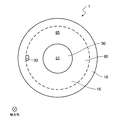
- the electromagnet 100 has a magnetic core 1 and a coil 2.
- the coil 2 is formed in a cylindrical shape by winding a conducting wire a plurality of times.
- the magnetic core 1 has a core member 50 and a yoke member 60.
- the core member 50 includes a core portion 11 that is a cylindrical solid body disposed inside the coil 2 and an axial direction of the core portion 11 (hereinafter, the axial direction of the core portion 11 is simply referred to as “axial direction”).
- a columnar facing portion 13 connected to one end and facing the core portion 11 in the axial direction, and an outer edge of the facing portion 13 (that is, the radial direction of the core portion 11 in the facing portion 13 (hereinafter, the radial direction of the core portion 11 is And a cylindrical non-facing portion 14 that is connected to the end portion of the radial direction) and does not face the core portion 11 in the axial direction.
- the non-facing portion 14 is provided with a through hole 30 through which the conducting wire of the coil 2 is inserted along the axial direction. The conducting wire of the coil 2 is drawn to the outside of the magnetic core 1 through the through hole 30.
- the yoke member 60 includes a cylindrical yoke portion 12 disposed on the outer side of the coil 2 and an extending portion 15 connected to one end of the yoke portion 12 in the axial direction and extending from the one end in the axial direction.
- the core part 11 and the yoke part 12 overlap with the arrangement area of the coil 2 in the axial direction.
- the facing portion 13, the non-facing portion 14 and the extending portion 15 do not overlap with the arrangement region of the coil 2 in the axial direction.
- the corner portion 20 formed by the core portion 11 and the non-opposing portion 14 is rounded around the entire axis of the core portion 11.
- the yoke member 60 is provided with an annular recess 61 that fits with the outer edge of the non-opposing portion 14 of the core member 50.
- At least the core member 50 is made of a high magnetic flux density material having a magnetic flux density higher than that of a general magnetic material.
- the yoke member 60 is made of a general magnetic material.
- the general magnetic material is a material having a saturation magnetic flux density of 2.0 T (Tesla) or less, such as a general structural rolled steel (SS400 or the like) or silicon steel.
- the high magnetic flux density material is a material having a saturation magnetic flux density exceeding 2.0 T (Tesla), such as an electromagnetic steel material containing Fe—Co alloy, pure iron, iron nitride, and bismuth.
- materials containing aluminum oxide, especially Fe-49Co-2V and Fe 65 Co 35 have a high saturation magnetic flux density and are suitable as high magnetic flux density materials.
- the magnetic core 1 is obtained by fabricating the core member 50 and the yoke member 60 and then assembling the core member 50 and the yoke member 60 together by press fitting or welding (specifically, the non-opposing portion 14 of the core member 50).
- press fitting or welding specifically, the non-opposing portion 14 of the core member 50.
- the core member 50 and the yoke member 60 are integrated.
- a welded portion 90 is formed on the surface of the portion constituting the facing portion 13 and the non-facing portion 14 of the core member 50 and on the surface 51 opposite to the core portion 11 in the axial direction (the surface where the through hole 30 is opened). Is not provided.
- the magnetic core 1 opposes the end surface (that is, the other end surface in the axial direction of the core portion 11 and the other end surface in the axial direction of the yoke portion 12) facing the counterpart material 200 to which a magnetic attractive force is applied, and the magnetic core 1 in the counterpart material 200. It is preferable that the processing is performed so that the axial distance from the surface is uniform. For example, if the surface of the mating member 200 is flat, the end surface of the magnetic core 1 is also flat. If the surface of the mating material 200 is a curved shape or an uneven shape, the end surface of the magnetic core 1 is also curved along the surface of the mating material 200. The shape is uneven.
- the electromagnet 100 including such a magnetic core 1 can obtain a high magnetic attractive force particularly in a low frequency region (DC to several hundred Hz).
- a low frequency region DC to several hundred Hz.
- Japanese Patent Application Laid-Open No. 2014-2014 which is a prior application of the present inventor. It can be used as a magnetic force generator in a dynamic characteristic measuring apparatus for a centrifugal rotating machine described in Japanese Patent No. 102117.
- the electromagnet 100 as the magnetic force generator of the dynamic characteristic measuring device, it is possible to measure the dynamic characteristic of the rotor with high accuracy.
- the entire core portion 11 is made of a high magnetic flux density material. As will be shown later in the examples, the core 11 has a high magnetic flux density locally in the low frequency region, and is likely to be magnetically saturated. According to the present embodiment, by configuring the entire core portion 11 with a high magnetic flux density material, the magnetic attractive force in the low frequency region can be improved without increasing the size.
- the yoke portion 12 is made of a general magnetic material.
- the core portion 11 has a locally high magnetic flux density in the low frequency region and is likely to be magnetically saturated, whereas the yoke portion 12 has a high magnetic flux density in the low frequency region. It is hard to saturate.
- the usage-amount of a high magnetic flux density material can be reduced and cost reduction is possible.
- the yield of the high magnetic flux density material can be improved.
- the high magnetic flux density material may be an Fe—Co alloy.
- an Fe—Co alloy having a high saturation magnetic flux density among soft magnetic materials as a high magnetic flux density material, a higher magnetic flux density can be obtained in a low frequency region, and the magnetic attractive force can be further improved. be able to.
- the corner portion 20 formed by the core portion 11 and the non-opposing portion 14 has a round shape.
- the magnetic flux concentrates on the corner portion 20, and the magnetic flux density locally increases at the corner portion 20 and is likely to be magnetically saturated.
- angular part 20 can be suppressed and the magnetic attraction force in a low frequency area
- the effect of the shape of the corner 20 is not dependent on the material constituting the corner 20 (that is, when the corner 20 is made of a high magnetic flux density material and when the corner 20 is made of a general magnetic material). In any case configured).
- the facing portion 13 is made of a high magnetic flux density material. As will be shown later in the embodiment, the facing portion 13 is likely to be magnetically saturated because the magnetic flux density locally increases in the low frequency region. According to the above configuration, by configuring not only the core portion 11 but also the facing portion 13 with a high magnetic flux density material, a higher magnetic flux density can be obtained in the low frequency region, and the magnetic attractive force can be further improved. .
- the non-facing portion 14 at least an inner portion connected to the facing portion 13 (in the present embodiment, the entire non-facing portion 14) is made of a high magnetic flux density material.
- the inner portion of the non-facing portion 14 is likely to be magnetically saturated because the magnetic flux density locally increases in the low frequency region. According to the above configuration, a higher magnetic flux density can be obtained in the low frequency region by configuring not only the core portion 11 but also the facing portion 13 and the non-facing portion 14 with at least the inner portion with a high magnetic flux density material. The magnetic attractive force can be further improved.
- the welded portion 90 is not provided on the surface 51 where the through hole 30 into which the conducting wire of the coil 2 is inserted is opened. In this case, it is possible to prevent the molten metal from flowing into the through hole 30 during welding, and to prevent the problem that the molten metal coats the conductive wire or the conductive wire main body or the through hole 30 is blocked.
- the yoke member 60 has a recess 61 that fits into the core member 50.
- variations in the assembly position between the yoke member 60 and the core member 50 and axial and radial displacement due to thermal deformation can be prevented.
- the arrangement space of the coil 2 can be surely secured and assembly failure can be prevented.
- the core portion 11 is inclined with respect to the axial direction, the radial interval between the core portion 11 and the yoke portion 12 becomes non-uniform in the axial direction, and the magnetic attractive force is reduced. According to this, the problem can be suppressed.
- the magnetic flux can be easily passed and the magnetic attractive force can be further improved.
- the core unit 11 is a solid body. In this case, compared with the case where the core part 11 is not solid (that is, has a cavity), a higher magnetic flux density can be obtained and the magnetic attractive force can be further improved.
- the corner portion 20 has a chamfered shape instead of a round shape
- the yoke member 60 includes only the yoke portion 12 and does not include the extension portion 15, and the yoke member 60 has a recess.
- 61 is not provided, and the welded portion 90 is not a corner formed between the outer peripheral surface of the non-opposing portion 14 and one end surface in the axial direction of the extending portion 15, but the outer peripheral surface of the non-opposing portion 14 and the yoke
- the configuration is the same as that of the magnetic core 1 according to the first embodiment except that the portion 12 is provided at a corner portion formed between one end surface in the axial direction of the portion 12.
- the corner portion 20 formed by the core portion 11 and the non-opposing portion 14 has a chamfered shape.
- the magnetic flux concentrates on the corner portion 20, and the magnetic flux density locally increases at the corner portion 20 and is likely to be magnetically saturated.
- angular part 20 can be suppressed and the magnetic attraction force in a low frequency area
- the effect of the shape of the corner 20 is not dependent on the material constituting the corner 20 (that is, when the corner 20 is made of a high magnetic flux density material and when the corner 20 is made of a general magnetic material). In any case configured).
- the corner portion 20 has a right-angle shape, and the outer diameter of the portion constituting the facing portion 13 and the non-facing portion 14 in the core member 50 is the same as the outer diameter of the yoke member 60. (That is, the outer peripheral surface of the non-opposing portion 14 and the outer peripheral surface of the yoke portion 12 overlap in the radial direction), and the welded portion 90 has an outer peripheral surface of the non-opposing portion 14 and one end surface in the axial direction of the yoke portion 12.
- the magnetic core 1 has the same configuration as that of the magnetic core 1 according to the second embodiment, except that it is provided not at the corner portion formed between the outer peripheral surface of the non-opposing portion 14 and the outer peripheral surface of the yoke portion 12. .
- the same effect can be obtained by the same configuration as that of the second embodiment.
- the outer diameter of the portion constituting the facing portion 13 and the non-facing portion 14 in the core member 50 is larger than the outer diameter of the yoke member 60 (that is, the outer peripheral surface of the non-facing portion 14 is
- the welded portion 90 is not the boundary between the outer peripheral surface of the non-opposing portion 14 and the outer peripheral surface of the yoke portion 12, but the axial direction of the non-opposing portion 14.
- the configuration is the same as that of the magnetic core 1 according to the third embodiment except that the corner is formed between the end surface and the outer peripheral surface of the yoke portion 12.
- the same effect can be obtained with the same configuration as that of the third embodiment.
- the core member 50 is a columnar member composed of the core portion 11 and the opposed portion 13 and does not include the non-opposed portion 14, and the yoke member 60 extends not only the yoke portion 12 but also the yoke portion 60.
- the configuration is the same as that of the magnetic core 1 according to the third embodiment except that the protruding portion 15 and the non-opposing portion 14 are included.
- the welded portion 90 and the through hole 30 are not shown in FIG. 6, for example, the core member 50 and the yoke member 60 may be integrally assembled by a method other than welding (such as press fitting). The through hole 30 may not be provided.
- a columnar core member 50 composed of a core portion 11 and a facing portion 13 is made of a high magnetic flux density material and has a bottomed cylindrical shape including a yoke portion 12 and a non-facing portion 14 (a core member at the bottom portion).
- the yoke member 60 (with a hole into which 50 opposing portions 13 are fitted) is made of a general magnetic material.
- the following effects can be obtained in addition to the same effects by the same configuration as that of the third embodiment.
- the magnetic core 1 includes a core member 50 that is a columnar member including a core portion 11 and a facing portion 13.
- the magnetic core 1 can be easily manufactured by configuring the core member 50 having a simple shape (columnar shape) with a high magnetic flux density material.
- the usage-amount of a high magnetic flux density material can be reduced and cost reduction is possible.
- the core member 50 is not a columnar member composed of the core part 11 and the facing part 13, but a part of the core part 11, the facing part 13, and the non-facing part 14 (in the non-facing part 14
- the yoke member 60 does not include the yoke part 12 and the entire non-opposing part 14, but a part of the yoke part 12 and the non-opposing part 14 (non-opposing part).
- 14 has the same configuration as the magnetic core 1 according to the fifth embodiment except that the outer portion 14b includes an outer portion 14b disposed outside the coil 2 with respect to the inner portion 14a.
- the non-opposing portion 14 is divided into an inner portion 14a included in the core member 50 and an outer portion 14b included in the yoke member 60, and the inner portion 14a is made of a high magnetic flux density material,
- the portion 14b is made of a general magnetic material.
- the following effects can be obtained in addition to the same effects by the same configuration as that of the fifth embodiment.
- the non-opposing part 14 has the inner part 14a connected to the opposing part 13, and the outer part 14b arrange
- the outer portion 14b is made of a general magnetic material. In this case, compared with the case where both the inner part 14a and the outer part 14b are made of a high magnetic flux density material in the non-facing portion 14, the amount of the high magnetic flux density material used can be reduced, and the cost can be reduced.
- the core member 50 is not a columnar member composed of the core portion 11 and the facing portion 13 but includes the core portion 11, the facing portion 13, and the non-facing portion 14.
- the configuration is the same as that of the magnetic core 1 according to the fifth embodiment except that the yoke portion 12 and the non-opposing portion 14 are not included, but the yoke portion 12 and the extending portion 15 are included.
- the same effect can be obtained with the same configuration as that of the fifth embodiment.
- the extending portion 15 further extends in the axial direction, and an annular locking portion 16 protruding radially inward from the distal end of the extending portion 15 is provided, the yoke member 60, the outer edge of the non-opposing portion 14 of the core member 50 is fitted in the recess portion 62 (a recess portion formed by the cylindrical portion formed of the yoke portion 12 and the extension portion 15 and the locking portion 16) 62, a through hole 30 has the same configuration as the magnetic core 1 according to the seventh embodiment except that 30 is provided along the axial direction on the locking portion 16 of the yoke member 60 and the non-facing portion 14 of the core member 50.
- a welded portion 90 is annularly provided at a corner formed between the surface 51 of the core member 50 and the inner peripheral side end surface of the locking portion 16 of the yoke member 60.
- the welded portion 90 is not provided on the surface 65 of the yoke member 60 (the surface opposite to the yoke portion 12 in the axial direction (the surface where the through hole 30 is opened)) 65.
- the following effects can be obtained in addition to the same effects by the same configuration as that of the seventh embodiment.
- the welded portion 90 is not provided on the surface 65 where the through hole 30 into which the conducting wire of the coil 2 is inserted is opened. In this case, it is possible to prevent the molten metal from flowing into the through hole 30 during welding, and to prevent the problem that the molten metal coats the conductive wire or the conductive wire main body or the through hole 30 is blocked.
- the yoke member 60 has a recess 62 that fits into the core member 50.
- variations in the assembly position between the yoke member 60 and the core member 50 and axial and radial displacement due to thermal deformation can be prevented.
- the arrangement space of the coil 2 can be surely secured and assembly failure can be prevented.
- the core portion 11 is inclined with respect to the axial direction, the radial interval between the core portion 11 and the yoke portion 12 becomes non-uniform in the axial direction, and the magnetic attractive force is reduced. According to this, the problem can be suppressed.
- the magnetic flux can be easily passed and the magnetic attractive force can be further improved.
- the yoke member 60 has the locking portion 16 that locks the core member 50.
- the locking portion 16 is disposed on the outer side (upper side in FIG. 9) of at least a part of the core member 50 (non-opposing portion 14) in the axial direction.
- the locking portion 16 In the environment where the outer side in the axial direction (the space in which the magnetic core 1 is disposed) with respect to the counterpart material 200 is at a low pressure and the opposite side (the space in which the counterpart material 200 is arranged) such as atmospheric pressure, the locking portion 16 When the yoke member 60 and the core member 50 are merely fixed to each other by welding, the force that the core member 50 tries to move outward in the axial direction (upper side in FIG.
- the magnetic core 1 according to the ninth embodiment has the same configuration as the magnetic core 1 according to the eighth embodiment except that the through hole 30 is provided in the yoke portion 12 along the radial direction.
- the welded portion 90 is not provided on the surface of the yoke portion 12 of the yoke member 60 (the surface on which the through hole 30 is opened) 66.
- the length of the non-opposing portion 14 in the radial direction is short, the outer edge of the non-opposing portion 14 is not fitted in the recess 62 of the yoke member 60, and the through hole 30 is non-opposing.
- the configuration is the same as that of the magnetic core 1 according to the eighth embodiment except that the portion 14 is not provided in the portion 14 and is provided in the locking portion 16 along the axial direction.
- the extending portion 15 of the yoke member 60 protrudes radially inward, and a concave portion (an annular concave portion formed by the extending portion 15 and the locking portion 16) of the yoke member 60. ) 63, the outer edge of the non-opposing portion 14 having a short radial length is fitted, the through-hole 30 is not provided in the non-opposing portion 14, and the diameter of the extending portion 15 is larger than that of the yoke portion 12.
- the configuration is the same as that of the magnetic core 1 according to the eighth embodiment except that the portion protruding inward in the direction is provided along the axial direction.
- the following effect can be obtained in addition to the same effect by the same configuration as that of the eighth embodiment.
- the through hole 30 into which the conducting wire of the coil 2 is inserted is provided in the yoke member 60 and is not provided in the core member 50.
- the conducting wire can be passed without being affected by the positioning accuracy of the core member 50.
- the inner portion 14a and the outer portion 14b are in contact with each other on the inclined surfaces 14x and 16x inclined with respect to the axial direction, not the surface along the axial direction, and the through hole 30 is formed. Except for being provided along the axial direction on the outer portion 14b of the yoke member 60, the configuration is the same as that of the magnetic core 1 according to the sixth embodiment.
- the radially inner tip of the outer portion 14 b corresponds to the locking portion 16 that locks the core member 50.
- the locking portion 16 is disposed on the outer side (upper side in FIG.
- the locking portion 16 has an inclined surface 16x that comes into contact with the inclined surface 14x provided at the radially outer end of the inner portion 14a.
- Each of the inclined surfaces 14x and 16x is inclined so as to go radially inward as going outward in the axial direction (upper side in FIG. 14).
- the inclined surface 16x also corresponds to a fitting portion that is fitted to the core member 50.
- the welded portion 90 is annularly provided between the surface 51 of the core member 50 and the surface 65 of the yoke member 60 (that is, between the inner portion 14a and the outer portion 14b). .
- the through hole 30 through which the conducting wire of the coil 2 is inserted is provided in the yoke member 60 and is not provided in the core member 50.
- the conducting wire can be passed without being affected by the positioning accuracy of the core member 50.
- the yoke member 60 has a fitting portion (the inclined surface 16x) to be fitted with the core member 50.
- variations in the assembly position between the yoke member 60 and the core member 50 and axial and radial displacement due to thermal deformation can be prevented.
- the core portion 11 is restrained from being displaced from the predetermined position in the radial direction or tilted with respect to the axial direction, the arrangement space of the coil 2 can be surely secured and assembly failure can be prevented. .
- the core portion 11 when the core portion 11 is inclined with respect to the axial direction, the radial interval between the core portion 11 and the yoke portion 12 becomes non-uniform in the axial direction, and the magnetic attractive force is reduced. According to this, the problem can be suppressed. Furthermore, by eliminating the gap between the yoke member 60 and the core member 50, the magnetic flux can be easily passed and the magnetic attractive force can be further improved.
- the yoke member 60 has the locking portion 16 that locks the core member 50.
- the locking portion 16 is disposed on the outer side (upper side in FIG. 14) in the axial direction of at least a part of the core member 50 (the radially outer tip of the inner portion 14a).
- the locking portion 16 When the yoke member 60 and the core member 50 are merely fixed to each other by welding, the force that the core member 50 attempts to move outward in the axial direction (upper side in FIG.
- At least a part of the core member 50 (a radially outer tip of the inner portion 14a) has an inclined surface 14x inclined with respect to the axial direction, and the locking portion 16 comes into contact with the inclined surface 14x.
- the inclined surface 16x is inclined with respect to the axial direction. In this case, by realizing the locking by contacting the inclined surfaces 14x and 16x, the locking portion 16 can be prevented from protruding from the core member 50 in the axial direction, and the size of the magnetic core 1 in the axial direction is large. Can be avoided.
- the magnetic core 1 according to the thirteenth embodiment has the same configuration as the magnetic core 1 according to the twelfth embodiment except that the through hole 30 is provided in the yoke portion 12 along the radial direction.
- the welded portion 90 is not provided on the surface of the yoke portion 12 of the yoke member 60 (the surface on which the through hole 30 is opened) 66.
- the following effects can be obtained in addition to the same effects by the same configuration as the twelfth embodiment.
- the through hole 30 into which the conducting wire of the coil 2 is inserted is provided in the yoke member 60 and is not provided in the core member 50.
- the conducting wire can be passed without being affected by the positioning accuracy of the core member 50.
- FIGS. 16 and 17 show the magnetic flux density when the same current (low frequency region (DC to several hundred Hz)) is applied to the coil in the electromagnet using the magnetic cores according to the comparative example and the embodiment of the present invention. The analysis result of distribution is shown.
- each part (core part 11, yoke part 12, facing part 13, non-facing part 14, etc.) ) are all made of a general magnetic material.
- each part (core part 11, yoke part 12, facing part 13, non-facing part 14, etc.) in the magnetic core 1 having the same shape as the fifth to seventh embodiments (see FIGS. 6 to 8). ) are all made of a high magnetic flux density material.
- the core portion 11 is entirely made of a high magnetic flux density material, so that a high magnetic flux density can be obtained in the low frequency region, and the magnetic attractive force can be improved.
- the cross-sectional area of the magnetic core 1 on the inside and outside of the coil 2 (that is, the cross-sectional area of the core portion 11 and the cross-sectional area of the yoke portion 12 in the plane orthogonal to the axial direction) is obtained.
- the cross-sectional area of the magnetic core 1 is the same between the inner side and the outer side of the coil 2, the magnetic flux density should be uniform, but the analysis shows that the magnetic flux density locally increases in the core portion 11. It was.
- FIG. 18 shows the magnetic attractive force in the low frequency region of the magnetic attractive force of the magnetic core according to the example of the present invention and the magnetic cores according to comparative examples 1 and 2.
- each part core portion 11, yoke portion 12, core portion 11, yoke portion 12, magnetic core 1 having the same shape as in the fifth to seventh embodiments (see FIGS. 6 to 8).
- the facing portion 13 and the non-facing portion 14 are all made of a general magnetic material.
- FIG. 18 is similar to the example of FIG. 17 in the magnetic core 1 having the same shape as the fifth to seventh embodiments (see FIGS. 6 to 8).
- the portion 13 and the non-opposing portion 14 are all made of a high magnetic flux density material.
- FIG. 18 shows that the magnetic attractive force is higher in the low frequency region in the comparative example 2 and the comparative example 2 than in the comparative example 1.
- Comparative Example 2 the magnetic attractive force in the low frequency region is slightly improved as compared with Comparative Example 1, but since the high magnetic flux density material is limited to a part of the core portion 11, the magnetic attractive force in the low frequency region is improved. It can be seen that the effect is limited.
- -A core part is not limited to a column shape, A prismatic shape etc. may be sufficient. Further, the core portion may not be solid (that is, may have a cavity).
- the yoke portion is not limited to a cylindrical shape, and may be a rectangular tube shape or the like. -Each part (a core part, a yoke part, an opposing part, a non-opposing part, etc.) of a magnetic core may be comprised with the same member, and may be comprised with a different member.
- the material of the parts other than the core part is not particularly limited, and the magnetic core as in the above embodiment May be made of a high magnetic flux density material.
- -A fitting part is not limited to a recessed part, A convex part may be sufficient.
- -A fitting part is not limited to fitting with a non-opposing part, You may fit with any part in a core member.
- locking part is not limited to latching a non-opposing part, You may latch any part in a core member.
- the magnetic core which concerns on this invention is not limited to being used for the magnetic force generator in the dynamic characteristic measuring apparatus of a centrifugal rotary machine, You may be used for arbitrary electromagnets.
Abstract
磁心(1)は、コイル(2)の内側に配置される柱状のコア部(11)と、コイル(2)の外側に配置される筒状のヨーク部(12)とを有する。コア部(11)及びヨーク部(12)は、軸方向においてコイル(2)の配置領域と重なる。コア部(11)の全体が、一般磁性材料よりも磁束密度が高い高磁束密度材料で構成されている。
Description
本発明は、電磁石に用いられる磁心に関する。
ソレノイドコア等の電磁石に用いられる磁心において、特許文献1、2のような技術が知られている。特許文献1には、大部分が圧縮成形体(表面に絶縁被膜を有する磁性粉末(軟質磁性粉末)からなる)で構成され、先端部分が磁性バルク体(Fe-Co系合金からなる)で構成された磁心が示されている。特許文献2には、大部分が磁性複合材料(絶縁性材料で被覆された鉄系磁性粉末を加圧成形した圧粉材料等)で構成され、磁性複合材料部に挟設された高磁束密度材料部が設けられた磁心が示されている。特許文献1には、磁心を上記のような構成にすることで、高速応答性が良好でかつコア先端面への高精度な面加工が可能となることが示されている。特許文献2には、磁心を上記のような構成にすることで、磁束密度が高い状態を維持しつつ過電流が発生し難くなることが示されている。
本願発明者は、磁心についての研究開発を進める中で、特許文献1、2のような構成では、高周波領域(10kHz以上)において高い磁束密度(即ち、高い磁気吸引力)が得られるものの、低周波領域(DC~数百Hz)において高い磁束密度(即ち、高い磁気吸引力)を得ることができないことを発見した。
なお、磁心のサイズを大きくすることで磁気吸引力を向上させることはできるが、配置スペースの問題等から、サイズを大きくすることなく磁気吸引力を向上させることが望まれる。
本発明の目的は、サイズを大きくすることなく低周波領域における磁気吸引力を向上させることができる磁心を提供することである。
本発明に係る磁心は、筒状のコイルの内側に配置され、軸方向において前記コイルの配置領域と重なる柱状のコア部と、前記コイルの外側に配置され、前記軸方向において前記コイルの配置領域と重なる筒状のヨーク部とを備え、少なくとも前記コア部の全体が、一般磁性材料よりも磁束密度が高い高磁束密度材料で構成されていることを特徴とする。
後に実施例で示すように、コア部は、低周波領域において、磁束密度が局所的に高くなり、磁気飽和し易い。本発明によれば、コア部の全体を高磁束密度材料で構成することにより、サイズを大きくすることなく低周波領域における磁気吸引力を向上させることができる。
前記ヨーク部は、前記一般磁性材料で構成されてよい。後に実施例で示すように、コア部は、低周波領域において、磁束密度が局所的に高くなり、磁気飽和し易いのに対し、ヨーク部は、低周波領域において、磁束密度が高くならず、磁気飽和し難い。上記構成によれば、ヨーク部をも高磁束密度材料で構成する場合に比べ、高磁束密度材料の使用量を減らすことができ、低コスト化が可能である。また、歩留まりが良いコア部に高磁束密度材料を使用し、歩留まりが悪いヨーク部に一般磁性材料を使用することで、高磁束密度材料の歩留まりを改善することができる。
前記高磁束密度材料は、Fe-Co系合金であってよい。この場合、高磁束密度材料として、軟磁性体の中でも飽和磁束密度の高いFe-Co系合金を用いることで、低周波領域において、より高い磁束密度が得られ、磁気吸引力をより一層向上させることができる。
本発明に係る磁心は、前記コア部に接続し、前記軸方向において前記コイルの配置領域と重ならず、前記軸方向において前記コア部と対向する対向部と、前記対向部に接続し、前記軸方向において前記コイルの配置領域と重ならず、前記軸方向において前記コア部と対向しない非対向部とをさらに備え、前記コア部と前記非対向部とがなす角部がアール形状又は面取り形状であってよい。後に実施例で示すように、コア部と非対向部とがなす角部が直角形状であると、角部に磁束が集中し、角部において磁束密度が局所的に高くなって磁気飽和し易い。上記構成によれば、コア部と非対向部とがなす角部がアール形状又は面取り形状であることにより、角部への磁束の集中を抑制し、低周波領域における磁気吸引力をより一層向上させることができる。
本発明に係る磁心は、前記コア部に接続し、前記軸方向において前記コイルの配置領域と重ならず、前記軸方向において前記コア部と対向する対向部をさらに備え、前記対向部が前記高磁束密度材料で構成されてよい。後に実施例で示すように、対向部は、低周波領域において、磁束密度が局所的に高くなり、磁気飽和し易い。上記構成によれば、コア部のみならず対向部を高磁束密度材料で構成することにより、低周波領域において、より高い磁束密度が得られ、磁気吸引力をより一層向上させることができる。
本発明に係る磁心は、前記コア部と前記対向部とからなる柱状のコア部材を有してよい。この場合、シンプルな形状のコア部材を高磁束密度材料で構成することで、磁心の製造が容易になる。また、非対向部をも高磁束密度材料で構成する場合に比べ、高磁束密度材料の使用量を減らすことができ、低コスト化が可能である。
本発明に係る磁心は、前記対向部に接続し、前記軸方向において前記コイルの配置領域と重ならず、前記軸方向において前記コア部と対向しない非対向部をさらに備え、前記非対向部において少なくとも前記対向部に接続する内側部分が前記高磁束密度材料で構成されてよい。後に実施例で示すように、非対向部の内側部分は、低周波領域において、磁束密度が局所的に高くなり、磁気飽和し易い。上記構成によれば、コア部のみならず、対向部と、非対向部において少なくとも内側部分とを高磁束密度材料で構成することにより、低周波領域において、より高い磁束密度が得られ、磁気吸引力をより一層向上させることができる。
前記非対向部は、前記対向部に接続する内側部分と、前記内側部分よりも前記コイルの外側に配置される外側部分とを有し、前記内側部分が前記高磁束密度材料で構成されており、前記外側部分が前記一般磁性材料で構成されてよい。この場合、非対向部において内側部分及び外側部分の両方を高磁束密度材料で構成する場合に比べ、高磁束密度材料の使用量を減らすことができ、低コスト化が可能である。
前記コイルの導線が貫挿される貫通孔が開口した表面に、溶接部が設けられていなくてよい。この場合、溶接時に貫通孔に溶湯が流れ込むことが回避され、溶湯により導線の被覆や導線本体が破損する問題や貫通孔が塞がる問題を防止することができる。
前記コイルの導線が貫挿される貫通孔が、前記ヨーク部を構成するヨーク部材に設けられており、前記コア部を構成するコア部材に設けられていなくてよい。この場合、コア部材の位置決め精度の影響を受けずに導線を通すことができる。
前記ヨーク部を構成するヨーク部材が、前記コア部を構成するコア部材と嵌合する嵌合部を有してよい。この場合、ヨーク部材とコア部材との組立位置のばらつきや熱変形による軸方向及び径方向のずれを防止することができる。ひいては、コア部が所定の位置から径方向にずれたり軸方向に対して傾いたりすることが抑制されることから、コイルの配置スペースを確実に確保でき、組立不良を防止することができる。また、コア部が軸方向に対して傾くと、コア部とヨーク部との間の径方向の間隔が軸方向において不均一になり、磁気吸引力が低下してしまうが、上記構成によれば当該問題を抑制することができる。さらには、ヨーク部材とコア部材との間の隙間をなくすことで、磁束を通過し易くし、磁気吸引力をより一層向上させることができる。
前記ヨーク部を構成するヨーク部材が、前記コア部を構成するコア部材を係止する係止部であって、前記コア部材の少なくとも一部の前記軸方向の外側に配置された係止部を有してよい。例えば軸方向の外側が低圧・反対側が高圧の環境下において、係止部が設けられておらず、ヨーク部材とコア部材とが互いに溶接により固定されているだけの場合、コア部材が軸方向の外側に移動しようとする力が溶接部にかかり、溶接部が破断して、コア部材が軸方向の外側に抜け出す問題が生じ得る。これに対し、上記構成によれば、上記力を係止部で受けることにより、コア部材が軸方向の外側に抜け出す問題を効果的に防止することができる。
前記コア部材の少なくとも一部が、前記軸方向に対して傾斜した第1傾斜面を有し、前記係止部が、前記第1傾斜面と接触するように前記軸方向に対して傾斜した第2傾斜面を有してよい。この場合、傾斜面同士の接触により係止を実現することで、軸方向において係止部がコア部材から突出しないようにすることができ、軸方向における磁心のサイズの大型化を回避することができる。
前記コア部は、中実体であってよい。この場合、コア部が中実体でない(即ち、空洞を有する)場合に比べ、より高い磁束密度が得られ、磁気吸引力をより一層向上させることができる。
本発明によれば、コア部の全体を高磁束密度材料で構成することにより、サイズを大きくすることなく低周波領域における磁気吸引力を向上させることができる。
先ず、図1及び図2を参照し、本発明の第1実施形態に係る磁心1を用いた電磁石100について説明する。
電磁石100は、磁心1及びコイル2を有する。
コイル2は、導線を複数回巻回することにより、円筒状に形成されている。
磁心1は、コア部材50及びヨーク部材60を有する。
コア部材50は、コイル2の内側に配置される円柱状の中実体であるコア部11と、コア部11における軸方向(以下、コア部11の軸方向を単に「軸方向」という。)の一端に接続しかつ軸方向においてコア部11と対向する円柱状の対向部13と、対向部13の外縁(即ち、対向部13におけるコア部11の径方向(以下、コア部11の径方向を単に「径方向」という。)の端部)に接続しかつ軸方向においてコア部11と対向しない円筒状の非対向部14とを含む。非対向部14には、コイル2の導線が貫挿される貫通孔30が軸方向に沿って設けられている。コイル2の導線は、貫通孔30を介して磁心1の外側に引き出されている。
ヨーク部材60は、コイル2の外側に配置される円筒状のヨーク部12と、ヨーク部12における軸方向の一端に接続しかつ当該一端から軸方向に延出した延出部15とを含む。
コア部11及びヨーク部12は、軸方向においてコイル2の配置領域と重なる。対向部13、非対向部14及び延出部15は、軸方向においてコイル2の配置領域と重ならない。
コア部11と非対向部14とがなす角部20は、コア部11の軸周り全体において、アール形状となっている。また、ヨーク部材60には、コア部材50の非対向部14の外縁と嵌合する環状の凹部61が設けられている。
少なくともコア部材50は、一般磁性材料よりも磁束密度が高い高磁束密度材料で構成されている。ヨーク部材60は、一般磁性材料で構成されている。ここで、一般磁性材料とは、飽和磁束密度が2.0T(テスラ)以下の材料であり、例えば一般構造用圧延鋼材(SS400等)や珪素鋼である。高磁束密度材料とは、飽和磁束密度が2.0T(テスラ)を超える材料であり、例えば、Fe-Co系合金、純鉄、窒化鉄、ビスマスを含有した電磁鋼材等である。Fe-Co系合金の中でも、特に酸化アルミニウムを含有した材料、Fe-49Co-2V、Fe65Co35は、飽和磁束密度が高く、高磁束密度材料として適している。
磁心1は、コア部材50及びヨーク部材60のそれぞれを作製した後、コア部材50及びヨーク部材60を圧入や溶接により一体に組み立てたもの(具体的には、コア部材50の非対向部14の外縁をヨーク部材60の凹部61に嵌合させ、非対向部14の外周面と延出部15における軸方向の一端面との間に形成される隅部に環状に溶接部90を設けることで、コア部材50及びヨーク部材60を一体にしたもの)である。コア部材50における対向部13及び非対向部14を構成する部分の表面であって、軸方向においてコア部11とは反対側の表面(貫通孔30が開口した表面)51には、溶接部90が設けられていない。
磁心1は、磁気吸引力を作用させる相手材200に対向する端面(即ち、コア部11の軸方向の他端面及びヨーク部12の軸方向の他端面)と相手材200における磁心1に対向する表面との軸方向の間隔が均一になるように加工されていることが好ましい。例えば、相手材200の表面が平坦であれば磁心1の端面も平坦とし、相手材200の表面が湾曲形状又は凹凸形状であれば磁心1の端面も相手材200の表面に沿った湾曲形状又は凹凸形状とする。
このような磁心1を含む電磁石100は、特に低周波領域(DC~数百Hz)において高い磁気吸引力が得られるものであり、例えば、本願発明者の先願である日本国特開2014-102117号公報に記載の遠心式回転機械の動特性測定装置における磁力発生器として用いることができる。当該動特性測定装置の磁気磁力発生器として電磁石100を用いることで、ロータの動特性を高精度に測定することが可能となる。
以上に述べたように、本実施形態によれば、コア部11の全体が、高磁束密度材料で構成されている。後に実施例で示すように、コア部11は、低周波領域において、磁束密度が局所的に高くなり、磁気飽和し易い。本実施形態によれば、コア部11の全体を高磁束密度材料で構成することにより、サイズを大きくすることなく低周波領域における磁気吸引力を向上させることができる。
ヨーク部12は、一般磁性材料で構成されている。後に実施例で示すように、コア部11は、低周波領域において、磁束密度が局所的に高くなり、磁気飽和し易いのに対し、ヨーク部12は、低周波領域において、磁束密度が高くならず、磁気飽和し難い。上記構成によれば、ヨーク部12をも高磁束密度材料で構成する場合に比べ、高磁束密度材料の使用量を減らすことができ、低コスト化が可能である。また、歩留まりが良いコア部11に高磁束密度材料を使用し、歩留まりが悪いヨーク部12に一般磁性材料を使用することで、高磁束密度材料の歩留まりを改善することができる。
高磁束密度材料は、Fe-Co系合金であってよい。この場合、高磁束密度材料として、軟磁性体の中でも飽和磁束密度の高いFe-Co系合金を用いることで、低周波領域において、より高い磁束密度が得られ、磁気吸引力をより一層向上させることができる。
コア部11と非対向部14とがなす角部20が、アール形状である。後に実施例で示すように、角部20が直角形状であると、角部20に磁束が集中し、角部20において磁束密度が局所的に高くなって磁気飽和し易い。上記構成によれば、角部20がアール形状であることにより、角部20への磁束の集中を抑制し、低周波領域における磁気吸引力をより一層向上させることができる。なお、このような角部20の形状による効果は、角部20を構成する材料によらず(即ち、角部20が高磁束密度材料で構成されている場合及び角部20が一般磁性材料で構成されている場合のいずれにおいても)得ることができる。
対向部13が、高磁束密度材料で構成されている。後に実施例で示すように、対向部13は、低周波領域において、磁束密度が局所的に高くなり、磁気飽和し易い。上記構成によれば、コア部11のみならず対向部13を高磁束密度材料で構成することにより、低周波領域において、より高い磁束密度が得られ、磁気吸引力をより一層向上させることができる。
非対向部14において少なくとも対向部13に接続する内側部分(本実施形態では、非対向部14の全体)が高磁束密度材料で構成されている。後に実施例で示すように、非対向部14の内側部分は、低周波領域において、磁束密度が局所的に高くなり、磁気飽和し易い。上記構成によれば、コア部11のみならず、対向部13と、非対向部14において少なくとも内側部分とを高磁束密度材料で構成することにより、低周波領域において、より高い磁束密度が得られ、磁気吸引力をより一層向上させることができる。
コイル2の導線が貫挿される貫通孔30が開口した表面51に、溶接部90が設けられていない。この場合、溶接時に貫通孔30に溶湯が流れ込むことが回避され、溶湯により導線の被覆や導線本体が破損する問題や貫通孔30が塞がる問題を防止することができる。
ヨーク部材60が、コア部材50と嵌合する凹部61を有する。この場合、ヨーク部材60とコア部材50との組立位置のばらつきや熱変形による軸方向及び径方向のずれを防止することができる。ひいては、コア部11が所定の位置から径方向にずれたり軸方向に対して傾いたりすることが抑制されることから、コイル2の配置スペースを確実に確保でき、組立不良を防止することができる。また、コア部11が軸方向に対して傾くと、コア部11とヨーク部12との間の径方向の間隔が軸方向において不均一になり、磁気吸引力が低下してしまうが、上記構成によれば当該問題を抑制することができる。さらには、ヨーク部材60とコア部材50との間の隙間をなくすことで、磁束を通過し易くし、磁気吸引力をより一層向上させることができる。
コア部11は、中実体である。この場合、コア部11が中実体でない(即ち、空洞を有する)場合に比べ、より高い磁束密度が得られ、磁気吸引力をより一層向上させることができる。
次に、図3を参照し、本発明の第2実施形態について説明する。
第2実施形態に係る磁心1は、角部20がアール形状ではなく面取り形状となっている点、ヨーク部材60がヨーク部12のみを含み延出部15を含まない点、ヨーク部材60に凹部61が設けられていない点、溶接部90が非対向部14の外周面と延出部15における軸方向の一端面との間に形成される隅部ではなく非対向部14の外周面とヨーク部12における軸方向の一端面との間に形成される隅部に設けられている点を除き、第1実施形態に係る磁心1と同じ構成である。
第2実施形態によれば、第1実施形態と同様の構成による同様の効果に加え、以下のような効果を得ることができる。
第2実施形態では、コア部11と非対向部14とがなす角部20が、面取り形状である。後に実施例で示すように、角部20が直角形状であると、角部20に磁束が集中し、角部20において磁束密度が局所的に高くなって磁気飽和し易い。上記構成によれば、角部20が面取り形状であることにより、角部20への磁束の集中を抑制し、低周波領域における磁気吸引力をより一層向上させることができる。なお、このような角部20の形状による効果は、角部20を構成する材料によらず(即ち、角部20が高磁束密度材料で構成されている場合及び角部20が一般磁性材料で構成されている場合のいずれにおいても)得ることができる。
次に、図4を参照し、本発明の第3実施形態について説明する。
第3実施形態に係る磁心1は、角部20が直角形状である点、コア部材50における対向部13及び非対向部14を構成する部分の外径がヨーク部材60の外径と同じである(即ち、非対向部14の外周面とヨーク部12の外周面とが径方向において重なっている)点、溶接部90が非対向部14の外周面とヨーク部12における軸方向の一端面との間に形成される隅部ではなく非対向部14の外周面とヨーク部12の外周面との境界部に設けられている点を除き、第2実施形態に係る磁心1と同じ構成である。
第3実施形態によれば、第2実施形態と同様の構成による同様の効果を得ることができる。
次に、図5を参照し、本発明の第4実施形態について説明する。
第4実施形態に係る磁心1は、コア部材50における対向部13及び非対向部14を構成する部分の外径がヨーク部材60の外径よりも大きい(即ち、非対向部14の外周面がヨーク部12の外周面よりも径方向において外側にある)点、溶接部90が非対向部14の外周面とヨーク部12の外周面との境界部ではなく非対向部14における軸方向の他端面とヨーク部12の外周面との間に形成される隅部に設けられている点を除き、第3実施形態に係る磁心1と同じ構成である。
第4実施形態によれば、第3実施形態と同様の構成による同様の効果を得ることができる。
次に、図6を参照し、本発明の第5実施形態について説明する。
第5実施形態に係る磁心1は、コア部材50がコア部11と対向部13とからなる柱状の部材であって非対向部14を含まない点、ヨーク部材60がヨーク部12のみではなく延出部15及び非対向部14を含む点を除き、第3実施形態に係る磁心1と同じ構成である。なお、図6には、溶接部90及び貫通孔30が示されていないが、例えば、溶接以外の方法(圧入等)でコア部材50及びヨーク部材60が一体に組み立てられてもよく、また、貫通孔30を設けなくてもよい。第5実施形態では、コア部11と対向部13とからなる柱状のコア部材50を高磁束密度材料で構成し、ヨーク部12及び非対向部14を含む有底円筒状の(底部にコア部材50の対向部13が嵌合される孔が形成された)ヨーク部材60を一般磁性材料で構成している。
第5実施形態によれば、第3実施形態と同様の構成による同様の効果に加え、以下のような効果を得ることができる。
第5実施形態に係る磁心1は、コア部11と対向部13とからなる柱状の部材であるコア部材50を有する。この場合、シンプルな形状(柱状)のコア部材50を高磁束密度材料で構成することで、磁心1の製造が容易になる。また、非対向部14をも高磁束密度材料で構成する場合に比べ、高磁束密度材料の使用量を減らすことができ、低コスト化が可能である。
次に、図7を参照し、本発明の第6実施形態について説明する。
第6実施形態に係る磁心1は、コア部材50がコア部11と対向部13とからなる柱状の部材ではなくコア部11と対向部13と非対向部14の一部(非対向部14において対向部13に接続する内側部分14a)とを含む点、ヨーク部材60がヨーク部12と非対向部14の全体とを含むのではなくヨーク部12と非対向部14の一部(非対向部14において内側部分14aよりもコイル2の外側に配置される外側部分14b)とを含む点を除き、第5実施形態に係る磁心1と同じ構成である。第6実施形態では、非対向部14がコア部材50に含まれる内側部分14aとヨーク部材60に含まれる外側部分14bとに分割されており、内側部分14aを高磁束密度材料で構成し、外側部分14bを一般磁性材料で構成している。
第6実施形態によれば、第5実施形態と同様の構成による同様の効果に加え、以下のような効果を得ることができる。
第6実施形態では、非対向部14が、対向部13に接続する内側部分14aと、内側部分14aよりもコイル2の外側に配置される外側部分14bとを有し、内側部分14aが高磁束密度材料で構成されており、外側部分14bが一般磁性材料で構成されている。この場合、非対向部14において内側部分14a及び外側部分14bの両方を高磁束密度材料で構成する場合に比べ、高磁束密度材料の使用量を減らすことができ、低コスト化が可能である。
次に、図8を参照し、本発明の第7実施形態について説明する。
第7実施形態に係る磁心1は、コア部材50がコア部11と対向部13とからなる柱状の部材ではなくコア部11と対向部13と非対向部14とを含む点、ヨーク部材60がヨーク部12と非対向部14とを含むのではなくヨーク部12と延出部15とを含む点を除き、第5実施形態に係る磁心1と同じ構成である。
第7実施形態によれば、第5実施形態と同様の構成による同様の効果を得ることができる。
次に、図9及び図10を参照し、本発明の第8実施形態について説明する。
第8実施形態に係る磁心1は、延出部15がさらに軸方向に延出し、延出部15の先端から径方向内側に突出した環状の係止部16が設けられている点、ヨーク部材60の凹部(ヨーク部12及び延出部15からなる円筒部と係止部16とで形成される凹部)62にコア部材50の非対向部14の外縁が嵌合している点、貫通孔30がヨーク部材60の係止部16とコア部材50の非対向部14とに軸方向に沿って設けられている点を除き、第7実施形態に係る磁心1と同じ構成である。第8実施形態では、コア部材50の表面51とヨーク部材60の係止部16の内周側端面との間に形成される隅部に、環状に溶接部90が設けられている。ヨーク部材60の表面(軸方向においてヨーク部12とは反対側の表面(貫通孔30が開口した表面))65には、溶接部90が設けられていない。
第8実施形態によれば、第7実施形態と同様の構成による同様の効果に加え、以下のような効果を得ることができる。
第8実施形態では、コイル2の導線が貫挿される貫通孔30が開口した表面65に、溶接部90が設けられていない。この場合、溶接時に貫通孔30に溶湯が流れ込むことが回避され、溶湯により導線の被覆や導線本体が破損する問題や貫通孔30が塞がる問題を防止することができる。
また、第8実施形態では、ヨーク部材60が、コア部材50と嵌合する凹部62を有する。この場合、ヨーク部材60とコア部材50との組立位置のばらつきや熱変形による軸方向及び径方向のずれを防止することができる。ひいては、コア部11が所定の位置から径方向にずれたり軸方向に対して傾いたりすることが抑制されることから、コイル2の配置スペースを確実に確保でき、組立不良を防止することができる。また、コア部11が軸方向に対して傾くと、コア部11とヨーク部12との間の径方向の間隔が軸方向において不均一になり、磁気吸引力が低下してしまうが、上記構成によれば当該問題を抑制することができる。さらには、ヨーク部材60とコア部材50との間の隙間をなくすことで、磁束を通過し易くし、磁気吸引力をより一層向上させることができる。
また、第8実施形態では、ヨーク部材60が、コア部材50を係止する係止部16を有する。係止部16は、コア部材50の少なくとも一部(非対向部14)の軸方向の外側(図9において上側)に配置されている。例えば相手材200に対して軸方向の外側(磁心1が配置された空間)が大気圧等の低圧・反対側(相手材200が配置された空間)が高圧の環境下において、係止部16が設けられておらず、ヨーク部材60とコア部材50とが互いに溶接により固定されているだけの場合、コア部材50が軸方向の外側(図9において上側)に移動しようとする力が溶接部90にかかり、溶接部90が破断して、コア部材50が軸方向の外側に抜け出す問題が生じ得る。これに対し、上記構成によれば、上記力を係止部16で受けることにより、コア部材50が軸方向の外側に抜け出す問題を効果的に防止することができる。
次に、図11を参照し、本発明の第9実施形態について説明する。
第9実施形態に係る磁心1は、貫通孔30がヨーク部12に径方向に沿って設けられている点を除き、第8実施形態に係る磁心1と同じ構成である。ヨーク部材60におけるヨーク部12の表面(貫通孔30が開口した表面)66には、溶接部90が設けられていない。
次に、図12を参照し、本発明の第10実施形態について説明する。
第10実施形態に係る磁心1は、非対向部14の径方向の長さが短く、ヨーク部材60の凹部62に非対向部14の外縁が嵌合していない点、貫通孔30が非対向部14に設けられておらず係止部16に軸方向に沿って設けられている点を除き、第8実施形態に係る磁心1と同じ構成である。
次に、図13を参照し、本発明の第11実施形態について説明する。
第11実施形態に係る磁心1は、ヨーク部材60の延出部15が径方向内側に突出しており、ヨーク部材60の凹部(延出部15と係止部16とで形成される環状の凹部)63に、径方向の長さが短い非対向部14の外縁が嵌合している点、貫通孔30が非対向部14に設けられておらず延出部15におけるヨーク部12よりも径方向内側に突出した部分に軸方向に沿って設けられている点を除き、第8実施形態に係る磁心1と同じ構成である。
第9~第11実施形態によれば、第8実施形態と同様の構成による同様の効果に加え、以下のような効果を得ることができる。
第9~第11実施形態では、コイル2の導線が貫挿される貫通孔30が、ヨーク部材60に設けられており、コア部材50に設けられていない。この場合、コア部材50の位置決め精度の影響を受けずに導線を通すことができる。
次に、図14を参照し、本発明の第12実施形態について説明する。
第12実施形態に係る磁心1は、内側部分14aと外側部分14bとが軸方向に沿った面ではなく軸方向に対して傾斜した傾斜面14x,16xにおいて接触している点、貫通孔30がヨーク部材60の外側部分14bに軸方向に沿って設けられている点を除き、第6実施形態に係る磁心1と同じ構成である。第12実施形態では、外側部分14bにおける径方向内側の先端が、コア部材50を係止する係止部16に該当する。係止部16は、コア部材50の少なくとも一部(内側部分14aにおける径方向外側の先端)の軸方向の外側(図14において上側)に配置されている。係止部16は、内側部分14aにおける径方向外側の先端に設けられた傾斜面14xと接触する傾斜面16xを有する。各傾斜面14x,16xは、軸方向の外側(図14において上側)に向かうにつれて径方向内側に向かうように傾斜している。傾斜面16xは、コア部材50と嵌合する嵌合部にも該当する。また、第12実施形態では、コア部材50の表面51とヨーク部材60の表面65との間(即ち、内側部分14aと外側部分14bとの間)に、環状に溶接部90が設けられている。
第12実施形態によれば、第6実施形態と同様の構成による同様の効果に加え、以下のような効果を得ることができる。
第12実施形態では、コイル2の導線が貫挿される貫通孔30が、ヨーク部材60に設けられており、コア部材50に設けられていない。この場合、コア部材50の位置決め精度の影響を受けずに導線を通すことができる。
また、第12実施形態では、ヨーク部材60が、コア部材50と嵌合する嵌合部(傾斜面16x)を有する。この場合、ヨーク部材60とコア部材50との組立位置のばらつきや熱変形による軸方向及び径方向のずれを防止することができる。ひいては、コア部11が所定の位置から径方向にずれたり軸方向に対して傾いたりすることが抑制されることから、コイル2の配置スペースを確実に確保でき、組立不良を防止することができる。また、コア部11が軸方向に対して傾くと、コア部11とヨーク部12との間の径方向の間隔が軸方向において不均一になり、磁気吸引力が低下してしまうが、上記構成によれば当該問題を抑制することができる。さらには、ヨーク部材60とコア部材50との間の隙間をなくすことで、磁束を通過し易くし、磁気吸引力をより一層向上させることができる。
また、第12実施形態では、ヨーク部材60が、コア部材50を係止する係止部16を有する。係止部16は、コア部材50の少なくとも一部(内側部分14aにおける径方向外側の先端)の軸方向の外側(図14において上側)に配置されている。例えば相手材200に対して軸方向の外側(磁心1が配置された空間)が大気圧等の低圧・反対側(相手材200が配置された空間)が高圧の環境下において、係止部16が設けられておらず、ヨーク部材60とコア部材50とが互いに溶接により固定されているだけの場合、コア部材50が軸方向の外側(図14において上側)に移動しようとする力が溶接部90にかかり、溶接部90が破断して、コア部材50が軸方向の外側に抜け出す問題が生じ得る。これに対し、上記構成によれば、上記力を係止部16で受けることにより、コア部材50が軸方向の外側に抜け出す問題を効果的に防止することができる。
また、コア部材50の少なくとも一部(内側部分14aにおける径方向外側の先端)が、軸方向に対して傾斜した傾斜面14xを有し、係止部16が、傾斜面14xと接触するように軸方向に対して傾斜した傾斜面16xを有する。この場合、傾斜面14x,16x同士の接触により係止を実現することで、軸方向において係止部16がコア部材50から突出しないようにすることができ、軸方向における磁心1のサイズの大型化を回避することができる。
次に、図15を参照し、本発明の第13実施形態について説明する。
第13実施形態に係る磁心1は、貫通孔30がヨーク部12に径方向に沿って設けられている点を除き、第12実施形態に係る磁心1と同じ構成である。ヨーク部材60におけるヨーク部12の表面(貫通孔30が開口した表面)66には、溶接部90が設けられていない。
第13実施形態によれば、第12実施形態と同様の構成による同様の効果に加え、以下のような効果を得ることができる。
第13実施形態では、コイル2の導線が貫挿される貫通孔30が、ヨーク部材60に設けられており、コア部材50に設けられていない。この場合、コア部材50の位置決め精度の影響を受けずに導線を通すことができる。
続いて、本発明を実施例により具体的に説明する。
図16及び図17は、本発明の比較例及び実施例に係る磁心を用いた電磁石において、コイルに同一の電流(低周波領域(DC~数百Hz)の電流)を印加した場合の磁束密度分布の解析結果を示す。
図16の比較例は、第5~第7実施形態(図6~図8参照)と同様の形状の磁心1において、各部(コア部11、ヨーク部12、対向部13、非対向部14等)を全て一般磁性材料で構成したものである。
図17の実施例は、第5~第7実施形態(図6~図8参照)と同様の形状の磁心1において、各部(コア部11、ヨーク部12、対向部13、非対向部14等)を全て高磁束密度材料で構成したものである。
図16の比較例では、コア部11において、一定の磁束密度よりも上昇しない領域が存在することが分かる。即ち、コア部11は、一般磁性材料で構成されている場合、低周波領域において、磁束密度が局所的に高くなり、磁気飽和し易く、高い磁束密度(即ち、高い磁気吸引力)が得られない。
図17の実施例では、コア部11において、図16の比較例に比べ、高い磁束密度が得られることが分かる。即ち、コア部11は、全体を高磁束密度材料で構成することにより、低周波領域において、高い磁束密度が得られ、磁気吸引力を向上させることができる。
なお、図16及び図17の例では、コイル2の内側と外側とでの磁心1の断面積(即ち、軸方向と直交する面におけるコア部11の断面積及びヨーク部12の断面積)を等しくしている。コイル2の内側と外側とでの磁心1の断面積が同一であれば、磁束密度が一様になるはずであるが、解析により、コア部11において局所的に磁束密度が高くなることが分かった。
図18は、本発明の実施例に係る磁心及び比較例1,2に係る磁心の磁気吸引力の低周波領域における磁気吸引力を示す。
図18の比較例1は、図16の比較例と同様、第5~第7実施形態(図6~図8参照)と同様の形状の磁心1において、各部(コア部11、ヨーク部12、対向部13、非対向部14等)を全て一般磁性材料で構成したものである。
図18の比較例2は、第5~第7実施形態(図6~図8参照)と同様の形状の磁心1において、コア部11及びヨーク部12のそれぞれにおける相手材200と対向する端部近傍(即ち、コア部11の軸方向の他端近傍及びヨーク部12の軸方向の他端近傍)を高磁束密度材料で構成し、それ以外の部分を一般磁性材料で構成したものである。
図18の実施例は、図17の実施例と同様、第5~第7実施形態(図6~図8参照)と同様の形状の磁心1において、各部(コア部11、ヨーク部12、対向部13、非対向部14等)を全て高磁束密度材料で構成したものである。
図18から、比較例1よりも比較例2、比較例2よりも実施例の方が、低周波領域において高い磁気吸引力が得られることがわかる。比較例2は、比較例1に比べ、低周波領域における磁気吸引力が若干向上するが、高磁束密度材料がコア部11の一部に限定されるため、低周波領域における磁気吸引力の向上効果は限定的であることが分かる。
以上、本発明の好適な実施の形態について説明したが、本発明は上述の実施形態に限られるものではなく、特許請求の範囲に記載した限りにおいて様々な設計変更が可能なものである。
・コア部は、円柱状に限定されず、角柱状等であってもよい。また、コア部は、中実体でなくてもよい(即ち、空洞を有してもよい)。
・ヨーク部は、円筒状に限定されず、角筒状等であってもよい。
・磁心の各部(コア部、ヨーク部、対向部、非対向部等)は、同じ部材で構成されてもよいし、異なる部材で構成されてもよい。
・コア部の全体が高磁束密度材料で構成されている限り、コア部以外の部分(ヨーク部、対向部、非対向部等)の材料は特に限定されず、上記の実施例のように磁心の全体が高磁束密度材料で構成されてもよい。
・嵌合部は、凹部に限定されず、凸部であってもよい。
・嵌合部は、非対向部と嵌合することに限定されず、コア部材におけるどの部分と嵌合してもよい。
・係止部は、非対向部を係止することに限定されず、コア部材におけるどの部分を係止してもよい。
・本発明に係る磁心は、遠心式回転機械の動特性測定装置における磁力発生器に用いられることに限定されず、任意の電磁石に用いられてよい。
本発明を詳細にまた特定の実施態様を参照して説明したが、本発明の精神と範囲を逸脱することなく様々な変更や修正を加えることができることは当業者にとって明らかである。
本出願は、2016年5月20日出願の日本特許出願(特願2016-101504)、2016年10月11日出願の日本特許出願(特願2016-200368)に基づくものであり、その内容はここに参照として取り込まれる。
本出願は、2016年5月20日出願の日本特許出願(特願2016-101504)、2016年10月11日出願の日本特許出願(特願2016-200368)に基づくものであり、その内容はここに参照として取り込まれる。
本発明によれば、電磁石の磁心のサイズを大きくすることなく磁気吸引力を向上させることできることができる。
1 磁心
2 コイル
11 コア部
12 ヨーク部
13 対向部
14 非対向部
14a 内側部分
14b 外側部分
14x 傾斜面(第1傾斜面)
16 係止部
16x 傾斜面(第2傾斜面、嵌合部)
20 角部
30 貫通孔
50 コア部材
51 表面
60 ヨーク部材
61 凹部(嵌合部)
62 凹部(嵌合部)
63 凹部(嵌合部)
65 表面
66 表面
90 溶接部
100 電磁石
200 相手材
2 コイル
11 コア部
12 ヨーク部
13 対向部
14 非対向部
14a 内側部分
14b 外側部分
14x 傾斜面(第1傾斜面)
16 係止部
16x 傾斜面(第2傾斜面、嵌合部)
20 角部
30 貫通孔
50 コア部材
51 表面
60 ヨーク部材
61 凹部(嵌合部)
62 凹部(嵌合部)
63 凹部(嵌合部)
65 表面
66 表面
90 溶接部
100 電磁石
200 相手材
Claims (15)
- 筒状のコイルの内側に配置され、軸方向において前記コイルの配置領域と重なる柱状のコア部と、
前記コイルの外側に配置され、前記軸方向において前記コイルの配置領域と重なる筒状のヨーク部とを備え、
少なくとも前記コア部の全体が、一般磁性材料よりも磁束密度が高い高磁束密度材料で構成されていることを特徴とする、磁心。 - 前記ヨーク部が前記一般磁性材料で構成されていることを特徴とする、請求項1に記載の磁心。
- 前記高磁束密度材料がFe-Co系合金であることを特徴とする、請求項1又は2に記載の磁心。
- 前記コア部に接続し、前記軸方向において前記コイルの配置領域と重ならず、前記軸方向において前記コア部と対向する対向部と、
前記対向部に接続し、前記軸方向において前記コイルの配置領域と重ならず、前記軸方向において前記コア部と対向しない非対向部とをさらに備え、
前記コア部と前記非対向部とがなす角部がアール形状であることを特徴とする、請求項1に記載の磁心。 - 前記コア部に接続し、前記軸方向において前記コイルの配置領域と重ならず、前記軸方向において前記コア部と対向する対向部と、
前記対向部に接続し、前記軸方向において前記コイルの配置領域と重ならず、前記軸方向において前記コア部と対向しない非対向部とをさらに備え、
前記コア部と前記非対向部とがなす角部が面取り形状であることを特徴とする、請求項1に記載の磁心。 - 前記コア部に接続し、前記軸方向において前記コイルの配置領域と重ならず、前記軸方向において前記コア部と対向する対向部をさらに備え、
前記対向部が前記高磁束密度材料で構成されていることを特徴とする、請求項1に記載の磁心。 - 前記コア部と前記対向部とからなる柱状のコア部材を有することを特徴とする、請求項6に記載の磁心。
- 前記対向部に接続し、前記軸方向において前記コイルの配置領域と重ならず、前記軸方向において前記コア部と対向しない非対向部をさらに備え、
前記非対向部において少なくとも前記対向部に接続する内側部分が前記高磁束密度材料で構成されていることを特徴とする、請求項6に記載の磁心。 - 前記非対向部は、前記対向部に接続する内側部分と、前記内側部分よりも前記コイルの外側に配置される外側部分とを有し、前記内側部分が前記高磁束密度材料で構成されており、前記外側部分が前記一般磁性材料で構成されていることを特徴とする、請求項8に記載の磁心。
- 前記コイルの導線が貫挿される貫通孔が開口した表面に、溶接部が設けられていないことを特徴とする、請求項1に記載の磁心。
- 前記コイルの導線が貫挿される貫通孔が、前記ヨーク部を構成するヨーク部材に設けられており、前記コア部を構成するコア部材に設けられていないことを特徴とする、請求項1に記載の磁心。
- 前記ヨーク部を構成するヨーク部材が、前記コア部を構成するコア部材と嵌合する嵌合部を有することを特徴とする、請求項1に記載の磁心。
- 前記ヨーク部を構成するヨーク部材が、前記コア部を構成するコア部材を係止する係止部であって、前記コア部材の少なくとも一部の前記軸方向の外側に配置された係止部を有することを特徴とする、請求項1に記載の磁心。
- 前記コア部材の少なくとも一部が、前記軸方向に対して傾斜した第1傾斜面を有し、
前記係止部が、前記第1傾斜面と接触するように前記軸方向に対して傾斜した第2傾斜面を有することを特徴とする、請求項13に記載の磁心。 - 前記コア部が中実体であることを特徴とする、請求項1に記載の磁心。
Priority Applications (3)
| Application Number | Priority Date | Filing Date | Title |
|---|---|---|---|
| US16/302,623 US20190295758A1 (en) | 2016-05-20 | 2017-05-16 | Magnetic core |
| KR1020187033239A KR102136670B1 (ko) | 2016-05-20 | 2017-05-16 | 자심 |
| DE112017002576.1T DE112017002576T5 (de) | 2016-05-20 | 2017-05-16 | Magnetkern |
Applications Claiming Priority (4)
| Application Number | Priority Date | Filing Date | Title |
|---|---|---|---|
| JP2016-101504 | 2016-05-20 | ||
| JP2016101504 | 2016-05-20 | ||
| JP2016200368A JP6964971B2 (ja) | 2016-05-20 | 2016-10-11 | 磁心 |
| JP2016-200368 | 2016-10-11 |
Publications (1)
| Publication Number | Publication Date |
|---|---|
| WO2017199935A1 true WO2017199935A1 (ja) | 2017-11-23 |
Family
ID=60325994
Family Applications (1)
| Application Number | Title | Priority Date | Filing Date |
|---|---|---|---|
| PCT/JP2017/018301 WO2017199935A1 (ja) | 2016-05-20 | 2017-05-16 | 磁心 |
Country Status (1)
| Country | Link |
|---|---|
| WO (1) | WO2017199935A1 (ja) |
Citations (5)
| Publication number | Priority date | Publication date | Assignee | Title |
|---|---|---|---|---|
| JPS49121165A (ja) * | 1973-03-28 | 1974-11-19 | ||
| JP2009033051A (ja) * | 2007-07-30 | 2009-02-12 | Sumitomo Electric Ind Ltd | リアクトル用コア |
| JP2009044941A (ja) * | 2007-08-11 | 2009-02-26 | Sumitomo Electric Ind Ltd | アキシャルモータ用コア、ステータおよびアキシャルモータ |
| JP2013162069A (ja) * | 2012-02-08 | 2013-08-19 | Sumitomo Electric Ind Ltd | リアクトル、コンバータ、及び電力変換装置 |
| JP2015185673A (ja) * | 2014-03-24 | 2015-10-22 | Ntn株式会社 | 磁性素子 |
-
2017
- 2017-05-16 WO PCT/JP2017/018301 patent/WO2017199935A1/ja active Application Filing
Patent Citations (5)
| Publication number | Priority date | Publication date | Assignee | Title |
|---|---|---|---|---|
| JPS49121165A (ja) * | 1973-03-28 | 1974-11-19 | ||
| JP2009033051A (ja) * | 2007-07-30 | 2009-02-12 | Sumitomo Electric Ind Ltd | リアクトル用コア |
| JP2009044941A (ja) * | 2007-08-11 | 2009-02-26 | Sumitomo Electric Ind Ltd | アキシャルモータ用コア、ステータおよびアキシャルモータ |
| JP2013162069A (ja) * | 2012-02-08 | 2013-08-19 | Sumitomo Electric Ind Ltd | リアクトル、コンバータ、及び電力変換装置 |
| JP2015185673A (ja) * | 2014-03-24 | 2015-10-22 | Ntn株式会社 | 磁性素子 |
Similar Documents
| Publication | Publication Date | Title |
|---|---|---|
| CN109215960A (zh) | 电抗器 | |
| US20080231138A1 (en) | Laminated core | |
| JP2010130819A (ja) | 界磁子及び界磁子の製造方法 | |
| KR20180118178A (ko) | 회전 액추에이터 및 로봇 | |
| JP2008312304A (ja) | ステータコア及びそれを用いたモータ | |
| JP2014003125A (ja) | リアクトル | |
| JP4841673B2 (ja) | 電磁石アクチュエータ | |
| JP6964971B2 (ja) | 磁心 | |
| JP6464125B2 (ja) | 第一端板および第二端板を備えたリアクトル | |
| WO2017199935A1 (ja) | 磁心 | |
| JP5644002B2 (ja) | ソレノイド | |
| JP2014090069A (ja) | リアクトル | |
| JP4062723B2 (ja) | 回転形モータおよびその製造方法 | |
| JP6193081B2 (ja) | ロータリトランス付きモータ | |
| JP2014225516A (ja) | リアクトル | |
| JP2006345672A (ja) | 回転電機の固定子 | |
| US20070205672A1 (en) | Linear Motor And Manufacturing Method Of Linear Motor | |
| JP2005057955A (ja) | モータ及びその回転子の製造方法 | |
| JP6175633B2 (ja) | 回転型差動変圧器 | |
| JP2011135091A (ja) | 磁芯およびコイル部品 | |
| JP2020048411A (ja) | 電動機 | |
| JP4093364B2 (ja) | 回転電機用封止永久磁石体並びにそれを用いた永久磁石回転電機及び回転子 | |
| JP2013045937A (ja) | ボビン及びチョークコイル | |
| US20210367460A1 (en) | Motor | |
| JP2008022592A (ja) | 電動モータ |
Legal Events
| Date | Code | Title | Description |
|---|---|---|---|
| ENP | Entry into the national phase |
Ref document number: 20187033239 Country of ref document: KR Kind code of ref document: A |
|
| 121 | Ep: the epo has been informed by wipo that ep was designated in this application |
Ref document number: 17799359 Country of ref document: EP Kind code of ref document: A1 |
|
| 122 | Ep: pct application non-entry in european phase |
Ref document number: 17799359 Country of ref document: EP Kind code of ref document: A1 |