WO2017199803A1 - 電磁弁 - Google Patents
電磁弁 Download PDFInfo
- Publication number
- WO2017199803A1 WO2017199803A1 PCT/JP2017/017637 JP2017017637W WO2017199803A1 WO 2017199803 A1 WO2017199803 A1 WO 2017199803A1 JP 2017017637 W JP2017017637 W JP 2017017637W WO 2017199803 A1 WO2017199803 A1 WO 2017199803A1
- Authority
- WO
- WIPO (PCT)
- Prior art keywords
- valve
- pair
- iron core
- valve body
- valve seat
- Prior art date
Links
Images


Classifications
-
- F—MECHANICAL ENGINEERING; LIGHTING; HEATING; WEAPONS; BLASTING
- F16—ENGINEERING ELEMENTS AND UNITS; GENERAL MEASURES FOR PRODUCING AND MAINTAINING EFFECTIVE FUNCTIONING OF MACHINES OR INSTALLATIONS; THERMAL INSULATION IN GENERAL
- F16K—VALVES; TAPS; COCKS; ACTUATING-FLOATS; DEVICES FOR VENTING OR AERATING
- F16K31/00—Actuating devices; Operating means; Releasing devices
- F16K31/02—Actuating devices; Operating means; Releasing devices electric; magnetic
- F16K31/06—Actuating devices; Operating means; Releasing devices electric; magnetic using a magnet, e.g. diaphragm valves, cutting off by means of a liquid
- F16K31/0644—One-way valve
- F16K31/0655—Lift valves
-
- B—PERFORMING OPERATIONS; TRANSPORTING
- B60—VEHICLES IN GENERAL
- B60T—VEHICLE BRAKE CONTROL SYSTEMS OR PARTS THEREOF; BRAKE CONTROL SYSTEMS OR PARTS THEREOF, IN GENERAL; ARRANGEMENT OF BRAKING ELEMENTS ON VEHICLES IN GENERAL; PORTABLE DEVICES FOR PREVENTING UNWANTED MOVEMENT OF VEHICLES; VEHICLE MODIFICATIONS TO FACILITATE COOLING OF BRAKES
- B60T8/00—Arrangements for adjusting wheel-braking force to meet varying vehicular or ground-surface conditions, e.g. limiting or varying distribution of braking force
- B60T8/32—Arrangements for adjusting wheel-braking force to meet varying vehicular or ground-surface conditions, e.g. limiting or varying distribution of braking force responsive to a speed condition, e.g. acceleration or deceleration
- B60T8/34—Arrangements for adjusting wheel-braking force to meet varying vehicular or ground-surface conditions, e.g. limiting or varying distribution of braking force responsive to a speed condition, e.g. acceleration or deceleration having a fluid pressure regulator responsive to a speed condition
- B60T8/36—Arrangements for adjusting wheel-braking force to meet varying vehicular or ground-surface conditions, e.g. limiting or varying distribution of braking force responsive to a speed condition, e.g. acceleration or deceleration having a fluid pressure regulator responsive to a speed condition including a pilot valve responding to an electromagnetic force
- B60T8/3615—Electromagnetic valves specially adapted for anti-lock brake and traction control systems
- B60T8/363—Electromagnetic valves specially adapted for anti-lock brake and traction control systems in hydraulic systems
-
- F—MECHANICAL ENGINEERING; LIGHTING; HEATING; WEAPONS; BLASTING
- F16—ENGINEERING ELEMENTS AND UNITS; GENERAL MEASURES FOR PRODUCING AND MAINTAINING EFFECTIVE FUNCTIONING OF MACHINES OR INSTALLATIONS; THERMAL INSULATION IN GENERAL
- F16K—VALVES; TAPS; COCKS; ACTUATING-FLOATS; DEVICES FOR VENTING OR AERATING
- F16K1/00—Lift valves or globe valves, i.e. cut-off apparatus with closure members having at least a component of their opening and closing motion perpendicular to the closing faces
- F16K1/32—Details
- F16K1/34—Cutting-off parts, e.g. valve members, seats
-
- F—MECHANICAL ENGINEERING; LIGHTING; HEATING; WEAPONS; BLASTING
- F16—ENGINEERING ELEMENTS AND UNITS; GENERAL MEASURES FOR PRODUCING AND MAINTAINING EFFECTIVE FUNCTIONING OF MACHINES OR INSTALLATIONS; THERMAL INSULATION IN GENERAL
- F16K—VALVES; TAPS; COCKS; ACTUATING-FLOATS; DEVICES FOR VENTING OR AERATING
- F16K27/00—Construction of housing; Use of materials therefor
- F16K27/02—Construction of housing; Use of materials therefor of lift valves
- F16K27/029—Electromagnetically actuated valves
-
- F—MECHANICAL ENGINEERING; LIGHTING; HEATING; WEAPONS; BLASTING
- F16—ENGINEERING ELEMENTS AND UNITS; GENERAL MEASURES FOR PRODUCING AND MAINTAINING EFFECTIVE FUNCTIONING OF MACHINES OR INSTALLATIONS; THERMAL INSULATION IN GENERAL
- F16K—VALVES; TAPS; COCKS; ACTUATING-FLOATS; DEVICES FOR VENTING OR AERATING
- F16K31/00—Actuating devices; Operating means; Releasing devices
- F16K31/02—Actuating devices; Operating means; Releasing devices electric; magnetic
- F16K31/06—Actuating devices; Operating means; Releasing devices electric; magnetic using a magnet, e.g. diaphragm valves, cutting off by means of a liquid
- F16K31/0603—Multiple-way valves
- F16K31/061—Sliding valves
- F16K31/0613—Sliding valves with cylindrical slides
-
- F—MECHANICAL ENGINEERING; LIGHTING; HEATING; WEAPONS; BLASTING
- F16—ENGINEERING ELEMENTS AND UNITS; GENERAL MEASURES FOR PRODUCING AND MAINTAINING EFFECTIVE FUNCTIONING OF MACHINES OR INSTALLATIONS; THERMAL INSULATION IN GENERAL
- F16K—VALVES; TAPS; COCKS; ACTUATING-FLOATS; DEVICES FOR VENTING OR AERATING
- F16K31/00—Actuating devices; Operating means; Releasing devices
- F16K31/02—Actuating devices; Operating means; Releasing devices electric; magnetic
- F16K31/06—Actuating devices; Operating means; Releasing devices electric; magnetic using a magnet, e.g. diaphragm valves, cutting off by means of a liquid
- F16K31/0675—Electromagnet aspects, e.g. electric supply therefor
Definitions
- the present invention relates to an electromagnetic valve that moves a valve body in a displacement direction of the movable iron core by exciting a solenoid and displacing the movable iron core, thereby switching a connection state between a plurality of ports.
- Patent Document 1 An electromagnetic valve configured to move a valve body in a displacement direction of the movable iron core by exciting a solenoid and displacing the movable iron core, thereby switching a connection state between a plurality of ports is disclosed in Patent Document 1.
- the movable iron core is formed in a substantially rectangular cross section, and a valve body including an elastic portion made of a resin material at one end in the axial direction of the movable iron core. Is fixedly attached.
- a valve housing chamber in which the valve body is housed is formed in the valve body, and a plurality of ports are communicated with the valve housing chamber.
- An opening communicating with one of the ports is opened on the bottom surface of the valve housing chamber, and a valve seat to which the elastic portion of the valve body contacts and separates so as to surround the opening. Is formed.
- the technical problem of the present invention is to provide an electromagnetic valve having a structure for operating a valve body by displacing a movable iron core by excitation of a solenoid, and providing it at a lower cost by improving the design to a more rational design structure. Is to be able to.
- the solenoid valve according to the present invention has a first end on one axial end side and a second end on the other axial end side, and is displaced in the axial direction by an excitation action of a solenoid.
- An electromagnetic valve having a valve body that contacts and separates from a valve seat in a room to switch a connection state between the ports, wherein the movable iron core is an iron on the first end side formed in a plate shape having a substantially rectangular cross section.
- a second end side valve support portion connected to the iron core portion, and the valve support portion includes a pair of support arms, and the pair of support arms includes the movable iron It is arranged in parallel with the width direction of the core, and is continuously connected to the iron core portion seamlessly.
- the surfaces on both sides in the thickness direction of the movable iron core are each composed of a single plane continuously extending over the iron core portion and the pair of support arms, and are parallel to each other.
- the valve element is supported between the pair of support arms.
- the valve body is supported between the pair of support arms so as to be axially movable relative to the support arms, and the valve body is disposed on the valve seat side in the valve chamber.
- An elastic member that seats the valve body on the valve seat by urging the valve body toward the valve seat is provided, and the movable iron core is opposite to the urging direction of the valve body by the elastic member in the pair of support arms.
- a valve engaging portion that disengages the valve body from the valve seat against the urging force of the elastic member by engaging the engaged portion of the valve body seated on the valve seat when displaced Is provided.
- the valve engaging portion is It is comprised so that it may become non-contact with respect to this valve body.
- the valve seat is formed on a bottom wall surface facing the second end of the movable iron core in the valve chamber, and a distal end surface of the support arm is a plane orthogonal to the axis.
- an arm contact surface is formed on the bottom wall surface, and the arm contact surface is formed by a plane parallel to the distal end surface of the support arm.
- the valve seat is a first valve seat formed on the bottom wall surface of the valve chamber, and is opposed to the first valve seat along the axis in the valve chamber.
- a second valve seat is provided at a position, and the valve body is disposed between the first valve seat and the second valve seat, and is always urged toward the first valve seat by the elastic member.
- the valve engaging portions provided on the pair of support arms are made of a thin plate having spring properties in the axial direction, and the movable iron core is displaced from the second end side to the first end side.
- the valve engaging portion provided in the pair of support arms is formed by a thin plate having a spring property in the axial direction, so that when the valve body is seated in contact with the second valve seat, The external force acting in the axial direction can be reduced by absorbing the valve engaging portion. Therefore, wear and irreversible deformation (permanent distortion) of the valve body due to such external force repeatedly acting on the valve body can be suppressed as much as possible.
- the pair of support arms have engaging claws protruding in a direction facing away from each other between the tip portions, and between the tip portions of the pair of support arms.
- the cap member has a pair of engagement openings that engage with the engagement claws of the pair of support arms, and the pair of engagement members.
- a valve opening that is disposed between the openings and allows the valve body to be seated on the first valve seat; and the valve engaging portion is formed at a peripheral portion of the valve opening.
- the engaged portion is formed on the end surface facing the first valve seat side.
- the valve body has a pair of guide grooves that open in opposite directions and extend in the axial direction, and the pair of support arms are in the pair of guide grooves. Is supported so as to be slidable in the axial direction between the pair of support arms by being fitted so as to be relatively movable in the axial direction.
- the valve seat is formed on a bottom wall surface facing the second end of the movable iron core of the valve chamber, and the pair of support arms protrudes in directions opposite to each other.
- a cap member formed of a thin metal plate and having a substantially U-shaped cross section is attached between the tip ends of the pair of support arms, and the cap members are engaged with the engaging claws of the pair of support arms.
- the valve engaging portion is formed at a peripheral portion, and the valve engaging portion faces the valve seat side of the valve body when the movable iron core is displaced from the second end side to the first end side.
- the solenoid valve has a solenoid part, and the solenoid part is fitted in the center hole so that the iron core part of the movable iron core is slidable in the axial direction.
- a bobbin having a coil wound around its outer periphery, and a magnetic ring disposed at the end of the bobbin on the valve body side so as to surround the opening of the center hole, and the center hole of the bobbin Has a pair of first inner surfaces and another pair of second inner surfaces, and the pair of first inner surfaces are parallel to each other on both sides in the thickness direction of the iron core portion.
- the pair of second inner surfaces are opposed to a pair of side end surfaces that are parallel to each other at both ends in the width direction of the iron core, and both sides of the pair of first inner surfaces in the width direction are opposed to the pair of surfaces.
- the step is formed with a step portion that narrows the distance between the first inner surfaces than the intermediate portion, A pair of protrusions are formed on the pair of second inner surfaces in the axial direction, and the pair of side end surfaces of the iron core portion are slid in the axial direction by the pair of protrusions.
- a pair of surfaces of the iron core is supported slidably in the axial direction by the stepped portion, and the iron core passes through the magnetic ring and has a tip toward the valve body. And protruding.
- the opening of the center hole is provided with a pair of engagement projection walls extending in the axial direction from the pair of second inner surfaces, and the magnetic ring is provided with the engagement projection.
- An engaged hole portion into which the wall is fitted is provided, and the magnetic ring is positioned at a position coaxial with the bobbin by fitting of the engaging protruding wall into the engaged hole portion.
- the structure and form of the movable iron core is suppressed by integrally forming the iron core portion and the valve support portion of the movable iron core seamlessly. As a result, the manufacturing cost can be suppressed.
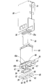
- FIG. 2 is a schematic enlarged cross-sectional view of a main part showing a state around a valve chamber in FIG. 1. It is a sectional side view which shows the state at the time of the excitation in the said solenoid valve. It is a longitudinal cross-sectional view of FIG. FIG. 5 is a schematic enlarged cross-sectional view of a main part showing a state around a valve chamber in FIG. 4. It is a schematic perspective view which decomposes
- FIG. 5 is an enlarged cross-sectional view of a main part along the line VIII-VIII in FIG. 4. It is a schematic perspective view which shows the state before mounting
- FIG. 10 is a schematic perspective view showing a state in which the guide groove of the valve body is fitted between the pair of support arms from the state of FIG. 9.
- FIG. 11 is a schematic perspective view showing a state in which a cap member is installed between a pair of support arms from the state of FIG. 10.
- It is a schematic sectional drawing which shows the state which accommodated the movable iron core in the center hole of a bobbin.
- FIG. 4 is an enlarged cross-sectional view of a main part taken along line XIV-XIV in FIG. It is a schematic perspective view which shows the state which attached the magnetic body ring to the engagement pro
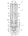
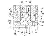
- the electromagnetic valve 1 according to the present invention is roughly divided into a main valve portion 2 having a valve body 3 for switching a flow path through which a pressure fluid such as air flows, and a solenoid for driving the valve body 3 of the main valve portion 2.
- the main valve portion 2 and the solenoid portion 7 are coupled in series in the direction of the axis L of the electromagnetic valve 1.
- the main valve portion 2 has a valve body 10 having a rectangular cross section as can be seen from FIGS. On one side surface of the valve body 10, a supply port P, an output port A, and a discharge port R are provided. In addition, a valve chamber 11 in which the supply port P, the output port A, and the discharge port R communicate with each other is formed in the valve body 10. A gasket 29 is attached to each of these ports.
- the valve chamber 11 is provided with a first valve seat 12 and a second valve seat 13 with which the valve body 3 contacts and separates.
- the first valve seat 12 and the second valve seat 13 are provided.
- the seat 13 is disposed to face the axis L direction.
- the first valve seat 12 is formed on the bottom wall surface 14 of the valve chamber 11 so as to surround the supply through hole 15 formed at a substantially central position of the bottom wall surface 14, and toward the solenoid unit 7 side. Protruding.
- the supply through hole 15 communicates with a supply communication path 16 provided on the bottom side of the valve body 10 with respect to the bottom wall surface 14, and the supply communication path 16 is connected to the supply port P. Thereby, the supply port P communicates with the valve chamber 11 through the supply through hole 15.
- the second valve seat 13 is provided in a retainer 17 attached to the valve chamber 11.
- the retainer 17 is made of a resin material, and is accommodated inside the valve chamber 11 so as to be positioned closer to the opening end side (solenoid part 7 side) of the valve chamber 11 than the valve body 3.
- An annular outer peripheral portion 20 fitted to the inner peripheral wall of the valve chamber 11 and a projecting portion 19 formed so as to project toward the first valve seat 12 inside the annular outer peripheral portion 20 are provided.
- a discharge passage hole 21 communicating with the discharge port R is formed at the tip (top) of the protrusion 19 formed in the retainer 17.
- the second valve seat 13 having an annular shape is formed around the periphery.
- An annular groove 22 is formed in the annular outer peripheral portion 20, and seal members 23 for keeping the air tightness in the valve chamber 11 are mounted at positions on both sides of the annular groove 22 in the axis L direction.
- the annular groove 22 communicates with a discharge communication passage 24 that communicates with the discharge passage hole 21, whereby the discharge port R passes through the annular groove 22, the discharge communication passage 24, and the discharge passage hole 21. It communicates with the inside of the valve chamber 11.
- a pair of insertion holes 25, 25 through which a pair of support arms 45, 45 of the movable iron core 40 described later are inserted are formed between the protruding portion 19 and the annular outer peripheral portion 20 (FIG. 1). And FIG. 9).
- the poppet type valve element 3 is accommodated in the space between the first valve seat 12 and the second valve seat 13 in the valve chamber 11.
- the valve body 3 is formed in a substantially rectangular shape with a resin material having both elasticity and sealing properties such as rubber, and the valve body 3 is in contact with the first valve seat 12 and the second valve seat 13. By separating, the connection state between the ports P, A, and R is switched.
- an elastic member 26 made of a coil spring is interposed between the valve body 3 and the retainer 17 that is fixed to the valve body 2, and the elastic body 2 allows the valve body 3 to be connected.
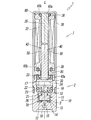
- the valve body 3 When the solenoid 7 is in a non-excited state (demagnetized state), the valve body 3 is always biased toward the first valve seat 12 by the biasing force of the elastic member 26. (See FIGS. 1 to 3).
- the proximal end side of the protrusion 19 in the retainer 17 functions as a spring seat for the elastic member 26.
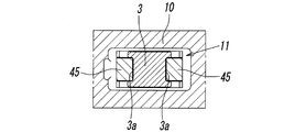
- the valve body 3 has a pair of guide grooves 3a and 3a that open in opposite directions on the end face in the width direction (left and right direction in FIG. 8) of the valve body 3, respectively. It is formed so as to extend in the axis L direction. A pair of support arms 45, 45 of a movable iron core 40, which will be described later, are fitted in these guide grooves 3 a, 3 a, so that the valve body 3 is moved in the axis L direction between the pair of support arms 45, 45. It is slidably supported.
- the guide grooves 3a, 3a it is possible to prevent the valve body 3 from moving in a direction orthogonal to the axis of the movable iron core 40. Therefore, it is possible to prevent the shaft of the valve body 3 from shaking.
- the valve body 3 can be reliably seated against the first valve seat 12 and the second valve seat 13.
- the solenoid portion 7 includes a magnetic cover 30 having a rectangular cross section whose one end side in the axis L direction (upper side in FIG. 1) is closed by a bonnet 31.
- a bobbin 60 having an excitation coil 32 wound around the outer periphery, a fixed iron core 35 mounted in a center hole 60a of the bobbin 60, and the center hole 60a.
- a movable iron core 40 that is slidably fitted in the direction of the axis L therein, and a magnetic ring disposed at the end of the bobbin 60 on the valve body 2 side so as to surround the opening of the center hole 60a. 80.
- annular grooves 60b are formed between the bonnet 31 and the bobbin 60, and between the bobbin 60 and the magnetic ring 80, respectively. Seal members 38 are respectively attached. Further, a pair of coil terminals 39 and 39 electrically connected to the exciting coil 32 protrude from the side surface of the magnetic cover 30, and lead wires are connected to the coil terminals 39 and 39, respectively.
- the fixed iron core 35 is formed of a metal material in a substantially rectangular plate shape, and a flange portion 35a is provided on one end side in the axis L direction (upper end side in FIG. 1).
- the fixed iron core 35 is sandwiched between the bobbin 60 and the bonnet 31 in a state where the flange portion 35a is engaged with the end of the bobbin 60 on the bonnet 31 side.
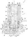
- the movable iron core 40 is displaced in the direction of the axis L by the excitation and demagnetizing action of the solenoid unit 7, and the displacement in the direction of the axis L causes the valve body 3 to be moved to the first valve seat 12 and the second valve seat. 13 to be seated. That is, when the exciting coil 32 is in the energized state (excited state), as shown in FIGS. 4 to 6, the movable iron core 40 is attracted to the fixed iron core 35, and the valve body 3 is moved to the first valve seat. 12 is opened and seated on the second valve seat 13, and the supply port P and the output port A communicate with each other through the valve chamber 11.
- the exciting coil 32 when the exciting coil 32 is in a non-energized state (demagnetized state), the movable iron core 40 is separated from the fixed iron core 35 as shown in FIGS.
- the body 3 opens the second valve seat 13 and sits on the first valve seat 12, and the output port A and the discharge port R communicate with each other through the valve chamber 11.
- the movable iron core 40 has a first end on one end side in the axis L direction and a second end on the other end side, and the first end side has a plate-like iron core having a substantially rectangular cross section.
- a portion 43 is formed, and on the second end side, a valve support portion (support arm 45) that protrudes in the direction of the axis L from the end face 43a of the iron core portion 43 is formed.
- the iron core portion 43 is a portion that faces the fixed iron core 35 and is attracted to or separated from the fixed iron core 35 by energization or non-energization of the excitation coil 32.
- the valve support portion is formed by a pair of support arms 45 and 45 that are continuously connected to the iron core portion 43 seamlessly. These support arms 45 are arranged in parallel so as to be symmetrical with respect to the axis L at both ends of the movable iron core 40 in the width direction (left and right direction in FIG. 1).
- the movable iron core 40 is made of a single metal plate having magnetism, and the iron core portion 43 and the valve support portion (that is, the support arm 45) are integrally formed by punching out such a metal plate. ing. As a result, as shown in FIGS.
- each of the pair of surfaces (side surfaces) 50 and 50 that are parallel to each other on both sides in the thickness direction (left-right direction in FIG. 2) of the movable iron core 40 is A single plane extending continuously over the iron core 43 and the support arms 45, 45 is formed.
- the pair of support arms 45, 45 extend into the valve chamber 11 in the valve body 3 through the pair of insertion holes 25, 25 opened in the retainer 17.
- the pair of guide grooves 3 a and 3 a (see FIG. 8) formed in the valve body 3 are fitted so as to be relatively displaceable in the axis L direction with respect to the valve body 3.
- the valve body 3 is supported between the pair of support arms 45 and slidably in the direction of the axis L.
- the valve body 3 is not fixedly provided on the movable iron core 40, but is movably supported by the movable iron core 40, whereby the degree of freedom in designing the valve support portion of the movable iron core 40 is further increased. Therefore, the structure and form of the valve support part can be further simplified.
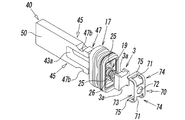
- the pair of support arms 45, 45 have hook-like engagement claws 47, 47 projecting in directions opposite to each other at their tip portions, respectively. Yes.
- an inclined surface 47 a that is gradually inclined toward the axis L toward the distal end surface 46 side of the support arm 45 is formed, and the proximal ends of the engaging claws 47, 47 are formed.
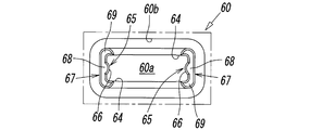
- a cap member 70 formed of a thin metal plate having a spring property and having a substantially U-shaped cross section is installed between the distal ends of the pair of support arms 45 and 45.
- the cap member 70 is provided with a pair of engagement openings 71, 71 that engage with the engagement claws 47, 47, and a valve opening 72 positioned between the pair of engagement openings 71, 71.
- the valve body 3 is seated on the first valve seat 12 through the valve opening 72.
- the cap member 70 includes a thin plate-like valve engagement portion 73 that extends in a direction orthogonal to the axis L and has spring properties in the axis L direction, and left and right sides of the valve engagement portion 73.
- a pair of locking portions 74 and 74 extending in a substantially vertical direction from both ends are provided, and the connecting portion between the valve engaging portion 73 and the locking portion 74 has a smooth arc shape.
- valve body 3 is separated from the first valve seat 12 against the urging force of the elastic member 26 and is seated on the second valve seat 13. Further, the valve engagement portion 73 is provided with the valve opening 72, and the valve body 3 can be seated on the first valve seat 12 through the valve opening 72 as shown in FIG. It is made possible.
- the engagement openings 71, 71 are formed in a rectangular shape, and are provided at positions straddling the valve engagement portion 73 and the locking portion 74.
- a bend portion 75 that bends outward is provided on the distal end side of the locking portion 74.
- the operation of attaching the cap member 70 between the support arms 45 is performed as follows. First, as shown in FIG. 9, the movable iron core 40, the retainer 17, the elastic member 26, the valve body 3, and the cap member 70 are prepared, and then the elastic spring composed of the coil spring is provided on the outer periphery of the protruding portion 19 of the retainer 17. The member 26 is attached. Then, the shafts of the movable iron core 40 and the retainer 17 to which the elastic member 26 is attached are aligned, and the pair of support arms 45, 45 are connected to one side in the axis L direction of the retainer 17 (opposite side of the projecting portion 19). ) Through the insertion holes 25 and 25 of the retainer 17.
- valve body 3 is pushed toward the retainer 17 side against the biasing force of the elastic member 26 from the opposite side (projecting portion 19 side) of the movable iron core 40 (support arm 45), and the insertion hole
- the guide grooves 3a and 3a of the valve body 3 are fitted between a pair of support arms 45 and 45 extending from 25 and 25 (see FIG. 10).
- the cap member 70 is attached between the support arms 45 and 45.
- the cap member 70 is supported in a state where the opening side (the locking portion 74 side) of the cap member 70 is opposed to the front end surfaces 46, 46 of the support arms 45, 45.
- the bent portions 75 of the pair of locking portions 74 and 74 in the cap member 70 are inclined surfaces of the engaging claws 47 provided at the distal end portion of the support arm 45. Since it gets on 47a, the space
- the opening edge (free end side) of the locking opening 71 of the locking portion 74 is displaced to the position of the engaging surface 47b of the engaging claw 47, and the position of the locking opening 71 and the engaging claw
- the expanded locking portions 74 and 74 are elastically restored, so that the engaging claw 47 fits into the locking opening 71 as shown in FIG.
- the attachment of the member 70 is completed.
- the tip surfaces 46, 46 of the pair of support arms 45, 45 are formed on a plane orthogonal to the axis L.
- a pair of arm contact surfaces 27, 27 are formed to contact and separate the tip surfaces 46, 46.
- the pair of arm contact surfaces 27, 27 are planes parallel to the distal end surface 46 of the support arm 45.
- these arm contact surfaces 27, 27 are provided on both sides of the first valve seat 12 provided on the bottom wall surface 14, that is, on both sides in the width direction (left and right direction in FIG. 3) of the valve body 10, respectively. It protrudes toward the part 7 side.
- the height at which the arm contact surface 27 protrudes from the bottom wall surface 14 into the valve chamber 11 is lower than the height at which the first valve seat 12 protrudes from the bottom wall surface 14 to the valve chamber 11. That is, the arm contact surface 27 is located closer to the bottom wall surface 14 than the first valve seat 12.
- the movable iron core 40 is displaced to the second end side (first valve seat 12 side), and the valve body 3 is moved to the first valve seat 12.
- the front end surfaces 46 and 46 of the pair of support arms 45 and 45 come into contact with the arm contact surfaces 27 and 27.
- the valve engaging portion 73 of the cap member 70 is not in contact with the engaged portion 4 of the valve body 3, and the valve engaging portion 73 and the engaged portion 4 are not in contact with each other.
- a gap G smaller than the stroke of the movable iron core 40 is formed between them.
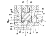
- the center hole 60a of the bobbin 60 that accommodates the movable iron core 40 has a substantially rectangular cross section by a pair of first inner surfaces 61 and 61 and another pair of second inner surfaces 65 and 65, as shown in FIG. Is formed.
- the first inner surfaces 61, 61 are opposed to a pair of surfaces 50, 50 located on both sides in the thickness direction of the movable iron core 40, and the second inner surfaces 65, 65 are formed of the movable iron core 40 (iron core portion).
- 43) are opposed to a pair of side end surfaces 51 and 51 which are located at both ends in the width direction (left and right direction in FIG. 12) and are parallel to each other.
- the both side portions 62, 62 in the width direction of the pair of first inner surfaces 61, 61 are configured so that the distance between the first inner surfaces 61, 61 is narrower than the intermediate portion 63 sandwiched between the both side portions 62, 62.
- the step portion 64 is formed.
- the stepped portion 64 extends in the direction of the axis L and continues from both side portions 62, 62 of the first inner surface 61 to the second inner surface 65 in the circumferential direction of the center hole 60a.
- a pair of protrusions 66 and 66 are formed in the pair of second inner surfaces 65 and 65 in the direction of the axis L, respectively.
- the protrusion 66 is formed in a direction (inward) opposite to each other from the second inner surfaces 65, 65, and the cross-sectional shape thereof is an arc shape.
- the iron core portion 43 of the movable iron core 40 is inserted into the central hole 60a of the bobbin 60, so that the pair of side end surfaces 51, 51 are connected to the axis L by the pair of protrusions 66, 66.
- the pair of surfaces 50 and 50 are supported by the step 64 so as to be slidable in the direction of the axis L.
- the movable iron core 40 penetrates through the magnetic ring 80 and has a tip protruding toward the valve body 2 side.
- both end surfaces 51 and 51 of the movable iron core 40 and both side portions of the pair of surfaces 50 and 50 are slid by the protrusion 66 and the step portion 64 in the center hole 60a of the bobbin 60. Since it is supported so that it can move freely, it can prevent effectively that the axis of movable iron core 40 shakes.
- a pair of the central hole 60a facing the valve body 2 side has a pair extending from the pair of second inner surfaces 65, 65 in the direction of the axis L. Engagement protrusion walls 67, 67 are provided.
- the magnetic ring 80 arranged so as to surround the center hole 60 a is provided with an engaged hole portion 81, and the engaging protruding walls 67 and 67 are fitted into the engaged hole portion 81. By combining, the magnetic ring 80 is positioned so as to be coaxial with the bobbin 60.
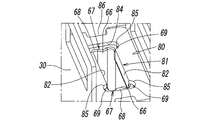
- the engagement protrusion wall 67 of the bobbin 60 includes a side wall portion 68 that faces both side portions 51, 51 of the movable iron core 40, and both sides ( It comprises an arcuate wall 69 having a semicircular shape on both sides in the vertical direction in FIG.
- the engaged hole portion 81 of the magnetic ring 80 has a pair of parallelly extending facing the pair of surfaces 50, 50 of the movable iron core 40. It consists of first surface portions 82 and 82 and second surface portions 83 and 83 provided on both sides of the first surface portions 82 and 82.
- the distance between the first surface portions 82 and 82 is the thickness of the movable iron core 40 (the distance between the pair of surfaces 50 and 50) and between the intermediate portions 63 and 63 of the first inner surface 61 in the center hole 60a. It is formed larger than the distance.
- the second surface portion 83 is a portion with which the engagement protrusion 67 is engaged, and is formed on a straight portion 84 extending in a direction orthogonal to the first surface portion 82 and on both sides of the straight portion 84. It consists of a semicircular arc-shaped portion 85.
- the linear portion 84 is engaged with the outer peripheral surface of the side wall portion 68 of the engaging protrusion wall 67, and the arc-shaped portion 85 is engaged with the outer peripheral surface of the arc-shaped end portion 69 of the engaging protrusion wall 67. It is configured.
- the magnetic ring 80 has a substantially rectangular outer peripheral surface in plan view, and a pair of concave portions 86, 86 are provided on both side surfaces in the width direction on the outer peripheral surface.
- the pair of recesses 86, 86 are engaged with a pair of inward projections 28, 28 formed in the valve chamber 11 of the valve body 2.
- the engaging protrusion 67 of the bobbin 60 and the engaged hole 81 of the magnetic ring 80 are provided.
- the recess 86 and the inward projection 28 are engaged with each other, whereby the axes of the magnetic body ring 80 and the center hole 60a of the bobbin 60 are made to coincide with each other. Furthermore, when the magnetic body ring 80 is attached to the opening of the bobbin 60, the engaging protrusion 67 is located between the side portions 51, 51 of the movable iron core 40 and the second surface portion 83 of the magnetic body ring 80. Intervene in. In this state, since a clearance is formed between the first surface portion 82 of the magnetic body ring 80 and the surface 50 of the movable iron core 40, the movable iron core 40 and the magnetic body ring 80 are in direct contact with each other. Therefore, it is possible to more reliably prevent the efficiency of the solenoid unit 7 from decreasing.
- the pair of support arms 45 and 45 of the movable iron core 40 has a distal end surface 46 of the bottom wall of the valve chamber 11 as shown in FIG.
- the pair 14 is in a state of being in contact with the pair of arm contact surfaces 27, 27.
- the valve body 3 is seated on the first valve seat 12 located in the valve opening 72 of the cap member 70 between the pair of support arms 45, 45.
- the end surface (engaged portion 4) of the valve body 3 facing the first valve seat 12 and the valve engaging portion 73 of the cap member 70 are not in contact with each other.
- a gap G smaller than the stroke amount of the movable iron core 40 is formed between the engaging portion 4 and the valve engaging portion 73.
- the exciting coil 32 is in an excited state.
- the valve body 3 is not displaced to the second valve seat 13 side simultaneously with the displacement of the movable iron core 40, but first, the gap G between the engaged portion 4 and the valve engaging portion 73 is used.
- the gap G becomes zero, the valve engaging portion 73 engages with the engaged portion 4 of the valve body 3, and then the valve body 3 moves toward the second valve seat 13 side. .
- the said valve body 3 seats to the 2nd valve seat 13, the said discharge through-hole 21 is closed, and the 1st valve seat 12 facing the 2nd valve seat 13 is open
- the supply port P communicates with the output port A through the supply through hole 15 and the valve chamber 11, and the pressure fluid supplied from the supply port P is output through the output port A (see FIG. 4—See FIG.
- the valve engaging portion 73 of the cap member 70 provided on the pair of support arms 45, 45 is made of a thin plate having a spring property in the direction of the axis L, so that the valve body 3 is the second valve seat 13.
- the valve body 3 when the front end surface 46 of the support arm 45 abuts on the arm abutment surface 27, the valve body 3 includes the engaged portion 4 that faces the first valve seat 12 and the valve engagement of the cap member 70. It is configured to be seated on the first valve seat 12 with the gap G provided between the joint portion 73. With this configuration, when the valve body 3 is seated on the first valve seat 12, it is possible to prevent the kinetic energy of the movable iron core 40 from directly acting on the valve body 3, The external force that acts in the direction of the axis L on the valve body 3 can be reduced.
- the iron core portion 43 and the valve support portion of the movable iron core 40 are integrally formed seamlessly, thereby suppressing the number of parts and the movable iron core.
- the structure and form of 40 can also be simplified, and as a result, the manufacturing cost can be suppressed.
- the electromagnetic valve according to the present invention has been described, it is needless to say that the present invention is not limited to the above-described embodiment, and various design changes can be made without departing from the scope of the claims.
- a three-port solenoid valve is used, but the number of ports is not limited to this, and may be two ports.
Abstract
Description
この特許文献1に開示された電磁弁においては、上記可動鉄芯が断面略矩形に形成されていて、この可動鉄芯の軸方向の一端に、樹脂製材料から成る弾性部を備えた弁体が固定的に取り付けられてる。また、弁ボディ内には、上記弁体が収容された弁収容室が形成されていて、該弁収容室には複数のポートが連通されている。そして、該弁収容室の底面には、それらポートの中の一つに連通する開口部が開設されており、その開口部の周囲を取り囲むように上記弁体の弾性部が接離する弁座が形成されている。
このように、本発明によれば、可動鉄芯の鉄芯部と弁支持部とを継ぎ目なく一体成形することで、部品点数を抑制して、可動鉄芯の構造や形態も簡素化することができるようになり、その結果、製造コストを抑制することが可能となる。
このように、弁体を可動鉄芯に固定的に設けることなく別体とすることによって、可動鉄芯の弁支持部の設計自由度がさらに増すため、該弁支持部の構造や形態をより簡素化することが可能となる。
そうすることにより、弁体が弁座に当接して着座するときに、可動鉄芯の運動エネルギーが弁体に直接作用するのを防ぐことができるため、弁体に対して軸方向に作用する外力を緩和することができる。よって、そのような外力が弁体に繰り返し作用することによる該弁体の摩耗や不可逆的な変形(永久歪み)を抑制することができ、該弁体の軸方向における寸法の経時的な変化を抑制することが可能となる。その結果、可動鉄芯のストローク量、すなわち弁座からの弁体の離間量の変動が抑制されて、該弁座を通じて流れる流体の流量や電磁弁の応答性の変動を可及的に抑制することが可能となる。
そうすることにより、上記弁体が弁座に当接して着座したときに、可動鉄芯が弁ボディに対して正確に位置決めされるため、電磁弁の応答性をより正確に管理することが可能となる。
このように、一対の支持アームに設けられた弁係合部を軸方向にバネ性を有する薄板によって形成したので、弁体が第2弁座に当接して着座するときに、弁体に対して作用する軸方向の外力を、該弁係合部が吸収することで緩和することができる。そのため、そのような外力が弁体に繰り返し作用することによる該弁体の摩耗や不可逆的な変形(永久歪み)を可及的に抑制することができる。
このようにすることで、可動鉄芯の弁支持部に対する弁体の装着、及び上記弁係合部の形成を、金属薄板から成る簡単な構造のキャップ部材にて実現することが可能となる。
そうすることにより、弁体が可動鉄芯の軸と直交する方向へ移動するのを防止することができるため、弁体の軸のぶれを防止することができ、弁体を確実に弁座に対して着座させることが可能となる。
このようにすることで、可動鉄芯の弁支持部に対する弁体の装着、及び上記弁係合部の形成を、金属薄板から成る簡単な構造のキャップ部材にて実現することが可能となる。
このように、可動鉄芯における両側端面及び一対の表面の両側部が、ボビンの中心穴内において、突条及び段部によって摺動自在に支持されているため、可動鉄芯の軸がぶれるのを効果的に防止することができる。
そうすることで、可動鉄芯が磁性体リングに接触することによるソレノイド部の効率低下をより確実に防止することが可能となる。
これとは逆に、上記励磁コイル32が非通電状態(消磁状態)にあるときは、図1-図3に示すように、上記可動鉄芯40は固定鉄芯35から離間して、上記弁体3が第2弁座13を開放して第1弁座12に着座し、上記出力ポートAと排出ポートRとが弁室11を介して連通する。
このように、上記弁体3を可動鉄芯40に固定的に設けることなく、該可動鉄心40に可動に支持させることにより、該可動鉄芯40の弁支持部の設計の自由度がさらに増すため、該弁支持部の構造や形態をより簡素化することが可能となる。
このように、本実施形態では、可動鉄芯40の両側端面51,51と、一対の表面50,50の両側部とが、ボビン60の中心穴60a内で突条66及び段部64によって摺動自在に支持されているため、可動鉄芯40の軸がぶれるのを効果的に防止することができる。
また、上記第2面部83は、上記係合突部67が係合する部分であって、上記第1面部82と直交する向きに延びる直線部84と、該直線部84の両側に形成された半円弧状の弧状部85とから成っている。上記直線部84は、係合突壁67における上記側壁部68の外周面に係合し、また、弧状部85は、該係合突壁67における弧状端部69の外周面に係合するように構成されている。
上述のように、中心穴60aの開口部に磁性体リング80を取付ける際、図14に示すように、上記ボビン60の係合突部67と、該磁性体リング80の被係合穴部81とを係合させると共に、上記凹部86と内向き突部28とを係合させることにより、磁性体リング80とボビン60の中心穴60aとの軸心が一致させられる。さらに、上記磁性体リング80をボビン60の開口部に取り付けたとき、上記係合突部67が、上記可動鉄芯40の両側部51,51と磁性体リング80の第2面部83との間に介在する。そして、その状態では、磁性体リング80の第1面部82と、可動鉄芯40の表面50との間にクリアランスが形成されるので、該可動鉄芯40と磁性体リング80とが直接接触することがなくなり、ソレノイド部7の効率低下をより確実に防止することが可能となる。
例えば、図示した例では3ポート式電磁弁であるが、ポート数はこのようなものに限定されるものではなく、2ポートであっても構わない。
3 弁体
3a ガイド溝
4 被係合部
7 ソレノイド部
10 弁ボディ
11 弁室
12 第1弁座
13 第2弁座
14 底壁面
26 弾性部材
27 アーム当接面
40 可動鉄芯
43 鉄芯部
43a 端面
45 支持アーム(弁支持部)
47 係合爪
50 表面
51 側端面
60 ボビン
60a 中心穴
61 第1内面
62 側部
63 中間部
64 段部
65 第2内面
66 突条
67 係合用突壁
70 キャップ部材
71 係合用開口
72 弁用開口
73 弁係合部
80 磁性体リング
81 被係合用穴部
A 出力ポート
P 供給ポート
R 排出ポート
Claims (10)
- 軸方向一端側の第1端及び軸方向他端側の第2端を有していて、ソレノイドの励磁作用により上記軸方向に変位する可動鉄芯と、圧力流体が出入りする複数のポート及びこれらポートが連通する弁室を備えた弁ボディと、上記弁室内に収容されていて、上記可動鉄芯の軸方向への変位により該弁室内の弁座に接離して上記ポート間の接続状態を切換える弁体とを有する電磁弁であって、
上記可動鉄芯は、断面略矩形のプレート状に形成された上記第1端側の鉄芯部と、該鉄芯部に連なる上記第2端側の弁支持部とを有し、
上記弁支持部は、一対の支持アームを有していて、該一対の支持アームは、上記可動鉄芯の幅方向に並行して配設されると共に、上記鉄芯部に継目無く一体に連なっており、
上記可動鉄芯の厚さ方向両側の表面はそれぞれ、上記鉄芯部と上記一対の支持アームとに亘って連続的に延びる単一の平面からなっていて、互いに平行を成しており、
上記一対の支持アームの間に上記弁体が支持されている、
ことを特徴とする電磁弁。 - 請求項1に記載の電磁弁であって、
上記弁体は、上記一対の支持アームの間で該支持アームに対して軸方向に相対動可能に支持され、
上記弁室内には、上記弁体を上記弁座側に向けて付勢することによって該弁体を該弁座に着座させる弾性部材が設けられ、
上記一対の支持アームには、可動鉄芯が上記弾性部材による弁体の付勢方向とは逆方向に変位するときに、上記弁座に着座した弁体の被係合部に係合することにより、該弁体を上記弾性部材の付勢力に抗して上記弁座から離間させる弁係合部が設けられている、
ことを特徴とするもの。 - 請求項2に記載の電磁弁であって、
上記可動鉄芯が上記弾性部材による弁体の付勢方向に変位することによって該弁体が上記弾性部材で上記弁座に着座させられたとき、上記弁係合部が該弁体に対して非接触となるように構成されている、
ことを特徴とするもの。 - 請求項3に記載の電磁弁であって、
上記弁座は、上記弁室内の上記可動鉄芯の第2端に対向する底壁面に形成され、
上記支持アームの先端面は、軸と直交する平面をなし、
上記底壁面にはアーム当接面が形成され、該アーム当接面は、上記支持アームの先端面と平行を成す平面により形成されていて、上記可動鉄芯の変位に伴って上記先端面が該アーム当接面に接離し、
上記可動鉄芯が第2端側に変位して弁体が上記弁座に着座したとき、上記支持アームの先端面が上記アーム当接面に当接すると共に、上記弁係合部と上記弁体の被係合部との間に、可動鉄芯のストローク量よりも小さい軸方向の空隙が形成される、
ことを特徴とするもの。 - 請求項2に記載の電磁弁であって、
上記弁座は、上記弁室の底壁面に形成された第1弁座であり、該弁室内の上記軸に沿って該第1弁座と相対する位置に第2弁座が設けられ、
上記弁体は、上記第1弁座と第2弁座との間に配置される共に、上記弾性部材により上記第1弁座側に向けて常時付勢されており、
上記一対の支持アームに設けられた弁係合部は、軸方向にバネ性を有する薄板から成っていて、可動鉄芯が上記第2端側から第1端側へと変位するときに、上記第1弁座に着座した弁体の被係合部に係合することにより、該弁体を上記弾性部材の付勢力に抗して該第1弁座から離間させると共に上記第2弁座に着座させる、
ことを特徴とするもの。 - 請求項5に記載の電磁弁であって、
上記一対の支持アームは、それらの先端部間に、互いに背向する方向に突出する係合爪をそれぞれ有し、
上記一対の支持アームの先端部間には、金属薄板で断面略U字形に形成されたキャップ部材が取り付けられ、該キャップ部材には、上記一対の支持アームの係合爪に係合する一対の係合用開口と、該一対の係合用開口間に配設されて上記弁体が第1弁座に着座することを許容する弁用開口とが設けられ、
上記弁用開口の周縁部に上記弁係合部が形成され、
上記弁体の第1弁座側を向いた端面に上記被係合部が形成されている、
ことを特徴とするもの。 - 請求項2に記載の電磁弁であって、
上記弁体は、互いに逆方向に開口し且つ軸方向に延びる一対のガイド溝を有していて、該一対のガイド溝に上記一対の支持アームが軸方向に相対動可能に嵌合することにより、該一対の支持アームの間に軸方向に摺動自在なるように支持されている、
ことを特徴とするもの。 - 請求項7に記載の電磁弁であって、
上記弁座は、弁室の上記可動鉄芯の第2端と対向する底壁面に形成され、
上記一対の支持アームは、互いに背向する方向に突出する係合爪をそれぞれ有し、
上記一対の支持アームの先端部間には、金属薄板で断面略U字形に形成されたキャップ部材が取り付けられ、該キャップ部材には、上記一対の支持アームの係合爪に係合する一対の係合用開口と、該一対の係合用開口間に配設されて上記弁体が第1弁座に着座することを許容する弁用開口とが設けられ、
上記弁用開口の周縁部に上記弁係合部が形成され、該弁係合部は、可動鉄芯が上記第2端側から第1端側へと変位するときに、上記弁体の弁座側を向いた端面に係合する、
ことを特徴とするもの。 - 請求項1に記載の電磁弁であって、
該電磁弁はソレノイド部を有し、該ソレノイド部は、中心穴内に上記可動鉄芯の鉄芯部が軸方向に摺動自在に嵌合されると共に外周にコイルが巻かれたボビンと、該ボビンにおける上記弁ボディ側の端部に上記中心穴の開口部を取り囲むように配設された磁性体リングとを有し、
上記ボビンの中心穴は、断面略矩形に形成されていて、一対の第1内面と他の一対の第2内面とを有し、上記一対の第1内面は、上記鉄芯部の厚さ方向両側の互いに平行を成す一対の表面に対向し、上記一対の第2内面は、上記鉄芯部の幅方向両端の互いに平行を成す一対の側端面と対向しており、
上記一対の第1内面の幅方向の両側部には、第1内面間の距離を中間部よりも狭める段部が形成され、該段部は上記第2内面へと連なり、上記一対の第2内面には、一対の突条が軸方向に形成されており、
上記鉄芯部の一対の側端面が上記一対の突条により軸方向に摺動自在に支持されると共に、上記鉄芯部の一対の表面が上記段部により軸方向に摺動自在に支持され、上記鉄心部は、上記磁性体リングを貫通して先端が弁ボディ側へと突出している、
ことを特徴とするもの。 - 請求項9に記載の電磁弁であって、
上記中心穴の開口部には、上記一対の第2内面から軸方向に延出する一対の係合突壁が設けられ、
上記磁性体リングには、上記係合突壁が嵌合する被係合穴部が設けられ、該被係合穴部への係合突壁の嵌合によって磁性体リングがボビンと同軸位置に位置決めされている、
ことを特徴とするもの。
Priority Applications (7)
| Application Number | Priority Date | Filing Date | Title |
|---|---|---|---|
| CN201780030284.0A CN109196260B (zh) | 2016-05-19 | 2017-05-10 | 电磁阀 |
| RU2018144577A RU2728545C2 (ru) | 2016-05-19 | 2017-05-10 | Электромагнитный клапан |
| US16/301,796 US10746316B2 (en) | 2016-05-19 | 2017-05-10 | Solenoid valve |
| KR1020187033533A KR102241234B1 (ko) | 2016-05-19 | 2017-05-10 | 전자 밸브 |
| MX2018014200A MX2018014200A (es) | 2016-05-19 | 2017-05-10 | Valvula solenoide. |
| DE112017002526.5T DE112017002526T5 (de) | 2016-05-19 | 2017-05-10 | Elektromagnetventil |
| BR112018072354-1A BR112018072354A2 (pt) | 2016-05-19 | 2017-05-10 | válvula de solenoide |
Applications Claiming Priority (2)
| Application Number | Priority Date | Filing Date | Title |
|---|---|---|---|
| JP2016100913A JP6698251B2 (ja) | 2016-05-19 | 2016-05-19 | 電磁弁 |
| JP2016-100913 | 2016-05-19 |
Publications (1)
| Publication Number | Publication Date |
|---|---|
| WO2017199803A1 true WO2017199803A1 (ja) | 2017-11-23 |
Family
ID=60325829
Family Applications (1)
| Application Number | Title | Priority Date | Filing Date |
|---|---|---|---|
| PCT/JP2017/017637 WO2017199803A1 (ja) | 2016-05-19 | 2017-05-10 | 電磁弁 |
Country Status (10)
| Country | Link |
|---|---|
| US (1) | US10746316B2 (ja) |
| JP (1) | JP6698251B2 (ja) |
| KR (1) | KR102241234B1 (ja) |
| CN (1) | CN109196260B (ja) |
| BR (1) | BR112018072354A2 (ja) |
| DE (1) | DE112017002526T5 (ja) |
| MX (1) | MX2018014200A (ja) |
| RU (1) | RU2728545C2 (ja) |
| TW (1) | TWI729123B (ja) |
| WO (1) | WO2017199803A1 (ja) |
Cited By (2)
| Publication number | Priority date | Publication date | Assignee | Title |
|---|---|---|---|---|
| CN108825856A (zh) * | 2018-07-17 | 2018-11-16 | 宁波飞泰工业自控设备有限公司 | 一种电磁阀线圈 |
| EP3848621A4 (en) * | 2018-10-31 | 2022-06-29 | SMC Corporation | Solenoid valve |
Families Citing this family (2)
| Publication number | Priority date | Publication date | Assignee | Title |
|---|---|---|---|---|
| JP7089242B2 (ja) | 2018-09-21 | 2022-06-22 | Smc株式会社 | 電磁弁 |
| KR102490675B1 (ko) * | 2021-06-08 | 2023-01-26 | 주식회사 유니크 | 솔레노이드 밸브 |
Citations (4)
| Publication number | Priority date | Publication date | Assignee | Title |
|---|---|---|---|---|
| JP2000199411A (ja) * | 1998-11-04 | 2000-07-18 | Mikuni Corp | 弁駆動装置 |
| JP2003172470A (ja) * | 2001-12-04 | 2003-06-20 | Smc Corp | 電磁弁 |
| JP2013142470A (ja) * | 2012-01-13 | 2013-07-22 | Toto Ltd | 電磁弁 |
| JP2015059597A (ja) * | 2013-09-18 | 2015-03-30 | Ckd株式会社 | 電磁弁 |
Family Cites Families (17)
| Publication number | Priority date | Publication date | Assignee | Title |
|---|---|---|---|---|
| US5192936A (en) * | 1991-08-22 | 1993-03-09 | Mac Valves, Inc. | Solenoid |
| CN1188619C (zh) * | 2000-02-18 | 2005-02-09 | 阿斯科控制装置有限公司 | 扩展范围的比例阀 |
| JP4247314B2 (ja) * | 2000-12-25 | 2009-04-02 | Smc株式会社 | 電磁弁用ソレノイド |
| JP3833525B2 (ja) | 2001-12-04 | 2006-10-11 | Smc株式会社 | 電磁弁 |
| DE60208965T2 (de) | 2001-12-04 | 2006-08-17 | Smc K.K. | Elektromagnetisches Ventil |
| JP4482762B2 (ja) * | 2005-05-26 | 2010-06-16 | Smc株式会社 | ポペット式2ポート電磁弁 |
| JP2008157352A (ja) * | 2006-12-22 | 2008-07-10 | Smc Corp | 電磁弁 |
| KR200440725Y1 (ko) | 2007-02-06 | 2008-06-27 | 신영제어기 주식회사 | 완충기구를 갖는 포펫식 직동형 솔레노이드 밸브 |
| JP4465537B2 (ja) * | 2007-06-14 | 2010-05-19 | Smc株式会社 | 電磁弁 |
| JP4362853B2 (ja) * | 2007-06-18 | 2009-11-11 | Smc株式会社 | 2ポート電磁弁 |
| JP4453044B2 (ja) * | 2007-06-18 | 2010-04-21 | Smc株式会社 | 電磁弁 |
| JP2011133071A (ja) * | 2009-12-25 | 2011-07-07 | Ckd Corp | 自己保持型電磁弁 |
| JP5486987B2 (ja) * | 2010-03-31 | 2014-05-07 | Ckd株式会社 | バランスポペット式電磁弁 |
| RU98517U1 (ru) * | 2010-05-27 | 2010-10-20 | Общество с ограниченной ответственностью Научно-производственное предприятие "Технопроект" | Клапан электромагнитный |
| RU2477408C2 (ru) * | 2010-10-13 | 2013-03-10 | Закрытое акционерное общество Производственная компания "Промконтроллер" | Клапан запорный электромагнитный |
| CN102330834B (zh) * | 2011-09-07 | 2014-08-20 | 浙江中宝自控元件有限公司 | 一种电磁阀 |
| US8783653B2 (en) * | 2012-12-21 | 2014-07-22 | Mac Valves, Inc. | Multi-port modular valve with snap-in seat |
-
2016
- 2016-05-19 JP JP2016100913A patent/JP6698251B2/ja active Active
-
2017
- 2017-05-03 TW TW106114675A patent/TWI729123B/zh active
- 2017-05-10 BR BR112018072354-1A patent/BR112018072354A2/pt not_active IP Right Cessation
- 2017-05-10 US US16/301,796 patent/US10746316B2/en active Active
- 2017-05-10 WO PCT/JP2017/017637 patent/WO2017199803A1/ja active Application Filing
- 2017-05-10 RU RU2018144577A patent/RU2728545C2/ru active
- 2017-05-10 KR KR1020187033533A patent/KR102241234B1/ko active IP Right Grant
- 2017-05-10 MX MX2018014200A patent/MX2018014200A/es unknown
- 2017-05-10 CN CN201780030284.0A patent/CN109196260B/zh active Active
- 2017-05-10 DE DE112017002526.5T patent/DE112017002526T5/de active Pending
Patent Citations (4)
| Publication number | Priority date | Publication date | Assignee | Title |
|---|---|---|---|---|
| JP2000199411A (ja) * | 1998-11-04 | 2000-07-18 | Mikuni Corp | 弁駆動装置 |
| JP2003172470A (ja) * | 2001-12-04 | 2003-06-20 | Smc Corp | 電磁弁 |
| JP2013142470A (ja) * | 2012-01-13 | 2013-07-22 | Toto Ltd | 電磁弁 |
| JP2015059597A (ja) * | 2013-09-18 | 2015-03-30 | Ckd株式会社 | 電磁弁 |
Cited By (2)
| Publication number | Priority date | Publication date | Assignee | Title |
|---|---|---|---|---|
| CN108825856A (zh) * | 2018-07-17 | 2018-11-16 | 宁波飞泰工业自控设备有限公司 | 一种电磁阀线圈 |
| EP3848621A4 (en) * | 2018-10-31 | 2022-06-29 | SMC Corporation | Solenoid valve |
Also Published As
| Publication number | Publication date |
|---|---|
| RU2728545C2 (ru) | 2020-07-30 |
| DE112017002526T5 (de) | 2019-03-21 |
| MX2018014200A (es) | 2019-02-25 |
| RU2018144577A3 (ja) | 2020-06-19 |
| TW201812199A (zh) | 2018-04-01 |
| RU2018144577A (ru) | 2020-06-19 |
| JP2017207158A (ja) | 2017-11-24 |
| KR102241234B1 (ko) | 2021-04-16 |
| US20190154166A1 (en) | 2019-05-23 |
| TWI729123B (zh) | 2021-06-01 |
| KR20190007432A (ko) | 2019-01-22 |
| US10746316B2 (en) | 2020-08-18 |
| JP6698251B2 (ja) | 2020-05-27 |
| CN109196260A (zh) | 2019-01-11 |
| BR112018072354A2 (pt) | 2019-02-19 |
| CN109196260B (zh) | 2020-04-03 |
Similar Documents
| Publication | Publication Date | Title |
|---|---|---|
| US7523763B2 (en) | Three-port electromagnetic valve | |
| WO2017199803A1 (ja) | 電磁弁 | |
| JP4362853B2 (ja) | 2ポート電磁弁 | |
| JP3842990B2 (ja) | 電磁弁用ソレノイドの可動鉄心及びその製造方法 | |
| KR20080059079A (ko) | 전자 밸브 | |
| JP6298384B2 (ja) | 電磁弁用板ばねおよびそれを用いた電磁弁 | |
| JP2015059597A (ja) | 電磁弁 | |
| JP2017207158A5 (ja) | ||
| TWI731075B (zh) | 電磁閥 | |
| KR102647038B1 (ko) | 전자밸브 | |
| JP2005172224A (ja) | 電磁弁 | |
| JP2017207159A5 (ja) | ||
| JP3825311B2 (ja) | 電磁弁 | |
| JP6200869B2 (ja) | 電磁弁 | |
| JP3833525B2 (ja) | 電磁弁 | |
| CN213451989U (zh) | 电磁阀 | |
| JP7433993B2 (ja) | 三方弁 | |
| JP6371891B2 (ja) | パイロット式電磁弁 | |
| JP5794947B2 (ja) | 方向制御弁 |
Legal Events
| Date | Code | Title | Description |
|---|---|---|---|
| REG | Reference to national code |
Ref country code: BR Ref legal event code: B01A Ref document number: 112018072354 Country of ref document: BR |
|
| ENP | Entry into the national phase |
Ref document number: 20187033533 Country of ref document: KR Kind code of ref document: A |
|
| 121 | Ep: the epo has been informed by wipo that ep was designated in this application |
Ref document number: 17799228 Country of ref document: EP Kind code of ref document: A1 |
|
| ENP | Entry into the national phase |
Ref document number: 112018072354 Country of ref document: BR Kind code of ref document: A2 Effective date: 20181030 |
|
| 122 | Ep: pct application non-entry in european phase |
Ref document number: 17799228 Country of ref document: EP Kind code of ref document: A1 |