WO2017199573A1 - 鉄道車両台車の組立方法、測定治具及び鉄道車両台車 - Google Patents
鉄道車両台車の組立方法、測定治具及び鉄道車両台車 Download PDFInfo
- Publication number
- WO2017199573A1 WO2017199573A1 PCT/JP2017/011269 JP2017011269W WO2017199573A1 WO 2017199573 A1 WO2017199573 A1 WO 2017199573A1 JP 2017011269 W JP2017011269 W JP 2017011269W WO 2017199573 A1 WO2017199573 A1 WO 2017199573A1
- Authority
- WO
- WIPO (PCT)
- Prior art keywords
- leaf spring
- vehicle
- longitudinal direction
- side wall
- width direction
- Prior art date
- Legal status (The legal status is an assumption and is not a legal conclusion. Google has not performed a legal analysis and makes no representation as to the accuracy of the status listed.)
- Ceased
Links
Images

Classifications
-
- B—PERFORMING OPERATIONS; TRANSPORTING
- B61—RAILWAYS
- B61F—RAIL VEHICLE SUSPENSIONS, e.g. UNDERFRAMES, BOGIES OR ARRANGEMENTS OF WHEEL AXLES; RAIL VEHICLES FOR USE ON TRACKS OF DIFFERENT WIDTH; PREVENTING DERAILING OF RAIL VEHICLES; WHEEL GUARDS, OBSTRUCTION REMOVERS OR THE LIKE FOR RAIL VEHICLES
- B61F5/00—Constructional details of bogies; Connections between bogies and vehicle underframes; Arrangements or devices for adjusting or allowing self-adjustment of wheel axles or bogies when rounding curves
- B61F5/26—Mounting or securing axle-boxes in vehicle or bogie underframes
- B61F5/30—Axle-boxes mounted for movement under spring control in vehicle or bogie underframes
- B61F5/301—Axle-boxes mounted for movement under spring control in vehicle or bogie underframes incorporating metal springs
- B61F5/302—Leaf springs
-
- B—PERFORMING OPERATIONS; TRANSPORTING
- B61—RAILWAYS
- B61F—RAIL VEHICLE SUSPENSIONS, e.g. UNDERFRAMES, BOGIES OR ARRANGEMENTS OF WHEEL AXLES; RAIL VEHICLES FOR USE ON TRACKS OF DIFFERENT WIDTH; PREVENTING DERAILING OF RAIL VEHICLES; WHEEL GUARDS, OBSTRUCTION REMOVERS OR THE LIKE FOR RAIL VEHICLES
- B61F15/00—Axle-boxes
- B61F15/20—Details
-
- B—PERFORMING OPERATIONS; TRANSPORTING
- B61—RAILWAYS
- B61F—RAIL VEHICLE SUSPENSIONS, e.g. UNDERFRAMES, BOGIES OR ARRANGEMENTS OF WHEEL AXLES; RAIL VEHICLES FOR USE ON TRACKS OF DIFFERENT WIDTH; PREVENTING DERAILING OF RAIL VEHICLES; WHEEL GUARDS, OBSTRUCTION REMOVERS OR THE LIKE FOR RAIL VEHICLES
- B61F3/00—Types of bogies
- B61F3/02—Types of bogies with more than one axle
-
- B—PERFORMING OPERATIONS; TRANSPORTING
- B61—RAILWAYS
- B61F—RAIL VEHICLE SUSPENSIONS, e.g. UNDERFRAMES, BOGIES OR ARRANGEMENTS OF WHEEL AXLES; RAIL VEHICLES FOR USE ON TRACKS OF DIFFERENT WIDTH; PREVENTING DERAILING OF RAIL VEHICLES; WHEEL GUARDS, OBSTRUCTION REMOVERS OR THE LIKE FOR RAIL VEHICLES
- B61F5/00—Constructional details of bogies; Connections between bogies and vehicle underframes; Arrangements or devices for adjusting or allowing self-adjustment of wheel axles or bogies when rounding curves
-
- B—PERFORMING OPERATIONS; TRANSPORTING
- B61—RAILWAYS
- B61F—RAIL VEHICLE SUSPENSIONS, e.g. UNDERFRAMES, BOGIES OR ARRANGEMENTS OF WHEEL AXLES; RAIL VEHICLES FOR USE ON TRACKS OF DIFFERENT WIDTH; PREVENTING DERAILING OF RAIL VEHICLES; WHEEL GUARDS, OBSTRUCTION REMOVERS OR THE LIKE FOR RAIL VEHICLES
- B61F5/00—Constructional details of bogies; Connections between bogies and vehicle underframes; Arrangements or devices for adjusting or allowing self-adjustment of wheel axles or bogies when rounding curves
- B61F5/26—Mounting or securing axle-boxes in vehicle or bogie underframes
- B61F5/30—Axle-boxes mounted for movement under spring control in vehicle or bogie underframes
-
- B—PERFORMING OPERATIONS; TRANSPORTING
- B61—RAILWAYS
- B61F—RAIL VEHICLE SUSPENSIONS, e.g. UNDERFRAMES, BOGIES OR ARRANGEMENTS OF WHEEL AXLES; RAIL VEHICLES FOR USE ON TRACKS OF DIFFERENT WIDTH; PREVENTING DERAILING OF RAIL VEHICLES; WHEEL GUARDS, OBSTRUCTION REMOVERS OR THE LIKE FOR RAIL VEHICLES
- B61F5/00—Constructional details of bogies; Connections between bogies and vehicle underframes; Arrangements or devices for adjusting or allowing self-adjustment of wheel axles or bogies when rounding curves
- B61F5/26—Mounting or securing axle-boxes in vehicle or bogie underframes
- B61F5/30—Axle-boxes mounted for movement under spring control in vehicle or bogie underframes
- B61F5/32—Guides, e.g. plates, for axle-boxes
-
- B—PERFORMING OPERATIONS; TRANSPORTING
- B61—RAILWAYS
- B61F—RAIL VEHICLE SUSPENSIONS, e.g. UNDERFRAMES, BOGIES OR ARRANGEMENTS OF WHEEL AXLES; RAIL VEHICLES FOR USE ON TRACKS OF DIFFERENT WIDTH; PREVENTING DERAILING OF RAIL VEHICLES; WHEEL GUARDS, OBSTRUCTION REMOVERS OR THE LIKE FOR RAIL VEHICLES
- B61F5/00—Constructional details of bogies; Connections between bogies and vehicle underframes; Arrangements or devices for adjusting or allowing self-adjustment of wheel axles or bogies when rounding curves
- B61F5/50—Other details
- B61F5/52—Bogie frames
Definitions
- the present invention relates to a method for assembling a railway vehicle carriage, a measuring jig, and a railway vehicle carriage.
- Patent Document 1 proposes a carriage in which a side beam portion is omitted from a carriage frame of a railway vehicle carriage.
- a pair of front and rear axle boxes support both end portions of the leaf spring extending in the longitudinal direction of the vehicle, and the central portion of the leaf spring supports the horizontal beam of the bogie frame. That is, the leaf spring has both the function of the primary suspension and the function of the conventional side beam.
- the carriage frame has a pair of receiving seats that protrude from the ends of the horizontal beams and are connected to the shaft beam, and the leaf spring passes through a space sandwiched between the pair of receiving seats. For this reason, the pair of seats also serves to cover the longitudinal center of the leaf spring from the vehicle width direction.
- the center part of the longitudinal direction of the leaf spring is covered from the outside in the vehicle width direction by the seat (side wall) of the bogie frame. It is necessary for the operator to go under the carriage and look into the leaf spring from below, so that workability is poor.
- an object of the present invention is to improve both the assembling workability and the assembling accuracy of the carriage in the configuration in which the side wall of the carriage frame covers the leaf spring from the outside in the vehicle width direction.
- An assembly method of a railway vehicle bogie includes a leaf spring arrangement step of supporting a leaf spring extending in the vehicle longitudinal direction on a pair of axle boxes arranged apart from each other in the vehicle longitudinal direction, and an opening is formed.
- a bogie frame arrangement step of directly or indirectly placing a bogie frame having a side wall on the longitudinal center of the plate spring from above, and covering the plate spring from the outside in the vehicle width direction with the side wall;
- a measuring step of measuring a positional deviation in a vehicle longitudinal direction between the leaf spring and the bogie frame.
- a railcar bogie covers a leaf spring supported by a pair of axle boxes extending in the longitudinal direction of the vehicle and spaced apart in the longitudinal direction of the vehicle, and the leaf spring from the outside in the vehicle width direction.
- a carriage frame having a side wall in which an opening exposing the side surface of the leaf spring is formed and is mounted directly or indirectly from above on a central portion in the longitudinal direction of the leaf spring.
- the positional deviation in the vehicle longitudinal direction between the leaf spring and the carriage frame can be measured easily and directly by visually recognizing the leaf spring through the opening in the side wall. Therefore, in the configuration in which the side wall of the carriage frame covers the leaf spring from the outside in the vehicle width direction, both the assembly workability and the assembly accuracy of the carriage can be improved.
- both the assembly workability and the assembly accuracy of the carriage can be improved.
- the direction in which the railway vehicle travels and the direction in which the vehicle body extends is defined as the vehicle longitudinal direction, and the lateral direction perpendicular thereto is defined as the vehicle width direction.
- the longitudinal direction of the vehicle can also be referred to as the front-rear direction, and the vehicle width direction can also be referred to as the left-right direction.
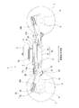
- FIG. 1 is a side view of a railway vehicle carriage 1 according to an embodiment.
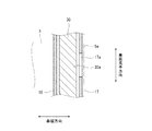
- FIG. 2 is a horizontal sectional view of an essential part of the carriage 1 shown in FIG.
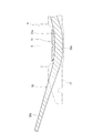
- FIG. 3 is a vertical sectional view of the main part of the carriage 1 shown in FIG.
- cover 40 mentioned later is abbreviate
- a bogie 1 for a railway vehicle includes a bogie frame 4 that supports a vehicle body via an air spring 2 and a bolster 3 that serve as a secondary suspension.
- the carriage frame 4 includes a lateral beam 5 that extends in the vehicle width direction and supports the vehicle body, but does not include a so-called side beam.
- the horizontal beam 5 is pivotably connected to the bolster 3, and the bolster 3 is connected to the vehicle body via an air spring 2 and a bolster anchor (not shown).
- a pair of axles 6 are arranged along the vehicle width direction on both sides of the transverse beam 5 in the vehicle longitudinal direction, and wheels 7 are fixed on both sides of the axle 6 in the vehicle width direction.
- Bearings 8 are provided at both ends of the axle 6 in the vehicle width direction so as to rotatably support the axle 6 outside the wheels 7 in the vehicle width direction.
- the bearings 8 are accommodated in the axle box 9.
- the pair of front and rear axle boxes 9 that are spaced apart in the longitudinal direction of the vehicle support both end portions 30b of the leaf spring 30 that extends in the longitudinal direction of the vehicle.
- a central portion 30 a in the longitudinal direction of the leaf spring 30 supports an end portion 5 a in the vehicle width direction of the cross beam 5. That is, the leaf spring 30 has both a primary suspension function and a conventional side beam function.
- the leaf spring 30 is made of, for example, fiber reinforced resin.
- the leaf spring 30 is formed in a bow shape that protrudes downward as a whole in a side view.
- the central portion 30a of the leaf spring is positioned below the both end portions 30b and has a circular arc shape protruding downward.
- the carriage frame 4 includes a pressing member 31 provided at a lower portion of the end portion 5a of the cross beam 5, and a pair of side walls protruding from the end portion 5a of the horizontal beam 5 on both sides in the vehicle width direction of the pressing member 31 and on both sides in the vehicle longitudinal direction. 17 and 18.
- the central portion 30 a of the leaf spring 30 is located below the pressing member 31.
- the leaf spring 30 passes through a space between the pair of side walls 17 and 18 in the vehicle longitudinal direction.
- the leaf spring 30 is disposed with a gap in the vehicle width direction from the side walls 17 and 18.
- the central portion 30a of the leaf spring 30 is disposed at a position overlapping the side walls 17 and 18 in a side view.
- the pressing member 31 has an arc-shaped lower surface 31a, and the pressing member 31 is placed on the central portion 30a of the leaf spring 30 from above.
- the pressing member 31 presses the upper surface of the leaf spring 30 so as to be separated by a downward load due to gravity from the cross beam 5 in a state where it is not fixed to the leaf spring 30. That is, the pressing member 31 presses the upper surface of the leaf spring 30 without being connected to the leaf spring 30 by a fixture (for example, a bolt or the like). In other words, the pressing force of the pressing member 31 against the upper surface of the leaf spring 30 is maintained by the downward load due to gravity from the horizontal beam 5 and the reaction force of the leaf spring 30 against the downward load.
- the leaf spring 30 can swing while changing the pressing region with respect to the lower surface 31 a of the pressing member 31.
- the bogie frame 4 may be placed directly on the upper surface of the central portion 30a of the leaf spring 30 or may be placed indirectly.
- a buffer sheet may be interposed between the pressing member 31 and the leaf spring 30.
- the upper surface of the axle box 9 is inclined toward the center in the longitudinal direction.
- a spring seat 33 is attached to the upper portion of the axle box 9, and both end portions 30b of the leaf spring 30 are placed on the spring seat 33 from above. That is, both end portions 30 b of the leaf spring 30 are supported by the axle box 9 via the spring seat 33.
- the spring seat 33 includes an elastic body 35 (for example, laminated rubber) positioned on the upper surface of the axle box 9 and a receiving member 36 positioned on the elastic body 35 and on which both end portions 30b of the leaf spring 30 are placed. Prepare. Both end portions 30b of the leaf spring 30 are inclined in a direction in which the upper surfaces thereof face the central portion 30a.
- the shaft box 9 is provided with a shaft beam 16 protruding from the shaft box 9 toward the center of the carriage in the longitudinal direction of the vehicle.
- a cylindrical portion 21 whose inner peripheral surface is cylindrical and whose both sides in the vehicle width direction are open is provided at the distal end portion of the shaft beam 16, and a mandrel is inserted into the inner space of the cylindrical portion 21 via a rubber bush (not shown). 22 is inserted.
- the side walls 17 and 18 are formed with insertion grooves 17c that open downward. Both ends of the mandrel 22 are fitted into the fitting groove 17c from below.
- the cover member 19 is fixed to the side walls 17 and 18 from below by bolts (not shown) so as to close the lower opening of the fitting groove 17c, and supports the mandrel 22 from below.
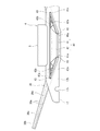
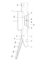
- FIG. 4 is a side view of the main part of the carriage 1 shown in FIG.
- FIG. 5 is a side view of the carriage 1 shown in FIG. 4 with the lid 40 removed.
- the central portion 30 a of the leaf spring 30 is covered by the side wall 17 from the outside in the vehicle width direction.
- the side wall 17 is formed with an opening 17 a that exposes the outer side surface of the central portion 30 a of the leaf spring 30 in the vehicle width direction.
- the opening 17a is disposed in a region included in the side surface 30c of the leaf spring 30 in a side view.
- the opening 17a is a hole that is long in the vehicle longitudinal direction.
- the opening 17a has an oval shape, and not only is used for measuring the positional deviation between the leaf spring 30 and the carriage frame 4, but also has a function as a hole for weight reduction.
- the vertical dimension of the opening 17a is smaller than the vertical thickness of the leaf spring 30, and the vehicle longitudinal dimension of the opening 17a is larger than the vertical thickness of the leaf spring 30.
- a marking M1 (for example, a punch mark) is attached to the side surface 17b of the side wall 17 on the outer side in the vehicle width direction in the vicinity of the opening 17a. Specifically, the marking M1 is provided below the opening 17a. The marking M1 is provided at the center of the carriage frame 4 in the vehicle longitudinal direction. In the present embodiment, the opening 17a is formed symmetrically with respect to the center in the vehicle longitudinal direction of the carriage frame 4 in a side view, and the marking M1 is provided at the same position as the center of the opening 17a in the vehicle longitudinal direction.
- the side surface 30c on the outer side in the vehicle width direction of the leaf spring 30 has a plurality of colored portions 30d and 30e.
- the first colored portion 30d and the second colored portion 30e are each coated so as to extend along the longitudinal direction of the leaf spring 30.
- the first coloring unit 30d has a first color
- the second coloring unit 30e has a second color different from the first color.
- the first color is a dark color (for example, black, amber, etc.) with a lightness of 0% to less than 50%
- the second color is a light color (for example, red, blue, etc.) with a lightness of 50% to 100%. , Green, etc.).
- a marking M2 (for example, a ruled line extending in the vertical direction) is attached at the longitudinal center of the leaf spring 30. In a state where the lid 40 is removed, the marking M2 is visually recognized from the outside in the vehicle width direction of the side wall 17 through the opening 17a.
- the side wall 17 has a first color on the outer side surface 17b in the vehicle width direction. That is, the side surface 17 b of the side wall 17 has the same color as the first colored portion 30 d of the leaf spring 30.
- An attachment hole 17 d for attaching the lid 40 is formed at a predetermined location on the side wall 17, and the opening 17 a is closed by the lid 40 attached to the side wall 17.
- the lid 40 is disposed so as to overlap the leaf spring 30 via the side surface 17b in a side view.
- the lid 40 has an area that is twice or more the area of the opening 17a when viewed from the outside in the vehicle width direction.
- the lid 40 has a shape in which the vehicle longitudinal dimension is longer than the vertical dimension.
- the lid 40 has a first plate 41 and a second plate 42.
- the first plate 41 has a mounting hole 41 a that matches the mounting hole 17 d of the side wall 17.
- the second plate 42 is joined to the first plate 41 so as to overlap from the outside in the vehicle width direction and has a smaller area than the first plate 41. Specifically, the peripheral edge portion of the first plate 41 protrudes outward from the second plate 42, and the second plate 42 is disposed so as to avoid the mounting hole 41a.
- the outer peripheral contour of the second plate 42 has a similar shape to the outer peripheral contour of the first plate 41.
- the lid 40 is detachably fixed to the side wall 17 by inserting a fixture 43 (for example, a bolt) into the mounting holes 17d and 41a.
- the first plate 41 and the second plate 42 have different colors.
- the outer surface of the first plate 41 in the vehicle width direction has the first color. That is, the surface of the first plate 41 on the outer side in the vehicle width direction has the same color as the side surface 17 b of the side wall 17 on the outer side in the vehicle width direction and the first colored portion 30 d of the leaf spring 30.
- the outer surface of the second plate 42 in the vehicle width direction has a second color. That is, the second plate 42 has the same color as the second colored portion 30 e of the leaf spring 30.
- the end portions 42a on both sides of the second plate 42 in the longitudinal direction of the vehicle extend in a tapered manner toward the direction in which the leaf spring 30 extends. That is, the region of the lid 40 having the same color as the second colored portion 30e of the leaf spring 30 extends toward a portion of the leaf spring 30 exposed to the outside of the side wall 17 in a side view.
- the end 42a of the second plate 42 is disposed at a position overlapping the leaf spring 30 via the side surface 17b in a side view.
- a plurality of holes 42b are formed in the end portion 42a of the second plate 42, and the first plate 41 is visible through the holes 42b.
- the measuring jig 50 has a vertical portion 50a extending in the vertical direction along the side surface 17b of the side wall 17, and a horizontal portion 50b extending inward in the vehicle width direction from the upper end of the vertical portion 50a, and has an L shape as a whole.
- the horizontal portion 50b of the measuring jig 50 has a flat contact surface 50c that makes surface contact with the side surface 30c of the leaf spring 30 and a flat placement surface 50d that is placed on the flat portion 17aa on the peripheral surface that defines the opening 17a.
- the measurement jig 50 has a measurement surface 50e which is formed continuously from the vertical portion 50a to the horizontal portion 50b and is a vertical surface with a normal line directed in the vehicle longitudinal direction.
- the operator places the measuring jig 50 in a state of being inserted into the opening 17a so as to extend from the side surface 17b of the side wall 17 to the side surface 30c of the leaf spring 30. That is, the horizontal portion 50b is inserted into the opening 17a with the vertical portion 50a of the measurement jig 50 being along the side surface 17b of the side wall 17 in the vehicle width direction outside, and the contact surface 50c is outside the plate spring 30 in the vehicle width direction. The surface 30c is brought into surface contact. At this time, the operator matches the measurement surface 50e of the measurement jig 50 with the marking M2 extending in the vertical direction of the leaf spring 30.
- the operator measures the distance in the longitudinal direction of the vehicle (that is, misalignment) between the measurement surface 50 e of the measurement jig 50 and the center of the marking M 1 on the side wall 17 using the scale 51. Thereby, the positional deviation in the vehicle longitudinal direction between the marking M2 of the leaf spring 30 and the marking M1 of the side wall 17 is measured.
- the operator displaces the leaf spring 30 with respect to the carriage frame 4 in the vehicle longitudinal direction to reduce the positional deviation (adjustment process). Then, if it is confirmed that the positional deviation in the vehicle longitudinal direction between the marking M1 of the leaf spring 30 and the marking M2 of the side wall 17 is within the allowable range, the lid 40 is attached to the side wall 17, The opening 17a is closed (lid attachment process).
- the positional deviation in the vehicle longitudinal direction between the leaf spring 30 and the bogie frame 4 can be measured easily and directly by using the opening 17 a of the side wall 17 of the bogie frame 4. Therefore, in the configuration in which the side wall 17 of the carriage frame 4 covers the leaf spring 30 from the outside in the vehicle width direction, both the assembly workability and the assembly accuracy of the carriage 1 can be improved.
- the cart 1 of the present embodiment is configured such that the plate spring 30 is not fixed to the cart frame 4, and errors are likely to occur in the relative positional relationship in the vehicle longitudinal direction between the cart frame 4 and the plate spring 30 during assembly. For this reason, the above-described aspect is effective.
- the lid 40 includes a first plate 41 fixed to the side wall 17 and a second plate 42 having a smaller area than the first plate 41 and having a color different from that of the first plate 41. By overlapping the first plate 41, the color-coded lid 40 can be easily realized. Further, since the second plate 42 of the lid 40 has the same color as the second colored portion 30e of the leaf spring 30, even if the central portion 30a of the leaf spring 30 is covered with the side wall 17, A sense of unity with the bogie frame 4 can be produced.
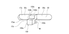
- FIG. 7 is a drawing of a modification of the measuring jig 50 shown in FIG. In FIG. 7, the scale 51 is not shown.
- the measuring jig 150 includes a first vertical portion 150a extending in the vertical direction along the side surface 17b of the side wall 17, and a horizontal portion 150b extending inward in the vehicle width direction from the upper end of the first vertical portion 150a. And a second vertical portion 150c extending upward from the horizontal portion 150b.
- the second vertical portion 150 c has a flat contact surface 150 d that makes surface contact with the side surface 30 c of the leaf spring 30.
- the horizontal portion 150b has a flat placement surface 150e that is placed on the flat portion 17aa on the peripheral surface that defines the opening 17a.
- the measurement jig 150 has a shape having a center of gravity at a position where the measurement jig 150 is kept stationary without being held by an operator in a state where the placement surface 150e is placed on the flat portion 17aa of the opening 17a.
- the measurement of the positional deviation in the vehicle longitudinal direction between the marking M2 of the leaf spring 30 and the marking M1 of the side wall 17 is performed using the scale 51 as in FIG.
- the present invention is not limited to the above-described embodiment, and the configuration can be changed, added, or deleted.
- the markings M1 and M2 do not have to be positioned at the center of the leaf spring 30 and the carriage frame 4 in the longitudinal direction of the vehicle, and the vehicle of the leaf spring 30 when the longitudinal positions of the marking M1 and the marking M2 coincide with each other. Any configuration in which the center in the longitudinal direction and the center in the vehicle longitudinal direction of the carriage frame 4 coincide with each other is acceptable.
- the markings M1 and M2 are not limited to ruled lines or punch marks, but may have other forms (for example, notches).
- the lid 40 is not limited to a configuration in which two plates are overlapped, and may be a single plate.
- the side surface on the outer side in the vehicle width direction of the plate may be painted in the first color and the second color.
- the measurement jig and the scale may be integrated with each other.
- the leaf spring 30 has a plurality of colored portions 30d and 30e, but may be monochromatic.
- the side wall 18 on the inner side in the vehicle width direction does not have an opening facing the side surface of the central portion 30a of the leaf spring 30, but the side wall 18 may have the same structure as the side wall 17 on the outer side in the vehicle width direction.
- the cart 1 is a cart with a bolster 3, but may be a bolsterless cart.
Landscapes
- Engineering & Computer Science (AREA)
- Mechanical Engineering (AREA)
- Springs (AREA)
- Automobile Manufacture Line, Endless Track Vehicle, Trailer (AREA)
- Vibration Prevention Devices (AREA)
- A Measuring Device Byusing Mechanical Method (AREA)
- Machines For Laying And Maintaining Railways (AREA)
Abstract
鉄道車両台車の組立方法は、車両長手方向に延びた板バネを車両長手方向に離間して配置された一対の軸箱に支持させる板バネ配置工程と、開口が形成された側壁を有する台車枠を前記板バネの長手方向の中央部に上方から直接的又は間接的に載せ、前記側壁により前記板バネを車幅方向外側から覆う台車枠配置工程と、前記開口を通じて前記板バネと前記台車枠との間の車両長手方向の位置ズレを測定する測定工程と、を備える。
Description
本発明は、鉄道車両台車の組立方法、測定治具及び鉄道車両台車に関する。
特許文献1では、鉄道車両台車の台車枠のうち側梁の部分を省いた台車が提案されている。当該台車では、前後一対の軸箱が車両長手方向に延びた板バネの両端部を支持し、板バネの中央部が台車枠の横梁を支持する。即ち、板バネが、一次サスペンションの機能と従来の側梁の機能とを兼ねている。そして、台車枠は、横梁の端部から突出して軸梁が連結される一対の受け座を有し、板バネは、一対の受け座で挟まれた空間を通過している。そのため、一対の受け座は、板バネの長手方向の中央部を車幅方向から覆う役目も果たす。
ところで、板バネを設計通りに機能させるには、板バネの車両長手方向のセンターと台車枠の車両長手方向のセンターとを一致させる必要がある。
しかし、板バネの車両長手方向の中央部は、台車枠の受け座(側壁)により車幅方向外側から覆われているため、センター同士が一致しているか否かを直接確認するには、組立作業者が台車の下方に潜り込んで板バネを下方から覗き込む必要があり、作業性が悪い。
また、軸箱の上端部に設けられた受け部材と板バネの長手方向の端部との間の位置ズレを確認することで、センター同士の位置ズレを推定することも考えられるが、台車枠と受け部材との間の位置関係には組立時の累積誤差が生じ得るため、当該推定方法は正確性に欠ける。
そこで本発明は、台車枠の側壁が板バネを車幅方向外側から覆う構成において、台車の組立作業性と組立精度との両方を向上させることを目的とする。
本発明の一態様に係る鉄道車両台車の組立方法は、車両長手方向に延びた板バネを車両長手方向に離間して配置された一対の軸箱に支持させる板バネ配置工程と、開口が形成された側壁を有する台車枠を前記板バネの長手方向の中央部に上方から直接的又は間接的に載せ、前記側壁により前記板バネを車幅方向外側から覆う台車枠配置工程と、前記開口を通じて前記板バネと前記台車枠との間の車両長手方向の位置ズレを測定する測定工程と、を備える。
本発明の一態様に係る鉄道車両台車は、車両長手方向に延び、車両長手方向に離間して配置された一対の軸箱に支持される板バネと、前記板バネを車幅方向外側から覆い且つ前記板バネの側面を露出させる開口が形成された側壁を有し、前記板バネの長手方向の中央部に上方から直接的又は間接的に載せられる台車枠と、を備える。
前記方法及び構成によれば、側壁の開口を通して板バネを視認することで、板バネと台車枠との間の車両長手方向の位置ズレを簡易かつ直接的に測定できる。よって、台車枠の側壁が板バネを車幅方向外側から覆う構成において、台車の組立作業性と組立精度との両方を向上できる。
本発明によれば、台車枠の側壁が板バネを車幅方向外側から覆う構成において、台車の組立作業性と組立精度との両方を向上できる。
以下、図面を参照して実施形態を説明する。なお、以下の説明では、鉄道車両が走行する方向であって車体が延びる方向を車両長手方向とし、それに直交する横方向を車幅方向として定義する。車両長手方向は前後方向とも称し、車幅方向は左右方向とも称しえる。
図1は、実施形態に係る鉄道車両の台車1の側面図である。図2は、図1に示す台車1の要部の水平断面図である。図3は、図1に示す台車1の要部の鉛直断面図である。なお、図2では後述する蓋40の図示を省略している。図1乃至3に示すように、鉄道車両用の台車1は、二次サスペンションとなる空気バネ2及びボルスタ3を介して車体を支持する台車枠4を備える。台車枠4は、車幅方向に延びて車体を支持する横梁5を備えるが、いわゆる側梁を備えていない。
横梁5は、ボルスタ3に対して旋回可能に接続され、ボルスタ3は、空気バネ2及びボルスタアンカ(図示せず)を介して車体に接続される。横梁5の車両長手方向の両側には、車幅方向に沿って一対の車軸6が配置され、車軸6の車幅方向両側には車輪7が固定されている。車軸6の車幅方向の両端部には、車輪7よりも車幅方向外側にて車軸6を回転自在に支持する軸受8が設けられ、軸受8は軸箱9に収容されている。
車両長手方向に離間して配置された前後一対の軸箱9は、車両長手方向に延びた板バネ30の両端部30bを支持している。板バネ30の長手方向の中央部30aは、横梁5の車幅方向の端部5aを支持している。即ち、板バネ30は、一次サスペンションの機能と従来の側梁の機能とを兼ねる。板バネ30は、例えば、繊維強化樹脂で形成される。板バネ30は、側面視で全体として下方に凸な弓形状に形成されている。板バネの中央部30aは、両端部30bよりも下方に位置し、下方に凸な円弧形状である。
台車枠4は、横梁5の端部5aの下部に設けられた押圧部材31と、押圧部材31の車幅方向両側において横梁5の端部5aから下方かつ車両長手方向両側に突出する一対の側壁17,18とを有する。板バネ30の中央部30aは、押圧部材31の下方に位置する。板バネ30は、一対の側壁17,18で挟まれた空間を車両長手方向に通過している。板バネ30は、側壁17,18と車幅方向に隙間をあけて配置されている。板バネ30の中央部30aは、側面視で側壁17,18と重なる位置に配置されている。
押圧部材31は、円弧状の下面31aを有し、押圧部材31が板バネ30の中央部30aに上方から載せられている。押圧部材31は、板バネ30に固定されない状態で横梁5からの重力による下方荷重によって板バネ30の上面を離隔可能に押圧している。即ち、押圧部材31は、固定具(例えば、ボルト等)により板バネ30に接続されることなく、板バネ30の上面を押圧する。言い換えれば、横梁5からの重力による下方荷重とそれに対する板バネ30の反力とによって、板バネ30の上面に対する押圧部材31の押圧が保たれた状態となる。これにより、板バネ30は、押圧部材31の下面31aに対して押圧領域を変化させながら揺動することを可能にする。なお、台車枠4は、板バネ30の中央部30aの上面に直接的に載せられてもよいし、間接的に載せられてもよい。押圧部材31と板バネ30との間に緩衝シートが介装されてもよい。
軸箱9の上面は、長手方向中央側に向けて上面が傾斜している。軸箱9の上部にはバネ座33が取り付けられ、バネ座33に板バネ30の両端部30bが上方から載せられている。即ち、板バネ30の両端部30bは、バネ座33を介して軸箱9に支持されている。バネ座33は、軸箱9の上面に位置決めされた弾性体35(例えば、積層ゴム)と、弾性体35の上に位置決めされて板バネ30の両端部30bが載せられた受け部材36とを備える。板バネ30の両端部30bは、その上面が中央部30aに向く方向に傾斜している。
軸箱9には、軸箱9から台車中央側に向けて車両長手方向に突出した軸梁16が設けられている。軸梁16の先端部には、内周面が円筒形状で車幅方向両側が開口する筒状部21が設けられ、筒状部21の内部空間にゴムブッシュ(図示せず)を介して心棒22が挿通されている。側壁17,18には、下方に向けて開口する嵌入溝17cが形成されている。嵌入溝17cには、心棒22の両端部が下方から嵌入されている。カバー部材19は、嵌入溝17cの下側開口を閉鎖するようにボルト(図示せず)により下方から側壁17,18に固定され、心棒22を下方から支持している。
図4は、図1に示す台車1の要部の側面図である。図5は、図4に示す台車1の蓋40を取り外した状態の側面図である。図4及び5に示すように、板バネ30の中央部30aは、側壁17により車幅方向外側から覆われている。側壁17には、板バネ30の中央部30aの車幅方向外側の側面を露出させる開口17aが形成されている。開口17aは、側面視において、板バネ30の側面30cに包含される領域に配置される。開口17aは、車両長手方向に長い穴である。本実施形態では、開口17aは長円形状を有しており、板バネ30と台車枠4との位置ズレを測定するのに用いるだけでなく、軽量化のための孔としての機能も有する。開口17aの鉛直方向寸法は、板バネ30の鉛直方向の厚みよりも小さく、開口17aの車両長手方向寸法は、板バネ30の鉛直方向の厚みよりも大きい。
側壁17の車幅方向外側の側面17bには、開口17aの近傍にマーキングM1(例えば、ポンチ印)が付されている。具体的には、マーキングM1は、開口17aの下側に設けられている。マーキングM1は、台車枠4の車両長手方向の中心に設けられている。本実施形態では、開口17aは、側面視において台車枠4の車両長手方向の中心を基準として対称に形成され、マーキングM1は、車両長手方向において開口17aの中心と同じ位置に設けられている。
板バネ30の車幅方向外側の側面30cは、複数の着色部30d,30eを有する。本実施形態では、第1着色部30d及び第2着色部30eは、それぞれ板バネ30の長手方向に沿って延びるように塗装されている。第1着色部30dは、第1色を有し、第2着色部30eは、第1色とは異なる第2色を有する。例えば、第1色は、明度が0%以上50%未満の暗色(例えば、黒色、紺色等)であり、第2色は、明度が50%以上100%以下の明色(例えば、赤、青、緑等)である。板バネ30の中央部30aの側面には、板バネ30の長手方向中心にてマーキングM2(例えば、鉛直方向に延びた罫書き線)が付されている。蓋40が取り外された状態では、マーキングM2が、開口17aを通して側壁17の車幅方向外側から視認される。
側壁17は、その車幅方向外側の側面17bにおいて第1色を有する。即ち、側壁17の側面17bは、板バネ30の第1着色部30dと同じ色を有する。側壁17には、蓋40を取り付けるための取付孔17dが所定箇所に形成され、側壁17に取り付けられた蓋40により開口17aが閉鎖される。蓋40は、側面視において、側面17bを介して板バネ30と重なるように配置されている。蓋40は、車幅方向外側から見て、開口17aの面積の2倍以上の面積を有する。蓋40は、鉛直方向寸法よりも車両長手方向寸法が長い形状を有する。
蓋40は、第1プレート41及び第2プレート42を有する。第1プレート41は、側壁17の取付孔17dと合致する取付孔41aを有する。第2プレート42は、第1プレート41に車幅方向外側から重ねて接合され、第1プレート41よりも面積が小さい。具体的には、第1プレート41の周縁部は、第2プレート42より外側に食み出ており、第2プレート42は、取付孔41aを避けて配置されている。第2プレート42の外周輪郭は、第1プレート41の外周輪郭と相似形状を有する。蓋40は、固定具43(例えば、ボルト)が取付孔17d,41aに挿入されることで側壁17に着脱可能に固定される。
第1プレート41と第2プレート42とは、互いに異なる色を有する。第1プレート41の車幅方向外側の表面は、第1色を有する。即ち、第1プレート41の車幅方向外側の表面は、側壁17の車幅方向外側の側面17bと板バネ30の第1着色部30dと同じ色を有する。第2プレート42の車幅方向外側の表面は、第2色を有する。即ち、第2プレート42は、板バネ30の第2着色部30eと同じ色を有する。
第2プレート42の車両長手方向両側の端部42aは、板バネ30が延びる方向に向かって先細り状に延びている。即ち、蓋40のうち板バネ30の第2着色部30eと同じ色を有する領域は、側面視において、板バネ30のうち側壁17の外側に露出した部分に向けて延びている。第2プレート42の端部42aは、側面視において、側面17bを介して板バネ30と重なる位置に配置されている。第2プレート42の端部42aには、複数の穴42bが形成されており、当該穴42bを通して第1プレート41が視認可能になっている。
次に、台車1の組立手順のうち特徴的な事項について説明する。作業者は、台車枠4の無い状態で、車両長手方向に離間して配置された一対の軸箱9上の各受け部材36に板バネ30の両端部30bを上方から載せる(板バネ配置工程)。次いで、作業者は、蓋40の付いていない台車枠4を板バネ30に載せる(台車枠配置工程)。その際、一対の側壁17,18が板バネ30の中央部30aの車幅方向両側に配置され、台車枠4の押圧部材31が板バネ30の中央部30aの上面に載せられる。それにより、板バネ30の中央部30aは、車幅方向外側から側壁17により覆われる。
次いで、図6に示すように、作業者は、測定治具50及びスケール51を用いて、板バネ30と台車枠4との間の車両長手方向の位置ズレを測定する(測定工程)。測定治具50は、側壁17の側面17bに沿って鉛直方向に延びる鉛直部50aと、鉛直部50aの上端から車幅方向内方に延びる水平部50bとを有し、全体としてL字形状を呈する。測定治具50の水平部50bは、板バネ30の側面30cに面接触させる平坦な当接面50cと、開口17aを画定する周面の平坦部17aaに載せる平坦な載置面50dとを有する。測定治具50は、鉛直部50aから水平部50bまで連続して形成されて、法線が車両長手方向に向けられた鉛直面である測定面50eを有する。
作業者は、測定治具50を、側壁17の側面17bから板バネ30の側面30cまで延びるように開口17aに挿通された状態に配置する。即ち、測定治具50の鉛直部50aを側壁17の車幅方向外側の側面17bに沿わせた状態で水平部50bを開口17aに挿通し、当接面50cを板バネ30の車幅方向外側の側面30cに面接触させる。このとき、作業者は、板バネ30の鉛直方向に延びるマーキングM2に測定治具50の測定面50eを一致させる。次いで、作業者は、測定治具50の測定面50eと側壁17のマーキングM1の中心との間の車両長手方向の距離(即ち、位置ズレ)をスケール51により測定する。これにより、板バネ30のマーキングM2と側壁17のマーキングM1との間の車両長手方向の位置ズレが測定される。
次いで、その測定された位置ズレが許容範囲を超えていた場合には、作業者は、台車枠4に対して板バネ30を車両長手方向に変位させて位置ズレを減少させる(調整工程)。そして、板バネ30のマーキングM1と側壁17のマーキングM2との間の車両長手方向の位置ズレが許容範囲内に収まったことが確認されれば、蓋40を側壁17に取り付けて、側壁17の開口17aを閉鎖する(蓋取付工程)。
以上に説明した態様によれば、台車枠4の側壁17の開口17aを利用することで、板バネ30と台車枠4との間の車両長手方向の位置ズレを簡易かつ直接的に測定できる。よって、台車枠4の側壁17が板バネ30を車幅方向外側から覆う構成において、台車1の組立作業性と組立精度との両方を向上できる。特に、本実施形態の台車1は、板バネ30が台車枠4に固定されない構成であり、組立時において台車枠4と板バネ30との間の車両長手方向の相対位置関係に誤差が生じ易いため、前述した態様が効果的である。
また、側壁17の開口17aは蓋40で閉鎖されるので、鉄道車両の走行時に飛来する異物(例えば、飛石)が開口17aを通って板バネ30に衝突することを防止できる。また、蓋40は、側壁17に固定される第1プレート41と、第1プレート41よりも面積が小さく且つ第1プレート41と異なる色を有する第2プレート42とを備えるので、第2プレート42を第1プレート41に重ねることで、色分けされた蓋40を簡単に実現できる。また、蓋40の第2プレート42が板バネ30の第2着色部30eと同じ色を有するので、板バネ30の中央部30aが側壁17で覆われた構成であっても、板バネ30と台車枠4との美観上の一体感を演出できる。
図7は、図6に示す測定治具50の変形例の図面である。なお、図7ではスケール51の図示を省略している。図7に示すように、測定治具150は、側壁17の側面17bに沿って鉛直方向に延びる第1鉛直部150aと、第1鉛直部150aの上端から車幅方向内方に延びる水平部150bと、水平部150bから上方に延びる第2鉛直部150cとを有する。第2鉛直部150cは、板バネ30の側面30cに面接触させる平坦な当接面150dを有する。水平部150bは、開口17aを画定する周面の平坦部17aaに載せる平坦な載置面150eを有する。測定治具150は、載置面150eを開口17aの平坦部17aaに載せた状態にて、作業者が保持せずとも測定治具150の静止が維持される位置に重心を有する形状である。板バネ30のマーキングM2と側壁17のマーキングM1との間の車両長手方向の位置ズレの測定は、図6と同様にスケール51を用いて行われる。
なお、本発明は前述した実施形態に限定されるものではなく、その構成を変更、追加、又は削除することができる。例えば、マーキングM1,M2は、板バネ30及び台車枠4の車両長手方向中心に位置しなくてもよく、マーキングM1とマーキングM2との車両長手方向位置が一致したときに、板バネ30の車両長手方向中心と台車枠4の車両長手方向中心とが一致する構成であればよい。マーキングM1,M2は、罫書き線又はポンチ印に限られず、他の形態(例えば、ノッチ)でもよい。蓋40は、2つのプレートを重ね合わせる構成に限られず、1つのプレートであってもよい。蓋が1つのプレートである場合、当該プレートの車幅方向外側の側面が、前述した第1色と第2色とに色分けして塗装されたものとしてもよい。測定治具50,150とスケール51とが別体となった構成を例示したが、測定治具とスケールとを互いに一体化させてもよい。板バネ30は、複数の着色部30d、30eを有していたが、単色であってもよい。図2では、車幅方向内側の側壁18には板バネ30の中央部30aの側面に対向する開口が形成されていないが、当該側壁18も車幅方向外側の側壁17と同様の構造としてもよい。台車1は、ボルスタ3付きの台車としたが、ボルスタレス台車でもよい。
1 台車
4 台車枠
9 軸箱
17 側壁
17a 開口
17b 側面
30 板バネ
30a 中央部
30c 側面
40 蓋
41 第1プレート
42 第2プレート
50,150 測定治具
M1,M2 マーキング
4 台車枠
9 軸箱
17 側壁
17a 開口
17b 側面
30 板バネ
30a 中央部
30c 側面
40 蓋
41 第1プレート
42 第2プレート
50,150 測定治具
M1,M2 マーキング
Claims (10)
- 車両長手方向に延びた板バネを車両長手方向に離間して配置された一対の軸箱に支持させる板バネ配置工程と、
開口が形成された側壁を有する台車枠を前記板バネの長手方向の中央部に上方から直接的又は間接的に載せ、前記側壁により前記板バネを車幅方向外側から覆う台車枠配置工程と、
前記開口を通じて前記板バネと前記台車枠との間の車両長手方向の位置ズレを測定する測定工程と、を備える、鉄道車両台車の組立方法。 - 前記測定工程では、前記側壁の車幅方向外側の側面に沿わせた状態で前記開口を通じて前記板バネの車幅方向外側の側面に当接可能な測定治具を用いて、前記側壁の前記側面に付されたマーキングと、前記板バネの前記側面に付されたマーキングとの間の車両長手方向の位置ズレを測定する、請求項1に記載の鉄道車両台車の組立方法。
- 前記測定された位置ズレが許容範囲を超えていた場合に、前記台車枠及び前記板バネを車両長手方向に相対変位させて前記位置ズレを減少させる調整工程を更に備える、請求項1又は2に記載の鉄道車両台車の組立方法。
- 前記開口を閉鎖する蓋を前記台車枠に取り付ける蓋取付工程を更に備える、請求項1乃至3のいずれか1項に記載の鉄道車両台車の組立方法。
- 車両長手方向に延び、車両長手方向に離間して配置された一対の軸箱に支持される板バネと、前記板バネを車幅方向外側から覆い且つ前記板バネの側面を露出させる開口が形成された側壁を有する台車枠との位置ズレを測定するための測定治具であって、
前記板バネの側面に面接触する当接面と、
その法線が車両長手方向に向けられた鉛直面である測定面と、を備える、測定治具。 - 前記台車枠の前記開口を画定する平坦部に載せられる載置面を更に備える、請求項5に記載の測定治具。
- 車両長手方向に延び、車両長手方向に離間して配置された一対の軸箱に支持される板バネと、
前記板バネを車幅方向外側から覆い且つ前記板バネの側面を露出させる開口が形成された側壁を有し、前記板バネの長手方向の中央部に上方から直接的又は間接的に載せられる台車枠と、を備える、鉄道車両台車。 - 前記台車枠に取り付けられ、前記開口を閉鎖する蓋を更に備える、請求項7に記載の鉄道車両台車。
- 前記蓋は、前記側壁に着脱可能に固定される第1プレートと、前記第1プレートに車幅方向外側から重ねられ、前記第1プレートよりも面積が小さい第2プレートとを有し、
前記第1プレートと前記第2プレートとは、互いに異なる色を有する、請求項8に記載の鉄道車両台車。 - 前記側壁は、その車幅方向外側の側面に第1色を有し、
前記板バネは、その前記側壁よりも車両長手方向外側に延びる部分の車幅方向外側の側面に前記第1色とは異なる色である第2色を有し、
前記蓋は、その車幅方向外側の側面に前記第2色を有する、請求項8又は9に記載の鉄道車両台車。
Priority Applications (3)
| Application Number | Priority Date | Filing Date | Title |
|---|---|---|---|
| CN201780029935.4A CN109195852B (zh) | 2016-05-16 | 2017-03-21 | 铁道车辆转向架的装配方法、测定治具及铁道车辆转向架 |
| SG11201810127YA SG11201810127YA (en) | 2016-05-16 | 2017-03-21 | Method of assembling railcar bogie, measurement jig, and railcar bogie |
| US16/302,597 US11104360B2 (en) | 2016-05-16 | 2017-03-21 | Method of assembling railcar bogie, measurement jig, and railcar bogie |
Applications Claiming Priority (2)
| Application Number | Priority Date | Filing Date | Title |
|---|---|---|---|
| JP2016-098098 | 2016-05-16 | ||
| JP2016098098A JP6944765B2 (ja) | 2016-05-16 | 2016-05-16 | 鉄道車両台車の組立方法、測定治具及び鉄道車両台車 |
Publications (1)
| Publication Number | Publication Date |
|---|---|
| WO2017199573A1 true WO2017199573A1 (ja) | 2017-11-23 |
Family
ID=60325782
Family Applications (1)
| Application Number | Title | Priority Date | Filing Date |
|---|---|---|---|
| PCT/JP2017/011269 Ceased WO2017199573A1 (ja) | 2016-05-16 | 2017-03-21 | 鉄道車両台車の組立方法、測定治具及び鉄道車両台車 |
Country Status (6)
| Country | Link |
|---|---|
| US (1) | US11104360B2 (ja) |
| JP (1) | JP6944765B2 (ja) |
| CN (1) | CN109195852B (ja) |
| SG (1) | SG11201810127YA (ja) |
| TW (1) | TWI655127B (ja) |
| WO (1) | WO2017199573A1 (ja) |
Families Citing this family (5)
| Publication number | Priority date | Publication date | Assignee | Title |
|---|---|---|---|---|
| JP6506630B2 (ja) * | 2015-06-03 | 2019-04-24 | 川崎重工業株式会社 | 板バネユニット及び鉄道車両用台車 |
| JP6510938B2 (ja) * | 2015-09-10 | 2019-05-08 | 川崎重工業株式会社 | 鉄道車両用台車の電極付き板バネの製造方法 |
| JP6595905B2 (ja) * | 2015-12-25 | 2019-10-23 | 川崎重工業株式会社 | 鉄道車両用台車の輪重調整具、それを備えた鉄道車両用台車、及び鉄道車両用台車の製造方法 |
| JP6530806B1 (ja) * | 2017-12-26 | 2019-06-12 | 川崎重工業株式会社 | 鉄道車両用台車 |
| CN116045762B (zh) * | 2023-02-14 | 2026-03-03 | 一汽解放汽车有限公司 | 悬架检具和装配偏差检测方法 |
Citations (3)
| Publication number | Priority date | Publication date | Assignee | Title |
|---|---|---|---|---|
| JP2003139637A (ja) * | 2001-10-30 | 2003-05-14 | Nagano Keiki Co Ltd | 歪み検出素子の製造方法 |
| WO2011034011A1 (ja) * | 2009-09-15 | 2011-03-24 | シャープ株式会社 | 蒸着方法および蒸着装置 |
| WO2013008468A1 (ja) * | 2011-07-14 | 2013-01-17 | 川崎重工業株式会社 | 鉄道車両用台車 |
Family Cites Families (14)
| Publication number | Priority date | Publication date | Assignee | Title |
|---|---|---|---|---|
| US4108080A (en) * | 1975-04-29 | 1978-08-22 | Acf Industries, Incorporated | Railway car truck and side bearing assembly |
| DE4134597C1 (ja) * | 1991-10-18 | 1992-12-10 | Krupp Brueninghaus Gmbh, 5980 Werdohl, De | |
| US5238333A (en) * | 1992-07-23 | 1993-08-24 | Acf Industries, Incorporated | Pneumatic outlet for railcars |
| US5481986A (en) * | 1994-11-09 | 1996-01-09 | Amsted Industries Incoporated | Lightweight truck sideframe |
| FR2780016B1 (fr) * | 1998-06-18 | 2000-08-04 | Alsthom Gec | Bogie de vehicule ferroviaire et procede de fabrication d'un longeron d'un tel bogie |
| CN201149476Y (zh) * | 2007-11-15 | 2008-11-12 | 泰安科诺型钢股份有限公司 | 多用测量尺 |
| JP5433080B2 (ja) * | 2011-04-07 | 2014-03-05 | 川崎重工業株式会社 | 鉄道車両用台車 |
| JP5947590B2 (ja) | 2011-07-14 | 2016-07-06 | 川崎重工業株式会社 | 鉄道車両用台車 |
| US8844447B2 (en) * | 2012-02-29 | 2014-09-30 | Electro-Motive Diesel, Inc. | Frame for railway truck |
| JP5878791B2 (ja) * | 2012-02-29 | 2016-03-08 | 川崎重工業株式会社 | 板バネユニット及びそれを用いた鉄道車両用台車 |
| JP5779280B2 (ja) * | 2012-04-06 | 2015-09-16 | 川崎重工業株式会社 | 鉄道車両用台車 |
| CN203031591U (zh) * | 2012-11-06 | 2013-07-03 | 沪东中华造船(集团)有限公司 | 多功能测量和划线工具 |
| JP6068984B2 (ja) * | 2013-01-10 | 2017-01-25 | 川崎重工業株式会社 | 鉄道車両用台車 |
| CN204432672U (zh) * | 2014-12-25 | 2015-07-01 | 太原轨道交通装备有限责任公司 | 一种适用于高铁施工运输材料的专用轨道平车转向架 |
-
2016
- 2016-05-16 JP JP2016098098A patent/JP6944765B2/ja active Active
-
2017
- 2017-03-21 US US16/302,597 patent/US11104360B2/en active Active
- 2017-03-21 WO PCT/JP2017/011269 patent/WO2017199573A1/ja not_active Ceased
- 2017-03-21 CN CN201780029935.4A patent/CN109195852B/zh active Active
- 2017-03-21 SG SG11201810127YA patent/SG11201810127YA/en unknown
- 2017-03-28 TW TW106110316A patent/TWI655127B/zh active
Patent Citations (3)
| Publication number | Priority date | Publication date | Assignee | Title |
|---|---|---|---|---|
| JP2003139637A (ja) * | 2001-10-30 | 2003-05-14 | Nagano Keiki Co Ltd | 歪み検出素子の製造方法 |
| WO2011034011A1 (ja) * | 2009-09-15 | 2011-03-24 | シャープ株式会社 | 蒸着方法および蒸着装置 |
| WO2013008468A1 (ja) * | 2011-07-14 | 2013-01-17 | 川崎重工業株式会社 | 鉄道車両用台車 |
Also Published As
| Publication number | Publication date |
|---|---|
| CN109195852B (zh) | 2020-10-13 |
| JP2017206059A (ja) | 2017-11-24 |
| US20190291753A1 (en) | 2019-09-26 |
| TW201803757A (zh) | 2018-02-01 |
| CN109195852A (zh) | 2019-01-11 |
| US11104360B2 (en) | 2021-08-31 |
| SG11201810127YA (en) | 2018-12-28 |
| JP6944765B2 (ja) | 2021-10-06 |
| TWI655127B (zh) | 2019-04-01 |
Similar Documents
| Publication | Publication Date | Title |
|---|---|---|
| JP6944765B2 (ja) | 鉄道車両台車の組立方法、測定治具及び鉄道車両台車 | |
| KR101741092B1 (ko) | 철도 차량용 대차 | |
| JP5883488B2 (ja) | 鉄道車両用台車 | |
| JP6178299B2 (ja) | 鉄道車両用台車及び鉄道車両 | |
| US4274339A (en) | Radially steering railway truck assembly | |
| EP3984854A1 (en) | Bogie | |
| JP6560836B2 (ja) | 鉄道車両用台車 | |
| JP6751361B2 (ja) | 鉄道車両用台車 | |
| JP5710376B2 (ja) | 鉄道車両 | |
| WO2022120966A1 (zh) | 转向架侧梁、转向架及轨道车辆 | |
| KR101581417B1 (ko) | 차량 사이드 바디용 검사 테이블 장치 | |
| US20190009800A1 (en) | Wheel load adjusting tool of railcar bogie, railcar bogie including the same, and method of manufacturing railcar bogie | |
| KR101844145B1 (ko) | 철도차량 완성 대차 도장용 가대차 | |
| TWI681891B (zh) | 鐵道車輛用台車的支持構造及支持方法 | |
| CN207494832U (zh) | 工矿电机车轴箱方孔的组对工装 | |
| US20200269886A1 (en) | Method of assembling railcar bogie and wheel base fixing jig for use therein | |
| JPH05131801A (ja) | 鉄道車両用輪軸 | |
| JPS5843490Y2 (ja) | ボルスタレス型ボギ−車の改良台車 | |
| IL259365A (en) | Swivel cylinder repair device of a boogie magnetic shoe of a vehicle on a rail, a boogie and a vehicle on a tied rail | |
| WO2025234384A1 (ja) | 鉄道車両の台車の軸箱支持装置 | |
| KR100482597B1 (ko) | 스티어링 휠 센터링 설정장치 | |
| CN103889809A (zh) | 具有用于悬架的适配器的铁路转向架组件 |
Legal Events
| Date | Code | Title | Description |
|---|---|---|---|
| NENP | Non-entry into the national phase |
Ref country code: DE |
|
| 121 | Ep: the epo has been informed by wipo that ep was designated in this application |
Ref document number: 17799007 Country of ref document: EP Kind code of ref document: A1 |
|
| 122 | Ep: pct application non-entry in european phase |
Ref document number: 17799007 Country of ref document: EP Kind code of ref document: A1 |