WO2017195836A1 - ファンシュラウド - Google Patents
ファンシュラウド Download PDFInfo
- Publication number
- WO2017195836A1 WO2017195836A1 PCT/JP2017/017732 JP2017017732W WO2017195836A1 WO 2017195836 A1 WO2017195836 A1 WO 2017195836A1 JP 2017017732 W JP2017017732 W JP 2017017732W WO 2017195836 A1 WO2017195836 A1 WO 2017195836A1
- Authority
- WO
- WIPO (PCT)
- Prior art keywords
- upstream
- downstream
- opening
- fan shroud
- openings
- Prior art date
- Legal status (The legal status is an assumption and is not a legal conclusion. Google has not performed a legal analysis and makes no representation as to the accuracy of the status listed.)
- Ceased
Links
Images



Classifications
-
- F—MECHANICAL ENGINEERING; LIGHTING; HEATING; WEAPONS; BLASTING
- F04—POSITIVE - DISPLACEMENT MACHINES FOR LIQUIDS; PUMPS FOR LIQUIDS OR ELASTIC FLUIDS
- F04D—NON-POSITIVE-DISPLACEMENT PUMPS
- F04D29/00—Details, component parts, or accessories
- F04D29/40—Casings; Connections of working fluid
- F04D29/52—Casings; Connections of working fluid for axial pumps
- F04D29/54—Fluid-guiding means, e.g. diffusers
-
- F—MECHANICAL ENGINEERING; LIGHTING; HEATING; WEAPONS; BLASTING
- F04—POSITIVE - DISPLACEMENT MACHINES FOR LIQUIDS; PUMPS FOR LIQUIDS OR ELASTIC FLUIDS
- F04D—NON-POSITIVE-DISPLACEMENT PUMPS
- F04D29/00—Details, component parts, or accessories
- F04D29/66—Combating cavitation, whirls, noise, vibration or the like; Balancing
Definitions
- the present disclosure relates to a fan shroud that allows air to flow from an inlet to an outlet.
- Patent Literature 1 The thing of the following patent document 1 is known as a fan shroud which flows air from a suction inlet to a blower outlet.
- the fan shroud described in Patent Literature 1 below is applied to a vehicle cooling system, and a propeller fan is housed in a bell mouth portion. By rotating the propeller fan, an air flow is generated in the fan shroud to cool the condenser and the radiator.
- the outer peripheral wall of the part containing the condenser and the radiator and the outer peripheral wall of the part containing the propeller fan In this case, a portion close to each other and a portion separated from each other are generated. Due to such morphological characteristics, when the propeller fan rotates, a portion where the air inflow is sufficiently ensured and a portion where the air inflow is not sufficiently ensured are generated, and an annoying periodic noise is generated.
- Patent Document 1 in order to solve this problem, an opening is provided in a portion where an outer peripheral wall of a portion in which a condenser or a radiator is accommodated and an outer peripheral wall of a portion in which a propeller fan is accommodated.
- the primary frequency sound is a first peak sound whose frequency is represented by NZ / 60.
- N is the number of blades of the propeller fan, and Z is the rotational speed (rpm).
- the secondary frequency sound is a second peak sound that appears at a wavelength that is approximately twice the wavelength of the primary frequency sound.
- the secondary frequency sound is higher in frequency than the primary frequency sound, it is audibly preferable that the sound pressure is lower than that of the primary frequency sound.
- the increasing secondary frequency sound is equal to or higher than the decreasing primary frequency sound, it is unnaturally perceived as an unpleasant sound.
- the present disclosure provides a fan shroud that allows air to flow from an inlet port to an outlet port, which can reduce primary frequency sound due to rotation of a propeller fan and suppress deterioration of secondary frequency sound. With the goal.
- the present disclosure is a fan shroud that allows air to flow from a suction port to a blow-out port, the bell mouth part (22) having a circular wall (221) that forms the blow-out port and accommodates a propeller fan, and the suction A rectangular portion (21) that forms a mouth and has a proximity wall (211 and 212) adjacent to the circular wall and a separation wall (213 and 214) that is separated from the circular wall rather than the proximity wall; It has.
- the proximity wall has a closest region (211a, 212a) closest to the circular wall and a pair of connection regions (211b, 211c, 212b, 212c) that sandwich the closest region and connect to the separation wall. ing.
- An opening (41, 42, 51 to 54, 41A to 43A, 51A to 53A, 41B to 43B, 51B to 53B, 41C to 43C, 51C to 53C) is provided in at least one of the pair of connection regions. The opening is not provided in the closest region.
- the opening is provided in the connection region without providing the opening in the closest region, not only the primary frequency sound but also the secondary frequency sound can be reduced.
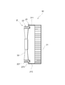
- FIG. 1 is a front view of a fan shroud according to the first embodiment.
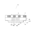
- FIG. 2 is a cross-sectional view showing a II-II cross section of FIG.
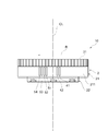
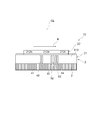
- FIG. 3 is a view taken in the direction of arrow A in FIG. 4 is a view taken in the direction of arrow B in FIG.
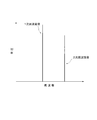
- FIG. 5 is a diagram for explaining the effect of the present embodiment.
- FIG. 6 is a plan view of a fan shroud according to the second embodiment.
- FIG. 7 is a plan view of a fan shroud according to the third embodiment.
- FIG. 8 is a plan view of a fan shroud according to the fourth embodiment.
- the fan shroud 2 according to the first embodiment is applied to a vehicle cooling system 10.
- the vehicle cooling system 10 includes a fan shroud 2, a heat exchanger 31, a propeller fan 32, and a drive motor (not shown).
- the heat exchanger 31 functions as a condenser used for an air conditioner or a radiator used for cooling a traveling engine.
- One heat exchanger 31 may function as a condenser or a radiator, or two heat exchangers 31 function as each.
- the capacitor is a device that constitutes the refrigeration cycle of the air conditioner.
- the condenser is provided with an air flow path so that the high-temperature and high-pressure refrigerant gas circulated from the compressor exchanges heat with the outside air.
- the refrigerant condensed and liquefied by heat exchange with air flows out to the downstream equipment constituting the refrigeration cycle.
- the radiator is a device that cools the cooling water of the traveling engine. Cooling water that has been heated around the combustion chamber of the engine and is heated to a radiator is circulated by a pump and sent into the radiator. The radiator is provided with an air flow path so that the high-temperature cooling water exchanges heat with the outside air. The cooling water cooled by exchanging heat with air returns to the engine and cools the engine again.
- the fan shroud 2 is provided for flowing air from the suction port to the blowout port, and is used for flowing air through the air flow path of the heat exchanger 31.
- the fan shroud 2 has a rectangular portion 21 and a bell mouth portion 22.
- the rectangular portion 21 has adjacent walls 211 and 212 that form a rectangular frame along the outer periphery of the heat exchanger 31, and separation walls 213 and 214.
- the rectangular portion 21 has a connecting plate portion 215 that connects the adjacent walls 211 and 212 and the separation walls 213 and 214.
- the bell mouth part 22 has a circular wall 221 having a cylindrical shape.
- the circular wall 221 is provided so as to stand up from the periphery of the circular opening provided in the connection plate portion 215.
- the circular wall 221 has a cylindrical shape along the outer periphery of the propeller fan 32.
- the propeller fan 32 is rotated by a drive motor and has a function of guiding air to the heat exchanger 31.
- the propeller fan 32 is housed in the bell mouth portion 22. As the propeller fan 32 rotates, an air flow passing through the heat exchanger 31 is formed.
- the heat shroud 2 side of the fan shroud 2 is an air inlet, and the bell mouth portion 22 side is an air outlet.
- the rotation direction of the propeller fan 32 is indicated as the rotation direction R.
- the proximity walls 211 and 212 are wall members provided so as to be close to the circular wall 221.
- the partition walls 213 and 214 are wall members that are provided farther from the circular wall 221 than the adjacent walls 211 and 212.
- the proximity wall 211 has a closest region 211a and a pair of connection regions 211b and 211c.
- the closest area 211 a is an area close to the circular wall 221.
- the pair of connection areas 211b and 211c are provided with the closest area 211a interposed therebetween.
- the connection region 211 b is connected to the separation partition wall 213, and the connection region 211 c is connected to the separation partition wall 214. Since the connection region 211b is disposed on the upstream side when viewed from the rotation direction R of the propeller fan 32, it corresponds to the upstream connection region of the present disclosure. Since the connection region 211c is disposed on the downstream side when viewed from the rotation direction R of the propeller fan 32, it corresponds to the downstream connection region of the present disclosure.
- the proximity wall 212 has a closest region 212a and a pair of connection regions 212b and 212c.
- the closest region 212 a is a region close to the circular wall 221.
- the pair of connection regions 212b and 212c are provided with the closest region 212a interposed therebetween.
- the connection region 212b is connected to the separation partition wall 214, and the connection region 212c is connected to the separation partition wall 213. Since the connection region 212b is disposed on the upstream side when viewed from the rotation direction R of the propeller fan 32, it corresponds to the upstream connection region of the present disclosure. Since the connection region 212c is disposed on the downstream side when viewed from the rotation direction R of the propeller fan 32, it corresponds to the downstream connection region of the present disclosure.
- the closest region 211a is not provided with an opening.
- the closest region 211 a is a nearby region including a center line CL passing through the rotation center of the propeller fan 32. Even in the closest region 211a, the center line CL is not opened.
- the connection area 211b which is the upstream connection area
- upstream divided openings 41 and 42 are provided in the connection area 211b, which is the upstream connection area.
- the upstream divided openings 41 and 42 as a whole correspond to the upstream openings of the present disclosure.
- Downstream divided openings 51, 52, 53, and 54 are provided in the connection region 211c, which is the downstream connection region.
- the downstream divided openings 51, 52, 53, 54 as a whole correspond to the downstream openings of the present disclosure.
- the upstream divided openings 41 and 42 and the downstream divided openings 51, 52, 53, and 54 are openings having the same opening area. Accordingly, the opening of the connection region 211c in which the four downstream divided openings 51, 52, 53, and 54 are provided is larger than the opening area of the connection region 211b in which the two upstream divided openings 41 and 42 are provided. Wide area.
- the closest region 212a is not provided with an opening.
- connection area 212b which is the upstream connection area.
- upstream divided openings 41 and 42 are provided in the connection area 212b.
- the upstream divided openings 41 and 42 as a whole correspond to the upstream openings of the present disclosure.
- Downstream divided openings 51, 52, 53, and 54 are provided in the connection region 212c that is the downstream connection region.
- the downstream divided openings 51, 52, 53, 54 as a whole correspond to the downstream openings of the present disclosure.
- the upstream divided openings 41 and 42 and the downstream divided openings 51, 52, 53, and 54 are openings having the same opening area. Accordingly, the connection region 212c in which the four downstream divided openings 51, 52, 53, and 54 are provided is larger than the total opening area of the connection region 212b in which the two upstream divided openings 41 and 42 are provided. The total opening area is wide.
- the fan shroud 2 allows air to flow from the suction port to the blowout port, forms a blowout port, and has a bell mouth portion having a circular wall 221 so that the propeller fan 32 can be accommodated. 22, a rectangular portion 21 having a suction port and adjacent walls 211 and 212 that are close to the circular wall 221, and separation walls 213 and 214 that are separated from the circular wall 221 rather than the adjacent walls 211 and 212, It has.
- the adjacent walls 211 and 212 include the closest regions 211a and 212a closest to the circular wall 221 and a pair of connection regions 211b, 211c, 212b, and 212c that sandwich the closest regions 211a and 212a and are connected to the separation partitions 213 and 214.
- the upstream divided openings 41 and 42 and the downstream divided openings 51, 52, 53, 54 are provided in the connection areas 211 b, 211 c, 212 b, 212 c without providing openings in the closest areas 211 a, 212 a. Since it is provided, the primary frequency sound can be reduced and deterioration of the secondary frequency sound can be suppressed. As shown in FIG. 5, the primary frequency sound increases to the broken line portion in the figure unless any countermeasure is taken, but can be reduced to the solid line portion in the figure by forming the opening as described above. it can. When the opening is provided in the closest region, the secondary frequency sound increases up to the broken line portion in the figure.
- the primary frequency sound is a first peak sound whose frequency is represented by NZ / 60.
- N is the number of blades of the propeller fan, and Z is the rotational speed (rpm).
- the secondary frequency sound is a second peak sound that appears at a wavelength that is approximately twice the wavelength of the primary frequency sound.
- the center of the rectangular portion 21 and the center of the bell mouth portion 22 are provided is described. However, the center of the bell mouth portion 22 is close to the separating partition 213 or the separating partition 214. It may be arranged to do.
- connection areas 211b and 212b are provided on the downstream side in the rotation direction R of the propeller fan 32 and the connection areas 211b and 212b as the upstream connection areas provided on the upstream side in the rotation direction R of the propeller fan 32.
- Connection areas 211c and 212c as downstream connection areas.
- the openings are provided in the upstream divided openings 41 and 42 that are upstream openings provided in the connection areas 211b and 212b as upstream connection areas, and in the connection areas 211c and 212c as downstream connection areas.
- the downstream divided openings 51, 52, 53, and 54, which are downstream openings, and the opening area of the downstream opening is wider than the opening area of the upstream opening.
- the propeller fan 32 blows air by rotation, on the downstream side in the rotation direction R, which is the direction of rotation of the propeller fan 32, from the closest areas 211a and 212a, the air traveling toward the closest areas 211a and 212a and the propeller fan 32 are opposed to each other.
- a negative pressure distribution that is biased by an increase in relative speed is considered to occur. Therefore, the uneven negative pressure distribution is smoothed by making the opening area on the downstream side in the rotation direction R, which is the direction of rotation of the propeller fan 32, larger than the opening area on the upstream side in the rotation direction. For this reason, it can contribute to suppression of the deterioration of the secondary frequency sound as shown in FIG.
- the upstream opening has a plurality of upstream divided openings 41 and 42
- the downstream opening has a plurality of downstream divided openings 51, 52, 53, and 54. Yes.
- the number of the downstream divided openings 51, 52, 53, 54 is configured to be larger than the number of the upstream divided openings 41, 42.
- the way of providing the upstream opening and the downstream opening is not limited to the above. If no opening is provided in the closest regions 211a and 212a, the upstream divided opening and the downstream divided opening are made to equalize the opening area of the upstream opening and the opening area of the downstream opening. It is good also as the same area and the same number. Further, if no opening is provided in the closest areas 211a and 212a, only one of the upstream opening and the downstream opening may be provided.
- a fan shroud 2A as a second embodiment will be described with reference to FIG. As shown in FIG. 6, the fan shroud 2A includes a rectangular portion 21A.
- the rectangular portion 21A is provided with the same number of upstream divided openings 41A, 42A, 43A and downstream divided openings 51A, 52A, 53A, respectively.
- the respective opening areas of the downstream divided openings 51A, 52A, 53A are It is spreading.
- the upstream divided openings 41A, 42A, and 43A have the same width as the downstream divided openings 51A, 52A, and 53A, and the lengths of the downstream divided openings 51A, 52A, and 53A are the same. Is set to be twice the length of the upstream divided openings 41A, 42A, 43A.
- the “width” is a dimension along the rotation direction R of the propeller fan 32, and the “length” is a dimension in a direction intersecting with the rotation direction R.
- the fan shroud 2B of the third embodiment will be described with reference to FIG. As shown in FIG. 7, the fan shroud 2B includes a rectangular portion 21B.
- the rectangular portion 21B is provided with the same number of upstream divided openings 41B, 42B, and 43B and downstream divided openings 51B, 52B, and 53B.
- the respective opening areas of the downstream divided openings 51B, 52B, and 53B are It is spreading.
- the upstream divided openings 41B, 42B, and 43B have the same length as the downstream divided openings 51B, 52B, and 53B, and the width of the downstream divided openings 51B, 52B, and 53B. Is set to be twice the width of the upstream divided openings 41B, 42B, 43B.
- the fan shroud 2C of the fourth embodiment will be described with reference to FIG.
- the fan shroud 2C includes a rectangular portion 21C.
- the rectangular portion 21C is provided with three upstream divided openings 41C, 42C, 43C and three downstream divided openings 51C, 52C, 53C.
- the upstream divided openings 41C, 42C and 43C are formed as circular openings.
- Each of the downstream divided openings 51C, 52C, 53C is formed with a pair of circular openings having the same diameter as the upstream divided openings 41C, 42C, 43C. Therefore, the total opening area of the downstream divided openings 51C, 52C, and 53C is larger than the total opening area of the upstream divided openings 41C, 42C, and 43C.
- the opening area per one of the downstream divided openings 51A to 53A, 51B to 53B, and 51C to 53C is the upstream divided opening. It can be configured to be larger than the opening area per one of the portions 41A to 43A, 41B to 43B, and 41C to 43C.
Landscapes
- Engineering & Computer Science (AREA)
- Mechanical Engineering (AREA)
- General Engineering & Computer Science (AREA)
- Structures Of Non-Positive Displacement Pumps (AREA)
Abstract
ファンシュラウド2は、円形壁を有するベルマウス部22と、円形壁に近接する近接壁211と、円形壁から離隔してなる離隔壁とを有する矩形部21と、を備えている。近接壁211は、円形壁に最も近接する最近接領域211aと、それを挟む一対の接続領域211b,211cとを有し、一対の接続領域211b,211cの少なくとも一方に内外を連通する開口部41,42,51~54が設けられ、最近接領域211aには開口部が設けられていない。
Description
本出願は、2016年5月11日に出願された日本国特許出願2016-095196号と、2017年2月20日に出願された日本国特許出願2017-029368号と、に基づくものであって、その優先権の利益を主張するものであり、その特許出願の全ての内容が、参照により本明細書に組み込まれる。
本開示は、吸込み口から吹出し口に空気を流すファンシュラウドに関する。
吸込み口から吹出し口に空気を流すファンシュラウドとして、下記特許文献1に記載のものが知られている。下記特許文献1に記載のファンシュラウドは、車両用冷却システムに適用されるものであって、プロペラファンがベルマウス部に収められている。プロペラファンを回転させることによってファンシュラウド内に空気流が発生し、コンデンサやラジエータを冷却している。
コンデンサやラジエータは外周が矩形形状をなしており、プロペラファンは外周が円形形状をなしているため、コンデンサやラジエータが収められている部分の外周壁とプロペラファンが収められている部分の外周壁とでは、互いに近接する部分と離隔する部分とが発生する。このような形態的特性により、プロペラファンが回転すると、空気流入が十分確保される部分と空気流入が十分に確保されない部分とが発生し、耳障りな周期騒音が発生する。
下記特許文献1では、この課題を解決するため、コンデンサやラジエータが収められている部分の外周壁とプロペラファンが収められている部分の外周壁とが近接する部分に開口を設けるものとしている。
本発明者らが上記特許文献1に記載されているような開口を設けたファンシュラウドを用いて、プロペラファンの回転による騒音の発生について確認を行ったところ、耳障りな騒音の発生について改善の余地があることを見出した。より具体的には、1次周波数音の低減効果は確認できたものの、2次周波数音の低減効果は確認されず、むしろ2次周波数音については増大傾向にあることを見出した。1次周波数音とは、周波数がN・Z/60で表される第1ピーク音である。尚、Nはプロペラファンの翼枚数、Zは回転数(rpm)である。2次周波数音とは、1次周波数音の波長の略倍の波長で出現する第2ピーク音である。2次周波数音は、1次周波数音に対して周波数が高いものであるため、音圧は1次周波数音に対して低くなることが聴覚的に好ましい。しかしながら、増大する2次周波数音が低下する1次周波数音と同等以上となってしまうため、聴覚的には不自然なものとなり、不快な音として認識される。
本開示は、吸込み口から吹出し口に空気を流すファンシュラウドであって、プロペラファンの回転による1次周波数音を低減し、2次周波数音の悪化を抑制することができるファンシュラウドを提供することを目的とする。
本開示は、吸込み口から吹出し口に空気を流すファンシュラウドであって、前記吹出し口を形成し、プロペラファンが収められるように円形壁(221)を有するベルマウス部(22)と、前記吸込み口を形成し、前記円形壁に近接する近接壁(211,212)と、前記近接壁よりも前記円形壁から離隔してなる離隔壁(213,214)とを有する矩形部(21)と、を備えている。前記近接壁は、前記円形壁に最も近接する最近接領域(211a,212a)と、前記最近接領域を挟み前記離隔壁に繋がる一対の接続領域(211b,211c,212b,212c)とを有している。前記一対の接続領域の少なくとも一方に内外を連通する開口部(41,42,51~54,41A~43A,51A~53A,41B~43B,51B~53B,41C~43C,51C~53C)が設けられ、前記最近接領域には前記開口部が設けられていない。
本開示によれば、最近接領域に開口部を設けずに、接続領域に開口部を設けているので、1次周波数音のみならず2次周波数音も低減することができる。
尚、「発明の概要」及び「請求の範囲」に記載した括弧内の符号は、後述する「発明を実施するための形態」との対応関係を示すものであって、「発明の概要」及び「請求の範囲」が、後述する「発明を実施するための形態」に限定されることを示すものではない。
以下、添付図面を参照しながら本実施形態について説明する。説明の理解を容易にするため、各図面において同一の構成要素に対しては可能な限り同一の符号を付して、重複する説明は省略する。
図1及び図2に示されるように、第1実施形態に係るファンシュラウド2は、車両用冷却システム10に適用されるものである。車両用冷却システム10は、ファンシュラウド2と、熱交換器31と、プロペラファン32と、図示しない駆動モータとを備えている。
熱交換器31は、空調装置に用いられるコンデンサや、走行エンジンの冷却用に用いられるラジエータとして機能する。熱交換器31は、コンデンサ又はラジエータとして機能するものを1つ配置しても、それぞれとして機能するもの2つを配置してもよい。
コンデンサは、空調装置の冷凍サイクルを構成する機器である。コンデンサには、圧縮機から循環される高温高圧の冷媒ガスを外気と熱交換させるように、空気流路が設けられている。空気と熱交換して凝縮液化した冷媒は、冷凍サイクルを構成する下流側機器へと流出する。
ラジエータは、走行エンジンの冷却水を冷却する機器である。ラジエータには、エンジンの燃焼室回りを冷却して高温となった冷却水が、ポンプによって循環されて送り込まれてくる。ラジエータには、高温の冷却水を外気と熱交換させるように、空気流路が設けられている。空気と熱交換して冷却された冷却水は、エンジンへと還流し再びエンジンを冷却する。
ファンシュラウド2は、吸込み口から吹出し口に空気を流すために設けられるものであって、熱交換器31の空気流路に空気を流すためのものである。ファンシュラウド2は、矩形部21と、ベルマウス部22とを有している。
矩形部21は、熱交換器31の外周に沿うように矩形枠を形成する近接壁211,212と、離隔壁213,214とを有している。矩形部21は、近接壁211,212と離隔壁213,214とを繋ぐ接続板部215を有している。ベルマウス部22は、円筒状をなす円形壁221を有している。円形壁221は、接続板部215に設けられた円形開口周縁から立設するように設けられている。円形壁221は、プロペラファン32の外周に沿うように円筒形状をなしている。
プロペラファン32は、駆動モータによって回転され、熱交換器31に導風する機能を有している。プロペラファン32は、ベルマウス部22内に収められている。プロペラファン32が回転することで熱交換器31を通過する空気流が形成される。ファンシュラウド2の熱交換器31側が空気の吸込み口であり、ベルマウス部22側が空気の吹出し口である。本実施形態では、プロペラファン32の回転方向を回転方向Rとして示している。
近接壁211,212は、円形壁221に近接するように設けられている壁部材である。離隔壁213,214は、近接壁211,212よりも円形壁221から離隔して設けられている壁部材である。
近接壁211は、最近接領域211aと、一対の接続領域211b,211cとを有している。最近接領域211aは、円形壁221に近接する領域である。一対の接続領域211b,211cは、最近接領域211aを挟んで設けられている。接続領域211bは離隔壁213に繋がっており、接続領域211cは、離隔壁214に繋がっている。プロペラファン32の回転方向Rからみて、接続領域211bは上流側に配置されているので、本開示の上流側接続領域に相当する。プロペラファン32の回転方向Rからみて、接続領域211cは下流側に配置されているので、本開示の下流側接続領域に相当する。
近接壁212は、最近接領域212aと、一対の接続領域212b,212cとを有している。最近接領域212aは、円形壁221に近接する領域である。一対の接続領域212b,212cは、最近接領域212aを挟んで設けられている。接続領域212bは離隔壁214に繋がっており、接続領域212cは、離隔壁213に繋がっている。プロペラファン32の回転方向Rからみて、接続領域212bは上流側に配置されているので、本開示の上流側接続領域に相当する。プロペラファン32の回転方向Rからみて、接続領域212cは下流側に配置されているので、本開示の下流側接続領域に相当する。
図3に示されるように、本実施形態では最近接領域211aには開口部が設けられていない。最近接領域211aは、プロペラファン32の回転中心を通る中心線CLを含む近傍の領域である。また、最近接領域211aであっても、中心線CLは開口していない。上流側接続領域である接続領域211bには、上流側分割開口部41,42が設けられている。上流側分割開口部41,42全体としては、本開示の上流側開口部に相当する。下流側接続領域である接続領域211cには、下流側分割開口部51,52,53,54が設けられている。下流側分割開口部51,52,53,54全体としては、本開示の下流側開口部に相当する。
上流側分割開口部41,42及び下流側分割開口部51,52,53,54は、それぞれ同じ開口面積の開口部である。従って、2つの上流側分割開口部41,42が設けられている接続領域211bの開口面積よりも、4つの下流側分割開口部51,52,53,54が設けられている接続領域211cの開口面積が広い。
図4に示されるように、本実施形態では最近接領域212aには開口部が設けられていない。上流側接続領域である接続領域212bには、上流側分割開口部41,42が設けられている。上流側分割開口部41,42全体としては、本開示の上流側開口部に相当する。下流側接続領域である接続領域212cには、下流側分割開口部51,52,53,54が設けられている。下流側分割開口部51,52,53,54全体としては、本開示の下流側開口部に相当する。
上流側分割開口部41,42及び下流側分割開口部51,52,53,54は、それぞれ同じ開口面積の開口部である。従って、2つの上流側分割開口部41,42が設けられている接続領域212bの総開口面積よりも、4つの下流側分割開口部51,52,53,54が設けられている接続領域212cの総開口面積が広い。
上記したように本実施形態に係るファンシュラウド2は、吸込み口から吹出し口に空気を流すものであって、吹出し口を形成し、プロペラファン32が収められるように円形壁221を有するベルマウス部22と、吸込み口を形成し、円形壁221に近接する近接壁211,212と、近接壁211,212よりも円形壁221から離隔してなる離隔壁213,214とを有する矩形部21と、を備えている。
近接壁211,212は、円形壁221に最も近接する最近接領域211a,212aと、最近接領域211a,212aを挟み離隔壁213,214に繋がる一対の接続領域211b,211c,212b,212cとを有している。一対の接続領域211b,211cの少なくとも一方又は一対の接続領域212b,212cの少なくとも一方に内外を連通する開口部である上流側分割開口部41,42又は下流側分割開口部51,52,53,54が設けられ、最近接領域211a,212aには開口部が設けられていない。
このように、最近接領域211a,212aに開口部を設けずに、接続領域211b,211c,212b,212cに上流側分割開口部41,42及び下流側分割開口部51,52,53,54を設けているので、1次周波数音を低減し、2次周波数音の悪化を抑制することができる。図5に示されるように、1次周波数音は、何も対策しなければ図中破線部分まで増大するところ、上記したような開口部を形成することで、図中実線部分まで低減することができる。2次周波数音は、最近接領域に開口部を設けてしまうと図中破線部分まで増大するところ、最近接領域211a,212aに開口部を設けないことで、図中実線部分に抑制することができる。従って、1次周波数音に対して2次周波数音を低く抑えることができるので、不快音の発生を抑制することができる。1次周波数音とは、周波数がN・Z/60で表される第1ピーク音である。Nはプロペラファンの翼枚数、Zは回転数(rpm)である。2次周波数音とは、1次周波数音の波長の略倍の波長で出現する第2ピーク音である。尚、本実施形態では、矩形部21の中心とベルマウス部22の中心とが重なるように設けられている例について説明したが、ベルマウス部22の中心が離隔壁213又は離隔壁214に近接するように配置されてもよい。
また本実施形態では、一対の接続領域は、プロペラファン32の回転方向R上流側に設けられている上流側接続領域としての接続領域211b,212bと、プロペラファン32の回転方向R下流側に設けられている下流側接続領域としての接続領域211c,212cとからなっている。開口部としては、上流側接続領域としての接続領域211b,212bに設けられている上流側開口部である上流側分割開口部41,42と、下流側接続領域としての接続領域211c,212cに設けられている下流側開口部である下流側分割開口部51,52,53,54とを有し、下流側開口部の開口面積が、上流側開口部の開口面積よりも広い。
プロペラファン32は回転によって送風するため、最近接領域211a,212aからプロペラファン32の回転進行方向である回転方向R下流側においては、最近接領域211a,212aに向かう空気とプロペラファン32とが対抗してしまい、相対速度の上昇によって偏った負圧分布を生じるものと思われる。そこで、プロペラファン32の回転進行方向である回転方向R下流側の開口面積を回転方向上流側の開口面積よりも広くすることで、偏った負圧分布を平滑化している。このため、図5に示されるような2次周波数音の悪化抑制に資することができる。
また本実施形態では、上流側開口部は、複数の上流側分割開口部41,42を有し、下流側開口部は、複数の下流側分割開口部51,52,53,54を有している。更に、下流側分割開口部51,52,53,54の個数が、上流側分割開口部41,42の個数よりも多くなるように構成している。
上流側開口部及び下流側開口部の設け方は、上記したものに限られない。最近接領域211a,212aに開口部を設けないのであれば、上流側開口部の開口面積と下流側開口部の開口面積とを等しくするため、上流側分割開口部と下流側分割開口部とを同面積且つ同数としてもよい。また、最近接領域211a,212aに開口部を設けないのであれば、上流側開口部及び下流側開口部のいずれか一方のみを設けてもよい。
第2実施形態としてのファンシュラウド2Aについて図6を参照しながら説明する。図6に示されるように、ファンシュラウド2Aは、矩形部21Aを備えている。矩形部21Aには、それぞれ同数の上流側分割開口部41A,42A,43Aと下流側分割開口部51A,52A,53Aとが設けられている。
上流側分割開口部41A,42A,43Aの総開口面積よりも、下流側分割開口部51A,52A,53Aの総開口面積を広げるため、下流側分割開口部51A,52A,53Aそれぞれの開口面積を広げている。具体的には、上流側分割開口部41A,42A,43Aの幅と下流側分割開口部51A,52A,53Aの幅は同一なものとしつつ、下流側分割開口部51A,52A,53Aの長さを上流側分割開口部41A,42A,43Aの長さの倍になるようにしている。尚、「幅」とは、プロペラファン32の回転方向Rに沿った寸法であり、「長さ」とは、回転方向Rに交わる方向の寸法である。
続いて、第3実施形態のファンシュラウド2Bについて図7を参照しながら説明する。図7に示されるように、ファンシュラウド2Bは、矩形部21Bを備えている。矩形部21Bには、それぞれ同数の上流側分割開口部41B,42B,43Bと下流側分割開口部51B,52B,53Bとが設けられている。
上流側分割開口部41B,42B,43Bの総開口面積よりも、下流側分割開口部51B,52B,53Bの総開口面積を広げるため、下流側分割開口部51B,52B,53Bそれぞれの開口面積を広げている。具体的には、上流側分割開口部41B,42B,43Bの長さと下流側分割開口部51B,52B,53Bの長さは同一なものとしつつ、下流側分割開口部51B,52B,53Bの幅を上流側分割開口部41B,42B,43Bの幅の倍になるようにしている。
続いて、第4実施形態のファンシュラウド2Cについて図8を参照しながら説明する。図8に示されるように、ファンシュラウド2Cは、矩形部21Cを備えている。矩形部21Cには、3つの上流側分割開口部41C,42C,43Cと3つの下流側分割開口部51C,52C,53Cとが設けられている。
上流側分割開口部41C,42C,43Cは、円形開口として形成されている。下流側分割開口部51C,52C,53Cそれぞれは、上流側分割開口部41C,42C,43Cと同径の円形開口が一対形成されている。従って、上流側分割開口部41C,42C,43Cの総開口面積よりも、下流側分割開口部51C,52C,53Cの総開口面積が広くなっている。
上記第2実施形態から第4実施形態に係るファンシュラウド2A,2B,2Cのように、下流側分割開口部51A~53A,51B~53B,51C~53C1つ当たりの開口面積が、上流側分割開口部41A~43A,41B~43B,41C~43Cの1つ当たりの開口面積よりも広くなるように構成することができる。
以上、具体例を参照しつつ本実施形態について説明した。しかし、本開示はこれらの具体例に限定されるものではない。これら具体例に、当業者が適宜設計変更を加えたものも、本開示の特徴を備えている限り、本開示の範囲に包含される。前述した各具体例が備える各要素およびその配置、条件、形状などは、例示したものに限定されるわけではなく適宜変更することができる。前述した各具体例が備える各要素は、技術的な矛盾が生じない限り、適宜組み合わせを変えることができる。
Claims (5)
- 吸込み口から吹出し口に空気を流すファンシュラウドであって、
前記吹出し口を形成し、プロペラファンが収められるように円形壁(221)を有するベルマウス部(22)と、
前記吸込み口を形成し、前記円形壁に近接する近接壁(211,212)と、前記近接壁よりも前記円形壁から離隔してなる離隔壁(213,214)とを有する矩形部(21)と、を備え、
前記近接壁は、前記円形壁に最も近接する最近接領域(211a,212a)と、前記最近接領域を挟み前記離隔壁に繋がる一対の接続領域(211b,211c,212b,212c)とを有し、
前記一対の接続領域の少なくとも一方に内外を連通する開口部(41,42,51~54,41A~43A,51A~53A,41B~43B,51B~53B,41C~43C,51C~53C)が設けられ、前記最近接領域には前記開口部が設けられていない、ファンシュラウド。 - 請求項1に記載のファンシュラウドであって、
前記一対の接続領域は、前記プロペラファンの回転方向上流側に設けられている上流側接続領域(211b,212b)と、前記プロペラファンの回転方向下流側に設けられている下流側接続領域(211c,212c)とからなり、
前記開口部は、前記上流側接続領域に設けられている上流側開口部(41,42,41A~43A,41B~43B,41C~43C)と、前記下流側接続領域に設けられている下流側開口部(51~54,51A~53A,51B~53B,51C~53C)とを有し、
前記下流側開口部の総開口面積が、前記上流側開口部の総開口面積よりも広い、ファンシュラウド。 - 請求項2に記載のファンシュラウドであって、
前記上流側開口部は、複数の上流側分割開口部(41,42,41A~43A,41B~43B,41C~43C)を有し、前記下流側開口部は、複数の下流側分割開口部(51~54,51A~53A,51B~53B,51C~53C)を有している、ファンシュラウド。 - 請求項3に記載のファンシュラウドであって、
前記下流側分割開口部(51A~53A,51B~53B,51C~53C)1つ当たりの開口面積が、前記上流側分割開口部(41A~43A,41B~43B,41C~43C)の1つ当たりの開口面積よりも広い、ファンシュラウド。 - 請求項3に記載のファンシュラウドであって、
前記下流側分割開口部(51~54)の個数が、前記上流側分割開口部(41,42)の個数よりも多い、ファンシュラウド。
Priority Applications (2)
| Application Number | Priority Date | Filing Date | Title |
|---|---|---|---|
| CN201780028304.0A CN109072944B (zh) | 2016-05-11 | 2017-05-10 | 风扇罩 |
| US16/183,866 US11035383B2 (en) | 2016-05-11 | 2018-11-08 | Fan shroud |
Applications Claiming Priority (4)
| Application Number | Priority Date | Filing Date | Title |
|---|---|---|---|
| JP2016095196 | 2016-05-11 | ||
| JP2016-095196 | 2016-05-11 | ||
| JP2017-029368 | 2017-02-20 | ||
| JP2017029368A JP6579127B2 (ja) | 2016-05-11 | 2017-02-20 | ファンシュラウド |
Related Child Applications (1)
| Application Number | Title | Priority Date | Filing Date |
|---|---|---|---|
| US16/183,866 Continuation US11035383B2 (en) | 2016-05-11 | 2018-11-08 | Fan shroud |
Publications (1)
| Publication Number | Publication Date |
|---|---|
| WO2017195836A1 true WO2017195836A1 (ja) | 2017-11-16 |
Family
ID=60267622
Family Applications (1)
| Application Number | Title | Priority Date | Filing Date |
|---|---|---|---|
| PCT/JP2017/017732 Ceased WO2017195836A1 (ja) | 2016-05-11 | 2017-05-10 | ファンシュラウド |
Country Status (1)
| Country | Link |
|---|---|
| WO (1) | WO2017195836A1 (ja) |
Citations (2)
| Publication number | Priority date | Publication date | Assignee | Title |
|---|---|---|---|---|
| JP2011052556A (ja) * | 2009-08-31 | 2011-03-17 | Mitsubishi Heavy Ind Ltd | ファンユニットおよびそれを用いた車両用冷却システム |
| JP2012031771A (ja) * | 2010-07-30 | 2012-02-16 | Nippon Densan Corp | 軸流ファン及びスライド金型 |
-
2017
- 2017-05-10 WO PCT/JP2017/017732 patent/WO2017195836A1/ja not_active Ceased
Patent Citations (2)
| Publication number | Priority date | Publication date | Assignee | Title |
|---|---|---|---|---|
| JP2011052556A (ja) * | 2009-08-31 | 2011-03-17 | Mitsubishi Heavy Ind Ltd | ファンユニットおよびそれを用いた車両用冷却システム |
| JP2012031771A (ja) * | 2010-07-30 | 2012-02-16 | Nippon Densan Corp | 軸流ファン及びスライド金型 |
Similar Documents
| Publication | Publication Date | Title |
|---|---|---|
| JP6319514B2 (ja) | 送風機 | |
| CN107923410B (zh) | 螺旋桨式风扇、螺旋桨式风扇装置及空气调节装置用室外机 | |
| US10132328B2 (en) | Centrifugal fan | |
| JP6264192B2 (ja) | クロスフローファン及びこれを備える空気調和機 | |
| JP2014016084A (ja) | 空気調和機の室外ユニット | |
| JPH0658564A (ja) | 空気調和機 | |
| JP6540525B2 (ja) | 冷風ユニット | |
| JP6524243B2 (ja) | 空気調和機の室外機 | |
| JP6579127B2 (ja) | ファンシュラウド | |
| JP6493427B2 (ja) | ファンシュラウド | |
| WO2017195836A1 (ja) | ファンシュラウド | |
| JP6379788B2 (ja) | クロスフローファンおよびそれを備えた空気調和機 | |
| WO2019220925A1 (ja) | 車両用空調ユニット | |
| JP2012255611A (ja) | 空気調和機用室内機 | |
| JP7302505B2 (ja) | 送風装置 | |
| JP4706305B2 (ja) | 空気調和機 | |
| WO2017195837A1 (ja) | ファンシュラウド | |
| JP6615379B2 (ja) | プロペラファン、室外機及び冷凍サイクル装置 | |
| JP7103465B1 (ja) | 送風機および室内機 | |
| US20250102157A1 (en) | Air conditioner outdoor unit and air conditioner | |
| JP6692456B2 (ja) | プロペラファン及び空気調和装置の室外機 | |
| JP2017129301A (ja) | 熱交換ユニット | |
| WO2024042987A1 (ja) | 空調装置 | |
| WO2025154560A1 (ja) | 空調装置 | |
| JP2024030572A (ja) | 車両用空調装置 |
Legal Events
| Date | Code | Title | Description |
|---|---|---|---|
| NENP | Non-entry into the national phase |
Ref country code: DE |
|
| 121 | Ep: the epo has been informed by wipo that ep was designated in this application |
Ref document number: 17796195 Country of ref document: EP Kind code of ref document: A1 |
|
| 122 | Ep: pct application non-entry in european phase |
Ref document number: 17796195 Country of ref document: EP Kind code of ref document: A1 |