WO2017195731A1 - 赤外線用光学系,撮像光学装置及びデジタル機器 - Google Patents
赤外線用光学系,撮像光学装置及びデジタル機器 Download PDFInfo
- Publication number
- WO2017195731A1 WO2017195731A1 PCT/JP2017/017394 JP2017017394W WO2017195731A1 WO 2017195731 A1 WO2017195731 A1 WO 2017195731A1 JP 2017017394 W JP2017017394 W JP 2017017394W WO 2017195731 A1 WO2017195731 A1 WO 2017195731A1
- Authority
- WO
- WIPO (PCT)
- Prior art keywords
- lens
- optical system
- infrared
- image
- infrared optical
- Prior art date
Links
- 230000003287 optical effect Effects 0.000 title claims abstract description 123
- 238000003384 imaging method Methods 0.000 title claims description 44
- 230000014509 gene expression Effects 0.000 claims abstract description 55
- 230000005499 meniscus Effects 0.000 claims abstract description 7
- 229910052710 silicon Inorganic materials 0.000 claims description 9
- 239000010703 silicon Substances 0.000 claims description 9
- 229910052732 germanium Inorganic materials 0.000 claims description 7
- GNPVGFCGXDBREM-UHFFFAOYSA-N germanium atom Chemical compound [Ge] GNPVGFCGXDBREM-UHFFFAOYSA-N 0.000 claims description 7
- 238000006243 chemical reaction Methods 0.000 claims description 6
- 238000003331 infrared imaging Methods 0.000 claims description 5
- 230000004075 alteration Effects 0.000 description 38
- 238000001816 cooling Methods 0.000 description 28
- 238000010586 diagram Methods 0.000 description 17
- 201000009310 astigmatism Diseases 0.000 description 13
- 230000006870 function Effects 0.000 description 11
- 230000000694 effects Effects 0.000 description 10
- 239000007789 gas Substances 0.000 description 10
- 238000012937 correction Methods 0.000 description 9
- XUIMIQQOPSSXEZ-UHFFFAOYSA-N Silicon Chemical compound [Si] XUIMIQQOPSSXEZ-UHFFFAOYSA-N 0.000 description 8
- 238000001514 detection method Methods 0.000 description 8
- 238000010521 absorption reaction Methods 0.000 description 7
- 238000012905 input function Methods 0.000 description 7
- 239000000126 substance Substances 0.000 description 7
- ATUOYWHBWRKTHZ-UHFFFAOYSA-N Propane Chemical compound CCC ATUOYWHBWRKTHZ-UHFFFAOYSA-N 0.000 description 6
- VNWKTOKETHGBQD-UHFFFAOYSA-N methane Chemical compound C VNWKTOKETHGBQD-UHFFFAOYSA-N 0.000 description 6
- 238000012545 processing Methods 0.000 description 6
- 239000004215 Carbon black (E152) Substances 0.000 description 5
- 229930195733 hydrocarbon Natural products 0.000 description 5
- 150000002430 hydrocarbons Chemical class 0.000 description 5
- 239000000463 material Substances 0.000 description 5
- 230000035945 sensitivity Effects 0.000 description 5
- 238000002834 transmittance Methods 0.000 description 5
- 238000013461 design Methods 0.000 description 4
- 239000006185 dispersion Substances 0.000 description 4
- 238000012544 monitoring process Methods 0.000 description 4
- 230000007423 decrease Effects 0.000 description 3
- 239000001294 propane Substances 0.000 description 3
- CURLTUGMZLYLDI-UHFFFAOYSA-N Carbon dioxide Chemical compound O=C=O CURLTUGMZLYLDI-UHFFFAOYSA-N 0.000 description 2
- OTMSDBZUPAUEDD-UHFFFAOYSA-N Ethane Chemical compound CC OTMSDBZUPAUEDD-UHFFFAOYSA-N 0.000 description 2
- 229910000661 Mercury cadmium telluride Inorganic materials 0.000 description 2
- 239000001273 butane Substances 0.000 description 2
- 238000010276 construction Methods 0.000 description 2
- 230000006866 deterioration Effects 0.000 description 2
- IJDNQMDRQITEOD-UHFFFAOYSA-N n-butane Chemical compound CCCC IJDNQMDRQITEOD-UHFFFAOYSA-N 0.000 description 2
- OFBQJSOFQDEBGM-UHFFFAOYSA-N n-pentane Natural products CCCCC OFBQJSOFQDEBGM-UHFFFAOYSA-N 0.000 description 2
- 230000004297 night vision Effects 0.000 description 2
- 206010010071 Coma Diseases 0.000 description 1
- XRZCZVQJHOCRCR-UHFFFAOYSA-N [Si].[Pt] Chemical compound [Si].[Pt] XRZCZVQJHOCRCR-UHFFFAOYSA-N 0.000 description 1
- 230000002159 abnormal effect Effects 0.000 description 1
- 230000005540 biological transmission Effects 0.000 description 1
- 238000009529 body temperature measurement Methods 0.000 description 1
- MCMSPRNYOJJPIZ-UHFFFAOYSA-N cadmium;mercury;tellurium Chemical compound [Cd]=[Te]=[Hg] MCMSPRNYOJJPIZ-UHFFFAOYSA-N 0.000 description 1
- 229910002092 carbon dioxide Inorganic materials 0.000 description 1
- 239000001569 carbon dioxide Substances 0.000 description 1
- 230000008859 change Effects 0.000 description 1
- 238000004891 communication Methods 0.000 description 1
- 230000006835 compression Effects 0.000 description 1
- 238000007906 compression Methods 0.000 description 1
- 230000003247 decreasing effect Effects 0.000 description 1
- 238000011156 evaluation Methods 0.000 description 1
- 239000011521 glass Substances 0.000 description 1
- WPYVAWXEWQSOGY-UHFFFAOYSA-N indium antimonide Chemical compound [Sb]#[In] WPYVAWXEWQSOGY-UHFFFAOYSA-N 0.000 description 1
- 239000004973 liquid crystal related substance Substances 0.000 description 1
- 230000007246 mechanism Effects 0.000 description 1
- 230000002093 peripheral effect Effects 0.000 description 1
- 210000001747 pupil Anatomy 0.000 description 1
- 230000009467 reduction Effects 0.000 description 1
- 238000007789 sealing Methods 0.000 description 1
- 239000004065 semiconductor Substances 0.000 description 1
- 238000001931 thermography Methods 0.000 description 1
- XLYOFNOQVPJJNP-UHFFFAOYSA-N water Substances O XLYOFNOQVPJJNP-UHFFFAOYSA-N 0.000 description 1
Images


Classifications
-
- G—PHYSICS
- G02—OPTICS
- G02B—OPTICAL ELEMENTS, SYSTEMS OR APPARATUS
- G02B13/00—Optical objectives specially designed for the purposes specified below
- G02B13/04—Reversed telephoto objectives
-
- G—PHYSICS
- G02—OPTICS
- G02B—OPTICAL ELEMENTS, SYSTEMS OR APPARATUS
- G02B13/00—Optical objectives specially designed for the purposes specified below
- G02B13/14—Optical objectives specially designed for the purposes specified below for use with infrared or ultraviolet radiation
-
- G—PHYSICS
- G02—OPTICS
- G02B—OPTICAL ELEMENTS, SYSTEMS OR APPARATUS
- G02B13/00—Optical objectives specially designed for the purposes specified below
- G02B13/18—Optical objectives specially designed for the purposes specified below with lenses having one or more non-spherical faces, e.g. for reducing geometrical aberration
-
- G—PHYSICS
- G03—PHOTOGRAPHY; CINEMATOGRAPHY; ANALOGOUS TECHNIQUES USING WAVES OTHER THAN OPTICAL WAVES; ELECTROGRAPHY; HOLOGRAPHY
- G03B—APPARATUS OR ARRANGEMENTS FOR TAKING PHOTOGRAPHS OR FOR PROJECTING OR VIEWING THEM; APPARATUS OR ARRANGEMENTS EMPLOYING ANALOGOUS TECHNIQUES USING WAVES OTHER THAN OPTICAL WAVES; ACCESSORIES THEREFOR
- G03B9/00—Exposure-making shutters; Diaphragms
- G03B9/02—Diaphragms
Definitions
- the present invention relates to an infrared optical system, an imaging optical device, and a digital device.
- an infrared optical system used for a cooling sensor as a gas detection imaging optical system in the infrared region of a wavelength of 3 to 5 ⁇ m
- an infrared image obtained by the infrared optical system is captured by an imaging sensor such as a cooling sensor.
- the present invention relates to an imaging optical device and a digital device with an image input function equipped with an infrared optical system.
- the wavelength band of 3-5 ⁇ m is a region where the amount of light emitted from the sun is significantly less than that of visible light, as is easily understood from Planck's law. Further, the light emitted from the surrounding environment such as the ground is a region where the amount of light is significantly smaller than the so-called far infrared ray in the 8 to 14 ⁇ m band. Therefore, it is difficult to photograph using a general uncooled sensor in the far infrared region, and as a result, it is necessary to detect a small amount of light using the cooling sensor. If a cooling sensor is used, it is possible to detect with high sensitivity even if the hydrocarbon-based absorption is small. Therefore, an infrared optical system that can be mounted on a cooling sensor and has good S / N ratio and optical performance is desired.
- Examples of infrared optical systems include those described in Patent Documents 1 and 2.
- the infrared optical system described in Patent Document 1 is composed of two lenses, a first lens having a concave meniscus shape on the object side and a second lens having a biconvex shape.
- the stop is disposed on the object side surface of the second lens, and the image side surface of the first lens and the object side surface of the second lens are aspherical.
- Patent Document 2 describes an infrared optical system including two lenses, a biconcave first lens and a biconvex second lens.
- the stop is disposed in the vicinity of the object side surface of the second lens, and the first lens has a shape in which the curvature of the object side surface is weaker than the curvature of the image side surface and is almost a plane.
- the diaphragm is arranged between the first lens and the second lens to secure optical performance with a small number of two lenses. For this reason, when this is mounted on the cooling sensor, it is necessary to arrange a cold shield separately from the diaphragm so as to cut unnecessary light incident between the diaphragm and the cooling sensor. However, in that case, there is a problem that it is difficult to completely align the pupils and it is difficult to cut all unnecessary light.
- the curvature of the object side surface of the first lens is gentler than the curvature of the image side surface, and the curvature of the image side surface of the second lens is compared with the curvature of the object side surface. For this reason, there is a problem that it is difficult to correct aberrations when the diaphragm is arranged between the second lens and the sensor.
- the present invention has been made in view of such a situation, and an object of the present invention is to be mounted on a cooling sensor, which has a high transmittance with a small number of lenses, that is, two lenses, and a good S / N ratio and optical performance. It is an object to provide an infrared optical system, an imaging optical apparatus and a digital apparatus including the same.
- the infrared optical system of the first invention is an infrared imaging optical system using a wavelength band of 3 to 5 ⁇ m, A first lens having a negative power and a biconcave shape or a concave meniscus shape on the object side from the object side to the image side; a second lens having a positive power and a biconvex shape; And having a band pass filter between the second lens and the image plane, Each of the first lens and the second lens has at least one aspheric surface, The bandpass filter has a characteristic of transmitting only light having a wavelength of 3.1 to 3.5 ⁇ m, The following conditional expressions (1) and (2) are satisfied.
- r1 radius of curvature of the object side surface of the first lens
- r2 radius of curvature of the image side surface of the first lens
- r3 radius of curvature of the object side surface of the second lens
- r4 radius of curvature of the image side surface of the second lens
- the infrared optical system of the second invention is characterized in that, in the first invention, the following conditional expression (3) is satisfied. 0.9 ⁇ t2 / FL ⁇ 1.4 (3) However, t2: the distance on the optical axis from the image side surface of the first lens to the object side surface of the second lens, FL: focal length of the entire system, It is.
- An infrared optical system is characterized in that, in the first or second aspect of the invention, the following conditional expression (4) is satisfied. -2.2 ⁇ f1 / FL ⁇ -1.4 (4) However, f1: focal length of the first lens, FL: focal length of the entire system, It is.
- An infrared optical system is characterized in that, in any one of the first to third inventions, the following conditional expression (5) is satisfied.
- f2 focal length of the second lens
- FL focal length of the entire system
- An infrared optical system is characterized in that, in any one of the first to fourth inventions, the first and second lenses are made of germanium or silicon.
- An infrared optical system is characterized in that, in any one of the first to fifth inventions, the following conditional expression (6) is satisfied. -1.9 ⁇ f1 / f2 ⁇ -1.2 (6) However, f1: focal length of the first lens, f2: focal length of the second lens, It is.
- An infrared optical system is characterized in that, in any one of the first to sixth inventions, the following conditional expression (7) is satisfied. 1.5 ⁇ BF / FL ⁇ 1.8 (7) However, BF: air conversion length from the image side surface of the second lens to the image surface, FL: focal length of the entire system, It is.
- An infrared optical system is the optical system for infrared rays according to any one of the first to seventh aspects, wherein a surface relief-like diffractive surface or a Fresnel surface is provided on any surface of the first and second lenses. It is characterized by not.
- the infrared optical system according to a ninth invention is characterized in that, in any one of the first to eighth inventions, the aperture is a cold door aperture formed of a part of a cold shield.
- An imaging optical device is an infrared optical system according to any one of the first to ninth aspects, and an imaging sensor that converts an infrared optical image formed on the imaging surface into an electrical signal.
- the infrared optical system is provided so that an infrared optical image of a subject is formed on the imaging surface of the imaging sensor.
- the digital apparatus is characterized in that at least one of a still image photographing and a moving image photographing function of a subject is added by including the imaging optical device according to the tenth aspect.
- An infrared camera system includes the infrared optical system according to any one of the first to ninth aspects.
- an infrared optical system and an imaging optical device that can be mounted on a cooling sensor, have a high transmittance and a good S / N ratio and optical performance with a small number of two lenses.
- the infrared optical system or the imaging optical device according to the present invention is used in a digital device such as a gas detection device or a camera system (for example, a monitoring camera or an aircraft camera), thereby enabling high-performance infrared image input to the digital device. Functions can be added at low cost.
- FIG. 6 is an aberration diagram of Example 1.
- FIG. 6 is an aberration diagram of Example 2.
- FIG. 6 is an aberration diagram of Example 3.
- FIG. 6 is an aberration diagram of Example 4.
- Sectional drawing which shows the schematic structural example of a cold shield. Sectional drawing for demonstrating the infrared cut by a cold door aperture.
- the schematic diagram which shows the schematic structural example of the digital apparatus carrying the optical system for infrared rays.
- An infrared optical system is an infrared imaging optical system using a wavelength band of 3 to 5 ⁇ m, and has a negative power from the object side to the image side and has a biconcave shape or A first lens having a concave meniscus shape on the object side, a second lens having a positive power and a biconvex shape, and a diaphragm (power: an amount defined by the reciprocal of the focal length), and A band pass filter is provided between the second lens and the image plane.
- Each of the first lens and the second lens has at least one aspheric surface, and the bandpass filter has a characteristic of transmitting only light having a wavelength of 3.1 to 3.5 ⁇ m. It is characterized by satisfying (1) and (2). ⁇ 3.6 ⁇ (r1 + r2) / (r1 ⁇ r2) ⁇ 0.4 (1) -0.2 ⁇ (r3 + r4) / (r3-r4) ⁇ 0.2 (2)
- r1 radius of curvature of the object side surface of the first lens
- r2 radius of curvature of the image side surface of the first lens
- r3 radius of curvature of the object side surface of the second lens
- r4 radius of curvature of the image side surface of the second lens
- infrared rays in the 3-5 ⁇ m wavelength band are significantly less than visible light in the light emitted from the sun, and in the 8-14 ⁇ m wavelength band in the light emitted from the surrounding environment such as the ground. Significantly less than the so-called far infrared. Therefore, it is difficult to shoot using a so-called uncooled sensor used for shooting in the visible light or far-infrared region, and it is necessary to detect a small amount of light using the cooling sensor.
- the cooling sensor include so-called quantum sensors using indium antimonide (InSb), platinum silicon (PtSi), cadmium mercury telluride (HgCdTe), or the like as element materials.
- an infrared image sensor receives infrared light (radiant heat), it has its own heat, which causes noise.
- the cooling sensor suppresses this phenomenon by cooling the sensor itself to an extremely low temperature of about ⁇ 200 ° C.
- the cooling sensor detects even a small amount of emitted light, the light emitted from the diaphragm or the lens holding member cannot be ignored. When they enter the sensor, it becomes a large noise source, and the S / N ratio of image quality is greatly deteriorated. In order to prevent this, it is necessary to cool the diaphragm, the lens holding member and the like to extremely low temperatures as well. Therefore, it is required to arrange a cold shield between the lens system and the image sensor.
- Fig. 9 shows a schematic configuration example of a cold shield.
- the cold shield CS is composed of a vacuum vessel, and a diaphragm ST is formed by a part of the cold shield CS.
- the aperture stop ST, the band pass filter BPF, and the cooling sensor SR are set and cooled in a cold shield CS sealed by a window WI that transmits infrared rays.
- a window WI transmits infrared rays.
- the stop can be disposed between the second lens and the image plane, as described above, the generation of the emitted light from the stop ST is suppressed and the emitted light from the lens holding member. Can be blocked (FIG. 10).
- the configuration composed of as few as two lenses has the effect of minimizing the loss of light quantity since the number of times light is incident / exited on the lens surface is reduced.
- the first lens has a biconcave shape or a concave meniscus shape on the object side, an effect of satisfactorily correcting spherical aberration can be obtained under a small number of two lenses.
- the passing positions of the axial light and the ambient light are similar, but aberration correction is achieved by using at least one aspheric surface for each of the first lens and the second lens.
- aberration correction is achieved by using at least one aspheric surface for each of the first lens and the second lens.
- the passing positions of the on-axis light and the ambient light are different, so that correction of aberrations with different sensitivities occurring at the screen center and the screen periphery is individually performed.
- aberration correction is relatively easy.
- the passing positions of the on-axis light and the ambient light are similar as described above. Correction becomes difficult.
- each of the first lens and the second lens is made aspherical, it is possible to satisfactorily correct astigmatism, spherical aberration, coma and the like not only on the axis but also on the periphery.
- the first lens has an aspheric surface having a shape that becomes tighter than the reference curvature (that is, the radius of curvature becomes smaller) from the on-axis to the periphery
- the second lens It is desirable to have an aspherical surface that becomes gentler than the reference curvature (that is, the curvature radius becomes larger) from the axis to the periphery.
- the wavelength band of the infrared optical system is generally 8 to 14 ⁇ m for the far infrared and 3 to 5 ⁇ m for the mid infrared.
- Other wavelength ranges such as the 5-8 ⁇ m band and the 2.5-3 ⁇ m band, are not very common because they absorb a lot of water and carbon dioxide in the atmosphere, and light with a wavelength of 3.6-5 ⁇ m is imaged. If the sensor enters the sensor, the S / N ratio may decrease and the detection sensitivity may decrease. Therefore, a band pass filter having a characteristic of transmitting only light having a wavelength of 3.1 to 3.5 ⁇ m is disposed between the second lens and the image plane, like the stop.
- the band pass filter In the configuration with a band pass filter between the second lens and the image plane, the band pass filter can be placed near the cold aperture, so it is possible to cool the band pass filter in the same way as the cold aperture. It becomes. And by cooling a band pass filter, the effect which reduces the emitted light from a band pass filter to the minimum is acquired. Therefore, a band pass filter may be arranged on the image side of the cold door aperture, and a band pass filter may be arranged on the object side of the cold door aperture.
- the absorption wavelength band of various hydrocarbon substances exists in the wavelength range of 3.1 to 3.5 ⁇ m.
- the bandpass filter has a characteristic of transmitting only light having a wavelength of 3.2 to 3.4 ⁇ m. If it is a band-pass filter having this transmission characteristic, the effect based on the above viewpoint can be further increased.
- the F number When limiting the wavelength band with a bandpass filter, it is desirable to set the F number so that the lens system becomes bright in order to secure the light quantity. That is, in the wavelength band of 3.1 to 3.5 ⁇ m or even 3.2 to 3.4 ⁇ m, the amount of light may be insufficient, so that the lens system is required to have a brighter F-number than usual. Therefore, it is desirable for an infrared optical system using a wavelength band of 3 to 5 ⁇ m that the F number is as bright as 1.5 or less (Fno ⁇ 1.5). In a normal infrared optical system having a wavelength band of 3 to 5 ⁇ m, the F number is usually about 4.
- At least one aspherical surface is added to each of the first lens and the second lens, it is possible to change the local curvature on the axis and the periphery, thereby individually causing aberration on the axis and off-axis.
- the range of conditional expressions (1) and (2) is satisfied. It is more desirable to do.
- Conditional expressions (1) and (2) define the shape factors of the first and second lenses. By satisfying conditional expressions (1) and (2), it is possible to correct distortion, spherical aberration, and astigmatism in a balanced manner. If it is within the upper limit of conditional expression (1), it becomes easy to balance astigmatism and distortion, and if it is within the lower limit of conditional expression (1), it is necessary to balance spherical aberration and distortion. Becomes easier. If it is within the upper limit of conditional expression (2), it will be easy to balance spherical aberration and distortion, and if it is within the lower limit of conditional expression (2), it will be necessary to balance astigmatism and distortion. Becomes easier. Therefore, it is desirable that it is in the range of conditional expressions (1) and (2). It is further desirable to electrically perform distortion correction and peripheral illuminance correction.
- an infrared optical system and an imaging optical device that can be mounted on a cooling sensor, have a high transmittance, and have a good S / N ratio and optical performance with a small number of lenses. it can.
- the infrared optical system or imaging optical device is used in a digital device such as a gas detection device or a camera system (for example, a surveillance camera or an aircraft camera), thereby providing a high-performance infrared image input function for the digital device at a low price. It is possible to contribute to the reduction in cost, performance and functionality of digital equipment.
- An infrared optical system compatible with a cooling sensor can be realized with two lenses while maintaining a good balance between the S / N ratio and optical performance as described above. Desirable condition settings and the like for achieving light weight and downsizing will be described below.
- Conditional expression (3) defines a preferable condition range regarding the first and second lens intervals. If the lower limit of conditional expression (3) is not reached, the distance between the first lens and the second lens becomes narrow, and it becomes difficult to shift the passing positions of the on-axis light beam and off-axis light beam. It tends to be difficult to individually correct these aberrations. If the upper limit of conditional expression (3) is exceeded, the total length of the optical system tends to increase, and as a result, the processing may become difficult due to an increase in the lens diameter. Therefore, the range of the conditional expression (3) is desirable, and satisfying the conditional expression (3) achieves a lens having a bright F value by correcting on-axis and off-axis aberrations in a balanced manner while suppressing an increase in the total length. Therefore, it is possible to effectively achieve both miniaturization and high performance.
- Conditional expression (4) defines a preferable condition range regarding the power of the first lens having at least one aspheric surface. If the lower limit of conditional expression (4) is not reached, the power of the first lens becomes too weak, and it becomes difficult to obtain a remarkable aberration correction effect even if an aspheric surface is arranged. If the upper limit of conditional expression (4) is exceeded, the power of the first lens becomes too strong, and it tends to be difficult to correct aberrations satisfactorily while disposing a diaphragm between the lens system and the sensor. Therefore, the range of the conditional expression (4) is desirable. By satisfying the conditional expression (4), it is possible to maximize the effect of the aspherical surface disposed on the first lens.
- Conditional expression (5) defines a preferable condition range regarding the power of the second lens having at least one aspherical surface. If the lower limit of conditional expression (5) is not reached, the power of the second lens becomes too strong and astigmatism increases, which tends to be difficult to correct with only the first lens. If the upper limit of conditional expression (5) is exceeded, the power of the second lens becomes weak, and it tends to be difficult to satisfactorily suppress spherical aberration and astigmatism while suppressing the total length. Further, the total length and the effective diameter of the first lens tend to increase. Therefore, the range of the conditional expression (5) is desirable.
- the effect of the aspherical surface disposed on the second lens is maximized, and various aberrations (astigmatism, spherical surface) It is possible to achieve a good balance between good correction of aberration and the like and downsizing.
- the first and second lenses are made of germanium (Ge) or silicon (Si), and it is more desirable that both the first and second lenses be silicon.
- a material having a high refractive index such as silicon or germanium is used, an incident angle and a reflection angle with respect to the lens can be reduced, and an effect of suppressing the amount of aberration generated on each lens surface can be obtained. If the amount of aberration generated on each lens surface is large, it is necessary to arrange a large number of lenses in order to correct the aberration. As a result, the inter-surface reflection increases and the S / N ratio deteriorates. Therefore, a typical glass material having a high transmittance and refractive index in the wavelength band of 3 to 5 ⁇ m is germanium or silicon.
- Conditional expression (6) defines a preferable power ratio between the first lens and the second lens.
- the upper limit of conditional expression (6) When the upper limit of conditional expression (6) is exceeded, it tends to be difficult to correct astigmatism and distortion in a balanced manner. Below the lower limit of conditional expression (6), it tends to be difficult to correct astigmatism and spherical aberration in a well-balanced manner.
- the lower limit of conditional expression (6) is not reached, the power of the first lens becomes weaker than the power of the second lens. Therefore, the degree of retrofocus is reduced, and if the focal length of the entire system is maintained, the total length is reduced. May increase. Therefore, the range of the conditional expression (6) is desirable.
- a lens having a bright F value while correcting spherical aberration, astigmatism and distortion with a good balance while suppressing an increase in the total length. Can be achieved.
- Conditional expression (7) defines a preferable condition range regarding back focus. If the upper limit of conditional expression (7) is exceeded, the power of each group constituting the retrofocus can be suppressed, and as a result, the occurrence of aberrations in each group can be effectively suppressed. When the lower limit of conditional expression (7) is exceeded, a sufficient space for arranging the cold shield between the lens and the sensor can be effectively secured. If the back focus is within the range of the conditional expression (7), it becomes easy to secure a space for arranging the cold shield between the lens and the sensor, and conversely, aberration caused by intentionally extending the back focus. There is relatively little deterioration. Therefore, the range of the conditional expression (7) is desirable, and by satisfying the conditional expression (7), it is possible to correct aberrations satisfactorily while arranging a cold shield between the lens and the sensor.
- neither the surface of the first lens nor the second lens has a surface relief-like diffractive surface or a Fresnel surface.
- chromatic aberration is corrected using a diffractive surface.
- diffracted light due to higher-order terms is generated on the diffractive surface and tends to be ghost light or flare components.
- standing walls are inevitably generated, but reflection and refraction at the standing walls cause ghost light and flare components similar to those described above. Since the cooling sensor has high sensitivity, the unnecessary light may cause a large noise and reduce the S / N ratio. This is not limited to a surface relief-like diffractive surface, but also applies to a Fresnel surface.
- the aperture is a cold door aperture consisting of a part of a cold shield.
- the aperture By cooling the aperture (so-called cold door aperture), for example, the emitted light from the holding member can be blocked. Also, there is an effect of suppressing generation of radiated light from the diaphragm itself.
- the infrared optical system described above is suitable for use as an imaging optical system for digital equipment with an infrared image input function (for example, a gas leak detection system with an infrared camera), and is combined with a cooling sensor for imaging.
- an infrared imaging optical device that optically captures an infrared image of a subject and outputs it as an electrical signal.
- the imaging optical device is an optical device that constitutes a main component of a camera used for still image shooting or moving image shooting of an object.
- an infrared optical device that forms an infrared optical image of an object in order from the object (ie, object) side.
- an imaging sensor e.g., corresponding to a cooling sensor
- an imaging sensor that converts an infrared optical image formed by the infrared optical system into an electrical signal.
- the infrared optical system having the above-described characteristic configuration is arranged so that an infrared optical image of the subject is formed on the light receiving surface (that is, the imaging surface) of the imaging sensor.
- An imaging optical device having performance and a digital device including the same can be realized.
- Examples of digital devices with an infrared image input function include infrared cameras, surveillance cameras, aircraft cameras, marine cameras, fire detection cameras, etc., as well as gas detection devices, gas leak detection systems, night vision devices, and thermography. , Infrastructure monitoring systems (high-voltage power lines, monitoring of abnormal heat sources in factories and plants, monitoring of deterioration of structures, etc.).
- an infrared camera system be configured by using an imaging optical device for infrared rays, but also an infrared camera function, night vision function, It is possible to add a temperature measurement function or the like.
- a gas detector with an infrared camera equipped with an infrared image input function that captures the contrast difference due to infrared absorption in the absorption wavelength band specific to hydrocarbon substances (methane, ethane, propane, butane, etc.) By doing so, it is possible to detect a gas leak or the like that cannot be captured by visible light.
- FIG. 11 shows a schematic configuration example of the digital device DU in a schematic cross section.
- the imaging optical device LU mounted on the digital device DU shown in FIG. 11 is an infrared optical system LN (AX: optical axis) that forms an infrared optical image (image plane) IM of an object in order from the object (namely, subject) side. ) And an imaging sensor (cooling sensor) SR that converts the optical image IM formed on the light receiving surface (imaging surface) SS by the infrared optical system LN into an electrical signal.
- AX optical axis
- the infrared optical system LN is a two-lens single-focus imaging optical system composed of two single lenses, a cold aperture, and a band pass filter, and on the light receiving surface SS that is a photoelectric conversion unit of the image sensor SR.
- the optical image IM composed of infrared rays is formed.
- a plane parallel plate other than the bandpass filter built in the infrared optical system LN may be arranged as necessary.
- a window WI (FIGS. 9 and 10) may be disposed in the vicinity of the cold door aperture in order to seal the cold shield CS (FIGS. 9 and 10) constituting the cooling unit CU.
- a cover member or window material that transmits infrared light having a wavelength of 3 to 5 ⁇ m may be disposed outside the first lens located closest to the object side.
- the imaging optical device LU is usually disposed inside the body. It is possible to adopt.
- the unitized imaging optical device LU can be configured to be detachable or rotatable with respect to the main body of the digital device DU.
- the digital device DU includes a signal processing unit 1, a control unit 2, a memory 3, an operation unit 4, a display unit 5 and the like in addition to the imaging optical device LU.
- the signal generated by the image sensor SR is subjected to predetermined digital image processing, image compression processing, and the like as required by the signal processing unit 1 and recorded as a digital video signal in the memory 3 (semiconductor memory, optical disk, etc.) In some cases, it is transmitted to other devices via a cable or converted into an infrared signal or the like (for example, a communication function of a mobile phone).
- the control unit 2 is composed of a microcomputer, and controls functions such as a shooting function (still image shooting function, moving image shooting function, etc.), an image reproduction function, etc .; control of a lens moving mechanism for focusing, etc. .
- the control unit 2 controls the imaging optical device LU so as to perform at least one of still image shooting and moving image shooting of a subject.
- the display unit 5 includes a display such as a liquid crystal monitor, and performs image display using an image signal converted by the imaging sensor SR or image information recorded in the memory 3.
- the operation unit 4 is a part including operation members such as an operation button (for example, a release button) and an operation dial (for example, a shooting mode dial), and transmits information input by the operator to the control unit 2.
- FIGS. 1, 3, 5 and 7 show first to fourth embodiments of the infrared optical system LN in an infinitely focused state in optical cross sections.
- the infrared optical system LN includes a first lens L1 having a negative power and a second lens L2 having a positive power from the object side to the image side.
- a diaphragm (cold aperture) ST all power values are paraxial values
- a band other than the diaphragm ST is provided between the second lens L2 and the image plane IM.
- a pass filter BPF is arranged.
- the bandpass filter BPF is disposed in the vicinity of the stop ST on the image plane IM side or the object side of the stop ST.
- the first lens L1 is a negative lens having a biconcave shape.
- the first lens L1 has a concave meniscus shape on the object side. It is a negative lens.
- the second lens L2 is a positive lens having a biconvex shape, and the object side surfaces of the first lens L1 and the second lens L2 are aspherical.
- the first lens L1 is made of silicon.
- the first lens L1 is made of germanium.
- the second lens L2 is made of silicon.
- a window WI for sealing the cooling unit CU may be disposed near the cold door aperture ST, but the cooling effect is sufficient. If so, it may be omitted.
- a cover member or window material that passes the corresponding infrared rays may be disposed outside the first lens L1 positioned closest to the object side in consideration of scratch resistance, chemical resistance, and the like.
- Examples 1 to 4 (EX1 to EX4) listed here are numerical examples corresponding to the first to fourth embodiments, respectively, and are lens configuration diagrams showing the first to fourth embodiments.
- FIG. 1, FIG. 3, FIG. 5 and FIG. 7) show the lens cross-sectional shape, lens arrangement, and the like of the corresponding Examples 1 to 4, respectively.
- ⁇ (N4-1) / (N3-N5) (where N3: refractive index for wavelength 3 ⁇ m, N4: refractive index for wavelength 4 ⁇ m, N5: wavelength 5 ⁇ m) Is the refractive index for.
- Table 1 shows refractive indexes N5, N4, N3.3, N3 and dispersion value ⁇ of silicon (Si) and germanium (Ge).
- a surface with * in the surface number is an aspheric surface, and the surface shape is defined by the following expression (AS) using a local orthogonal coordinate system (x, y, z) with the surface vertex as the origin. .
- AS a local orthogonal coordinate system
- x, y, z a local orthogonal coordinate system with the surface vertex as the origin.
- z (C ⁇ h 2 ) / [1 + ⁇ ⁇ 1 ⁇ (1 + K) ⁇ C 2 ⁇ h 2 ⁇ ] + ⁇ (Ai ⁇ h i ) (AS)
- z the amount of sag in the direction of the optical axis AX at the position of the height h (based on the surface vertex)
- C curvature at the surface vertex (reciprocal of paraxial radius of curvature R)
- K conic constant
- Ai i-th order aspheric coefficient ( ⁇ represents the sum of 4th order to ⁇ order for i), It is.
- Table 2 shows various data as focal length FL (mm), F number (Fno), total angle of view 2 ⁇ (°), total lens length TT (mm), back focus BF (mm), and image height Y ′.
- Mm focal length f1 (mm) of the first lens L1, focal length f2 (mm) of the second lens L2, radius of curvature r1 (mm) of the object side surface of the first lens L1, image side surface of the first lens L1
- Curvature radius r2 (mm) curvature radius r3 (mm) of the object side surface of the second lens L2, curvature radius r4 (mm) of the image side surface of the second lens L2, and the first lens L1 and the second lens L2.
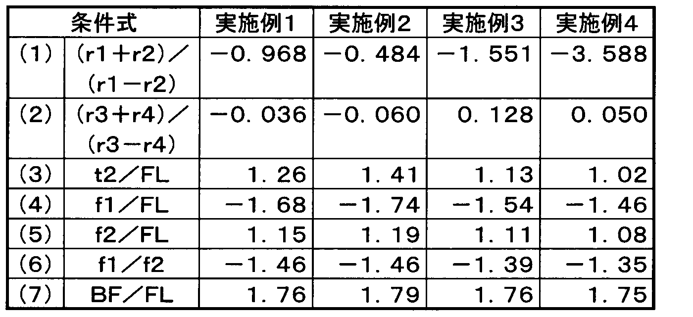
- the interval t2 (mm) is shown, and Table 3 shows the values corresponding to the conditional expressions of the respective examples (all are values at a wavelength of 3.3 ⁇ m).
- the back focus BF in Table 2 expresses the distance from the lens final surface to the paraxial image plane by the air conversion length (the bandpass filter BPF converts it to the air conversion length), and the lens total length TT is The back focus BF is added to the distance from the forefront lens (the object side surface of the first lens L1) to the final lens surface.
- Examples 1 to 4 EX 1 to 4
- (A) is a spherical aberration diagram
- (B) is an astigmatism diagram
- C) is a distortion diagram.
- the spherical aberration diagram shows the spherical aberration amount at the design wavelength (evaluation wavelength) of 3.3 ⁇ m indicated by the solid line, the spherical aberration amount at the wavelength of 3.1 ⁇ m indicated by the alternate long and short dash line, and the spherical aberration amount at the wavelength of 3.5 ⁇ m indicated by the broken line, respectively.
- the vertical axis represents the F number.
- the broken line T is the tangential image plane at the design wavelength of 3.3 ⁇ m
- the solid line S is the sagittal image plane at the design wavelength of 3.3 ⁇ m
- the vertical axis represents the half angle of view ⁇ (°).
- the horizontal axis represents the distortion (%) at the design wavelength of 3.3 ⁇ m
- the vertical axis represents the half angle of view ⁇ (°).
- Example 1 Unit mm Surface data Surface number R d N3.3 ⁇ Effective radius 1 (OB) ⁇ ⁇ - 2 * -83.476 5.000 3.433 234 (L1) 14.2 3 5174.121 25.418 14.9 4 * 105.238 10.000 3.433 234 (L2) 26.8 5 -113.160 13.400 27 6 (ST) ⁇ 1.700 12.7 7 ⁇ 1.200 4.036 103 (BPF) 12.2 8 ⁇ 20.003 12.1 9 (IM) ⁇ 0.000 6.0
- Example 2 Unit mm Surface data Surface number R d N3.3 ⁇ Effective radius 1 (OB) ⁇ ⁇ - 2 * -143.837 4.000 4.036 103 (L1) 14.2 3 413.819 28.282 14.6 4 * 106.160 10.000 3.433 234 (L2) 26.3 5 -119.674 12.000 26 6 (ST) ⁇ 1.700 13.8 7 ⁇ 1.200 4.036 103 (BPF) 13.3 8 ⁇ 22.000 13.2 9 (IM) ⁇ 0.000 6.0
- Example 3 Unit mm Surface data Surface number R d N3.3 ⁇ Effective radius 1 (OB) ⁇ ⁇ - 2 * -58.196 3.000 3.433 234 (L1) 12.1 3 -269.298 22.620 12.5 4 * 119.412 10.000 3.433 234 (L2) 19.0 5 -92.346 15.500 19 6 (ST) ⁇ 1.700 7.0 7 ⁇ 1.200 4.036 103 (BPF) 6.9 8 ⁇ 17.700 6.9 9 (IM) ⁇ 0.000 6.5
- Example 4 Unit mm Surface data Surface number R d N3.3 ⁇ Effective radius 1 (OB) ⁇ ⁇ - 2 * -35.424 3.000 4.036 103 (L1) 11.7 3 -62.798 20.412 12.6 4 * 106.598 10.000 3.433 234 (L2) 18.7 5 -96.492 14.800 8.0 6 ⁇ 1.700 4.036 103 (BPF) 7.2 7 (ST) ⁇ 19.700 7.0 8 (IM) ⁇ 0.000 6.5
- Cooling unit LN Infrared optical system L1 First lens L2 Second lens ST Aperture (cold aperture) CS Cold shield WI Window BPF Bandpass filter SR Imaging sensor (cooling sensor) SS Photosensitive surface (imaging surface) IM image plane (optical image) AX Optical axis 1 Signal processing unit 2 Control unit 3 Memory 4 Operation unit 5 Display unit
Landscapes
- Physics & Mathematics (AREA)
- General Physics & Mathematics (AREA)
- Optics & Photonics (AREA)
- Health & Medical Sciences (AREA)
- Toxicology (AREA)
- Lenses (AREA)
- Blocking Light For Cameras (AREA)
- Camera Bodies And Camera Details Or Accessories (AREA)
- Lens Barrels (AREA)
Abstract
波長3~5μm帯を使用する赤外線用光学系は、物体側から像側へかけて、負のパワーを有し両凹形状又は物体側に凹のメニスカス形状を有する第1レンズと、正のパワーを有し両凸形状を有する第2レンズと、絞りとからなり、第2レンズと像面との間にバンドパスフィルターを有する。第1レンズと第2レンズがいずれも非球面を少なくとも1面有し、バンドパスフィルターは波長3.1~3.5μmの光のみを透過させる特性を有する。赤外線用光学系は、条件式:-3.6<(r1+r2)/(r1-r2)<-0.4(r1,r2:第1レンズの物体側面,像側面の曲率半径),-0.2<(r3+r4)/(r3-r4)<0.2(r3,r4:第2レンズの物体側面,像側面の曲率半径)を満足する。
Description
本発明は、赤外線用光学系,撮像光学装置及びデジタル機器に関するものである。例えば、波長3~5μm帯の赤外線領域でガス検知用の撮影光学系として冷却センサーに使用される赤外線用光学系と、赤外線用光学系により得られた赤外線映像を冷却センサー等の撮像センサーで取り込む撮像光学装置と、赤外線用光学系を搭載した画像入力機能付きデジタル機器と、に関するものである。
メタン,エタン,プロパン,ブタン等の炭化水素系の物質に特有の吸収波長帯は、波長3~5μm帯のあたりに集まっていることが知られている。また、これらの炭化水素系の物質は、常温で気体でありかつ引火の危険性があるため、取り扱いには注意を要する。そのため近年では、これらの吸収によるコントラスト差を赤外線カメラで撮影することにより、可視光では捕らえられないガス漏れ等を検知することが行われつつある。
波長3~5μm帯は、プランクの法則から容易に分かるとおり、太陽から放射される光では、可視光より大幅に光量が少ない領域である。また、地面等の周辺環境から放射される光では、8~14μm帯のいわゆる遠赤外線より大幅に光量が少ない領域でもある。そのため、遠赤外線領域で一般的な非冷却センサーを使用して撮影することは困難であり、結果として、冷却センサーを用いてわずかな光を検知することが必要になる。冷却センサーを使用すれば、上記炭化水素系の吸収が少量であっても感度良く検出することができる。そこで、冷却センサーに搭載可能でS/N比及び光学性能の良好な赤外線用光学系が望まれている。
赤外線用光学系としては、例えば特許文献1,2に記載のものが挙げられる。特許文献1に記載の赤外線用光学系は、物体側に凹のメニスカス形状を有する第1レンズと、両凸形状を有する第2レンズと、のレンズ2枚で構成されている。絞りは第2レンズの物体側面に配置されており、第1レンズの像側面と第2レンズの物体側面が非球面で構成されている。また特許文献2には、両凹の第1レンズと両凸の第2レンズとのレンズ2枚で構成された赤外線用光学系が記載されている。絞りは第2レンズの物体側面近傍に配置されており、第1レンズは物体側面の曲率が像側面の曲率よりも弱く、ほぼ平面に近い形状になっている。
特許文献1,2に記載の赤外線用光学系では、絞りを第1レンズと第2レンズとの間に配置することにより、2枚という少ないレンズ枚数で光学性能を確保しようとしている。このため、これを冷却センサーに搭載する場合には、絞りとは別にコールドシールドを配置して、絞りと冷却センサーとの間から入射する不要光をカットする必要がある。しかしその場合、瞳を完全に合わせることができず、不要光をすべてカットすることが困難になるという課題がある。さらに特許文献2に記載の赤外線用光学系では、第1レンズの物体側面の曲率が像側面の曲率と比較して緩く、また、第2レンズの像側面の曲率が物体側面の曲率と比較して緩いため、絞りを第2レンズとセンサーとの間に配置しようとすると、収差が補正しにくくなるという課題もある。
本発明はこのような状況に鑑みてなされたものであって、その目的は、冷却センサーに搭載可能であって、2枚という少ないレンズ枚数で透過率が高くS/N比及び光学性能の良好な赤外線用光学系、それを備えた撮像光学装置及びデジタル機器を提供することにある。
上記目的を達成するために、第1の発明の赤外線用光学系は、波長3~5μm帯を使用する赤外線用撮影光学系であって、
物体側から像側へかけて、負のパワーを有し両凹形状又は物体側に凹のメニスカス形状を有する第1レンズと、正のパワーを有し両凸形状を有する第2レンズと、絞りとからなり、かつ、前記第2レンズと像面との間にバンドパスフィルターを有し、
前記第1レンズと第2レンズがいずれも非球面を少なくとも1面有し、
前記バンドパスフィルターが波長3.1~3.5μmの光のみを透過させる特性を有し、
以下の条件式(1)及び(2)を満足することを特徴とする。
-3.6<(r1+r2)/(r1-r2)<-0.4 …(1)
-0.2<(r3+r4)/(r3-r4)<0.2 …(2)
ただし、
r1:第1レンズの物体側面の曲率半径、
r2:第1レンズの像側面の曲率半径、
r3:第2レンズの物体側面の曲率半径、
r4:第2レンズの像側面の曲率半径、
である。
第2の発明の赤外線用光学系は、上記第1の発明において、以下の条件式(3)を満足することを特徴とする。
0.9<t2/FL<1.4 …(3)
ただし、
t2:第1レンズの像側面から第2レンズの物体側面までの光軸上での距離、
FL:全系の焦点距離、
である。
0.9<t2/FL<1.4 …(3)
ただし、
t2:第1レンズの像側面から第2レンズの物体側面までの光軸上での距離、
FL:全系の焦点距離、
である。
第3の発明の赤外線用光学系は、上記第1又は第2の発明において、以下の条件式(4)を満足することを特徴とする。
-2.2<f1/FL<-1.4 …(4)
ただし、
f1:第1レンズの焦点距離、
FL:全系の焦点距離、
である。
-2.2<f1/FL<-1.4 …(4)
ただし、
f1:第1レンズの焦点距離、
FL:全系の焦点距離、
である。
第4の発明の赤外線用光学系は、上記第1~第3のいずれか1つの発明において、以下の条件式(5)を満足することを特徴とする。
1.0<f2/FL<1.2 …(5)
ただし、
f2:第2レンズの焦点距離、
FL:全系の焦点距離、
である。
1.0<f2/FL<1.2 …(5)
ただし、
f2:第2レンズの焦点距離、
FL:全系の焦点距離、
である。
第5の発明の赤外線用光学系は、上記第1~第4のいずれか1つの発明において、前記第1,第2レンズがゲルマニウム又はシリコンで構成されていることを特徴とする。
第6の発明の赤外線用光学系は、上記第1~第5のいずれか1つの発明において、以下の条件式(6)を満足することを特徴とする。
-1.9<f1/f2<-1.2 …(6)
ただし、
f1:第1レンズの焦点距離、
f2:第2レンズの焦点距離、
である。
-1.9<f1/f2<-1.2 …(6)
ただし、
f1:第1レンズの焦点距離、
f2:第2レンズの焦点距離、
である。
第7の発明の赤外線用光学系は、上記第1~第6のいずれか1つの発明において、以下の条件式(7)を満足することを特徴とする。
1.5<BF/FL<1.8 …(7)
ただし、
BF:第2レンズの像側面から像面までの空気換算長、
FL:全系の焦点距離、
である。
1.5<BF/FL<1.8 …(7)
ただし、
BF:第2レンズの像側面から像面までの空気換算長、
FL:全系の焦点距離、
である。
第8の発明の赤外線用光学系は、上記第1~第7のいずれか1つの発明において、前記第1,第2レンズのいずれの面にも、表面レリーフ状の回折面又はフレネル面を有しないことを特徴とする。
第9の発明の赤外線用光学系は、上記第1~第8のいずれか1つの発明において、前記絞りがコールドシールドの一部からなるコールドアパーチャーであることを特徴とする。
第10の発明の撮像光学装置は、上記第1~第9のいずれか1つの発明に係る赤外線用光学系と、撮像面上に形成された赤外線光学像を電気的な信号に変換する撮像センサーと、を備え、前記撮像センサーの撮像面上に被写体の赤外線光学像が形成されるように前記赤外線用光学系が設けられていることを特徴とする。
第11の発明のデジタル機器は、上記第10の発明に係る撮像光学装置を備えることにより、被写体の静止画撮影,動画撮影のうちの少なくとも一方の機能が付加されたことを特徴とする。
第12の発明の赤外線用カメラシステムは、上記第1~第9のいずれか1つの発明に係る赤外線用光学系を備えたことを特徴とする。
本発明によれば、冷却センサーに搭載可能であって、2枚という少ないレンズ枚数で透過率が高くS/N比及び光学性能の良好な赤外線用光学系及び撮像光学装置を実現することができる。そして、本発明に係る赤外線用光学系又は撮像光学装置を、ガス検知装置,カメラシステム(例えば、監視カメラ,航空機カメラ)等のデジタル機器に用いることによって、デジタル機器に対し高性能の赤外線画像入力機能を安価に付加することが可能となる。
以下、本発明の実施の形態に係る赤外線用光学系,撮像光学装置,デジタル機器等を説明する。本発明の実施の形態に係る赤外線用光学系は、波長3~5μm帯を使用する赤外線用撮影光学系であって、物体側から像側へかけて、負のパワーを有し両凹形状又は物体側に凹のメニスカス形状を有する第1レンズと、正のパワーを有し両凸形状を有する第2レンズと、絞りとからなり(パワー:焦点距離の逆数で定義される量)、かつ、前記第2レンズと像面との間にバンドパスフィルターを有している。また、前記第1レンズと第2レンズがいずれも非球面を少なくとも1面有し、前記バンドパスフィルターが波長3.1~3.5μmの光のみを透過させる特性を有し、以下の条件式(1)及び(2)を満足することを特徴としている。
-3.6<(r1+r2)/(r1-r2)<-0.4 …(1)
-0.2<(r3+r4)/(r3-r4)<0.2 …(2)
ただし、
r1:第1レンズの物体側面の曲率半径、
r2:第1レンズの像側面の曲率半径、
r3:第2レンズの物体側面の曲率半径、
r4:第2レンズの像側面の曲率半径、
である。
-3.6<(r1+r2)/(r1-r2)<-0.4 …(1)
-0.2<(r3+r4)/(r3-r4)<0.2 …(2)
ただし、
r1:第1レンズの物体側面の曲率半径、
r2:第1レンズの像側面の曲率半径、
r3:第2レンズの物体側面の曲率半径、
r4:第2レンズの像側面の曲率半径、
である。
波長3~5μm帯の赤外線は、プランクの法則から容易に分かるとおり、太陽から放射される光では可視光よりも大幅に少なく、また地面等の周辺環境から放射される光では波長8~14μm帯のいわゆる遠赤外線よりも大幅に少ない。そのため、可視光や遠赤外線の領域での撮影に用いられる、いわゆる非冷却センサーを使用して撮影することが困難であり、冷却センサーを用いてわずかな光を検知することが必要になる。その冷却センサーの具体例としては、アンチモン化インジウム(InSb),プラチナシリコン(PtSi),テルル化カドミウム水銀(HgCdTe)等を素子素材とする、いわゆる量子型センサーが挙げられる。
赤外線用の撮像センサーは、赤外光(放射熱)を受光するとそれ自身が熱を持ち、それがノイズの原因となる。冷却センサーは、センサー自体を-200℃程度の極低温まで冷却することでこの現象を抑えている。しかし、冷却センサーはわずかな放射光も検知するため、絞りやレンズの保持部材等から放射される光も無視することができない。それらがセンサーに入射することは大きなノイズ源となり、画質のS/N比が大きく悪化することになる。これを防ぐため、絞りやレンズの保持部材等も同様に極低温に冷やす必要がある。そこで、レンズ系と撮像センサーとの間にコールドシールドを配置することが求められている。
図9に、コールドシールドの概略構成例を示す。コールドシールドCSは真空容器からなっており、コールドシールドCSの一部で絞りSTが構成されている。絞りSTとバンドパスフィルターBPFと冷却センサーSRは、赤外線を透過するウィンドウWIで密閉されたコールドシールドCS内にセットされて冷却される。第2レンズL2と像面IMとの間に絞りSTを配置し、かつ、その絞りSTを冷却して、いわゆるコールドアパーチャーとすることにより、正規光以外のセンサーSRへの入射光をカットすることができる。つまり、絞りSTからの放射光の発生を抑えるとともに、レンズ保持部材からの放射光を遮断することが可能となる。図10に、レンズ保持部材である鏡胴BLからの赤外光を絞りSTでカットする様子を示す。
前述したように第1レンズと第2レンズで負正のパワー配置にすると、いわゆるレトロフォーカスとなり、焦点距離よりも長いバックフォーカスを確保することができる。その結果、第2レンズと像面との間に絞り(コールドシールド)を配置することができるため、上述したように、絞りSTからの放射光の発生を抑えるとともに、レンズ保持部材からの放射光を遮断することが可能となる(図10)。また、2枚という少ないレンズ枚数からなる構成には、レンズ面での光の入射・射出の回数が減るため、光量の損失を最小限に抑える効果がある。その結果、光学系としては比較的高い透過率を確保することができ、面間反射の発生を抑えてS/N比の低下を防止することができる。さらに、第1レンズが両凹形状又は物体側に凹のメニスカス形状を有することによって、2枚という少ない枚数のもとで球面収差を良好に補正する効果が得られる。
絞りを第2レンズと像面との間に配置すると、軸上光と周辺光の通過位置が似通ってしまうが、第1レンズと第2レンズにそれぞれ非球面を少なくとも1面用いることで収差補正は容易になる。例えば、第1レンズと第2レンズとの間に絞りを配置した場合、軸上光と周辺光の通過位置が異なるため、画面中心と画面周辺とで発生する異なる感度の収差の補正を個別に行うことが可能となり、その結果、収差補正が比較的容易になる。それに対し、絞りを第2レンズと像面との間に配置した構成では、上記のように軸上光と周辺光の通過位置が似通ってしまうため、上記個別の補正効果が薄くなってしまい収差補正が難しくなる。
そこで、第1レンズと第2レンズのそれぞれ少なくとも1面を非球面とすることにより、非点収差,球面収差,コマ収差等を軸上のみならず周辺についても良好に補正することを可能としている。そして、良好な収差補正を行うためには、第1レンズは軸上から周辺に行くに従い基準曲率よりきつくなる(すなわち曲率半径が小さくなる)形状の非球面を有することが望ましく、第2レンズは軸上から周辺に行くに従い基準曲率より緩くなる(すなわち曲率半径が大きくなる)形状の非球面を有することが望ましい。
赤外線用光学系の使用波長帯は、遠赤外用としては8~14μm、中赤外用としては3~5μmが一般的である。それ以外の波長域、例えば5~8μm帯や2.5~3μm帯は大気中での水や二酸化炭素の吸収が多いのであまり一般的ではなく、また、波長3.6~5μmの光が撮像センサーに入るとS/N比が低下して検出感度が低下してしまうおそれがある。そこで、波長3.1~3.5μmの光のみを透過させる特性のバンドパスフィルターを、絞りと同様、第2レンズと像面との間に配置している。
第2レンズと像面との間にバンドパスフィルターを有する構成では、バンドパスフィルターをコールドアパーチャー近傍に配置することができるため、バンドパスフィルターをコールドアパーチャーと同様に冷却することがメカ構成上可能となる。そして、バンドパスフィルターを冷却することで、バンドパスフィルターからの放射光を最小限に低減する効果が得られる。したがって、コールドアパーチャーの像側にバンドパスフィルターを配置してもよく、コールドアパーチャーの物体側にバンドパスフィルターを配置してもよい。
波長3.1~3.5μmの間には、メタン,プロパン等さまざまな炭化水素系の物質の吸収波長帯が存在している。それらの物質を感度良く検知するには、この程度の波長幅で透過させることが望ましい。広すぎては波長幅に対して吸収帯の割合が狭くなり、狭すぎると信号の絶対量が減ってしまい暗くなりすぎてしまう。
前記バンドパスフィルターは、波長3.2~3.4μmの光のみを透過させる特性を有することが更に望ましい。この透過特性を有するバンドパスフィルターであれば、上記観点に基づく効果をより一層大きくすることができる。
バンドパスフィルターで波長帯を制限する場合、レンズ系が明るくなるようにFナンバーを設定することが、光量を確保するために望ましい。つまり、3.1~3.5μmや更には3.2~3.4μmの波長帯では、光量が不足する可能性があるので、レンズ系には通常より明るいFナンバーが要求される。したがって、波長3~5μm帯を使用する赤外線用光学系としては、Fナンバーが1.5以下に明るいこと(Fno≦1.5)が望ましい。なお、波長3~5μm帯の通常の赤外線用光学系では、通常4程度のFナンバーである。
第1レンズと第2レンズにそれぞれ非球面を少なくとも1面付加しているため、軸上と周辺での局所的な曲率を変えることが可能となり、それによって軸上と軸外で個別に収差を補正することが可能となるが、F値の明るいレンズ系を達成しつつ非点収差と球面収差をバランス良く補正するためには、それに加えて条件式(1),(2)の範囲を満足することがさらに望ましい。
条件式(1),(2)は、第1,第2レンズのシェイプファクターを規定している。条件式(1)及び(2)を満足することにより、歪曲収差と球面収差と非点収差とをバランス良く補正することができる。条件式(1)の上限内であれば、非点収差と歪曲とのバランスを取ることが容易になり、条件式(1)の下限内であれば、球面収差と歪曲とのバランスを取ることが容易になる。条件式(2)の上限内であれば、球面収差と歪曲とのバランスを取ることが容易になり、条件式(2)の下限内であれば、非点収差と歪曲とのバランスを取ることが容易になる。したがって、条件式(1),(2)の範囲であることが望ましい。また、電気的に歪曲補正や周辺照度補正を行うことが更に望ましい。
上記特徴的構成によると、冷却センサーに搭載可能であって、2枚という少ないレンズ枚数で透過率が高くS/N比及び光学性能の良好な赤外線用光学系及び撮像光学装置を実現することができる。そして、その赤外線用光学系又は撮像光学装置を、ガス検知装置,カメラシステム(例えば、監視カメラ,航空機カメラ)等のデジタル機器に用いることによって、デジタル機器に対し高性能の赤外線画像入力機能を安価に付加することが可能となり、デジタル機器の低コスト化,高性能化,高機能化等に寄与することができる。冷却センサー対応の赤外線用光学系を、上記のようにS/N比と光学性能を良好に両立させながらレンズ2枚でも実現可能とし、こういった効果をバランス良く得るとともに、更に高い光学性能,軽量・小型化等を達成するうえで望ましい条件設定等を以下に説明する。
以下の条件式(3)を満足することが望ましい。
0.9<t2/FL<1.4 …(3)
ただし、
t2:第1レンズの像側面から第2レンズの物体側面までの光軸上での距離、
FL:全系の焦点距離、
である。
0.9<t2/FL<1.4 …(3)
ただし、
t2:第1レンズの像側面から第2レンズの物体側面までの光軸上での距離、
FL:全系の焦点距離、
である。
条件式(3)は、第1,第2レンズ間隔に関する好ましい条件範囲を規定している。条件式(3)の下限を下回ると、第1レンズと第2レンズとの間隔が狭くなり、軸上光束と軸外光束の通過位置をずらすことが難しくなるため、軸上の収差と軸外の収差を個別に補正することが難しい傾向となる。また、条件式(3)の上限を上回ると、光学系の全長が増大傾向となり、ひいてはレンズ径の増大により加工が難しくなるおそれがある。したがって、この条件式(3)の範囲内が望ましく、条件式(3)を満たすことにより、全長の増大を抑えながら軸上と軸外の収差をバランス良く補正してF値の明るいレンズを達成することができ、小型化と高性能化を効果的に両立させることが可能となる。
以下の条件式(4)を満足することが望ましい。
-2.2<f1/FL<-1.4 …(4)
ただし、
f1:第1レンズの焦点距離、
FL:全系の焦点距離、
である。
-2.2<f1/FL<-1.4 …(4)
ただし、
f1:第1レンズの焦点距離、
FL:全系の焦点距離、
である。
条件式(4)は、非球面を少なくとも1面有する第1レンズのパワーに関する好ましい条件範囲を規定している。条件式(4)の下限を下回ると、第1レンズのパワーが弱くなりすぎて、非球面を配置しても顕著な収差補正効果を得ることが難しい傾向となる。条件式(4)の上限を上回ると、第1レンズのパワーが強くなりすぎて、レンズ系とセンサーと間に絞りを配置しつつ収差を良好に補正することが難しい傾向となる。したがって、この条件式(4)の範囲内が望ましく、条件式(4)を満たすことにより、第1レンズに配置した非球面の効果を最大限に発揮することが可能になる。
以下の条件式(5)を満足することが望ましい。
1.0<f2/FL<1.2 …(5)
ただし、
f2:第2レンズの焦点距離、
FL:全系の焦点距離、
である。
1.0<f2/FL<1.2 …(5)
ただし、
f2:第2レンズの焦点距離、
FL:全系の焦点距離、
である。
条件式(5)は、非球面を少なくとも1面有する第2レンズのパワーに関する好ましい条件範囲を規定している。条件式(5)の下限を下回ると、第2レンズのパワーが強くなりすぎて非点収差が増大し、それを第1レンズのみで補正することが難しい傾向となる。条件式(5)の上限を上回ると、第2レンズのパワーが弱くなることで、全長を抑えながら球面収差や非点収差を良好に抑えることが難しい傾向となる。また、全長の増大や第1レンズの有効径の増大を招く傾向となる。したがって、この条件式(5)の範囲内が望ましく、条件式(5)を満たすことにより、第2レンズに配置した非球面の効果を最大限に発揮させて、諸収差(非点収差,球面収差等)の良好な補正と小型化とをバランス良く両立させることが可能になる。
前記第1,第2レンズがゲルマニウム(Ge)又はシリコン(Si)で構成されていることが望ましく、第1,第2レンズともシリコンであることが更に望ましい。シリコンやゲルマニウムのような高い屈折率の材料を使用すると、レンズに対する入射角・反射角を小さくすることができ、各レンズ面での収差発生量を抑える効果が得られる。各レンズ面での収差発生量が多いと、その収差補正のためにレンズを多数配置する必要があり、その結果、面間反射が増えてS/N比が悪化することになる。そこで、波長3~5μm帯で透過率及び屈折率が高い代表的な硝材と言えば、ゲルマニウムやシリコンということになる。
以下の条件式(6)を満足することが望ましい。
-1.9<f1/f2<-1.2 …(6)
ただし、
f1:第1レンズの焦点距離、
f2:第2レンズの焦点距離、
である。
-1.9<f1/f2<-1.2 …(6)
ただし、
f1:第1レンズの焦点距離、
f2:第2レンズの焦点距離、
である。
条件式(6)は、第1レンズと第2レンズとの好ましいパワー比を規定している。条件式(6)の上限を上回ると、非点収差と歪曲収差とをバランス良く補正することが難しい傾向となる。条件式(6)の下限を下回ると、非点収差と球面収差とをバランス良く補正することが難しい傾向となる。また、条件式(6)の下限を下回ると、第2レンズのパワーと比較して第1レンズのパワーが弱くなるので、レトロフォーカス度合いが薄れ、全系の焦点距離を保持しようとすれば全長の増大を招くおそれがある。したがって、この条件式(6)の範囲内が望ましく、条件式(6)を満たすことにより、全長の増大を抑えながら球面収差,非点収差及び歪曲収差をバランス良く補正しつつF値の明るいレンズを達成することが可能になる。
以下の条件式(7)を満足することが望ましい。
1.5<BF/FL<1.8 …(7)
ただし、
BF:第2レンズの像側面から像面までの空気換算長、
FL:全系の焦点距離、
である。
1.5<BF/FL<1.8 …(7)
ただし、
BF:第2レンズの像側面から像面までの空気換算長、
FL:全系の焦点距離、
である。
条件式(7)は、バックフォーカスに関する好ましい条件範囲を規定している。条件式(7)の上限を下回ると、レトロフォーカスを構成する各群のパワーを抑えることができ、その結果、各群での収差発生を効果的に抑制することができる。条件式(7)の下限を上回ると、レンズ-センサー間にコールドシールドを配置する十分なスペースを効果的に確保することができる。また、バックフォーカスが条件式(7)の範囲内であると、レンズ-センサー間にコールドシールドを配置するスペースの確保が容易になるとともに、逆にバックフォーカスを作為的に伸ばすことに起因する収差の悪化も比較的少なくて済む。したがって、この条件式(7)の範囲内が望ましく、条件式(7)を満たすことにより、レンズとセンサーと間にコールドシールドを配置しつつ収差を良好に補正することが可能となる。
前記第1,第2レンズのいずれの面にも、表面レリーフ状の回折面又はフレネル面を有しないことが望ましい。波長8~14μm帯のいわゆる遠赤外線を使用する光学系では、回折面を使用して色収差を補正することが行われている。しかし、回折面では高次項による回折光が発生してゴースト光やフレア成分になりやすい。また、回折面の特性上、どうしても立ち壁が発生するが、この立ち壁での反射・屈折は上記と同様のゴースト光やフレア成分が発生する原因となる。冷却センサーは感度が高いので、これら不要光は大きなノイズ要因となってS/N比を低下させるおそれがある。これは表面レリーフ状の回折面に限らず、フレネル面でも同様である。
前記絞りがコールドシールドの一部からなるコールドアパーチャーであることが望ましい。絞りを冷却することで(いわゆるコールドアパーチャーとすることで)、例えば、保持部材からの放射光を遮断することができる。また、絞り自体からの放射光の発生を抑える効果もある。
以上説明した赤外線用光学系は、赤外線画像入力機能付きデジタル機器(例えば、赤外線カメラ付きガス漏れ検知システム)用の撮像光学系としての使用に適しており、これを撮像用の冷却センサー等と組み合わせることにより、被写体の赤外線映像を光学的に取り込んで電気的な信号として出力する赤外線用撮像光学装置を構成することができる。撮像光学装置は、被写体の静止画撮影や動画撮影に用いられるカメラの主たる構成要素を成す光学装置であり、例えば、物体(すなわち被写体)側から順に、物体の赤外線光学像を形成する赤外線用光学系と、その赤外線用光学系により形成された赤外線光学像を電気的な信号に変換する撮像センサー(例えば、冷却センサーに相当する。)と、を備えることにより構成される。そして、撮像センサーの受光面(すなわち撮像面)上に被写体の赤外線光学像が形成されるように、前述した特徴的構成を有する赤外線用光学系が配置されることにより、小型・低コストで高い性能を有する撮像光学装置やそれを備えたデジタル機器を実現することができる。
赤外線画像入力機能付きデジタル機器の例としては、赤外線カメラ,監視カメラ,航空機カメラ,船舶用カメラ,火災検知用カメラ等が挙げられ、また、ガス検知装置,ガス漏れ検知システム,暗視装置,サーモグラフィー,インフラ監視用システム(高圧電線・工場内・プラント内での異常熱源の監視、構造物の劣化監視等)等が挙げられる。
上記の例から分かるように、赤外線用の撮像光学装置を用いることにより赤外線カメラシステムを構成することができるだけでなく、その撮像光学装置を各種機器に搭載することにより赤外線カメラ機能,暗視機能,温度測定機能等を付加することが可能である。例えば、炭化水素系の物質(メタン,エタン,プロパン,ブタン等)に特有の吸収波長帯の赤外線吸収によるコントラスト差を撮影する機能を、赤外線画像入力機能として備えた赤外線カメラ付きガス検知装置を構成することにより、可視光では捕らえられないガス漏れ等を検知することが可能である。
赤外線画像入力機能付きデジタル機器の一例として、図11にデジタル機器DUの概略構成例を模式的断面で示す。図11に示すデジタル機器DUに搭載されている撮像光学装置LUは、物体(すなわち被写体)側から順に、物体の赤外線光学像(像面)IMを形成する赤外線用光学系LN(AX:光軸)と、赤外線用光学系LNにより受光面(撮像面)SS上に形成された光学像IMを電気的な信号に変換する撮像センサー(冷却センサー)SRと、を備えている。赤外線用光学系LNは、2枚の単レンズと、コールドアパーチャーと、バンドパスフィルターと、からなる2枚構成の単焦点撮影光学系であり、撮像センサーSRの光電変換部である受光面SS上に赤外線からなる光学像IMを形成する構成になっている。
赤外線用光学系LNに内蔵のバンドパスフィルター以外の平行平面板を、必要に応じて配置してもよい。そのような平行平面板として、例えば、冷却部CUを構成するコールドシールドCS(図9,図10)を密閉するために、コールドアパーチャー近傍にウィンドウWI(図9,図10)を配置してもよく、耐傷・耐薬品等を考慮して、最も物体側に位置する第1レンズの外側に、波長3~5μm帯の赤外線を通過するカバー部材や窓材を配置してもよい。また、撮像光学装置LUで画像入力機能付きデジタル機器DUを構成する場合、通常そのボディ内部に撮像光学装置LUを配置することになるが、カメラ機能を実現する際には必要に応じた形態を採用することが可能である。例えば、ユニット化した撮像光学装置LUをデジタル機器DUの本体に対して着脱可能又は回動可能に構成することが可能である。
デジタル機器DUは、撮像光学装置LUの他に、信号処理部1,制御部2,メモリー3,操作部4,表示部5等を備えている。撮像センサーSRで生成した信号は、信号処理部1で所定のデジタル画像処理や画像圧縮処理等が必要に応じて施され、デジタル映像信号としてメモリー3(半導体メモリー,光ディスク等)に記録されたり、場合によってはケーブルを介したり赤外線信号等に変換されたりして他の機器に伝送される(例えば携帯電話の通信機能)。制御部2はマイクロコンピューターからなっており、撮影機能(静止画撮影機能,動画撮影機能等),画像再生機能等の機能の制御;フォーカシング等のためのレンズ移動機構の制御等を集中的に行う。例えば、被写体の静止画撮影,動画撮影のうちの少なくとも一方を行うように、制御部2により撮像光学装置LUに対する制御が行われる。表示部5は液晶モニター等のディスプレイを含む部分であり、撮像センサーSRによって変換された画像信号あるいはメモリー3に記録されている画像情報を用いて画像表示を行う。操作部4は、操作ボタン(例えばレリーズボタン),操作ダイヤル(例えば撮影モードダイヤル)等の操作部材を含む部分であり、操作者が操作入力した情報を制御部2に伝達する。
図1,図3,図5,図7に、無限遠合焦状態にある赤外線用光学系LNの第1~第4の実施の形態を光学断面でそれぞれ示す。第1~第4の実施の形態のいずれについても、赤外線用光学系LNは、物体側から像側へかけて、負のパワーを有する第1レンズL1と、正のパワーを有する第2レンズL2と、絞り(コールドアパーチャー)STと、が配置されており(パワーについてはすべて近軸での値とする。)、第2レンズL2と像面IMとの間には、絞りSTの他にバンドパスフィルターBPFが配置されている。バンドパスフィルターBPFは、絞りSTの像面IM側又は物体側において絞りSTの近傍に配置されている。
第1,第2の実施の形態において、第1レンズL1は両凹形状を有する負レンズであり、第3,第4の実施の形態において、第1レンズL1は物体側に凹のメニスカス形状を有する負レンズである。第1~第4の実施の形態のいずれにおいても、第2レンズL2は両凸形状を有する正レンズであり、第1レンズL1と第2レンズL2の各物体側面は非球面で構成されている。第1,第3の実施の形態において第1レンズL1はシリコンで構成されており、第2,第4の実施の形態において第1レンズL1はゲルマニウムで構成されており、第1~第4の実施の形態において第2レンズL2はシリコンで構成されている。
第1~第4の実施の形態のいずれにおいても、コールドアパーチャーST近傍には、前述した冷却部CU(図11)を密閉するためのウィンドウWIが配置されることがあるが、冷却効果が十分であれば省略してもよい。また、最も物体側に位置する第1レンズL1の外側には、耐傷・耐薬品等を考慮して該当する赤外線を通過するカバー部材又は窓材を配置してもよい。
以下、本発明を実施した赤外線用光学系の構成等を、実施例のコンストラクションデータ等を挙げて更に具体的に説明する。ここで挙げる実施例1~4(EX1~4)は、前述した第1~第4の実施の形態にそれぞれ対応する数値実施例であり、第1~第4の実施の形態を表すレンズ構成図(図1,図3,図5,図7)は、対応する実施例1~4のレンズ断面形状,レンズ配置等をそれぞれ示している。
各実施例のコンストラクションデータでは、面データとして、左側の欄から順に、面番号(OB:物面,ST:絞り面,IM:像面),近軸における曲率半径R(mm),軸上面間隔d(mm),波長3.3μmに対する屈折率N3.3,及び波長3~5μmに対する分散値νを示す。分散値νは分散の性質を表し、ν=(N4-1)/(N3-N5)で定義される(ただし、N3:波長3μmに対する屈折率,N4:波長4μmに対する屈折率,N5:波長5μmに対する屈折率である。)。表1に、シリコン(Si)とゲルマニウム(Ge)の屈折率N5,N4,N3.3,N3及び分散値νを示す。
面番号に*が付された面は非球面であり、その面形状は面頂点を原点とするローカルな直交座標系(x,y,z)を用いた以下の式(AS)で定義される。非球面データとして、非球面係数等を示す。なお、各実施例の非球面データにおいて表記の無い項の係数は0であり、すべてのデータに関してE-n=×10-nである。
z=(C・h2)/[1+√{1-(1+K)・C2・h2}]+Σ(Ai・hi) …(AS)
ただし、
h:z軸(光軸AX)に対して垂直な方向の高さ(h2=x2+y2)、
z:高さhの位置での光軸AX方向のサグ量(面頂点基準)、
C:面頂点での曲率(近軸曲率半径Rの逆数)、
K:円錐定数、
Ai:i次の非球面係数(Σはiについて4次から∞次の総和を表す。)、
である。
z=(C・h2)/[1+√{1-(1+K)・C2・h2}]+Σ(Ai・hi) …(AS)
ただし、
h:z軸(光軸AX)に対して垂直な方向の高さ(h2=x2+y2)、
z:高さhの位置での光軸AX方向のサグ量(面頂点基準)、
C:面頂点での曲率(近軸曲率半径Rの逆数)、
K:円錐定数、
Ai:i次の非球面係数(Σはiについて4次から∞次の総和を表す。)、
である。
表2に、各種データとして、全系の焦点距離FL(mm),Fナンバー(Fno),全画角2ω(°),レンズ全長TT(mm),バックフォーカスBF(mm),像高Y’(mm),第1レンズL1の焦点距離f1(mm),第2レンズL2の焦点距離f2(mm),第1レンズL1の物体側面の曲率半径r1(mm),第1レンズL1の像側面の曲率半径r2(mm),第2レンズL2の物体側面の曲率半径r3(mm),第2レンズL2の像側面の曲率半径r4(mm),及び第1レンズL1と第2レンズL2との間隔t2(mm)を示し、表3に各実施例の条件式対応値を示す(いずれも波長3.3μmでの値である。)。表2中のバックフォーカスBFは、レンズ最終面から近軸像面までの距離を空気換算長により表記しており(バンドパスフィルターBPFは空気換算長に変換している。)、レンズ全長TTは、レンズ最前面(第1レンズL1の物体側面)からレンズ最終面までの距離にバックフォーカスBFを加えたものである。
図2,図4,図6,図8は、実施例1~4(EX1~4)にそれぞれ対応する収差図であり、(A)は球面収差図、(B)は非点収差図、(C)は歪曲収差図である。球面収差図は、実線で示す設計波長(評価波長)3.3μmにおける球面収差量、一点鎖線で示す波長3.1μmにおける球面収差量、破線で示す波長3.5μmにおける球面収差量を、それぞれ近軸像面からの光軸AX方向のズレ量(mm)で表しており、縦軸はFナンバーを表している。非点収差図において、破線Tは設計波長3.3μmにおけるタンジェンシャル像面、実線Sは設計波長3.3μmにおけるサジタル像面を、近軸像面からの光軸AX方向のズレ量(mm)で表しており、縦軸は半画角ω(°)を表している。歪曲収差図において、横軸は設計波長3.3μmにおける歪曲(%)を表しており、縦軸は半画角ω(°)を表している。
実施例1
単位:mm
面データ
面番号 R d N3.3 ν 有効半径
1(OB) ∞ ∞ -
2* -83.476 5.000 3.433 234(L1) 14.2
3 5174.121 25.418 14.9
4* 105.238 10.000 3.433 234(L2) 26.8
5 -113.160 13.400 27
6(ST) ∞ 1.700 12.7
7 ∞ 1.200 4.036 103(BPF) 12.2
8 ∞ 20.003 12.1
9(IM) ∞ 0.000 6.0
単位:mm
面データ
面番号 R d N3.3 ν 有効半径
1(OB) ∞ ∞ -
2* -83.476 5.000 3.433 234(L1) 14.2
3 5174.121 25.418 14.9
4* 105.238 10.000 3.433 234(L2) 26.8
5 -113.160 13.400 27
6(ST) ∞ 1.700 12.7
7 ∞ 1.200 4.036 103(BPF) 12.2
8 ∞ 20.003 12.1
9(IM) ∞ 0.000 6.0
非球面データ
面番号 K A4 A6 A8 A10
2 11.55 -4.128E-06 -1.041E-09 -2.931E-11 4.833E-14
4 3.17 -2.003E-06 1.005E-10 4.855E-14 -3.662E-17
面番号 K A4 A6 A8 A10
2 11.55 -4.128E-06 -1.041E-09 -2.931E-11 4.833E-14
4 3.17 -2.003E-06 1.005E-10 4.855E-14 -3.662E-17
実施例2
単位:mm
面データ
面番号 R d N3.3 ν 有効半径
1(OB) ∞ ∞ -
2* -143.837 4.000 4.036 103(L1) 14.2
3 413.819 28.282 14.6
4* 106.160 10.000 3.433 234(L2) 26.3
5 -119.674 12.000 26
6(ST) ∞ 1.700 13.8
7 ∞ 1.200 4.036 103(BPF) 13.3
8 ∞ 22.000 13.2
9(IM) ∞ 0.000 6.0
単位:mm
面データ
面番号 R d N3.3 ν 有効半径
1(OB) ∞ ∞ -
2* -143.837 4.000 4.036 103(L1) 14.2
3 413.819 28.282 14.6
4* 106.160 10.000 3.433 234(L2) 26.3
5 -119.674 12.000 26
6(ST) ∞ 1.700 13.8
7 ∞ 1.200 4.036 103(BPF) 13.3
8 ∞ 22.000 13.2
9(IM) ∞ 0.000 6.0
非球面データ
面番号 K A4 A6 A8 A10
2 -8.49 -5.349E-06 -2.457E-09 -2.164E-11 2.921E-14
4 3.88 -1.937E-06 7.364E-11 -5.843E-15 -2.131E-17
面番号 K A4 A6 A8 A10
2 -8.49 -5.349E-06 -2.457E-09 -2.164E-11 2.921E-14
4 3.88 -1.937E-06 7.364E-11 -5.843E-15 -2.131E-17
実施例3
単位:mm
面データ
面番号 R d N3.3 ν 有効半径
1(OB) ∞ ∞ -
2* -58.196 3.000 3.433 234(L1) 12.1
3 -269.298 22.620 12.5
4* 119.412 10.000 3.433 234(L2) 19.0
5 -92.346 15.500 19
6(ST) ∞ 1.700 7.0
7 ∞ 1.200 4.036 103(BPF) 6.9
8 ∞ 17.700 6.9
9(IM) ∞ 0.000 6.5
単位:mm
面データ
面番号 R d N3.3 ν 有効半径
1(OB) ∞ ∞ -
2* -58.196 3.000 3.433 234(L1) 12.1
3 -269.298 22.620 12.5
4* 119.412 10.000 3.433 234(L2) 19.0
5 -92.346 15.500 19
6(ST) ∞ 1.700 7.0
7 ∞ 1.200 4.036 103(BPF) 6.9
8 ∞ 17.700 6.9
9(IM) ∞ 0.000 6.5
非球面データ
面番号 K A4 A6 A8 A10
2 9.01 -1.789E-06 -1.175E-10 -3.379E-12 6.887E-14
4 2.18 -2.112E-06 2.149E-10 7.382E-14 7.090E-17
面番号 K A4 A6 A8 A10
2 9.01 -1.789E-06 -1.175E-10 -3.379E-12 6.887E-14
4 2.18 -2.112E-06 2.149E-10 7.382E-14 7.090E-17
実施例4
単位:mm
面データ
面番号 R d N3.3 ν 有効半径
1(OB) ∞ ∞ -
2* -35.424 3.000 4.036 103(L1) 11.7
3 -62.798 20.412 12.6
4* 106.598 10.000 3.433 234(L2) 18.7
5 -96.492 14.800 8.0
6 ∞ 1.700 4.036 103(BPF) 7.2
7(ST) ∞ 19.700 7.0
8(IM) ∞ 0.000 6.5
単位:mm
面データ
面番号 R d N3.3 ν 有効半径
1(OB) ∞ ∞ -
2* -35.424 3.000 4.036 103(L1) 11.7
3 -62.798 20.412 12.6
4* 106.598 10.000 3.433 234(L2) 18.7
5 -96.492 14.800 8.0
6 ∞ 1.700 4.036 103(BPF) 7.2
7(ST) ∞ 19.700 7.0
8(IM) ∞ 0.000 6.5
非球面データ
面番号 K A4 A6 A8 A10
2 3.89 5.696E-06 2.488E-08 -4.791E-11 7.010E-13
4 0.50 -2.291E-06 4.069E-10 -3.439E-13 7.321E-16
面番号 K A4 A6 A8 A10
2 3.89 5.696E-06 2.488E-08 -4.791E-11 7.010E-13
4 0.50 -2.291E-06 4.069E-10 -3.439E-13 7.321E-16


DU デジタル機器
LU 撮像光学装置
CU 冷却部
LN 赤外線用光学系
L1 第1レンズ
L2 第2レンズ
ST 絞り(コールドアパーチャー)
CS コールドシールド
WI ウィンドウ
BPF バンドパスフィルター
SR 撮像センサー(冷却センサー)
SS 受光面(撮像面)
IM 像面(光学像)
AX 光軸
1 信号処理部
2 制御部
3 メモリー
4 操作部
5 表示部
LU 撮像光学装置
CU 冷却部
LN 赤外線用光学系
L1 第1レンズ
L2 第2レンズ
ST 絞り(コールドアパーチャー)
CS コールドシールド
WI ウィンドウ
BPF バンドパスフィルター
SR 撮像センサー(冷却センサー)
SS 受光面(撮像面)
IM 像面(光学像)
AX 光軸
1 信号処理部
2 制御部
3 メモリー
4 操作部
5 表示部
Claims (12)
- 波長3~5μm帯を使用する赤外線用撮影光学系であって、
物体側から像側へかけて、負のパワーを有し両凹形状又は物体側に凹のメニスカス形状を有する第1レンズと、正のパワーを有し両凸形状を有する第2レンズと、絞りとからなり、かつ、前記第2レンズと像面との間にバンドパスフィルターを有し、
前記第1レンズと第2レンズがいずれも非球面を少なくとも1面有し、
前記バンドパスフィルターが波長3.1~3.5μmの光のみを透過させる特性を有し、
以下の条件式(1)及び(2)を満足することを特徴とする赤外線用光学系;
-3.6<(r1+r2)/(r1-r2)<-0.4 …(1)
-0.2<(r3+r4)/(r3-r4)<0.2 …(2)
ただし、
r1:第1レンズの物体側面の曲率半径、
r2:第1レンズの像側面の曲率半径、
r3:第2レンズの物体側面の曲率半径、
r4:第2レンズの像側面の曲率半径、
である。 - 以下の条件式(3)を満足することを特徴とする請求項1記載の赤外線用光学系;
0.9<t2/FL<1.4 …(3)
ただし、
t2:第1レンズの像側面から第2レンズの物体側面までの光軸上での距離、
FL:全系の焦点距離、
である。 - 以下の条件式(4)を満足することを特徴とする請求項1又は2記載の赤外線用光学系;
-2.2<f1/FL<-1.4 …(4)
ただし、
f1:第1レンズの焦点距離、
FL:全系の焦点距離、
である。 - 以下の条件式(5)を満足することを特徴とする請求項1~3のいずれか1項に記載の赤外線用光学系;
1.0<f2/FL<1.2 …(5)
ただし、
f2:第2レンズの焦点距離、
FL:全系の焦点距離、
である。 - 前記第1,第2レンズがゲルマニウム又はシリコンで構成されていることを特徴とする請求項1~4のいずれか1項に記載の赤外線用光学系。
- 以下の条件式(6)を満足することを特徴とする請求項1~5のいずれか1項に記載の赤外線用光学系;
-1.9<f1/f2<-1.2 …(6)
ただし、
f1:第1レンズの焦点距離、
f2:第2レンズの焦点距離、
である。 - 以下の条件式(7)を満足することを特徴とする請求項1~6のいずれか1項に記載の赤外線用光学系;
1.5<BF/FL<1.8 …(7)
ただし、
BF:第2レンズの像側面から像面までの空気換算長、
FL:全系の焦点距離、
である。 - 前記第1,第2レンズのいずれの面にも、表面レリーフ状の回折面又はフレネル面を有しないことを特徴とする請求項1~7のいずれか1項に記載の赤外線用光学系。
- 前記絞りがコールドシールドの一部からなるコールドアパーチャーであることを特徴とする請求項1~8のいずれか1項に記載の赤外線用光学系。
- 請求項1~9のいずれか1項に記載の赤外線用光学系と、撮像面上に形成された赤外線光学像を電気的な信号に変換する撮像センサーと、を備え、前記撮像センサーの撮像面上に被写体の赤外線光学像が形成されるように前記赤外線用光学系が設けられていることを特徴とする撮像光学装置。
- 請求項10記載の撮像光学装置を備えることにより、被写体の静止画撮影,動画撮影のうちの少なくとも一方の機能が付加されたことを特徴とするデジタル機器。
- 請求項1~9のいずれか1項に記載の赤外線用光学系を備えたことを特徴とする赤外線用カメラシステム。
Priority Applications (1)
| Application Number | Priority Date | Filing Date | Title |
|---|---|---|---|
| JP2018517004A JPWO2017195731A1 (ja) | 2016-05-13 | 2017-05-08 | 赤外線用光学系,撮像光学装置及びデジタル機器 |
Applications Claiming Priority (2)
| Application Number | Priority Date | Filing Date | Title |
|---|---|---|---|
| JP2016097336 | 2016-05-13 | ||
| JP2016-097336 | 2016-05-13 |
Publications (1)
| Publication Number | Publication Date |
|---|---|
| WO2017195731A1 true WO2017195731A1 (ja) | 2017-11-16 |
Family
ID=60267243
Family Applications (1)
| Application Number | Title | Priority Date | Filing Date |
|---|---|---|---|
| PCT/JP2017/017394 WO2017195731A1 (ja) | 2016-05-13 | 2017-05-08 | 赤外線用光学系,撮像光学装置及びデジタル機器 |
Country Status (2)
| Country | Link |
|---|---|
| JP (1) | JPWO2017195731A1 (ja) |
| WO (1) | WO2017195731A1 (ja) |
Cited By (1)
| Publication number | Priority date | Publication date | Assignee | Title |
|---|---|---|---|---|
| CN111025607A (zh) * | 2019-12-13 | 2020-04-17 | 中国科学院西安光学精密机械研究所 | 一种长波红外低温光学镜头 |
Citations (8)
| Publication number | Priority date | Publication date | Assignee | Title |
|---|---|---|---|---|
| JP2003185919A (ja) * | 2001-12-17 | 2003-07-03 | Nikon Corp | 赤外光学系およびこれを備えた赤外光学装置 |
| JP2006337402A (ja) * | 2005-05-31 | 2006-12-14 | Nippon Zeon Co Ltd | 広角撮像用レンズ |
| JP2009186625A (ja) * | 2008-02-05 | 2009-08-20 | Fujinon Corp | 撮像レンズおよびこの撮像レンズを用いた撮像装置 |
| US20120229892A1 (en) * | 2011-03-09 | 2012-09-13 | Samsung Techwin Co., Ltd. | Infrared optical lens system |
| JP2013195795A (ja) * | 2012-03-21 | 2013-09-30 | Tamron Co Ltd | 赤外線用光学系 |
| CN203502651U (zh) * | 2013-09-26 | 2014-03-26 | 宁波舜宇红外技术有限公司 | 一种长波红外广角镜头 |
| WO2016027786A1 (ja) * | 2014-08-20 | 2016-02-25 | コニカミノルタ株式会社 | 遠赤外線レンズ,撮像光学装置及びデジタル機器 |
| WO2016190243A1 (ja) * | 2015-05-27 | 2016-12-01 | コニカミノルタ株式会社 | 赤外線用光学系,撮像光学装置及びデジタル機器 |
-
2017
- 2017-05-08 WO PCT/JP2017/017394 patent/WO2017195731A1/ja active Application Filing
- 2017-05-08 JP JP2018517004A patent/JPWO2017195731A1/ja active Pending
Patent Citations (8)
| Publication number | Priority date | Publication date | Assignee | Title |
|---|---|---|---|---|
| JP2003185919A (ja) * | 2001-12-17 | 2003-07-03 | Nikon Corp | 赤外光学系およびこれを備えた赤外光学装置 |
| JP2006337402A (ja) * | 2005-05-31 | 2006-12-14 | Nippon Zeon Co Ltd | 広角撮像用レンズ |
| JP2009186625A (ja) * | 2008-02-05 | 2009-08-20 | Fujinon Corp | 撮像レンズおよびこの撮像レンズを用いた撮像装置 |
| US20120229892A1 (en) * | 2011-03-09 | 2012-09-13 | Samsung Techwin Co., Ltd. | Infrared optical lens system |
| JP2013195795A (ja) * | 2012-03-21 | 2013-09-30 | Tamron Co Ltd | 赤外線用光学系 |
| CN203502651U (zh) * | 2013-09-26 | 2014-03-26 | 宁波舜宇红外技术有限公司 | 一种长波红外广角镜头 |
| WO2016027786A1 (ja) * | 2014-08-20 | 2016-02-25 | コニカミノルタ株式会社 | 遠赤外線レンズ,撮像光学装置及びデジタル機器 |
| WO2016190243A1 (ja) * | 2015-05-27 | 2016-12-01 | コニカミノルタ株式会社 | 赤外線用光学系,撮像光学装置及びデジタル機器 |
Cited By (1)
| Publication number | Priority date | Publication date | Assignee | Title |
|---|---|---|---|---|
| CN111025607A (zh) * | 2019-12-13 | 2020-04-17 | 中国科学院西安光学精密机械研究所 | 一种长波红外低温光学镜头 |
Also Published As
| Publication number | Publication date |
|---|---|
| JPWO2017195731A1 (ja) | 2019-03-14 |
Similar Documents
| Publication | Publication Date | Title |
|---|---|---|
| JP6583407B2 (ja) | 赤外線用光学系,撮像光学装置及びデジタル機器 | |
| CN109219766B (zh) | 摄像光学系统、透镜部件以及摄像装置 | |
| WO2017090495A1 (ja) | 赤外線用光学系,撮像光学装置及びデジタル機器 | |
| JP6033658B2 (ja) | 撮像レンズ | |
| US9612424B2 (en) | Imaging lens and imaging apparatus | |
| JP5566780B2 (ja) | 赤外線用結像レンズおよび撮像装置 | |
| CN109313323A (zh) | 摄像光学系统、透镜部件以及摄像装置 | |
| JP2007017984A (ja) | 撮像用光学系 | |
| JP6149410B2 (ja) | 遠赤外線用結像光学系,撮像光学装置及びデジタル機器 | |
| JP6848967B2 (ja) | 赤外線用光学系,撮像光学装置及びデジタル機器 | |
| JP2010039243A (ja) | 赤外線用レンズおよび撮像装置 | |
| WO2016121857A1 (ja) | 遠赤外線レンズ系,撮像光学装置及びデジタル機器 | |
| WO2016027786A1 (ja) | 遠赤外線レンズ,撮像光学装置及びデジタル機器 | |
| CN104981723B (zh) | 摄影光学系统、摄影光学装置以及数字设备 | |
| JP2001033689A (ja) | 明るく広角な赤外線レンズ | |
| US20150370044A1 (en) | Imaging Optical System, Imaging Optical Device, and Digital Apparatus | |
| KR101008704B1 (ko) | 열상 장치용 대물렌즈계 | |
| WO2017195731A1 (ja) | 赤外線用光学系,撮像光学装置及びデジタル機器 | |
| TWI512321B (zh) | 廣角鏡頭及其攝像單元與監視裝置 | |
| JP2007127954A (ja) | 撮像レンズ光学系及びそれを用いた撮像光学機器 | |
| WO2016072294A1 (ja) | 遠赤外線用光学系,撮像光学装置及びデジタル機器 | |
| JP2016139093A (ja) | レンズ,遠赤外線レンズ系,撮像光学装置及びデジタル機器 | |
| WO2016027784A1 (ja) | 遠赤外線レンズ,撮像光学装置及びデジタル機器 | |
| WO2016208433A1 (ja) | 遠赤外線レンズ系,撮像光学装置及びデジタル機器 | |
| WO2016027783A1 (ja) | 遠赤外線レンズ,撮像光学装置及びデジタル機器 |
Legal Events
| Date | Code | Title | Description |
|---|---|---|---|
| NENP | Non-entry into the national phase |
Ref country code: DE |
|
| 121 | Ep: the epo has been informed by wipo that ep was designated in this application |
Ref document number: 17796092 Country of ref document: EP Kind code of ref document: A1 |
|
| ENP | Entry into the national phase |
Ref document number: 2018517004 Country of ref document: JP Kind code of ref document: A |
|
| 122 | Ep: pct application non-entry in european phase |
Ref document number: 17796092 Country of ref document: EP Kind code of ref document: A1 |