WO2017195640A1 - フラットケーブル及び止水ケーブル - Google Patents
フラットケーブル及び止水ケーブル Download PDFInfo
- Publication number
- WO2017195640A1 WO2017195640A1 PCT/JP2017/016815 JP2017016815W WO2017195640A1 WO 2017195640 A1 WO2017195640 A1 WO 2017195640A1 JP 2017016815 W JP2017016815 W JP 2017016815W WO 2017195640 A1 WO2017195640 A1 WO 2017195640A1
- Authority
- WO
- WIPO (PCT)
- Prior art keywords
- sheath
- cable
- flat cable
- cores
- wire
- Prior art date
- Legal status (The legal status is an assumption and is not a legal conclusion. Google has not performed a legal analysis and makes no representation as to the accuracy of the status listed.)
- Ceased
Links
Images




Classifications
-
- H—ELECTRICITY
- H01—ELECTRIC ELEMENTS
- H01B—CABLES; CONDUCTORS; INSULATORS; SELECTION OF MATERIALS FOR THEIR CONDUCTIVE, INSULATING OR DIELECTRIC PROPERTIES
- H01B7/00—Insulated conductors or cables characterised by their form
- H01B7/08—Flat or ribbon cables
- H01B7/0823—Parallel wires, incorporated in a flat insulating profile
-
- H—ELECTRICITY
- H01—ELECTRIC ELEMENTS
- H01B—CABLES; CONDUCTORS; INSULATORS; SELECTION OF MATERIALS FOR THEIR CONDUCTIVE, INSULATING OR DIELECTRIC PROPERTIES
- H01B7/00—Insulated conductors or cables characterised by their form
- H01B7/08—Flat or ribbon cables
- H01B7/0876—Flat or ribbon cables comprising twisted pairs
-
- H—ELECTRICITY
- H01—ELECTRIC ELEMENTS
- H01B—CABLES; CONDUCTORS; INSULATORS; SELECTION OF MATERIALS FOR THEIR CONDUCTIVE, INSULATING OR DIELECTRIC PROPERTIES
- H01B7/00—Insulated conductors or cables characterised by their form
-
- H—ELECTRICITY
- H01—ELECTRIC ELEMENTS
- H01B—CABLES; CONDUCTORS; INSULATORS; SELECTION OF MATERIALS FOR THEIR CONDUCTIVE, INSULATING OR DIELECTRIC PROPERTIES
- H01B7/00—Insulated conductors or cables characterised by their form
- H01B7/08—Flat or ribbon cables
-
- H—ELECTRICITY
- H01—ELECTRIC ELEMENTS
- H01B—CABLES; CONDUCTORS; INSULATORS; SELECTION OF MATERIALS FOR THEIR CONDUCTIVE, INSULATING OR DIELECTRIC PROPERTIES
- H01B7/00—Insulated conductors or cables characterised by their form
- H01B7/17—Protection against damage caused by external factors, e.g. sheaths or armouring
- H01B7/18—Protection against damage caused by wear, mechanical force or pressure; Sheaths; Armouring
- H01B7/1805—Protections not provided for in groups H01B7/182 - H01B7/26
-
- H—ELECTRICITY
- H01—ELECTRIC ELEMENTS
- H01B—CABLES; CONDUCTORS; INSULATORS; SELECTION OF MATERIALS FOR THEIR CONDUCTIVE, INSULATING OR DIELECTRIC PROPERTIES
- H01B7/00—Insulated conductors or cables characterised by their form
- H01B7/17—Protection against damage caused by external factors, e.g. sheaths or armouring
- H01B7/28—Protection against damage caused by moisture, corrosion, chemical attack or weather
- H01B7/282—Preventing penetration of fluid, e.g. water or humidity, into conductor or cable
-
- H—ELECTRICITY
- H01—ELECTRIC ELEMENTS
- H01R—ELECTRICALLY-CONDUCTIVE CONNECTIONS; STRUCTURAL ASSOCIATIONS OF A PLURALITY OF MUTUALLY-INSULATED ELECTRICAL CONNECTING ELEMENTS; COUPLING DEVICES; CURRENT COLLECTORS
- H01R13/00—Details of coupling devices of the kinds covered by groups H01R12/70 or H01R24/00 - H01R33/00
- H01R13/46—Bases; Cases
- H01R13/52—Dustproof, splashproof, drip-proof, waterproof, or flameproof cases
- H01R13/5205—Sealing means between cable and housing, e.g. grommet
-
- H—ELECTRICITY
- H01—ELECTRIC ELEMENTS
- H01R—ELECTRICALLY-CONDUCTIVE CONNECTIONS; STRUCTURAL ASSOCIATIONS OF A PLURALITY OF MUTUALLY-INSULATED ELECTRICAL CONNECTING ELEMENTS; COUPLING DEVICES; CURRENT COLLECTORS
- H01R43/00—Apparatus or processes specially adapted for manufacturing, assembling, maintaining, or repairing of line connectors or current collectors or for joining electric conductors
- H01R43/005—Apparatus or processes specially adapted for manufacturing, assembling, maintaining, or repairing of line connectors or current collectors or for joining electric conductors for making dustproof, splashproof, drip-proof, waterproof, or flameproof connection, coupling, or casing
Definitions
- the present invention relates to a flat cable and a water stop cable.
- multi-core cables including a plurality of insulated wires and a sheath that collectively covers these insulated wires have been used in various fields.
- a flat cable having a flat cross-sectional shape perpendicular to the longitudinal direction is known. Since flat cables are more flexible than cables having a circular cross section, they are used in places where the space for wiring is narrow, places where bending is repeated during use of the device, and the like.
- a water stop process may be given to the terminal part of a flat cable.
- the water stop treatment for example, methods such as filling a gap existing in the terminal portion with potting resin, and covering the outer periphery of the terminal portion with a mold resin are frequently used.
- Patent Document 1 a technique has been proposed in which a rubber plug having a sheath-side lip that is in close contact with the outer periphery of the sheath and a wire-side lip that is in close contact with the outer periphery of the insulated wire is attached to the end portion of a multicore cable having a circular cross section.
- the conventional water stop treatment using potting resin or mold resin tends to increase the number of processes and the time required for each process, and therefore the man-hour tends to increase.
- the conventional water stop process tends to produce variations in the water stop performance, there is still room for improvement from the viewpoint of easily ensuring high water stop performance.
- the flat cable is less likely to have an even surface pressure of the rubber plug on the outer surface of the sheath.
- the surface pressure applied to the flat portion of the sheath tends to be lower than the surface pressure applied to both ends in the cable width direction.
- the flat portion of the sheath is relatively low in rigidity, it cannot withstand the pressing force of the rubber plug and tends to sink inside. And if the flat part of a sheath deform
- This invention is made
- One aspect of the present invention includes one insulated wire and / or a plurality of insulated wires twisted together, and a plurality of cores arranged in the cable width direction perpendicular to the longitudinal direction of the insulated wires, A sheath that collectively covers the plurality of cores; A hollow portion surrounded by an outer surface of any one of the plurality of cores, an outer surface of the core adjacent to the core, and an inner surface of the sheath; The sheath is A pair of sheath ends along the outer surface of the core disposed at both ends of the plurality of cores; A connecting portion connecting the pair of sheath end portions; The flat cable is formed integrally with the connecting portion and has a reinforcing portion provided outside a portion of the connecting portion that covers the hollow portion.
- Another aspect of the present invention is a water stop cable having the flat cable of the above aspect and a rubber plug attached to a terminal portion of the flat cable,
- the terminal portion includes the sheath and the insulated wire protruding from the sheath,
- the rubber plug is A sheath covering portion for covering the sheath;
- a wire covering portion that is connected to the sheath covering portion and covers the protruding portion of the insulated wire;
- the water stop cable has a through hole formed in the wire covering portion and through which the protruding portion is inserted.
- the sheath in the flat cable includes a pair of sheath end portions, a connecting portion connecting the pair of sheath end portions, and the reinforcing portion provided outside a portion of the connecting portion covering the hollow portion. is doing. Since the portion covering the hollow portion in the sheath has the reinforcing portion in addition to the connecting portion, when the rubber plug is attached to the end portion of the flat cable, the hollow portion in the sheath is It can suppress that the part to cover falls inside. Therefore, the flat cable can apply a sufficiently large surface pressure to the outer surface of the sheath when the rubber plug is attached to the terminal portion. As a result, the flat cable can be water-stopped at the terminal portion by the rubber plug.
- the reinforcing portion on the sheath, even when a rubber plug that does not match the shape of the sheath is attached, the surface pressure applied to the outer surface of the sheath can be sufficiently increased. Therefore, according to the flat cable, a common rubber plug can be applied to various flat cables having different shapes and sizes. As a result, it is possible to expect an effect of reducing labor and cost required for changing the shape of the rubber plug.
- the water stop cable includes the flat cable according to the above aspect and the rubber plug attached to the end portion of the flat cable.
- the sheath covering portion presses the sheath end portion and the reinforcing portion, thereby suppressing entry of water or the like from between the sheath covering portion and the sheath into the inside of the sheath. can do.
- coated part can suppress the penetration
- FIG. 2 is a cross-sectional view taken along line II-II in FIG.
- Example 2 it is a perspective view of the water stop cable provided with the two twisted wire cores.
- FIG. 4 is a cross-sectional view taken along line IV-IV in FIG. 3.
- Example 3 it is a perspective view of the water stop cable in which the single wire core and the twisted wire core are mixed.
- FIG. 6 is a cross-sectional view taken along line VI-VI in FIG. 5.
- Example 4 it is a perspective view of the water stop cable provided with the reinforcement part divided
- FIG. 8 is a cross-sectional view taken along line VIII-VIII in FIG. 7.
- each core may be a single-wire core made of one insulated wire or a stranded wire core made of a plurality of insulated wires twisted together.
- an insulated wire the well-known insulated wire provided with the conductor and the insulator which coat
- cores having the same configuration may be arranged, and cores having different configurations may be mixed.
- both cores may be single wire cores, or both cores may be stranded wire cores.
- one core can be a single wire core and the other core can be a stranded wire core.
- the configuration in which all the cores are single wire cores, the configuration in which all the cores are stranded wire cores, and the single wire cores and the stranded wire cores Any of the configurations in which are mixed may be adopted.
- outer diameters of the cores arranged in the sheath may be the same or different from each other.
- outer diameter of a single wire core is a diameter of the insulated wire which comprises a core.
- outer diameter of the stranded wire core is the diameter of a circumscribed circle including all the insulated wires in the cross section in the longitudinal direction.
- the sheath includes a pair of sheath end portions arranged along outer surfaces of the cores arranged at both ends of the plurality of cores, a connecting portion connecting the pair of sheath end portions, and the hollow portion in the connecting portion. And the reinforcing portion provided on the outside of the portion covering the.
- the thickness of the central portion of the reinforcing portion in the cable width direction may be larger than the thickness of the end portion in the cable width direction.
- the outer surface of the reinforcing portion may have an arc shape.
- a gap is less likely to be formed between the rubber plug and the reinforcing portion. As a result, the water stop performance can be further improved.
- the reinforcing part is provided over the entire connecting part in the cable width direction.
- the surface pressure due to the rubber plug is highest at the sheath end portion, and the surface pressure tends to decrease toward the center of the sheath in the cable width direction.
- a sufficiently large surface pressure can be applied to the entire reinforcing portion by disposing the reinforcing portion over the entire connecting portion in the cable width direction. As a result, the water stop performance can be further improved.
- the outer surface of the sheath preferably has an elliptical shape.
- the above-mentioned “elliptical shape” is a shape in which an ellipse and a shape similar to an ellipse are smoothly connected to a curve constituting the outer surface of the sheath end and a curve constituting the outer surface of the reinforcing portion. included.
- Examples of the shape similar to an ellipse include an oval shape and a shape formed by bulging a flat portion of an oval outward.
- a shape in which the outer surface of the sheath has irregularities and the boundary line between the concave portion and the convex portion is clearly visible is excluded from the above-mentioned “elliptical shape”.
- the shape of the sheath By setting the shape of the sheath to the above specific shape, a gap is less likely to be formed between the rubber plug and the sheath when the rubber plug is attached to the end portion of the flat cable. In this case, a sufficiently large surface pressure can be applied to the outer surface of the sheath. As a result, the water stop performance can be further improved.
- the reinforcing portion is preferably provided over the entire connecting portion in the cable width direction, but is provided separately for each portion covering the hollow portion in the connecting portion. Also good.
- sheath material examples include polyurethane resin and vinyl chloride resin.
- a polyurethane resin can be suitably used from the viewpoint of damage resistance, wear resistance, and the like.
- a hollow portion surrounded by the outer surface of any one of the plurality of cores, the outer surface of the core adjacent to the core, and the inner surface of the sheath is formed inside the sheath.
- An inclusion made of paper, polyolefin resin such as polyethylene, talc, or the like may be disposed in the hollow portion.
- the water stop cable can be produced by removing the sheath present at the end portion of the flat cable to expose the insulated wire, and then attaching the rubber plug to the end portion.
- the rubber plug is formed at a sheath covering portion that covers the outer surface of the sheath, an electric wire covering portion that covers the protruding portion of the insulated wire, and a tip of the electric wire covering portion. And a through hole through which the protruding portion is inserted.
- Examples of the material of the rubber plug include silicone rubber and polyurethane rubber.
- the water stop cable further includes a housing portion that covers the rubber plug, and the housing portion includes a sheath pressing portion that presses the sheath covering portion inward and a wire pressing portion that presses the wire covering portion inward. You may do it.
- the sheath covering portion can be securely adhered to the outer surface of the sheath, and the electric wire covering portion can be reliably adhered to the outer surface of the insulated wire. Therefore, the water stop performance can be further improved.
- the material of the housing part include hard plastics such as polybutylene terephthalate and nylon.
- Example 1 The Example of the water stop cable provided with the said flat cable is described using figures.
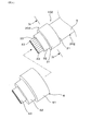
- the water stop cable 1 has a flat cable 2 and a rubber plug 3 attached to a terminal portion 21 of the flat cable 2.
- the flat cable 2 includes a plurality of cores 4 and a sheath 5 that collectively covers the plurality of cores 4.
- the core 4 includes one insulated wire 40 and / or a plurality of insulated wires 40, and is arranged in the cable width direction perpendicular to the longitudinal direction of the insulated wires 40.
- the sheath 5 includes an outer surface 400a of one of the cores 4 (4a, 4b), an outer surface 400b of the core 4b adjacent to the core 4a, and an inner surface of the sheath 5 An enclosed hollow portion 51 is formed.
- the sheath 5 includes a pair of sheath end portions 52 along the outer surfaces 400a and 400b of the cores 4a and 4b disposed at both ends of the plurality of cores 4, a connection portion 53 that connects the pair of sheath end portions 52, and a connection portion. 53 and a reinforcing portion 54 provided outside the portion of the connecting portion 53 that covers the hollow portion 51.
- the terminal portion 21 of the flat cable 2 has a sheath 5 and an insulated wire 40 protruding from the sheath 5.
- the rubber plug 3 includes a sheath covering portion 31 that covers the sheath 5, and a wire covering portion 32 that is connected to the sheath covering portion 31 and covers the protruding portion 43 of the insulated wire 40.
- a through hole 33 is formed in the wire covering portion 32, and the insulated wire 40 is inserted through the through hole 33.
- the flat cable 2 of the present example has two cores 4 inside a sheath 5.
- Each core 4 is a single-wire core composed of a single insulated wire 40 having a conductor 41 and an insulator 42 covering the conductor 41.
- the two cores 4 are arranged so that the insulators 42 are in contact with each other.
- the sheath end 52 has a semicircular shape in a cross section perpendicular to the longitudinal direction.
- the connection part 53 is exhibiting the linear form extended in a cable width direction in the said cross section.
- the reinforcing portion 54 is formed integrally with the connecting portion 53 and is provided over the entire connecting portion 53 in the cable width direction. Further, the thickness of the central portion 541 in the cable width direction of the reinforcing portion 54 is thicker than the thickness of the end portion 542 in the cable width direction.
- the outer surface 543 of the reinforcing portion 54 has an arc shape.
- the outer surface 510 of the sheath 5 has an elliptical shape. That is, in the cross section, the outer surface of the sheath end portion 52 and the outer surface of the reinforcing portion 54 are smoothly connected.
- the inner surface of the sheath 5 has an oval shape in which a pair of semicircles formed from the inner surface of the sheath end portion 52 and a straight line formed from the inner surface 500 of the connecting portion 53 are connected.
- the outer surface 510 of the sheath 5 is covered with the sheath covering portion 31 of the rubber plug 3.
- the sheath covering portion 31 of this example has a cylindrical shape corresponding to the outer shape of the sheath 5 and is in close contact with the sheath 5. Further, a surface pressure by the sheath covering portion 31 is applied to the outer surface 510 of the sheath 5.
- the rubber plug 3 of this example has two wire covering portions 32 that cover the core 4.
- the wire covering portion 32 extends from the sheath covering portion 31 in the longitudinal direction of the flat cable. Further, the wire covering portion 32 has a through hole 33 through which the insulated wire 40 is inserted. One end of the through hole 33 communicates with the inside of the sheath covering portion 31. Further, an insulated wire 40 extends from the other end of the through hole 33.
- the water stop cable 1 of this example can be applied to, for example, an application for connecting a brake device attached to a wheel and an electronic control unit attached to a vehicle body in the field of a vehicle such as an automobile.
- the sheath 5 includes a pair of sheath end portions 52, a connecting portion 53 that connects the pair of sheath end portions 52, and a reinforcing portion 54 that is provided outside the portion of the connecting portion 53 that covers the hollow portion 51. . Therefore, when the rubber plug 3 is attached to the terminal portion 21 of the flat cable 2, it is possible to suppress the portion of the sheath 5 that covers the hollow portion 51 from being depressed inside. Thereby, when the rubber plug 3 is attached to the terminal portion 21, a sufficient surface pressure can be applied to the outer surface of the sheath 5. As a result, the flat cable 2 can stop the terminal portion 21 with the rubber plug 3.
- the reinforcing portion 54 on the sheath 5 the surface pressure applied to the outer surface of the sheath 5 can be sufficiently increased even when the rubber plug 3 that does not match the shape of the sheath 5 is attached. Therefore, according to the flat cable 2, the common rubber plug 3 can be applied to various flat cables 2 having different shapes and sizes. As a result, it is possible to expect an effect of reducing labor and cost required for changing the shape of the rubber plug 3.
- the thickness of the central portion 541 of the reinforcing portion 54 in the cable width direction is thicker than the thickness of the end portion 542 in the cable width direction. Therefore, when the rubber plug 3 is attached to the terminal portion 21 of the flat cable 2, the surface pressure applied to the reinforcing portion 54 can be increased. As a result, the water stop performance can be further improved.
- the outer surface 543 of the reinforcing portion 54 has an arc shape. Therefore, the unevenness on the outer surface 543 of the reinforcing portion 54 can be reduced, and a gap is less likely to be formed between the rubber plug 3 and the reinforcing portion 54. As a result, the water stop performance can be further improved.
- the reinforcing portion 54 is provided over the entire connecting portion 53 in the cable width direction. Thereby, when the rubber plug 3 is attached to the terminal portion 21 of the flat cable 2, a sufficiently large surface pressure can be applied to the entire reinforcing portion 54. As a result, the water stop performance can be further improved.
- the outer surface 510 of the sheath 5 has an elliptical shape. Therefore, when the rubber plug 3 is attached to the end portion 21 of the flat cable 2, a gap is less likely to be formed between the rubber plug 3 and the sheath 5, and the outer surface of the sheath 5 is sufficiently large. Surface pressure can be applied. As a result, the water stop performance can be further improved.
- the flat cable 2 of this example can stop the terminal portion 21 with the rubber plug 3.
- the water stop cable 1 has a flat cable 2 and a rubber plug 3 attached to a terminal portion 21 of the flat cable 2.
- the sheath covering portion 31 presses against the sheath end portion 52 and the reinforcing portion 54, thereby suppressing entry of water or the like from between the sheath covering portion 31 and the sheath 5 into the inside of the sheath 5. can do.
- the wire covering portion 32 presses the protruding portion 43 of the insulated wire 40, it is possible to suppress intrusion of water or the like from between the wire covering portion 32 and the protruding portion 43 into the inside of the insulated wire 40. . Therefore, the water stop cable 1 of this example has excellent water stop performance.
- Example 2 This example is an example of the flat cable 202 and the water stop cable 102 in which the core 402 in the sheath 5 is a stranded core.
- the same reference numerals as those used in the above-described embodiments represent the same constituent elements as those in the above-described embodiments unless otherwise specified.
- the water stop cable 102 of this example has a flat cable 202 and a rubber plug 302 attached to the terminal portion 21 of the flat cable 202.
- two cores 402 are arranged in the sheath 5 of the flat cable 202.
- the core 402 of this example is a stranded wire core in which four insulated wires 40 are twisted together. Although not shown in the drawing, the twist of each core 402 is unwound at the terminal portion 21 of the flat cable 202. As a result, eight insulated wires 40 protrude from the sheath 5 at the terminal portion 21.
- the rubber plug 302 of this example includes a sheath covering portion 31 and one electric wire covering portion 32 connected to the sheath covering portion 31. As shown in FIG. 4, eight through holes 33 arranged in the cable width direction are formed in the wire covering portion 32. The insulated wire 40 is inserted through these through holes 33 and extends to the outside of the rubber plug 302 in a state of being aligned in the cable width direction.
- the water stop cable 102 of this example further includes a housing portion 6 attached to a rubber plug 302.
- the housing portion 6 includes a sheath pressing portion 61 that presses the sheath covering portion 31 inward, and an electric wire pressing portion 62 that presses the electric wire covering portion 32 inward.
- the sheath pressing portion 61 of this example has a cylindrical shape slightly smaller than the outer shape of the sheath covering portion 31. In a state where the housing portion 6 is attached to the rubber plug 302, the sheath covering portion 31 is covered with the sheath pressing portion 61.
- the electric wire pressing portion 62 extends from the sheath pressing portion 61 in the longitudinal direction of the flat cable 2 and has a cylindrical shape slightly smaller than the outer shape of the electric wire covering portion 32. In a state where the housing portion 6 is mounted on the rubber plug 302, the wire covering portion 32 is covered with the wire pressing portion 62.
- the housing portion 6 of this example further includes a cylindrical portion 63 that extends from the wire pressing portion 62 in the longitudinal direction of the flat cable 2.
- the insulated wire 40 extending from the through hole 33 of the rubber plug 302 is inserted into the cylindrical portion 63.
- Others are the same as in the first embodiment.
- the flat cable 202 can be water-stopped by using the rubber plug 302 by providing the reinforcing portion 54 on the sheath 502.
- the water stop cable 102 further includes a housing portion 6 including a sheath pressing portion 61 that presses the sheath covering portion 31 inward and an electric wire pressing portion 62 that presses the electric wire covering portion 32 inward.
- the sheath covering portion 31 can be securely adhered to the outer surface of the sheath 5, and the electric wire covering portion 32 can be reliably adhered to the outer surface of the insulated wire 40. Can do.
- the surface pressure added to the sheath 5 and the insulated wire 40 can be enlarged more. As a result, the water stop performance can be further improved.
- the flat cable 202 and the water stop cable 102 of this example can exhibit the same effects as those of the first embodiment.
- Example 3 This example is an example of the flat cable 203 and the water stop cable 103 in which a single wire core and a stranded wire core are mixed.
- the flat cable 203 of this example includes four cores 403 (403 a, 403 b, 403 c, and 403 d) arranged in the cable width direction and a sheath 503 that collectively covers the cores 403.
- the hollow portion 51 is formed inside the sheath 503.
- the two cores 403a and 403d arranged on the outer side in the cable width direction are single-wire cores composed of one insulated wire 40.
- the remaining two cores 403b and 403c are stranded wire cores composed of two insulated wires 40 twisted together. Others are the same as in the second embodiment.
- a single wire core and a stranded wire core may be mixed inside the sheath 303.
- the flat cable 203 and the water stop cable 103 of this example can exhibit the same effects as those of the second embodiment.
- Example 4 is an example of the flat cable 204 and the water stop cable 104 provided with the reinforcing portion 54 formed by being divided for each hollow portion 51.
- the flat cable 204 of this example includes four cores 4 (4 a, 4 b, 4 c, 4 d) arranged in the cable width direction and a sheath 504 that collectively covers the cores 4.
- the hollow portion 51 is formed inside the sheath 504.
- the core 4 of this example is a single wire core, as shown in FIG.
- the reinforcing portion 54 in the sheath 504 of this example is provided separately for each portion covering the hollow portion 51 in the connecting portion 53. That is, when the leftmost core 4 in FIG. 8 is the first core 4a, and the second core 4b, the third core 4c, and the fourth core 4d are sequentially formed from the core 4 close to the first core 4a, the first core 4a For each of the hollow portion 51a between the second core 4b, the hollow portion 51b between the second core 4b and the third core 4c, and the hollow portion 51c between the third core 4c and the fourth core 4d. A reinforcing portion 54 is provided.
- the thickness of the central portion 541 of the reinforcing portion 54 in the cable width direction is thicker than the thickness of the end portion 542 in the cable width direction.
- the outer surface 543 of the reinforcing portion 54 has an arc shape. Others are the same as in the second embodiment.
- the thickness of the central portion 541 of the reinforcing portion 54 in the cable width direction is thicker than the thickness of the end portion 542 in the cable width direction.
- the outer surface of the reinforcing portion 54 has an arc shape, so that a gap is less likely to be formed between the rubber plug 3 and the reinforcing portion 54. As a result, the water stop performance can be further improved.
- the flat cable and the water stop cable according to the present invention are not limited to the embodiments shown in Examples 1 to 4, and the configuration can be changed as appropriate without departing from the scope of the invention.
- the outer surface of the reinforcing portion 54 has an arc shape in a cross section perpendicular to the longitudinal direction of the flat cables 2, 202, 203, 204 is shown.
- the outer surface may be flat.
- the sheath pressing part 61 and the electric wire pressing part 62 showed the example which is exhibiting the cylindrical shape slightly thinner than the external shape of the sheath coating
- the sheath pressing portion 61 and the wire pressing portion 62 may be protrusions provided inside the housing portion 6. In this case, the sheath covering portion 31 and the wire covering portion 32 can be brought into close contact with the sheath 5 and the insulated wire 40 by pressing the sheath covering portion 31 and the wire covering portion 32 with the protrusions.
- the inner shape of the housing part 6 can be the same as the outer shape of the rubber plugs 3, 302, 303, 304.
- another member is provided outside the housing portion 6, and the sheath pressing portion that presses the sheath covering portion 31 and the wire covering portion 32 inward by pressing the housing portion 6 inward with the member. 61 and the electric wire pressing part 62 can be formed.
Landscapes
- Insulated Conductors (AREA)
- Connector Housings Or Holding Contact Members (AREA)
Abstract
ゴム栓(3)により端末部(21)の止水を行うことができるフラットケーブル(2)及びフラットケーブル(2)を備えた止水ケーブル(1)を提供する。フラットケーブル(2)は複数のコア(4)と、これらを一括して覆うシース(5)とを有している。コア(4)は1本または互いに撚り合わされた複数本の絶縁電線(40)を備え、ケーブル幅方向に並んでいる。シース(5)の内部には、いずれかのコア(4)の外表面と、当該コア(4)に隣り合うコア(4)の外表面と、シース(5)の内表面とにより囲まれた中空部(51)が形成されている。シース(5)は、複数のコア(4)のうち両端に配置されたコア(4)の外表面に沿って配置された一対のシース端部(52)と、一対のシース端部(52)を繋ぐ連結部(53)と、連結部(53)と一体に形成され、連結部(53)における中空部(51)を覆う部分の外側に設けられた補強部(54)とを有している。
Description
本発明は、フラットケーブル及び止水ケーブルに関する。
従来、種々の分野において、複数の絶縁電線と、これらの絶縁電線を一括して被覆するシースとを備えた多芯ケーブルが用いられている。この種の多芯ケーブルとして、長手方向に直交する断面の形状が扁平なフラットケーブルが知られている。フラットケーブルは円形の断面を有するケーブルに比べて柔軟であるため、配索のためのスペースが狭い箇所や、機器の使用中に繰り返し屈曲を受ける箇所等に用いられている。
フラットケーブルの端末からシースの内部、あるいは絶縁電線の内部に水や異物等が侵入すると、水分の凍結や異物による摩耗が生じ、絶縁電線の損傷を招くおそれがある。これらの問題を防止するため、フラットケーブルの端末部に止水処理が施されることがある。止水処理としては、例えば、端末部に存在する隙間にポッティング樹脂を充填する、端末部の外周をモールド樹脂により被覆する等の方法が多用されている。
また、シースの外周に密着するシース側リップと、絶縁電線の外周に密着する電線側リップとを備えたゴム栓を、断面が円形である多芯ケーブルの端末部に装着する技術も提案されている(特許文献1)。
しかし、ポッティング樹脂やモールド樹脂を用いて行う従来の止水処理は、工程数の増大を招くとともに各工程での所要時間も長くなりやすいため、工数が大きくなりやすい。また、従来の止水処理は、止水性能にバラつきが生じ易いため、高い止水性能を容易に確保する観点から未だ改善の余地がある。
また、フラットケーブルは、特許文献1のように断面が円形である多芯ケーブルとは異なり、シースの外表面にかかるゴム栓の面圧が均等になりにくい。例えば、シースの平坦部にかかる面圧は、ケーブル幅方向の両端部にかかる面圧に比べて低くなり易い。また、シースの平坦部は比較的剛性が低いため、ゴム栓の押圧力に耐え切れず、内側へ陥没しやすい。そして、シースの平坦部がこのように変形すると、シースの平坦部に加わる面圧がより低くなる。それ故、フラットケーブルの端末部に特許文献1のようなゴム栓を装着すると、ゴム栓とシースの平坦部との間からシースの内部あるいは絶縁電線の内部へ水等が侵入しやすいという問題がある。
本発明は、かかる背景に鑑みてなされたものであり、ゴム栓により端末部の止水を行うことができるフラットケーブル、及び、このフラットケーブルを備えた止水ケーブルを提供しようとするものである。
本発明の一態様は、1本の絶縁電線及び/または互いに撚り合わされた複数本の絶縁電線を備え、該絶縁電線の長手方向に直交するケーブル幅方向に並んだ複数のコアと、
複数の上記コアを一括して覆うシースと、
複数の上記コアのうちいずれかの上記コアの外表面と、当該コアに隣り合う上記コアの外表面と、上記シースの内表面とにより囲まれた中空部とを有し、
該シースは、
複数の上記コアのうち両端に配置された上記コアの外表面に沿う一対のシース端部と、
一対の上記シース端部間を繋ぐ連結部と、
該連結部と一体に形成されており、上記連結部における上記中空部を覆う部分の外側に設けられた補強部とを有している、フラットケーブルにある。
複数の上記コアを一括して覆うシースと、
複数の上記コアのうちいずれかの上記コアの外表面と、当該コアに隣り合う上記コアの外表面と、上記シースの内表面とにより囲まれた中空部とを有し、
該シースは、
複数の上記コアのうち両端に配置された上記コアの外表面に沿う一対のシース端部と、
一対の上記シース端部間を繋ぐ連結部と、
該連結部と一体に形成されており、上記連結部における上記中空部を覆う部分の外側に設けられた補強部とを有している、フラットケーブルにある。
本発明の他の態様は、上記の態様のフラットケーブルと、該フラットケーブルの端末部に装着されるゴム栓とを有する止水ケーブルであって、
上記端末部は、上記シースと、該シースから突出した上記絶縁電線とを有しており、
上記ゴム栓は、
上記シースを被覆するシース被覆部と、
該シース被覆部に連なり、上記絶縁電線の突出部を被覆する電線被覆部と、
該電線被覆部に形成され、上記突出部が挿通された貫通孔とを有している、止水ケーブルにある。
上記端末部は、上記シースと、該シースから突出した上記絶縁電線とを有しており、
上記ゴム栓は、
上記シースを被覆するシース被覆部と、
該シース被覆部に連なり、上記絶縁電線の突出部を被覆する電線被覆部と、
該電線被覆部に形成され、上記突出部が挿通された貫通孔とを有している、止水ケーブルにある。
上記フラットケーブルにおける上記シースは、一対の上記シース端部と、一対の上記シース端部を繋ぐ連結部と、該連結部における上記中空部を覆う部分の外側に設けられた上記補強部とを有している。上記シースにおける上記中空部を覆う部分は、上記連結部に加えて上記補強部を有しているため、上記フラットケーブルの端末部にゴム栓が装着された際に、上記シースにおける上記中空部を覆う部分が内側に陥没することを抑制することができる。そのため、上記フラットケーブルは、その端末部にゴム栓が装着された際に、上記シースの外表面に十分な大きさの面圧をかけることができる。その結果、上記フラットケーブルは、ゴム栓により端末部の止水を行うことができる。
また、上記シースに上記補強部を設けることにより、上記シースの形状に合致しないゴム栓を装着した場合であっても、上記シースの外表面に加わる面圧を十分に大きくすることができる。それ故、上記フラットケーブルによれば、形状や大きさが異なる種々の上記フラットケーブルに共通のゴム栓を適用することができる。その結果、ゴム栓の形状変更に要する手間や費用等を低減するという効果を期待することができる。
上記止水ケーブルは、上記の態様のフラットケーブルと、該フラットケーブルの端末部に装着された上記ゴム栓とを有している。上記止水ケーブルにおいては、上記シース被覆部が上記シース端部及び上記補強部を押圧することにより、上記シース被覆部と上記シースとの間から上記シースの内部等への水等の侵入を抑制することができる。また、上記電線被覆部が上記絶縁電線の上記突出部を押圧することにより、上記電線被覆部と上記突出部との間から上記絶縁電線の内部等への水等の侵入を抑制することができる。それ故、上記止水ケーブルは、優れた止水性能を有している。
上記フラットケーブルにおいて、各コアは、1本の絶縁電線からなる単線コアであってもよく、互いに撚り合わされた複数本の絶縁電線からなる撚線コアであってもよい。絶縁電線としては、導体と、導体を被覆する絶縁体とを備えた公知の絶縁電線を採用することができる。
シース内には、同一の構成を有するコアが配置されていてもよく、異なる構成を有するコアが混在していてもよい。例えば、シース内に2本のコアが配置されている場合、両方のコアが単線コアであってもよいし、両方のコアが撚線コアであってもよい。また、一方のコアを単線コアとし、他方のコアを撚線コアとすることもできる。シース内に3本以上のコアが配置されている場合にも、上記と同様に、全てのコアが単線コアである構成、全てのコアが撚線コアである構成及び単線コアと撚線コアとが混在している構成のいずれの構成を採用してもよい。
また、シース内に配置されるコアの外径は、同一であってもよく、互いに異なっていてもよい。なお、単線コアの外径は、コアを構成する絶縁電線の直径である。また、撚線コアの外径は、その長手方向の断面において、全ての絶縁電線を包含する外接円の直径である。
シースは、複数のコアのうち両端に配置されたコアの外表面に沿って配置された一対の上記シース端部と、一対の上記シース端部を繋ぐ連結部と、該連結部における上記中空部を覆う部分の外側に設けられた上記補強部とを有している。
上記ケーブル幅方向における上記補強部の中央部の肉厚は、上記ケーブル幅方向における端部の肉厚よりも厚くなっていてもよい。この場合には、フラットケーブルの端末部にゴム栓を装着した際に、補強部にかかる面圧をより大きくすることができる。その結果、止水性能をより向上させることができる。
また、フラットケーブルの長手方向に垂直な断面において、上記補強部の外表面は弧状を呈していてもよい。この場合には、補強部の外表面における凹凸を小さくすることができるため、ゴム栓と補強部との間に隙間がより形成されにくくなる。その結果、止水性能をより向上させることができる。
上記補強部は、上記ケーブル幅方向における上記連結部の全体にわたって設けられていることが好ましい。フラットケーブルの端末部にゴム栓を装着した場合、ゴム栓による面圧は、シース端部において最も高くなり、ケーブル幅方向におけるシースの中央へ向かうにつれて面圧が低くなる傾向がある。これに対し、ケーブル幅方向における上記連結部の全体にわたって補強部を配置することにより、補強部全体に十分に大きな面圧をかけることができる。その結果、止水性能をより向上させることができる。
また、上記フラットケーブルの長手方向に垂直な断面において、上記シースの外表面は楕円状を呈していることが好ましい。上記の「楕円状」には、楕円と、楕円に類する形状であって、シース端部の外表面を構成する曲線と、補強部の外表面を構成する曲線とが滑らかにつながっている形状が含まれる。楕円に類する形状としては、例えば、卵形や、長円形における平坦部分を外方に膨出させてなる形状などがある。シースの外表面に凹凸があり、凹部と凸部との境界線が明瞭に視認できる形状は、上記の「楕円状」からは除外される。
シースの形状を上記特定の形状とすることにより、フラットケーブルの端末部にゴム栓を装着した際に、ゴム栓とシースとの間に隙間がより形成されにくくなる。また、この場合には、シースの外表面に十分な大きさの面圧をかけることができる。その結果、止水性能をより向上させることができる。
なお、補強部は、上述したように、上記ケーブル幅方向における上記連結部の全体にわたって設けられていることが好ましいが、上記連結部における上記中空部を覆う部分ごとに分離して設けられていてもよい。
シースの材質としては、具体的には、例えば、ポリウレタン樹脂、塩化ビニル樹脂などを例示することができる。シースの材質としては、耐外傷性、耐磨耗性などの観点から、ポリウレタン樹脂を好適に用いることができる。
シースの内部には、複数のコアのうちいずれかのコアの外表面と、当該コアに隣り合うコアの外表面と、シースの内表面とにより囲まれた中空部が形成されている。中空部内には、紙類、ポリエチレン等のポリオレフィン樹脂、タルクなどからなる介在物が配置されていてもよい。中空部内に介在物を配置することにより、コア表面の凹凸を小さくすることができる。その結果、コア表面の凹凸に起因したシース外表面の凹凸をより小さくすることができ、うねり等の少ない良好な外観を有する自動車用複合ケーブルが得られる。
上記止水ケーブルは、上記フラットケーブルの端末部に存在するシースを除去して絶縁電線を露出させた後、当該端末部に上記ゴム栓を装着することにより作製することができる。上記ゴム栓は、上記シースの外表面を被覆するシース被覆部と、該シース被覆部に連なり、上記絶縁電線の突出部を被覆する電線被覆部と、該電線被覆部の先端に形成され、上記突出部を挿通する貫通孔とを有している。ゴム栓の材質としては、例えば、シリコーンゴムやポリウレタンゴムなどを例示することができる。
また、止水ケーブルは、ゴム栓を覆うハウジング部を更に有しており、ハウジング部は、シース被覆部を内側に押圧するシース押圧部と、電線被覆部を内側に押圧する電線押圧部を有していてもよい。この場合には、シース被覆部をシースの外表面に確実に密着させることができるとともに、電線被覆部を絶縁電線の外表面に確実に密着させることができる。それ故、止水性能をより向上させることができる。ハウジング部の材質としては、例えば、ポリブチレンテレフタレートやナイロンなどの硬質プラスチックを例示することができる。
(実施例1)
上記フラットケーブルを備えた止水ケーブルの実施例を、図を用いて説明する。図1に示すように、止水ケーブル1は、フラットケーブル2と、フラットケーブル2の端末部21に装着されたゴム栓3とを有している。図2に示すように、フラットケーブル2は、複数のコア4と、複数のコア4を一括して覆うシース5とを有している。コア4は、1本の絶縁電線40及び/または複数の絶縁電線40を備え、絶縁電線40の長手方向に直交するケーブル幅方向に並んでいる。シース5の内部には、複数のコア4(4a、4b)のうちいずれかのコア4aの外表面400aと、当該コア4aに隣り合うコア4bの外表面400bと、シース5の内表面とにより囲まれた中空部51が形成されている。
上記フラットケーブルを備えた止水ケーブルの実施例を、図を用いて説明する。図1に示すように、止水ケーブル1は、フラットケーブル2と、フラットケーブル2の端末部21に装着されたゴム栓3とを有している。図2に示すように、フラットケーブル2は、複数のコア4と、複数のコア4を一括して覆うシース5とを有している。コア4は、1本の絶縁電線40及び/または複数の絶縁電線40を備え、絶縁電線40の長手方向に直交するケーブル幅方向に並んでいる。シース5の内部には、複数のコア4(4a、4b)のうちいずれかのコア4aの外表面400aと、当該コア4aに隣り合うコア4bの外表面400bと、シース5の内表面とにより囲まれた中空部51が形成されている。
シース5は、複数のコア4のうち両端に配置されたコア4a、4bの外表面400a、400bに沿う一対のシース端部52と、一対のシース端部52を繋ぐ連結部53と、連結部53と一体に形成されており、連結部53における中空部51を覆う部分の外側に設けられた補強部54とを有している。
図1に示すように、フラットケーブル2の端末部21は、シース5と、シース5から突出した絶縁電線40とを有している。ゴム栓3は、シース5を被覆するシース被覆部31と、シース被覆部31に連なり、絶縁電線40の突出部43を被覆する電線被覆部32とを有している。電線被覆部32には貫通孔33が形成されており、貫通孔33には絶縁電線40が挿通されている。
図2に示すように、本例のフラットケーブル2は、シース5の内部に2本のコア4を有している。各コア4は、導体41と、導体41を被覆する絶縁体42とを備えた1本の絶縁電線40からなる単線コアである。また、2本のコア4は、絶縁体42同士が当接するようにして配置されている。
シース端部52は、長手方向に垂直な断面において半円状を呈している。また、連結部53は、当該断面においてケーブル幅方向に延びる直線状を呈している。補強部54は、連結部53と一体に形成されており、ケーブル幅方向における連結部53の全体にわたって設けられている。また、補強部54のケーブル幅方向における中央部541の肉厚は、ケーブル幅方向における端部542の肉厚よりも厚くなっている。さらに、フラットケーブル2の長手方向に垂直な断面において、補強部54の外表面543は弧状を呈している。
フラットケーブル2の長手方向に垂直な断面において、シース5の外表面510は楕円状を呈している。即ち、当該断面において、シース端部52の外表面と、補強部54の外表面とが滑らかに接続されている。シース5の内表面は、シース端部52の内表面からなる一対の半円と、連結部53の内表面500からなる直線とが接続された長円形を呈している。
シース5の外表面510は、ゴム栓3のシース被覆部31に覆われている。本例のシース被覆部31は、シース5の外形に対応した筒状を呈しており、シース5に密着している。また、シース5の外表面510にはシース被覆部31による面圧が印加されている。
本例のゴム栓3は、コア4を覆う2個の電線被覆部32を有している。電線被覆部32は、シース被覆部31からフラットケーブルの長手方向に延設されている。また、電線被覆部32は、絶縁電線40を挿通する貫通孔33を有している。貫通孔33の一端はシース被覆部31の筒内に連通している。また、貫通孔33の他端からは絶縁電線40が延出している。
本例の止水ケーブル1は、例えば、自動車等の車両の分野における、車輪に取り付けられたブレーキ装置と、車体に取り付けられた電子制御ユニットとを接続する用途等に適用することができる。
本例のフラットケーブル2及び止水ケーブル1の作用効果を説明する。シース5は、一対のシース端部52と、一対のシース端部52を繋ぐ連結部53と、連結部53における中空部51を覆う部分の外側に設けられた補強部54とを有している。それ故、フラットケーブル2の端末部21にゴム栓3が装着された際に、シース5における中空部51を覆う部分が内側に陥没することを抑制することができる。これにより、端末部21にゴム栓3が装着された際に、シース5の外表面に十分な大きさの面圧をかけることができる。その結果、フラットケーブル2は、ゴム栓3により端末部21の止水を行うことができる。
また、シース5に補強部54を設けることにより、シース5の形状に合致しないゴム栓3を装着した場合であっても、シース5の外表面に加わる面圧を十分に大きくすることができる。それ故、フラットケーブル2によれば、形状や大きさが異なる種々のフラットケーブル2に共通のゴム栓3を適用することができる。その結果、ゴム栓3の形状変更に要する手間や費用等を低減するという効果を期待することができる。
ケーブル幅方向における補強部54の中央部541の肉厚は、ケーブル幅方向における端部542の肉厚よりも厚くなっている。そのため、フラットケーブル2の端末部21にゴム栓3を装着した際に、補強部54にかかる面圧をより大きくすることができる。その結果、止水性能をより向上させることができる。
フラットケーブル2の長手方向に垂直な断面において、補強部54の外表面543は弧状を呈している。それ故、補強部54の外表面543における凹凸を小さくすることができ、ゴム栓3と補強部54との間に隙間がより形成されにくくなる。その結果、止水性能をより向上させることができる。
補強部54は、ケーブル幅方向における連結部53の全体にわたって設けられている。これにより、フラットケーブル2の端末部21にゴム栓3を装着した際に、補強部54全体に十分に大きな面圧をかけることができる。その結果、止水性能をより向上させることができる。
フラットケーブル2の長手方向に垂直な断面において、シース5の外表面510は楕円状を呈している。それ故、フラットケーブル2の端末部21にゴム栓3を装着した際に、ゴム栓3とシース5との間に隙間がより形成されにくくなるとともに、シース5の外表面に十分な大きさの面圧をかけることができる。その結果、止水性能をより向上させることができる。
以上のように、本例のフラットケーブル2は、ゴム栓3により端末部21の止水を行うことができる。
また、止水ケーブル1は、フラットケーブル2と、フラットケーブル2の端末部21に装着されたゴム栓3とを有している。止水ケーブル1においては、シース被覆部31がシース端部52及び補強部54を押圧することにより、シース被覆部31とシース5との間からシース5の内部等への水等の侵入を抑制することができる。また、電線被覆部32が絶縁電線40の突出部43を押圧することにより、電線被覆部32と突出部43との間から絶縁電線40の内部等への水等の侵入を抑制することができる。それ故、本例の止水ケーブル1は、優れた止水性能を有している。
(実施例2)
本例は、シース5内のコア402が撚線コアであるフラットケーブル202及び止水ケーブル102の例である。なお、本実施例以降において用いる符号のうち、既出の実施例において用いた符号と同一のものは、特に説明のない限り、既出の実施例における構成要素等と同様の構成要素等を表す。
本例は、シース5内のコア402が撚線コアであるフラットケーブル202及び止水ケーブル102の例である。なお、本実施例以降において用いる符号のうち、既出の実施例において用いた符号と同一のものは、特に説明のない限り、既出の実施例における構成要素等と同様の構成要素等を表す。
図3に示すように、本例の止水ケーブル102は、フラットケーブル202と、フラットケーブル202の端末部21に装着されたゴム栓302とを有している。図4に示すように、フラットケーブル202のシース5内には、2本のコア402が配置されている。本例のコア402は、4本の絶縁電線40が互いに撚り合わされてなる撚線コアである。図には示さないが、各コア402の撚りはフラットケーブル202の端末部21において解かれている。これにより、端末部21において、シース5から8本の絶縁電線40が突出している。
本例のゴム栓302は、シース被覆部31と、これに連なる1つの電線被覆部32とを有している。図4に示すように、電線被覆部32には、ケーブル幅方向に並んだ8個の貫通孔33が形成されている。絶縁電線40は、これらの貫通孔33に挿通されており、ケーブル幅方向に並んだ状態でゴム栓302の外部に延出している。
また、図3及び図4に示すように、本例の止水ケーブル102は、ゴム栓302に装着されたハウジング部6を更に有している。ハウジング部6は、シース被覆部31を内側に押圧するシース押圧部61と、電線被覆部32を内側に押圧する電線押圧部62とを有している。
本例のシース押圧部61は、シース被覆部31の外形よりもわずかに小さい筒状を呈している。ハウジング部6がゴム栓302に装着された状態において、シース被覆部31は、シース押圧部61により覆われている。
また、電線押圧部62は、シース押圧部61からフラットケーブル2の長手方向に延設されており、電線被覆部32の外形よりもわずかに小さい筒状を呈している。ハウジング部6がゴム栓302に装着された状態において、電線被覆部32は、電線押圧部62により覆われている。
本例のハウジング部6は、さらに、電線押圧部62からフラットケーブル2の長手方向に延設された筒状部63を有している。筒状部63には、ゴム栓302の貫通孔33から延出した絶縁電線40が挿通されている。その他は実施例1と同様である。
本例のように、撚線コアを用いる場合であっても、シース502に補強部54を設けることにより、ゴム栓302を用いてフラットケーブル202の止水処理を行うことができる。
また、止水ケーブル102は、シース被覆部31を内側に押圧するシース押圧部61と、電線被覆部32を内側に押圧する電線押圧部62とを備えたハウジング部6を更に有している。ハウジング部6をゴム栓302に装着することにより、シース被覆部31をシース5の外表面に確実に密着させることができるとともに、電線被覆部32を絶縁電線40の外表面に確実に密着させることができる。そして、シース5及び絶縁電線40に加わる面圧をより大きくすることができる。その結果、止水性能をより向上させることができる。その他、本例のフラットケーブル202及び止水ケーブル102は、実施例1と同様の作用効果を奏することができる。
(実施例3)
本例は、単線コアと撚線コアとが混在しているフラットケーブル203及び止水ケーブル103の例である。図5及び図6に示すように、本例のフラットケーブル203は、ケーブル幅方向に並んだ4本のコア403(403a、403b、403c、403d)と、コア403を一括して被覆するシース503とを有しており、シース503の内部には中空部51が形成されている。
本例は、単線コアと撚線コアとが混在しているフラットケーブル203及び止水ケーブル103の例である。図5及び図6に示すように、本例のフラットケーブル203は、ケーブル幅方向に並んだ4本のコア403(403a、403b、403c、403d)と、コア403を一括して被覆するシース503とを有しており、シース503の内部には中空部51が形成されている。
4本のコア403のうち、ケーブル幅方向の外側に配置された2本のコア403a、403dは、1本の絶縁電線40からなる単線コアである。また、残り2本のコア403b、403cは、互いに撚り合わされた2本の絶縁電線40からなる撚線コアである。その他は実施例2と同様である。
本例のように、シース303の内部には、単線コアと撚線コアとが混在していてもよい。本例のフラットケーブル203及び止水ケーブル103は、実施例2と同様の作用効果を奏することができる。
(実施例4)
本例は、中空部51ごとに分割して形成されている補強部54を備えたフラットケーブル204及び止水ケーブル104の例である。図7及び図8に示すように、本例のフラットケーブル204は、ケーブル幅方向に並んだ4本のコア4(4a、4b、4c、4d)と、コア4を一括して被覆するシース504とを有しており、シース504の内部には中空部51が形成されている。なお、本例のコア4は、図8に示すように、単線コアである。
本例は、中空部51ごとに分割して形成されている補強部54を備えたフラットケーブル204及び止水ケーブル104の例である。図7及び図8に示すように、本例のフラットケーブル204は、ケーブル幅方向に並んだ4本のコア4(4a、4b、4c、4d)と、コア4を一括して被覆するシース504とを有しており、シース504の内部には中空部51が形成されている。なお、本例のコア4は、図8に示すように、単線コアである。
図8に示すように、本例のシース504における補強部54は、連結部53における中空部51を覆う部分ごとに分離して設けられている。即ち、図8における最も左側のコア4を第1コア4aとし、第1コア4aに近いコア4から順に第2コア4b、第3コア4c及び第4コア4dとしたときに、第1コア4aと第2コア4bとの間の中空部51a、第2コア4bと第3コア4cとの間の中空部51b及び第3コア4cと第4コア4dとの間の中空部51cのそれぞれに対して補強部54が設けられている。
ケーブル幅方向における補強部54の中央部541の肉厚は、ケーブル幅方向における端部542の肉厚よりも厚くなっている。また、フラットケーブル204の長手方向に垂直な断面において、補強部54の外表面543は弧状を呈している。その他は実施例2と同様である。
本例のフラットケーブル204は、ケーブル幅方向における補強部54の中央部541の肉厚が、ケーブル幅方向における端部542の肉厚よりも厚くなっているため、フラットケーブル204の端末部21にゴム栓3を装着した際に、補強部54にかかる面圧をより大きくすることができる。その結果、止水性能をより向上させることができる。
また、フラットケーブル204の長手方向に垂直な断面において、補強部54の外表面が弧状を呈しているため、ゴム栓3と補強部54との間に隙間がより形成されにくくなる。その結果、止水性能をより向上させることができる。
なお、本発明に係るフラットケーブル及び止水ケーブルは、実施例1~4に示した態様に限定されるものではなく、その趣旨を損なわない範囲で適宜構成を変更することができる。例えば、実施例1~4には、フラットケーブル2、202、203、204の長手方向に垂直な断面において、補強部54の外表面が弧状を呈している例を示したが、補強部54の外表面は平坦であってもよい。
また、実施例2及び実施例3には、シース押圧部61及び電線押圧部62がシース被覆部31及び電線被覆部32の外形よりもわずかに細い筒状を呈している例を示したが、シース押圧部61及び電線押圧部62の形状を変更することも可能である。例えば、シース押圧部61及び電線押圧部62は、ハウジング部6の内側に設けた突起であってもよい。この場合、シース被覆部31及び電線被覆部32をこの突起で押圧することにより、シース被覆部31及び電線被覆部32をシース5及び絶縁電線40に密着させることができる。
また、ハウジング部6の内側の形状を、ゴム栓3、302、303、304の外形と同一の形状とすることもできる。この場合には、例えば、ハウジング部6の外側に別の部材を設け、当該部材でハウジング部6を内側に押圧することにより、シース被覆部31及び電線被覆部32を内側に押圧するシース押圧部61及び電線押圧部62を形成することができる。
Claims (7)
- 1本の絶縁電線及び/または互いに撚り合わされた複数の絶縁電線を備え、該絶縁電線の長手方向に直交するケーブル幅方向に並んだ複数のコアと、
複数の上記コアを一括して覆うシースと、
複数の上記コアのうちいずれかの上記コアの外表面と、当該コアに隣り合う上記コアの外表面と、上記シースの内表面とにより囲まれた中空部とを有し、
該シースは、
複数の上記コアのうち両端に配置された上記コアの外表面に沿う一対のシース端部と、
一対の上記シース端部間を繋ぐ連結部と、
該連結部と一体に形成されており、上記連結部における上記中空部を覆う部分の外側に設けられた補強部とを有している、フラットケーブル。 - 上記ケーブル幅方向における上記補強部の中央部の肉厚は、上記ケーブル幅方向における端部の肉厚よりも厚い、請求項1に記載のフラットケーブル。
- 上記フラットケーブルの長手方向に垂直な断面において、上記補強部の外表面は弧状を呈している、請求項2に記載のフラットケーブル。
- 上記補強部は、上記ケーブル幅方向における上記連結部の全体にわたって設けられている、請求項1~3のいずれか1項に記載のフラットケーブル。
- 上記フラットケーブルの長手方向に垂直な断面において、上記シースの外表面は楕円状を呈している、請求項1~4のいずれか1項に記載のフラットケーブル。
- 請求項1~5のいずれか1項に記載のフラットケーブルと、該フラットケーブルの端末部に装着されたゴム栓とを有する止水ケーブルであって、
上記端末部は、上記シースと、該シースから突出した上記絶縁電線とを有しており、
上記ゴム栓は、
上記シースを被覆するシース被覆部と、
該シース被覆部に連なり、上記絶縁電線の突出部を被覆する電線被覆部と、
該電線被覆部に形成され、上記突出部が挿通された貫通孔とを有している、止水ケーブル。 - 上記止水ケーブルは、上記ゴム栓を覆うハウジング部を更に有しており、該ハウジング部は、上記シース被覆部を内側に押圧するシース押圧部と、上記電線被覆部を内側に押圧する電線押圧部とを有している、請求項6に記載の止水ケーブル。
Priority Applications (3)
| Application Number | Priority Date | Filing Date | Title |
|---|---|---|---|
| DE112017002463.3T DE112017002463T5 (de) | 2016-05-13 | 2017-04-27 | Flachkabel und wasserdichtes Kabel |
| CN201780028988.4A CN109155168B (zh) | 2016-05-13 | 2017-04-27 | 扁形电缆及止水电缆 |
| US16/300,375 US10395796B2 (en) | 2016-05-13 | 2017-04-27 | Flat cable and waterproof cable |
Applications Claiming Priority (2)
| Application Number | Priority Date | Filing Date | Title |
|---|---|---|---|
| JP2016-097232 | 2016-05-13 | ||
| JP2016097232A JP6524961B2 (ja) | 2016-05-13 | 2016-05-13 | フラットケーブル及び止水ケーブル |
Publications (1)
| Publication Number | Publication Date |
|---|---|
| WO2017195640A1 true WO2017195640A1 (ja) | 2017-11-16 |
Family
ID=60267216
Family Applications (1)
| Application Number | Title | Priority Date | Filing Date |
|---|---|---|---|
| PCT/JP2017/016815 Ceased WO2017195640A1 (ja) | 2016-05-13 | 2017-04-27 | フラットケーブル及び止水ケーブル |
Country Status (5)
| Country | Link |
|---|---|
| US (1) | US10395796B2 (ja) |
| JP (1) | JP6524961B2 (ja) |
| CN (1) | CN109155168B (ja) |
| DE (1) | DE112017002463T5 (ja) |
| WO (1) | WO2017195640A1 (ja) |
Cited By (2)
| Publication number | Priority date | Publication date | Assignee | Title |
|---|---|---|---|---|
| NO20200395A1 (en) * | 2020-04-01 | 2021-10-04 | Insu El Tech As | Insulating plug, Method for Production and use thereof |
| US11215780B2 (en) | 2017-12-21 | 2022-01-04 | Fujikura Ltd. | Optical fiber cable |
Families Citing this family (4)
| Publication number | Priority date | Publication date | Assignee | Title |
|---|---|---|---|---|
| JP7321651B2 (ja) * | 2019-11-19 | 2023-08-07 | ホシデン株式会社 | 防水ケーブル、防水ケーブル製造方法 |
| JP7031723B1 (ja) * | 2020-12-08 | 2022-03-08 | Smk株式会社 | ケーブル用コネクタ及びケーブル用コネクタの製造方法 |
| US12413009B2 (en) | 2021-02-15 | 2025-09-09 | Raytheon Company | Cable assembly with integral seal element |
| WO2022208264A1 (en) * | 2021-03-31 | 2022-10-06 | 3M Innovative Properties Company | Transmission cable |
Citations (3)
| Publication number | Priority date | Publication date | Assignee | Title |
|---|---|---|---|---|
| JPS60161310U (ja) * | 1984-04-03 | 1985-10-26 | 三菱電線工業株式会社 | アンダ−カ−ペツトケ−ブル |
| JP2005100877A (ja) * | 2003-09-26 | 2005-04-14 | Yazaki Corp | 平型ケーブル |
| JP2011228043A (ja) * | 2010-04-16 | 2011-11-10 | Sumitomo Electric Ind Ltd | フラットケーブル |
Family Cites Families (17)
| Publication number | Priority date | Publication date | Assignee | Title |
|---|---|---|---|---|
| US4099038A (en) * | 1976-12-22 | 1978-07-04 | The United States Of America As Represented By The Secretary Of The Navy | Separable electrical flexible cable assembly for moving stores such as missiles |
| RU2201026C2 (ru) * | 1997-12-09 | 2003-03-20 | Дсг-Кануза Гмбх Унд Ко.Кг | Устройство и способ для удержания и направления удлиненных объектов |
| JP2002270313A (ja) * | 2001-03-09 | 2002-09-20 | Yazaki Corp | 補機モジュール用中継部品および補機モジュール |
| US7354308B2 (en) * | 2005-08-03 | 2008-04-08 | Yazaki Corporation | Waterproof connector for flat cable |
| JP4970093B2 (ja) * | 2006-08-01 | 2012-07-04 | 矢崎総業株式会社 | 取付構造 |
| US20100080520A1 (en) * | 2008-05-12 | 2010-04-01 | Howard Lind | Flexible silicone cable system integrated with hollow tubing for fluid delivery |
| US8595922B2 (en) * | 2008-05-12 | 2013-12-03 | Howard Lind | Flexible silicone cable system integrated with snap washer |
| JP5015064B2 (ja) * | 2008-05-26 | 2012-08-29 | 株式会社潤工社 | 封止部材付ケーブル |
| JP4898936B2 (ja) * | 2010-03-31 | 2012-03-21 | 株式会社フジクラ | 防水コネクタ |
| TW201205605A (en) * | 2010-07-22 | 2012-02-01 | Adv Flexible Circuits Co Ltd | Flexible flat cable with waterproof structure |
| JP5603695B2 (ja) * | 2010-07-26 | 2014-10-08 | 矢崎総業株式会社 | 防水コネクタ |
| JP5654382B2 (ja) * | 2011-02-25 | 2015-01-14 | 矢崎総業株式会社 | フラット回路用コネクタ |
| JP2013038039A (ja) * | 2011-08-11 | 2013-02-21 | Yazaki Corp | フラットケーブル防水コネクタおよびその製造方法 |
| CN202711774U (zh) * | 2012-06-05 | 2013-01-30 | 安徽华联电缆集团有限公司 | 一种行车用扁电缆 |
| JP5862709B2 (ja) | 2014-06-26 | 2016-02-16 | 株式会社オートネットワーク技術研究所 | シール部材、及び多芯ケーブルのシール構造 |
| EP3579540A1 (en) * | 2015-03-04 | 2019-12-11 | SONY Corporation | Imaging device |
| CN107925177B (zh) * | 2015-09-02 | 2020-03-03 | 古河电气工业株式会社 | 防水连接结构、连接结构体以及分隔部件 |
-
2016
- 2016-05-13 JP JP2016097232A patent/JP6524961B2/ja not_active Expired - Fee Related
-
2017
- 2017-04-27 US US16/300,375 patent/US10395796B2/en active Active
- 2017-04-27 DE DE112017002463.3T patent/DE112017002463T5/de not_active Withdrawn
- 2017-04-27 CN CN201780028988.4A patent/CN109155168B/zh not_active Expired - Fee Related
- 2017-04-27 WO PCT/JP2017/016815 patent/WO2017195640A1/ja not_active Ceased
Patent Citations (3)
| Publication number | Priority date | Publication date | Assignee | Title |
|---|---|---|---|---|
| JPS60161310U (ja) * | 1984-04-03 | 1985-10-26 | 三菱電線工業株式会社 | アンダ−カ−ペツトケ−ブル |
| JP2005100877A (ja) * | 2003-09-26 | 2005-04-14 | Yazaki Corp | 平型ケーブル |
| JP2011228043A (ja) * | 2010-04-16 | 2011-11-10 | Sumitomo Electric Ind Ltd | フラットケーブル |
Cited By (3)
| Publication number | Priority date | Publication date | Assignee | Title |
|---|---|---|---|---|
| US11215780B2 (en) | 2017-12-21 | 2022-01-04 | Fujikura Ltd. | Optical fiber cable |
| NO20200395A1 (en) * | 2020-04-01 | 2021-10-04 | Insu El Tech As | Insulating plug, Method for Production and use thereof |
| NO346126B1 (en) * | 2020-04-01 | 2022-03-07 | Insu El Tech As | Insulating plug, method for production and use thereof |
Also Published As
| Publication number | Publication date |
|---|---|
| JP2017204445A (ja) | 2017-11-16 |
| US20190131031A1 (en) | 2019-05-02 |
| US10395796B2 (en) | 2019-08-27 |
| DE112017002463T5 (de) | 2019-01-31 |
| JP6524961B2 (ja) | 2019-06-05 |
| CN109155168B (zh) | 2020-04-10 |
| CN109155168A (zh) | 2019-01-04 |
Similar Documents
| Publication | Publication Date | Title |
|---|---|---|
| WO2017195640A1 (ja) | フラットケーブル及び止水ケーブル | |
| US9496071B2 (en) | Shield wire | |
| US10483665B2 (en) | Ground terminal and wire harness | |
| US10692628B2 (en) | Wiring member | |
| EP3226254B1 (en) | Fluororesin cable and electronic device | |
| US20150207258A1 (en) | Connecting cable | |
| JP3389577B1 (ja) | 多芯シースケーブルの端末部の防水構造及びその形成方法 | |
| JP6089141B1 (ja) | 複合型電線 | |
| JP5166841B2 (ja) | 保護部材 | |
| JP2023038467A (ja) | ワイヤハーネス及びケーブルの防水構造 | |
| JP2023021126A (ja) | ワイヤハーネス | |
| JP4984626B2 (ja) | 電気ケーブル | |
| JP7236618B2 (ja) | ワイヤハーネス | |
| JP2014229586A (ja) | ワイヤハーネス | |
| JP7236617B2 (ja) | ワイヤハーネス | |
| JP2007027040A (ja) | 電気ケーブル | |
| JP7772132B2 (ja) | 配線モジュール及び弾性止水部材 | |
| JP2015139306A (ja) | 電線モジュール | |
| JP7746775B2 (ja) | 多芯ケーブル | |
| JP2025012328A (ja) | ワイヤハーネス | |
| JP7196784B2 (ja) | ワイヤハーネス | |
| US20230238158A1 (en) | Wiring module and elastic waterproofing member | |
| JP2025170945A (ja) | ワイヤハーネス | |
| JP2023141870A (ja) | ワイヤハーネス | |
| JP2017055569A (ja) | 止水部材及びワイヤハーネス |
Legal Events
| Date | Code | Title | Description |
|---|---|---|---|
| 121 | Ep: the epo has been informed by wipo that ep was designated in this application |
Ref document number: 17796001 Country of ref document: EP Kind code of ref document: A1 |
|
| 122 | Ep: pct application non-entry in european phase |
Ref document number: 17796001 Country of ref document: EP Kind code of ref document: A1 |