WO2017195364A1 - 情報処理装置及びケース - Google Patents
情報処理装置及びケース Download PDFInfo
- Publication number
- WO2017195364A1 WO2017195364A1 PCT/JP2016/064354 JP2016064354W WO2017195364A1 WO 2017195364 A1 WO2017195364 A1 WO 2017195364A1 JP 2016064354 W JP2016064354 W JP 2016064354W WO 2017195364 A1 WO2017195364 A1 WO 2017195364A1
- Authority
- WO
- WIPO (PCT)
- Prior art keywords
- case
- information processing
- processing apparatus
- insulating structure
- heat insulating
- Prior art date
- Legal status (The legal status is an assumption and is not a legal conclusion. Google has not performed a legal analysis and makes no representation as to the accuracy of the status listed.)
- Ceased
Links
Images









Classifications
-
- H—ELECTRICITY
- H05—ELECTRIC TECHNIQUES NOT OTHERWISE PROVIDED FOR
- H05K—PRINTED CIRCUITS; CASINGS OR CONSTRUCTIONAL DETAILS OF ELECTRIC APPARATUS; MANUFACTURE OF ASSEMBLAGES OF ELECTRICAL COMPONENTS
- H05K7/00—Constructional details common to different types of electric apparatus
- H05K7/20—Modifications to facilitate cooling, ventilating, or heating
Definitions
- the technology disclosed by the present application relates to an information processing apparatus and a case.
- the vacuum heat insulating structure is disposed between the electronic component and the case, the case may be enlarged.
- the technology disclosed in the present application is aimed at reducing the size of the case as one aspect.
- an information processing apparatus includes an electronic component, and a case that has an outer surface exposed to the outside and has a vacuum heat insulating structure that faces the electronic component and accommodates the electronic component.
- the case can be miniaturized as one aspect.
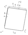
- FIG. 1 is a front view showing the information processing apparatus according to the first embodiment.
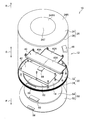
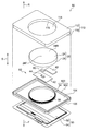
- FIG. 2 is an exploded perspective view of the information processing apparatus shown in FIG. 1 viewed from the back side.
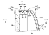
- 3 is a cross-sectional view taken along line F3-F3 of FIG. 4A is a partially enlarged view of FIG.
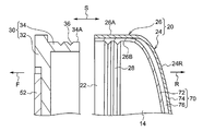
- FIG. 4B is a cross-sectional view showing a state in which the rear side split case and the front side split case shown in FIG. 4A are disassembled.
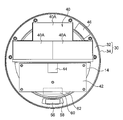
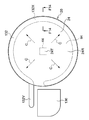
- FIG. 5 is a rear view showing the front side split case shown in FIG. 2.
- FIG. 6 is a partially enlarged view of FIG.
- FIG. 7 is an enlarged view corresponding to FIG. 6 showing a modification of the information processing apparatus according to the first embodiment.
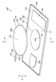
- FIG. 8 is a perspective view of the information processing apparatus according to the second embodiment as viewed from the front side.
- FIG. 9 is a perspective view of the information processing apparatus shown in FIG. 8 as viewed from the back side.
- FIG. 10 is an exploded perspective view of the information processing apparatus shown in FIG. 9 as viewed from the back side.
- 11 is a cross-sectional view taken along line F11-F11 in FIG.
- FIG. 12 is an exploded perspective view of the information processing apparatus according to the third embodiment as viewed from the back side.
- FIG. 13 is a rear view showing the rear side divided case, the heat pipe, and the cooler shown in FIG. 12.
- 14 is a cross-sectional view taken along line F14-F14 in FIG.
- FIG. 15 is a perspective view of one end of the heat pipe shown in FIG.
- FIG. 16 is a perspective view of one end portion of the heat pipe shown in FIG. 13 as viewed from the front side.
- FIG. 17 is a perspective view of the information processing apparatus according to the fourth embodiment as viewed from the front side.
- 18 is a perspective view of the information processing apparatus shown in FIG. 17 as viewed from the back side.
- FIG. 19 is an exploded perspective view of the information processing apparatus shown in FIG. 17 as viewed from the front side.
- 20 is a cross-sectional view taken along line F20-F20 in FIG.
- the information processing apparatus 10 is, for example, a mobile terminal such as a tablet terminal. Further, the information processing apparatus 10 is formed in a disk shape. As shown in FIGS. 2 and 3, the information processing apparatus 10 includes a case 12 and a touch panel module 50.
- an arrow F shown in each figure indicates the front side of the information processing apparatus 10 and the case 12.
- An arrow R indicates the back side of the information processing apparatus 10 and the case 12.
- the arrow S indicates the thickness direction of the information processing apparatus 10 and the case 12.
- Case 12 is formed in a disk shape. Moreover, as FIG. 3 shows, the case 12 has the storage chamber 14 inside.
- the case 12 includes a rear side divided case 20 and a front side divided case 30 that are divided in the thickness direction (arrow S direction) of the case 12 (information processing apparatus 10).
- the back side split case 20 and the front side split case 30 form a storage chamber 14 inside in a state where they are combined with each other.
- An electronic component 44 described later is accommodated in the accommodation chamber 14.
- the rear side split case 20 is an example of a first split case.
- segmentation case 30 is an example of a 2nd division
- the back side split case 20 is formed in a box shape having a storage port 22 (see FIG. 4B) on the front side split case 30 side. Electronic components 44 and the like are accommodated in the accommodating chamber 14 in the rear side split case 20 from the accommodating port 22.
- the back side split case 20 is formed by a pair of an inner plate 72 and an outer plate 74 described later.
- the rear side split case 20 has a bottom wall portion 24 and a side wall portion 26.
- the bottom wall portion 24 has a circular shape when viewed from the thickness direction of the bottom wall portion 24.
- the outer surface 24R of the bottom wall portion 24 is exposed to the outside of the information processing apparatus 10 (case 12).
- a central portion 24R1 (see FIG. 2) of the outer surface 24R of the bottom wall portion 24 is a flat surface that is installed on an installation surface (not shown) such as a desk.
- the bottom wall portion 24 has a facing portion 24T facing the electronic component 44.
- the facing portion 24T is located at the center of the bottom wall portion 24.
- segmentation case 20 is an example of the wall part of a case.
- the side wall portion 26 extends from the outer peripheral portion of the bottom wall portion 24 toward the front-side split case 30 and is formed in a cylindrical shape (cylindrical shape) along the outer peripheral portion of the bottom wall portion 24. Further, the outer peripheral surface 26 ⁇ / b> A of the side wall portion 26 is exposed to the outside of the information processing apparatus 10. As shown in FIGS. 4A and 4B, a female screw portion 28 is formed on the inner peripheral surface 26 ⁇ / b> B (the inner peripheral surface 26 ⁇ / b> B of the storage port 22) on the side of the storage port 22 of the side wall portion 26. The female screw portion 28 is cut with a female screw extending in a spiral shape.
- the front side divided case 30 is formed of, for example, metal or resin.
- the front side divided case 30 is attached to the rear side divided case 20 so as to be able to open and close the accommodation port 22 (see FIG. 4B) of the rear side divided case 20.
- the front side divided case 30 includes a case main body portion 32 and a connecting portion 34.
- the case body part (front side divided case body part) 32 is formed in a circular shape.
- the case main body 32 faces the bottom wall 24 of the rear side divided case 20.
- the case main body portion 32 is provided with a connecting portion 34.
- the connecting portion 34 extends from the outer peripheral portion of the case main body portion 32 toward the rear side divided case 20 and is formed in a cylindrical shape (cylindrical shape) along the outer peripheral portion of the case main body portion 32.
- a male screw portion 36 is provided on the outer peripheral surface 34 ⁇ / b> A of the connecting portion 34.
- the male screw portion 36 is cut with a male screw extending in a spiral shape.
- the female screw portion 28 of the rear side split case 20 is fastened to the male screw portion 36. Thereby, the front side divided case 30 and the rear side divided case 20 are joined in a combined state, and the accommodation chamber 14 is formed between the front side divided case 30 and the rear side divided case 20.
- a battery 40, a printed circuit board 42, and an antenna module 46 are accommodated in the accommodation chamber 14.
- the battery 40 has, for example, three cells 40A.
- the printed circuit board 42 is formed in a plate shape.
- An electronic component 44 such as a CPU is mounted on the printed circuit board (main board) 42.
- the electronic component 44 faces the facing portion 24T of the bottom wall portion 24 of the back side divided case 20.
- the battery 40 and the antenna module 46 are electrically connected to the printed circuit board 42 via a wiring (not shown).
- the battery 40 supplies power to the electronic component 44 mounted on the printed circuit board 42.
- the electronic component 44 generates heat by consuming electricity supplied from the battery 40.
- a plurality of electronic components (not shown) such as a memory are mounted on the printed circuit board 42.
- the antenna module 46 is, for example, an antenna for wireless communication. As shown in FIG. 5, the antenna module 46 is accommodated in the outer peripheral portion of the accommodation chamber 14 so as not to overlap the battery 40 and the printed circuit board 42. Thereby, the influence of the radio wave etc. emitted from the battery 40 and the printed circuit board 42 is reduced with respect to the wireless communication of the antenna module 46.
- a touch panel module 50 is attached to the opposite side of the front side split case 30 with respect to the front side split case 30.
- the touch panel module 50 includes a touch panel 52 and a display 54.
- the touch panel 52 is formed in a circular shape.
- the outer surface of the touch panel 52 is an operation surface 52F on which a user performs a touch operation with a finger or the like.
- the touch panel 52 is provided with a touch panel substrate 56 that controls the touch panel 52.
- the touch panel substrate 56 is accommodated in an opening 58 formed in the outer peripheral portion of the case main body 32 of the front side divided case 30.
- the display 54 is disposed between the touch panel 52 and the front side split case 30.
- the display 54 is, for example, a liquid crystal panel that displays an image, video, or the like on the operation surface 52F of the touch panel 52.
- the display device 54 is provided with a display substrate 60 for controlling the display device 54.
- the display substrate 60 is accommodated in an opening 62 formed in the case main body 32 of the front side divided case 30.
- the rear side split case 20 has a vacuum heat insulating structure 70.
- the back side divided case 20 is formed by a pair of inner plate 72 and outer plate 74.
- the inner plate 72 is formed of a metal plate such as aluminum having thermal conductivity.
- the outer plate 74 is formed of a metal plate, a resin plate, glass, or the like regardless of the presence or absence of thermal conductivity.
- the inner plate 72 is not limited to a metal plate or the like, and may be formed of a resin plate or glass.
- the pair of inner plates 72 and outer plates 74 are airtightly brazed (brazed) at the outer peripheral portions of the inner plate 72 and the outer plate 74 with their central portions facing each other.
- a sealed space 76 is formed between the center portion of the pair of inner plates 72 and the center portion of the outer plate 74.
- the sealed space 76 insulates the inner plate 72 and the outer plate 74 from each other. Further, the sealed space 76 is evacuated. Thereby, the heat insulation performance of the sealed space 76 is improved.
- the “brazing” is a concept including welding and solder joint.
- FIG. The vacuum heat insulating structure 70 is arranged on the opposite side of the case 12 from the indicator 54.
- the vacuum heat insulating structure 70 constitutes the bottom wall portion 24 of the back side split case 20.
- the vacuum heat insulating structure 70 constitutes a facing portion 24T of the bottom wall portion 24. Thereby, the heat transmitted from the electronic component 44 to the outer surface 24R of the facing portion 24T is reduced by the sealed space 76 of the vacuum heat insulating structure 70.
- the information processing apparatus 10 includes the case 12 that houses the electronic component 44.
- the case 12 includes a back side split case 20 and a front side split case 30.
- the rear side split case 20 has a bottom wall portion 24 whose outer surface 24R is exposed to the outside of the information processing apparatus 10.
- the electronic component 44 is opposed to the facing portion 24T of the bottom wall portion 24.
- the temperature of the bottom wall portion 24 of the rear-side split case 20 is likely to rise.
- the temperature of the facing portion 24T of the bottom wall portion 24 facing the electronic component 44 is likely to rise.
- the facing portion 24T of the bottom wall portion 24 is configured by the vacuum heat insulating structure portion 70.
- the heat transmitted from the electronic component 44 to the outer surface 24R of the facing portion 24T is insulated by the sealed space 76 of the vacuum heat insulating structure 70.
- the temperature rise of the outer surface 24R of the facing portion 24T is suppressed. Therefore, the discomfort felt by the user when the user touches the outer surface 24R of the facing portion 24T is reduced.
- the vacuum heat insulating structure 70 constitutes the bottom wall 24 of the back side divided case 20.
- the case 12 can be made thin.
- the case 12 can be thinned while reducing the heat transmitted from the electronic component 44 to the outer surface 24R of the bottom wall portion 24 of the rear side divided case 20.
- the facing portion 24T of the bottom wall portion 24 is located at the center of the bottom wall portion 24 that is easy for the user to touch.
- the facing portion 24T is configured by the vacuum heat insulating structure 70 as described above. Thereby, the discomfort felt by the user can be effectively reduced.
- the vacuum heat insulating structure 70 constitutes not only the facing portion 24T of the bottom wall portion 24 but the entire bottom wall portion 24. Thereby, the temperature rise of the outer surface 24R of the bottom wall part 24 is suppressed over the entire surface of the outer surface 24R. Therefore, the discomfort felt by the user is further reduced.
- the inner plate 72 of the vacuum heat insulating structure 70 is formed of a metal plate having thermal conductivity.
- the heat transmitted from the electronic component 44 to the inner plate 72 of the facing portion 24 ⁇ / b> T is diffused and transmitted to the entire inner plate 72. Therefore, the temperature rise of the outer surface 24R of the facing portion 24T is further suppressed.
- the vacuum heat insulating structure 70 is formed in a circular shape when viewed from the thickness direction of the vacuum heat insulating structure 70. Thereby, when the sealed space 76 is evacuated, the stress is suppressed from being concentrated on a predetermined portion of the vacuum heat insulating structure 70. Therefore, since the inner plate 72 and the outer plate 74 can be thinned, the case 12 can be thinned.
- a heat conducting member 80 is provided between the facing portion 24T of the bottom wall portion 24 of the back side split case 20 and the electronic component 44.
- the facing portion 24T of the bottom wall portion 24 faces the electronic component 44 with the heat conducting member 80 interposed therebetween.
- heat conductive member (heat radiating member) 80 for example, a heat conductive rubber, a heat conductive grease, or a heat conductive sheet having a high heat conductivity is used.
- the electronic component 44 is brought into contact with the inner plate 72 of the facing portion 24T via the heat conducting member 80. Thereby, the heat of the electronic component 44 is transmitted to the inner plate 72 of the bottom wall portion 24 through the heat conducting member 80. As a result, the efficiency of transmission of heat transmitted from the electronic component 44 to the inner plate 72 of the facing portion 24T is increased.
- the inner plate 72 has thermal conductivity as described above. As a result, the heat transferred from the electronic component 44 to the inner plate 72 is diffused over a wide area of the inner plate 72 as indicated by an arrow a. Therefore, in this modification, the temperature rise of the outer surface 24R of the facing portion 24T of the bottom wall portion 24 is further suppressed as compared with the case where the heat conducting member 80 is not provided.
- the information processing apparatus 90 is a mobile terminal such as a tablet terminal, for example.
- This information processing apparatus 90 is formed in a flat rectangular parallelepiped shape.
- the information processing apparatus 90 includes a case 92, a touch panel module 50, and a back side cover 110.
- the case 92 has a storage chamber 94 inside.
- the case 92 includes a rear side split case 20 and a front side split case 100 that are split in the thickness direction (arrow S direction) of the case 92.
- the back side split case 20 and the front side split case 100 form a storage chamber 94 inside in a state of being combined with each other.
- the accommodation chamber 94 is a hermetically sealed chamber.
- the storage chamber 94 stores the battery 40, the printed circuit board 42, and the electronic component 44.
- the electronic component 44 of the present embodiment is brought into contact with the inner plate 72 of the bottom wall portion 24 of the rear side divided case 20 via the heat conducting member 80.
- the side wall part 26 of the back side split case 20 of this embodiment has the side wall side vacuum heat insulation structure part 71.
- the side wall-side vacuum heat insulating structure 71 is formed by an inner plate 72, an outer plate 74, and a sealed space 76 in the same manner as the vacuum heat insulating structure 70 constituting the bottom wall portion 24 of the back side divided case 20.
- the front side divided case 100 is formed of, for example, metal or resin.
- the front side divided case 100 includes a case main body 102 and a connecting portion 34.
- the case main body portion (front-side divided case main body portion) 102 has a bottom wall portion 104 and a side wall portion 106.
- the bottom wall portion 104 is formed in a rectangular shape.
- a touch panel module 50 is provided on the front side of the bottom wall portion 104.
- the touch panel 52 of the touch panel module 50 is formed in a rectangular shape.
- a connecting portion 34 that extends toward the back side split case 20 is provided at the center of the bottom wall portion 104.
- the male screw portion 36 of the connecting portion 34 is fastened to the female screw portion 28 of the rear side split case 20.
- the bottom wall portion 104 of the case main body portion 102 projects outward from the side wall portion 26 of the back side divided case 20.
- a side wall portion 106 extending to the back side is provided on the outer peripheral portion of the bottom wall portion 104.
- a back cover 110 is attached to the front split case 100 of the case 92.
- the back side cover 110 is formed in a box shape having an open front side.
- the back side cover 110 has a bottom wall portion 112 and a side wall portion 118.
- the back side cover 110 is an example of a cover.
- the bottom wall portion 112 is formed in a rectangular shape.
- An exposure opening 114 is formed in the center portion of the bottom wall portion 112.
- the exposure opening 114 is a circular through hole that penetrates the bottom wall portion 112 in the thickness direction.
- the bottom wall 24 of the rear side split case 20 is disposed in the exposure opening 114. Thereby, the outer surface 24 ⁇ / b> R of the bottom wall portion 24 of the rear side split case 20 is exposed from the exposure opening 114.
- the outer surface 112 ⁇ / b> R of the bottom wall portion 112 of the back side cover 110 and the bottom of the back side split case 20 is flush with the outer surface 24R. That is, the outer surface 112R of the bottom wall portion 112 of the back side cover 110 and the outer surface of the vacuum heat insulating structure 70 are flush with each other.
- level here refers to a state in which the outer surface 24R of the bottom wall portion 24 and the outer surface 112R of the bottom wall portion 112 are slightly shifted due to manufacturing errors of the rear side split case 20 and the rear side cover 110. It is a concept that includes.
- a rib 116 extending to the front side is provided at the peripheral edge of the exposed opening 114.
- the rib 116 is formed in a cylindrical shape (cylindrical shape).
- the rear side split case 20 is fitted inside the rib 116. Thereby, the position shift of the back side division
- the side wall part 118 of the back side cover 110 extends from the outer peripheral part of the bottom wall part 112 to the front side.
- the side wall 118 is joined in a state of being combined with the side wall 106 of the front side split case 100.
- a storage chamber 111 is formed between the back cover 110 and the front split case 100 for storing connectors, wiring, etc. (not shown).
- the case 92 has a storage chamber 94 therein.
- An electronic component 44 is accommodated in the accommodation chamber 94.
- the electronic component 44 when the electronic component 44 generates heat, air in the storage chamber 94 heated by the electronic component 44 is convected. When this heated air flows out of the storage chamber 94, for example, the components around the storage chamber 94 may be heated. Further, if the air flowing out of the storage chamber 94 hits the user's hand, the user may feel uncomfortable.
- the storage chamber 94 of the present embodiment is a sealed chamber.
- the air heated by the electronic component 44 does not flow out of the storage chamber 94 to the outside. Therefore, the air heated by the electronic component 44 is prevented from hitting the peripheral components of the storage chamber 94 and the user's hand. Therefore, the temperature rise of the parts around the storage chamber 94 is suppressed, and the discomfort experienced by the user is reduced.
- the side wall portion 26 of the rear side divided case 20 is configured by the side wall side vacuum heat insulating structure portion 71.
- heat of the electronic component 44 and the like transmitted from the storage chamber 94 to the outer peripheral surface 26A of the side wall portion 26 is insulated by the sealed space 76 of the side wall-side vacuum heat insulating structure portion 71. Therefore, the temperature rise of components around the storage chamber 94 is further suppressed.
- the sidewall-side vacuum heat insulating structure 71 can constitute at least a part of the sidewall 26.
- the back cover 110 is attached to the case 92.
- An exposure opening 114 is formed in the bottom wall portion 112 of the back side cover 110.
- the bottom wall 24 of the rear side split case 20 is disposed in the exposure opening 114.
- the outer surface 24R of the bottom wall portion 24 of the rear side split case 20 and the outer surface 112R of the bottom wall portion 112 of the rear side cover 110 are flush with each other. Therefore, the designability of the information processing apparatus 90 can be improved while reducing the thickness of the information processing apparatus 90.
- the information processing apparatus 120 includes a heat pipe 130 and a cooler 136 that cool the rear side split case 20.
- the heat pipe 130 includes a flat pipe member 132 whose inside is evacuated and a working fluid (not shown) sealed in the pipe member 132.
- the battery 40 is accommodated in the accommodating chamber 11 outside the rear side split case 20.
- the illustration of the back side cover 110 is omitted.
- the pipe material 132 includes an evaporation section 132X and a condensation section 132Y.
- the evaporation part 132X is curved in an arc shape along the outer peripheral part of the rear side split case 20.
- the electronic component 44 is surrounded by the evaporation unit 132X over a half circumference.
- the evaporation section 132X is brazed to the inner plate 72 of the rear side split case 20 so that heat exchange is possible. Thereby, the evaporation part 132X is heated by the heat of the inner plate 72.
- the evaporation part 132X of this embodiment is joined to the inner plate 72 via the brazing material 133.
- the female screw part 28 is not provided in the back side division
- the rear side split case 20 is brazed to the connecting portion 34 of the front side split case 100.
- the condensing part 132Y is provided at one end of the pipe material 132 as shown in FIGS.
- the condensing part 132 ⁇ / b> Y extends to the outside of the storage chamber 94 from a notch-shaped entrance / exit 134 formed in the side wall part 26 of the rear side split case 20.
- the condensing unit 132Y is opposed to the cooler 136.
- the cooler 136 is housed in a housing chamber 111 (see FIG. 12) formed between the front-side divided case 100 and the back-side cover 110.
- the cooler 136 is, for example, a fan that generates cooling air.
- the condenser 132Y is cooled by the cooling air from the cooler 136, the working fluid in the condenser 132Y is condensed.
- the condensed hydraulic fluid is supplied to the evaporation unit 132X via, for example, a wick (not shown).
- the condensed hydraulic fluid is evaporated in the evaporation section 132X, whereby the inner plate 72 is cooled again.
- the inner plate 72 is continuously cooled by repeating the phase change of the hydraulic fluid in the pipe material 132.
- a cooling fin or the like that increases the cooling efficiency may be provided in the condensing part 132Y of the heat pipe 130.
- the information processing apparatus 120 includes the heat pipe 130.
- the heat pipe 130 cools the inner plate 72 constituting the bottom wall portion 24 of the back side divided case 20. Thereby, the temperature rise of the outer surface 24R of the bottom wall part 24 of the back side division
- segmentation case 20 is suppressed.
- the heat of the electronic component 44 is transmitted radially to the inner plate 72 (see FIG. 14) of the bottom wall portion 24 around the electronic component 44.
- the evaporation part 132X of this embodiment surrounds the electronic component 44 over a half circumference. Thereby, the heat radially transmitted to the inner plate 72 of the bottom wall portion 24 can be efficiently absorbed by the evaporation portion 132X.
- the evaporation part 132X of this embodiment is arrange
- the information processing apparatus 140 is a wristwatch-type wearable terminal (smart watch).
- the information processing apparatus 140 includes an apparatus main body 142 and a pair of belts 144.
- the apparatus main body 142 has a case 150.
- the case 150 includes a back side divided case 151 and a touch panel module 154 that are divided in the thickness direction of the case 150.
- the back side split case 151 is an example of a first split case.
- the touch panel module 154 is an example of a second divided case.
- the rear side split case 151 is formed of, for example, metal or resin. Further, the rear side split case 151 is formed in a box shape having a storage port 152 (see FIG. 20) on the front side. The printed circuit board 164 and the like are accommodated in the accommodation chamber 156 in the rear side split case 151 from the accommodation port 152.
- the back side split case 151 is provided with a pair of belts 144. The pair of belts 144 is wound around the user's arm.
- a touch panel module 154 is attached to the front side of the rear side split case 151.
- the touch panel module 154 includes a touch panel 154A and a display 154B.
- the touch panel module 154 closes the accommodation port 152 of the rear side divided case 151.
- a storage chamber 156 is formed inside the rear side split case 151. That is, the back side divided case 151 and the touch panel module 154 form a storage chamber 156 inside in a state of being combined with each other.
- a printed circuit board 164 and a battery 166 are accommodated in the accommodation chamber 156.
- a plurality of electronic components (not shown) are mounted on the printed circuit board 164.
- the printed circuit board 164 and the battery 166 are attached to a vacuum heat insulating structure 172 of a vacuum heat insulating structure 170 described later.
- the back side split case 151 has a bottom wall part 158 and a side wall part 160 extending from the outer peripheral part of the bottom wall part 158 to the front side.
- the bottom wall portion 158 is formed in a rectangular shape.
- An exposure opening 162 is formed at the center of the bottom wall portion 158.
- the exposure opening 162 is a circular through hole that penetrates the bottom wall portion 158 in the thickness direction (arrow S direction).
- a vacuum heat insulating structure 170 is disposed in the exposed opening 162.
- the vacuum heat insulating structure 170 includes a vacuum heat insulating structure portion 172 and a flange portion 180. As shown in FIG. 20, the vacuum heat insulating structure 170 is formed by a pair of inner plate 174 and outer plate 176.
- the pair of inner plate 174 and outer plate 176 are airtightly brazed (brazed) to each other at the outer peripheral portions in a state where the central portions are opposed to each other. As a result, a sealed space 178 is formed between the pair of inner plate 174 and outer plate 176.
- the vacuum heat insulating structure 170 the three-layered portion of the inner plate 174, the outer plate 176, and the sealed space 178 is a vacuum heat insulating structure portion 172.
- a flange portion 180 is provided on the outer peripheral portion of the vacuum heat insulating structure portion 172.
- the vacuum heat insulating structure 172 is disposed in the exposure opening 162 from the front side of the rear side split case 151.
- the outer surface 172R of the vacuum heat insulating structure 172 is exposed to the outside of the information processing apparatus 140 through the exposure opening 162.
- the flange portion 180 is fixed to the peripheral edge portion of the exposure opening 162 with screws 182.
- the exposure opening 162 is closed by the vacuum heat insulating structure 170.
- the vacuum heat insulation structure portion 172 of the vacuum heat insulation structure 170 constitutes a facing portion 158T of the bottom wall portion 158 of the rear side split case 151. Further, the outer surface 172R of the vacuum heat insulating structure portion 172 forms the outer surface of the bottom wall portion 158 of the rear side split case 151. Note that an electronic component mounted on the printed circuit board 164 is opposed to the facing portion 158T. Moreover, the bottom wall part 158 of the back side division
- the vacuum heat insulating structure portion 172 protrudes outward from the outer surface 158R of the bottom wall portion 158. Further, the outer surface 172R of the vacuum heat insulating structure portion 172 is located outside the outer surface 158R of the bottom wall portion 158. Thereby, in this embodiment, compared with the case where the outer surface 172R of the vacuum heat insulating structure portion 172 and the outer surface 158R of the bottom wall portion 158 are flush with each other, the accommodation chamber 156 becomes wider.
- the facing portion 158 ⁇ / b> T of the bottom wall portion 158 of the back side split case 151 is configured by the vacuum heat insulating structure portion 172 of the vacuum heat insulating structure 170.
- heat transmitted from the electronic component mounted on the printed circuit board 164 to the outer surface 172R of the facing portion 158T is insulated by the sealed space 178 of the vacuum heat insulating structure portion 172.
- the temperature rise of the outer surface 172R of the facing portion 158T is suppressed. Therefore, for example, when the user's arm touches the outer surface 172R of the facing portion 158T, discomfort felt by the user is reduced.
- the opposing portion 158T of the bottom wall portion 158 is configured by the vacuum heat insulating structure portion 172. That is, a part of the bottom wall portion 158 of the back side divided case 151 is formed by the vacuum heat insulating structure portion 172.
- segmentation case 151 can be made thin.
- the rear side divided case 151 is reduced in thickness while reducing heat transferred from the electronic component mounted on the printed circuit board 164 to the outer surface 172R of the facing portion 158T of the bottom wall portion 158. Can do.
- the outer surface 172R of the facing portion 158T is located outside the outer surface 158R of the bottom wall portion 158.
- the user's arm can easily come into contact with the outer surface 172R of the facing portion 158T.
- the temperature of the outer surface 172R of the facing portion 158T is high, there is a possibility that the user may feel uncomfortable.
- the facing portion 158T of the present embodiment is configured by the vacuum heat insulating structure portion 172 as described above.
- the temperature rise of the outer surface 172R of the opposing part 158T is suppressed. Therefore, the discomfort felt by the user when the user's arm touches the outer surface 172R of the facing portion 158T is reduced.
- the inner surface of the inner plate 72 of the vacuum heat insulating structure 70 may be subjected to a mirror finish (mirror finish), for example.
- a mirror finish for example.
- the radiant heat radiated from the electronic component 44 is reflected by the inner surface of the inner plate 72. Therefore, the heat insulation performance of the vacuum heat insulating structure 70 is further improved.
- not only the inner surface of the inner plate 72 but the inner surface of the outer plate 74 may be mirror-finished.
- a reflective member such as a copper foil that reflects the radiant heat of the electronic component 44 may be provided in the sealed space 76.
- the entire bottom wall 24 of the rear side split case 20 is constituted by the vacuum heat insulating structure 70.
- the facing portion 24 ⁇ / b> T of the bottom wall portion 24 of the rear side split case 20 may be configured by the vacuum heat insulating structure portion 70. That is, at least the facing portion 24 ⁇ / b> T of the bottom wall portion 24 of the back side split case 20 can be configured by the vacuum heat insulating structure portion 70.
- the vacuum heat insulating structure 70 has a circular shape when viewed from the thickness direction of the vacuum heat insulating structure 70.
- the shape of the vacuum heat insulating structure can be appropriately changed.
- the vacuum heat insulating structure may be rectangular when viewed from the thickness direction.
- case 12 of the above embodiment is formed by the rear side divided case 20 and the front side divided case 30, but the structure of the case 12 can be changed as appropriate.
- the information processing apparatus 10 includes a touch panel module 50.
- the touch panel module 50 may be omitted.
- the information processing apparatus 10 is a tablet terminal.
- the first embodiment can be applied to various cases that accommodate electronic components that generate heat.
Landscapes
- Physics & Mathematics (AREA)
- Thermal Sciences (AREA)
- Engineering & Computer Science (AREA)
- Microelectronics & Electronic Packaging (AREA)
- Cooling Or The Like Of Electrical Apparatus (AREA)
Abstract
情報処理装置(10)は、電子部品(44)と、外面(24R)が外部に露出するとともに電子部品(44)と対向する真空断熱構造部(24T)を有し、電子部品(44)を収容するケース(12)と、を備える。
Description
本願が開示する技術は、情報処理装置及びケースに関する。
電子部品と、当該電子部品を収容するケースとの間に真空断熱構造体が配置される情報処理装置がある(例えば、特許文献1~特許文献4参照)。この種の情報処理装置では、利用者の手等が触れるケースの外面に電子部品から伝達される熱が、真空断熱構造体によって低減される。
しかしながら、電子部品とケースとの間に真空断熱構造体が配置されると、ケースが大型化する可能性がある。
本願が開示する技術は、一つの側面として、ケースを小型化することを目的とする。
本願が開示する技術では、情報処理装置は、電子部品と、外面が外部に露出するとともに電子部品と対向する真空断熱構造部を有し、電子部品を収容するケースと、を備える。
本願が開示する技術によれば、一つの側面として、ケースを小型化することができる。
以下、本願が開示する技術の実施形態について説明する。
(第1実施形態)
先ず、第1実施形態について説明する。
先ず、第1実施形態について説明する。
図1に示されるように、第1実施形態に係る情報処理装置10は、例えば、タブレット端末等の携帯端末とされる。また、情報処理装置10は、円盤状に形成される。この情報処理装置10は、図2及び図3に示されるように、ケース12と、タッチパネルモジュール50とを有する。
なお、各図に示される矢印Fは、情報処理装置10及びケース12の正面側を示す。また、矢印Rは、情報処理装置10及びケース12の背面側を示す。さらに、矢印Sは、情報処理装置10及びケース12の厚み方向を示す。
ケース12は、円盤状に形成される。また、図3に示されるように、ケース12は、収容室14を内部に有する。このケース12は、当該ケース12(情報処理装置10)の厚み方向(矢印S方向)に分割される背面側分割ケース20及び正面側分割ケース30を有する。背面側分割ケース20と正面側分割ケース30とは、互いに組み合われた状態で、内部に収容室14を形成する。収容室14には、後述する電子部品44が収容される。
なお、背面側分割ケース20は、第1分割ケースの一例である。また、正面側分割ケース30は、第2分割ケースの一例である。
背面側分割ケース20は、正面側分割ケース30側に収容口22(図4B参照)を有する箱状に形成される。この収容口22から電子部品44等が背面側分割ケース20内の収容室14に収容される。なお、背面側分割ケース20は、後述する一対の内板72及び外板74によって形成される。
背面側分割ケース20は、底壁部24と、側壁部26とを有する。底壁部24は、当該底壁部24の厚み方向から見て、円形状を成す。この底壁部24の外面24Rは、情報処理装置10(ケース12)の外部に露出される。また、底壁部24の外面24Rの中央部24R1(図2参照)は、机等の図示しない設置面に設置される平坦面とされる。
また、底壁部24は、電子部品44と対向する対向部24Tを有する。対向部24Tは、底壁部24の中央部に位置される。なお、背面側分割ケース20の底壁部24は、ケースの壁部の一例である。
側壁部26は、底壁部24の外周部から正面側分割ケース30側へ延出されるとともに、底壁部24の外周部に沿って筒状(円筒状)に形成される。また、側壁部26の外周面26Aは、情報処理装置10の外部に露出される。図4A及び図4Bに示されるように、側壁部26の収容口22側の内周面26B(収容口22の内周面26B)には、雌ネジ部28が形成される。雌ネジ部28には、螺旋状に延びる雌ネジが切られる。
正面側分割ケース30は、例えば、金属又は樹脂によって形成される。この正面側分割ケース30は、背面側分割ケース20の収容口22(図4B参照)を開閉可能に、当該背面側分割ケース20に取り付けられる。この正面側分割ケース30は、ケース本体部32と、連結部34とを有する。
ケース本体部(正面側分割ケース本体部)32は、円形状に形成される。また、ケース本体部32は、背面側分割ケース20の底壁部24と対向する。このケース本体部32には、連結部34が設けられる。
連結部34は、ケース本体部32の外周部から背面側分割ケース20側へ延出するとともに、ケース本体部32の外周部に沿って筒状(円筒状)に形成される。この連結部34の外周面34Aには、雄ネジ部36が設けられる。雄ネジ部36には、螺旋状に延びる雄ネジが切られる。
雄ネジ部36は、背面側分割ケース20の雌ネジ部28が締め込まれる。これにより、正面側分割ケース30と背面側分割ケース20とが組み合わされた状態で接合され、正面側分割ケース30と背面側分割ケース20との間に収容室14が形成される。
図2に示されるように、収容室14には、バッテリ40と、プリント基板42と、アンテナモジュール46とが収容される。バッテリ40は、例えば、3つのセル40Aを有する。プリント基板42は、板状に形成される。このプリント基板(メインボード)42には、CPU等の電子部品44が実装される。この電子部品44は、背面側分割ケース20の底壁部24の対向部24Tと対向する。
プリント基板42には、図示しない配線を介してバッテリ40及びアンテナモジュール46が電気的に接続される。バッテリ40は、プリント基板42に実装された電子部品44に電力を供給する。この電子部品44は、バッテリ40から供給された電気を消費することにより発熱する。なお、プリント基板42には、メモリ等の図示しない電子部品が複数実装される。
アンテナモジュール46は、例えば、無線通信用のアンテナとされる。このアンテナモジュール46は、図5に示されるように、収容室14の外周部に、バッテリ40及びプリント基板42と重ならないように収容される。これにより、アンテナモジュール46の無線通信に対し、バッテリ40及びプリント基板42から放出される電波等の影響が低減される。
図3に示されるように、正面側分割ケース30に対する正面側分割ケース30と反対側には、タッチパネルモジュール50が取り付けられる。タッチパネルモジュール50は、タッチパネル52と、表示器54とを有する。タッチパネル52は、円形状に形成される。このタッチパネル52の外面は、利用者が指等でタッチ操作する操作面52Fとされる。
図2に示されるように、タッチパネル52には、当該タッチパネル52を制御するタッチパネル用基板56が設けられる。タッチパネル用基板56は、正面側分割ケース30のケース本体部32の外周部に形成された開口58内に収容される。
表示器54は、タッチパネル52と正面側分割ケース30との間に配置される。この表示器54は、例えば、タッチパネル52の操作面52Fに画像や映像等を表示する液晶パネルとされる。また、表示器54には、当該表示器54を制御する表示器用基板60が設けられる。表示器用基板60は、正面側分割ケース30のケース本体部32に形成された開口62内に収容される。
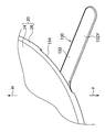
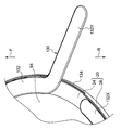
ここで、図6に示されるように、背面側分割ケース20は、真空断熱構造部70を有する。具体的には、背面側分割ケース20は、一対の内板72及び外板74によって形成される。内板72は、熱伝導性を有するアルミニウム等の金属板によって形成される。一方、外板74は、熱伝導性の有無を問わず、金属板、樹脂板、又はガラス等によって形成される。なお、内板72は、金属板等に限らず、樹脂板、又はガラス等によって形成されても良い。
一対の内板72及び外板74は、各々の中央部同士を対向させた状態で、各々の外周部同士が気密にろう接(ろう接合)される。これにより、一対の内板72の中央部と外板74の中央部との間に、密封された密封空間76が形成される。この密封空間76によって、内板72と外板74とが断熱される。また、密封空間76は、真空脱気される。これにより、密封空間76の断熱性能が高められる。なお、「ろう接」とは、溶接及びはんだ接合を含む概念である。
そして、背面側分割ケース20のうち、内板72、外板74、及び密封空間76の三層とされた部位が真空断熱構造部70とされる。真空断熱構造部70は、ケース12における表示器54と反対側に配置される。この真空断熱構造部70によって、背面側分割ケース20の底壁部24が構成される。また、真空断熱構造部70によって、底壁部24の対向部24Tが構成される。これにより、真空断熱構造部70の密封空間76によって、電子部品44から対向部24Tの外面24Rに伝達される熱が低減される。
次に、第1実施形態の作用について説明する。
本実施形態によれば、情報処理装置10は、電子部品44を収容するケース12を備える。ケース12は、背面側分割ケース20及び正面側分割ケース30を有する。背面側分割ケース20は、外面24Rが情報処理装置10の外部に露出される底壁部24を有する。この底壁部24の対向部24Tには、電子部品44が対向される。
ここで、図6に示されるように、電子部品44が発熱すると、背面側分割ケース20の底壁部24の温度が上昇し易くなる。特に、電子部品44と対向する底壁部24の対向部24Tの温度が上昇し易くなる。
これに対して本実施形態では、底壁部24の対向部24Tが真空断熱構造部70によって構成される。これにより、電子部品44から、対向部24Tの外面24Rに伝達される熱が、真空断熱構造部70の密封空間76によって断熱される。この結果、対向部24Tの外面24Rの温度上昇が抑制される。したがって、利用者が対向部24Tの外面24Rに触れたときに、利用者が感じる不快感が軽減される。
また、真空断熱構造部70は、背面側分割ケース20の底壁部24を構成する。これにより、本実施形態では、背面側分割ケース20の底壁部と電子部品44との間に、真空断熱材が配置される場合と比較して、ケース12を薄くすることができる。
このように本実施形態では、電子部品44から背面側分割ケース20の底壁部24の外面24Rに伝達される熱を低減しつつ、ケース12の薄型化を図ることができる。
また、底壁部24の対向部24Tは、利用者の手が触れ易い底壁部24の中央部に位置される。この対向部24Tは、前述したように、真空断熱構造部70によって構成される。これにより、利用者が感じる不快感を効果的に軽減することができる。
さらに、真空断熱構造部70は、底壁部24の対向部24Tだけでなく、底壁部24全体を構成する。これにより、底壁部24の外面24Rの温度上昇が、当該外面24Rの全面に亘って抑制される。したがって、利用者が感じる不快感がさらに軽減される。
しかも、真空断熱構造部70の内板72は、熱伝導性を有する金属板で形成される。これにより、図6に矢印aで示されるように、電子部品44から対向部24Tの内板72に伝達された熱は、当該内板72の全体に拡散して伝達される。したがって、対向部24Tの外面24Rの温度上昇がさらに抑制される。
また、真空断熱構造部70は、当該真空断熱構造部70の厚み方向から見て、円形状に形成される。これにより、密封空間76の真空脱気がされたときに、真空断熱構造部70の所定部に応力が集中することが抑制される。したがって、内板72及び外板74を薄くすることができるため、ケース12の薄型化を図ることができる。
次に、第1実施形態の変形例について説明する。
図7に示される変形例では、背面側分割ケース20の底壁部24の対向部24Tと電子部品44との間に、熱伝導部材80が設けられる。つまり、底壁部24の対向部24Tは、熱伝導部材80を間において電子部品44と対向する。
熱伝導部材(放熱部材)80は、例えば、熱伝導率が高い熱伝導ゴム、熱伝導グリス、又は熱伝導シートが用いられる。そして、電子部品44は、熱伝導部材80を介して対向部24Tの内板72に接触される。これにより、電子部品44の熱が、熱伝導部材80を介して底壁部24の内板72に伝達される。この結果、電子部品44から対向部24Tの内板72に伝達される熱の伝達効率が高められる。
ここで、内板72は、前述したように熱伝導性を有する。これにより、電子部品44から内板72に伝達された熱は、矢印aで示されるように、内板72の広範囲に拡散される。したがって、本変形例では、熱伝導部材80がない場合と比較して、底壁部24の対向部24Tの外面24Rの温度上昇がさらに抑制される。
(第2実施形態)
次に、第2実施形態について説明する。なお、第2実施形態において、第1実施形態と同じ構成の部材等には、同符号を付して説明を適宜省略する。
次に、第2実施形態について説明する。なお、第2実施形態において、第1実施形態と同じ構成の部材等には、同符号を付して説明を適宜省略する。
図8及び図9に示されるように、第2実施形態に係る情報処理装置90は、例えば、タブレット端末等の携帯端末とされる。この情報処理装置90は、扁平な直方体状に形成される。この情報処理装置90は、図10及び図11に示されるように、ケース92と、タッチパネルモジュール50と、背面側カバー110とを有する。
ケース92は、収容室94を内部に有する。また、ケース92は、当該ケース92の厚み方向(矢印S方向)に分割される背面側分割ケース20及び正面側分割ケース100を有する。背面側分割ケース20と正面側分割ケース100とは、互いに組み合われた状態で内部に収容室94を形成する。収容室94は、密閉された密閉室とされる。この収容室94には、バッテリ40、プリント基板42、及び電子部品44が収容される。
なお、図11に示されるように、本実施形態の電子部品44は、熱伝導部材80を介して背面側分割ケース20の底壁部24の内板72に接触される。また、本実施形態の背面側分割ケース20の側壁部26は、側壁側真空断熱構造部71を有する。側壁側真空断熱構造部71は、背面側分割ケース20の底壁部24を構成する真空断熱構造部70と同様に、内板72、外板74、及び密封空間76によって形成される。
正面側分割ケース100は、例えば、金属又は樹脂によって形成される。この正面側分割ケース100は、ケース本体部102と、連結部34とを有する。ケース本体部(正面側分割ケース本体部)102は、底壁部104と、側壁部106とを有する。底壁部104は、矩形状に形成される。また、底壁部104の正面側には、タッチパネルモジュール50が設けられる。このタッチパネルモジュール50のタッチパネル52は、矩形状に形成される。
また、底壁部104の中央部には、背面側分割ケース20側へ延出する連結部34が設けられる。連結部34の雄ネジ部36は、背面側分割ケース20の雌ネジ部28に締め込まれる。さらに、ケース本体部102の底壁部104は、背面側分割ケース20の側壁部26よりも外側へ張り出す。この底壁部104の外周部には、背面側へ延出する側壁部106が設けられる。
ここで、図10に示されるように、ケース92の正面側分割ケース100には、背面側カバー110が取り付けられる。背面側カバー110は、正面側が開口された箱状に形成される。この背面側カバー110は、底壁部112と、側壁部118とを有する。なお、背面側カバー110は、カバーの一例である。
底壁部112は、矩形状に形成される。この底壁部112の中央部には、露出開口114が形成される。露出開口114は、底壁部112を厚み方向に貫通する円形状の貫通孔とされる。この露出開口114には、背面側分割ケース20の底壁部24が配置される。これにより、露出開口114から背面側分割ケース20の底壁部24の外面24Rが露出される。
図11に示されるように、露出開口114に背面側分割ケース20の底壁部24が配置された状態では、背面側カバー110の底壁部112の外面112Rと、背面側分割ケース20の底壁部24の外面24Rとが面一とされる。すなわち、背面側カバー110の底壁部112の外面112Rと、真空断熱構造部70の外面とが面一とされる。
なお、ここいう「面一」とは、背面側分割ケース20及び背面側カバー110の製造誤差等によって、底壁部24の外面24Rと底壁部112の外面112Rとが僅かにずれた状態を含む概念である。
露出開口114の周縁部には、正面側へ延出されるリブ116が設けられる。リブ116は、筒状(円筒状)に形成される。このリブ116の内側には、背面側分割ケース20が嵌め込まれる。これにより、背面側カバー110に対する背面側分割ケース20の位置ずれが抑制される。
背面側カバー110の側壁部118は、底壁部112の外周部から正面側へ延出する。この側壁部118は、正面側分割ケース100の側壁部106に組み合わされた状態で接合される。これにより、背面側カバー110と正面側分割ケース100との間に、図示しないコネクタ及び配線等を収容する収容室111が形成される。
次に、第2実施形態の作用について説明する。
図11に示されるように、本実施形態によれば、ケース92は、内部に収容室94を有する。この収容室94には、電子部品44が収容される。
ここで、電子部品44が発熱すると、電子部品44によって加熱された収容室94内の空気が対流する。この加熱された空気が収容室94の外部に流出すると、例えば、収容室94の周辺の部品等が加熱される可能性がある。また、収容室94から流出した空気が、利用者の手等にあたると、利用者が不快感を受ける可能性がある。
これに対して本実施形態の収容室94は、密閉室とされる。これにより、電子部品44によって加熱された空気が、収容室94から外部に流出しない。したがって、電子部品44によって加熱された空気が、収容室94の周辺の部品及び利用者の手等に当たることが抑制される。したがって、収容室94の周辺の部品の温度上昇が抑制されるとともに、利用者が受ける不快感が軽減される。
また、本実施形態では、側壁側真空断熱構造部71によって背面側分割ケース20の側壁部26が構成される。これにより、矢印bで示されるように、収容室94から側壁部26の外周面26Aに伝達される電子部品44等の熱が、側壁側真空断熱構造部71の密封空間76によって断熱される。したがって、収容室94の周辺の部品の温度上昇がさらに抑制される。なお、側壁側真空断熱構造部71は、側壁部26の少なくとも一部を構成することができる。
さらに、本実施形態では、ケース92に背面側カバー110が取り付けられる。この背面側カバー110の底壁部112には、露出開口114が形成される。この露出開口114には、背面側分割ケース20の底壁部24が配置される。これにより、本実施形態では、背面側分割ケース20の底壁部24が背面側カバー110によって覆われる場合と比較して、情報処理装置90の薄型化を図ることができる。
しかも、背面側分割ケース20の底壁部24の外面24Rと背面側カバー110の底壁部112の外面112Rとは、面一とされる。これにより、情報処理装置90の薄型化を図りつつ、情報処理装置90の意匠性を高めることができる。
(第3実施形態)
次に、第3実施形態について説明する。なお、第3実施形態において、第1,第2実施形態と同じ構成の部材等には、同符号を付して説明を適宜省略する。
次に、第3実施形態について説明する。なお、第3実施形態において、第1,第2実施形態と同じ構成の部材等には、同符号を付して説明を適宜省略する。
図12に示されるように、第3実施形態に係る情報処理装置120は、背面側分割ケース20を冷却するヒートパイプ130及び冷却器136を備える。ヒートパイプ130は、内部が真空脱気された扁平なパイプ材132と、パイプ材132の内部に封入された図示しない作動液とを有する。なお、本実施形態では、バッテリ40が背面側分割ケース20の外の収容室11に収容される。また、図12では、背面側カバー110の図示が省略される。
図13に示されるように、パイプ材132は、蒸発部132X及び凝縮部132Yを有する。蒸発部132Xは、背面側分割ケース20の外周部に沿って円弧状に湾曲される。この蒸発部132Xによって、電子部品44が半周以上に亘って囲まれる。
図14に示されるように、蒸発部132Xは、背面側分割ケース20の内板72と熱交換可能にろう接される。これにより、内板72の熱によって、蒸発部132Xが加熱される。なお、本実施形態の蒸発部132Xは、ろう材133を介して内板72に接合される。また、本実施形態の背面側分割ケース20には、雌ネジ部28が設けられていない。この背面側分割ケース20は、例えば、正面側分割ケース100の連結部34にろう接される。
ここで、内板72の熱によって、蒸発部132X中の作動液が蒸発されると、内板72から蒸発潜熱が奪われる。これにより、内板72が冷却される。なお、蒸発部132Xで蒸発された作動液は、蒸発部132Xの一端側に接続された凝縮部132Y(図13参照)へ流れる。
一方、凝縮部132Yは、図15及び図16に示されるように、パイプ材132の一端部に設けられる。この凝縮部132Yは、背面側分割ケース20の側壁部26に形成された切欠き状の出入口134から収容室94の外部へ延出される。この凝縮部132Yは、冷却器136と対向される。
冷却器136は、正面側分割ケース100と背面側カバー110との間に形成された収容室111(図12参照)に収容される。この冷却器136は、例えば、冷却風を生成するファンとされる。この冷却器136の冷却風によって、凝縮部132Yが冷却されると、凝縮部132Y内の作動液が凝縮される。凝縮された作動液は、例えば、図示しないウィックを介して蒸発部132Xへ供給される。この凝縮された作動液が、蒸発部132Xにおいて蒸発されることにより、内板72が再び冷却される。このようにパイプ材132中の作動液が相変化を繰り返すことにより、内板72が継続的に冷却される。
なお、ヒートパイプ130の凝縮部132Yには、冷却効率を高める冷却フィン等が設けられても良い。
次に、第3実施形態の作用について説明する。
本実施形態によれば、情報処理装置120は、ヒートパイプ130を備える。ヒートパイプ130は、背面側分割ケース20の底壁部24を構成する内板72を冷却する。これにより、背面側分割ケース20の底壁部24の外面24Rの温度上昇が抑制される。
また、図13に矢印cで示されるように、電子部品44の熱は、当該電子部品44を中心として底壁部24の内板72(図14参照)に放射状に伝達される。これに対して本実施形態の蒸発部132Xは、電子部品44を半周以上に亘って囲む。これにより、底壁部24の内板72に放射状に伝達された熱を蒸発部132Xによって効率的に吸熱することができる。
ここで、例えば、ヒートパイプの蒸発部が底壁部24の中央部に配置されると、電子部品44の熱が、蒸発部で吸熱されずに当該蒸発部を越えて底壁部24の外周部へ伝達される可能性がある。これに対して本実施形態の蒸発部132Xは、底壁部24の外周部に沿って配置される。これにより、電子部品44から底壁部24に伝達された熱を蒸発部132Xによって効率的に吸熱することができる。
(第4実施形態)
次に、第4実施形態について説明する。なお、第4実施形態において、第1~第3実施形態と同じ構成の部材等には、同符号を付して説明を適宜省略する。
次に、第4実施形態について説明する。なお、第4実施形態において、第1~第3実施形態と同じ構成の部材等には、同符号を付して説明を適宜省略する。
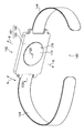
図17に示されるように、第4実施形態に係る情報処理装置140は、腕時計型のウェアラブル端末(スマートウォッチ)とされる。この情報処理装置140は、装置本体142と、一対のベルト144とを備える。
装置本体142は、ケース150を有する。ケース150は、当該ケース150の厚み方向に分割される背面側分割ケース151及びタッチパネルモジュール154を有する。なお、背面側分割ケース151は、第1分割ケースの一例である。また、タッチパネルモジュール154は、第2分割ケースの一例である。
図18及び図19に示されるように、背面側分割ケース151は、例えば、金属又は樹脂に形成される。また、背面側分割ケース151は、正面側に収容口152(図20参照)を有する箱状に形成される。この収容口152から背面側分割ケース151内の収容室156にプリント基板164等が収容される。また、背面側分割ケース151には、一対のベルト144が設けられる。一対のベルト144は、利用者の腕に巻き付けられる。
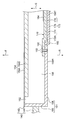
図20に示されるように、背面側分割ケース151の正面側には、タッチパネルモジュール154が取り付けられる。このタッチパネルモジュール154は、タッチパネル154Aと、表示器154Bとを有する。このタッチパネルモジュール154によって、背面側分割ケース151の収容口152が閉じられる。これにより、背面側分割ケース151の内部に収容室156が形成される。つまり、背面側分割ケース151及びタッチパネルモジュール154は、互いに組み合わされた状態で内部に収容室156を形成する。
図19に示されるように、収容室156には、プリント基板164及びバッテリ166が収容される。プリント基板164には、図示しない複数の電子部品が実装される。このプリント基板164及びバッテリ166は、後述する真空断熱構造体170の真空断熱構造部172に取り付けられる。
背面側分割ケース151は、底壁部158と、底壁部158の外周部から正面側へ延出する側壁部160とを有する。底壁部158は、矩形状に形成される。この底壁部158の中央部には、露出開口162が形成される。露出開口162は、底壁部158を厚み方向(矢印S方向)に貫通する円形状の貫通孔とされる。
露出開口162には、真空断熱構造体170が配置される。真空断熱構造体170は、真空断熱構造部172と、フランジ部180とを有する。図20に示されるように、真空断熱構造体170は、一対の内板174及び外板176によって形成される。
一対の内板174及び外板176は、各々の中央部同士を対向させた状態で、各々の外周部同士が気密にろう接(ろう接合)される。これにより、一対の内板174及び外板176の間に、密封された密封空間178が形成される。そして、真空断熱構造体170のうち、内板174、外板176、及び密封空間178の三層とされた部位が真空断熱構造部172とされる。また、真空断熱構造部172の外周部には、フランジ部180が設けられる。
真空断熱構造部172は、背面側分割ケース151の正面側から露出開口162内に配置される。そして、真空断熱構造部172の外面172Rは、露出開口162から情報処理装置140の外部に露出される。また、フランジ部180は、露出開口162の周縁部にビス182によって固定される。この真空断熱構造体170によって、露出開口162が閉じられる。
ここで、真空断熱構造体170の真空断熱構造部172は、背面側分割ケース151の底壁部158の対向部158Tを構成する。また、真空断熱構造部172の外面172Rは、背面側分割ケース151の底壁部158の外面を形成する。なお、対向部158Tには、プリント基板164に実装された電子部品が対向される。また、背面側分割ケース151の底壁部158は、ケースの壁部の一例である。
真空断熱構造部172は、底壁部158の外面158Rよりも外側へ突出される。また、真空断熱構造部172の外面172Rが、底壁部158の外面158Rよりも外側に位置する。これにより、本実施形態では、真空断熱構造部172の外面172Rと底壁部158の外面158Rとが面一の場合と比較して、収容室156が広くなる。
次に、第4実施形態の作用について説明する。
図20に示されるように、本実施形態によれば、背面側分割ケース151の底壁部158の対向部158Tは、真空断熱構造体170の真空断熱構造部172によって構成される。これにより、プリント基板164に実装された電子部品から、対向部158Tの外面172Rに伝達される熱が、真空断熱構造部172の密封空間178によって断熱される。この結果、対向部158Tの外面172Rの温度上昇が抑制される。したがって、例えば、利用者の腕が、対向部158Tの外面172Rに触れたときに、利用者が感じる不快感が軽減される。
また、本実施形態では、真空断熱構造部172によって、底壁部158の対向部158Tが構成される。つまり、真空断熱構造部172によって、背面側分割ケース151の底壁部158の一部が形成される。これにより、本実施形態では、背面側分割ケース151の底壁部とプリント基板164との間に真空断熱材が配置される場合と比較して、背面側分割ケース151を薄くすることができる。
このように本実施形態では、プリント基板164に実装された電子部品から底壁部158の対向部158Tの外面172Rに伝達される熱を低減しつつ、背面側分割ケース151の薄型化を図ることができる。
また、本実施形態では、対向部158Tの外面172Rが、底壁部158の外面158Rよりも外側に位置する。これにより、本実施形態では、対向部158Tの外面172Rと底壁部158の外面158Rとが面一の場合と比較して、収容室156を広くすることができる。
一方、底壁部158の対向部158Tの外面172Rが、底壁部158の外面158Rよりも外側に位置する場合、利用者の腕が対向部158Tの外面172Rに接触し易くなる。この場合、対向部158Tの外面172Rの温度が高いと、利用者に不快感を与える可能性がある。
これに対して本実施形態の対向部158Tは、前述したように、真空断熱構造部172によって構成される。これにより、対向部158Tの外面172Rの温度上昇が抑制される。したがって、利用者の腕が、対向部158Tの外面172Rに触れたときに、利用者が感じる不快感が軽減される。
次に、上記第1~第4実施形態の変形例について説明する。なお、以下の説明では、第1実施形態を例に各種の変形例について説明するが、これらの変形例は、第2~第4実施形態にも適宜適用可能である。
上記第1実施形態において、真空断熱構造部70の内板72の内面は、例えば、鏡面処理(鏡面仕上げ)されても良い。この場合、電子部品44から放射される放射熱が内板72の内面によって反射される。したがって、真空断熱構造部70の断熱性能がさらに向上する。なお、内板72の内面に限らず、外板74の内面が鏡面処理されても良い。また、例えば、密封空間76に、電子部品44の放射熱を反射する銅箔等の反射部材が設けられても良い。
また、上記第1実施形態では、背面側分割ケース20の底壁部24の全体が真空断熱構造部70によって構成される。しかし、背面側分割ケース20の底壁部24の対向部24Tのみが真空断熱構造部70によって構成されても良い。つまり、背面側分割ケース20の底壁部24のうち、少なくとも対向部24Tを真空断熱構造部70によって構成することができる。
また、上記第1実施形態では、真空断熱構造部70が当該真空断熱構造部70の厚み方向から見て円形状を成す。しかし、真空断熱構造部の形状は、適宜変更可能であり、例えば、真空断熱構造部を厚み方向から見て矩形状を成しても良い。
また、上記実施形態のケース12は、背面側分割ケース20及び正面側分割ケース30によって形成されるが、ケース12の構造は、適宜変更可能である。
また、上記第1実施形態に係る情報処理装置10は、タッチパネルモジュール50を備える。しかし、タッチパネルモジュール50は、省略されても良い。
また、上記第1実施形態に係る情報処理装置10は、タブレット端末とされる。しかし、上記第1実施形態は、発熱する電子部品を収容する種々のケースに適用可能である。
以上、本願が開示する技術の一実施形態について説明したが、本願が開示する技術は上記の実施形態に限定されるものでない。また、上記実施形態及び各種の変形例を適宜組み合わせて用いても良いし、本願が開示する技術の要旨を逸脱しない範囲において、種々なる態様で実施し得ることは勿論である。
Claims (20)
- 電子部品と、
外面が外部に露出するとともに前記電子部品と対向する真空断熱構造部を有し、前記電子部品を収容するケースと、
を備える情報処理装置。 - 前記ケースは、外面が外部に露出する壁部を有し、
前記真空断熱構造部は、前記壁部のうち、前記電子部品と対向する部位を少なくとも構成する、
請求項1に記載の情報処理装置。 - 前記真空断熱構造部の前記外面を露出させる露出開口を有し、前記ケースに取り付けられるカバーを備える、
請求項1又は請求項2に記載の情報処理装置。 - 前記真空断熱構造部の前記外面は、前記カバーの外面と面一とされる、
請求項3に記載の情報処理装置。 - 前記壁部は、前記真空断熱構造部の外面を外部に露出させる露出開口を有する、
請求項2に記載の情報処理装置。 - 前記真空断熱構造部の前記外面は、前記壁部の外面よりも外側に位置する、
請求項5に記載の情報処理装置。 - 前記ケースは、互いに組み合わされた状態で内部に前記電子部品を収容する第1分割ケース及び第2分割ケースを有し、
前記壁部は、前記第1分割ケースに設けられる、
請求項2,5,6の何れか1項に記載の情報処理装置。 - 前記第1分割ケースは、前記電子部品を収容する収容口と、前記収容口側の内周面に設けられた雌ネジ部と、を有し、
前記第2分割ケースは、前記雌ネジ部に締め込まれる雄ネジ部を有する、
請求項7に記載の情報処理装置。 - 前記第1分割ケースは、
前記壁部としての底壁部と、
前記底壁部の外周部から前記第2分割ケース側へ延出し、前記電子部品を囲む側壁部と、
を有し、
前記側壁部は、側壁側真空断熱構造部を有する、
請求項7又は請求項8に記載の情報処理装置。 - 前記ケースは、内部に前記電子部品を収容する密閉室を有する、
請求項1~請求項9の何れか1項に記載の情報処理装置。 - 前記電子部品は、熱伝導部材を介して前記真空断熱構造部に接触される、
請求項1~請求項10の何れか1項に記載の情報処理装置。 - 前記真空断熱構造部に設けられるヒートパイプと、
ヒートパイプを冷却する冷却器と、
を備える、
請求項1~請求項11の何れか1項に記載の情報処理装置。 - 前記ヒートパイプは、前記電子部品を囲む、
請求項12に記載の情報処理装置。 - 前記ヒートパイプは、前記真空断熱構造部の外周部に沿って配置される、
請求項12又は請求項13に記載の情報処理装置。 - 前記ヒートパイプの一端部は、前記真空断熱構造部の外側へ延出され、
前記冷却器は、前記ヒートパイプの前記一端部を冷却する、
請求項12~請求項14の何れか1項に記載の情報処理装置。 - 前記真空断熱構造部は、該真空断熱構造部を厚み方向から見て、円形状を成す、
請求項1~請求項15の何れか1項に記載の情報処理装置。 - 前記真空断熱構造部は、互いの間に密封空間を有する一対の内板及び外板を有する、
請求項1~請求項16の何れか1項に記載の情報処理装置。 - 前記内板は、熱伝導性を有する、
請求項17に記載の情報処理装置。 - 前記ケースに設けられる表示器を備え、
前記真空断熱構造部は、前記ケースにおける前記表示器と反対側に配置される、
請求項1~請求項18の何れか1項に記載の情報処理装置。 - 外面が外部に露出すると共に電子部品と対向する真空断熱構造部を有し、前記電子部品を収容する、
ケース。
Priority Applications (1)
| Application Number | Priority Date | Filing Date | Title |
|---|---|---|---|
| PCT/JP2016/064354 WO2017195364A1 (ja) | 2016-05-13 | 2016-05-13 | 情報処理装置及びケース |
Applications Claiming Priority (1)
| Application Number | Priority Date | Filing Date | Title |
|---|---|---|---|
| PCT/JP2016/064354 WO2017195364A1 (ja) | 2016-05-13 | 2016-05-13 | 情報処理装置及びケース |
Publications (1)
| Publication Number | Publication Date |
|---|---|
| WO2017195364A1 true WO2017195364A1 (ja) | 2017-11-16 |
Family
ID=60266935
Family Applications (1)
| Application Number | Title | Priority Date | Filing Date |
|---|---|---|---|
| PCT/JP2016/064354 Ceased WO2017195364A1 (ja) | 2016-05-13 | 2016-05-13 | 情報処理装置及びケース |
Country Status (1)
| Country | Link |
|---|---|
| WO (1) | WO2017195364A1 (ja) |
Citations (4)
| Publication number | Priority date | Publication date | Assignee | Title |
|---|---|---|---|---|
| JPH11224990A (ja) * | 1998-02-04 | 1999-08-17 | Fujitsu Ltd | 電子機器 |
| JP2000106495A (ja) * | 1998-09-29 | 2000-04-11 | Kitagawa Ind Co Ltd | 電気電子器具の内部構造 |
| JP2001350546A (ja) * | 2000-06-06 | 2001-12-21 | Matsushita Refrig Co Ltd | ノート型コンピュータ |
| JP2008270414A (ja) * | 2007-04-18 | 2008-11-06 | Jatco Ltd | コントロールユニット |
-
2016
- 2016-05-13 WO PCT/JP2016/064354 patent/WO2017195364A1/ja not_active Ceased
Patent Citations (4)
| Publication number | Priority date | Publication date | Assignee | Title |
|---|---|---|---|---|
| JPH11224990A (ja) * | 1998-02-04 | 1999-08-17 | Fujitsu Ltd | 電子機器 |
| JP2000106495A (ja) * | 1998-09-29 | 2000-04-11 | Kitagawa Ind Co Ltd | 電気電子器具の内部構造 |
| JP2001350546A (ja) * | 2000-06-06 | 2001-12-21 | Matsushita Refrig Co Ltd | ノート型コンピュータ |
| JP2008270414A (ja) * | 2007-04-18 | 2008-11-06 | Jatco Ltd | コントロールユニット |
Similar Documents
| Publication | Publication Date | Title |
|---|---|---|
| US9625215B2 (en) | Electronic device and heat dissipation plate | |
| US7742295B2 (en) | Cooling device and electronic device | |
| CN105723821A (zh) | 便携式电子设备的冷却构造 | |
| CN107006136B (zh) | 散热机构及具有该散热机构的电子调速器、电子装置 | |
| CN113934277A (zh) | 电子设备以及冷却模块 | |
| TWI514122B (zh) | 電子裝置與散熱板 | |
| US20080019093A1 (en) | Electronic device | |
| US11839055B2 (en) | Heat-conducting assembly and terminal | |
| JP2017046215A (ja) | 電子機器 | |
| JP2015130440A (ja) | 電子機器 | |
| JP2008131512A (ja) | 携帯端末装置 | |
| JP2017188601A (ja) | 電子機器 | |
| WO2003043397A1 (fr) | Appareil electronique | |
| JP2009053856A (ja) | 電子機器 | |
| JP6649854B2 (ja) | 電子機器 | |
| JP2019020557A (ja) | 撮像装置 | |
| US9277676B2 (en) | Electronic apparatus | |
| CN112640597A (zh) | 柔性电子装置 | |
| WO2014077081A1 (ja) | ヒートパイプ、スマートフォン、タブレット端末または携帯情報端末 | |
| JP2007150192A (ja) | ヒートパイプを有した放熱器を備える情報処理装置 | |
| CN209861402U (zh) | 柔性电子装置 | |
| JP2008299628A (ja) | 電子機器、および冷却ユニット | |
| WO2017195364A1 (ja) | 情報処理装置及びケース | |
| JP6473920B2 (ja) | 電子機器 | |
| JPH09293985A (ja) | 電子機器 |
Legal Events
| Date | Code | Title | Description |
|---|---|---|---|
| NENP | Non-entry into the national phase |
Ref country code: DE |
|
| 121 | Ep: the epo has been informed by wipo that ep was designated in this application |
Ref document number: 16901712 Country of ref document: EP Kind code of ref document: A1 |
|
| 122 | Ep: pct application non-entry in european phase |
Ref document number: 16901712 Country of ref document: EP Kind code of ref document: A1 |
|
| NENP | Non-entry into the national phase |
Ref country code: JP |