WO2017191760A1 - ナイロン6粒子の製造方法および立体造形物の製造方法 - Google Patents
ナイロン6粒子の製造方法および立体造形物の製造方法 Download PDFInfo
- Publication number
- WO2017191760A1 WO2017191760A1 PCT/JP2017/015833 JP2017015833W WO2017191760A1 WO 2017191760 A1 WO2017191760 A1 WO 2017191760A1 JP 2017015833 W JP2017015833 W JP 2017015833W WO 2017191760 A1 WO2017191760 A1 WO 2017191760A1
- Authority
- WO
- WIPO (PCT)
- Prior art keywords
- nylon
- particles
- solution
- less
- manufacturing
- Prior art date
- Legal status (The legal status is an assumption and is not a legal conclusion. Google has not performed a legal analysis and makes no representation as to the accuracy of the status listed.)
- Ceased
Links
Images


Classifications
-
- B—PERFORMING OPERATIONS; TRANSPORTING
- B29—WORKING OF PLASTICS; WORKING OF SUBSTANCES IN A PLASTIC STATE IN GENERAL
- B29C—SHAPING OR JOINING OF PLASTICS; SHAPING OF MATERIAL IN A PLASTIC STATE, NOT OTHERWISE PROVIDED FOR; AFTER-TREATMENT OF THE SHAPED PRODUCTS, e.g. REPAIRING
- B29C67/00—Shaping techniques not covered by groups B29C39/00 - B29C65/00, B29C70/00 or B29C73/00
-
- B—PERFORMING OPERATIONS; TRANSPORTING
- B33—ADDITIVE MANUFACTURING TECHNOLOGY
- B33Y—ADDITIVE MANUFACTURING, i.e. MANUFACTURING OF THREE-DIMENSIONAL [3D] OBJECTS BY ADDITIVE DEPOSITION, ADDITIVE AGGLOMERATION OR ADDITIVE LAYERING, e.g. BY 3D PRINTING, STEREOLITHOGRAPHY OR SELECTIVE LASER SINTERING
- B33Y10/00—Processes of additive manufacturing
-
- C—CHEMISTRY; METALLURGY
- C08—ORGANIC MACROMOLECULAR COMPOUNDS; THEIR PREPARATION OR CHEMICAL WORKING-UP; COMPOSITIONS BASED THEREON
- C08J—WORKING-UP; GENERAL PROCESSES OF COMPOUNDING; AFTER-TREATMENT NOT COVERED BY SUBCLASSES C08B, C08C, C08F, C08G or C08H
- C08J3/00—Processes of treating or compounding macromolecular substances
- C08J3/12—Powdering or granulating
- C08J3/14—Powdering or granulating by precipitation from solutions
Definitions
- the present invention relates to a method for producing nylon 6 particles and a method for producing a three-dimensional structure.
- nylon 6 particles As a method for producing particles containing nylon 6 as a main component (hereinafter also simply referred to as “nylon 6 particles”) having a particle diameter of about several ⁇ m to several tens of ⁇ m, a solution in which nylon 6 is heated and dissolved is cooled. There is known a method of precipitating nylon 6 and agglomerating it into particles. According to this method, the precipitated nylon 6 is agglomerated by surface tension. Therefore, a shape closer to a true sphere is formed than the method of physically pulverizing nylon 6 with a ball mill or the like to produce particles having the above particle diameter. It is possible to obtain particles having the same.
- Patent Document 1 when a solution in which nylon 6, calcium chloride and ethylene glycol are mixed and heated to dissolve nylon 6 is cooled, nylon 6 particles having a shape closer to a true sphere and having a narrower particle size distribution Is supposed to be obtained. Patent Document 1 describes that it is preferable to rapidly cool the solution. In the example of Patent Document 1, after the solution containing nylon 6 is allowed to cool to 120 ° C., the contents of the solution are trayed. And rapidly cooled to produce nylon 6 particles.
- Patent Document 2 a polyamide is dissolved in a phenol, and a non-solvent of the polyamide and water are mixed to form a uniform solution, and then a polymer is precipitated to produce particles such as polyamide 6. Yes.
- nylon 6 particles have a wide range of applications such as paints, cosmetic bases, additives such as lubricants and cutting oils. Moreover, nylon 6 particle
- grains can also be used as a material for manufacture of the three-dimensional molded item by a powder bed melt-bonding method.
- the powder bed melt bonding method is one of methods for producing a three-dimensional structure.
- a powder material containing particles containing resin material or metal material is laid flat to form a thin film, and a laser is irradiated to a desired position on the thin film to select particles contained in the powder material.
- Sintered or melted and bonded hereinafter, the bonding of particles by sintering or melting is also simply referred to as “melt bonding”
- melt bonding thereby finely dividing the three-dimensional object in the thickness direction (hereinafter referred to as “melt bonding”) , Simply referred to as “modeled object layer”).
- a powder material is further spread on the layer thus formed, and laser irradiation is performed to selectively melt bond the particles contained in the powder material, thereby forming the next modeled object layer.
- laser irradiation is performed to selectively melt bond the particles contained in the powder material, thereby forming the next modeled object layer.
- nylon 6 is dissolved in ethylene glycol in the presence of calcium chloride and then allowed to cool to 120 ° C., and then the contents of the solution are transferred to a tray and rapidly cooled to form a shape closer to a true sphere. Nylon 6 particles having a more uniform particle diameter are obtained. However, even if nylon 6 particles are produced based on the method described in Patent Document 1, it is difficult to obtain particles having a shape close to a true sphere, and it is difficult to sufficiently narrow the particle size distribution. is there. In particular, it has been found that many nylon 6 particles obtained by the method described in Patent Document 1 are cracked or partially chipped.
- nylon 6 particles having a shape closer to a true sphere and having a narrower particle size distribution are preferably used.
- the shape of the particles used for three-dimensional modeling such as the powder bed fusion bonding method is greatly deviated from the true sphere or the particle size distribution is wide, gaps or the like are likely to occur between the particles when the powder material is spread.
- the gap is generated, the modeling accuracy of the three-dimensional model is difficult to increase, and a defect derived from the gap is generated in the three-dimensional model, so that the mechanical strength of the three-dimensional model is also difficult to increase.
- the present invention relates to the following nylon 6 particle manufacturing method and three-dimensional model manufacturing method.
- Cooling rate of a solution obtained by mixing nylon 6, inorganic salt and polyhydric alcohol with heating, in which the nylon 6 is dissolved in the polyhydric alcohol, is 5 ° C./min to 10 ° C./min
- a step of forming a thin layer of a powder material containing nylon 6 particles produced by the production method according to any one of [1] to [8], and laser light is selectively applied to the formed thin layer And forming a shaped article layer formed by sintering or melt-bonding nylon 6 particles contained in the powder material; forming the thin layer; and forming the shaped article layer; Are repeated in this order a plurality of times, and the step of laminating the shaped article layer is included.
- the shape of the obtained particles can be made close to a true sphere, and the particle size distribution can be narrowed, and the method for producing nylon 6 particles, and the three-dimensional modeling using the nylon 6 particles produced by the above production method
- the manufacturing method of a thing, and the three-dimensional modeling apparatus which can manufacture a three-dimensional molded item using the nylon 6 particle manufactured by the said manufacturing method are provided.
- FIG. 1 is a flowchart showing a method for producing nylon 6 particles according to an embodiment of the present invention.
- FIG. 2 is an image obtained by imaging nylon 6 particles obtained in one embodiment of the present invention with a scanning electron microscope (SEM) at a magnification of 5000 times.
- FIG. 3 is an image obtained by imaging nylon 6 particles produced in the same manner as in the above-described embodiment of the present invention except that no inorganic salt is used, with a SEM at a magnification of 1000 times.
- FIG. 4 is an image obtained by imaging nylon 6 particles produced in the same manner as in the above-described embodiment of the present invention at a magnification of 5000 times with a SEM except that the cooling rate was increased from 10 ° C./min from the middle.
- FIG. 5 is a side view schematically showing the configuration of the three-dimensional modeling apparatus in one embodiment of the present invention.
- FIG. 6 is a diagram showing the main part of the control system of the three-dimensional modeling apparatus in one embodiment of the present invention.
- the nylon 6 particles are likely to be distorted, and the resulting nylon 6 particles are likely to be cracked or partially chipped, resulting in fine powder. Therefore, it is thought that the particle size distribution is widened.
- Patent Document 2 it is proposed to obtain polyamide particles by dissolving a polyamide in phenols, mixing a non-solvent of polyamide and water to form a uniform solution, and then precipitating the polymer. Yes.
- the polyamide particles obtained by this method tend to be excessively porous on the surface, and the particle size distribution is not sufficiently narrow, making it difficult to obtain particles suitable for three-dimensional modeling such as powder bed fusion bonding. .
- Use of phenols as a solvent is not preferable from the viewpoint of safety.
- the shape of the nylon 6 particles can be made closer to a sphere and the particle size distribution can be made narrower while using a safer polyhydric alcohol as a solvent.
- One embodiment of the present invention based on the above knowledge includes a step of cooling a nylon 6 solution while maintaining a cooling rate at 5 ° C./min to 10 ° C./min. It relates to the manufacturing method.
- a step of preparing a nylon 6 solution step S101
- a step of cooling the nylon 6 solution step S102
- a step of recovering nylon 6 particles step S103
- Step S101 The nylon 6 solution can be prepared by mixing nylon 6, an inorganic salt and a polyhydric alcohol while heating.
- dissolves means that nylon 6 will be in the state which cannot be visually confirmed as a result of heating more than the minimum of the heating temperature mentioned later.
- the polyhydric alcohol is not particularly limited as long as it is liquid at room temperature and can sufficiently dissolve nylon 6 by heating. Since the nylon 6 particles dissolve in the solvent at a temperature lower than the melting point of nylon 6 (225 ° C.) in the heated solvent, the polyhydric alcohol has a temperature of 50 ° C. lower than the melting point of nylon 6. It is preferable to use one having a boiling point.
- Examples of such polyhydric alcohols include ethylene glycol, triethylene glycol, propylene glycol, dipropylene glycol, 1,3-butylene glycol and 1,5-pentanediol.
- dipropylene glycol and 1,5-pentanediol having a boiling point higher than that of nylon 6 are preferable from the viewpoint of making nylon 6 easier to dissolve by heating.
- the polyhydric alcohol may be used alone or in combination of two or more. When two types of polyhydric alcohols are used in combination, the boiling point of the polyhydric alcohol having the lowest boiling point contained in the nylon 6 solution is preferably higher than the melting point of the nylon 6.
- the concentration of the aromatic alcohol in the nylon 6 solution is preferably 10% by mass or less with respect to the total mass of the nylon 6 solution, and is 5% by mass or less. More preferably, it is even more preferable that it is not substantially contained.
- the aromatic alcohol include compounds of cresols and phenols.
- the above inorganic salt promotes dissolution of nylon 6. Moreover, the said inorganic salt can adjust the precipitation speed
- the inorganic salt include a salt of at least one element selected from alkali metals and alkaline earth metals and acids such as hydrochloric acid, sulfuric acid, nitric acid, acetic acid, and carbonic acid.
- the inorganic salt includes a salt of at least one selected from lithium, sodium, potassium and calcium and the acid, specifically, calcium chloride, lithium chloride, lithium bromide, iodide. Examples include potassium, sodium bromide, sodium acetate, and calcium bromide. Of these, calcium chloride and lithium chloride are preferable from the viewpoint of improving handling properties.
- the inorganic salt may be used alone or in combination of two or more.
- the concentration of the inorganic salt is preferably 0.010% by mass to 7.5% by mass with respect to the total mass of the nylon 6 solution.
- concentration of the inorganic salt is 0.010% by mass or more, nylon 6 can be sufficiently dissolved in the polyhydric alcohol.
- concentration of the inorganic salt is 0.010% by mass or more, since nylon 6 is more uniformly precipitated by cooling, the shape of the obtained nylon 6 particles is close to a true sphere, and the obtained nylon 6 It is thought that the particle size distribution of the particles becomes narrow.
- the concentration of the inorganic salt is higher than 7.5% by mass, the effect of adjusting the volume average particle size and shape of the obtained nylon 6 particles is not so great, whereas the concentration of the inorganic salt becomes excessive. As a result, the properties of the obtained nylon 6 particles are likely to change.
- the volume average particle diameter of nylon 6 particles can be adjusted to a desired range by changing the concentration of inorganic salt in the above range, the concentration of inorganic salt is the volume of nylon 6 particles to be obtained. What is necessary is just to determine according to an average particle diameter.
- the concentration of the inorganic salt is 0.050 mass% or more and 7.5 mass% or less with respect to the total mass of the nylon 6 solution. It is preferable that it is 1.0 mass% or more and 7.5 mass% or less, and it is further more preferable that it is 2.0 mass% or more and 7.5 mass% or less.
- the concentration of the nylon 6 is preferably 1.0% by mass to 30% by mass with respect to the total mass of the nylon 6 solution.
- concentration of the nylon 6 is 1.0% by mass or more, the precipitated nylon 6 is deposited close to each other, so that the nylon 6 is sufficiently aggregated to form nylon 6 particles.
- concentration of the nylon 6 is 30% by mass or less, an appropriate amount of nylon 6 is precipitated and appropriately aggregated, so that the shape of the obtained nylon 6 particles is close to a true sphere, and the obtained particles It is thought that the particle size distribution becomes narrow.
- the concentration of nylon 6 is 1.0% by mass or more and 30% by mass or less with respect to the total mass of the nylon 6 solution. It is preferably 3.0% by mass or more and 20% by mass or less, more preferably 5% by mass or more and 20% by mass or less, and further preferably 10% by mass or more and 20% by mass or less. .
- the temperature of the heated nylon 6 solution may be a temperature at which nylon 6 is dissolved in the polyhydric alcohol, and may be 170 ° C. or higher and 300 ° C. or lower, for example. it can.
- the heating temperature is preferably lower than the boiling point of the polyhydric alcohol.
- the heating temperature may be lower than the melting point of nylon 6 (225 ° C.) as long as nylon 6 is dissolved.
- the heating temperature is a temperature equal to or higher than the melting point of nylon 6. It is preferable.
- heating is preferably performed while mixing.
- this process is not limited to the preparation of the nylon 6 solution according to the above procedure, and the nylon 6 solution may be prepared by other methods. You may use for this process.
- Step S102 Step of cooling the nylon 6 solution
- the nylon 6 solution is cooled to a temperature not higher than the glass transition temperature of nylon 6 while maintaining the cooling rate at 5 ° C./min or more and 10 ° C./min or less.
- the shape of the obtained nylon 6 particles becomes close to a true sphere, and the particle size distribution of the obtained particles becomes narrow.
- the heat distribution in the cooling nylon 6 solution is less likely to be biased, and the entire nylon 6 solution is cooled uniformly, so that the temperature distribution of the precipitated nylon 6 becomes more uniform and the surface tension is more uniform. This is thought to be due to the uniform distribution.
- the cooling rate is faster than 10 ° C./min, the temperature distribution of the nylon 6 solution is uneven, the surface tension of the precipitated nylon 6 is uneven, and the precipitated nylon 6 is less likely to aggregate more uniformly.
- the obtained nylon 6 particles are less likely to have a uniform particle diameter, and the nylon particles 6 are less likely to be spherical. If the cooling rate is faster than 10 ° C./min, the above temperature distribution remains in the agglomerated nylon 6 particles, and the nylon 6 particles are easily distorted, and the resulting nylon 6 particles are cracked or partially chipped. Is likely to occur. If the cooling rate is slower than 5 ° C./min, the spherically aggregated nylon 6 particles may further aggregate.
- the cooling rate can be controlled by known means. From the viewpoint of facilitating the control of the cooling rate, it is preferable to cool the nylon 6 solution in a sealed container filled with an inert gas such as nitrogen gas or argon gas.
- an inert gas such as nitrogen gas or argon gas.
- the cooling rate can be set to the above range by leaving it to stand in a room temperature environment and allowing to cool. .
- the cooling rate can be controlled to 5 ° C./min or more by increasing the concentration of the inert gas, for example.
- the cooling rate may be further reduced.
- water is put around the container containing the nylon 6 solution.
- the cooling rate can be controlled to 5 ° C./min or more by adjusting the external temperature by a method such as circulating the temperature.
- the nylon 6 particles are sufficiently solidified by maintaining the above cooling rate to a temperature equal to or lower than the glass transition temperature (50 ° C.) of nylon 6, the nylon 6 particles are collapsed or deformed. It is thought that it becomes harder to occur. From the viewpoint of solidifying the nylon 6 particles more sufficiently to make them less likely to collapse or deform, it is preferable to cool the nylon 6 solution to 45 ° C, and more preferably to 35 ° C. Further, from the viewpoint of facilitating the subsequent recovery process and the like, it is preferable to cool the nylon 6 solution to room temperature.
- cooling is performed with the nylon 6 It is preferably performed while mixing the solution.
- the stirring speed at this time is preferably 100 rpm or more and 1000 rpm or less, more preferably 150 rpm or more and 750 rpm or less, and further preferably 200 rpm or more and 600 rpm or less.
- the viscosity of a polyhydric alcohol becomes so high that the temperature of nylon 6 solution becomes low, you may raise a stirring speed in the process of cooling nylon 6 solution.
- Step S103 After cooling to the room temperature, the obtained nylon 6 particles may be recovered.
- Nylon 6 particles can be recovered by a known method such as filtration.
- FIG. 2 shows an image obtained by imaging nylon 6 particles obtained in the present embodiment with a scanning electron microscope (SEM).
- FIG. 2 is obtained by cooling a nylon 6 solution prepared by using the above polyhydric alcohol as dipropylene glycol and the above inorganic salt as calcium chloride to room temperature while maintaining the cooling rate at 5 ° C./min to 10 ° C./min. It is a SEM image of the obtained nylon 6 particles.
- FIG. 2 is an SEM image of nylon 6 particles produced with the inorganic salt concentration of 5.7% by mass taken at a magnification of 5000 times.
- the nylon 6 particles obtained in this embodiment have a shape closer to a true sphere.
- the nylon 6 particles obtained in this embodiment also have a narrower particle size distribution.
- the higher the concentration of the inorganic salt to be added the smaller the volume average particle diameter of the obtained nylon 6 particles, and nylon particles having a shape closer to a true sphere can be obtained.
- FIG. 3 shows that the polyhydric alcohol is dipropylene glycol and the nylon 6 solution prepared without using the inorganic salt is kept at room temperature while maintaining the cooling rate at 5 ° C./min to 10 ° C./min.
- It is the SEM image which imaged nylon 6 particle obtained by cooling to 1000 times magnification.
- FIG. 4 is an SEM image obtained by imaging nylon 6 particles produced by quenching after cooling to 120 ° C. by the method described in Example 1 of Patent Document 1 at a magnification of 5000 times.
- volume average particle diameter, particle size distribution, and shape The volume average particle diameter of the nylon 6 particles obtained in the present embodiment can be adjusted to a desired level by changing the concentration of the inorganic salt.
- the volume average particle diameter can be selected according to the use of nylon 6 particles. For example, when a material for producing a three-dimensional structure by the powder bed fusion bonding method is used, the volume average particle diameter is 12 ⁇ m. It is preferably 60 ⁇ m or less, preferably 15 ⁇ m or more and 55 ⁇ m or less, more preferably 15 ⁇ m or more and 50 ⁇ m or less, and further preferably 20 ⁇ m or more and 50 ⁇ m or less.
- the ratio of the volume average particle diameter to the number average particle diameter is 1.00 or more and 1.20.
- Nylon 6 particles can be produced.
- the ratio can be adjusted to a desired level by changing the concentration of inorganic salt, the cooling rate, and the like.
- the ratio is preferably 1.00 or more and 1.18 or less, more preferably 1.00 or more and 1.15 or less, and further preferably 1.00 or more and 1.10 or less.
- the volume average particle diameter and the number average particle diameter of nylon 6 particles are the volume average particle diameter and the number measured by a laser diffraction / scattering particle size distribution measuring device (for example, Microtrac MT3000II manufactured by Microtrac Bell Co., Ltd.).
- the average particle diameter can be set.
- the average of the ratio of the major axis to the minor axis (major axis / minor axis) (hereinafter simply referred to as “sphericity”) is an index showing how close the shape of the nylon 6 particles obtained in this embodiment is to a true sphere.
- the sphericity is preferably 1.00 or more and 1.15 or less, preferably 1.00 or more and 1.12 or less, and more preferably 1.00 or more and 1.10 or less. More preferably, it is 1.00 or more and 1.05 or less.
- nylon 6 particles obtained in this embodiment can be used for materials for three-dimensional modeling, paints, cosmetic bases, additives such as lubricating oil and cutting oil.
- the nylon 6 particles obtained in the present embodiment are particularly easy to handle when used as a material for three-dimensional modeling by the powder bed melt bonding method.
- the gap between the particles generated when laid down can be made smaller than that of the conventional nylon 6 particles, a three-dimensional object having higher modeling accuracy and higher mechanical strength is manufactured. be able to.
- the manufacturing method of a three-dimensional molded item This embodiment concerns on the manufacturing method of the three-dimensional molded item using the nylon 6 particle manufactured by the said method.
- the method according to the present embodiment can be performed in the same manner as the ordinary powder bed fusion bonding method except that the powder material containing nylon 6 particles produced by the above method is used.
- the method according to this embodiment includes (2-1) a step of forming a thin layer of a powder material containing nylon 6 particles produced by the above method, and (2-2) A step of selectively irradiating a laser beam to form a shaped article layer formed by sintering or melt-bonding nylon 6 particles contained in the powder material; (2-3) step (2-1) and step (2-2) is repeated a plurality of times in this order, and the molded object layer is laminated.
- step (2-2) one of the three-dimensional object layers constituting the three-dimensional object is formed, and by further repeating the steps (2-1) and (2-2) in the step (2-3), The next layer of the three-dimensional structure is laminated, and the final three-dimensional structure is manufactured.
- the thickness of the thin layer can be set according to the thickness of the modeled object layer. Although the thickness of a thin layer can be arbitrarily set according to the precision of the three-dimensional molded item to manufacture, it is 0.01 mm or more and 0.30 mm or less normally. By making the thickness of the thin layer 0.01 mm or more, the nylon 6 particles of the lower layer are melt-bonded by the laser irradiation for forming the next layer, or the modeling layer of the lower layer is remelted Can be prevented. By setting the thickness of the thin layer to 0.30 mm or less, the energy of the laser is conducted to the lower part of the thin layer, and the nylon 6 particles contained in the powder material constituting the thin layer are sufficiently spread over the entire thickness direction. Can be melt bonded.
- the thickness of the thin layer is more preferably 0.01 mm or more and 0.10 mm or less.
- the thickness of the thin layer is the same as the beam spot diameter of the laser described later. It is preferable to set the difference to be within 0.10 mm.
- the wavelength of a laser is preferably 0.8 ⁇ m or more and 12 ⁇ m or less.
- the laser scanning speed may be set within a range that does not increase the manufacturing cost and does not excessively complicate the apparatus configuration. Specifically, it is preferably 1 mm / second to 100 mm / second, more preferably 1 mm / second to 80 mm / second, further preferably 2 mm / second to 80 mm / second, and more preferably 3 mm. / Mm or more and 80 mm / second or less is more preferable, and 3 mm / second or more and 50 mm / second or less is further preferable.
- process (3) The process of laminating a model object layer (process (3)) In this step, the step (1) and the step (2) are repeated to laminate the shaped article layer formed by the step (2). A desired three-dimensional modeled object is manufactured by laminating the modeled object layers.
- step (2-2) is performed under reduced pressure or in an inert gas atmosphere. It is preferable.
- the pressure at which the pressure is reduced is preferably 10 ⁇ 2 Pa or less, and more preferably 10 ⁇ 3 Pa or less.
- the inert gas that can be used in the present embodiment include nitrogen gas and rare gas. Among these inert gases, nitrogen (N 2 ) gas, helium (He) gas, or argon (Ar) gas is preferable from the viewpoint of availability. From the viewpoint of simplifying the production process, it is preferable to perform both step (2-1) and step (2-2) under reduced pressure or in an inert gas atmosphere.
- a thin layer made of a powder material may be preheated before the step (2-2). For example, by selectively heating the region in which the shaped article layer is to be formed by a temperature adjusting device such as a heater or by preheating the entire inside of the device, the surface of the thin layer is made to be more than the melting point of nylon 6. It can be 15 ° C. or lower, preferably 5 ° C. or lower than the melting point of nylon 6.
- the temperature adjustment device can selectively cool the region where the modeled object layer is to be formed, The entire apparatus may be cooled.
- Three-dimensional modeling apparatus This embodiment concerns on the apparatus which manufactures a three-dimensional molded item using the powder material containing the nylon 6 particle manufactured by the said method.
- the apparatus which concerns on this embodiment can be set as the structure similar to the well-known apparatus which manufactures the three-dimensional molded item by the powder bed melt-bonding method except using the said powder material.
- FIG. 5 which is a side view schematically showing the configuration of the three-dimensional modeling apparatus 500 according to the present embodiment, a powder including a modeling stage 510 located in the opening and nylon 6 particles.
- a thin film forming unit 520 for forming a thin film of material on the modeling stage, a laser irradiation unit 530 for irradiating the thin film with a laser to form a model layer formed by melting and bonding the nylon 6 particles, and a position in the vertical direction are provided with a stage support portion 540 that supports the modeling stage 510 variably, and a base 545 that supports the respective portions.
- the three-dimensional modeling apparatus 500 controls the thin film forming unit 520, the laser irradiation unit 530, and the stage support unit 540 to repeatedly form the modeled object layer as shown in FIG. 6 showing the main part of the control system.
- a control unit 550 to be stacked, a display unit 560 for displaying various information, an operation unit 570 including a pointing device for receiving instructions from a user, and various types of information including a control program executed by the control unit 550 are stored. You may provide the data input part 590 containing the interface etc. for transmitting / receiving various information, such as 3D modeling data, with the memory
- the three-dimensional modeling apparatus 500 may be connected to a computer device 600 for generating data for three-dimensional modeling.
- a modeling material layer is formed on the modeling stage 510 by forming a thin layer by the thin film forming unit 520 and irradiating the laser by the laser irradiation unit 530, and the modeling material layer is laminated to form a three-dimensional modeled object. .
- the thin film forming unit 520 includes, for example, an edge of an opening on which the modeling stage 510 moves up and down, an opening having the edge on the substantially same plane in the horizontal direction, a powder material storage unit extending vertically downward from the opening, and A powder supply unit 521 having a supply piston that is provided at the bottom of the powder material storage unit and moves up and down in the opening, and a recoater 522a that lays the supplied powder material flat on the modeling stage 510 to form a thin layer of powder material. It can be set as the structure provided with.
- the powder supply unit 521 includes a powder material storage unit and a nozzle provided vertically above the modeling stage 510, and discharges the powder material on the same plane as the modeling stage. It is good also as a structure.
- the laser irradiation unit 530 includes a laser light source 531 and a galvanometer mirror 532a.
- the laser irradiation unit 530 may include a lens (not shown) for adjusting the focal length of the laser to the surface of the thin layer.
- the laser light source 531 may be a light source that emits the laser having the wavelength with the output. Examples of the laser light source 531 include a YAG laser light source, a fiber laser light source, and a CO 2 laser light source.
- the galvanometer mirror 532a may include an X mirror that reflects the laser emitted from the laser light source 531 and scans the laser in the X direction and a Y mirror that scans in the Y direction.
- the stage support unit 540 supports the modeling stage 510 variably in the vertical position. That is, the modeling stage 510 is configured to be precisely movable in the vertical direction by the stage support portion 540.
- the stage support unit 540 is related to a holding member that holds the modeling stage 510, a guide member that guides the holding member in the vertical direction, and a screw hole provided in the guide member. It can be constituted by a ball screw or the like to be combined.
- the control unit 550 controls the overall operation of the 3D modeling apparatus 500 during the modeling operation of the 3D model.
- control unit 550 includes a hardware processor such as a central processing unit.
- a hardware processor such as a central processing unit.
- Slice data is modeling data of each modeling material layer for modeling a three-dimensional modeled object.
- the thickness of the slice data that is, the thickness of the modeling material layer coincides with the distance (lamination pitch) corresponding to the thickness of one layer of the modeling material layer.
- Display unit 560 can be, for example, a liquid crystal display or a monitor.
- the operation unit 570 can include, for example, a pointing device such as a keyboard and a mouse, and may include various operation keys such as a numeric keypad, an execution key, and a start key.
- the storage unit 580 may include various storage media such as a ROM, a RAM, a magnetic disk, an HDD, and an SSD.
- the three-dimensional modeling apparatus 500 receives the control of the control unit 550 and decompresses the inside of the apparatus.
- the decompression unit (not shown) such as a decompression pump or the control unit 550 controls the inert gas into the apparatus. You may provide the inert gas supply part (not shown) to supply.
- the three-dimensional modeling apparatus 500 may include a heater (not shown) that heats the inside of the apparatus, in particular, the upper surface of a thin layer made of a powder material, under the control of the control unit 550.
- Example of 3D modeling using 3D modeling apparatus 500 The control unit 550 converts the 3D modeling data acquired by the data input unit 590 from the computer apparatus 600 into a plurality of slice data sliced in the stacking direction of the modeling material layer. Thereafter, the control unit 550 controls the following operations in the three-dimensional modeling apparatus 500.
- the powder supply unit 521 drives a motor and a drive mechanism (both not shown) according to the supply information output from the control unit 550, moves the supply piston vertically upward (arrow direction in the figure), and the modeling stage And extrude the powder material on the same horizontal plane.
- the recoater driving unit 522 moves the recoater 522a in the horizontal direction (arrow direction in the figure) according to the thin film formation information output from the control unit 550, conveys the powder material to the modeling stage 510, and the thin layer The powder material is pressed so that the thickness becomes the thickness of one layer of the shaped article layer.
- the laser irradiation unit 530 emits a laser beam from the laser light source 531 in accordance with the laser irradiation information output from the control unit 550, conforming to the area constituting the three-dimensional object in each slice data on the thin film,
- the mirror driving unit 532 drives the galvanometer mirror 532a to scan the laser. Nylon 6 particles contained in the powder material are melt-bonded by laser irradiation, and a shaped article layer is formed.
- the stage support unit 540 drives a motor and a drive mechanism (both not shown) according to the position control information output from the control unit 550, and moves the modeling stage 510 vertically downward (arrow direction in the figure) by the stacking pitch. )
- the display unit 560 displays various information and messages to be recognized by the user under the control of the control unit 550 as necessary.
- the operation unit 570 receives various input operations by the user and outputs an operation signal corresponding to the input operation to the control unit 550. For example, a virtual three-dimensional object to be formed is displayed on the display unit 560 to check whether a desired shape is formed. If the desired shape is not formed, the operation unit 570 may be modified. Good.
- the control unit 550 stores data in the storage unit 580 or extracts data from the storage unit 580 as necessary.
- the modeled object layer is laminated and a three-dimensional modeled object is manufactured.
- nylon 6 particles 1-1 Production of nylon 6 particles 1-1. Production of nylon 6 particles-1 25 g of nylon 6 (manufactured by Toray Industries, Amilan CM1001 (“Amilan” is a registered trademark of the company)), 15 g of calcium chloride (manufactured by Wako Pure Chemical Industries, Ltd., reagent grade), and 225 g Of dipropylene glycol (manufactured by Tokyo Chemical Industry Co., Ltd., boiling point 230.5 ° C.) into a 500 mL jacketed flask (manufactured by Tokyo Rika Kikai Co., Ltd., BD-5N) while stirring under a nitrogen gas atmosphere The temperature was raised to 225 ° C.
- nylon 6 particle-2 was produced in the same manner as the production of nylon 6 particle-1, except that the calcium chloride was changed to 15 g of lithium chloride (Wako Pure Chemical Industries, Ltd., Wako Special Grade). Got.
- Nylon 6 Particles-3 Similar to the production of Nylon 6 Particles 1 except that the dipropylene glycol was changed to 225 g of ethylene glycol (manufactured by Tokyo Chemical Industry Co., Ltd., boiling point 197 ° C.) 3 was obtained.
- nylon 6 particle-4 was obtained in the same manner as in the production of nylon 6 particle-1, except that the amount of calcium chloride was changed to 5 g.
- Nylon 6 particles-5 were obtained in the same manner as the production of nylon 6 particles-1, except that the amount of calcium chloride was changed to 20 g.
- nylon 6 particle-6 The same procedure as in the production of nylon 6 particle-1 except that the amount of nylon 6 was changed to 50 g and the dipropylene glycol was changed to 225 g of ethylene glycol (manufactured by Tokyo Chemical Industry Co., Ltd.). As a result, nylon 6 particles-6 were obtained.
- Nylon 6 particle-7 was obtained in the same manner as the production of nylon 6 particle-1, except that the amount of nylon 6 was changed to 10 g.
- nylon 6 particles-9 25 g of nylon 6 (manufactured by Toray Industries, Inc., Amilan CM1001 (“Amilan” is a registered trademark of the company)), 15 g of calcium chloride (manufactured by Wako Pure Chemical Industries, Ltd., reagent grade), and 225 g Of dipropylene glycol (manufactured by Tokyo Chemical Industry Co., Ltd.) into a 500 mL stainless steel reactor (manufactured by Kato Stainless Science Co., Ltd., RK80-05) and stirring under a nitrogen gas atmosphere The temperature was raised to 225 ° C. using FN-300W manufactured by Tokyo Institute of Technology.
- the temperature of dipropylene glycol during heating and subsequent cooling was measured with a thermocouple. After the temperature of dipropylene glycol reached 225 ° C., the mixture was stirred at 200 rpm for 1 hour, and then the reactor was placed in an excessive amount of ice bath and cooled to room temperature while stirring at 500 rpm. At this time, the temperature change during cooling was always greater than 10 ° C./min. Thereafter, the contents of the flask were recovered by filtration, washed with an excess amount of pure water, and then dried to obtain nylon 6 particles-9.
- Nylon 6 particle-10 was obtained in the same manner as the production of nylon 6 particle-9 except that the cooling was allowed to cool with the jacket of the mantle heater covered. At this time, the temperature change during cooling was always less than 1 ° C./min.
- nylon 6 particles-11 17 g of nylon 6 (Toray Industries, Amilan CM1001 (“Amilan” is a registered trademark of the company)
- 23 g of calcium chloride dihydrate (calcium chloride: 17.3 g, water: 5 .7 g, Wako Pure Chemical Industries, Ltd., reagent grade)
- 150 g of ethylene glycol (Tokyo Kasei Kogyo Co., Ltd.) were placed in a 500 mL beaker and stirred under a nitrogen gas atmosphere.
- the temperature was raised to 190 ° C. using FN-300W manufactured by Tokyo Institute of Technology.
- the temperature of ethylene glycol during heating and during subsequent cooling was measured with a thermocouple.
- the mixture was stirred at 200 rpm for 1 hour, and then the mantle heater jacket was removed and the mixture was allowed to cool at room temperature while stirring at 500 rpm until the ethylene glycol temperature reached 120 ° C. .
- the temperature change during cooling was 5 ° C./min to 10 ° C./min.
- the precipitated particles were transferred to a tray, rapidly cooled to room temperature, and then dried to obtain nylon 6 particles-11.
- the concentration of nylon 6 used in the production of nylon 6 particle-1 to nylon 6 particle-11 (the mass of nylon 6 relative to the total mass of the nylon 6 solution), the type of polyhydric alcohol, the type of inorganic salt, and the amount of inorganic salt (Table 1 shows the mass of the inorganic salt relative to the total mass of the nylon 6 solution), and the heating temperature and cooling rate during production.
- Nylon 6 Particles The volume average particle diameter and sphericity of nylon 6 particle-1 to nylon 6 particle-11 were measured by the following methods.
- volume average particle size Nylon 6 particles-1 to Nylon 6 particles-11 were introduced into a laser diffraction / scattering particle size distribution measuring apparatus (Microtrack Bell 3000, Microtrack MT3000II), and each nylon 6 particle The volume average particle diameter of was measured.
- Nylon 6 particles-1 to nylon 6 particles-11 were introduced into a laser diffraction / scattering particle size distribution measuring apparatus (Microtrack MT3000II, manufactured by Microtrack Bell Co., Ltd.), and the number average particle diameter was measured. . The obtained number average particle size value was divided by the measured volume average particle size value to obtain the particle size distribution of each nylon 6 particle.
- Sphericality Nylon 6 particles-1 to Nylon 6 particles-11 were observed with an electron beam three-dimensional roughness analyzer (ERAION 9000, manufactured by Elionix Co., Ltd.). Long sides and short pieces of 100 arbitrarily selected particles These ratios were calculated and the average of those was calculated to determine the sphericity of each nylon 6 particle.
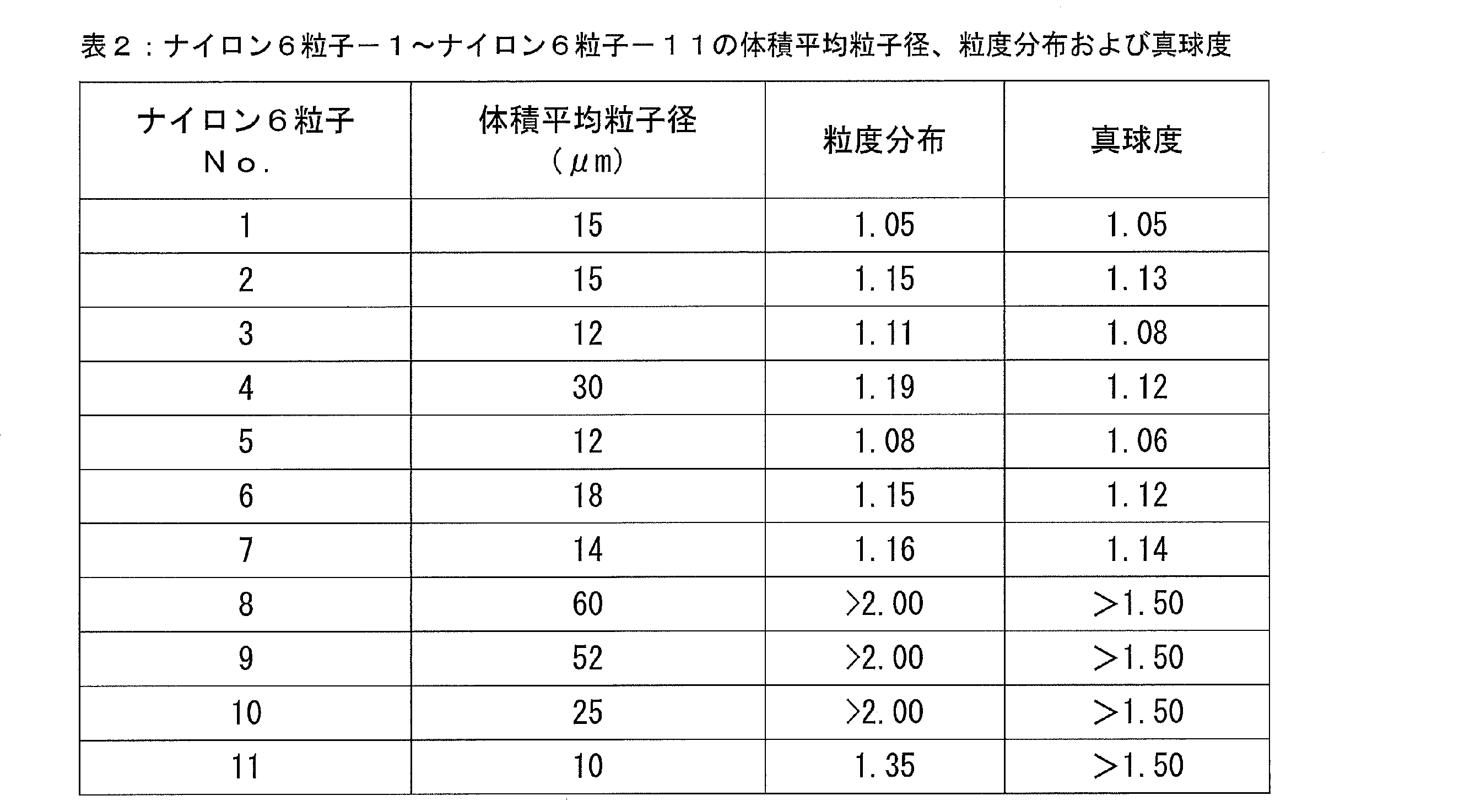
- ERAION 9000 electron beam three-dimensional roughness analyzer
- Table 2 shows the average of the volume average particle size, particle size distribution, and sphericity of nylon 6 particle-1 to nylon 6 particle-11. Further, FIG. 2 shows an SEM image of nylon 6 particle-1, FIG. 3 shows an SEM image of nylon 6 particle-8, and FIG. 4 shows an SEM image of nylon 6 particle-11. 2 and 4 are SEM images taken at a magnification of 5000 times and FIG. 3 at a magnification of 1000 times, respectively.
- nylon 6 solution is cooled and manufactured while maintaining the cooling rate at 5 ° C./min or more and 10 ° C./min or less, so that the particle size distribution is 1.00 or more and 1.20 or less and the sphericity is Nylon 6 particles (nylon particles-1 to nylon particles-7) having a particle size of 1.00 to 1.15 were obtained.
- FIG. 2 which is an SEM image of nylon 6 particle-1, nylon particle-1 to nylon particle-7 are not cracked or partially chipped and have a shape close to a true sphere. It was.
- Nylon 6 Particles-8 produced without using an inorganic salt had a wide particle size distribution, a large sphericity, and an irregular shape as is apparent from the SEM image of FIG.
- Nylon 6 particles-9 produced with a cooling rate of nylon 6 solution higher than 10 ° C./min
- nylon 6 particles-10 produced with a cooling rate of nylon 6 solution less than 1 ° C./min
- Nylon 6 particles-11 produced with a cooling rate higher than 10 ° C./minute in the middle have a wide particle size distribution and a large sphericity, and as is clear from FIG. 4 which is an SEM image, There were many particles that were partially chipped or distorted.
- nylon 6 particles having a narrower particle size distribution and a shape closer to a true sphere can be produced. Moreover, the volume average particle diameter and sphericity of the nylon 6 particles produced can be easily adjusted by the concentration of the inorganic salt.
- Nylon 6 particles produced by the method of the present invention can produce a shaped article with higher accuracy and higher mechanical strength by, for example, a powder bed fusion method. Therefore, it is considered that the present invention contributes to the further spread of the use of nylon 6 particles, in particular, the production of three-dimensional shaped objects from the nylon 6 particles by the powder bed fusion bonding method.
Landscapes
- Chemical & Material Sciences (AREA)
- Engineering & Computer Science (AREA)
- Mechanical Engineering (AREA)
- Health & Medical Sciences (AREA)
- Chemical Kinetics & Catalysis (AREA)
- Medicinal Chemistry (AREA)
- Polymers & Plastics (AREA)
- Organic Chemistry (AREA)
- Manufacturing & Machinery (AREA)
- Materials Engineering (AREA)
- Processes Of Treating Macromolecular Substances (AREA)
- Compositions Of Macromolecular Compounds (AREA)
Abstract
本発明は、得られる粒子の形状を真球に近くし、かつ、粒度分布を狭くすることができる、ナイロン6粒子の製造方法を提供することを目的とする。本発明は、ナイロン6、無機塩および多価アルコールを加熱しながら混合して得られる、上記ナイロン6が前記多価アルコールに溶解した溶液を、冷却する工程を含む、ナイロン6粒子の製造方法に関する。上記冷却する工程において、冷却速度を5℃/分以上10℃/分以下に保持しながら、ナイロン6のガラス転移温度以下の温度まで、上記溶液を冷却する。
Description
本発明は、ナイロン6粒子の製造方法および立体造形物の製造方法に関する。
粒子径が数μmから数十μm程度の、ナイロン6を主成分として含む粒子(以下、単に「ナイロン6粒子」ともいう。)を作製する方法として、ナイロン6を加熱溶解させた溶液を冷却してナイロン6を析出させ、粒子状に凝集させる方法が知られている。この方法によれば、析出したナイロン6は表面張力によって凝集するため、ボールミルなどでナイロン6を物理的に粉砕して上記粒子径を有する粒子を作製する方法よりも、より真球に近い形状を有する粒子を得ることができる。
特許文献1では、ナイロン6、塩化カルシウムおよびエチレングリコールを混合および加熱してナイロン6を溶解させた溶液を冷却すると、より真球に近い形状を有し、かつ、より粒度分布が狭いナイロン6粒子が得られるとされている。特許文献1には、上記溶液を急冷することが好ましいと記載されており、特許文献1の実施例では、ナイロン6を溶液させた溶液を120℃まで放冷した後、溶液の内容物をトレーに移して急冷して、ナイロン6粒子を作製している。
また、特許文献2では、フェノール類にポリアミドを溶解し、さらにポリアミドの非溶媒と水を混合して均一な溶液を形成した後、ポリマーを析出させることで、ポリアミド6などの粒子を作製している。
ナイロン6粒子は、塗料、化粧品基剤、潤滑油や切削油などの添加剤などの幅広い用途を有する。また、ナイロン6粒子は、粉末床溶融結合法による立体造形物の製造用の材料として用いることも可能である。
粉末床溶融結合法とは、立体造形物を製造する方法の一つである。粉末床溶融結合法では、樹脂材料または金属材料を含む粒子を含む粉末材料を平らに敷き詰めて薄膜を形成し、薄膜上の所望の位置にレーザーを照射して、粉末材料に含まれる粒子を選択的に焼結または溶融させて結合させる(以下、焼結または溶融によって粒子が結合することを単に「溶融結合」ともいう。)ことで、立体造形物を厚さ方向に微分割した層(以下、単に「造形物層」ともいう。)のひとつを形成する。こうして形成された層の上に、さらに粉末材料を敷き詰め、レーザーを照射して粉末材料に含まれる粒子を選択的に溶融結合させることで、次の造形物層を形成する。この手順を繰り返して、造形物層を積み上げていくことで、所望の形状の立体造形物が製造される。
特許文献1では、塩化カルシウムの存在下でナイロン6をエチレングリコールに溶解させた後に120℃まで放冷し、その後、溶液の内容物をトレーに移して急冷することで、より真球に近い形状を有し、かつ、より粒子径が均一であるナイロン6粒子が得られるとされている。しかしながら、特許文献1に記載の方法に基づいてナイロン6粒子を作製しても、真球に近い形状の粒子を得ることは難しく、また、粒度分布も十分に狭くすることは難しいのが実情である。特に、特許文献1に記載の方法で得られたナイロン6粒子には、割れたり部分的に欠けたりするものが多く存在することが判明している。
上述した様々な用途において、より真球に近い形状を有し、かつ、粒度分布がより狭いナイロン6粒子が好ましく用いられる。たとえば、粉末床溶融結合法などの立体造形に用いる粒子の形状が真球から大きく外れていたり、粒度分布が広かったりすると、粉末材料を敷き詰めたときに粒子間に隙間などが生じやすい。上記隙間が生じると、立体造形物の造形精度が高まりにくくなり、また、上記隙間に由来する欠損が立体造形物に生じるため、立体造形物の機械的強度も高まりにくくなる。
そのため、より真球に近い形状を有し、かつ、粒度分布が狭いナイロン6粒子を製造できる方法の開発が望まれている。
本発明は、上記課題に鑑みてなされたものであり、得られる粒子の形状を真球に近くし、かつ、粒度分布を狭くすることができる、ナイロン6粒子の製造方法、および、上記製造方法で製造されたナイロン6粒子を用いる立体造形物の製造方法を提供することを、その目的とする。
本発明は、以下のナイロン6粒子の製造方法および立体造形物の製造方法に関する。
[1]ナイロン6、無機塩および多価アルコールを加熱しながら混合して得られる、前記ナイロン6が前記多価アルコールに溶解した溶液を、冷却速度を5℃/分以上10℃/分以下に保持しながらナイロン6のガラス転移温度以下の温度まで冷却する工程を含む、ナイロン6粒子の製造方法。
[2]前記溶液中の前記無機塩の濃度は、前記溶液の全質量に対して0.010質量%以上7.5質量%以下である、[1]に記載の製造方法。
[3]前記溶液中の前記ナイロン6の濃度は、前記溶液の全質量に対して1.0質量%以上30質量%以下である、[1]または[2]に記載の製造方法。
[4]前記多価アルコールの沸点は、ナイロン6の融点より50℃低い温度以上である、[1]~[3]のいずれかに記載の製造方法。
[5]ナイロン6、無機塩および多価アルコールを加熱しながら混合して、前記ナイロン6が前記多価アルコールに溶解した溶液を得る工程をさらに有し、前記加熱後の前記溶液の温度は、上記多価アルコールの沸点よりも低い温度である、[1]~[4]のいずれかに記載の製造方法。
[6]前記冷却によって得られるナイロン6粒子の体積平均粒子径は、12μm以上60μm以下である、[1]~[5]のいずれかに記載の製造方法。
[7]前記冷却によって得られるナイロン6粒子の数平均粒子径に対する体積平均粒子径の比率(体積平均粒子径/数平均粒子径)は、1.00以上1.20以下である、[1]~[6]のいずれかに記載の製造方法。
[8]前記冷却によって得られるナイロン6粒子の長径と短径との比率(長径/短径)の平均は、1.00以上1.15以下である、[1]~[7]のいずれかに記載の製造方法。
[9][1]~[8]のいずれかに記載の製造方法で製造されたナイロン6粒子を含む粉末材料の薄層を形成する工程と、前記形成された薄層にレーザー光を選択的に照射して、前記粉末材料に含まれるナイロン6粒子が焼結または溶融結合してなる造形物層を形成する工程と、前記薄層を形成する工程と、前記造形物層を形成する工程と、をこの順に複数回繰り返し、前記造形物層を積層する工程と、を含む立体造形物の製造方法。
[1]ナイロン6、無機塩および多価アルコールを加熱しながら混合して得られる、前記ナイロン6が前記多価アルコールに溶解した溶液を、冷却速度を5℃/分以上10℃/分以下に保持しながらナイロン6のガラス転移温度以下の温度まで冷却する工程を含む、ナイロン6粒子の製造方法。
[2]前記溶液中の前記無機塩の濃度は、前記溶液の全質量に対して0.010質量%以上7.5質量%以下である、[1]に記載の製造方法。
[3]前記溶液中の前記ナイロン6の濃度は、前記溶液の全質量に対して1.0質量%以上30質量%以下である、[1]または[2]に記載の製造方法。
[4]前記多価アルコールの沸点は、ナイロン6の融点より50℃低い温度以上である、[1]~[3]のいずれかに記載の製造方法。
[5]ナイロン6、無機塩および多価アルコールを加熱しながら混合して、前記ナイロン6が前記多価アルコールに溶解した溶液を得る工程をさらに有し、前記加熱後の前記溶液の温度は、上記多価アルコールの沸点よりも低い温度である、[1]~[4]のいずれかに記載の製造方法。
[6]前記冷却によって得られるナイロン6粒子の体積平均粒子径は、12μm以上60μm以下である、[1]~[5]のいずれかに記載の製造方法。
[7]前記冷却によって得られるナイロン6粒子の数平均粒子径に対する体積平均粒子径の比率(体積平均粒子径/数平均粒子径)は、1.00以上1.20以下である、[1]~[6]のいずれかに記載の製造方法。
[8]前記冷却によって得られるナイロン6粒子の長径と短径との比率(長径/短径)の平均は、1.00以上1.15以下である、[1]~[7]のいずれかに記載の製造方法。
[9][1]~[8]のいずれかに記載の製造方法で製造されたナイロン6粒子を含む粉末材料の薄層を形成する工程と、前記形成された薄層にレーザー光を選択的に照射して、前記粉末材料に含まれるナイロン6粒子が焼結または溶融結合してなる造形物層を形成する工程と、前記薄層を形成する工程と、前記造形物層を形成する工程と、をこの順に複数回繰り返し、前記造形物層を積層する工程と、を含む立体造形物の製造方法。
本発明によれば、得られる粒子の形状を真球に近くし、かつ、粒度分布を狭くすることができる、ナイロン6粒子の製造方法、上記製造方法で製造されたナイロン6粒子を用いる立体造形物の製造方法、および、上記製造方法で製造されたナイロン6粒子を用いて立体造形物を製造できる立体造形装置が提供される。
前述の課題を解決すべく、本発明者らは、ナイロン6を無機塩と共に多価アルコールに加熱溶解させた溶液(以下、単に「ナイロン6溶液」ともいう。)を冷却して、ナイロン6を析出させて粒子状に凝集させる、ナイロン6粒子の製造方法について鋭意検討および実験を行った。その結果、本発明者らは、特許文献1に記載の方法のようにナイロン6溶液を急冷せず、より遅い冷却速度を保持しながら、ナイロン6のガラス転移温度以下の温度までナイロン6溶液を冷却することで、より真球に近い形状を有する粒子が作製され、かつ、得られる粒子の粒度分布がより狭くなることを見出した。
この理由は必ずしも定かではないが、冷却速度を遅くすることで、析出したナイロン6の温度分布がより均一になり、表面張力がより一様に分布するため、析出したナイロン6がより均一に凝集して真球に近い形状になりやすくなるものと考えられる。これに対し、特許文献1のように急冷して粒子を形成させると、析出したナイロン6の温度分布にムラが生じやすく、表面張力の大きさが局所的に異なってしまい、析出したナイロン6が均一に凝集しにくくなるため、得られるナイロン6粒子の粒子径が均一になりにくく、かつ、ナイロン粒子6の形状が球形になりにくくなると考えられる。また、凝集したナイロン6粒子内に上記温度分布が残存すると、ナイロン6粒子内に歪みが生じやすくなり、得られるナイロン6粒子に割れや部分的な欠けが発生しやすくなる結果、微粉が発生して粒度分布を広くしてしまうものと考えられる。
なお、特許文献2においては、フェノール類にポリアミドを溶解し、さらにポリアミドの非溶媒と水を混合して均一な溶液を形成した後、ポリマーを析出させることでポリアミド粒子を得ることが提案されている。しかしながら、この手法で得られるポリアミド粒子は、表面が過度に多孔質になりやすく、また、粒度分布も十分に狭くはならず、粉末床溶融結合法などの立体造形に適する粒子を得ることが難しい。また、フェノール類を溶媒に用いることは安全性の面からも好ましくない。これに対し、上記方法によれば、より安全性が高い多価アルコールを溶媒として用いつつ、ナイロン6粒子の形状をより球形に近くし、かつ、粒度分布もより狭くすることが可能である。
1.ナイロン6粒子の製造方法
上記知見に基づく、本発明の一実施態様は、ナイロン6溶液を、冷却速度を5℃/分以上10℃/分以下に保持しながら冷却する工程を含む、ナイロン6粒子の製造方法に関する。本実施形態は、たとえば、図1のフローチャートに示すように、ナイロン6溶液を調製する工程(工程S101)、ナイロン6溶液を冷却する工程(工程S102)、およびナイロン6粒子を回収する工程(工程S103)を含む。
上記知見に基づく、本発明の一実施態様は、ナイロン6溶液を、冷却速度を5℃/分以上10℃/分以下に保持しながら冷却する工程を含む、ナイロン6粒子の製造方法に関する。本実施形態は、たとえば、図1のフローチャートに示すように、ナイロン6溶液を調製する工程(工程S101)、ナイロン6溶液を冷却する工程(工程S102)、およびナイロン6粒子を回収する工程(工程S103)を含む。
1-1.ナイロン6溶液を調製する工程(工程S101)
上記ナイロン6溶液は、ナイロン6、無機塩および多価アルコールを加熱しながら混合して、調製することができる。なお、ナイロン6が溶解するとは、後述する加熱温度の下限以上に加熱した結果、ナイロン6が目視で確認できない状態になることを意味する。
上記ナイロン6溶液は、ナイロン6、無機塩および多価アルコールを加熱しながら混合して、調製することができる。なお、ナイロン6が溶解するとは、後述する加熱温度の下限以上に加熱した結果、ナイロン6が目視で確認できない状態になることを意味する。
上記多価アルコールは、常温で液体であり、かつ、加熱してナイロン6を十分に溶解できるものであればよい。ナイロン6粒子は、加熱された溶媒中ではナイロン6の融点(225℃)よりも低い温度で溶媒に溶解するため、上記多価アルコールとしては、ナイロン6の融点から50℃低い温度以上の温度に沸点を有するものを用いることが好ましい。このような多価アルコールの例には、エチレングリコール、トリエチレングリコール、プロピレングリコール、ジプロピレングリコール、1,3-ブチレングリコールおよび1,5-ペンタンジオールなどが含まれる。これらのうち、加熱によりナイロン6をより溶解しやすくする観点からは、ナイロン6の融点よりも高い沸点を持つ、ジプロピレングリコールや1,5-ペンタンジオールが好ましい。上記多価アルコールは、1種類でも2種類以上を併用してもよい。2種類の多価アルコールを併用するときは、ナイロン6溶液が含有する最も沸点が低い多価アルコールの沸点がナイロン6の融点よりも高いことが好ましい。
なお、本実施形態の安全性を高める観点からは、上記ナイロン6溶液における芳香族アルコールの濃度は、ナイロン6溶液の全質量に対して10質量%以下であることが好ましく、5質量%以下であることがより好ましく、実質的に含まないことがさらに好ましい。上記芳香族アルコールの例には、クレゾール類およびフェノール類の化合物が含まれる。
上記無機塩は、ナイロン6の溶解を促進する。また、上記無機塩は、冷却時のナイロン6の析出速度を調整して、析出したナイロン6が凝集してなるナイロン6粒子の体積平均粒子径を、所望の範囲に調整することができる。上記無機塩の例には、アルカリ金属及びアルカリ土類金属から選択される少なくとも1種の元素と、塩酸、硫酸、硝酸、酢酸および炭酸等の酸と、の塩が含まれる。好ましくは、上記無機塩には、リチウム、ナトリウム、カリウム及びカルシウムから選択される少なくとも1種と上記酸との塩が含まれ、具体的には、塩化カルシウム、塩化リチウム、臭化リチウム、ヨウ化カリウム、臭化ナトリウム、酢酸ナトリウム、および、臭化カルシウムなどが含まれる。これらのうち、ハンドリング性を良くする観点からは、塩化カルシウムおよび塩化リチウムが好ましい。上記無機塩は、1種類でも2種類以上を併用してもよい。
上記無機塩の濃度は、ナイロン6溶液の全質量に対して、0.010質量%以上7.5質量%以下とすることが好ましい。上記無機塩の濃度が0.010質量%以上であると、上記多価アルコールにナイロン6を十分に溶解させることができる。また、上記無機塩の濃度が0.010質量%以上であると、冷却によりナイロン6がより均一に析出するため、得られるナイロン6粒子の形状が真球に近くなり、かつ、得られるナイロン6粒子の粒度分布が狭くなると考えられる。一方で、上記無機塩の濃度を7.5質量%より高くしても、得られるナイロン6粒子の体積平均粒子径および形状を調整する効果はあまり大きくならない一方、無機塩の濃度が過剰になることにより、得られるナイロン6粒子の性質が変化しやすくなる。なお、無機塩の濃度を上記範囲で変更することで、ナイロン6粒子の体積平均粒子径を所望の範囲に調整することができるため、無機塩の濃度は、得ようとするナイロン6粒子の体積平均粒子径に応じて決定すればよい。このとき、無機塩の濃度を高くするほど得られるナイロン6粒子の体積平均粒子径は小さくなり、得られるナイロン6粒子の形状は真球に近くなる。たとえば、体積平均粒子径が12μm以上60μm以下のナイロン6粒子を得る観点からは、上記無機塩の濃度は、ナイロン6溶液の全質量に対して、0.050質量%以上7.5質量%以下であることが好ましく、1.0質量%以上7.5質量%以下であることがより好ましく、2.0質量%以上7.5質量%以下であることがさらに好ましい。
上記ナイロン6の濃度は、ナイロン6溶液の全質量に対して、1.0質量%以上30質量%以下とすることが好ましい。上記ナイロン6の濃度が1.0質量%以上であると、析出したナイロン6が互いに近接して析出するため、ナイロン6が十分に凝集してナイロン6粒子を形成する。上記ナイロン6の濃度が30質量%以下であると、適度な量のナイロン6が析出して適度に凝集するため、得られるナイロン6粒子の形状が真球に近くなり、かつ、得られる粒子の粒度分布が狭くなると考えられる。たとえば、体積平均粒子径が12μm以上60μm以下のナイロン6粒子を得る観点からは、上記ナイロン6の濃度は、ナイロン6溶液の全質量に対して、1.0質量%以上30質量%以下であることが好ましく、3.0質量%以上20質量%以下であることがより好ましく、5質量%以上20質量%以下であることがさらに好ましく、10質量%以上20質量%以下であることがさらに好ましい。
加熱後のナイロン6溶液の温度(以下、単に「加熱温度」ともいう。)は、ナイロン6が上記多価アルコールに溶解する温度とすればよく、たとえば、170℃以上300℃以下とすることができる。ただし、上記多価アルコールの蒸発によるナイロン6の析出を防ぐため、加熱温度は、上記多価アルコールの沸点よりも低い温度とすることが好ましい。また、加熱温度は、ナイロン6が溶解する限りにおいて、ナイロン6の融点(225℃)よりも低い温度でもよいが、ナイロン6を確実に溶解させる観点からは、ナイロン6の融点以上の温度であることが好ましい。
ナイロン6を均一に溶解させるため、加熱は、混合しながら行うことが好ましい。
なお、本工程は、上記手順によるナイロン6溶液の調製に限定されるものではなく、他の方法でナイロン6溶液を調製してもよいし、すでに調製されたナイロン6溶液を入手して、以下の工程に用いてもよい。
1-2.ナイロン6溶液を冷却する工程(工程S102)
本実施形態において、前記ナイロン6溶液は、冷却速度を5℃/分以上10℃/分以下に保持しながら、ナイロン6のガラス転移温度以下の温度まで冷却される。
本実施形態において、前記ナイロン6溶液は、冷却速度を5℃/分以上10℃/分以下に保持しながら、ナイロン6のガラス転移温度以下の温度まで冷却される。
本実施形態においては、上記冷却速度でナイロン6のガラス転移温度以下の温度まで冷却することで、得られるナイロン6粒子の形状が真球に近くなり、かつ、得られる粒子の粒度分布が狭くなる。これは、冷却中のナイロン6溶液中の熱分布に偏りが生じにくくなり、ナイロン6溶液の全体が均一に冷却されるため、析出したナイロン6の温度分布がより均一になり、表面張力がより一様に分布するためだと考えられる。これに対し、冷却速度が10℃/分より速いと、ナイロン6溶液の温度分布にムラが生じ、析出したナイロン6の表面張力に偏りが生じて、析出したナイロン6がより均一に凝集しにくくなるため、得られるナイロン6粒子の粒子径が均一になりにくく、かつナイロン粒子6の形状が球形になりにくくなると考えられる。また、冷却速度が10℃/分より速いと、凝集したナイロン6粒子内に上記温度分布が残存し、ナイロン6粒子内に歪みが生じやすくなり、得られるナイロン6粒子に割れや部分的な欠けが発生しやすくなると考えられる。冷却速度が5℃/分より遅いと、球形に凝集したナイロン6粒子同士がさらに凝集してしまうおそれがある。
上記冷却速度は、公知の手段で制御することができる。冷却速度をより制御しやすくする観点からは、窒素ガスやアルゴンガスなどの不活性ガスが充填された密閉容器中で上記ナイロン6溶液を冷却することが好ましい。ナイロン6溶液が高温であるとき(たとえば、ナイロン6溶液の温度が100℃以上であるとき)に、室温の環境に静置して放冷することで、冷却速度を上記範囲とすることができる。このとき、冷却速度が5℃/分より遅くなるようであれば、たとえば上記不活性ガスの濃度を高めるなどして、冷却速度を5℃/分以上に制御することができる。ナイロン6溶液が冷却されると(たとえば、ナイロン6溶液の温度が100℃未満になると)、冷却速度がさらに遅くなる可能性があるが、たとえばナイロン6溶液が入っている容器の周囲に水を巡らせるなどの方法で外温を調整して、冷却速度を5℃/分以上に制御することができる。
本工程において、ナイロン6のガラス転移温度(50℃)以下の温度まで上記冷却速度を保持しながら冷却することで、凝集したナイロン6粒子が十分に固化するため、ナイロン6粒子の崩壊や変形などもより生じにくくなると考えられる。ナイロン6粒子をより十分に固化して崩壊や変形しにくくする観点からは、ナイロン6溶液を45℃まで冷却することが好ましく、35℃まで冷却することがより好ましい。また、後の回収工程などをより容易に行う観点からは、ナイロン6溶液を室温まで冷却することが好ましい。
温度低下に伴うナイロン6溶液の粘度上昇により、後の回収工程が困難になったり、ナイロン6が不均一に析出していびつな形に凝集したりすることを抑制する観点から、冷却はナイロン6溶液を混合しながら行うことが好ましい。このときの撹拌速度は、100rpm以上1000rpm以下であることが好ましく、150rpm以上750rpm以下であることがより好ましく、200rpm以上600rpm以下であることがさらに好ましい。なお、ナイロン6溶液の温度が低くなるほど多価アルコールの粘度は高くなるため、ナイロン6溶液を冷却する過程において、撹拌速度を上昇させてもよい。
1-3.ナイロン6粒子を回収する工程(工程S103)
上記室温までの冷却の後に、得られたナイロン6粒子を回収してもよい。ナイロン6粒子の回収は、濾過などの公知の方法で行うことができる。
上記室温までの冷却の後に、得られたナイロン6粒子を回収してもよい。ナイロン6粒子の回収は、濾過などの公知の方法で行うことができる。
1-4.得られるナイロン6粒子
1-4-1.走査型電子顕微鏡(SEM)による画像
図2に、本実施形態において得られるナイロン6粒子を走査型電子顕微鏡(SEM)で撮像して得られる画像を示す。図2は、上記多価アルコールをジプロピレングリコール、上記無機塩を塩化カルシウムとして調製したナイロン6溶液を、冷却速度を5℃/分以上10℃/分以下に保持しながら室温まで冷却して得られたナイロン6粒子のSEM画像である。図2は、上記無機塩の濃度を5.7質量%として製造したナイロン6粒子を、倍率を5000倍にして撮像したSEM画像である。
1-4-1.走査型電子顕微鏡(SEM)による画像
図2に、本実施形態において得られるナイロン6粒子を走査型電子顕微鏡(SEM)で撮像して得られる画像を示す。図2は、上記多価アルコールをジプロピレングリコール、上記無機塩を塩化カルシウムとして調製したナイロン6溶液を、冷却速度を5℃/分以上10℃/分以下に保持しながら室温まで冷却して得られたナイロン6粒子のSEM画像である。図2は、上記無機塩の濃度を5.7質量%として製造したナイロン6粒子を、倍率を5000倍にして撮像したSEM画像である。
図2から明らかなように、本実施形態において得られたナイロン6粒子は、より真球に近い形状を有している。なお、後述する実施例からも明らかなように、本実施形態において得られたナイロン6粒子は、粒度分布もより狭くなる。また、添加する無機塩の濃度が高いほど、得られるナイロン6粒子の体積平均粒子径は小さくなり、より真球に近い形状のナイロン粒子が得られる。
これに対し、図3は、上記多価アルコールをジプロピレングリコールとし、上記無機塩を用いずに調製したナイロン6溶液を、冷却速度を5℃/分以上10℃/分以下に保持しながら室温まで冷却して得られたナイロン6粒子を、倍率を1000倍にして撮像したSEM画像である。また、図4は、特許文献1の実施例1に記載の方法で、120℃まで冷却した後は急冷して作製したナイロン6粒子を、倍率を5000倍にして撮像したSEM画像である。
図3から明らかなように、無機塩を添加せずに作製したナイロン6粒子はいびつな形状をしている。また、図4から明らかなように、途中で冷却速度を速くして作製したナイロン6粒子は、割れたり部分的に欠けたりしているものが多い。このように、無機塩を添加しなかったり、途中で冷却速度を速くしたりしてナイロン6粒子を製造しても、真球に近い形状を有するナイロン6粒子は得られない。
1-4-2.体積平均粒子径、粒度分布および形状
本実施形態において得られるナイロン6粒子の体積平均粒子径は、無機塩の濃度を変更することで、所望の程度に調整できる。体積平均粒子径は、ナイロン6粒子の用途に応じて選択することができるが、たとえば、粉末床溶融結合法による立体造形物の製造用の材料とするときは、上記体積平均粒子径は、12μm以上60μm以下であることが好ましく、15μm以上55μm以下であることが好ましく、15μm以上50μm以下であることがより好ましく、20μm以上50μm以下であることがさらに好ましい。
本実施形態において得られるナイロン6粒子の体積平均粒子径は、無機塩の濃度を変更することで、所望の程度に調整できる。体積平均粒子径は、ナイロン6粒子の用途に応じて選択することができるが、たとえば、粉末床溶融結合法による立体造形物の製造用の材料とするときは、上記体積平均粒子径は、12μm以上60μm以下であることが好ましく、15μm以上55μm以下であることが好ましく、15μm以上50μm以下であることがより好ましく、20μm以上50μm以下であることがさらに好ましい。
また、本実施形態によれば、粒度分布を示す指標である、数平均粒子径に対する体積平均粒子径の比率(体積平均粒子径/数平均粒子径)が、1.00以上1.20となるナイロン6粒子を製造することができる。上記比率は、無機塩の濃度や冷却速度などを変更して、所望の程度に調整できる。たとえば、上記比率は、1.00以上1.18以下であることが好ましく、1.00以上1.15以下であることがより好ましく、1.00以上1.10以下であることがさらに好ましい。
ナイロン6粒子の体積平均粒子径および数平均粒子径は、レーザー回折・散乱式の粒子径分布測定装置(たとえば、マイクロトラック・ベル株式会社製、マイクロトラックMT3000II)によって測定した体積平均粒子径および数平均粒子径とすることができる。
また、本実施形態において得られるナイロン6粒子の形状が真球にどの程度近いかを示す指標である、長径と短径との比率(長径/短径)の平均(以下、単に「真球度」ともいう。)も、無機塩の濃度を変更することで、所望の程度に調整できる。たとえば、上記真球度は、1.00以上1.15以下であることが好ましく、1.00以上1.12以下であることが好ましく、1.00以上1.10以下であることがより好ましく、1.00以上1.05以下であることがさらに好ましい。
1-4-3.用途
本実施形態において得られるナイロン6粒子は、立体造形の材料、塗料、化粧品基剤、潤滑油や切削油などの添加剤などに用いることができる。
本実施形態において得られるナイロン6粒子は、立体造形の材料、塗料、化粧品基剤、潤滑油や切削油などの添加剤などに用いることができる。
たとえば、本実施形態において得られるナイロン6粒子は、粉末床溶融結合法による立体造形の材料として用いると、粒子の取り扱いが特に容易である。また、敷き詰めたときに生じる粒子間の隙間を従来のナイロン6粒子よりも少なくすることができるため、立体造形物の造形精度がより高く、かつ、機械的強度がより高い立体造形物を製造することができる。
2.立体造形物の製造方法
本実施形態は、前記方法で製造したナイロン6粒子を用いた、立体造形物の製造方法に係る。本実施形態に係る方法は、前記方法で製造したナイロン6粒子を含む粉末材料を用いるほかは、通常の粉末床溶融結合法と同様に行い得る。具体的には、本実施形態に係る方法は、(2-1)前記方法で製造したナイロン6粒子を含む粉末材料の薄層を形成する工程と、(2-2)形成された薄層にレーザー光を選択的に照射して、前記粉末材料に含まれるナイロン6粒子が焼結または溶融結合してなる造形物層を形成する工程と、(2-3)工程(2-1)および工程(2-2)をこの順に複数回繰り返し、前記造形物層を積層する工程と、を含む。工程(2-2)により、立体造形物を構成する造形物層のひとつが形成され、さらに工程(2-3)で工程(2-1)および工程(2-2)を繰り返し行うことで、立体造形物の次の層が積層されていき、最終的な立体造形物が製造される。
本実施形態は、前記方法で製造したナイロン6粒子を用いた、立体造形物の製造方法に係る。本実施形態に係る方法は、前記方法で製造したナイロン6粒子を含む粉末材料を用いるほかは、通常の粉末床溶融結合法と同様に行い得る。具体的には、本実施形態に係る方法は、(2-1)前記方法で製造したナイロン6粒子を含む粉末材料の薄層を形成する工程と、(2-2)形成された薄層にレーザー光を選択的に照射して、前記粉末材料に含まれるナイロン6粒子が焼結または溶融結合してなる造形物層を形成する工程と、(2-3)工程(2-1)および工程(2-2)をこの順に複数回繰り返し、前記造形物層を積層する工程と、を含む。工程(2-2)により、立体造形物を構成する造形物層のひとつが形成され、さらに工程(2-3)で工程(2-1)および工程(2-2)を繰り返し行うことで、立体造形物の次の層が積層されていき、最終的な立体造形物が製造される。
2-1.粉末材料からなる薄層を形成する工程(工程(2-1))
本工程では、前記方法で製造したナイロン6粒子を含む粉末材料の薄層を形成する。たとえば、粉末供給部から供給された上記粉末材料を、リコーターによって造形ステージ上に平らに敷き詰める。薄層は、造形ステージ上に直接形成してもよいし、すでに敷き詰められている粉末材料またはすでに形成されている造形物層の上に接するように形成してもよい。
本工程では、前記方法で製造したナイロン6粒子を含む粉末材料の薄層を形成する。たとえば、粉末供給部から供給された上記粉末材料を、リコーターによって造形ステージ上に平らに敷き詰める。薄層は、造形ステージ上に直接形成してもよいし、すでに敷き詰められている粉末材料またはすでに形成されている造形物層の上に接するように形成してもよい。
薄層の厚さは、造形物層の厚さに準じて設定できる。薄層の厚さは、製造しようとする立体造形物の精度に応じて任意に設定することができるが、通常、0.01mm以上0.30mm以下である。薄層の厚さを0.01mm以上とすることで、次の層を形成するためのレーザー照射によって下の層のナイロン6粒子が溶融結合したり、下の層の造形層が再溶融したりすることを防ぐことができる。薄層の厚さを0.30mm以下とすることで、レーザーのエネルギーを薄層の下部まで伝導させて、薄層を構成する粉末材料に含まれるナイロン6粒子を、厚み方向の全体にわたって十分に溶融結合させることができる。前記観点からは、薄層の厚さは0.01mm以上0.10mm以下であることがより好ましい。また、薄層の厚み方向の全体にわたってより十分にナイロン6粒子を溶融結合させ、積層間の割れをより生じにくくする観点からは、薄層の厚さは、後述するレーザーのビームスポット径との差が0.10mm以内になるよう設定することが好ましい。
2-2.ナイロン6粒子が焼結または溶融結合してなる造形物層を形成する工程(工程(2-2))
本工程では、形成された粉末材料からなる薄層のうち、造形物層を形成すべき位置にレーザーを選択的に照射し、照射された位置のナイロン6粒子を焼結または溶融結合させる。焼結または溶融結合したナイロン6粒子は、隣接する粉末と溶融し合って焼結体または溶融体を形成し、造形物層となる。このとき、レーザーのエネルギーを受け取ったナイロン6粒子は、すでに形成された層のナイロン6とも焼結または溶融結合するため、隣り合う層間の接着も生じる。
本工程では、形成された粉末材料からなる薄層のうち、造形物層を形成すべき位置にレーザーを選択的に照射し、照射された位置のナイロン6粒子を焼結または溶融結合させる。焼結または溶融結合したナイロン6粒子は、隣接する粉末と溶融し合って焼結体または溶融体を形成し、造形物層となる。このとき、レーザーのエネルギーを受け取ったナイロン6粒子は、すでに形成された層のナイロン6とも焼結または溶融結合するため、隣り合う層間の接着も生じる。
レーザーの波長は、ナイロン6が吸収する範囲内で設定すればよい。このとき、レーザーの波長と、ナイロン6の吸収率が最も高くなる波長との差が小さくなるようにすることが好ましいが、樹脂は様々な波長域の光を吸収し得るので、CO2レーザー等の波長帯域の広いレーザーを用いることが好ましい。たとえば、レーザーの波長は、0.8μm以上12μm以下であることが好ましい。
レーザーの出力時のパワーは、後述するレーザーの走査速度において、ナイロン6が十分に溶融結合する範囲内で設定すればよく、具体的には、5.0W以上60W以下とすることができる。レーザーのエネルギーを低くして、製造コストを低くし、かつ、製造装置の構成を簡易なものにする観点からは、レーザーの出力時のパワーは30W以下であることが好ましく、20W以下であることがより好ましい。
レーザーの走査速度は、製造コストを高めず、かつ、装置構成を過剰に複雑にしない範囲内で設定すればよい。具体的には、1mm/秒以上100mm/秒以下とすることが好ましく、1mm/秒以上80mm/秒以下とすることがより好ましく、2mm/秒以上80mm/秒以下とすることがさらに好ましく、3mm/秒以上80mm/秒以下とすることがさらに好ましく、3mm/秒以上50mm/秒以下とすることがさらに好ましい。
レーザーのビーム径は、製造しようとする立体造形物の形状などに応じて適宜設定することができる。
2-3.造形物層を積層する工程(工程(3))
本工程では、工程(1)および工程(2)を繰り返して、工程(2)によって形成される造形物層を積層する。造形物層を積層していくことで、所望の立体造形物が製造される。
本工程では、工程(1)および工程(2)を繰り返して、工程(2)によって形成される造形物層を積層する。造形物層を積層していくことで、所望の立体造形物が製造される。
2-4.その他
焼結または溶融結合中にナイロン6が酸化などすることによる、立体造形物の機械的強度の低下を防ぐ観点からは、少なくとも工程(2-2)は減圧下または不活性ガス雰囲気中で行うことが好ましい。減圧するときの圧力は10-2Pa以下であることが好ましく、10-3Pa以下であることがより好ましい。本実施形態で使用することができる不活性ガスの例には、窒素ガスおよび希ガスが含まれる。これらの不活性ガスのうち、入手の容易さの観点からは、窒素(N2)ガス、ヘリウム(He)ガスまたはアルゴン(Ar)ガスが好ましい。製造工程を簡略化する観点からは、工程(2-1)および工程(2-2)の両方を減圧下または不活性ガス雰囲気中で行うことが好ましい。
焼結または溶融結合中にナイロン6が酸化などすることによる、立体造形物の機械的強度の低下を防ぐ観点からは、少なくとも工程(2-2)は減圧下または不活性ガス雰囲気中で行うことが好ましい。減圧するときの圧力は10-2Pa以下であることが好ましく、10-3Pa以下であることがより好ましい。本実施形態で使用することができる不活性ガスの例には、窒素ガスおよび希ガスが含まれる。これらの不活性ガスのうち、入手の容易さの観点からは、窒素(N2)ガス、ヘリウム(He)ガスまたはアルゴン(Ar)ガスが好ましい。製造工程を簡略化する観点からは、工程(2-1)および工程(2-2)の両方を減圧下または不活性ガス雰囲気中で行うことが好ましい。
ナイロン6粒子をより焼結または溶融結合させやすくする観点からは、工程(2-2)の前に粉末材料による薄層を予備加熱してもよい。たとえば、ヒーターなどの温度調整装置により、上記造形物層を形成すべき領域を選択的に加熱したり、装置内の全体を予め加熱したりして、薄層の表面をナイロン6の融点よりも15℃以下、好ましくはナイロン6の融点よりも5℃以下にすることができる。
また、形成された造形物層が再び溶融することによる造形物の寸法精度の低下を抑制する観点からは、温度調整装置により、上記造形物層を形成すべき領域を選択的に冷却したり、装置内の全体を冷却したりしてもよい。
3.立体造形装置
本実施形態は、前記方法で製造したナイロン6粒子を含む粉末材料を用いて、立体造形物を製造する装置に係る。本実施形態に係る装置は、前記粉末材料を用いるほかは、粉末床溶融結合法による立体造形物の製造を行う公知の装置と同様の構成とし得る。具体的には、本実施形態に係る立体造形装置500は、その構成を概略的に示す側面図である図5に記載のように、開口内に位置する造形ステージ510、ナイロン6粒子を含む粉末材料の薄膜を前記造形ステージ上に形成する薄膜形成部520、薄膜にレーザーを照射して、前記ナイロン6粒子が溶融結合してなる造形物層を形成するレーザー照射部530、および鉛直方向の位置を可変に造形ステージ510を支持するステージ支持部540、上記各部を支持するベース545を備える。
本実施形態は、前記方法で製造したナイロン6粒子を含む粉末材料を用いて、立体造形物を製造する装置に係る。本実施形態に係る装置は、前記粉末材料を用いるほかは、粉末床溶融結合法による立体造形物の製造を行う公知の装置と同様の構成とし得る。具体的には、本実施形態に係る立体造形装置500は、その構成を概略的に示す側面図である図5に記載のように、開口内に位置する造形ステージ510、ナイロン6粒子を含む粉末材料の薄膜を前記造形ステージ上に形成する薄膜形成部520、薄膜にレーザーを照射して、前記ナイロン6粒子が溶融結合してなる造形物層を形成するレーザー照射部530、および鉛直方向の位置を可変に造形ステージ510を支持するステージ支持部540、上記各部を支持するベース545を備える。
立体造形装置500は、その制御系の主要部を示す図6に記載のように、薄膜形成部520、レーザー照射部530およびステージ支持部540を制御して、前記造形物層を繰り返し形成させて積層させる制御部550、各種情報を表示するための表示部560、ユーザーからの指示を受け付けるためのポインティングデバイス等を含む操作部570、制御部550の実行する制御プログラムを含む各種の情報を記憶する記憶部580、ならびに外部機器との間で立体造形データ等の各種情報を送受信するためのインターフェース等を含むデータ入力部590を備えてもよい。立体造形装置500には、立体造形用のデータを生成するためのコンピューター装置600が接続されてもよい。
造形ステージ510には、薄膜形成部520による薄層の形成およびレーザー照射部530によるレーザーの照射によって造形材層が形成され、この造形材層が積層されることにより、立体造形物が造形される。
薄膜形成部520は、たとえば、造形ステージ510が昇降する開口の縁部と、水平方向にほぼ同一平面上にその縁部がある開口、開口から鉛直方向下方に延在する粉末材料収納部、および粉末材料収納部の底部に設けられ開口内を昇降する供給ピストンを備える粉末供給部521、ならびに供給された粉末材料を造形ステージ510上に平らに敷き詰めて、粉末材料の薄層を形成するリコーター522aを備えた構成とすることができる。
なお、粉末供給部521は、造形ステージ510に対して鉛直方向上方に設けられた粉末材料収納部、およびノズルを備えて、前記造形ステージと水平方向に同一の平面上に、粉末材料を吐出する構成としてもよい。
レーザー照射部530は、レーザー光源531およびガルバノミラー532aを含む。レーザー照射部530は、レーザーの焦点距離を薄層の表面にあわせるためのレンズ(不図示)を備えていてもよい。 レーザー光源531は、前記波長のレーザーを、前記出力で出射する光源であればよい。レーザー光源531の例には、YAGレーザー光源、ファイバレーザー光源およびCO2レーザー光源が含まれる。ガルバノミラー532aは、レーザー光源531から出射されたレーザーを反射してレーザーをX方向に走査するXミラーおよびY方向に走査するYミラーから構成されてもよい。
ステージ支持部540は、造形ステージ510を、その鉛直方向の位置を可変に支持する。すなわち、造形ステージ510は、ステージ支持部540によって鉛直方向に精密に移動可能に構成されている。ステージ支持部540としては、種々の構成を採用できるが、例えば、造形ステージ510を保持する保持部材と、この保持部材を鉛直方向に案内するガイド部材と、ガイド部材に設けられたねじ孔に係合するボールねじ等で構成することができる。
制御部550は、立体造形物の造形動作中、立体造形装置500全体の動作を制御する。
また、制御部550は、中央処理装置等のハードウェアプロセッサを含んでおり、たとえばデータ入力部590がコンピューター装置600から取得した立体造形データを、造形材層の積層方向について薄く切った複数のスライスデータに変換するよう構成されてもよい。スライスデータは、立体造形物を造形するための各造形材層の造形データである。スライスデータの厚み、すなわち造形材層の厚みは、造形材層の一層分の厚さに応じた距離(積層ピッチ)と一致する。
表示部560は、たとえば液晶ディスプレイ、モニタとすることができる。
操作部570は、たとえばキーボードやマウスなどのポインティングデバイスを含むものとすることができ、テンキー、実行キー、スタートキー等の各種操作キーを備えてもよい。
記憶部580は、たとえばROM、RAM、磁気ディスク、HDD、SSD等の各種の記憶媒体を含むものとすることができる。
立体造形装置500は、制御部550の制御を受けて、装置内を減圧する、減圧ポンプなどの減圧部(不図示)、または、制御部550の制御を受けて、不活性ガスを装置内に供給する、不活性ガス供給部(不図示)を備えていてもよい。また、立体造形装置500は、制御部550の制御を受けて、装置内、特には粉末材料による薄層の上面を加熱するヒータ(不図示)を備えていてもよい。
3-1.立体造形装置500を用いた立体造形の例
制御部550は、データ入力部590がコンピューター装置600から取得した立体造形データを、造形材層の積層方向について薄く切った複数のスライスデータに変換する。その後、制御部550は、立体造形装置500における以下の動作の制御を行う。
制御部550は、データ入力部590がコンピューター装置600から取得した立体造形データを、造形材層の積層方向について薄く切った複数のスライスデータに変換する。その後、制御部550は、立体造形装置500における以下の動作の制御を行う。
粉末供給部521は、制御部550から出力された供給情報に従って、モーターおよび駆動機構(いずれも不図示)を駆動し、供給ピストンを鉛直方向上方(図中矢印方向)に移動させ、前記造形ステージと水平方向同一平面上に、粉末材料を押し出す。
その後、リコーター駆動部522は、制御部550から出力された薄膜形成情報に従って水平方向(図中矢印方向)にリコーター522aを移動して、粉末材料を造形ステージ510に運搬し、かつ、薄層の厚さが造形物層の1層分の厚さとなるように粉末材料を押圧する。
その後、レーザー照射部530は、制御部550から出力されたレーザー照射情報に従って、薄膜上の、各スライスデータにおける立体造形物を構成する領域に適合して、レーザー光源531からレーザーを出射し、ガルバノミラー駆動部532によりガルバノミラー532aを駆動してレーザーを走査する。レーザーの照射によって粉末材料に含まれるナイロン6粒子が溶融結合し、造形物層が形成される。
その後、ステージ支持部540は、制御部550から出力された位置制御情報に従って、モーターおよび駆動機構(いずれも不図示)を駆動し、造形ステージ510を、積層ピッチだけ鉛直方向下方(図中矢印方向)に移動する。
表示部560は、必要に応じて、制御部550の制御を受けて、ユーザーに認識させるべき各種の情報やメッセージを表示する。操作部570は、ユーザーによる各種入力操作を受け付けて、その入力操作に応じた操作信号を制御部550に出力する。たとえば、形成される仮想の立体造形物を表示部560に表示して所望の形状が形成されるか否かを確認し、所望の形状が形成されない場合は、操作部570から修正を加えてもよい。
制御部550は、必要に応じて、記憶部580へのデータの格納または記憶部580からのデータの引き出しを行う。
これらの動作を繰り返すことで、造形物層が積層され、立体造形物が製造される。
以下において、本発明の具体的な実施例を説明する。なお、これらの実施例によって、本発明の範囲は限定して解釈されない。
1.ナイロン6粒子の製造
1-1.ナイロン6粒子-1の製造
25gのナイロン6(東レ株式会社製、アミランCM1001(「アミラン」は同社の登録商標))、15gの塩化カルシウム(和光純薬工業株式会社製、試薬特級)、および225gのジプロピレングリコール(東京化成工業株式会社製、沸点230.5℃)を500mL容量のジャケット式フラスコ(東京理化器械株式会社製、BD-5N)に投入して、窒素ガス雰囲気下で撹拌しながら、マントルヒーター(株式会社東京技術研究所製、FN-300W)を用いて225℃まで昇温させた。なお、加熱中および後の冷却中のジプロピレングリコールの温度は、熱電対によって測定した。ジプロピレングリコールの温度が225℃になった後、200rpmで1時間撹拌し、その後、マントルヒーターのジャケットを外して、500rpmで撹拌しながら室温で放冷した。冷却時の温度変化が7℃/分以下になったときは、窒素ガス量を調整して、温度変化が5℃/分を下回らないようにした。冷却時の温度変化が10℃/分より大きくなることはなかった。温度が100℃を下回ったら、温水で冷却して、冷却速度5℃/分以上を保つように室温まで冷却した。その後、フラスコの内容物をフィルターろ過によって回収し、過剰量の純水で洗浄した後、乾燥させてナイロン6粒子-1を得た。
1-1.ナイロン6粒子-1の製造
25gのナイロン6(東レ株式会社製、アミランCM1001(「アミラン」は同社の登録商標))、15gの塩化カルシウム(和光純薬工業株式会社製、試薬特級)、および225gのジプロピレングリコール(東京化成工業株式会社製、沸点230.5℃)を500mL容量のジャケット式フラスコ(東京理化器械株式会社製、BD-5N)に投入して、窒素ガス雰囲気下で撹拌しながら、マントルヒーター(株式会社東京技術研究所製、FN-300W)を用いて225℃まで昇温させた。なお、加熱中および後の冷却中のジプロピレングリコールの温度は、熱電対によって測定した。ジプロピレングリコールの温度が225℃になった後、200rpmで1時間撹拌し、その後、マントルヒーターのジャケットを外して、500rpmで撹拌しながら室温で放冷した。冷却時の温度変化が7℃/分以下になったときは、窒素ガス量を調整して、温度変化が5℃/分を下回らないようにした。冷却時の温度変化が10℃/分より大きくなることはなかった。温度が100℃を下回ったら、温水で冷却して、冷却速度5℃/分以上を保つように室温まで冷却した。その後、フラスコの内容物をフィルターろ過によって回収し、過剰量の純水で洗浄した後、乾燥させてナイロン6粒子-1を得た。
1-2.ナイロン6粒子-2の製造
上記塩化カルシウムを、15gの塩化リチウム(和光純薬工業株式会社製、和光特級)に変更した以外はナイロン6粒子-1の製造と同様にして、ナイロン6粒子-2を得た。
上記塩化カルシウムを、15gの塩化リチウム(和光純薬工業株式会社製、和光特級)に変更した以外はナイロン6粒子-1の製造と同様にして、ナイロン6粒子-2を得た。
1-3.ナイロン6粒子-3の製造
上記ジプロピレングリコールを、225gのエチレングリコール(東京化成工業株式会社製、沸点197℃)に変更した以外はナイロン6粒子-1の製造と同様にして、ナイロン6粒子-3を得た。
上記ジプロピレングリコールを、225gのエチレングリコール(東京化成工業株式会社製、沸点197℃)に変更した以外はナイロン6粒子-1の製造と同様にして、ナイロン6粒子-3を得た。
1-4.ナイロン6粒子-4の製造
上記塩化カルシウムの量を、5gに変更した以外はナイロン6粒子-1の製造と同様にして、ナイロン6粒子-4を得た。
上記塩化カルシウムの量を、5gに変更した以外はナイロン6粒子-1の製造と同様にして、ナイロン6粒子-4を得た。
1-5.ナイロン6粒子-5の製造
上記塩化カルシウムの量を、20gに変更した以外はナイロン6粒子-1の製造と同様にして、ナイロン6粒子-5を得た。
上記塩化カルシウムの量を、20gに変更した以外はナイロン6粒子-1の製造と同様にして、ナイロン6粒子-5を得た。
1-6.ナイロン6粒子-6の製造
上記ナイロン6の量を50gに変更し、上記ジプロピレングリコールを225gのエチレングリコール(東京化成工業株式会社製)に変更した以外はナイロン6粒子-1の製造と同様にして、ナイロン6粒子-6を得た。
上記ナイロン6の量を50gに変更し、上記ジプロピレングリコールを225gのエチレングリコール(東京化成工業株式会社製)に変更した以外はナイロン6粒子-1の製造と同様にして、ナイロン6粒子-6を得た。
1-7.ナイロン6粒子-7の製造
上記ナイロン6の量を10gに変更した以外はナイロン6粒子-1の製造と同様にして、ナイロン6粒子-7を得た。
上記ナイロン6の量を10gに変更した以外はナイロン6粒子-1の製造と同様にして、ナイロン6粒子-7を得た。
1-8.ナイロン6粒子-8の製造
上記無機塩を投入しなかった以外はナイロン6粒子-1の製造と同様にして、ナイロン6粒子-8を得た。
上記無機塩を投入しなかった以外はナイロン6粒子-1の製造と同様にして、ナイロン6粒子-8を得た。
1-9.ナイロン6粒子-9の製造
25gのナイロン6(東レ株式会社製、アミランCM1001(「アミラン」は同社の登録商標))、15gの塩化カルシウム(和光純薬工業株式会社製、試薬特級)、および225gのジプロピレングリコール(東京化成工業株式会社製)を500mL容量のステンレス反応器(加藤ステンレス科学株式会社製、RK80-05)に投入して、窒素ガス雰囲気下で撹拌しながら、マントルヒーター(株式会社東京技術研究所製、FN-300W)を用いて225℃まで昇温させた。なお、加熱中および後の冷却中のジプロピレングリコールの温度は、熱電対によって測定した。ジプロピレングリコールの温度が225℃になった後、200rpmで1時間撹拌し、その後、反応器を過剰量の氷浴につけて、500rpmで撹拌しながら室温まで冷却した。このとき、冷却時の温度変化は、常に10℃/分より大きかった。その後、フラスコの内容物をフィルターろ過によって回収し、過剰量の純水で洗浄した後、乾燥させてナイロン6粒子-9を得た。
25gのナイロン6(東レ株式会社製、アミランCM1001(「アミラン」は同社の登録商標))、15gの塩化カルシウム(和光純薬工業株式会社製、試薬特級)、および225gのジプロピレングリコール(東京化成工業株式会社製)を500mL容量のステンレス反応器(加藤ステンレス科学株式会社製、RK80-05)に投入して、窒素ガス雰囲気下で撹拌しながら、マントルヒーター(株式会社東京技術研究所製、FN-300W)を用いて225℃まで昇温させた。なお、加熱中および後の冷却中のジプロピレングリコールの温度は、熱電対によって測定した。ジプロピレングリコールの温度が225℃になった後、200rpmで1時間撹拌し、その後、反応器を過剰量の氷浴につけて、500rpmで撹拌しながら室温まで冷却した。このとき、冷却時の温度変化は、常に10℃/分より大きかった。その後、フラスコの内容物をフィルターろ過によって回収し、過剰量の純水で洗浄した後、乾燥させてナイロン6粒子-9を得た。
1-10.ナイロン6粒子-10の製造
上記冷却を、マントルヒーターのジャケットをかぶせたままの放冷とした以外は、ナイロン6粒子-9の製造と同様にして、ナイロン6粒子-10を得た。なお、このとき、冷却時の温度変化は、常に1℃/分未満だった。
上記冷却を、マントルヒーターのジャケットをかぶせたままの放冷とした以外は、ナイロン6粒子-9の製造と同様にして、ナイロン6粒子-10を得た。なお、このとき、冷却時の温度変化は、常に1℃/分未満だった。
1-11.ナイロン6粒子-11の製造
17gのナイロン6(東レ株式会社製、アミランCM1001(「アミラン」は同社の登録商標))、23gの塩化カルシウム2水和物(塩化カルシウム:17.3g、水:5.7g、和光純薬工業株式会社製、試薬特級)、および150gのエチレングリコール(東京化成工業株式会社製)を500mL容量のビーカーに投入して、窒素ガス雰囲気下で撹拌しながら、マントルヒーター(株式会社東京技術研究所製、FN-300W)を用いて190℃まで昇温させた。なお、加熱中および後の冷却中のエチレングリコールの温度は、熱電対によって測定した。エチレングリコールの温度が190℃になった後、200rpmで1時間撹拌し、その後、マントルヒーターのジャケットを外して、エチレングリコールの温度が120℃になるまで、500rpmで撹拌しながら室温で放冷した。このとき、冷却時の温度変化は5℃/分以上10℃/分以下だった。温度が120℃を下回った後、析出した粒子をトレーに移して室温まで急冷し、その後乾燥させて、ナイロン6粒子-11を得た。
17gのナイロン6(東レ株式会社製、アミランCM1001(「アミラン」は同社の登録商標))、23gの塩化カルシウム2水和物(塩化カルシウム:17.3g、水:5.7g、和光純薬工業株式会社製、試薬特級)、および150gのエチレングリコール(東京化成工業株式会社製)を500mL容量のビーカーに投入して、窒素ガス雰囲気下で撹拌しながら、マントルヒーター(株式会社東京技術研究所製、FN-300W)を用いて190℃まで昇温させた。なお、加熱中および後の冷却中のエチレングリコールの温度は、熱電対によって測定した。エチレングリコールの温度が190℃になった後、200rpmで1時間撹拌し、その後、マントルヒーターのジャケットを外して、エチレングリコールの温度が120℃になるまで、500rpmで撹拌しながら室温で放冷した。このとき、冷却時の温度変化は5℃/分以上10℃/分以下だった。温度が120℃を下回った後、析出した粒子をトレーに移して室温まで急冷し、その後乾燥させて、ナイロン6粒子-11を得た。
ナイロン6粒子-1~ナイロン6粒子-11の製造に用いたナイロン6の濃度(ナイロン6溶液の全質量に対するナイロン6の質量)、多価アルコールの種類、無機塩の種類および無機塩の量(ナイロン6溶液の全質量に対する無機塩の質量)、ならびに製造時の加熱温度および冷却速度を、表1に示す。

2.ナイロン6粒子の評価
ナイロン6粒子-1~ナイロン6粒子-11の体積平均粒子径および真球度を、下記の方法で測定した。
ナイロン6粒子-1~ナイロン6粒子-11の体積平均粒子径および真球度を、下記の方法で測定した。
2-1.体積平均粒子径
ナイロン6粒子-1~ナイロン6粒子-11をレーザー回折・散乱式の粒子径分布測定装置(マイクロトラック・ベル株式会社製、マイクロトラックMT3000II)に投入して、それぞれのナイロン6粒子の体積平均粒子径を測定した。
ナイロン6粒子-1~ナイロン6粒子-11をレーザー回折・散乱式の粒子径分布測定装置(マイクロトラック・ベル株式会社製、マイクロトラックMT3000II)に投入して、それぞれのナイロン6粒子の体積平均粒子径を測定した。
2-2.粒度分布
ナイロン6粒子-1~ナイロン6粒子-11をレーザー回折・散乱式の粒子径分布測定装置(マイクロトラック・ベル株式会社製、マイクロトラックMT3000II)に投入して、数平均粒子径を測定した。得られた数平均粒子径の値を上記測定した体積平均粒子径の値で除算して、それぞれのナイロン6粒子の粒度分布とした。
ナイロン6粒子-1~ナイロン6粒子-11をレーザー回折・散乱式の粒子径分布測定装置(マイクロトラック・ベル株式会社製、マイクロトラックMT3000II)に投入して、数平均粒子径を測定した。得られた数平均粒子径の値を上記測定した体積平均粒子径の値で除算して、それぞれのナイロン6粒子の粒度分布とした。
2-3.真球度
ナイロン6粒子-1~ナイロン6粒子-11を電子線三次元粗さ解析装置(株式会社エリオニクス製、ERA-9000)で観察し、任意に選択した100個の粒子の長辺と短片の比率を求め、それらの加算平均を算出して、それぞれのナイロン6粒子の真球度とした。
ナイロン6粒子-1~ナイロン6粒子-11を電子線三次元粗さ解析装置(株式会社エリオニクス製、ERA-9000)で観察し、任意に選択した100個の粒子の長辺と短片の比率を求め、それらの加算平均を算出して、それぞれのナイロン6粒子の真球度とした。
2-4.SEMによる撮像
ナイロン6粒子-1~ナイロン6粒子-11を、倍率を500倍、1000倍、および5000倍としてSEMで撮像して、得られた画像中の粒子の形状を観察した。
ナイロン6粒子-1~ナイロン6粒子-11を、倍率を500倍、1000倍、および5000倍としてSEMで撮像して、得られた画像中の粒子の形状を観察した。
ナイロン6粒子-1~ナイロン6粒子-11の体積平均粒子径、粒度分布および真球度の平均を、表2に示す。また、ナイロン6粒子-1のSEM画像を図2に、ナイロン6粒子-8のSEM画像を図3に、ナイロン6粒子-11のSEM画像を図4に、それぞれ示す。なお、図2、図4は、倍率を5000倍に、図3は倍率を1000倍にして、それぞれ撮像したSEM画像である。
ナイロン6溶液を、冷却速度を5℃/分以上10℃/分以下に保持しながら冷却して製造することで、粒度分布が1.00以上1.20以下であり、かつ、真球度が1.00以上1.15以下であるナイロン6粒子(ナイロン粒子-1~ナイロン粒子-7)が得られた。ナイロン6粒子-1のSEM画像である図2に示すように、ナイロン粒子-1~ナイロン粒子-7には割れや部分的な欠けが発生しておらず、真球に近い形状を有していた。
また、無機塩の濃度を、ナイロン6溶液の全質量に対して0.010質量%以上7.5質量%以下の範囲で調整することで、得られるナイロン6粒子の体積平均粒子径を調整することができた。このとき、無機塩の量が多いほど、得られるナイロン6粒子の体積平均粒子径が小さくなり、真球度も小さくなる傾向が見られた(表2のナイロン6粒子1、4および5の比較による。)。
一方で、無機塩を用いずに製造したナイロン6粒子-8は、粒度分布が広く、真球度が大きく、SEM画像である図3からも明らかなように、いびつな形状となっていた。
また、ナイロン6溶液の冷却速度を10℃/分より速くして製造したナイロン6粒子―9も、ナイロン6溶液の冷却速度を1℃/分未満にして製造したナイロン6粒子-10も、粒度分布が広く、真球度が大きくなっており、いびつか形状となっていた。
また、途中で冷却速度を10℃/分より速くして製造したナイロン6粒子-11は、粒度分布が広く、真球度が大きく、SEM画像である図4からも明らかなように、割れたり部分的に欠けたりしていびつな形状となっている粒子が多かった。
本出願は、2016年5月6日出願の日本国出願番号2016-093201号に基づく優先権を主張する出願であり、当該出願の特許請求の範囲、明細書および図面に記載された内容は本出願に援用される。
本発明によれば、より粒度分布が狭く、より真球に近い形状を有するナイロン6粒子を製造することができる。また、製造されるナイロン6粒子の体積平均粒子径および真球度は、無機塩の濃度によって容易に調整することができる。本発明の方法によって製造されるナイロン6粒子は、たとえば粉末床溶融結合法によって、より精度が高く、かつ、より機械的強度がより高い造形物を製造することができる。そのため、本発明は、ナイロン6粒子の使用、特にはナイロン6粒子からの粉末床溶融結合法による立体造形物の製造のさらなる普及に寄与するものと思われる。
500 立体造形装置
510 造形ステージ
520 薄膜形成部
521 粉末供給部
522 リコーター駆動部
522a リコーター
530 レーザー照射部
531 レーザー光源
532 ガルバノミラー駆動部
532a ガルバノミラー
540 ステージ支持部
545 ベース
550 制御部
560 表示部
570 操作部
580 記憶部
590 データ入力部
600 コンピューター装置
510 造形ステージ
520 薄膜形成部
521 粉末供給部
522 リコーター駆動部
522a リコーター
530 レーザー照射部
531 レーザー光源
532 ガルバノミラー駆動部
532a ガルバノミラー
540 ステージ支持部
545 ベース
550 制御部
560 表示部
570 操作部
580 記憶部
590 データ入力部
600 コンピューター装置
Claims (9)
- ナイロン6、無機塩および多価アルコールを加熱しながら混合して得られる、前記ナイロン6が前記多価アルコールに溶解した溶液を、冷却速度を5℃/分以上10℃/分以下に保持しながらナイロン6のガラス転移温度以下の温度まで冷却する工程を含む、ナイロン6粒子の製造方法。
- 前記溶液中の前記無機塩の濃度は、前記溶液の全質量に対して0.010質量%以上7.5質量%以下である、請求項1に記載の製造方法。
- 前記溶液中の前記ナイロン6の濃度は、前記溶液の全質量に対して1.0質量%以上30質量%以下である、請求項1または2に記載の製造方法。
- 前記多価アルコールは、ナイロン6の融点より50℃低い温度以上の温度に沸点を有する、請求項1~3のいずれか1項に記載の製造方法。
- ナイロン6、無機塩および多価アルコールを加熱しながら混合して、前記ナイロン6が前記多価アルコールに溶解した溶液を得る工程をさらに有し、前記加熱後の前記溶液の温度は、上記多価アルコールの沸点よりも低い温度である、請求項1~4のいずれか1項に記載の製造方法。
- 前記冷却によって得られるナイロン6粒子の体積平均粒子径は、12μm以上60μm以下である、請求項1~5のいずれか1項に記載の製造方法。
- 前記冷却によって得られるナイロン6粒子の数平均粒子径に対する体積平均粒子径の比率(体積平均粒子径/数平均粒子径)は、1.00以上1.20以下である、請求項1~6のいずれか1項に記載の製造方法。
- 前記冷却によって得られるナイロン6粒子の長径と短径との比率(長径/短径)の平均は、1.00以上1.15以下である、請求項1~7のいずれか1項に記載の製造方法。
- 請求項1~8のいずれか1項に記載の製造方法で製造されたナイロン6粒子を含む粉末材料の薄層を形成する工程と、
前記形成された薄層にレーザー光を選択的に照射して、前記粉末材料に含まれるナイロン6粒子が焼結または溶融結合してなる造形物層を形成する工程と、
前記薄層を形成する工程と、前記造形物層を形成する工程と、をこの順に複数回繰り返し、前記造形物層を積層する工程と、
を含む立体造形物の製造方法。
Priority Applications (1)
| Application Number | Priority Date | Filing Date | Title |
|---|---|---|---|
| JP2018515422A JP6881439B2 (ja) | 2016-05-06 | 2017-04-20 | ナイロン6粒子の製造方法および立体造形物の製造方法 |
Applications Claiming Priority (2)
| Application Number | Priority Date | Filing Date | Title |
|---|---|---|---|
| JP2016-093201 | 2016-05-06 | ||
| JP2016093201 | 2016-05-06 |
Publications (1)
| Publication Number | Publication Date |
|---|---|
| WO2017191760A1 true WO2017191760A1 (ja) | 2017-11-09 |
Family
ID=60203008
Family Applications (1)
| Application Number | Title | Priority Date | Filing Date |
|---|---|---|---|
| PCT/JP2017/015833 Ceased WO2017191760A1 (ja) | 2016-05-06 | 2017-04-20 | ナイロン6粒子の製造方法および立体造形物の製造方法 |
Country Status (2)
| Country | Link |
|---|---|
| JP (1) | JP6881439B2 (ja) |
| WO (1) | WO2017191760A1 (ja) |
Cited By (3)
| Publication number | Priority date | Publication date | Assignee | Title |
|---|---|---|---|---|
| JP2019084815A (ja) * | 2017-11-09 | 2019-06-06 | 株式会社リコー | 立体造形用粉末、樹脂粉末、及び立体造形物の製造方法 |
| WO2021090768A1 (ja) * | 2019-11-05 | 2021-05-14 | 東レ株式会社 | 3次元造形物を製造するためのポリマー粉末、ポリマー粉末を用いて粉末床溶融結合方式によって3次元造形物を製造する方法、および3次元造形物 |
| CN115214045A (zh) * | 2022-06-24 | 2022-10-21 | 滁州燕荣塑料科技有限公司 | 一种增强尼龙用制粒成型装置及其成型方法 |
Citations (7)
| Publication number | Priority date | Publication date | Assignee | Title |
|---|---|---|---|---|
| JPS5933329A (ja) * | 1982-08-17 | 1984-02-23 | Mochizuki Isao | 微粉末ナイロン6の製造方法 |
| JPS62235333A (ja) * | 1986-04-03 | 1987-10-15 | Sekisui Plastics Co Ltd | ナイロン粉末の製造方法 |
| JPS62240325A (ja) * | 1986-04-11 | 1987-10-21 | Sekisui Plastics Co Ltd | ナイロン粉末の製造方法 |
| JPH0812765A (ja) * | 1994-06-28 | 1996-01-16 | Korea Advanced Inst Of Sci Technol | 結晶性ポリアミド球状粒子粉末の製造方法 |
| JP2002080629A (ja) * | 2000-06-14 | 2002-03-19 | Ube Ind Ltd | ポリアミド多孔質球状粒子およびその製造方法 |
| JP2008150594A (ja) * | 2006-11-21 | 2008-07-03 | Toray Ind Inc | ポリカプロアミド樹脂複合微粒子 |
| JP2013177532A (ja) * | 2012-02-29 | 2013-09-09 | Toray Ind Inc | ポリマー微粒子の製造方法 |
-
2017
- 2017-04-20 JP JP2018515422A patent/JP6881439B2/ja not_active Expired - Fee Related
- 2017-04-20 WO PCT/JP2017/015833 patent/WO2017191760A1/ja not_active Ceased
Patent Citations (7)
| Publication number | Priority date | Publication date | Assignee | Title |
|---|---|---|---|---|
| JPS5933329A (ja) * | 1982-08-17 | 1984-02-23 | Mochizuki Isao | 微粉末ナイロン6の製造方法 |
| JPS62235333A (ja) * | 1986-04-03 | 1987-10-15 | Sekisui Plastics Co Ltd | ナイロン粉末の製造方法 |
| JPS62240325A (ja) * | 1986-04-11 | 1987-10-21 | Sekisui Plastics Co Ltd | ナイロン粉末の製造方法 |
| JPH0812765A (ja) * | 1994-06-28 | 1996-01-16 | Korea Advanced Inst Of Sci Technol | 結晶性ポリアミド球状粒子粉末の製造方法 |
| JP2002080629A (ja) * | 2000-06-14 | 2002-03-19 | Ube Ind Ltd | ポリアミド多孔質球状粒子およびその製造方法 |
| JP2008150594A (ja) * | 2006-11-21 | 2008-07-03 | Toray Ind Inc | ポリカプロアミド樹脂複合微粒子 |
| JP2013177532A (ja) * | 2012-02-29 | 2013-09-09 | Toray Ind Inc | ポリマー微粒子の製造方法 |
Cited By (4)
| Publication number | Priority date | Publication date | Assignee | Title |
|---|---|---|---|---|
| JP2019084815A (ja) * | 2017-11-09 | 2019-06-06 | 株式会社リコー | 立体造形用粉末、樹脂粉末、及び立体造形物の製造方法 |
| WO2021090768A1 (ja) * | 2019-11-05 | 2021-05-14 | 東レ株式会社 | 3次元造形物を製造するためのポリマー粉末、ポリマー粉末を用いて粉末床溶融結合方式によって3次元造形物を製造する方法、および3次元造形物 |
| CN115214045A (zh) * | 2022-06-24 | 2022-10-21 | 滁州燕荣塑料科技有限公司 | 一种增强尼龙用制粒成型装置及其成型方法 |
| CN115214045B (zh) * | 2022-06-24 | 2023-10-20 | 滁州燕荣塑料科技有限公司 | 一种增强尼龙用制粒成型装置及其成型方法 |
Also Published As
| Publication number | Publication date |
|---|---|
| JP6881439B2 (ja) | 2021-06-02 |
| JPWO2017191760A1 (ja) | 2019-03-07 |
Similar Documents
| Publication | Publication Date | Title |
|---|---|---|
| JP7383738B2 (ja) | セラミックス造形用粉体、セラミックス造形物、およびその製造方法 | |
| JP5172941B2 (ja) | 層状に三次元物体を製造する方法で使用するpaek粉末の製造方法、及び三次元物体を層状に製造する方法 | |
| JP6791165B2 (ja) | 粉末材料、立体造形物の製造方法および立体造形装置 | |
| JP6881439B2 (ja) | ナイロン6粒子の製造方法および立体造形物の製造方法 | |
| JP6532497B2 (ja) | 銅粉末及びその製造方法並びに立体造形物の製造方法 | |
| JP7377324B2 (ja) | 銅粉、それを用いた光造形物の製造方法、および銅による光造形物 | |
| WO2016185966A1 (ja) | 粉末材料、立体造形物の製造方法および立体造形装置 | |
| CN111278618B (zh) | 陶瓷造型物的制造方法 | |
| WO2017217302A1 (ja) | 粉末材料、粉末材料の製造方法、立体造形物の製造方法および立体造形装置 | |
| JPWO2018084056A1 (ja) | 金属粉末、粉末焼結積層造形物及びその製造方法 | |
| US20210023778A1 (en) | Resin powder for solid freeform fabrication, device for fabricating solid freeform fabrication object, and method of fabricating solid freeform fabrication object | |
| WO2017163834A1 (ja) | 粉末材料、および立体造形物の製造方法 | |
| Seyfarth et al. | Laser powder bed fusion of glass: A comparative study between CO2 lasers and ultrashort laser pulses | |
| Wang et al. | Porosity, texture, and mechanical properties of pure copper fabricated by fine green laser powder bed fusion | |
| CN106626379B (zh) | 激光制造聚酰胺三维物体的方法和装置 | |
| JP2020190008A (ja) | 有機被覆銅系粉末、有機被覆銅系粉末を用いて形成された銅系材料からなる積層造形物および積層造形物の製造方法ならびに各種金属部品 | |
| WO2020138188A1 (ja) | 粉末積層造形法用粉末およびその製造方法 | |
| JP2015189085A (ja) | 積層造形方法、及び積層造形装置 | |
| JP6806088B2 (ja) | 粉末材料、立体造形物の製造方法および立体造形装置 | |
| TWI742195B (zh) | 熔融玻璃之製造方法及玻璃物品之製造方法 | |
| US20180311735A1 (en) | Manufacturing method and manufacturing apparatus for additively shaped article | |
| JP6179309B2 (ja) | ガラス材の製造方法 | |
| WO2019013069A1 (ja) | 粉末材料、および立体造形物の製造方法 | |
| JP2021004395A (ja) | 積層造形装置 | |
| JPWO2017110799A1 (ja) | 微小な気泡を含有するガラス及びその製造方法 |
Legal Events
| Date | Code | Title | Description |
|---|---|---|---|
| ENP | Entry into the national phase |
Ref document number: 2018515422 Country of ref document: JP Kind code of ref document: A |
|
| NENP | Non-entry into the national phase |
Ref country code: DE |
|
| 121 | Ep: the epo has been informed by wipo that ep was designated in this application |
Ref document number: 17792693 Country of ref document: EP Kind code of ref document: A1 |
|
| 122 | Ep: pct application non-entry in european phase |
Ref document number: 17792693 Country of ref document: EP Kind code of ref document: A1 |