WO2017187954A1 - 導電部材 - Google Patents
導電部材 Download PDFInfo
- Publication number
- WO2017187954A1 WO2017187954A1 PCT/JP2017/014741 JP2017014741W WO2017187954A1 WO 2017187954 A1 WO2017187954 A1 WO 2017187954A1 JP 2017014741 W JP2017014741 W JP 2017014741W WO 2017187954 A1 WO2017187954 A1 WO 2017187954A1
- Authority
- WO
- WIPO (PCT)
- Prior art keywords
- conductor
- sliding contact
- rigid conductor
- main body
- rigid
- Prior art date
- Legal status (The legal status is an assumption and is not a legal conclusion. Google has not performed a legal analysis and makes no representation as to the accuracy of the status listed.)
- Ceased
Links
Images

Classifications
-
- H—ELECTRICITY
- H01—ELECTRIC ELEMENTS
- H01R—ELECTRICALLY-CONDUCTIVE CONNECTIONS; STRUCTURAL ASSOCIATIONS OF A PLURALITY OF MUTUALLY-INSULATED ELECTRICAL CONNECTING ELEMENTS; COUPLING DEVICES; CURRENT COLLECTORS
- H01R4/00—Electrically-conductive connections between two or more conductive members in direct contact, i.e. touching one another; Means for effecting or maintaining such contact; Electrically-conductive connections having two or more spaced connecting locations for conductors and using contact members penetrating insulation
- H01R4/10—Electrically-conductive connections between two or more conductive members in direct contact, i.e. touching one another; Means for effecting or maintaining such contact; Electrically-conductive connections having two or more spaced connecting locations for conductors and using contact members penetrating insulation effected solely by twisting, wrapping, bending, crimping, or other permanent deformation
- H01R4/18—Electrically-conductive connections between two or more conductive members in direct contact, i.e. touching one another; Means for effecting or maintaining such contact; Electrically-conductive connections having two or more spaced connecting locations for conductors and using contact members penetrating insulation effected solely by twisting, wrapping, bending, crimping, or other permanent deformation by crimping
- H01R4/183—Electrically-conductive connections between two or more conductive members in direct contact, i.e. touching one another; Means for effecting or maintaining such contact; Electrically-conductive connections having two or more spaced connecting locations for conductors and using contact members penetrating insulation effected solely by twisting, wrapping, bending, crimping, or other permanent deformation by crimping for cylindrical elongated bodies, e.g. cables having circular cross-section
- H01R4/186—Electrically-conductive connections between two or more conductive members in direct contact, i.e. touching one another; Means for effecting or maintaining such contact; Electrically-conductive connections having two or more spaced connecting locations for conductors and using contact members penetrating insulation effected solely by twisting, wrapping, bending, crimping, or other permanent deformation by crimping for cylindrical elongated bodies, e.g. cables having circular cross-section using a body comprising a plurality of cable-accommodating recesses or bores
-
- H—ELECTRICITY
- H01—ELECTRIC ELEMENTS
- H01R—ELECTRICALLY-CONDUCTIVE CONNECTIONS; STRUCTURAL ASSOCIATIONS OF A PLURALITY OF MUTUALLY-INSULATED ELECTRICAL CONNECTING ELEMENTS; COUPLING DEVICES; CURRENT COLLECTORS
- H01R4/00—Electrically-conductive connections between two or more conductive members in direct contact, i.e. touching one another; Means for effecting or maintaining such contact; Electrically-conductive connections having two or more spaced connecting locations for conductors and using contact members penetrating insulation
- H01R4/10—Electrically-conductive connections between two or more conductive members in direct contact, i.e. touching one another; Means for effecting or maintaining such contact; Electrically-conductive connections having two or more spaced connecting locations for conductors and using contact members penetrating insulation effected solely by twisting, wrapping, bending, crimping, or other permanent deformation
- H01R4/18—Electrically-conductive connections between two or more conductive members in direct contact, i.e. touching one another; Means for effecting or maintaining such contact; Electrically-conductive connections having two or more spaced connecting locations for conductors and using contact members penetrating insulation effected solely by twisting, wrapping, bending, crimping, or other permanent deformation by crimping
- H01R4/20—Electrically-conductive connections between two or more conductive members in direct contact, i.e. touching one another; Means for effecting or maintaining such contact; Electrically-conductive connections having two or more spaced connecting locations for conductors and using contact members penetrating insulation effected solely by twisting, wrapping, bending, crimping, or other permanent deformation by crimping using a crimping sleeve
- H01R4/203—Electrically-conductive connections between two or more conductive members in direct contact, i.e. touching one another; Means for effecting or maintaining such contact; Electrically-conductive connections having two or more spaced connecting locations for conductors and using contact members penetrating insulation effected solely by twisting, wrapping, bending, crimping, or other permanent deformation by crimping using a crimping sleeve having an uneven wire-receiving surface to improve the contact
-
- H—ELECTRICITY
- H01—ELECTRIC ELEMENTS
- H01B—CABLES; CONDUCTORS; INSULATORS; SELECTION OF MATERIALS FOR THEIR CONDUCTIVE, INSULATING OR DIELECTRIC PROPERTIES
- H01B7/00—Insulated conductors or cables characterised by their form
- H01B7/0081—Cables of rigid construction
-
- H—ELECTRICITY
- H01—ELECTRIC ELEMENTS
- H01B—CABLES; CONDUCTORS; INSULATORS; SELECTION OF MATERIALS FOR THEIR CONDUCTIVE, INSULATING OR DIELECTRIC PROPERTIES
- H01B7/00—Insulated conductors or cables characterised by their form
- H01B7/04—Flexible cables, conductors, or cords, e.g. trailing cables
-
- H—ELECTRICITY
- H01—ELECTRIC ELEMENTS
- H01R—ELECTRICALLY-CONDUCTIVE CONNECTIONS; STRUCTURAL ASSOCIATIONS OF A PLURALITY OF MUTUALLY-INSULATED ELECTRICAL CONNECTING ELEMENTS; COUPLING DEVICES; CURRENT COLLECTORS
- H01R4/00—Electrically-conductive connections between two or more conductive members in direct contact, i.e. touching one another; Means for effecting or maintaining such contact; Electrically-conductive connections having two or more spaced connecting locations for conductors and using contact members penetrating insulation
- H01R4/10—Electrically-conductive connections between two or more conductive members in direct contact, i.e. touching one another; Means for effecting or maintaining such contact; Electrically-conductive connections having two or more spaced connecting locations for conductors and using contact members penetrating insulation effected solely by twisting, wrapping, bending, crimping, or other permanent deformation
- H01R4/18—Electrically-conductive connections between two or more conductive members in direct contact, i.e. touching one another; Means for effecting or maintaining such contact; Electrically-conductive connections having two or more spaced connecting locations for conductors and using contact members penetrating insulation effected solely by twisting, wrapping, bending, crimping, or other permanent deformation by crimping
- H01R4/20—Electrically-conductive connections between two or more conductive members in direct contact, i.e. touching one another; Means for effecting or maintaining such contact; Electrically-conductive connections having two or more spaced connecting locations for conductors and using contact members penetrating insulation effected solely by twisting, wrapping, bending, crimping, or other permanent deformation by crimping using a crimping sleeve
- H01R4/203—Electrically-conductive connections between two or more conductive members in direct contact, i.e. touching one another; Means for effecting or maintaining such contact; Electrically-conductive connections having two or more spaced connecting locations for conductors and using contact members penetrating insulation effected solely by twisting, wrapping, bending, crimping, or other permanent deformation by crimping using a crimping sleeve having an uneven wire-receiving surface to improve the contact
- H01R4/206—Electrically-conductive connections between two or more conductive members in direct contact, i.e. touching one another; Means for effecting or maintaining such contact; Electrically-conductive connections having two or more spaced connecting locations for conductors and using contact members penetrating insulation effected solely by twisting, wrapping, bending, crimping, or other permanent deformation by crimping using a crimping sleeve having an uneven wire-receiving surface to improve the contact with transversal grooves or threads
-
- H—ELECTRICITY
- H01—ELECTRIC ELEMENTS
- H01R—ELECTRICALLY-CONDUCTIVE CONNECTIONS; STRUCTURAL ASSOCIATIONS OF A PLURALITY OF MUTUALLY-INSULATED ELECTRICAL CONNECTING ELEMENTS; COUPLING DEVICES; CURRENT COLLECTORS
- H01R43/00—Apparatus or processes specially adapted for manufacturing, assembling, maintaining, or repairing of line connectors or current collectors or for joining electric conductors
- H01R43/04—Apparatus or processes specially adapted for manufacturing, assembling, maintaining, or repairing of line connectors or current collectors or for joining electric conductors for forming connections by deformation, e.g. crimping tool
- H01R43/048—Crimping apparatus or processes
-
- H—ELECTRICITY
- H01—ELECTRIC ELEMENTS
- H01R—ELECTRICALLY-CONDUCTIVE CONNECTIONS; STRUCTURAL ASSOCIATIONS OF A PLURALITY OF MUTUALLY-INSULATED ELECTRICAL CONNECTING ELEMENTS; COUPLING DEVICES; CURRENT COLLECTORS
- H01R43/00—Apparatus or processes specially adapted for manufacturing, assembling, maintaining, or repairing of line connectors or current collectors or for joining electric conductors
- H01R43/16—Apparatus or processes specially adapted for manufacturing, assembling, maintaining, or repairing of line connectors or current collectors or for joining electric conductors for manufacturing contact members, e.g. by punching and by bending
Definitions
- the present invention relates to a conductive member.
- a pipe having shape retention and a coated electric wire having flexibility are provided as means for wiring between devices such as a battery, a motor, and an inverter device in a vehicle such as an electric car or a hybrid car.
- a conductive member is disclosed.
- a method for connecting the pipe and the core wire of the coated wire a method is employed in which the end of the core wire is inserted into the end of the pipe and the end of the pipe and core wire is flattened.
- the oxide film on the surface can not be sufficiently removed.
- the oxide film can hardly be removed. If the oxide film is not removed, the contact resistance between the pipe and the core becomes high, and there is a problem in contact reliability.
- the present invention has been completed based on the above circumstances, and an object thereof is to improve contact reliability.
- the conductive member of this embodiment is A flexible conductor formed by bundling a plurality of strands and having flexibility, A rigid conductor with shape retention, A fixing portion formed at an end of the rigid conductor and surrounding the flexible conductor and fixed to the flexible conductor; It has a form in which it protrudes from the inner circumference of the fixed part and is characterized in that the wire has a sliding contact part that can be in sliding contact.
- the oxide film of a part of the strands is removed by sliding contact with the inner peripheral surface of the fixed portion, and The oxide film of the wire is removed by sliding contact with the sliding portion.
- the oxide film is removed in at least one of the steps of inserting the flexible conductor into the fixing portion and fixing the flexible conductor to the fixing portion.
- Partial side surface portion of the conductive member of Example 1 XX cross section of FIG. 1 Front view of a rigid conductor in which the coated conductor is not connected Section equivalent to XX of the electrically-conductive member of Example 2 XX equivalent cross-sectional view of the conductive member of Example 3 XX equivalent cross-sectional view of the conductive member of Example 4
- the rigid conductor is disposed at a cylindrical main body constituting a region of substantially the entire length of the rigid conductor excluding the fixing portion, and an end portion of the rigid conductor to form the fixing portion. And a tubular terminal member. According to this configuration, it is possible to limit the formation of the sliding contact portion of the rigid conductor only to the fixing portion into which the flexible conductor is inserted. Thereby, weight reduction of a rigid conductor and reduction of material cost can be achieved.
- the projecting end portions of the plurality of sliding contact portions may be connected with each other. According to this configuration, since the projection length of the sliding contact portion can be secured as long as possible, it is possible to increase the number of strands which slide in contact with the sliding contact portion.
- the conductive member of the present invention may have a shape in which the sliding contact portion is bent. According to this configuration, when the fixing portion is plastically deformed to be fixed to the flexible conductor, the sliding contact portion is easily deformed, so that the shape of the fixing portion after the fixing is stabilized.
- the rigid conductor may have a tubular shape over the entire length, and the sliding contact portion may be formed over the entire length from the inner periphery of the rigid conductor. According to this configuration, the entire rigid conductor including the sliding contact portion can be manufactured as an integral part only by extrusion molding.
- Example 1 A first embodiment of the present invention will now be described with reference to FIGS. 1 to 3.
- the conductive member A of the first embodiment is used as a means for wiring between devices (not shown) such as a battery, a motor, and an inverter device in a vehicle such as an electric car or a hybrid car.
- the conductive member A is configured to include a rigid conductor 10 and a coated conductor 20 having flexibility.
- the rigid conductor 10 is made of a pipe made of aluminum or an aluminum alloy, and has a shape retention that does not easily deform due to its own rigidity.
- the rigid conductor 10 is bent into a predetermined shape and is arranged along the floor of the vehicle.
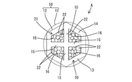
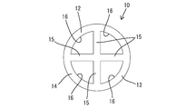
- the rigid conductor 10 includes a cylindrical main body 11 having a circular cross section over the entire length, and a pair of cylindrical end members 12 fixed to the front and rear ends of the cylindrical main body 11.
- the cylindrical main body 11 is an elongated member which constitutes a region of most of the rigid conductor 10 excluding both end portions.
- the cross-sectional shape of the inner periphery of the cylindrical main body 11 is substantially a perfect circle, and no protrusion-like portion or the like is formed on the inner periphery of the cylindrical main body 11.
- the cylindrical end member 12 has a function as the fixing portion 13 which is a connecting means with the coated conductor 20.
- the cylindrical end member 12 is a single component having a cylindrical main body portion 14 and four sliding contact portions 15 projecting radially inward from the inner periphery of the main body portion 14.
- the main body portion 14 in a state before connecting the coated conductor 20 (flexible conductor 21) to the rigid conductor 10 (fixed portion 13) is a cylinder having the same outer diameter and inner diameter as the cylindrical main body 11. It has a shape.
- the cylindrical end member 12 and the cylindrical main body 11 are integrated by coaxially fixing the end surface of the main body portion 14 and the end surface of the cylindrical main body 11 by laser welding or the like.
- the main body portion 14 is plastically deformed to form a substantially regular hexagon (regular polygon) by caulking (see FIG. 2).
- the four sliding contact portions 15 are arranged at equal angular intervals in the circumferential direction of the main body portion 14 There is.
- the number of sliding contact portions 15 is four, but the number of sliding contact portions 15 may be three or less, or five or more.
- each sliding contact portion 15 has a shape linearly extending in the radial direction toward the center of the main body portion 14.
- Each sliding contact portion 15 has a wall shape, and is continuously formed over the entire length of the main body portion 14 (cylindrical terminal member 12).
- the projecting end portions of the four sliding contact portions 15 are connected to form a cross at the central portion of the main body portion 14. Therefore, in the state where the rigid conductor 10 and the coated conductor 20 are not connected, the hollow inside of the cylindrical end member 12 (the fixing portion 13) is partitioned into the four quarter arc shaped connection spaces 16.
- the coated conductor 20 is configured to include a flexible conductor 21 (core wire) formed by twisting a plurality of strands 22 and an insulating coating 23 surrounding the flexible conductor 21 all around.
- the strands 22 are made of aluminum or an aluminum alloy. That is, the flexible conductor 21 of the coated conductor 20 is the same material as the rigid conductor 10.
- the insulating coating 23 is removed and the flexible conductor 21 is exposed.
- the insulating coating 23 is removed at the end of the coated conductor 20 to expose the flexible conductor 21. Then, the strands 22 of the exposed portion of the flexible conductor 21 are untwisted, and the strands 22 are approximately straight and bundled. Next, the flexible conductor 21 is divided into four, and the divided flexible conductors 21 (bundles of the strands 22) are individually inserted into the four connection spaces 16 of the fixed portion 13 (cylindrical end member 12). .
- the wire 22 and the inner wall surface of the connection space 16 come in sliding contact with each other. That is, the wire 22 and the inner circumferential surface of the main body 14 come into sliding contact with each other, and the wire 22 and the sliding contact portion 15 come into sliding contact with each other.
- the oxide film (not shown) on the surface of the wire 22 is scraped off
- the oxide film (not shown) on the inner peripheral surface of the main body 14 is scraped off
- the oxide film on the surface of the sliding portion 15 (Not shown) is scraped off.
- the main body portion 14 is plastically deformed so as to form a regular hexagon from a circular shape.
- the flexible conductor 21 and the fixing portion 13 are firmly fixed. Also in this fixing step, the oxide film on the surface of the wire 22, the oxide film on the inner peripheral surface of the main body portion 14, and the oxide film on the surface of the sliding contact portion 15 are scraped off. As described above, the flexible conductor 21 of the coated conductor 20 and the rigid conductor 10 are connected in a conductive state and in a state in which separation is restricted.
- the conductive member A includes a flexible coated conductor 20 in which a flexible conductor 21 obtained by bundling a plurality of strands 22 and an insulating coating 23 surrounding the flexible conductor 21 are integrated; And a rigid conductor 10. At the end of the rigid conductor 10, a fixing portion 13 which surrounds the flexible conductor 21 and is conductively fixed to the flexible conductor 21 is formed. And the rigid conductor 10 is a form which protruded from the inner periphery of the adhering part 13, and is provided with the sliding contact part 15 which the strand 22 can slide-contact.
- the oxide film is removed by sliding contact with a part of the strands 22 with the inner peripheral surface of the fixing portion 13, Another wire 22 is in sliding contact with the sliding portion 15 to remove the oxide film.
- the rigid conductor 10 is a cylindrical main body 11 constituting an area of substantially the entire length of the rigid conductor 10 excluding the fixing portion 13 and a cylindrical end member disposed at the end of the rigid conductor 10 to constitute the fixing portion 13 It has 12 and. With such a configuration, the sliding contact portion 15 of the rigid conductor 10 can be formed only in the fixing portion 13 in which the flexible conductor 21 is inserted. As a result, it is realized to reduce the weight and material cost of the rigid conductor 10.
- the protruding end portions of the four (plural) sliding contact portions 15 are connected to each other, the protruding length of the sliding contact portion 15 can be secured as long as possible. This makes it possible to increase the number of strands 22 in sliding contact with the sliding contact portion 15.
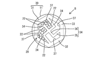
- Example 2 A second embodiment of the present invention will now be described with reference to FIG.
- the conductive member B according to the second embodiment is configured such that the shape of the sliding contact portion 34 of the cylindrical end member 31 (the fixing portion 32) constituting the rigid conductor 30 is different from that of the first embodiment.
- the other parts of the configuration are the same as those of the first embodiment, and thus the same reference numerals are given to the same components, and descriptions of the structures, operations, and effects are omitted.
- the cylindrical end member 31 of the second embodiment is a single component having a cylindrical main body portion 33 and four sliding contact portions 34 projecting radially inward from the inner periphery of the main body portion 33.
- the main body 33 in a state before connecting the coated conductor 20 to the rigid conductor 30 has a cylindrical shape with the same outer diameter and inner diameter as the cylindrical main body.
- the cylindrical end member 31 and the cylindrical portion main body are integrated by coaxially fixing the end surface of the main body portion 33 and the end surface of the cylindrical main body by laser welding or the like.
- the main body 33 is plastically deformed by caulking so as to form a substantially regular hexagon (regular polygon).
- the four sliding contact parts 34 are arranged at equal angular intervals in the circumferential direction of the main body 33 There is.
- the number of sliding contact portions 34 is four, but the number of sliding contact portions 34 may be three or less, or five or more.
- Each sliding contact portion 34 has a bent wall shape, and is continuously formed over the entire length of the main body portion 33 (cylindrical terminal member 31).
- each sliding contact portion 34 has a shape (not shown) bent at an obtuse angle. That is, one sliding contact portion 34 protrudes from the inner periphery of the main body portion 33 toward the center of the main body portion 33 from the peripheral side wall portion 35 that protrudes obliquely with respect to the radial direction and the protruding end edge of the proximal end side wall portion And a central side wall portion 36.
- the peripheral side wall 35 and the central side wall 36 are obliquely connected.
- the four sliding contact portions 34 are connected to each other at the central portion of the main body portion 33. That is, the projecting end portions of the four central side wall portions 36 are connected to form a cruciform.
- the hollow inside of the cylindrical end member 31 (the fixing portion 32) is partitioned into four connection spaces 37.
- each sliding contact portion 34 becomes the peripheral side wall 35 and the central side wall 36 It bends and deforms to reduce the angle with it. Along with this, the volume of each connection space 37 is reduced, so that the main body 33 and the sliding contact portion 34 are in close contact with the bundle of strands 22 so as to be compressed in the radial and circumferential directions.
- the flexible conductor 21 of the coated conductor 20 and the rigid conductor 30 are connected in a conductive state and in a state in which the separation is restricted.
- the protruding length of the sliding contact portion 34 can be secured to a maximum length.
- the sliding contact portion 34 has a bent shape, the number of strands 22 slidingly contacting the sliding contact portion 34 can be increased.
- the sliding contact portion 34 is easily deformed when the fixed portion 32 is plastically deformed and fixed to the flexible conductor 21. Therefore, the shape of the fixing portion 32 (cylindrical terminal member 31) after fixing is stabilized.
- Example 3 A third embodiment of the present invention will now be described with reference to FIG.
- the conductive member C according to the third embodiment is configured such that the shape of the sliding contact portion 44 of the cylindrical end member 41 (the fixing portion 42) constituting the rigid conductor 40 is different from that of the first embodiment.
- the other parts of the configuration are the same as those of the first embodiment, and thus the same reference numerals are given to the same components, and descriptions of the structures, operations, and effects are omitted.
- the cylindrical end member 41 (the fixing portion 42) of the third embodiment has an equal angle in the circumferential direction from the inner periphery of the main portion 43 and the main portion 43 having a circular shape in a state where the rigid conductor 40 and the coated conductor 20 are not connected.
- a plurality of (for example, eight) sliding contacts 44 arranged at intervals.
- Each sliding contact portion 44 has a wall shape linearly projecting radially inward from the inner periphery of the main body portion 43 toward the center.
- the protruding length of the sliding contact portion 44 is set to be smaller than the radius of the circular main portion 43.
- the distance between adjacent sliding contact portions 44 in the circumferential direction is set to be larger than the outer diameter of one strand 22. Accordingly, a plurality of strands 22 are accommodated between the adjacent sliding contacts 44.
- the projecting ends of the sliding contact portion 44 maintain the non-contact state.
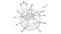
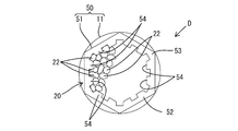
- the conductive member D of the fourth embodiment has a configuration in which the shape of the sliding contact portion 54 of the cylindrical end member 51 (the fixing portion 52) constituting the rigid conductor 50 is different from that of the first embodiment.
- the other parts of the configuration are the same as those of the first embodiment, and thus the same reference numerals are given to the same components, and descriptions of the structures, operations, and effects are omitted.
- the cylindrical end member 51 (the fixing portion 52) of the third embodiment has an equal angle in the circumferential direction from the inner periphery of the main portion 53 and the main portion 53 having a circular shape in a state where the rigid conductor 50 and the coated conductor 20 are not connected.
- a plurality of (for example, 12) sliding contacts 54 arranged at intervals.
- Each sliding contact portion 54 has a rib shape projecting radially inward from the inner periphery of the main body portion 53.
- the projection dimension in the radial direction of each sliding contact portion 54 and the interval between the sliding contact portions 54 adjacent in the circumferential direction are set to substantially the same dimension.
- the protruding dimension of the sliding contact portion 54 is set to be substantially the same as the outer diameter of one strand 22. That is, the number of strands 22 accommodated between the adjacent sliding contacts 54 is only one or two. Therefore, when connecting the rigid conductor 50 and the coated conductor 20, the flexible conductor 21 is held in the cylindrical end member 51 (the fixing portion 52) in a state in which the strands 22 are twisted together (a state in which the strand is not broken). Can be inserted into
- the rigid conductor is constituted by the cylindrical main body and the cylindrical end member, but the rigid conductor is cylindrical over the entire length, and extends from the inner periphery to the entire length of the rigid conductor
- the sliding contact portion may be formed to protrude. According to this configuration, the entire rigid conductor including the sliding contact portion can be manufactured as an integral part only by extrusion molding.
- the sliding contact portion is integrally formed on the inner periphery of the fixing portion (cylindrical end member), but the sliding contact portion is formed as a component separate from the fixing portion. May be fixed to the inner periphery of the fixing portion.
- the rigid conductor is made of aluminum or an aluminum alloy, but the material of the rigid conductor may be a material other than aluminum or aluminum alloy (copper, copper alloy, etc.).
- the flexible conductor is made of aluminum or aluminum alloy, but the material of the flexible conductor may be other than aluminum or aluminum alloy (copper, copper alloy, etc.).
- the rigid conductor and the flexible conductor of the coated conductor are made of the same material, the rigid conductor and the flexible conductor may be made of different materials.
- at least one side of the wire is accommodated between the sliding contact portions adjacent in the circumferential direction.
- the knurling process may be applied to a plurality of sliding contact portions arranged at a pitch smaller than the outer diameter of the wire in the circumferential direction.
- the flexible conductor can be inserted into the fixed portion without untwisting the strands.
- the cross-sectional shape of the main body portion and the cylindrical main body is circular in a state before connecting the coated conductor (flexible conductor) to the rigid conductor (fixed portion).
- the cross-sectional shape of the tubular body may be non-circular.
- the rigid conductor is in the form of a hollow pipe, the area of the rigid conductor other than the fixed portion (cylindrical end member) may be a solid rod shape.
- the oxide film is removed in both the step of inserting the flexible conductor into the fixing portion and the step of fixing the flexible conductor to the fixing portion. The process may be performed only in one of the insertion process and the fixation process.
- A, B, C, D conductive member 10, 30, 40: rigid conductor 11: cylindrical main body 12, 31, 41, 51: cylindrical end member 13, 32, 42, 52: fixed part 15, 34, 44 , 54 ... sliding contact portion 20 ... coated conductor 21 ... flexible conductor 22 ... strand 23 ... insulation coating
Landscapes
- Engineering & Computer Science (AREA)
- Manufacturing & Machinery (AREA)
- Connections Effected By Soldering, Adhesion, Or Permanent Deformation (AREA)
- Insulated Conductors (AREA)
Priority Applications (2)
| Application Number | Priority Date | Filing Date | Title |
|---|---|---|---|
| CN201780025322.3A CN109075461B (zh) | 2016-04-25 | 2017-04-11 | 导电部件 |
| US16/095,834 US10826201B2 (en) | 2016-04-25 | 2017-04-11 | Conductive member |
Applications Claiming Priority (2)
| Application Number | Priority Date | Filing Date | Title |
|---|---|---|---|
| JP2016-086806 | 2016-04-25 | ||
| JP2016086806A JP6610411B2 (ja) | 2016-04-25 | 2016-04-25 | 導電部材 |
Publications (1)
| Publication Number | Publication Date |
|---|---|
| WO2017187954A1 true WO2017187954A1 (ja) | 2017-11-02 |
Family
ID=60161532
Family Applications (1)
| Application Number | Title | Priority Date | Filing Date |
|---|---|---|---|
| PCT/JP2017/014741 Ceased WO2017187954A1 (ja) | 2016-04-25 | 2017-04-11 | 導電部材 |
Country Status (4)
| Country | Link |
|---|---|
| US (1) | US10826201B2 (enExample) |
| JP (1) | JP6610411B2 (enExample) |
| CN (1) | CN109075461B (enExample) |
| WO (1) | WO2017187954A1 (enExample) |
Families Citing this family (3)
| Publication number | Priority date | Publication date | Assignee | Title |
|---|---|---|---|---|
| CN110323579A (zh) * | 2018-03-28 | 2019-10-11 | 佛山市顺德区美的电热电器制造有限公司 | 接线端子连接结构、线圈盘以及电磁加热烹饪装置 |
| JP2019204633A (ja) * | 2018-05-22 | 2019-11-28 | 矢崎総業株式会社 | 接続部材 |
| EP4708577A1 (en) * | 2024-09-10 | 2026-03-11 | Prysmian S.p.A. | Electrical cable mechanical connector and method of connecting an electrical cable to a mechanical connector |
Citations (5)
| Publication number | Priority date | Publication date | Assignee | Title |
|---|---|---|---|---|
| JPS361124Y1 (enExample) * | 1958-03-17 | 1961-01-23 | ||
| JP2010146739A (ja) * | 2008-12-16 | 2010-07-01 | Sumitomo Wiring Syst Ltd | 電線接続スリーブ、電線接続スリーブの製造方法、電線接続スリーブが予め圧着されたリペア電線、および電線の接続方法 |
| JP2010176886A (ja) * | 2009-01-27 | 2010-08-12 | Sumitomo Wiring Syst Ltd | 電線接続スリーブ、リペア電線、電線接続スリーブの製造方法、および電線の接続方法 |
| JP2015088251A (ja) * | 2013-10-28 | 2015-05-07 | 矢崎総業株式会社 | 回路導体、接続構造、及び回路導体の製造方法 |
| JP2016018672A (ja) * | 2014-07-08 | 2016-02-01 | 矢崎総業株式会社 | 端子金具、及び、端子金具付き電線 |
Family Cites Families (46)
| Publication number | Priority date | Publication date | Assignee | Title |
|---|---|---|---|---|
| US1575994A (en) * | 1923-11-09 | 1926-03-09 | Electron Relay Company | Lead-in wire and gas-tight seal and method of making the same |
| US2008227A (en) * | 1933-08-12 | 1935-07-16 | Reilly Frank Ward | Attachement for wire strands |
| US2640095A (en) * | 1949-02-08 | 1953-05-26 | Western Electric Co | Coaxial cable splice and methods of making it |
| US2815497A (en) * | 1953-04-23 | 1957-12-03 | Amp Inc | Connector for aluminum wire |
| US2868863A (en) * | 1954-01-05 | 1959-01-13 | Kaiser Aluminium Chem Corp | Aluminum to copper connection |
| US2937228A (en) * | 1958-12-29 | 1960-05-17 | Robinson Machine Works Inc | Coaxial cable splice |
| US3447821A (en) * | 1965-07-16 | 1969-06-03 | Michael Bochory | Fastening mechanism |
| US3568130A (en) * | 1969-04-07 | 1971-03-02 | Kdi Sealtron Corp | Electrical connector for aluminum cable |
| AU6695174A (en) * | 1974-03-21 | 1975-09-25 | Amp Inc | Electrical connectors |
| US3990143A (en) * | 1974-06-21 | 1976-11-09 | Amp Incorporated | Method for terminating an electrical wire in an open barrel terminal |
| US3996417A (en) * | 1974-09-12 | 1976-12-07 | Aluminum Company Of America | Cable core grip, electrical cable and connector assembly, and electrical connector kit |
| US3931726A (en) * | 1975-01-21 | 1976-01-13 | Amp Incorporated | Propellant-driven device for crimping large size wire and terminals |
| US4018976A (en) * | 1976-04-15 | 1977-04-19 | Grove Earl I | Kickless resistance welding cable and method of making the same |
| US4086427A (en) * | 1976-06-08 | 1978-04-25 | Westinghouse Electric Corporation | Common shield-terminating connection in shielded wire bundle |
| US4199653A (en) * | 1978-06-14 | 1980-04-22 | Watteredge-Uniflex, Inc. | Termination for alternate polarity resistance welding cable |
| US4556265A (en) * | 1981-06-29 | 1985-12-03 | Rca Corporation | RF Coaxial-strip line connector |
| US4442182A (en) * | 1982-05-26 | 1984-04-10 | Teledyne Penn-Union | One-piece, composite electrical connector |
| US4828516A (en) * | 1983-12-30 | 1989-05-09 | Amp Incorporated | Crimped electrical connection and crimping dies therefore |
| EP0318844A1 (en) * | 1987-11-30 | 1989-06-07 | Tsuyoshi Mukai | Conductor-connecting terminal implement |
| JP3673527B2 (ja) * | 1993-04-30 | 2005-07-20 | 矢崎総業株式会社 | シールド電線接続用端子 |
| US5526549A (en) * | 1993-07-01 | 1996-06-18 | Sumitomo Wiring Systems, Ltd. | Grommet |
| US5527994A (en) * | 1994-05-31 | 1996-06-18 | Kasper; James J. | Water cooled kickless cable and method |
| US5749756A (en) * | 1995-10-27 | 1998-05-12 | The Whitaker Corporation | Sealed corrosion-proof crimped terminal of splice |
| US5847320A (en) * | 1997-09-30 | 1998-12-08 | Fisher; Ivan B. | Solderless wire splicing device and method |
| US6160216A (en) * | 1999-01-12 | 2000-12-12 | Raytheon Company | Wiring harness shield splitter |
| US6677529B1 (en) * | 1999-02-05 | 2004-01-13 | John E. Endacott | Wire connector |
| JP2001357903A (ja) * | 2000-06-13 | 2001-12-26 | Sumitomo Wiring Syst Ltd | 電線間接続用の圧着端子 |
| US7223112B2 (en) * | 2004-01-09 | 2007-05-29 | Hubbell Incorporated | Communication connector to optimize crosstalk |
| US6995316B1 (en) * | 2004-08-04 | 2006-02-07 | Tyco Electronics Canada, Ltd. | Overmolded wire sealing assembly |
| US7256348B1 (en) * | 2006-02-22 | 2007-08-14 | Endacott John E | Step-down in-line butt connector |
| KR101361389B1 (ko) * | 2006-12-28 | 2014-02-10 | 후루카와 덴키 고교 가부시키가이샤 | 하니스 접속부재 |
| US7600721B2 (en) * | 2007-07-23 | 2009-10-13 | Panduit Corp. | Network cable bundling tool |
| CA2715398C (en) * | 2008-02-21 | 2016-05-03 | Mark L. Melni | Electrical connectors and methods of manufacturing and using same |
| JP5739442B2 (ja) * | 2009-11-11 | 2015-06-24 | ボレアリス エージー | ケーブルおよびその製造法 |
| JP4897058B2 (ja) * | 2010-01-14 | 2012-03-14 | 株式会社オートネットワーク技術研究所 | シールド導電路 |
| US7972183B1 (en) * | 2010-03-19 | 2011-07-05 | Commscope, Inc. Of North Carolina | Sled that reduces the next variations between modular plugs |
| JP5740146B2 (ja) * | 2010-12-10 | 2015-06-24 | 矢崎総業株式会社 | ワイヤハーネス |
| JP5720362B2 (ja) * | 2011-03-28 | 2015-05-20 | 住友電装株式会社 | 仕切り付きシールドパイプ |
| US8585447B2 (en) * | 2011-08-17 | 2013-11-19 | Delphi Technologies, Inc. | Electrically-conducting contact element with an aperture with an internal surface having a groove with sharp edges |
| US8205786B1 (en) * | 2011-10-03 | 2012-06-26 | Honeywell International Inc. | Electromagnetic coil assemblies including aluminum wire splice connectors, aluminum wire splice connectors, and associated methods |
| EP2915171B1 (en) * | 2012-10-31 | 2019-10-09 | Aptiv Technologies Limited | Device and method for splicing shielded wire cables |
| EP3569648B1 (en) * | 2013-12-19 | 2020-09-30 | Borealis AG | Power cable |
| JP6278272B2 (ja) * | 2014-09-05 | 2018-02-14 | 住友電装株式会社 | 導電線及びその配索構造 |
| JP6040299B1 (ja) * | 2015-09-11 | 2016-12-07 | 住友電装株式会社 | シールド導電路 |
| US9985362B2 (en) * | 2015-10-22 | 2018-05-29 | Carlisle Interconnect Technologies, Inc. | Arc resistant power terminal |
| JP6690587B2 (ja) * | 2017-03-16 | 2020-04-28 | 住友電装株式会社 | 電線配索部材及び電線配索構造 |
-
2016
- 2016-04-25 JP JP2016086806A patent/JP6610411B2/ja not_active Expired - Fee Related
-
2017
- 2017-04-11 CN CN201780025322.3A patent/CN109075461B/zh not_active Expired - Fee Related
- 2017-04-11 US US16/095,834 patent/US10826201B2/en not_active Expired - Fee Related
- 2017-04-11 WO PCT/JP2017/014741 patent/WO2017187954A1/ja not_active Ceased
Patent Citations (5)
| Publication number | Priority date | Publication date | Assignee | Title |
|---|---|---|---|---|
| JPS361124Y1 (enExample) * | 1958-03-17 | 1961-01-23 | ||
| JP2010146739A (ja) * | 2008-12-16 | 2010-07-01 | Sumitomo Wiring Syst Ltd | 電線接続スリーブ、電線接続スリーブの製造方法、電線接続スリーブが予め圧着されたリペア電線、および電線の接続方法 |
| JP2010176886A (ja) * | 2009-01-27 | 2010-08-12 | Sumitomo Wiring Syst Ltd | 電線接続スリーブ、リペア電線、電線接続スリーブの製造方法、および電線の接続方法 |
| JP2015088251A (ja) * | 2013-10-28 | 2015-05-07 | 矢崎総業株式会社 | 回路導体、接続構造、及び回路導体の製造方法 |
| JP2016018672A (ja) * | 2014-07-08 | 2016-02-01 | 矢崎総業株式会社 | 端子金具、及び、端子金具付き電線 |
Also Published As
| Publication number | Publication date |
|---|---|
| CN109075461A (zh) | 2018-12-21 |
| JP6610411B2 (ja) | 2019-11-27 |
| CN109075461B (zh) | 2020-11-06 |
| US10826201B2 (en) | 2020-11-03 |
| JP2017199461A (ja) | 2017-11-02 |
| US20190288407A1 (en) | 2019-09-19 |
Similar Documents
| Publication | Publication Date | Title |
|---|---|---|
| JP5945155B2 (ja) | 電線の外部導体端子の接続構造 | |
| US9325213B2 (en) | Motor connecting member and motor device | |
| JP6646874B2 (ja) | プロテクタ及びワイヤハーネス | |
| JP6471909B2 (ja) | ワイヤハーネス | |
| US20150107896A1 (en) | Coaxial cable having end terminal and method of manufacturing the same | |
| WO2017187954A1 (ja) | 導電部材 | |
| JP2010176886A (ja) | 電線接続スリーブ、リペア電線、電線接続スリーブの製造方法、および電線の接続方法 | |
| US12243665B2 (en) | Wire harness | |
| US20180131167A1 (en) | Single-core wire and wire harness | |
| JP6708353B2 (ja) | シールド端末処理方法及びワイヤハーネス | |
| JP6471910B2 (ja) | ワイヤハーネス | |
| CN108886205B (zh) | 导体的连接结构以及线束 | |
| JP6720929B2 (ja) | 導電路及びワイヤハーネス | |
| JP4503458B2 (ja) | シールド電線のアース接続具およびアース接続方法 | |
| WO2015053182A1 (ja) | 圧着端子 | |
| JP6593644B2 (ja) | 電線の接続構造およびワイヤハーネス | |
| JP2023122883A (ja) | シールド電線及びシールド電線の製造装置 | |
| JP5885346B2 (ja) | 圧着端子付きアルミニウム電線および圧着端子付きアルミニウム電線の製造方法 | |
| JP2021061208A (ja) | 電線接続構造 | |
| US11139591B2 (en) | Conductive member | |
| JP2024059340A (ja) | シールド電線、及びコネクタ | |
| JP2020053252A (ja) | 端子付電線及びその製造方法 | |
| JP6551977B2 (ja) | ワイヤハーネス | |
| JP6545010B2 (ja) | 端子 | |
| WO2021124897A1 (ja) | 圧着端子、及び端子付き電線 |
Legal Events
| Date | Code | Title | Description |
|---|---|---|---|
| NENP | Non-entry into the national phase |
Ref country code: DE |
|
| 121 | Ep: the epo has been informed by wipo that ep was designated in this application |
Ref document number: 17789241 Country of ref document: EP Kind code of ref document: A1 |
|
| 122 | Ep: pct application non-entry in european phase |
Ref document number: 17789241 Country of ref document: EP Kind code of ref document: A1 |