WO2017187845A1 - 眼球の光計測システム及び眼球用の装着部材 - Google Patents
眼球の光計測システム及び眼球用の装着部材 Download PDFInfo
- Publication number
- WO2017187845A1 WO2017187845A1 PCT/JP2017/011237 JP2017011237W WO2017187845A1 WO 2017187845 A1 WO2017187845 A1 WO 2017187845A1 JP 2017011237 W JP2017011237 W JP 2017011237W WO 2017187845 A1 WO2017187845 A1 WO 2017187845A1
- Authority
- WO
- WIPO (PCT)
- Prior art keywords
- light
- eyeball
- reflecting portion
- reflecting
- contact member
- Prior art date
- Legal status (The legal status is an assumption and is not a legal conclusion. Google has not performed a legal analysis and makes no representation as to the accuracy of the status listed.)
- Ceased
Links
Images












Classifications
-
- A—HUMAN NECESSITIES
- A61—MEDICAL OR VETERINARY SCIENCE; HYGIENE
- A61B—DIAGNOSIS; SURGERY; IDENTIFICATION
- A61B3/00—Apparatus for testing the eyes; Instruments for examining the eyes
- A61B3/10—Objective types, i.e. instruments for examining the eyes independent of the patients' perceptions or reactions
- A61B3/117—Objective types, i.e. instruments for examining the eyes independent of the patients' perceptions or reactions for examining the anterior chamber or the anterior chamber angle, e.g. gonioscopes
-
- A—HUMAN NECESSITIES
- A61—MEDICAL OR VETERINARY SCIENCE; HYGIENE
- A61B—DIAGNOSIS; SURGERY; IDENTIFICATION
- A61B3/00—Apparatus for testing the eyes; Instruments for examining the eyes
- A61B3/10—Objective types, i.e. instruments for examining the eyes independent of the patients' perceptions or reactions
- A61B3/13—Ophthalmic microscopes
Definitions
- the present invention relates to an optical measurement system for an eyeball and a mounting member for the eyeball.
- Patent Document 1 in an apparatus for measuring glucose concentration using an eyeball, a light emitting means and a light receiving means are arranged behind the apex of the cornea, and light is emitted and received across the anterior chamber.
- An optical measuring device having a configuration is disclosed.
- At least one embodiment of the present invention is an eyeball in which it is easy to secure a space for arranging a light emitting part or a light receiving part as compared with a configuration in which a light emitting part and a light receiving part are arranged behind the top of the cornea.
- An object of the present invention is to provide an optical measurement system and a mounting member for an eyeball.
- a first reflecting unit that reflects light incident from the front of the eyeball so as to cross the anterior chamber, and the light that has crossed the anterior chamber is transmitted to the front of the eyeball.
- An attachment member that is attached to the spherical surface of the eye, a light emitting portion that emits light toward the anterior chamber, and light that has crossed the anterior chamber And an optical measurement device that is disposed in front of the eyeball in a state of being separated from the mounting member.
- the mounting member may have a shape along the cornea of the eyeball and may be mounted on the cornea.
- At least one of the first reflecting portion and the second reflecting portion included in the mounting member may be formed of a metal surface. Good.
- the mounting member includes the first reflecting portion, and the first reflecting portion is the first reflecting portion. It may be formed in a size that includes the beam diameter of the light incident on.
- at least one of the first reflecting portion and the second reflecting portion included in the mounting member includes a plurality of reflecting surfaces. It may be comprised.
- the mounting member may include the first reflecting portion and the second reflecting portion.
- the reflective portion may have a larger area than the first reflective portion.
- at least one of the first reflecting portion and the second reflecting portion included in the mounting member has an arc shape with the center of the mounting member as an axis. You may have a shape.
- the mounting member may include the first reflecting portion and the second reflecting portion. A circular continuous reflecting surface provided on the first and second reflecting portions may function as the first reflecting portion and the second reflecting portion.
- the mounting member when the mounting member is mounted on an eyeball, a predetermined orientation in a rotation direction about the center of the mounting member The shape arrange
- positioned may be sufficient.
- the mounting member has a predetermined incident area on the mounting member on which the light emitted from the light emitting unit is incident. Other regions may have a light shielding region that blocks the light from reaching the eyeball.
- a first reflecting unit that reflects light incident from the front of the eyeball so as to cross the anterior chamber, and light that has crossed the anterior chamber to the front of the eyeball.
- the light emitting unit includes at least one of a second reflecting unit that reflects and is used together with a light emitting unit that emits light toward the anterior chamber and a light receiving unit that receives light crossing the anterior chamber. And a mounting member for an eyeball that is mounted on the eyeball surface in a state separated from the light receiving unit.
- the eyeball optical measurement system described in [1] it is possible to secure a space for arranging the light emitting means or the light receiving means, as compared with the configuration in which the light emitting part and the light receiving part are arranged behind the top of the cornea. It becomes easy.
- the optical measurement system for an eyeball described in [2] the eyeball is easily mounted on the cornea as compared with a shape not along the cornea.
- the optical measurement system for an eyeball described in [3] it is easy to increase the reflectance as compared with a reflection surface made of a resin material.
- the optical measurement system for an eyeball described in [4] more light can be reflected toward the anterior chamber as compared with a case where the reflecting portion is smaller than the beam diameter.
- the optical measurement system for an eyeball described in [5] it is easy to increase the area of the reflection surface along the shape of the mounting member, as compared with the case where it is configured by a single reflection surface.
- the eyeball optical measurement system described in [6] light can easily enter the second reflecting portion even when the angle of the light reflected by the first reflecting portion varies.
- the optical measurement system for an eyeball described in [7] it is possible to prevent the incident position of the light from deviating from the reflecting portion even when the mounting member rotates on the eyeball, as compared with a configuration that is not arcuate. Is done.
- the mounting member rotates on the eyeball as compared with the configuration in which the first reflecting portion and the second reflecting portion are provided separately. However, it is suppressed that the incident position of light deviates from the reflection part.
- the eyeball optical measurement system described in [9] it is easy to maintain the mounting member in a predetermined orientation on the eyeball.
- the eyeball optical measurement system of [10] when the light emitted from the light emitting part deviates from a predetermined incident region on the mounting member, an unintended eyeball region is irradiated. Is suppressed.
- the eyeball mounting member described in [11] it is easy to secure a space for arranging the light emitting part or the light receiving part as compared with the configuration in which the light emitting part and the light receiving part are arranged behind the top of the cornea. become.
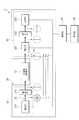
- FIG. 1A and 1B are diagrams illustrating an example of the configuration of an optical measurement system 1 for an eyeball to which the first embodiment is applied.
- FIG. 1A is a front view of the eyeball 10 and the optical measurement system 1 of the eyeball
- FIG. 1B is a front view of the contact member 30 with a reflecting portion attached to the eyeball 10.
- a front view is a figure of the contact member 30 with a reflection part at the time of seeing from + y direction shown to FIG. 1B.
- 1A is a cross-sectional view taken along line IA-IA in FIG. 1B.
- the eyeball optical measurement system 1 includes a light measurement system 20 that includes a light emitting system 21 that emits light toward the eyeball 10 and a light receiving system 22 that receives light from the eyeball 10, and a cornea (eyeball surface) of the eyeball 10. ) And a contact member 30 with a reflection portion as an example of a mounting member (eyeball mounting member).
- the light emitting system 21 in the optical measuring device 20 is an example of a light emitting unit
- the light receiving system 22 is an example of a light receiving unit.
- the human eyeball 10 has a substantially spherical outer shape and has a glass body 11 in the center.
- a crystalline lens 12 serving as a lens is embedded in a part of the glass body 11.
- the peripheral portion of the crystalline lens 12 is surrounded by an iris, and the center is the pupil 15.
- the glass body 11 is covered with a retina 16 except for a portion in contact with the crystalline lens 12.
- the anterior chamber 13 is filled with aqueous humor.
- the + x direction is the right direction of the face (eyeball 10)
- the -x direction is the leftward direction of the face (eyeball 10)
- the + y direction is the front direction (front, near side) of the face (eyeball 10).
- the ⁇ y direction is the backward direction (backward and back side) of the face (eyeball 10)
- the + z direction is the upward direction of the face (eyeball 10)
- the ⁇ z direction is the downward direction of the face (eyeball 10).
- 1A is a view of the eyeball 10 as viewed from below.
- the optical measurement device 20 includes a control unit 23 and a calculation unit 24 in addition to the light emitting system 21 and the light receiving system 22.
- the light emitting system 21 includes a light emitting unit 211 that emits light and a polarizer 212 that extracts predetermined linearly polarized light from incident light.
- the light receiving system 22 receives a compensator 221 that compensates for the rotation angle of linearly polarized light whose oscillation direction is rotated by aqueous humor in the anterior chamber 13, and an analyzer 222 that passes light having a predetermined polarization angle.
- a light receiving unit 223 that converts light intensity into an electric signal.
- the optical measuring device 20 will be described in detail later.
- the contact member 30 with a reflecting portion is a member for an eyeball similar to a so-called contact lens, and is attached to the surface (eyeball surface) of the cornea 14 in the eyeball 10.
- the attachment of the contact member 30 with a reflection portion to the surface (eye spherical surface) of the cornea 14 in the eyeball 10 is hereinafter expressed as the contact member 30 with a reflection portion being attached to the eyeball 10.
- the contact member 30 with a reflecting portion includes a base 31 and two reflecting portions 33 and 34.
- the two reflecting portions 33 and 34 are provided at positions where the anterior chamber 13 is sandwiched when the contact member 30 with the reflecting portion is mounted on the surface of the eyeball 10.
- the reflection parts 33 and 34 are provided side by side in the x direction.
- the reflection unit 33 reflects the light emitted from the light emitting system 21 of the optical measurement device 20 so as to cross the aqueous humor of the anterior chamber 13.
- the reflection unit 34 reflects the light that has crossed the aqueous humor of the anterior chamber 13 so as to enter the light receiving system 22 of the optical measurement device 20.
- the reflection unit 33 is an example of a first reflection unit
- the reflection unit 34 is an example of a second reflection unit.
- the reflection parts 33 and 34 are comprised by a plane mirror, for example.
- the reflection portions 33 and 34 are arranged on a line that becomes the diameter of the contact member 30 with a reflection portion, but may be arranged on a line parallel to the line that becomes the diameter.
- the reflecting portions 33 and 34 are arranged on a line that is shifted to the side closer to the lower eyelid than on the diameter line. Should be placed. In this way, even when it is difficult to open the upper eyelid, it is easy to secure the optical path 25 that crosses the aqueous humor of the anterior chamber 13.
- the reflection portions 33 and 34 of the contact member 30 with a reflection portion may be provided so as to sandwich the anterior chamber 13 in the vertical direction (z direction) with respect to the eyeball 10. Furthermore, the anterior chamber 13 may be sandwiched with respect to the eyeball 10 in an oblique direction (from the upper left to the lower right or from the upper right to the lower left). If the reflection parts 33 and 34 of the contact member 30 with a reflection part are provided in the left-right direction or the oblique direction of the eyeball 10, it is difficult to be affected by eyelashes.
- “crossing” the aqueous humor means any route that passes through the aqueous humor in the vertical direction, the horizontal direction, and the diagonal direction of the eyeball 10. And a path through which the aqueous humor passes from the near side to the far side of the eyeball 10 is not included.
- the contact member 30 with a reflective part will be described in detail later.
- the left and right direction (+ x direction and ⁇ x direction) of the eyeball 10 that is, the rear side (back side) of the top of the cornea 14 (tip portion in the y direction).
- the light emitting system 21 and the light receiving system 22 are arranged in the above.
- the skin around the eyeball 10 such as the nose gets in the way, and it is difficult to secure a space for arranging the light emitting system 21 or the light receiving system 22.
- the light emitting system 21 or the light receiving system 22 can be arranged with a space secured, the light emitting system 21 or the light receiving system 22 is arranged so as to easily come into contact with the eyeball 10.
- the light emitting system 21 and the light receiving system 22 are provided in front of the eyeball 10 (front side) by attaching the contact member 30 with a reflecting portion to the eyeball 10. That is, it is easy to secure a space for providing the light emitting system 21 and the light receiving system 22. Further, by separating the light emitting system 21 or the light receiving system 22 from the eyeball 10, the possibility that the light emitting system 21 or the light receiving system 22 contacts the eyeball 10 is reduced.
- the optical measuring device 20 is physically separated from the contact member 30 with a reflecting portion, and is positioned in front of the eyeball 10 on which the contact member 30 with a reflecting portion is mounted at the time of measurement.
- the optical measurement device 20 can be configured, for example, as a head mount type or a spectacle type.
- the light emitting system 21 and the light receiving system 22 are provided at a position where the optical path 25 between the optical measuring device 20 and the contact member 30 with the reflecting portion becomes an optical path along the x direction as shown in FIG. 1B.
- the light emitting system 21 and the light receiving system 22 are provided at positions that overlap with the reflecting portion 33 and the reflecting portion 34 of the contact member 30 with the reflecting portion.
- the light path does not necessarily have to be along the x direction, and the light emitting system 21 and the light receiving system 22 may be provided at a position that is an oblique light path with respect to the x direction.
- the light emitting system 21 and the light receiving system 22 may be configured in reverse.
- the aqueous humor in the anterior chamber 13 which is almost the same component as serum contains protein, glucose, ascorbic acid and the like. It is known that there is a correlation between the glucose concentration in blood and the glucose concentration in aqueous humor. Further, in the aqueous humor, there is no cellular material in the blood, and the influence of light scattering is small. Proteins, glucose, ascorbic acid and the like contained in aqueous humor are optically active substances and have optical activity. That is, the aqueous humor is advantageous as a site for optically measuring the concentration of glucose or the like using optical rotation.
- FIG. 2 is a diagram for explaining a method of measuring the rotation angle (optical rotation) of polarized light by the optically active substance contained in the aqueous humor in the anterior chamber 13 by the optical measurement system 1 of the eyeball.
- the description of the contact member 30 with a reflecting portion is omitted assuming that the optical path 25 is not bent (the optical path 25 is a straight line).
- the light emitting unit 211 and the polarizer 212 of the light emitting system 21 in the optical measuring device 20 the anterior chamber 13 in the eyeball 10, and the compensator 221 of the light receiving system 22 in the optical measuring device 20.
- the analyzer 222 and the light receiving unit 223 the state of polarized light viewed from the traveling direction of light is indicated by an arrow in a circle.
- the light emitting unit 211 may be a light source having a wide wavelength width such as a light emitting diode (LED) or a lamp, or may be a light source having a narrow wavelength width such as a laser. It is preferable that the wavelength width is narrow. Further, the light emitting unit 211 may emit light having at least two wavelengths.
- LED light emitting diode
- a lamp or may be a light source having a narrow wavelength width such as a laser. It is preferable that the wavelength width is narrow. Further, the light emitting unit 211 may emit light having at least two wavelengths.
- the polarizer 212 is, for example, a Nicol prism or the like, and allows linearly polarized light having a predetermined vibration direction to pass among incident light.
- the compensator 221 is a magneto-optical element such as a Faraday element using garnet or the like, and rotates linearly polarized light by a magnetic field.
- the analyzer 222 is a member similar to the polarizer 212 and allows linearly polarized light having a predetermined vibration direction to pass therethrough.
- the light receiving unit 223 is a light receiving element such as a silicon diode, and outputs a deelectric signal corresponding to the intensity of light.
- the control unit 23 controls the light emitting system 21 and the light receiving system 22 in the optical measurement device 20 to obtain measurement data regarding the characteristics of the aqueous humor of the anterior chamber 13 and transmit the measurement data to the calculation unit 24.
- the calculation unit 24 receives the measurement data from the control unit 23 and calculates the characteristics of the aqueous humor.
- the light emitting unit 211 emits randomly polarized light.
- the polarizer 212 passes a predetermined linearly polarized light.
- FIG. 2 as an example, it is assumed that linearly polarized light that vibrates in a direction parallel to the paper surface passes through the polarizer 212.
- the direction of vibration of the linearly polarized light that has passed through the polarizer 212 is rotated by the optically active substance contained in the aqueous humor in the anterior chamber 13.
- ⁇ M optical rotation ⁇ M
- the vibration direction rotated by the optically active substance contained in the aqueous humor in the anterior chamber 13 is restored.
- the linearly polarized light that has passed through the analyzer 222 is received by the light receiving unit 223 and converted into an output signal corresponding to the intensity of the light.
- the optical measurement device 20 including the light emitting unit 211, the polarizer 212, the compensator 221, the analyzer 222, and the light receiving unit 223, the light receiving unit 223.
- the compensator 221 and the analyzer 222 are set so that the output signal is minimized.
- FIG. 2 in a state where light does not pass through the anterior chamber 13, the vibration direction of linearly polarized light that has passed through the polarizer 212 is orthogonal to the vibration direction of linearly polarized light that has passed through the analyzer 222.
- FIG. 2 in a state where light does not pass through the anterior chamber 13, the vibration direction of linearly polarized light that has passed through the polarizer 212 is orthogonal to the vibration direction of linearly polarized light that has passed through the analyzer 222.
- the vibration directions of the linearly polarized light before passing through the polarizer 212 and the analyzer 222 are both parallel to the paper surface.
- the vibration direction of the linearly polarized light before passing through the analyzer 222 may be inclined from a plane parallel to the paper surface. That is, the compensator 221 and the analyzer 222 are set so that the output signal of the light receiving unit 223 is minimized in a state where light does not pass through the anterior chamber 13.
- the vibration direction of the linearly polarized light is rotated by the optically active substance contained in the aqueous humor in the anterior chamber 13. For this reason, the output signal from the light receiving unit 223 deviates from the minimum value. Therefore, the magnetic field applied to the compensator 221 is set so that the output signal from the light receiving unit 223 is minimized. That is, the vibration direction of the linearly polarized light is rotated by the compensator 221 so as to be orthogonal to the vibration direction of the linearly polarized light passing through the analyzer 222.
- the vibration direction of the linearly polarized light rotated by the compensator 221 corresponds to the optical rotation ⁇ M generated by the optically active substance contained in the aqueous humor. Since the relationship between the magnitude of the magnetic field applied to the compensator 221 and the angle of the vibration direction of the rotated linearly polarized light is known in advance, the optical rotation ⁇ M can be determined from the magnitude of the magnetic field applied to the compensator 221. . Although described an example using compensator 221 as a method for determining the optical rotation alpha M, may be obtained optical rotation alpha M except by compensator 221.
- 1A and 2 show the orthogonal polarizer method (which uses the compensator 221), which is the most basic measurement method for measuring the rotation angle (rotation angle ⁇ M ) of the vibration direction of linearly polarized light.
- Other measurement methods such as a rotation analyzer method, a Faraday modulation method, and an optical delay modulation method may be applied.
- wavelengths ⁇ (wavelengths ⁇ 1 , ⁇ 2 , ⁇ 3 ,...) Is incident on the aqueous humor of the anterior chamber 13 from the light emitting unit 211, and the optical rotation ⁇ M is applied to each.
- Optical rotations ⁇ M1 , ⁇ M2 , ⁇ M3 ,...) Are obtained.
- a set of the wavelength ⁇ and the optical rotation ⁇ M is taken into the calculation unit 24, and the concentration of the optically active substance to be obtained is calculated.
- the aqueous humor contains a plurality of optically active substances as described above. Therefore, the measured optical rotation ⁇ M is the sum of the optical rotation ⁇ by each of the plurality of optically active substances. Therefore, it is necessary to calculate the concentration of the optically active substance to be obtained from the measured optical rotation ⁇ M.
- the calculation of the concentration of the optically active substance to be obtained may be performed by using a known method as disclosed in, for example, Japanese Patent Application Laid-Open No. 09-138231, and will not be described.
- FIG. 3A, 3B, and 3C are cross-sectional views illustrating the reflecting portions 33 and 34 of the contact member 30 with a reflecting portion in the optical measurement system 1 for an eyeball according to the first embodiment.
- FIG. 3A shows an unsealed reflecting portion 33
- FIG. 3B shows a reflecting portion 33 whose surface is sealed flat
- FIG. 3C shows a reflecting portion 33 sealed with a surface perpendicular to incident light.
- 3A, 3B, and 3C show the reflective portion 33 shown in FIG. 1A, the same applies to the reflective portion 34.
- FIG. 3A, 3B, and 3C show the reflective portion 33 shown in FIG. 1A, the same applies to the reflective portion 34.
- the contact member 30 with a reflective portion includes the base 31 and the reflective portions 33 and 34 as described above.
- the base 31 has a substantially circular outer shape, a concave shape on the inside, and a convex shape on the outside so that it can follow the cornea 14 of the eyeball 10.
- the base 31 is, for example, a resin such as polyhydroxyethyl methacrylate, polymethyl methacrylate, a silicone copolymer, or a fluorine-containing compound.
- the refractive index of the base 31 is close to the refractive index of the aqueous humor of the anterior chamber 13, the cornea 14, etc. in the eyeball 10, refraction at the interface between the reflective contact member 30 and the eyeball 10 is suppressed, Setting of the optical path 25 is facilitated.
- the base 31 does not have to be circular, and may have another shape such as a rectangle as long as it can be attached to the cornea 14.
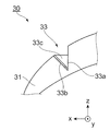
- a mirror 33 b as a reflecting surface is provided in a notch portion 33 a provided in the base 31.
- the notch 33a is not sealed (embedded), and the mirror 33b is exposed.
- the mirror 33b may be configured by utilizing reflection due to a difference in refractive index between the air and the base 31 made of resin, and may be a metal material such as gold or aluminum, or a dielectric multilayer film. You may comprise using etc.
- a metal material metal surface
- the mirror 33b is a part of the notch 33a of the base 31.
- the contact member 30 with a reflecting portion in FIG. 3B has a notch 33a formed by a sealing member 33c made of a material having a refractive index similar to that of the base 31 after the mirror 33b is provided in the notch 33a provided in the base 31. Is sealed (embedded). The surface of the reflection member contact member 30 is smoothly sealed (configured) by the sealing member 33c. Therefore, it is possible to prevent dust from entering the notch 33a. In this case, since it is difficult to use the refractive index difference between air and the base 31 for the mirror 33b, it is preferable to use a metal material or a dielectric multilayer film for the mirror 33b.
- the mirror 33b is provided in the notch 33a provided in the base 31, and then the notch 33a is formed by the sealing member 33c made of a material having the same refractive index as that of the base 31. Is sealed (embedded). However, the surface of the sealing member 33c is sealed (configured) so as to be perpendicular to the incident light (traveling in the ⁇ z direction). Therefore, the incident light enters the mirror 33b without being refracted, and the setting of the optical path 25 is facilitated. Also in this case, since it is difficult to use the difference in refractive index between air and the base 31 for the mirror 33b, it is preferable to use a metal material or a dielectric multilayer film for the mirror 33b.
- the reflection surface of the mirror 33b may be flat in the vertical direction ( ⁇ z direction), or may be bent along the surface shape of the contact member 30 with a reflection portion. By bending along the surface shape of the contact member 30 with the reflecting portion, even when the incident point of the incident light on the mirror 33b is deviated in the ⁇ z direction, it is made incident on the anterior chamber 13.
- the reflecting portion 34 is provided with a notch portion 34a, a mirror 34b, and a sealing member 34c.
- the area of the reflecting surface of each of the mirror 33b of the reflecting section 33 and the mirror 34b of the reflecting section 34 may be larger or smaller than the diameter (beam diameter) of the incident light. . However, if it is made larger than the diameter of the incident light (beam diameter) and includes the beam diameter, a part of the light is prevented from coming off the reflecting surface and passes through the aqueous humor of the anterior chamber 13. The amount of light to be reduced is suppressed.
- FIG. 4A and 4B are views for explaining a method of manufacturing the contact member 30 with a reflecting portion.
- FIG. 4A is a diagram for explaining a manufacturing method by a spin casting method (centrifugal molding method)
- FIG. 4B is a diagram for explaining a manufacturing method by a molding method (molding method).
- the material of the base 31 of the contact member 30 with a reflecting portion is, for example, a resin such as polyhydroxyethyl methacrylate, polymethyl methacrylate, a silicone copolymer, or a fluorine-containing compound.
- FIG. 4A is a cross-sectional view of the mold 50.
- protrusions 53 and 54 corresponding to the notches 33a and 34a in which the reflection portions 33 and 34 are formed are provided.
- the material and the catalyst constituting the base 31 of the reflection member contact member 30 are put into the recess 51.
- the outer surface shape of the contact member 30 with a reflecting portion is set by the shape of the recess 51.
- the shapes of the protrusions 53 and 54 are transferred as the notches 33a and 34a. Further, the inner surface shape of the contact member 30 with a reflecting portion is set by the centrifugal force generated by the rotation of the mold 50. Then, the material constituting the substrate 31 is polymerized by the added catalyst, and the substrate 31 made of a resin such as polyhydroxyethyl methacrylate, polymethyl methacrylate, a silicone copolymer, or a fluorine-containing compound is manufactured. The polymerization may be performed by heating instead of adding the catalyst, or the addition of the catalyst and heating may be used in combination.
- the mirrors 33 b and 34 b are formed in the notches 33 a and 34 a in the base 31 of the contact member 30 with the reflecting portion due to the difference in refractive index from the air.
- a film of a metal material such as gold or aluminum or a dielectric multilayer film may be formed as the mirrors 33b and 34b of the notches 33a and 34a of the formed base 31.
- a metal material such as gold or aluminum or a dielectric multilayer film may be vacuum-deposited in a state where the portions other than the mirrors 33b and 34b of the notches 33a and 34a are covered.
- FIG. 4B is a cross-sectional view of the female mold 61 and the male mold 65.
- the recess 61 of the female die 61 is provided with protrusions 63 and 64 corresponding to the notches 33a and 34a in which the reflecting portions 33 and 34 are formed.
- the convex portion 66 of the male die 65 is pressed against the concave portion 62 of the female die 61.
- the material constituting the substrate 31 is polymerized by the added catalyst, and the substrate 31 made of a resin such as polyhydroxyethyl methacrylate, polymethyl methacrylate, a silicone copolymer, or a fluorine-containing compound is manufactured.
- the polymerization may be performed by heating instead of adding the catalyst, or the addition of the catalyst and heating may be used in combination.
- the mirrors 33b and 34b made of a metal material such as gold or aluminum or a dielectric multilayer film are the same as those in the spin casting method described with reference to FIG. 4A.
- FIGS. 5A and 5B are views for explaining a manufacturing method of the contact member 30 with a reflection portion by a transfer method.
- FIG. 5A shows a state in which the transfer sheet 56 is placed on the mold 50 ′
- FIG. 5B shows a state in which the transfer sheet 56 is attached to the mold 50 ′.
- the manufacturing method by the transfer method shown in FIGS. 5A and 5B not only the base 31 of the reflection member contact member 30 is manufactured, but also the mirrors 33b and 34b made of a metal material such as gold or aluminum or a dielectric multilayer film are notched 33a, Transfer to 34a.
- a spin casting die 50, a molding die 61 and a male die 65 are used.
- the mold 50 and the female mold 61 are provided with vacuum suction ports. 5A and 5B will be described using a mold 50 'similar to the mold 50 used in the spin casting method.
- the recess 51 of the mold 50 ' is provided with protrusions 53 and 54 corresponding to the notches 33a and 34a in which the reflecting portions 33 and 34 are formed.
- the mold 50 ′ is provided with vacuum suction ports 55 (three in FIG. 5A and 5B).
- a transfer sheet 56 provided with a metal material such as gold or aluminum or a dielectric multilayer film to be the mirrors 33b and 34b is used.
- the transfer sheet 56 is placed on the mold 50 '. Then, as shown in FIG. 5B, the concave portion 51 of the mold 50 ′ is decompressed from the vacuum suction port 55 while heating the transfer sheet 56. Then, the transfer sheet 56 is stretched, and a metal material such as gold or aluminum or a dielectric multilayer film to be the mirrors 33 b and 34 b is attached to the protrusions 53 and 54 together with the transfer sheet 56.
- a metal material such as gold or aluminum or a dielectric multilayer film to be the mirrors 33 b and 34 b is attached to the protrusions 53 and 54 together with the transfer sheet 56.
- the material and the catalyst constituting the base 31 of the contact member 30 with the reflecting portion are put into the recess 51 while rotating the mold 50 ′.
- the outer surface shape of the contact member 30 with a reflecting portion is set by the surface shape of the recess 51.
- the shapes of the protrusions 53 and 54 are transferred as the notches 33a and 34a.
- the inner surface shape of the contact member 30 with a reflecting portion is set by the centrifugal force generated by the rotation of the mold 50 '.
- the contact member 30 with a reflecting portion is taken out from the mold 50 '. Then, by removing the transfer sheet 56, the contact member 30 with a reflecting portion provided with the mirrors 33b and 34b is obtained.
- the transfer sheet 56 supports the mirrors 33b and 34b made of a metal material or a dielectric multilayer film, and is peeled and removed after the transfer.
- the transfer sheet 56 is preferably a plastic film such as polyester, polypropylene, or polyethylene. Synthetic paper or natural pulp paper may be used.
- a release layer may be provided between the transfer sheet 56 and the mirrors 33b and 34b. Examples of the material for the release layer include resins such as melanin, silicone, fluorine, and cellulose.
- FIGS. 5A and 5B the same applies even if the molding method is used.
- the transfer sheet 56 may be provided with a metal member or a dielectric multilayer member that becomes the mirrors 33b and 34b.
- the metal member, the dielectric multilayer member, and the like are provided so as to float from the transfer sheet 56 so as to become a reflection surface after transfer.
- a triangular support portion or the like may be provided on the side surface so as to hold the reflection surface obliquely.
- the contact member 30 with the reflection portion has the shape shown in FIG. 3B.
- the outer shape of the base 31 of the contact member 30 with a reflecting portion is formed by cutting from a rod-shaped member and polishing by a race cutting method (cutting polishing method), and then the notches 33a and 34a are formed. May be. Thereafter, mirrors 33b and 34b made of a metal material or a dielectric multilayer film may be provided.
- the material of the sealing members 33c and 34c (see FIGS. 3B and 3C) for sealing (embedding) the notches 33a and 34a may be selected from the materials used for the base 31 or other materials. Then, sealing (embedding) of the sealing members 33c and 34c into the notches 33a and 34a may be performed by a printing method, a roll coating method, a spray coating method, or the like. As a printing method, a gravure printing method, a screen printing method, or the like can be used.
- the contact member 30 with the reflection portion includes the reflection portion 33 on the incident side and the reflection portion 34 on the emission side.
- a space in which the light emitting system 21 and the light receiving system 22 of the optical measuring device 20 are provided is secured on the near side (+ y direction) of the eyeball 10.
- either the light emitting system 21 or the light receiving system 22 of the optical measurement device 20 may be arranged in the ear side space.
- one of the light emitting system 21 and the light receiving system 22 of the optical measuring device 20 is arranged in the ear-side space.
- the second embodiment is the same as the first embodiment except that the configuration of the contact member 30 with a reflecting portion and the optical path setting method are different. Below, the description of the same part is abbreviate
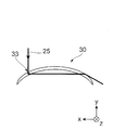
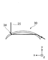
- 6A, 6B, and 6C are diagrams for explaining the contact member 30 with a reflecting portion and the optical path 25 to which the second embodiment is applied.
- 6A is a front view of the contact member 30 with a reflecting portion
- FIG. 6B is an example of a setting method of the optical path 25
- FIG. 6C is an example of another setting method of the optical path 25.
- the eyeball 10 is the right eye, but in the case of the left eye, the left and right may be reversed.
- the reflective member with a reflective part 30 is provided with one reflective part 33 or a reflective part 34.
- the optical path 25 is set to be incident on the reflecting portion 33 of the contact member 30 with the reflecting portion.
- the light reflected by the reflection portion 33 passes through the aqueous humor of the anterior chamber 13 from the contact member 30 with the reflection portion and again enters the contact member 30 with the reflection portion. Then, the light is refracted at the interface between the contact member 30 with a reflecting portion and the air and emitted.
- the light emitting system 21 (see FIG. 1A) is provided in front of the eyeball 10, and the light receiving system 22 (see FIG. 1A) is provided on the ear side.
- the optical path 25 is set in a direction in which light is emitted from the reflection portion 34 of the contact member 30 with a reflection portion. That is, light is incident on the contact member 30 with the reflection portion from the ear side, passes through the aqueous humor of the anterior chamber 13, is reflected by the reflection portion 34 of the contact member 30 with the reflection portion, and is emitted. That is, the light emitting system 21 (see FIG. 1A) is provided on the ear side, and the light receiving system 22 (see FIG. 1A) is provided in front of the eyeball 10.
- a sealing member 33c may be provided in the cutout portion 33a of the reflection portion 33, and a sealing member 34c may be provided in the cutout portion 34a of the reflection portion 34.
- the contact member 30 with a reflecting portion to which the first embodiment is applied has a reflecting portion 33 having one mirror 33b on the incident side and a reflecting portion 34 having one mirror 34b on the emitting side. .
- a contact member 30 with a reflecting portion is attached to the eyeball 10
- the optical path 25 as shown in FIG. 1A may be difficult to set.
- the contact member 30 with a reflecting portion to which the third embodiment is applied the contact member 30 with a reflecting portion is allowed to rotate around the center of the eyeball 10 and the optical path 25 is easily set.
- the third embodiment is the same as the first embodiment except that the configuration of the contact member 30 with the reflecting portion is different. Below, the description of the same part is abbreviate
- FIGS. 7A and 7B are front views of the contact member 30 with a reflecting portion to which the third embodiment is applied.
- FIG. 7A is an example of the contact member 30 with a reflective portion
- FIG. 7B is another example of the contact member 30 with a reflective portion.
- the left side will be described as the incident side where light enters from the light emitting system 21 (see FIG. 1A)
- the right side will be described as the emitting side from which light is emitted to the light receiving system 22 (see FIG. 1A).
- the outer shape of the contact member 30 with a reflecting portion is circular.
- a plurality of reflecting portions 331 and 332 are provided in a circular arc shape having the center of the circular contact member 30 with a reflecting portion as a concentric axis.
- a plurality of arc-shaped reflecting portions 341 to 343 having the center of the circular contact member 30 with a reflecting portion as a concentric axis are provided on the emission side. That is, the incident-side reflection unit 33 includes reflection units 331 and 332, and the output-side reflection unit 34 includes reflection units 341 to 343. That is, it can be said that the reflection part 33 on the incident side and the reflection part 34 on the emission side include the reflection parts in groups.
- the reflection part 33 on the incident side and the reflection part 34 on the emission side provided with the reflection part as a group are read as the reflection part group 33 and the reflection part group 34, respectively.
- the reflection unit group 33 is an example of a first reflection unit
- the reflection unit group 34 is an example of a second reflection unit.
- the light incident point IN is indicated on the reflecting part 331 constituting the incident side reflecting part group 33
- the light emitting point OUT is indicated on the reflecting part 342 constituting the reflecting side group 34 on the emitting side.
- the size relationship between the diameter of the light on the contact member 30 with a reflecting portion and the reflecting portion is one reflecting portion (reflecting portion).
- the light diameter may be included in the part 331 and the reflection part 342), or the light diameter may be larger than the width of one reflection part, for example, a size over a plurality of reflection parts. Also good.
- the configurations of the reflecting portions 331 and 332 and the reflecting portions 341 to 343 may be any of those shown in FIGS. 3A, 3B, and 3C.
- the shapes of the reflecting portions 331, 332, and 341 to 343 are arcuate so that the contact member 30 with a reflecting portion is centered on the center of the eyeball. Rotation is allowed.
- the incident-side reflecting portion group 33 includes a plurality of reflecting portions 331 and 332 separated in the diameter direction of the contact member 30 with a reflecting portion. That is, the area of the reflective surface is enlarged along the curved surface shape in the diameter direction of the contact member 30 with a reflective portion.
- the exit-side reflecting portion group 34 is composed of a plurality of reflecting portions 341 to 343 separated in the diameter direction of the contact member 30 with a reflecting portion. Therefore, even when the shape of the cornea 14 changes due to individual differences or daily fluctuations of the person being measured, and the angle of the reflected light (optical path 25) deviates from the desired direction, it is directed toward the light receiving system 22. It is easy to reflect light. For example, even if the emission point OUT of the contact member 30 with the reflection part moves from the reflection part 342 to the reflection part 341 or the reflection part 343, the light is reflected toward the light receiving system 22.
- two reflecting portions 331 and 332 are provided in the reflecting portion group 33 on the incident side, and three reflecting portions 341 to 343 are provided in the reflecting portion group 34 on the exit side. That is, the exit side has a larger number of reflection parts than the incident side, and has a reflection surface with a large area. This is because, on the emission side, it is necessary to consider the variation in the optical path 25 more than that on the incident side because the angle of the reflected light (optical path 25) may be shifted due to the influence of the shape of the cornea 14 and the like. Because there is.
- the number of reflecting portions provided in the reflecting portion group 33 on the incident side and the reflecting portion group 34 on the exit side is not limited to the above number.
- Other configurations are the same as those in FIG. It is not necessary to divide into three. Even if each of the reflecting portions 331 and 332 and the reflecting portions 341 to 343 is divided into three parts, the reflecting portions 331 and 332 and the reflecting portions 341 to 343 are arranged in an arc shape, so that rotation around the center of the eyeball 10 of the contact member 30 with a reflecting portion is allowed.
- the angle of the light reflected by the influence of the shape of the cornea 14 (the optical path 25). ) May be set so as to deviate, the light incident from the light emitting system 21 can be emitted to the light receiving system 22.
- the shape of the reflection parts 33 and 34 of the contact member 30 with a reflection part to which the first embodiment and the second embodiment are applied is the same as the contact member with a reflection part to which the third embodiment is applied.
- it may be arcuate.
- the contact member 30 with a reflective portion to which the third embodiment is applied includes the reflective portions 331 and 332 in the reflective portion group 33 on the incident side, and the reflective portions in the reflective portion group 34 on the outgoing side. 341 to 343 were arranged with a gap between the reflecting portions.
- a plurality of reflecting portions in the reflecting portion group 33 on the incident side and a plurality of reflecting portions in the reflecting portion group 34 on the exit side are gaps when viewed from the y direction. There is no array.
- the fourth embodiment is the same as the third embodiment except that the configuration of the contact member 30 with a reflecting portion is different. Below, the description of the same part is abbreviate
- FIG. 8A and 8B are views for explaining the contact member 30 with a reflecting portion to which the fourth embodiment is applied.
- 8A is a front view of the contact member 30 with a reflecting portion and a view showing the relationship with the eyeball 10
- FIG. 8B is an enlarged view of the reflecting portion group 33 on the incident side.
- the left side will be described as the incident side where light enters from the light emitting system 21 (see FIG. 1A), and the right side will be described as the outgoing side from which light is emitted to the light receiving system 22 (see FIG. 1A).
- the contact member 30 with the reflection portion to which the fourth embodiment is applied includes a reflection portion group 33 having reflection portions 331 and 332 on the incident side, and reflection on the emission side.
- a reflecting portion group 34 having portions 341 to 345 is provided.
- the reflecting portions 331 and 332 and the reflecting portions 341 to 345 are concentric arcs with the center of the contact member 30 with a reflecting portion having a circular outer shape as an axis.
- the reflecting portions 331 and 332 in the incident-side reflecting portion group 33 and the reflecting portions 341 to 345 in the emitting-side reflecting portion group 34 are arranged so that there is no gap when viewed from the + y-axis direction.
- the incident point IN is provided in the reflection part 332 in the reflection part group 33 on the incident side
- the emission point OUT is provided across the reflection part 342 and the reflection part 343 in the reflection part group 34 on the emission side.
- the configurations of the reflecting portions 331 and 332 and the reflecting portions 341 to 345 may be any of those shown in FIGS. 3A, 3B, and 3C.
- the light diameter is larger than the size of each of the reflecting portions 331 and 332 and the reflecting portions 341 to 345, the light can be reflected by a plurality of reflecting portions. Therefore, the light can be reflected more efficiently without losing light than in the case of a single reflecting portion. That is, the area of an effective reflecting surface (mirror) is enlarged by constituting with a plurality of reflecting portions.
- the laser light when viewed from the + y-axis direction, even if laser light having high coherency is used for the light emitting part 211, the laser light can be obtained by arranging the reflecting parts 331 and 332 of the reflecting part group 33 on the incident side without gaps. Is prevented from entering the inside of the eyeball 10 and irradiating the retina 16.
- the reflecting portions 341 to 345 of the reflecting portion group 34 when viewed from the + y-axis direction, by arranging the reflecting portions 341 to 345 of the reflecting portion group 34 on the emission side without any gap, for example, light that has passed through the anterior chamber 13 straddles a plurality of reflecting portions. Even when the light is reflected, the reflected light is emitted toward the light receiving system 22 without expanding its diameter.
- the contact member 30 with a reflective portion to which the third embodiment is applied in the contact member 30 with a reflective portion to which the fourth embodiment is applied, the reflection portions 331, 332, 341 to 345
- the contact member 30 with a reflecting portion is allowed to rotate around the center of the eyeball.
- the contact member 30 with a reflecting portion is allowed to rotate around the center of the eyeball.
- the incident-side reflecting portion group 33 when the plurality of reflecting portions are arranged without a gap when viewed from the + y direction, even if a part of the light reflected by one reflecting portion is partly reflected by other reflecting portions. It is good not to be shielded (not cut). If even a part of the light is shielded (cut) by another reflecting portion, the amount of light is reduced, and measurement may be impossible or accuracy may be reduced.
- the right end of the mirror 332b is set so as not to block (cut off) the reflected light ⁇ ′.
- the reflected light ⁇ ′ for the incident light ⁇ incident on the right end of the mirror 332b is set to be reflected in the same direction as the reflected light ⁇ ′.
- the angle formed by the mirror 331b with the y-axis and the angle formed by the mirror 332b with the y-axis may be the same or different.
- the sealing member 33c is provided so as to smooth the surface of the contact member 30 with the reflecting portion, it is affected by the curved surface shape, so that the mirrors 331b and 332b
- the angles with respect to the respective y axes may be different.
- the mirrors of the reflecting portions 341 to 345 are also reflected by the same considerations. It is set not to be shielded (cut) by the part.
- FIG. 9 is a diagram for explaining a method of setting the reflecting mirror (reflecting surface) in the reflecting portion group 33 on the incident side and the reflecting mirror (reflecting surface) in the reflecting portion group 34 on the exit side.
- a part of the conical surface cut by two surfaces parallel to the bottom surface of the cone is used to form the reflecting portion 331 in the reflecting portion group 33 on the incident side.
- a mirror 331b (reflecting surface) and a mirror 342b (reflecting surface) of the reflecting portion 342 in the reflecting portion group 34 on the emission side are configured.
- the mirror 331b and the mirror 342b are fan-shaped with sides of arcs having the same distance from the y-axis. Note that the mirror 331b and the mirror 342b do not have to have the same arc as the side from the y-axis.
- the respective mirrors 332b, 341b, 343b to 345b of the other reflecting portions 332, 341, 343 to 345 may be formed of similar cones or cones having different cone apex angles. Assuming cones having different cone apex angles, the mirrors 331b and 332b and the mirrors 341b to 345b are configured, whereby the angles with respect to the y-axis can be made different. By forming mirrors with different angles with respect to the y-axis in this way, even if the corneal shape fluctuates and the reflection angle at the mirror deviates from the design value, light is incident on the mirrors at other angles. It is easy to secure an optical path that can cross the eye chamber 13 and can be received by the light receiving system 22.
- the optical measurement device 20 is operated so that the light is incident on the mirror 332b having a different angle. By doing so, the possibility of light reaching the light receiving system 22 through a desired optical path is increased.
- a setting method for forming mirrors having different angles with respect to the y-axis not only a configuration assuming a cone, but also an elliptical cone having a vertex in the ⁇ y direction, two parallel to the bottom surface of the elliptical cone are assumed. You may comprise by a part of elliptical cone surface cut off by a surface.
- the angle with respect to the y-axis varies depending on the position in the circumferential direction on the elliptical cone surface, so that a mirror whose angle gradually changes can be formed as a continuous surface. In this way, light can be reflected at different angles by one mirror without providing a plurality of mirrors.
- This configuration is applicable not only to the configuration of the reflection units 331, 332, and 341 to 345 in the reflection unit groups 33 and 34 shown in FIG. 9, but also to the configuration shown in FIGS. 7A and 7B.
- the contact member 30 with a reflecting portion to which the fourth embodiment is applied includes a plurality of reflecting portions constituting the reflecting portion group 33 on the incident side and a plurality of reflecting portions constituting the reflecting portion group 34 on the exit side. I was prepared.
- the reflecting portion constituting the reflecting portion group 33 and the reflecting portion constituting the reflecting portion group 34 on the emission side are not separated.
- the fifth embodiment is the same as the third embodiment except that the configuration of the contact member 30 with the reflecting portion is different. Below, the description of the same part is abbreviate
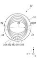
- 10A, 10B, and 10C are front views of the contact member 30 with a reflecting portion to which the fifth embodiment is applied.
- 10A shows an example in which the reflecting portions 351 to 354 are provided in a circular shape
- FIG. 10B shows an example in which the reflecting portions 351 to 355 are provided in an elliptical shape
- FIG. 10C shows that the reflecting portions 351 to 354 are provided in an elliptical shape. Is another example.
- the left side is described as the incident side on which light is incident from the light emitting system 21 (see FIG. 1A)
- the right side is described as the emitting side from which light is emitted to the light receiving system 22 (see FIG. 1A).
- the reflective portions 351 to 354 are provided in a concentric circular shape with the center of the contact member 30 with a reflective portion having a circular outer shape as an axis.
- the left portion functions as the reflecting portion group 33 on the incident side
- the right portion functions as the reflecting portion group 34 on the exit side. That is, the reflecting portions 351 to 354 are continuous.
- the incident point IN is on the left side of the reflecting portion 352
- the emission point OUT is on the right side of the reflecting portion 352.
- the reflective portions 351 to 355 have an elliptical shape provided in the circular contact member 30 with a reflective portion.
- the reflective portions 351 to 355 are provided with a gap in the ⁇ z direction.
- the left portion functions as the reflecting portion group 33 on the incident side
- the right portion functions as the reflecting portion group 34 on the exit side.
- the incident point IN is on the left side of the reflecting portion 351
- the exit point OUT is on the right side of the reflecting portion 351.
- the contact member 30 with a reflective portion shown in FIG. 10B can change the distance between the incident point IN and the outgoing point OUT depending on the mounting direction. Therefore, it is made to respond
- the reflecting portions 351 to 355 have an elliptical shape provided in the circular contact member 30 with a reflecting portion. Note that the reflecting portions 351 to 354 are arranged with no gap therebetween. In the reflecting portions 351 to 354, the left portion is the reflecting portion group 33 on the incident side, and the right portion is the reflecting portion group 34 on the exit side. In FIG. 10C, as an example, the reflecting portion 351 has an incident point IN and the reflecting portion 351 has an exit point OUT. 10C can change the distance between the incident point IN and the outgoing point OUT depending on the mounting direction.
- the configuration of the reflective portion (such as the reflective portions 351 to 354 in FIG. 10A) of the contact member 30 with the reflective portion is any of the configurations described in FIGS. 3A, 10B, and 10C. Other configurations may also be used.
- 10A, 10B, and 10C can be set by a method similar to the setting method described with reference to FIG. 9.
- the mirrors of the reflecting portions (reflecting portions 351 to 354 in FIG. 10A) can be set.
- the reflection part 33 on the incident side and the reflection part 34 on the emission side of the contact member 30 with the reflection part to which the first embodiment is applied may be connected in a circular shape or an elliptical shape.
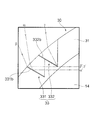
- FIG. 11 is a front view of a contact member 30 with a reflecting portion to which the sixth embodiment is applied.
- the left side is described as the incident side where light enters from the light emitting system 21 (see FIG. 1A), and the right side is described as the emitting side where light is emitted to the light receiving system 22 (see FIG. 1A).
- the contact member 30 with a reflection portion to which the sixth embodiment is applied includes a base 31, an incident-side reflection portion 33, and an emission-side reflection portion 34.
- the base 31 includes a thin region I on the upper side in the z direction and a thick region II on the lower side in the z direction.
- the thick region II becomes a “weight”
- the contact member 30 with the reflecting portion rotates along the rotation direction with the center as an axis, and assumes a predetermined orientation. Therefore, it becomes the same direction every time it is mounted and it is easy to mount.
- Such a contact member 30 with a reflecting portion can be manufactured by changing the shape of the die 50 in the spin casting method, the female die 61 in the molding method, and the male die 65.
- a light shielding region in which a light shielding film is formed is provided on the surface of the contact member 30 with a reflective portion to which the first embodiment is applied.
- the seventh embodiment is the same as the first embodiment except that the configuration of the contact member 30 with a reflecting portion is different. Below, the description of the same part is abbreviate
- FIG. 12 is a diagram for explaining a contact member 30 with a reflecting portion to which the seventh embodiment is applied.
- the front view of the contact member 30 with a reflection part and the relationship with the eyeball 10 are shown.
- the left side will be described as the incident side where light enters from the light emitting system 21 (see FIG. 1A), and the right side will be described as the emitting side where light exits from the light receiving system 22 (see FIG. 1A).
- the contact member 30 with a reflection portion to which the seventh embodiment is applied includes a base 31, an incident-side reflection portion 33, and an emission-side reflection portion 34, as in the first embodiment.
- the laser beam is formed by the incident-side reflecting unit 33. It is made not to irradiate off the predetermined area
- the light shielding film 36 shields the laser light by reflecting or absorbing the laser light, and is made of, for example, a metal film or a black film.
- the light shielding film 36 may be provided so as to cover at least a part of the pupil, and may be provided so as to cover the entire pupil when it is not necessary to secure the visual field of the measurement subject.
- Such a light shielding film 36 is formed by the above-described printing method, roll coating method, spray coating method or the like.
- the light shielding film 36 is provided on at least one of the inner ( ⁇ y direction side) and outer (+ y direction side) surfaces of the base 31 of the contact member 30 with a reflecting portion.
- the portion 31 may be made of a light shielding material (resin or the like). Further, it is not necessary to completely shield the laser beam, and it is sufficient that the laser beam is shielded as compared with the case where the substrate 31 is made of a colorless and transparent material.
- the optical measurement system 1 of the eyeball has been described as measuring the concentration of the optically active substance desired to be obtained contained in the aqueous humor, but may be configured to measure other characteristics of the aqueous humor. Good. Further, in order to obtain not only the characteristics relating to aqueous humor but also the characteristics relating to the cornea and the like existing in the optical path 25, the configurations described in the first to seventh embodiments may be applied.
- the configuration of the contact member 30 with a reflecting portion described as the first to seventh embodiments may be combined with each other or modified as long as there is no technical contradiction. Further, the present disclosure is not limited to the first to seventh embodiments, and can be implemented in various forms without departing from the gist of the present disclosure.
- SYMBOLS 1 Optical measurement system of eyeball, 10 ... Eyeball, 13 ... Anterior chamber, 14 ... Cornea, 16 ... Retina, 20 ... Optical measuring device, 21 ... Light emission system, 22 ... Light reception system, 23 ... Control part, 24 ... Calculation , 25 ... optical path, 30 ... contact member with reflecting part, 31 ... base, 33, 34 ... reflecting part (reflecting part group), 33a, 34a ... notch part, 33b, 34b, 331b-332b, 341b-345b ... Mirror, 33c, 34c ... sealing member, 36 ... light shielding film, 50, 50 '... mold, 51, 62 ...
Landscapes
- Life Sciences & Earth Sciences (AREA)
- Health & Medical Sciences (AREA)
- Medical Informatics (AREA)
- Biophysics (AREA)
- Ophthalmology & Optometry (AREA)
- Engineering & Computer Science (AREA)
- Biomedical Technology (AREA)
- Heart & Thoracic Surgery (AREA)
- Physics & Mathematics (AREA)
- Molecular Biology (AREA)
- Surgery (AREA)
- Animal Behavior & Ethology (AREA)
- General Health & Medical Sciences (AREA)
- Public Health (AREA)
- Veterinary Medicine (AREA)
- Eye Examination Apparatus (AREA)
Abstract
眼球の光計測システムは、眼球の前方から入射した光を前眼房を横切るように反射する反射部と、前眼房を横切った光を眼球の前方に反射する反射部との少なくとも一方を有し、眼球面に装着される反射部付きコンタクト部材と、前眼房に向けて光を出射する発光系と、前眼房を横切った光を受光する受光系とを有し、反射部付きコンタクト部材と分離された状態で眼球の前方に配置される光計測装置と、を備える。
Description
本発明は、眼球の光計測システム及び眼球用の装着部材に関する。
特許文献1には、眼球を利用したグルコース濃度を測定する装置において、角膜の頂部よりも奥側に光出射手段及び受光手段を配置して、前眼房を横切るように光を出射及び受光する構成の光計測装置が開示されている。
角膜の頂部よりも奥側に光出射手段及び受光手段を配置して前眼房を横切るように光を出射及び受光する構成の光計測装置では、眼球周辺の皮膚等が障害となり、光出射手段及び受光手段を配置する空間を確保しづらかった。
本発明の少なくとも一の実施形態は、角膜の頂部よりも奥側に光出射部及び受光部を配置する構成と比較し、光出射部又は受光部を配置する空間の確保が容易な、眼球の光計測システム及び眼球用の装着部材を提供することを目的とする。
本発明の少なくとも一の実施形態は、角膜の頂部よりも奥側に光出射部及び受光部を配置する構成と比較し、光出射部又は受光部を配置する空間の確保が容易な、眼球の光計測システム及び眼球用の装着部材を提供することを目的とする。
[1]本発明の少なくとも一の実施形態は、眼球の前方から入射した光を前眼房を横切るように反射する第1の反射部と、当該前眼房を横切った前記光を眼球の前方に反射する第2の反射部との少なくとも一方を有し、眼球面に装着される装着部材と、前記前眼房に向けて光を出射する光出射部と、当該前眼房を横切った光を受光する受光部とを有し、前記装着部材と分離された状態で眼球の前方に配置される光計測装置と、を備える眼球の光計測システムである。
[2]上記[1]の眼球の光計測システムにおいて、前記装着部材は眼球の角膜に沿った形状を有し、角膜上に装着されてもよい。
[3]上記[1]または[2]の眼球の光計測システムにおいて、前記装着部材が有する前記第1の反射部と前記第2の反射部との少なくとも一方は金属面で構成されていてもよい。
[4]上記[1]~[3]のいずれかの眼球の光計測システムにおいて、前記装着部材は前記第1の反射部を有し、前記第1の反射部は、当該第1の反射部に入射する光のビーム径を包含する大きさに形成されてもよい。
[5]上記[1]~[4]のいずれかの眼球の光計測システムにおいて、前記装着部材が有する前記第1の反射部と前記第2の反射部との少なくとも一方は、複数の反射面で構成されていてもよい。
[6]上記[1]~[5]のいずれかの眼球の光計測システムにおいて、前記装着部材は前記第1の反射部及び前記第2の反射部を有していてもよく、前記第2の反射部は前記第1の反射部よりも面積が大きくてもよい。
[7]上記[6]の眼球の光計測システムにおいて、前記装着部材が有する前記第1の反射部及び前記第2の反射部の少なくとも一方は、当該装着部材の中心を軸とした円弧状の形状を有していてもよい。
[8]上記[1]~[5]のいずれかの眼球の光計測システムにおいて、前記装着部材は前記第1の反射部及び前記第2の反射部を有していてもよく、前記装着部材に設けられた円形状の連続した反射面が、前記第1の反射部及び前記第2の反射部として機能してもよい。
[9]上記[1]~[8]のいずれかの眼球の光計測システムにおいて、前記装着部材は、眼球に装着した場合に、当該装着部材の中心を軸とした回転方向における予め定めた向きに配置される形状であってもよい。
[10]上記[1]~[9]のいずれかの眼球の光計測システムにおいて、前記装着部材は、前記光出射部から出射された光が入射する当該装着部材上の予め定められた入射領域以外の領域に、当該光が眼球に達することを遮る遮光領域を有していてもよい。
[11]本発明の少なくとも一の実施形態は、眼球の前方から入射した光を前眼房を横切るように反射する第1の反射部と、当該前眼房を横切った光を眼球の前方に反射する第2の反射部との少なくとも一方を備え、前記前眼房に向けて光を出射する光出射部及び当該前眼房を横切った光を受光する受光部とともに用いられ、当該光出射部及び当該受光部とは分離された状態で眼球面に装着される眼球用の装着部材である。
[2]上記[1]の眼球の光計測システムにおいて、前記装着部材は眼球の角膜に沿った形状を有し、角膜上に装着されてもよい。
[3]上記[1]または[2]の眼球の光計測システムにおいて、前記装着部材が有する前記第1の反射部と前記第2の反射部との少なくとも一方は金属面で構成されていてもよい。
[4]上記[1]~[3]のいずれかの眼球の光計測システムにおいて、前記装着部材は前記第1の反射部を有し、前記第1の反射部は、当該第1の反射部に入射する光のビーム径を包含する大きさに形成されてもよい。
[5]上記[1]~[4]のいずれかの眼球の光計測システムにおいて、前記装着部材が有する前記第1の反射部と前記第2の反射部との少なくとも一方は、複数の反射面で構成されていてもよい。
[6]上記[1]~[5]のいずれかの眼球の光計測システムにおいて、前記装着部材は前記第1の反射部及び前記第2の反射部を有していてもよく、前記第2の反射部は前記第1の反射部よりも面積が大きくてもよい。
[7]上記[6]の眼球の光計測システムにおいて、前記装着部材が有する前記第1の反射部及び前記第2の反射部の少なくとも一方は、当該装着部材の中心を軸とした円弧状の形状を有していてもよい。
[8]上記[1]~[5]のいずれかの眼球の光計測システムにおいて、前記装着部材は前記第1の反射部及び前記第2の反射部を有していてもよく、前記装着部材に設けられた円形状の連続した反射面が、前記第1の反射部及び前記第2の反射部として機能してもよい。
[9]上記[1]~[8]のいずれかの眼球の光計測システムにおいて、前記装着部材は、眼球に装着した場合に、当該装着部材の中心を軸とした回転方向における予め定めた向きに配置される形状であってもよい。
[10]上記[1]~[9]のいずれかの眼球の光計測システムにおいて、前記装着部材は、前記光出射部から出射された光が入射する当該装着部材上の予め定められた入射領域以外の領域に、当該光が眼球に達することを遮る遮光領域を有していてもよい。
[11]本発明の少なくとも一の実施形態は、眼球の前方から入射した光を前眼房を横切るように反射する第1の反射部と、当該前眼房を横切った光を眼球の前方に反射する第2の反射部との少なくとも一方を備え、前記前眼房に向けて光を出射する光出射部及び当該前眼房を横切った光を受光する受光部とともに用いられ、当該光出射部及び当該受光部とは分離された状態で眼球面に装着される眼球用の装着部材である。
[1]に記載の眼球の光計測システムによれば、角膜の頂部よりも奥側に光出射部及び受光部を配置する構成と比較し、光出射手段又は受光手段を配置する空間の確保が容易になる。
[2]に記載の眼球の光計測システムによれば、角膜に沿っていない形状と比較し、角膜上に装着しやすい。
[3]に記載の眼球の光計測システムによれば、樹脂材料による反射面と比較し、反射率を高めやすい。
[4]に記載の眼球の光計測システムによれば、反射部がビーム径より小さい場合と比較し、多くの光を前眼房に向けて反射できる。
[5]に記載の眼球の光計測システムによれば、単一の反射面で構成する場合と比較し、装着部材の形状に沿って反射面の面積を大きくしやすい。
[6]に記載の眼球の光計測システムによれば、第1の反射部で反射される光の角度が変動した場合であっても、第2の反射部に光を入射しやすくなる。
[7]に記載の眼球の光計測システムによれば、円弧状ではない構成と比較し、装着部材が眼球上で回転した場合であっても、光の入射位置が反射部からずれるのが抑制される。
[8]に記載の眼球の光計測システムによれば、第1の反射部及び第2の反射部が分離して設けられている構成と比較し、装着部材が眼球上で回転した場合であっても、光の入射位置が反射部からずれるのが抑制される。
[9]に記載の眼球の光計測システムによれば、眼球上で装着部材をあらかじめ定めた向きに維持しやすい。
[10]に記載の眼球の光計測システムによれば、光出射部から出射された光が装着部材上の予め定められた入射領域から外れた場合に、意図しない眼球の領域が照射されることが抑制される。
[11]に記載の眼球の装着部材によれば、角膜の頂部よりも奥側に光出射部及び受光部を配置する構成と比較し、光出射部又は受光部を配置する空間の確保が容易になる。
[2]に記載の眼球の光計測システムによれば、角膜に沿っていない形状と比較し、角膜上に装着しやすい。
[3]に記載の眼球の光計測システムによれば、樹脂材料による反射面と比較し、反射率を高めやすい。
[4]に記載の眼球の光計測システムによれば、反射部がビーム径より小さい場合と比較し、多くの光を前眼房に向けて反射できる。
[5]に記載の眼球の光計測システムによれば、単一の反射面で構成する場合と比較し、装着部材の形状に沿って反射面の面積を大きくしやすい。
[6]に記載の眼球の光計測システムによれば、第1の反射部で反射される光の角度が変動した場合であっても、第2の反射部に光を入射しやすくなる。
[7]に記載の眼球の光計測システムによれば、円弧状ではない構成と比較し、装着部材が眼球上で回転した場合であっても、光の入射位置が反射部からずれるのが抑制される。
[8]に記載の眼球の光計測システムによれば、第1の反射部及び第2の反射部が分離して設けられている構成と比較し、装着部材が眼球上で回転した場合であっても、光の入射位置が反射部からずれるのが抑制される。
[9]に記載の眼球の光計測システムによれば、眼球上で装着部材をあらかじめ定めた向きに維持しやすい。
[10]に記載の眼球の光計測システムによれば、光出射部から出射された光が装着部材上の予め定められた入射領域から外れた場合に、意図しない眼球の領域が照射されることが抑制される。
[11]に記載の眼球の装着部材によれば、角膜の頂部よりも奥側に光出射部及び受光部を配置する構成と比較し、光出射部又は受光部を配置する空間の確保が容易になる。
以下、添付図面を参照して、本発明の実施の形態について説明する。
[第1の実施の形態]
(眼球の光計測システム1)
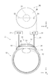
図1A、1Bは、第1の実施の形態が適用される眼球の光計測システム1の構成の一例を示す図である。図1Aは、眼球10及び眼球の光計測システム1、図1Bは、眼球10に装着される反射部付きコンタクト部材30の正面図である。なお、正面図とは、図1Bに示す+y方向から見た場合の反射部付きコンタクト部材30の図である。図1Aは、図1BのIA-IA線での断面図である。
眼球の光計測システム1は、眼球10に向けて光を出射する発光系21と、眼球10からの光を受光する受光系22とを備える光計測装置20と、眼球10の角膜上(眼球面)に装着される装着部材(眼球用の装着部材)の一例としての反射部付きコンタクト部材30とを備える。光計測装置20における発光系21が光出射部の一例であり、受光系22が受光部の一例である。
(眼球の光計測システム1)
図1A、1Bは、第1の実施の形態が適用される眼球の光計測システム1の構成の一例を示す図である。図1Aは、眼球10及び眼球の光計測システム1、図1Bは、眼球10に装着される反射部付きコンタクト部材30の正面図である。なお、正面図とは、図1Bに示す+y方向から見た場合の反射部付きコンタクト部材30の図である。図1Aは、図1BのIA-IA線での断面図である。
眼球の光計測システム1は、眼球10に向けて光を出射する発光系21と、眼球10からの光を受光する受光系22とを備える光計測装置20と、眼球10の角膜上(眼球面)に装着される装着部材(眼球用の装着部材)の一例としての反射部付きコンタクト部材30とを備える。光計測装置20における発光系21が光出射部の一例であり、受光系22が受光部の一例である。
図1Aに示すように、人の眼球10は、外形がほぼ球形であって、中央にガラス体11を有する。レンズの役割をする水晶体12が、ガラス体11の一部に埋め込まれている。水晶体12の外側に、前眼房13があり、その外側に角膜14がある。水晶体12の周辺部は虹彩に囲まれ、その中心が瞳孔15である。水晶体12に接する部分を除いて、ガラス体11は、網膜16で覆われている。そして、前眼房13は、眼房水で満たされている。
ここで、図1Aにおいて、+x方向が顔(眼球10)の右方向、-x方向が顔(眼球10)の左方向、+y方向が顔(眼球10)の前方向(前方、手前側)、-y方向が顔(眼球10)の後方向(後方、奥側)、+z方向が顔(眼球10)の上方向、-z方向が顔(眼球10)の下方向とする。図1Aの眼球10部分は、眼球10を下方向から見た図である。
ここで、図1Aにおいて、+x方向が顔(眼球10)の右方向、-x方向が顔(眼球10)の左方向、+y方向が顔(眼球10)の前方向(前方、手前側)、-y方向が顔(眼球10)の後方向(後方、奥側)、+z方向が顔(眼球10)の上方向、-z方向が顔(眼球10)の下方向とする。図1Aの眼球10部分は、眼球10を下方向から見た図である。
図1Aに示すように、光計測装置20は、発光系21、受光系22に加えて、制御部23と、算出部24とを備える。発光系21は、光を出射する発光部211と、入射した光から予め定められた直線偏光を取り出す偏光子212とを備える。受光系22は、前眼房13における眼房水で振動方向が回転した直線偏光の回転角を補償する補償子221と、予め定められた偏光角の光を通過させる検光子222と、受光した光の強度を電気信号に変換する受光部223とを備える。
光計測装置20について、後に詳述する。
光計測装置20について、後に詳述する。
図1Aに示すように、反射部付きコンタクト部材30は、いわゆるコンタクトレンズと同様の眼球用の部材であって、眼球10における角膜14の表面(眼球面)に装着される。なお、眼球10における角膜14の表面(眼球面)に反射部付きコンタクト部材30が装着されることを、以下では、眼球10に反射部付きコンタクト部材30が装着されると表現する。
反射部付きコンタクト部材30は、基体31と、二つの反射部33、34とを備える。二つの反射部33、34は、反射部付きコンタクト部材30が眼球10の表面に装着された際に、前眼房13を挟む位置に設けられている。ここでは、反射部33、34は、x方向に並んで設けられている。
反射部付きコンタクト部材30は、基体31と、二つの反射部33、34とを備える。二つの反射部33、34は、反射部付きコンタクト部材30が眼球10の表面に装着された際に、前眼房13を挟む位置に設けられている。ここでは、反射部33、34は、x方向に並んで設けられている。
反射部33は、光計測装置20の発光系21が出射した光を、前眼房13の眼房水を横切るように反射する。一方、反射部34は、前眼房13の眼房水を横切った光を光計測装置20の受光系22に入射するように反射する。ここで、反射部33が、第1の反射部の一例であり、反射部34が、第2の反射部の一例である。反射部33、34は、例えば、平面ミラーで構成される。
なお、図1Bに示すように、反射部33、34は、反射部付きコンタクト部材30の直径となる線上に配置されているが、直径となる線に平行な線上に配置されていてもよい。例えば、眼瞼下垂患者や高齢者のように、瞼が垂れ下がって上瞼が開けづらい被計測者に対しては、直径となる線上より下瞼に近い側にずれた線上に、反射部33、34が配置されている方がよい。このようにすれば、上瞼が開けづらい場合であっても、前眼房13の眼房水を横切る光路25が確保しやすくなる。
また、反射部付きコンタクト部材30の反射部33、34は、眼球10に対して上下方向(z方向)に前眼房13を挟むように設けられてもよい。さらに、眼球10に対して斜め方向(左斜め上方から右斜め下方、又は、右斜め上方から左斜め下方)に前眼房13を挟むように設けられてもよい。反射部付きコンタクト部材30の反射部33、34が眼球10の左右方向又は斜め方向に設けられると、睫毛の影響を受けにくい。なお、第1の実施の形態(他の実施の形態を含む)において、眼房水を「横切る」とは、眼球10の上下方向、左右方向及び斜め方向に眼房水を通過するいずれの経路も含み、眼球10の手前側から奥側に眼房水を通過する経路は含まない。
反射部付きコンタクト部材30については、後に詳述する。
反射部付きコンタクト部材30については、後に詳述する。
なお、眼球10に反射部付きコンタクト部材30を装着しない場合、眼球10の左右方向(+x方向及び-x方向)、すなわち、角膜14の頂部(y方向の先端部)よりも後方(奥側)に発光系21及び受光系22を配置することになる。しかし、このような場合は、鼻などの眼球10周辺の皮膚が邪魔をして、発光系21又は受光系22を配置する空間が確保しづらい。また、仮に空間を確保して発光系21又は受光系22を配置できたとしても、発光系21又は受光系22が眼球10に接触しやすい配置となる。
第1の実施の形態では、反射部付きコンタクト部材30を眼球10に装着することで、発光系21及び受光系22が眼球10の前方(手前側)に設けられる。すなわち、発光系21及び受光系22を設ける空間が確保しやすい。また、発光系21又は受光系22を眼球10から離すことで、発光系21又は受光系22が眼球10に接触する可能性が低減される。
第1の実施の形態では、反射部付きコンタクト部材30を眼球10に装着することで、発光系21及び受光系22が眼球10の前方(手前側)に設けられる。すなわち、発光系21及び受光系22を設ける空間が確保しやすい。また、発光系21又は受光系22を眼球10から離すことで、発光系21又は受光系22が眼球10に接触する可能性が低減される。
光計測装置20は、反射部付きコンタクト部材30とは物理的に分離されており、計測時において、反射部付きコンタクト部材30が装着された眼球10の前方に位置決めされる。光計測装置20は、例えば、ヘッドマウントタイプ、眼鏡タイプなどに構成しうる。発光系21及び受光系22は、光計測装置20と反射部付きコンタクト部材30との間の光路25が、図1Bに示すように、x方向に沿った光路となる位置に設けられる。例えば、y方向から見た場合に、発光系21及び受光系22が反射部付きコンタクト部材30の反射部33及び反射部34と重なる位置に設けられる。ただし、必ずしもx方向に沿った光路である必要はなく、x方向に対して斜めの光路となる位置に発光系21及び受光系22が設けられてもよい。
なお、光計測装置20は、発光系21と受光系22とが逆に構成されていてもよい。
なお、光計測装置20は、発光系21と受光系22とが逆に構成されていてもよい。
(眼球の光計測システム1を用いたグルコース濃度の算出方法)
ここで、前眼房13における眼房水を計測し、グルコース濃度の算出に眼球の光計測システム1を用いる例を説明する。
糖尿病患者は、血液内のグルコース濃度により、投与するインスリンの量が制御される。よって、糖尿病患者には、血液内のグルコース濃度を常に把握することが求められる。血液中のグルコース濃度の計測は、指先などを注射針で穿刺し、微量な血液を採取する方法によるのが主流である。しかし、微量の血液でも採血時の痛みによる苦痛が伴う。そこで、穿刺などの侵襲式検査法に代わる非侵襲式検査法の要求が高まっている。
血清とほぼ同じ成分である前眼房13における眼房水には、タンパク質、グルコース、アスコルビン酸等が含まれている。そして、血液中のグルコース濃度と眼房水中のグルコース濃度とは相関関係があることが知られている。さらに、眼房水中には、血液中の細胞物質が存在せず、光散乱の影響が小さい。そして、眼房水に含まれるタンパク質、グルコース、アスコルビン酸等は光学活性物質であって、旋光性を有している。すなわち、眼房水は、旋光性を利用して光学的にグルコースなどの濃度を計測する部位として有利である。
ここで、前眼房13における眼房水を計測し、グルコース濃度の算出に眼球の光計測システム1を用いる例を説明する。
糖尿病患者は、血液内のグルコース濃度により、投与するインスリンの量が制御される。よって、糖尿病患者には、血液内のグルコース濃度を常に把握することが求められる。血液中のグルコース濃度の計測は、指先などを注射針で穿刺し、微量な血液を採取する方法によるのが主流である。しかし、微量の血液でも採血時の痛みによる苦痛が伴う。そこで、穿刺などの侵襲式検査法に代わる非侵襲式検査法の要求が高まっている。
血清とほぼ同じ成分である前眼房13における眼房水には、タンパク質、グルコース、アスコルビン酸等が含まれている。そして、血液中のグルコース濃度と眼房水中のグルコース濃度とは相関関係があることが知られている。さらに、眼房水中には、血液中の細胞物質が存在せず、光散乱の影響が小さい。そして、眼房水に含まれるタンパク質、グルコース、アスコルビン酸等は光学活性物質であって、旋光性を有している。すなわち、眼房水は、旋光性を利用して光学的にグルコースなどの濃度を計測する部位として有利である。
図2は、眼球の光計測システム1によって、前眼房13における眼房水に含まれる光学活性物質による偏光の回転角(旋光度)を計測する方法を説明する図である。ここでは、原理を説明するため、光路25を折り曲げない(光路25が直線である)として、反射部付きコンタクト部材30の記載を省略している。
図2には、眼球の光計測システム1において、光計測装置20における発光系21の発光部211、偏光子212、眼球10における前眼房13、光計測装置20における受光系22の補償子221、検光子222、受光部223のそれぞれの間において、光の進行方向から見た偏光の様子を円内の矢印で示している。
図2には、眼球の光計測システム1において、光計測装置20における発光系21の発光部211、偏光子212、眼球10における前眼房13、光計測装置20における受光系22の補償子221、検光子222、受光部223のそれぞれの間において、光の進行方向から見た偏光の様子を円内の矢印で示している。
発光部211は、発光ダイオード(LED)やランプのような波長幅が広い光源であってもよく、レーザのような波長幅が狭い光源であってもよい。なお、波長幅が狭い方がよい。
また、発光部211は、少なくとも2以上の波長の光を出射するものであってもよい。
また、発光部211は、少なくとも2以上の波長の光を出射するものであってもよい。
偏光子212は、例えば、ニコルプリズムなどであって、入射した光の内、予め定められた振動方向の直線偏光を通過させる。
補償子221は、例えばガーネット等を用いたファラデー素子などの磁気光学素子であって、磁場によって直線偏光を回転させる。
検光子222は、偏光子212と同様の部材であって、予め定められた振動方向の直線偏光を通過させる。
受光部223は、シリコンダイオードなどの受光素子であって、光の強度に対応したデ電気信号を出力する。
受光部223は、シリコンダイオードなどの受光素子であって、光の強度に対応したデ電気信号を出力する。
制御部23は、光計測装置20における発光系21、受光系22などを制御して、前眼房13の眼房水の特性に関する計測データを得るとともに、計測データを算出部24に送信する。
算出部24は、制御部23から計測データを受信し、眼房水の特性を算出する。
ここでは、発光部211は、ランダムな偏光の光を出射するとする。すると、偏光子212は、予め定められた直線偏光を通過させる。図2においては、例として、紙面に対して平行な方向に振動する直線偏光が偏光子212を通過するとする。
偏光子212を通過した直線偏光は、前眼房13における眼房水に含まれる光学活性物質により、振動方向が回転する。図2においては、振動方向が角度αM(旋光度αM)回転するとする。
偏光子212を通過した直線偏光は、前眼房13における眼房水に含まれる光学活性物質により、振動方向が回転する。図2においては、振動方向が角度αM(旋光度αM)回転するとする。
次に、補償子221に磁界を印加することにより、前眼房13における眼房水に含まれる光学活性物質により回転した振動方向を元に戻す。
そして、検光子222を通過した直線偏光を受光部223により受光し、光の強度に対応した出力信号に変換する。
そして、検光子222を通過した直線偏光を受光部223により受光し、光の強度に対応した出力信号に変換する。
ここで、光計測装置20による旋光度αMの計測方法の一例を説明する。
まず、発光部211から出射した光が前眼房13を通過しない状態において、発光部211、偏光子212、補償子221、検光子222、受光部223からなる光計測装置20において、受光部223の出力信号が最小になるように、補償子221及び検光子222を設定する。図2に示すように、光が前眼房13を通過しない状態においては、偏光子212を通過した直線偏光の振動方向は、検光子222を通過する直線偏光の振動方向と直交している。
なお、図2では、偏光子212と検光子222を通過する前の直線偏光の振動方向が共に、紙面に平行であるとする。しかし、補償子221によって予め振動方向が回転する場合には、検光子222を通過する前の直線偏光の振動方向が紙面に平行な面から傾いていてもよい。すなわち、光が前眼房13を通過しない状態において、受光部223の出力信号が最小になるように、補償子221と検光子222とが設定される。
まず、発光部211から出射した光が前眼房13を通過しない状態において、発光部211、偏光子212、補償子221、検光子222、受光部223からなる光計測装置20において、受光部223の出力信号が最小になるように、補償子221及び検光子222を設定する。図2に示すように、光が前眼房13を通過しない状態においては、偏光子212を通過した直線偏光の振動方向は、検光子222を通過する直線偏光の振動方向と直交している。
なお、図2では、偏光子212と検光子222を通過する前の直線偏光の振動方向が共に、紙面に平行であるとする。しかし、補償子221によって予め振動方向が回転する場合には、検光子222を通過する前の直線偏光の振動方向が紙面に平行な面から傾いていてもよい。すなわち、光が前眼房13を通過しない状態において、受光部223の出力信号が最小になるように、補償子221と検光子222とが設定される。
次に、光が前眼房13を通過する状態とすると、前眼房13における眼房水に含まれる光学活性物質によって、直線偏光の振動方向が回転する。このため、受光部223からの出力信号は、最小値から外れる。そこで、受光部223からの出力信号が最小になるように、補償子221に印加する磁場を設定する。すなわち、補償子221により直線偏光の振動方向を回転させ、検光子222を通過する直線偏光の振動方向と直交させる。
すなわち、補償子221によって回転させた直線偏光の振動方向が、眼房水に含まれる光学活性物質によって発生した旋光度αMに対応する。補償子221に印加した磁場の大きさと回転した直線偏光の振動方向の角度との関係は、事前に知られているので、補償子221に印加した磁場の大きさから、旋光度αMが分かる。
なお、旋光度αMを求める方法として補償子221を用いた例を述べたが、補償子221以外により旋光度αMを求めてもよい。また、図1A、図2では、直線偏光の振動方向の回転角(旋光度αM)を測定する最も基本的な測定法である直交偏光子法(ただし補償子221を使用)について示したが、回転検光子法やファラデー変調法、光学遅延変調法といった他の測定方法を適用してもよい。
すなわち、補償子221によって回転させた直線偏光の振動方向が、眼房水に含まれる光学活性物質によって発生した旋光度αMに対応する。補償子221に印加した磁場の大きさと回転した直線偏光の振動方向の角度との関係は、事前に知られているので、補償子221に印加した磁場の大きさから、旋光度αMが分かる。
なお、旋光度αMを求める方法として補償子221を用いた例を述べたが、補償子221以外により旋光度αMを求めてもよい。また、図1A、図2では、直線偏光の振動方向の回転角(旋光度αM)を測定する最も基本的な測定法である直交偏光子法(ただし補償子221を使用)について示したが、回転検光子法やファラデー変調法、光学遅延変調法といった他の測定方法を適用してもよい。
さらに具体的には、発光部211から前眼房13の眼房水に複数の波長λ(波長λ1、λ2、λ3、…)の光を入射し、それぞれに対して旋光度αM(旋光度αM1、αM2、αM3、…)を求める。これらの波長λと旋光度αMとの組が、算出部24に取り込まれ、求めたい光学活性物質の濃度が算出される。
なお、眼房水には、前述したように複数の光学活性物質が含まれている。よって、計測された旋光度αMは、複数の光学活性物質それぞれによる旋光度αの和である。そこで、計測された旋光度αMから、求めたい光学活性物質の濃度を算出することが必要となる。
求めたい光学活性物質の濃度の算出は、例えば、日本国特開平09-138231号公報に開示されているような公知の方法を用いればよいので、説明を省略する。
求めたい光学活性物質の濃度の算出は、例えば、日本国特開平09-138231号公報に開示されているような公知の方法を用いればよいので、説明を省略する。
(反射部付きコンタクト部材30)
図3A、3B、3Cは、第1の実施の形態の眼球の光計測システム1における反射部付きコンタクト部材30の反射部33、34を説明する断面図である。図3Aは、封止されていない反射部33、図3Bは、表面が平坦に封止された反射部33、図3Cは、入射光に対して垂直な面で封止された反射部33である。
なお、図3A、3B、3Cは、図1Aに示す反射部33を示すが、反射部34も同様である。
図3A、3B、3Cは、第1の実施の形態の眼球の光計測システム1における反射部付きコンタクト部材30の反射部33、34を説明する断面図である。図3Aは、封止されていない反射部33、図3Bは、表面が平坦に封止された反射部33、図3Cは、入射光に対して垂直な面で封止された反射部33である。
なお、図3A、3B、3Cは、図1Aに示す反射部33を示すが、反射部34も同様である。
反射部付きコンタクト部材30は、前述したように基体31と反射部33、34とを備える。基体31は、眼球10の角膜14に沿うことができるように、外形が大略円形で、内側が凹状、外側が凸状になっている。基体31は、例えば、ポリヒドロキシエチルメタクリレート、ポリメチルメタクリレート、シリコーン共重合体、フッ素含有化合物などの樹脂である。基体31の屈折率が、眼球10における前眼房13の眼房水、角膜14などの屈折率に近いと、反射部付きコンタクト部材30と眼球10との間の界面での屈折が抑制され、光路25の設定が容易になる。なお、基体31は、円形である必要はなく、角膜14に装着できる構成であれば、矩形等、他の形状であってもよい。
図3Aに示す反射部付きコンタクト部材30は、基体31に設けられた切欠き部33aに、反射面としてのミラー33bが設けられている。切欠き部33aは封止される(埋め込まれる)ことなく、ミラー33bがむき出しになっている。
ここで、ミラー33bは、空気と樹脂で構成された基体31との間の屈折率差による反射を利用して構成したものであってもよく、金やアルミニウムなどの金属材料や誘電体多層膜などを用いて構成してもよい。ミラー33bとして、金やアルミニウムなどによる金属材料(金属面)を用いると反射率が高まる。
なお、ミラー33bを空気と樹脂で構成された基体31との間の屈折率差による反射を利用して構成する場合、ミラー33bは、基体31の切欠き部33aの一部である。
ここで、ミラー33bは、空気と樹脂で構成された基体31との間の屈折率差による反射を利用して構成したものであってもよく、金やアルミニウムなどの金属材料や誘電体多層膜などを用いて構成してもよい。ミラー33bとして、金やアルミニウムなどによる金属材料(金属面)を用いると反射率が高まる。
なお、ミラー33bを空気と樹脂で構成された基体31との間の屈折率差による反射を利用して構成する場合、ミラー33bは、基体31の切欠き部33aの一部である。
図3Bの反射部付きコンタクト部材30は、基体31に設けられた切欠き部33aにミラー33bが設けられた後、基体31と同様な屈折率の材料による封止部材33cにより、切欠き部33aが封止され(埋め込まれ)ている。そして、反射部付きコンタクト部材30の表面は、封止部材33cにより滑らかに封止(構成)されている。よって、切欠き部33aにごみが侵入することが抑制される。
この場合、ミラー33bに空気と基体31との間の屈折率差を利用しにくいため、ミラー33bには、金属材料や誘電体多層膜を用いることがよい。
この場合、ミラー33bに空気と基体31との間の屈折率差を利用しにくいため、ミラー33bには、金属材料や誘電体多層膜を用いることがよい。
図3Cの反射部付きコンタクト部材30は、基体31に設けられた切欠き部33aにミラー33bが設けられた後、基体31と同様な屈折率の材料による封止部材33cにより、切欠き部33aが封止され(埋め込まれ)ている。ただし、封止部材33cの表面は、入射光(-z方向に進行する)に対して垂直になるように封止(構成)されている。よって、入射光は、屈折しないでミラー33bに入射し、光路25の設定が容易になる。
この場合も、ミラー33bに空気と基体31との間の屈折率差を利用しにくいため、ミラー33bには、金属材料や誘電体多層膜を用いることがよい。
この場合も、ミラー33bに空気と基体31との間の屈折率差を利用しにくいため、ミラー33bには、金属材料や誘電体多層膜を用いることがよい。
また、ミラー33bの反射面は、上下方向(±z方向)において平坦であってもよく、反射部付きコンタクト部材30の表面形状に沿って曲がっていてもよい。反射部付きコンタクト部材30の表面形状に沿って曲がっていることにより、入射光のミラー33bへの入射点が±z方向においてずれが生じた場合でも、前眼房13に入射させられる。
ここでは、光が入射する側の反射部33で説明したが、光が出射する側の反射部34も同様である。反射部34には、切欠き部34a、ミラー34b、封止部材34cが設けられる。
なお、反射部33のミラー33b、反射部34のミラー34bのそれぞれの反射面の面積(入射する光を反射する面積)は、入射する光の径(ビーム径)より大きくても小さくてもよい。ただし、入射する光の径(ビーム径)より大きくし、ビーム径を包含するようにすれば、光の一部が反射面から外れることが抑制されて、前眼房13の眼房水を通過する光量が少なくなることが抑制される。
(反射部付きコンタクト部材30の製造方法)
図4A、4Bは、反射部付きコンタクト部材30の製造方法を説明する図である。図4Aは、スピンキャスト法(遠心成型法)による製造方法、図4Bは、モールド法(鋳型法)による製造方法を説明する図である。
図4A、4Bは、反射部付きコンタクト部材30の製造方法を説明する図である。図4Aは、スピンキャスト法(遠心成型法)による製造方法、図4Bは、モールド法(鋳型法)による製造方法を説明する図である。
反射部付きコンタクト部材30の基体31の材料は、例えば、ポリヒドロキシエチルメタクリレート、ポリメチルメタクリレート、シリコーン共重合体、フッ素含有化合物などの樹脂である。
図4Aに示すスピンキャスト法による製造方法では、反射部付きコンタクト部材30の外側の表面形状(+y方向の表面形状)に対応する凹部51を備えた型50を用いる。図4Aは、型50の断面図である。そして、型50の凹部51には、反射部33、34が形成される切欠き部33a、34aに相当する突起53、54が設けられている。
そして、型50を回転させながら、凹部51に、反射部付きコンタクト部材30の基体31を構成する材料と触媒とを投入する。すると、凹部51の形状により、反射部付きコンタクト部材30の外側の表面形状が設定される。そして、突起53、54の形状が切欠き部33a、34aとして転写される。また、型50の回転による遠心力により、反射部付きコンタクト部材30の内側の表面形状が設定される。そして、添加された触媒によって基体31を構成する材料の重合が行われ、ポリヒドロキシエチルメタクリレート、ポリメチルメタクリレート、シリコーン共重合体、フッ素含有化合物などの樹脂による基体31が製造される。
なお、重合は、触媒を添加する代わりに、加熱によって行ってもよく、触媒の添加と加熱とを併用してもよい。
そして、型50を回転させながら、凹部51に、反射部付きコンタクト部材30の基体31を構成する材料と触媒とを投入する。すると、凹部51の形状により、反射部付きコンタクト部材30の外側の表面形状が設定される。そして、突起53、54の形状が切欠き部33a、34aとして転写される。また、型50の回転による遠心力により、反射部付きコンタクト部材30の内側の表面形状が設定される。そして、添加された触媒によって基体31を構成する材料の重合が行われ、ポリヒドロキシエチルメタクリレート、ポリメチルメタクリレート、シリコーン共重合体、フッ素含有化合物などの樹脂による基体31が製造される。
なお、重合は、触媒を添加する代わりに、加熱によって行ってもよく、触媒の添加と加熱とを併用してもよい。
これにより、図3Aで説明したように、反射部付きコンタクト部材30の基体31における切欠き部33a、34aに、空気との間の屈折率差によるミラー33b、34bが形成される。
一方、形成された基体31の切欠き部33a、34aのミラー33b、34bとして、金やアルミニウムなどの金属材料の膜や誘電体多層膜を形成してもよい。この場合、切欠き部33a、34aのミラー33b、34bの部分以外を覆った状態で、金やアルミニウムなどの金属材料や誘電体多層膜を真空蒸着すればよい。
一方、形成された基体31の切欠き部33a、34aのミラー33b、34bとして、金やアルミニウムなどの金属材料の膜や誘電体多層膜を形成してもよい。この場合、切欠き部33a、34aのミラー33b、34bの部分以外を覆った状態で、金やアルミニウムなどの金属材料や誘電体多層膜を真空蒸着すればよい。
図4Bに示すモールド法による製造方法では、反射部付きコンタクト部材30の外側の表面形状(+y方向の表面形状)に対応する凹部62を備えた雌型61と、反射部付きコンタクト部材30の内側の表面形状(-y方向の表面形状)に対応する凸部66を備えた雄型65とを用いる。図4Bは、雌型61及び雄型65の断面図である。そして、雌型61の凹部62には、反射部33、34が形成される切欠き部33a、34aに相当する突起63、64が設けられている。
雌型61の凹部62に、反射部付きコンタクト部材30の基体31を構成する材料と触媒とを投入したのち、雄型65の凸部66を雌型61の凹部62に押し当てる。すると、添加された触媒によって基体31を構成する材料の重合が行われ、ポリヒドロキシエチルメタクリレート、ポリメチルメタクリレート、シリコーン共重合体、フッ素含有化合物などの樹脂による基体31が製造される。
なお、重合は、触媒を添加する代わりに、加熱によって行ってもよく、触媒の添加と加熱とを併用してもよい。
金やアルミニウムなどの金属材料や誘電体多層膜によるミラー33b、34bについては、図4Aで説明したスピンキャスト法と同様である。
なお、重合は、触媒を添加する代わりに、加熱によって行ってもよく、触媒の添加と加熱とを併用してもよい。
金やアルミニウムなどの金属材料や誘電体多層膜によるミラー33b、34bについては、図4Aで説明したスピンキャスト法と同様である。
図5A、5Bは、反射部付きコンタクト部材30の転写法による製造方法を説明する図である。図5Aは、型50′上に転写シート56を設置した状態、図5Bは、転写シート56を型50′に貼り付けた状態である。
図5A、5Bに示す転写法による製造方法では、反射部付きコンタクト部材30の基体31の製造とともに、金やアルミニウムなどの金属材料や誘電体多層膜によるミラー33b、34bを、切欠き部33a、34aに転写する。ここでは、スピンキャスト法の型50又はモールド法の雌型61、雄型65を用いる。なお、転写法では、これらの型50、雌型61に、真空吸引口が設けられている。
図5A、5Bは、スピンキャスト法で用いた型50と同様の型50′で説明する。型50′の凹部51には、反射部33、34が形成される切欠き部33a、34aに相当する突起53、54が設けられている。なお、図4Aで説明したスピンキャスト法と異なり、型50′には、真空吸引口55(図5A、5Bでは、3本)が設けられている。
そして、ミラー33b、34bとなる金やアルミニウムなどの金属材料又は誘電体多層膜などを設けた転写シート56を用いる。
図5A、5Bに示す転写法による製造方法では、反射部付きコンタクト部材30の基体31の製造とともに、金やアルミニウムなどの金属材料や誘電体多層膜によるミラー33b、34bを、切欠き部33a、34aに転写する。ここでは、スピンキャスト法の型50又はモールド法の雌型61、雄型65を用いる。なお、転写法では、これらの型50、雌型61に、真空吸引口が設けられている。
図5A、5Bは、スピンキャスト法で用いた型50と同様の型50′で説明する。型50′の凹部51には、反射部33、34が形成される切欠き部33a、34aに相当する突起53、54が設けられている。なお、図4Aで説明したスピンキャスト法と異なり、型50′には、真空吸引口55(図5A、5Bでは、3本)が設けられている。
そして、ミラー33b、34bとなる金やアルミニウムなどの金属材料又は誘電体多層膜などを設けた転写シート56を用いる。
まず、図5Aに示すように、転写シート56を型50′上に配置する。そして、図5Bに示すように、転写シート56を加熱しながら、真空吸引口55から型50′の凹部51を減圧する。すると、転写シート56は、延伸されて、ミラー33b、34bとなる金やアルミニウムなどの金属材料又は誘電体多層膜などが、突起53、54上に転写シート56とともに貼り付けられる。
その後、図4Aで説明したスピンキャスト法と同様に、型50′を回転させながら、凹部51に反射部付きコンタクト部材30の基体31を構成する材料と触媒とを投入する。すると、凹部51の表面形状により、反射部付きコンタクト部材30の外側の表面形状が設定される。そして、突起53、54の形状が切欠き部33a、34aとして転写される。また、型50′の回転による遠心力により、反射部付きコンタクト部材30の内側の表面形状が設定される。
その後、転写シート56が付いた状態で、型50′から反射部付きコンタクト部材30を取り出す。そして、転写シート56を除去することで、ミラー33b、34bが設けられた反射部付きコンタクト部材30が得られる。
転写シート56は、金属材料や誘電体多層膜によるミラー33b、34bを支持し、転写後に剥離除去される。転写シート56は、ポリエステル、ポリプロピレン、ポリエチレンなどのプラスチックフィルムがよい。合成紙や天然パルプ紙などでもよい。
なお、転写シート56からミラー33b、34bを剥離しやすくするために、転写シート56とミラー33b、34bとの間に離形層を設けてもよい。離形層の材料としては、メラニン、シリコーン、フッ素、セルロースなどの樹脂が挙げられる。
なお、転写シート56からミラー33b、34bを剥離しやすくするために、転写シート56とミラー33b、34bとの間に離形層を設けてもよい。離形層の材料としては、メラニン、シリコーン、フッ素、セルロースなどの樹脂が挙げられる。
図5A、5Bにおいて、モールド法を用いても同様である。
なお、図5A、5Bに示した型50′に突起53、54を設けなくとも、転写シート56に、ミラー33b、34bとなる金属部材や誘電体多層部材などを設けてもよい。
なお、この金属部材や誘電体多層部材などは、転写後に反射面となるように、転写シート56から浮き上がるように設けられている。例えば、反射面を斜めに保持するように、側面に三角形状の支持部などが設けられていてもよい。
この場合、ミラー33b、34bの周囲が反射部付きコンタクト部材30の基体31で埋め込まれるので、反射部付きコンタクト部材30は、図3Bに示した形状となる。
なお、この金属部材や誘電体多層部材などは、転写後に反射面となるように、転写シート56から浮き上がるように設けられている。例えば、反射面を斜めに保持するように、側面に三角形状の支持部などが設けられていてもよい。
この場合、ミラー33b、34bの周囲が反射部付きコンタクト部材30の基体31で埋め込まれるので、反射部付きコンタクト部材30は、図3Bに示した形状となる。
上記の他に、レースカット法(切削研磨法)で、棒状の部材から切り出し、研磨して反射部付きコンタクト部材30の基体31の外形を形成し、その後、切欠き部33a、34aを形成してもよい。この後、金属材料や誘電体多層膜によるミラー33b、34bを設けてもよい。
切欠き部33a、34aを封止する(埋め込む)封止部材33c、34c(図3B、3C参照)の材料は、基体31に用いた材料から選択してもよく、他の材料でもよい。そして、封止部材33c、34cの切欠き部33a、34aへの封止(埋め込み)は、印刷法、ロールコート法、スプレーコート法などによればよい。なお、印刷法としては、グラビア印刷法、スクリーン印刷法などを用いうる。
[第2の実施の形態]
第1の実施の形態では、反射部付きコンタクト部材30は、入射側の反射部33と出射側の反射部34とを備えていた。これにより、光計測装置20の発光系21、受光系22を設ける空間が、眼球10の手前側(+y方向)に確保された。
しかし、顔の鼻側に比べ、耳側には空間があるので、光計測装置20の発光系21と受光系22とのいずれか一方を耳側の空間に配置してもよい。
第2の実施の形態の眼球の光計測システム1では、耳側の空間に光計測装置20の発光系21と受光系22とのいずれか一方を配置する。
反射部付きコンタクト部材30の構成と、光路の設定方法が異なる他は、第2の実施の形態は第1の実施の形態と同様である。以下では、同様の部分の説明を省略して、異なる部分を説明する。
第1の実施の形態では、反射部付きコンタクト部材30は、入射側の反射部33と出射側の反射部34とを備えていた。これにより、光計測装置20の発光系21、受光系22を設ける空間が、眼球10の手前側(+y方向)に確保された。
しかし、顔の鼻側に比べ、耳側には空間があるので、光計測装置20の発光系21と受光系22とのいずれか一方を耳側の空間に配置してもよい。
第2の実施の形態の眼球の光計測システム1では、耳側の空間に光計測装置20の発光系21と受光系22とのいずれか一方を配置する。
反射部付きコンタクト部材30の構成と、光路の設定方法が異なる他は、第2の実施の形態は第1の実施の形態と同様である。以下では、同様の部分の説明を省略して、異なる部分を説明する。
図6A、6B、6Cは、第2の実施の形態が適用される反射部付きコンタクト部材30と光路25とを説明する図である。図6Aは、反射部付きコンタクト部材30の正面図、図6Bは、光路25の設定方法の一例、図6Cは、光路25の他の設定方法の一例を示す。
ここでは、眼球10は右目であるとして説明するが、左目の場合は、左右を逆にすればよい。
ここでは、眼球10は右目であるとして説明するが、左目の場合は、左右を逆にすればよい。
図6Aに示すように、反射部付きコンタクト部材30には、一つの反射部33又は反射部34が設けられている。
図6Bでは、光路25が、反射部付きコンタクト部材30の反射部33に入射する向きに設定されている。反射部33で反射した光が、反射部付きコンタクト部材30から前眼房13の眼房水を通過し、再び反射部付きコンタクト部材30に入射する。そして、反射部付きコンタクト部材30と空気との界面で屈折して、出射する。ここでは、発光系21(図1A参照)が眼球10の前方に設けられ、受光系22(図1A)参照)が耳側に設けられている。
図6Cでは、光路25が、反射部付きコンタクト部材30の反射部34から光が出射する向きに設定されている。すなわち、光は、耳側から反射部付きコンタクト部材30に入射し、前眼房13の眼房水を通過し、反射部付きコンタクト部材30の反射部34で反射して、出射する。すなわち、発光系21(図1A参照)が耳側に設けられ、受光系22(図1A参照)が眼球10の前方に設けられている。
反射部が一つであると、光路25の設定が容易になる。
なお、第1の実施の形態と同様に、反射部33の切欠き部33aに封止部材33cが、又、反射部34の切欠き部34aに封止部材34cが設けられていてもよい。
なお、第1の実施の形態と同様に、反射部33の切欠き部33aに封止部材33cが、又、反射部34の切欠き部34aに封止部材34cが設けられていてもよい。
[第3の実施の形態]
第1の実施の形態が適用される反射部付きコンタクト部材30は、入射側は、一つのミラー33bを有する反射部33を、出射側は、一つのミラー34bを有する反射部34を備えていた。
このような反射部付きコンタクト部材30は、眼球10に装着した際、眼球10の中心を軸として回転するおそれがある。また、角膜14の形状に依存して、入射側の反射部33に光を入射しても、出射側の反射部34から光が出射しないことがありうる。すなわち、図1Aに示したような光路25が設定しづらいことがありうる。
そこで、第3の実施の形態が適用される反射部付きコンタクト部材30では、反射部付きコンタクト部材30が眼球10の中心を軸として回転することを許容するとともに、光路25を設定しやすくしている。
反射部付きコンタクト部材30の構成が異なる他は、第3の実施の形態は第1の実施の形態と同様である。以下では、同様の部分の説明を省略して、異なる部分を説明する。
第1の実施の形態が適用される反射部付きコンタクト部材30は、入射側は、一つのミラー33bを有する反射部33を、出射側は、一つのミラー34bを有する反射部34を備えていた。
このような反射部付きコンタクト部材30は、眼球10に装着した際、眼球10の中心を軸として回転するおそれがある。また、角膜14の形状に依存して、入射側の反射部33に光を入射しても、出射側の反射部34から光が出射しないことがありうる。すなわち、図1Aに示したような光路25が設定しづらいことがありうる。
そこで、第3の実施の形態が適用される反射部付きコンタクト部材30では、反射部付きコンタクト部材30が眼球10の中心を軸として回転することを許容するとともに、光路25を設定しやすくしている。
反射部付きコンタクト部材30の構成が異なる他は、第3の実施の形態は第1の実施の形態と同様である。以下では、同様の部分の説明を省略して、異なる部分を説明する。
図7A、7Bは、第3の実施の形態が適用される反射部付きコンタクト部材30の正面図である。図7Aは、反射部付きコンタクト部材30の一例、図7Bは、反射部付きコンタクト部材30の他の一例である。ここでは、図7A、7Bにおいて、左側が、発光系21(図1A参照)から光が入射する入射側、右側が、受光系22(図1A参照)に光が出射する出射側として説明する。
図7Aに示す一例では、反射部付きコンタクト部材30は、外形が円形である。そして、入射側には、円形の反射部付きコンタクト部材30の中心を同心の軸とする円弧状に、複数の反射部331、332が設けられている。また、出射側には、円形の反射部付きコンタクト部材30の中心を同心の軸とする円弧状の複数の反射部341~343が設けられている。すなわち、入射側の反射部33は、反射部331、332を備え、出射側の反射部34は、反射部341~343を備える。つまり、入射側の反射部33及び出射側の反射部34は、反射部を群で備えているといえる。そこで、反射部を群で備える入射側の反射部33と出射側の反射部34とを、それぞれ反射部群33と反射部群34と読み替える。他の実施の形態においても、同様とする。この場合、反射部群33が、第1の反射部の一例であり、反射部群34が、第2の反射部の一例である。
そして、図7Aでは、入射側の反射部群33を構成する反射部331に光の入射点INが、出射側の反射部群34を構成する反射部342に光の出射点OUTが表記されている。なお、反射部付きコンタクト部材30上での光の径と反射部(反射部331、332又は反射部341~343)との大きさ関係は、図7Aに示すように、一つの反射部(反射部331及び反射部342)に光の径が包含される関係であってもよいし、光の径が一つの反射部の幅よりも大きく、例えば、複数の反射部に跨る大きさであってもよい。
反射部331、332、反射部341~343の構成は、図3A、3B、3Cに示したいずれであってもよい。
反射部331、332、反射部341~343の構成は、図3A、3B、3Cに示したいずれであってもよい。
第3の実施の形態が適用される反射部付きコンタクト部材30では、反射部331、332、341~343の形状を円弧状とすることで、反射部付きコンタクト部材30が眼球の中心を軸として回転が許容される。
また、入射側の反射部群33は、反射部付きコンタクト部材30の直径方向に分離された複数の反射部331、332で構成されている。すなわち、反射部付きコンタクト部材30の直径方向の曲面形状に沿って反射面の面積が拡大された構成となっている。よって、光の入射点INの位置が反射部付きコンタクト部材30の直径方向にずれた場合であっても、一つの反射部のみの構成と比較し、光を光路25の方向に反射しやすくなっている。
また、出射側の反射部群34も同様に、反射部付きコンタクト部材30の直径方向に分離された複数の反射部341~343で構成されている。よって、被計測者の個人差や日内変動に伴い角膜14の形状が変化し、反射された光の角度(光路25)が所望の方向からずれた場合であっても、受光系22に向けて光を反射しやすくなっている。例えば、反射部付きコンタクト部材30の出射点OUTが、反射部342から反射部341又は反射部343に移動しても、受光系22に向けて光が反射される。
また、入射側の反射部群33は、反射部付きコンタクト部材30の直径方向に分離された複数の反射部331、332で構成されている。すなわち、反射部付きコンタクト部材30の直径方向の曲面形状に沿って反射面の面積が拡大された構成となっている。よって、光の入射点INの位置が反射部付きコンタクト部材30の直径方向にずれた場合であっても、一つの反射部のみの構成と比較し、光を光路25の方向に反射しやすくなっている。
また、出射側の反射部群34も同様に、反射部付きコンタクト部材30の直径方向に分離された複数の反射部341~343で構成されている。よって、被計測者の個人差や日内変動に伴い角膜14の形状が変化し、反射された光の角度(光路25)が所望の方向からずれた場合であっても、受光系22に向けて光を反射しやすくなっている。例えば、反射部付きコンタクト部材30の出射点OUTが、反射部342から反射部341又は反射部343に移動しても、受光系22に向けて光が反射される。
ここでは、入射側の反射部群33に2つの反射部331、332を設け、出射側の反射部群34に3つの反射部341~343を設けた。すなわち、出射側の方が、入射側よりも反射部の数が多く、広い面積の反射面を有している。これは、出射側では、角膜14の形状などの影響を受けて反射された光の角度(光路25)がずれるおそれがある分だけ、入射側よりも、より光路25のばらつきを考慮する必要があるためである。
なお、入射側の反射部群33及び出射側の反射部群34に設ける反射部の数は、上記の数に限定されない。
なお、入射側の反射部群33及び出射側の反射部群34に設ける反射部の数は、上記の数に限定されない。
図7Bに示す他の一例では、図7Aに示した反射部付きコンタクト部材30の反射部群33における反射部331、332、反射部群34における反射部341~343がそれぞれ3分割されている。他の構成は、図7Aと同様であるので、説明を省略する。なお、3分割でなくともよい。
反射部331、332、反射部341~343がそれぞれ3分割されても、円弧状に並んでいるので、反射部付きコンタクト部材30の眼球10の中心を軸とする回転が許容される。
また、入射側の反射部群33及び出射側の反射部群34に、複数の反射部を設けたことで、例えば、角膜14の形状などの影響を受けて反射された光の角度(光路25)がずれて設定されても、発光系21から入射した光が受光系22に出射されうる。
反射部331、332、反射部341~343がそれぞれ3分割されても、円弧状に並んでいるので、反射部付きコンタクト部材30の眼球10の中心を軸とする回転が許容される。
また、入射側の反射部群33及び出射側の反射部群34に、複数の反射部を設けたことで、例えば、角膜14の形状などの影響を受けて反射された光の角度(光路25)がずれて設定されても、発光系21から入射した光が受光系22に出射されうる。
なお、第1の実施の形態及び第2の実施の形態が適用される反射部付きコンタクト部材30の反射部33、34の形状を、第3の実施の形態が適用される反射部付きコンタクト部材30の反射部と同様に円弧状にしてもよい。
[第4の実施の形態]
第3の実施の形態が適用される反射部付きコンタクト部材30は、図7Aに示したように、入射側の反射部群33における反射部331、332、出射側の反射部群34における反射部341~343が、反射部間で互いに隙間を設けて配列されていた。
第4の実施の形態が適用される反射部付きコンタクト部材30では、入射側の反射部群33における複数の反射部、出射側の反射部群34における複数の反射部が、y方向からみて隙間なく配列されている。
反射部付きコンタクト部材30の構成が異なる他は、第4の実施の形態は第3の実施の形態と同様である。以下では、同様の部分の説明を省略して、異なる部分を説明する。
第3の実施の形態が適用される反射部付きコンタクト部材30は、図7Aに示したように、入射側の反射部群33における反射部331、332、出射側の反射部群34における反射部341~343が、反射部間で互いに隙間を設けて配列されていた。
第4の実施の形態が適用される反射部付きコンタクト部材30では、入射側の反射部群33における複数の反射部、出射側の反射部群34における複数の反射部が、y方向からみて隙間なく配列されている。
反射部付きコンタクト部材30の構成が異なる他は、第4の実施の形態は第3の実施の形態と同様である。以下では、同様の部分の説明を省略して、異なる部分を説明する。
図8A、8Bは、第4の実施の形態が適用される反射部付きコンタクト部材30を説明する図である。図8Aは、反射部付きコンタクト部材30の正面図及び眼球10との関係を示す図、図8Bは、入射側の反射部群33の拡大図である。図8Aにおいて、左側が、発光系21(図1A参照)から光が入射する入射側、右側が、受光系22(図1A参照)に光が出射する出射側として説明する。
図8Aの上側の正面図に示すように、第4の実施の形態が適用される反射部付きコンタクト部材30は、入射側に反射部331、332を有する反射部群33と、出射側に反射部341~345を有する反射部群34を備えている。反射部331、332、反射部341~345は、外形が円形の反射部付きコンタクト部材30の中心を軸とする同心の円弧状である。入射側の反射部群33における反射部331、332、及び、出射側の反射部群34における反射部341~345は、+y軸方向から見た場合に、隙間がないように配置されている。
図8Aでは、入射側の反射部群33における反射部332に入射点INが、出射側の反射部群34における反射部342と反射部343とにまたがって出射点OUTが設けられている。
なお、反射部331、332、反射部341~345の構成は、図3A、3B、3Cに示したいずれであってもよい。
図8Aでは、入射側の反射部群33における反射部332に入射点INが、出射側の反射部群34における反射部342と反射部343とにまたがって出射点OUTが設けられている。
なお、反射部331、332、反射部341~345の構成は、図3A、3B、3Cに示したいずれであってもよい。
ここでは、光の径が反射部331、332、反射部341~345のそれぞれのミラーの大きさより大きい場合であっても、複数の反射部のミラーにより反射しうる。よって、単一の反射部の場合より、光をロスすることなく、効率よく反射させうる。すなわち、複数の反射部で構成することで、実効的な反射面(ミラー)の面積が拡大される。
また、+y軸方向から見た場合に、入射側の反射部群33の反射部331、332を隙間なく配置することで、発光部211にコヒーレント性が高いレーザ光を用いたとしても、レーザ光が眼球10内部に侵入して網膜16に照射されることが抑制される。
同様に、+y軸方向から見た場合に、出射側の反射部群34の反射部341~345を隙間なく配置することで、例え、前眼房13を通過した光が複数の反射部にまたがって反射する場合であっても、反射光は、径が広がることなく受光系22に向けて出射される。
同様に、+y軸方向から見た場合に、出射側の反射部群34の反射部341~345を隙間なく配置することで、例え、前眼房13を通過した光が複数の反射部にまたがって反射する場合であっても、反射光は、径が広がることなく受光系22に向けて出射される。
そして、第3の実施の形態が適用される反射部付きコンタクト部材30と同様に、第4の実施の形態が適用される反射部付きコンタクト部材30では、反射部331、332、341~345の形状を円弧状とすることで、反射部付きコンタクト部材30が眼球の中心を軸として回転が許容される。
また、入射側及び出射側に、複数の反射部(入射側に反射部331、332、出射側に反射部341~345)を設けたことで、例えば、角膜14の形状などの影響を受けて反射された光の角度(光路25)がずれて設定されても、発光系21から入射した光が受光系22に出射されうる。
また、入射側及び出射側に、複数の反射部(入射側に反射部331、332、出射側に反射部341~345)を設けたことで、例えば、角膜14の形状などの影響を受けて反射された光の角度(光路25)がずれて設定されても、発光系21から入射した光が受光系22に出射されうる。
なお、入射側の反射部群33において、複数の反射部を+y方向から見た場合に隙間なく配置する際、一つの反射部で反射した光は、一部であっても他の反射部で遮蔽されない(切られない)ことがよい。もし、他の反射部によって一部でも遮蔽される(切られる)と、光量が低下し、測定が不能又は精度の低下をもたらすおそれがある。
図8Bの入射側の反射部群33における反射部331、332の拡大図において、反射部331に注目して、入射側の反射部群33における反射部331に設けられるミラー331bの配置を検討する。
発光系21(図1A参照)からの入射光αを、反射部331に設けられるミラー331bで前眼房13に向けて反射させるとする。ここでは、反射光α′は、図8Bの枠線に平行に左から右に進むとする。この時、ミラー331bの左端への入射光βが、反射部332に設けられるミラー332bで遮られないことが求められる。このため、ミラー332bの右端は、反射光β′を遮らない(切らない)ように設定される。
なお、ミラー332bの右端への入射光γに対する反射光γ′は、反射光β′と同じ方向に反射されるように設定される。
発光系21(図1A参照)からの入射光αを、反射部331に設けられるミラー331bで前眼房13に向けて反射させるとする。ここでは、反射光α′は、図8Bの枠線に平行に左から右に進むとする。この時、ミラー331bの左端への入射光βが、反射部332に設けられるミラー332bで遮られないことが求められる。このため、ミラー332bの右端は、反射光β′を遮らない(切らない)ように設定される。
なお、ミラー332bの右端への入射光γに対する反射光γ′は、反射光β′と同じ方向に反射されるように設定される。
なお、ミラー331bがy軸となす角度とミラー332bがy軸となす角度とは、同じであってもよく、異なっていてもよい。例えば、図3Bに示したように、反射部付きコンタクト部材30の表面を平滑になるように封止部材33cを設けた場合には、表面形状の曲面の影響を受けることから、ミラー331b、332bのそれぞれのy軸に対する角度を異ならせてもよい。
ここでは、詳述しないが、出射側の反射部群34における反射部341~345のミラー(図示しないミラー341b~345b)も、同様の考察により、一つの反射部で反射した光が他の反射部で遮蔽され(切られ)ないように設定される。
図9は、入射側の反射部群33における反射部のミラー(反射面)及び出射側の反射部群34における反射部のミラー(反射面)の設定方法を説明する図である。
図9に示すように、-y方向に頂点を有する円錐を想定し、円錐の底面に平行な二つの面で切り取られる円錐面の一部により、入射側の反射部群33における反射部331のミラー331b(反射面)及び出射側の反射部群34における反射部342のミラー342b(反射面)が構成されている。この場合、ミラー331bとミラー342bとは、y軸からの距離が等しい円弧を辺とする扇型になる。なお、ミラー331bとミラー342bとは、y軸から等しい円弧を辺としなくともよい。
図9に示すように、-y方向に頂点を有する円錐を想定し、円錐の底面に平行な二つの面で切り取られる円錐面の一部により、入射側の反射部群33における反射部331のミラー331b(反射面)及び出射側の反射部群34における反射部342のミラー342b(反射面)が構成されている。この場合、ミラー331bとミラー342bとは、y軸からの距離が等しい円弧を辺とする扇型になる。なお、ミラー331bとミラー342bとは、y軸から等しい円弧を辺としなくともよい。
他の反射部332、341、343~345のそれぞれのミラー332b、341b、343b~345bは、相似形の円錐から構成してもよく、円錐頂角が異なる円錐から構成してもよい。円錐頂角が異なる円錐を想定して、ミラー331b、332b及びミラー341b~345bを構成することで、それぞれのy軸に対する角度を異ならせることができる。このようにy軸に対して異なる角度のミラーを形成することで、角膜形状が変動してミラーにおける反射角度が設計値から外れても、他の角度のミラーに光を入射することで、前眼房13を横切るとともに受光系22で受光できる光路を確保しやすくなる。例えば、ミラー331bに光を入射した結果、所望の光路から外れて受光系22に光が到達しなかった場合、次に、角度の異なるミラー332bに光を入射するように光計測装置20を動作させることで、所望の光路を通って受光系22に光が到達する可能性が高められる。
また、y軸に対して異なる角度のミラーを形成する設定方法として、円錐を想定した構成だけでなく、-y方向に頂点を有する楕円錐を想定して、楕円錐の底面に平行な二つの面で切り取られる楕円錐面の一部によって構成してもよい。楕円錐面では、楕円錐面上の円周方向の位置によってy軸に対する角度が異なるため、角度が徐々に変化するミラーを連続した面として形成できる。このようにすれば、複数のミラーを設けなくとも、一つのミラーで異なる角度に光を反射させることができる。
なお、本構成は図9に示す反射部群33、34における反射部331、332、341~345の構成だけでなく、図7Aや図7Bに示す構成にも適用できる。
また、y軸に対して異なる角度のミラーを形成する設定方法として、円錐を想定した構成だけでなく、-y方向に頂点を有する楕円錐を想定して、楕円錐の底面に平行な二つの面で切り取られる楕円錐面の一部によって構成してもよい。楕円錐面では、楕円錐面上の円周方向の位置によってy軸に対する角度が異なるため、角度が徐々に変化するミラーを連続した面として形成できる。このようにすれば、複数のミラーを設けなくとも、一つのミラーで異なる角度に光を反射させることができる。
なお、本構成は図9に示す反射部群33、34における反射部331、332、341~345の構成だけでなく、図7Aや図7Bに示す構成にも適用できる。
[第5の実施の形態]
第4の実施の形態が適用される反射部付きコンタクト部材30は、入射側の反射部群33を構成する複数の反射部と、出射側の反射部群34を構成する複数の反射部とを備えていた。
第5の実施の形態が適用される反射部付きコンタクト部材30は、反射部群33を構成する反射部と、出射側の反射部群34を構成する反射部とが分離されていない。
反射部付きコンタクト部材30の構成が異なる他は、第5の実施の形態は第3の実施の形態と同様である。以下では、同様の部分の説明を省略して、異なる部分を説明する。
第4の実施の形態が適用される反射部付きコンタクト部材30は、入射側の反射部群33を構成する複数の反射部と、出射側の反射部群34を構成する複数の反射部とを備えていた。
第5の実施の形態が適用される反射部付きコンタクト部材30は、反射部群33を構成する反射部と、出射側の反射部群34を構成する反射部とが分離されていない。
反射部付きコンタクト部材30の構成が異なる他は、第5の実施の形態は第3の実施の形態と同様である。以下では、同様の部分の説明を省略して、異なる部分を説明する。
図10A、10B、10Cは、第5の実施の形態が適用される反射部付きコンタクト部材30の正面図である。図10Aは、反射部351~354が円形状に設けられた例、図10Bは、反射部351~355が楕円形状に設けられた一例、図10Cは、反射部351~354が楕円形状に設けられた他の一例である。図10A、10B、10Cにおいて、左側が、発光系21(図1A参照)から光が入射する入射側、右側が、受光系22(図1A参照)に光が出射する出射側として説明する。
図10Aに示す反射部付きコンタクト部材30では反射部351~354は、円形の外形の反射部付きコンタクト部材30の中心を軸とする同心の円形状に設けられている。反射部351~354において、左側の部分が、入射側の反射部群33、右側の部分が、出射側の反射部群34として機能する。すなわち、反射部351~354は、それぞれが連続している。
図10Aでは、一例として、反射部352の左側に入射点INが、反射部352の右側に出射点OUTがある。
図10Aに示す反射部付きコンタクト部材30では、入射側と出射側との区別がないため、反射部付きコンタクト部材30の装着において、向きを設定することを要しない。このため、反射部付きコンタクト部材30が眼球10の中心を軸として回転した場合であっても、光の入射点INが反射部351~354のいずれかからずれるのが抑制される。
図10Aでは、一例として、反射部352の左側に入射点INが、反射部352の右側に出射点OUTがある。
図10Aに示す反射部付きコンタクト部材30では、入射側と出射側との区別がないため、反射部付きコンタクト部材30の装着において、向きを設定することを要しない。このため、反射部付きコンタクト部材30が眼球10の中心を軸として回転した場合であっても、光の入射点INが反射部351~354のいずれかからずれるのが抑制される。
図10Bに示す反射部付きコンタクト部材30では、反射部351~355は、円形の反射部付きコンタクト部材30内に設けられた楕円形状である。なお、反射部351~355は、±z方向において隙間が設けられている。そして、反射部351~354において、左側の部分が、入射側の反射部群33、右側の部分が、出射側の反射部群34として機能する。
なお、図10Bでは、一例として、反射部351の左側に入射点INが、反射部351の右側に出射点OUTがある。
図10Bに示す反射部付きコンタクト部材30は、装着する方向により、入射点INと出射点OUTとの間の距離を変更しうる。よって、反射部付きコンタクト部材30を変更することなく、大きさが異なる眼球10や発光系21と受光系22との間の距離が異なる光計測装置20に対応させられる。
なお、図10Bでは、一例として、反射部351の左側に入射点INが、反射部351の右側に出射点OUTがある。
図10Bに示す反射部付きコンタクト部材30は、装着する方向により、入射点INと出射点OUTとの間の距離を変更しうる。よって、反射部付きコンタクト部材30を変更することなく、大きさが異なる眼球10や発光系21と受光系22との間の距離が異なる光計測装置20に対応させられる。
図10Cに示す反射部付きコンタクト部材30では、反射部351~355は、円形の反射部付きコンタクト部材30内に設けられた楕円形状である。なお、反射部351~354は、互いに隙間なく配列されている。そして、反射部351~354において、左側の部分が入射側の反射部群33、右側の部分が出射側の反射部群34となる。
なお、図10Cでは、一例として、反射部351に入射点INが、反射部351に出射点OUTがある。
図10Cに示す反射部付きコンタクト部材30は、装着する方向により、入射点INと出射点OUTとの間の距離を変更しうる。よって、反射部付きコンタクト部材30を変更することなく、大きさが異なる眼球10や発光系21と受光系22との間の距離が異なる光計測装置20に対応させられる。
また、反射部351~354間に隙間を設けていないので、入射光が眼球10の内部に侵入して網膜16に照射されることが抑制される。
なお、図10Cでは、一例として、反射部351に入射点INが、反射部351に出射点OUTがある。
図10Cに示す反射部付きコンタクト部材30は、装着する方向により、入射点INと出射点OUTとの間の距離を変更しうる。よって、反射部付きコンタクト部材30を変更することなく、大きさが異なる眼球10や発光系21と受光系22との間の距離が異なる光計測装置20に対応させられる。
また、反射部351~354間に隙間を設けていないので、入射光が眼球10の内部に侵入して網膜16に照射されることが抑制される。
なお、図10A、10B、10Cに記載した反射部付きコンタクト部材30の反射部(図10Aにおける反射部351~354など)の構成は、図3A、10B、10Cに記載した構成のいずれであってもよく、他の構成であってもよい。また、図10A、10B、10Cに記載した反射部(図10Aにおける反射部351~354など)のミラーは、図9において説明した設定方法と同様の方法で設定できる。
なお、第1の実施の形態が適用される反射部付きコンタクト部材30の、入射側の反射部33と出射側の反射部34とを、円形状又は楕円形状に連結してもよい。
[第6の実施の形態]
第1の実施の形態が適用される反射部付きコンタクト部材30では、眼球10に対して予め定められた向きに装着することを要する。そこで、第6の実施の形態が適用される反射部付きコンタクト部材30では、装着により、反射部付きコンタクト部材30が予め定められた方向に向くようにしている。
反射部付きコンタクト部材30の構成が異なる他は、第6の実施の形態は第1の実施の形態と同様である。以下では、同様の部分の説明を省略して、異なる部分を説明する。
第1の実施の形態が適用される反射部付きコンタクト部材30では、眼球10に対して予め定められた向きに装着することを要する。そこで、第6の実施の形態が適用される反射部付きコンタクト部材30では、装着により、反射部付きコンタクト部材30が予め定められた方向に向くようにしている。
反射部付きコンタクト部材30の構成が異なる他は、第6の実施の形態は第1の実施の形態と同様である。以下では、同様の部分の説明を省略して、異なる部分を説明する。
図11は、第6の実施の形態が適用される反射部付きコンタクト部材30の正面図である。図11において、左側が、発光系21(図1A参照)から光が入射する入射側、右側が、受光系22(図1A参照)に光が出射する出射側として説明する。
第6の実施の形態が適用される反射部付きコンタクト部材30は、第1の実施の形態と同様に、基体31、入射側の反射部33、出射側の反射部34を備える。
第6の実施の形態が適用される反射部付きコンタクト部材30は、第1の実施の形態と同様に、基体31、入射側の反射部33、出射側の反射部34を備える。
そして、基体31は、z方向の上側に厚みが薄い領域Iを備え、z方向の下側に厚みが厚い領域IIを備える。
これにより、装着した際に、厚みが厚い領域IIが“おもり”となって、反射部付きコンタクト部材30は、中心を軸とした回転方向に沿って回転し、予め定められた向きとなる。よって、装着毎に同じ向きとなり装着しやすい。
これにより、装着した際に、厚みが厚い領域IIが“おもり”となって、反射部付きコンタクト部材30は、中心を軸とした回転方向に沿って回転し、予め定められた向きとなる。よって、装着毎に同じ向きとなり装着しやすい。
このような反射部付きコンタクト部材30は、前述したスピンキャスト法における型50、モールド法における雌型61、雄型65の形状を変更することで製造しうる。
なお、第2の実施の形態、第3の実施の形態、第4の実施の形態などが適用される反射部付きコンタクト部材30に、第6の実施の形態を適用してもよい。
[第7の実施の形態]
第7の実施の形態では、第1の実施の形態が適用される反射部付きコンタクト部材30の表面に遮光膜を形成した遮光領域を設ける。
反射部付きコンタクト部材30の構成が異なる他は、第7の実施の形態は第1の実施の形態と同様である。以下では、同様の部分の説明を省略して、異なる部分を説明する。
第7の実施の形態では、第1の実施の形態が適用される反射部付きコンタクト部材30の表面に遮光膜を形成した遮光領域を設ける。
反射部付きコンタクト部材30の構成が異なる他は、第7の実施の形態は第1の実施の形態と同様である。以下では、同様の部分の説明を省略して、異なる部分を説明する。
図12は、第7の実施の形態が適用される反射部付きコンタクト部材30を説明する図である。図12では、反射部付きコンタクト部材30の正面図及び眼球10との関係を示す。図12において、左側が、発光系21(図1A参照)から光が入射する入射側、右側が、受光系22(図1A参照)に光が出射する出射側として説明する。
第7の実施の形態が適用される反射部付きコンタクト部材30は、第1の実施の形態と同様に、基体31、入射側の反射部33、出射側の反射部34を備える。
光計測装置20の発光部211(図1A参照)にコヒーレント性が高いレーザを用いて、眼球10の前方(+y方向)から光を入射させる場合、レーザ光が、入射側の反射部33が形成された領域等の反射部付きコンタクト部材30上の予め定められた領域から外れて照射されないようにする。レーザ光が予め定められた領域から外れた場合、眼球10の想定外の領域が照射される可能性があるためである。そこで、第7の実施の形態においては、反射部付きコンタクト部材30の予め定められた入射領域及び出射領域以外の表面に遮光膜36を形成した遮光領域を設ける。
反射部付きコンタクト部材30の表面に遮光膜36を形成した遮光領域を設けることにより、測定の際に眼球10が動いた場合などにおいて、レーザ光が眼球10の想定外の領域に照射されることが抑制される。例えば、レーザ光の照射位置が所望の領域からずれてもレーザ光が眼球10の内部に侵入して網膜16に照射される可能性がより抑制される。
なお、瞳孔に対応する部分に遮光膜36を設けないようにして、被計測者の視野を確保している。
遮光膜36は、レーザ光を反射又は吸収等することで遮光するものであり、例えば、金属膜や黒色の膜で構成される。なお、遮光膜36は、瞳孔の少なくとも一部を覆うように設けられてもよく、被計測者の視野の確保が必要ない場合は、瞳孔を全部覆うように設けられてもよい。
反射部付きコンタクト部材30の表面に遮光膜36を形成した遮光領域を設けることにより、測定の際に眼球10が動いた場合などにおいて、レーザ光が眼球10の想定外の領域に照射されることが抑制される。例えば、レーザ光の照射位置が所望の領域からずれてもレーザ光が眼球10の内部に侵入して網膜16に照射される可能性がより抑制される。
なお、瞳孔に対応する部分に遮光膜36を設けないようにして、被計測者の視野を確保している。
遮光膜36は、レーザ光を反射又は吸収等することで遮光するものであり、例えば、金属膜や黒色の膜で構成される。なお、遮光膜36は、瞳孔の少なくとも一部を覆うように設けられてもよく、被計測者の視野の確保が必要ない場合は、瞳孔を全部覆うように設けられてもよい。
このような遮光膜36は、前述した印刷法、ロールコート法又はスプレーコート法などで形成される。
また、遮光膜36を反射部付きコンタクト部材30の基体31の内側(-y方向側)及び外側(+y方向側)の表面の少なくとも一方に設けられていればよく、さらには、遮光すべき基体31の部分を遮光性の材料(樹脂等)で構成してもよい。また、レーザ光を完全に遮光する必要はなく、無色透明の材料で基体31を構成した場合と比較して遮光がされていればよい。
なお、上述した他の実施の形態が適用される反射部付きコンタクト部材30に、第7の実施の形態を適用してもよい。
上記の説明において、眼球の光計測システム1は、眼房水に含まれる求めたい光学活性物質の濃度を計測するとして説明したが、眼房水の他の特性を計測するように構成してもよい。
また、眼房水に関する特性のみならず、光路25に存在する角膜等に関する特性を求めるために第1の実施の形態から第7の実施の形態で説明した構成を応用してもよい。
また、眼房水に関する特性のみならず、光路25に存在する角膜等に関する特性を求めるために第1の実施の形態から第7の実施の形態で説明した構成を応用してもよい。
第1の実施の形態から第7の実施の形態として説明した反射部付きコンタクト部材30の構成は、技術的に矛盾が生じない限り、互いに組み合わせてもよく、変形して用いてもよい。
また、本開示は上記の第1の実施の形態から第7の実施の形態に何ら限定されるものではなく、本開示の要旨を逸脱しない範囲で種々の形態で実施することができる。
また、本開示は上記の第1の実施の形態から第7の実施の形態に何ら限定されるものではなく、本開示の要旨を逸脱しない範囲で種々の形態で実施することができる。
本出願は、2016年4月27日出願の日本特許出願(特願2016-089921)に基づくものであり、それらの内容はここに参照として取り込まれる。
1…眼球の光計測システム、10…眼球、13…前眼房、14…角膜、16…網膜、20…光計測装置、21…発光系、22…受光系、23…制御部、24…算出部、25…光路、30…反射部付きコンタクト部材、31…基体、33、34…反射部(反射部群)、33a、34a…切欠き部、33b、34b、331b~332b、341b~345b…ミラー、33c、34c…封止部材、36…遮光膜、50、50′…型、51、62…凹部、53、54、63、64…突起、55…真空吸引口、56…転写シート、61…雌型、65…雄型、66…凸部、211…発光部、212…偏光子、221…補償子、222…検光子、223…受光部、331~332、341~345、351~355…反射部、I…厚みが薄い領域、II…厚みが厚い領域、IN…入射点、OUT…出射点
Claims (11)
- 眼球の前方から入射した光を前眼房を横切るように反射する第1の反射部と、当該前眼房を横切った前記光を眼球の前方に反射する第2の反射部との少なくとも一方を有し、眼球面に装着される装着部材と、
前記前眼房に向けて光を出射する光出射部と、当該前眼房を横切った光を受光する受光部とを有し、前記装着部材と分離された状態で前記眼球の前方に配置される光計測装置と、を備える眼球の光計測システム。 - 前記装着部材は眼球の角膜に沿った形状を有し、角膜上に装着される請求項1に記載の眼球の光計測システム。
- 前記装着部材が有する前記第1の反射部と前記第2の反射部との少なくとも一方は金属面で構成されている請求項1又は2に記載の眼球の光計測システム。
- 前記装着部材は前記第1の反射部を有し、
前記第1の反射部は、当該第1の反射部に入射する光のビーム径を包含する大きさに形成される請求項1~3のいずれか1項に記載の眼球の光計測システム。 - 前記装着部材が有する前記第1の反射部と前記第2の反射部との少なくとも一方は、複数の反射面で構成されている請求項1~4のいずれか1項に記載の眼球の光計測システム。
- 前記装着部材は前記第1の反射部及び前記第2の反射部を有し、
前記第2の反射部は前記第1の反射部よりも面積が大きい請求項1~5のいずれか1項に記載の眼球の光計測システム。 - 前記装着部材が有する前記第1の反射部及び前記第2の反射部の少なくとも一方は、当該装着部材の中心を軸とした円弧状の形状を有する請求項6に記載の眼球の光計測システム。
- 前記装着部材は前記第1の反射部及び前記第2の反射部を有し、
前記装着部材に設けられた円形状の連続した反射面が、前記第1の反射部及び前記第2の反射部として機能する請求項1~5のいずれか1項に記載の眼球の光計測システム。 - 前記装着部材は、眼球に装着した場合に、当該装着部材の中心を軸とした回転方向における予め定めた向きに配置される形状である請求項1~8のいずれか1項に記載の眼球の光計測システム。
- 前記装着部材は、前記光出射部から出射された光が入射する当該装着部材上の予め定められた入射領域以外の領域に、当該光が眼球に達することを遮る遮光領域を有する請求項1~9のいずれか1項に記載の眼球の光計測システム。
- 眼球の前方から入射した光を前眼房を横切るように反射する第1の反射部と、当該前眼房を横切った光を眼球の前方に反射する第2の反射部との少なくとも一方を備え、
前記前眼房に向けて光を出射する光出射部及び当該前眼房を横切った光を受光する受光部とともに用いられ、当該光出射部及び当該受光部とは分離された状態で眼球面に装着される眼球用の装着部材。
Applications Claiming Priority (2)
| Application Number | Priority Date | Filing Date | Title |
|---|---|---|---|
| JP2016089921A JP6172329B1 (ja) | 2016-04-27 | 2016-04-27 | 眼球の光計測システム及び眼球用の装着部材 |
| JP2016-089921 | 2016-04-27 |
Publications (1)
| Publication Number | Publication Date |
|---|---|
| WO2017187845A1 true WO2017187845A1 (ja) | 2017-11-02 |
Family
ID=59505113
Family Applications (1)
| Application Number | Title | Priority Date | Filing Date |
|---|---|---|---|
| PCT/JP2017/011237 Ceased WO2017187845A1 (ja) | 2016-04-27 | 2017-03-21 | 眼球の光計測システム及び眼球用の装着部材 |
Country Status (2)
| Country | Link |
|---|---|
| JP (1) | JP6172329B1 (ja) |
| WO (1) | WO2017187845A1 (ja) |
Citations (5)
| Publication number | Priority date | Publication date | Assignee | Title |
|---|---|---|---|---|
| JPS5175498A (ja) * | 1974-11-25 | 1976-06-30 | Furonto Maachi Uein | |
| WO1992007511A1 (en) * | 1990-11-02 | 1992-05-14 | University Of Connecticut | Optical glucose sensor apparatus and method |
| JP2002000569A (ja) * | 2000-06-23 | 2002-01-08 | Tokyo Boeki Medical System Kk | 眼房水測定用アタッチメント |
| JP2002000570A (ja) * | 2000-06-23 | 2002-01-08 | Tokyo Boeki Medical System Kk | 眼球測定位置決め用具 |
| JP5900696B1 (ja) * | 2014-11-26 | 2016-04-06 | 富士ゼロックス株式会社 | 計測装置 |
-
2016
- 2016-04-27 JP JP2016089921A patent/JP6172329B1/ja active Active
-
2017
- 2017-03-21 WO PCT/JP2017/011237 patent/WO2017187845A1/ja not_active Ceased
Patent Citations (5)
| Publication number | Priority date | Publication date | Assignee | Title |
|---|---|---|---|---|
| JPS5175498A (ja) * | 1974-11-25 | 1976-06-30 | Furonto Maachi Uein | |
| WO1992007511A1 (en) * | 1990-11-02 | 1992-05-14 | University Of Connecticut | Optical glucose sensor apparatus and method |
| JP2002000569A (ja) * | 2000-06-23 | 2002-01-08 | Tokyo Boeki Medical System Kk | 眼房水測定用アタッチメント |
| JP2002000570A (ja) * | 2000-06-23 | 2002-01-08 | Tokyo Boeki Medical System Kk | 眼球測定位置決め用具 |
| JP5900696B1 (ja) * | 2014-11-26 | 2016-04-06 | 富士ゼロックス株式会社 | 計測装置 |
Also Published As
| Publication number | Publication date |
|---|---|
| JP6172329B1 (ja) | 2017-08-02 |
| JP2017196199A (ja) | 2017-11-02 |
Similar Documents
| Publication | Publication Date | Title |
|---|---|---|
| CN102458223B (zh) | 描绘佩戴者眼睛会聚特性的成副眼镜 | |
| CN111727398A (zh) | 用于瞳孔转向的集成增强现实头戴式显示器 | |
| US7618144B2 (en) | System and method for tracking eye movement | |
| US10349831B2 (en) | Eyeball optical measuring instrument, eyeball optical measuring method, and method for irradiating an eyeball and detecting light coming from eyeball | |
| JP2017038681A (ja) | 光計測装置および光照射受光方法 | |
| JP6841146B2 (ja) | 眼球の光計測装置及び眼球の光計測方法 | |
| KR20040095199A (ko) | 개선된 순차적 스캐닝 파면 측정 및 망막 표면 형태 | |
| JP6172329B1 (ja) | 眼球の光計測システム及び眼球用の装着部材 | |
| JP2017200604A (ja) | 眼球面に装着される装着部材 | |
| JP2003000541A (ja) | 検眼装置用模型眼 | |
| RU2053704C1 (ru) | Способ определения параметров роговицы живого глаза | |
| JP5907325B1 (ja) | 計測装置 | |
| US20170181623A1 (en) | Optical measurement apparatus for eyeball | |
| JP6790479B2 (ja) | 眼球の光計測装置 | |
| US20170188824A1 (en) | Optical measurement apparatus for eyeball | |
| JP5900689B2 (ja) | 眼球の光計測方法 | |
| JP6661917B2 (ja) | 眼球の光計測装置及び眼球の光計測方法 | |
| ES3064655T3 (en) | Slo-based laser guidance for treating vitreous floaters | |
| JP2017038680A (ja) | 光計測装置 | |
| JP6798233B2 (ja) | 眼球の光計測装置及び眼球の光計測方法 | |
| JP2018114224A (ja) | 光計測装置 | |
| TW202603439A (zh) | 照明裝置、眼動追蹤器及顯示裝置 | |
| JP5950008B1 (ja) | 光計測装置 | |
| JP2018089202A (ja) | 眼球の光計測装置及び眼球の光計測方法 | |
| JPH0356046B2 (ja) |
Legal Events
| Date | Code | Title | Description |
|---|---|---|---|
| NENP | Non-entry into the national phase |
Ref country code: DE |
|
| 121 | Ep: the epo has been informed by wipo that ep was designated in this application |
Ref document number: 17789134 Country of ref document: EP Kind code of ref document: A1 |
|
| 122 | Ep: pct application non-entry in european phase |
Ref document number: 17789134 Country of ref document: EP Kind code of ref document: A1 |