WO2017183616A1 - 照明昇降装置 - Google Patents
照明昇降装置 Download PDFInfo
- Publication number
- WO2017183616A1 WO2017183616A1 PCT/JP2017/015511 JP2017015511W WO2017183616A1 WO 2017183616 A1 WO2017183616 A1 WO 2017183616A1 JP 2017015511 W JP2017015511 W JP 2017015511W WO 2017183616 A1 WO2017183616 A1 WO 2017183616A1
- Authority
- WO
- WIPO (PCT)
- Prior art keywords
- reel
- reel wire
- wire
- guide
- winding surface
- Prior art date
Links
- 238000005286 illumination Methods 0.000 title claims abstract description 51
- 238000004804 winding Methods 0.000 claims abstract description 111
- 239000000725 suspension Substances 0.000 description 19
- 230000000694 effects Effects 0.000 description 9
- 230000003028 elevating effect Effects 0.000 description 8
- 230000005484 gravity Effects 0.000 description 5
- 238000004519 manufacturing process Methods 0.000 description 4
- XAGFODPZIPBFFR-UHFFFAOYSA-N aluminium Chemical compound [Al] XAGFODPZIPBFFR-UHFFFAOYSA-N 0.000 description 2
- 229910052782 aluminium Inorganic materials 0.000 description 2
- 239000013013 elastic material Substances 0.000 description 2
- 239000003562 lightweight material Substances 0.000 description 2
- 239000011347 resin Substances 0.000 description 2
- 229920005989 resin Polymers 0.000 description 2
- 238000010586 diagram Methods 0.000 description 1
- 238000006073 displacement reaction Methods 0.000 description 1
- 229910052736 halogen Inorganic materials 0.000 description 1
- 150000002367 halogens Chemical class 0.000 description 1
- 238000009434 installation Methods 0.000 description 1
- 238000012423 maintenance Methods 0.000 description 1
- 238000007665 sagging Methods 0.000 description 1
- 238000004904 shortening Methods 0.000 description 1
Images


Classifications
-
- F—MECHANICAL ENGINEERING; LIGHTING; HEATING; WEAPONS; BLASTING
- F21—LIGHTING
- F21V—FUNCTIONAL FEATURES OR DETAILS OF LIGHTING DEVICES OR SYSTEMS THEREOF; STRUCTURAL COMBINATIONS OF LIGHTING DEVICES WITH OTHER ARTICLES, NOT OTHERWISE PROVIDED FOR
- F21V21/00—Supporting, suspending, or attaching arrangements for lighting devices; Hand grips
- F21V21/14—Adjustable mountings
- F21V21/16—Adjustable mountings using wires or cords
-
- B—PERFORMING OPERATIONS; TRANSPORTING
- B66—HOISTING; LIFTING; HAULING
- B66D—CAPSTANS; WINCHES; TACKLES, e.g. PULLEY BLOCKS; HOISTS
- B66D1/00—Rope, cable, or chain winding mechanisms; Capstans
- B66D1/28—Other constructional details
-
- B—PERFORMING OPERATIONS; TRANSPORTING
- B66—HOISTING; LIFTING; HAULING
- B66D—CAPSTANS; WINCHES; TACKLES, e.g. PULLEY BLOCKS; HOISTS
- B66D1/00—Rope, cable, or chain winding mechanisms; Capstans
- B66D1/28—Other constructional details
- B66D1/36—Guiding, or otherwise ensuring winding in an orderly manner, of ropes, cables, or chains
- B66D1/38—Guiding, or otherwise ensuring winding in an orderly manner, of ropes, cables, or chains by means of guides movable relative to drum or barrel
-
- F—MECHANICAL ENGINEERING; LIGHTING; HEATING; WEAPONS; BLASTING
- F21—LIGHTING
- F21S—NON-PORTABLE LIGHTING DEVICES; SYSTEMS THEREOF; VEHICLE LIGHTING DEVICES SPECIALLY ADAPTED FOR VEHICLE EXTERIORS
- F21S8/00—Lighting devices intended for fixed installation
- F21S8/04—Lighting devices intended for fixed installation intended only for mounting on a ceiling or the like overhead structures
- F21S8/06—Lighting devices intended for fixed installation intended only for mounting on a ceiling or the like overhead structures by suspension
- F21S8/061—Lighting devices intended for fixed installation intended only for mounting on a ceiling or the like overhead structures by suspension with a non-rigid pendant, i.e. a cable, wire or chain
-
- F—MECHANICAL ENGINEERING; LIGHTING; HEATING; WEAPONS; BLASTING
- F21—LIGHTING
- F21V—FUNCTIONAL FEATURES OR DETAILS OF LIGHTING DEVICES OR SYSTEMS THEREOF; STRUCTURAL COMBINATIONS OF LIGHTING DEVICES WITH OTHER ARTICLES, NOT OTHERWISE PROVIDED FOR
- F21V21/00—Supporting, suspending, or attaching arrangements for lighting devices; Hand grips
- F21V21/36—Hoisting or lowering devices, e.g. for maintenance
- F21V21/38—Hoisting or lowering devices, e.g. for maintenance with a cable
-
- F—MECHANICAL ENGINEERING; LIGHTING; HEATING; WEAPONS; BLASTING
- F21—LIGHTING
- F21V—FUNCTIONAL FEATURES OR DETAILS OF LIGHTING DEVICES OR SYSTEMS THEREOF; STRUCTURAL COMBINATIONS OF LIGHTING DEVICES WITH OTHER ARTICLES, NOT OTHERWISE PROVIDED FOR
- F21V27/00—Cable-stowing arrangements structurally associated with lighting devices, e.g. reels
-
- F—MECHANICAL ENGINEERING; LIGHTING; HEATING; WEAPONS; BLASTING
- F21—LIGHTING
- F21V—FUNCTIONAL FEATURES OR DETAILS OF LIGHTING DEVICES OR SYSTEMS THEREOF; STRUCTURAL COMBINATIONS OF LIGHTING DEVICES WITH OTHER ARTICLES, NOT OTHERWISE PROVIDED FOR
- F21V21/00—Supporting, suspending, or attaching arrangements for lighting devices; Hand grips
- F21V21/36—Hoisting or lowering devices, e.g. for maintenance
-
- F—MECHANICAL ENGINEERING; LIGHTING; HEATING; WEAPONS; BLASTING
- F21—LIGHTING
- F21W—INDEXING SCHEME ASSOCIATED WITH SUBCLASSES F21K, F21L, F21S and F21V, RELATING TO USES OR APPLICATIONS OF LIGHTING DEVICES OR SYSTEMS
- F21W2131/00—Use or application of lighting devices or systems not provided for in codes F21W2102/00-F21W2121/00
- F21W2131/40—Lighting for industrial, commercial, recreational or military use
- F21W2131/406—Lighting for industrial, commercial, recreational or military use for theatres, stages or film studios
Definitions
- the present invention relates to an illumination elevating apparatus, and more particularly to an illumination elevating apparatus that raises and lowers an illumination element that emits illumination light from above the stage in stage production.
- Stage lighting devices are used in stage productions that support the performer in performing the work, such as theater and dance. Stage lighting devices include lighting devices that emit light from above the stage, lighting devices that emit light from the floor of the stage, lighting devices that emit light from the side of the stage, and lighting devices that emit light from the audience seats, etc. , Roughly classified by installation location.
- An illumination device that irradiates light from above the stage raises and lowers the illumination element by connecting the illumination element to a reel wire and suspending it from a suspension.
- Susbaton is a device having an outlet box in which a power outlet for connecting appliances is incorporated. The lighting element moves up and down by winding a reel wire around the reel with an electric motor and unwinding the reel.
- the lighting device controls the elevation and light of an illumination element and performs a stage effect.
- the lighting device includes a lighting lifting device that lifts and lowers the lighting device by winding the lighting device connected to the reel wire around the reel and unwinding the reel.
- a three-dimensional effect is performed by changing the length of the reel line connecting the illumination lifting device and the illumination element and the light of the illumination element over time.
- the stage upper lighting device in order to make the stage production more beautiful, there are many cases where a plurality of lighting elements are hung on the suspension (that is, a plurality of lighting lifting devices are suspended on the suspension). From such a background, a large load is applied to the suspension baton by suspending a large number of lighting lifting devices. Also, the greater the weight of the lighting lifting device, the greater the risk that the lighting lifting device will fall during the stage performance. For this reason, it is desired that the lighting lifting device has a lighter and simpler structure.
- the stage upper illumination device raises and lowers the lighting element during the stage performance, it is desirable that the lighting element is raised and lowered smoothly.
- the reel wire is entangled due to the reel wire misalignment (see FIG. 1A) and / or slack (see FIG. 1B) when the reel wire is wound around the reel, and the elevation of the illumination element is stopped. May end up. Such an event is fatal in stage production, and it is desirable that the above-described shift and / or slack do not occur.
- Patent Document 2 discloses an elevating lighting fixture in which the power supply cord 9 is always stretched smoothly by the winding device 3.
- the elevating lighting fixture according to Patent Document 2 only prevents sagging due to the winding force of the power cord 9 by the winding device 3.
- rate of a lighting fixture is only stabilized by setting the winding force of a winding device to the force corresponded to the weight of the extension part of a power cord. For this reason, the elevating lighting apparatus according to Patent Document 2 does not sufficiently prevent the occurrence of deviation and / or slack when winding the reel wire.
- the present invention has been made in view of such a problem, and provides an illumination lifting device that has a light and simple structure and prevents the occurrence of deviation and / or slack when winding a reel wire. For the purpose.
- an illumination lifting apparatus is an illumination lifting apparatus that includes a reel wire winding surface and is installed in a state in which a longitudinal direction is vertical,
- the reel is connected to an electric motor, and is rotated about an axis of a surface in a short direction by the electric motor.
- the reel is wound on the reel winding surface by the rotation of the reel.
- a reel guide that is disposed in parallel with the reel, including a reel wire contact portion that faces the reel wire winding surface, and the distance between the reel wire winding surface and the reel wire contact portion is:
- the reel wire is characterized by passing between the reel wire winding surface and the reel line contact portion.
- the lighting lifting / lowering apparatus According to the structure of the lighting lifting / lowering apparatus according to the present invention, it is possible to prevent the reel wire from being displaced and / or loosened only by installing a winding guide that contacts the reel wire. Further, other components for preventing displacement and / or slackening are unnecessary, and a lightweight and simple structure can be realized.
- the illumination lifting apparatus according to the present invention is used by being suspended in a state where the longitudinal direction is vertical.
- the terms “upper”, “lower”, “upper”, “lower”, “upper end” and “lower end” respectively mean above or below the lighting lifting device suspended vertically from the ground.
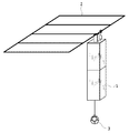
- FIG. 2 is a diagram showing the entire lighting device according to the first embodiment of the present invention.
- the lighting device according to the present invention includes a lighting lifting device 1, a suspension baton 2, and a lighting element 3.
- the lighting lifting device 1 is suspended from the suspension baton 2 with the upper end connected to the suspension baton 2.
- the lighting lifting / lowering device 1 is suspended in a state where the longitudinal direction is vertical.
- the illumination elevating device 1 rotates the reel with an electric motor installed therein, thereby winding the reel wire with the illumination element 3 attached to the reel and unwinding the reel 3 from the reel.
- the elevation of the illumination element 3 is controlled through software control by a control device (not shown) connected to the illumination elevation device 1.
- Susbaton 2 is a stage mechanism that is installed on the ceiling of the stage and suspends the lighting elevator 1.
- the suspension 2 is also a device having an outlet box in which a power outlet for connecting an appliance for connecting a power source of the lighting lifting device 1 is incorporated. Since the suspension baton 2 according to the present embodiment is a known one, detailed description thereof is omitted.
- the illumination element 3 is a light source that emits light from above the stage.
- the lighting element 3 is connected to a reel line and is suspended below the lighting lifting device 1.
- the illumination element 3 is an illumination element having an arbitrary shape, and a halogen light or an LED (Light-Emitting (Diode) is used. It is desirable that the lighting element 3 be lighter in consideration of the load on the suspension baton 2. Since the illumination element 3 according to the present embodiment is also known, further detailed description is omitted.
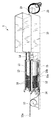
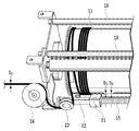
- the lighting lifting device 1 includes a housing 10, a reel 11, a reel wire 12, a winding guide 13, an electric motor 14, a guide screw 15, a clutch 16, a pulley 17, a support 18, a mounting portion 19, and a mounting hook 20.
- the housing 10 is a housing having a rectangular parallelepiped shape, covers the entire lighting lifting device 1, and has a structure that can be opened and closed as shown in FIG. 3. With this openable and closable structure, maintenance work such as replacement of the winding guide 13 installed inside the lighting lifting apparatus 1 can be facilitated.
- the housing 10 is preferably made of a lightweight material such as plastic or resin.
- the reel 11 has a cylindrical shape and is installed so that its longitudinal direction is parallel to the longitudinal direction of the housing 10.
- the reel 11 is connected to the electric motor 14, and rotates about the short axis by the operation of the electric motor 14. As the reel 11 rotates, the reel wire 12 is wound up by one layer winding, and the reverse rotation unwinds the reel wire 12.
- the reel 11 is preferably made of a lightweight material such as aluminum.
- the shape of the reel 11 is not limited to a cylindrical shape, and may be any equilateral equilateral shape such as a rectangle when viewed from the longitudinal direction and a square, a triangle, a pentagon, or a hexagon when viewed from the lateral direction. Good.
- the reel wire 12 has a connector 12a at the tip, and the lighting element 3 is attached via the connector 12a.
- the reel wire 12 protrudes downward from the lower part of the illumination lifting device 1. That is, the illumination element 3 attached to the tip of the reel wire 12 is suspended below the illumination lifting device 1.
- the winding guide 13 is a rotating body having a cylindrical shape.
- the winding guide 13 is installed so that its longitudinal direction is parallel to the longitudinal direction of the reel 11, and contacts the reel wire 12 wound around the reel 11.
- the winding guide 13 that comes into contact with the reel wire 12 wound around the reel 11 rotates in the reverse direction to the reel 11 around the axis in the short direction. Since the winding guide 13 is in contact with the reel wire 12, it is desirable that the winding guide 13 is made of an elastic material such as sponge, resin, or rubber in order to prevent the reel wire 12 from being damaged.
- the winding guide 13 is not limited to a cylindrical shape, and may be any equilateral equiangular shape such as a rectangle when viewed from the longitudinal direction and a square, a triangle, a pentagon, or a hexagon when viewed from the lateral direction. .
- the guide screw 15 is installed so that its longitudinal direction is parallel to the longitudinal direction of the reel 11, and rotates around an axis in the short direction in conjunction with the rotation of the reel 11 and / or the winding guide 13.
- the guide screw 15 has a guide ring 15a and a ring block 15b.
- the guide ring 15a is a rotating body having a cylindrical shape, and a guide screw 15 is inserted through the shaft hole.
- the ring block 15b is adjacent to the lower side of the guide ring 15a, and a guide screw 15 is inserted through the shaft hole thereof.
- the guide ring 15 a rotates in conjunction with the rotation of the guide screw 15 so that the longitudinal side surface of the guide ring 15 a faces the uppermost portion of the reel wire 12 wound around the reel 11 along the guide screw 15.
- the ring block 15b moves up and down in conjunction with the vertical movement of the guide ring 15a, and controls the downward movement of the guide ring 15a.
- the reel wire 12 follows the longitudinal side surface of the guide ring 15a, the clutch 16 and the pulley 17 along the rotation of the guide ring 15a, and protrudes through the lower part of the lighting lifting device 1.
- the reel wire 12 is wound around the reel 11 once.
- the clutch 16 is a rotating body installed at the lower part of the reel 11. The clutch 16 rotates according to the movement of the reel wire 12.
- the column 18 has a cylindrical shape and is installed so that the longitudinal direction thereof is parallel to the longitudinal direction of the reel 11, and supports the housing 10.
- the strut 18 also serves to prevent the reel wire 12 from being displaced and / or loosened, details of which will be described later.
- pillar 18 is not limited to a cylindrical shape, Arbitrary equilateral equilateral shapes, such as a rectangle seen from a longitudinal direction and a square, a triangle, a pentagon, or a hexagon seen from the transversal direction, may be sufficient.
- the mounting portion 19 has a screw type or bolt / nut type structure, and is a member that attaches the lighting lifting / lowering device 1 to the suspension baton 2.
- the lighting lifting device 1 is attached to the suspension baton 2 by the attachment portion 19 and is suspended from the suspension baton 2.
- the attachment hook 20 has a structure in which the hook and the wire are interlocked with each other, and plays a role of preventing the lighting elevating device 1 from falling from the suspension baton 2.
- the reel 11 has a reel wire winding surface 11a, and the reel wire 12 is wound around this portion.
- the winding guide 13 has a reel wire contact portion 13a, and this portion comes into contact with the reel wire 12 wound around the reel wire winding surface 11a as the winding guide 13 rotates.
- the winding guide 13 is configured by winding a member such as a sponge around a cylindrical core portion made of aluminum or the like.
- the reel 11 and the winding guide 13 are installed in parallel, and the reel winding surface 11a and the reel contact portion 13a face each other in the longitudinal direction.
- the reel wire contact portion 13a is configured to be at least the same or longer in the longitudinal direction than the reel wire winding surface 11a. That is, the reel wire contact portion 13a is configured to cover the entire facing surface of the reel wire winding surface 11a. With this configuration, all of the reel wires 12 wound on the reel wire winding surface 11a come into contact with the reel wire contact portion 13a.
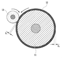
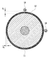
- FIG. 5 it is a cross-sectional view showing the relationship between the reel 11, the reel wire 12, and the winding guide 13 when the reel wire 12 is wound around the reel winding surface 11a.
- FIG. 5 shows a cross section when viewed from above in a state where the lighting lifting device 1 is suspended from the suspension baton 2.
- the reel 11 rotates counterclockwise around the axis of the short surface, and the reel wire 12 is wound around the reel wire winding surface 11a counterclockwise according to the rotation. .
- the winding guide 13 rotates clockwise in conjunction with the rotation of the reel 11.
- the reel 11 and the take-up guide 13 rotate reversely to each other, and the reel wire 12 passes between them.
- Distance D 1 of the between the reel 11 and the winding guide 13 is at least less diameter D r of the reel wire 12.
- the reel wire contact portion 13a of the winding guide 13 composed of a high and more elastic material, (to less than D r a D 1) by shortening the distance between the reel wire winding surface 11a, While maintaining smoothness when winding the reel wire 12, it is possible to more reliably prevent the reel wires 12 from overlapping.
- the reel 11 rotates counterclockwise, but the reel 11 may rotate clockwise.
- the winding guide 13 rotates counterclockwise, and both of them reversely rotate, thereby preventing the reel wires 12 from overlapping.
- either or both of the reel 11 and the take-up guide 13 are rectangular when viewed from the longitudinal direction, square, triangular, pentagonal, or hexagonal when viewed from the lateral direction. Even if it has, the effect similar to the effect mentioned above can be acquired. In this case, it is necessary that both the reel 11 and the winding guide 13 have the same shape and area, and that the corners of both are in contact with the reel wire 12 at the same time. Further, when either the reel 11 or the winding guide 13 has a cylindrical shape, the same effect as described above can be obtained by making the other an equilateral isometric shape.
- the support column 18 is installed in parallel with the reel 11 and faces the reel winding surface 11a in the longitudinal direction.
- the support column 18 is configured to be at least the same or longer in the longitudinal direction than the reel wire winding surface 11a. That is, the support column 18 is configured to cover the entire facing surface of the reel winding surface 11a. With this configuration, all of the reel wire 12 wound on the reel wire winding surface 11 a passes between the reel wire contact portion 13 a and the support column 18.
- FIG. 7 shows a cross section when viewed from above in a state where the lighting lifting device 1 is suspended from the suspension baton 2.
- the diameter D r of the distance D 2 As shown in FIG. 7, the diameter D r of the distance D 2, and the reel wire 12 between the reel 11 and the post 18, satisfies the following relationship.
- the distance D 2 between the reels line winding surface 11a and the support 18 is longer than the diameter D r of the reel wire 12, reel line 12 is wound on the reel wire winding surface 11a is struts 18 does not touch.
- wear due to the reel wire 12 coming into contact with the support column 18 can be prevented.
- the distance D 2 between the reels line winding surface 11a and the support 18 is less than twice the diameter D r of the reel wire 12, overlapping the reel wire 12 is wound on the reel wire winding face 11a Absent.
- the overlapping of the reel wires 12 can be prevented more reliably.
- the number of the support columns 18 is not particularly limited, but it is desirable that a plurality of the columns 10 be arranged in consideration of covering the entire lighting lifting device 1. By arranging a plurality of columns 18, it is possible to more reliably prevent the reel wires 12 from overlapping.
- the lighting lifting apparatus 1 is hung on the suspension baton 2 in a state where the longitudinal direction is vertical, and the lighting element 3 connected to the reel wire 12 is hung below the lighting lifting apparatus 1. It is.
- the reel wire 12 is suspended below the lighting lifting device 1 in a state where gravity is applied by the weight of the reel wire 12 and the weight of the connected lighting element 3.
- the reel 11, the winding guide 13, the guide screw 15, and the support column 18 are each in a state where the longitudinal direction is vertical.
- the reel 11, the winding guide 13, the guide screw 15, and the column 18 are installed in parallel, and are opposed to each other in the longitudinal direction.
- the guide ring 15a moves up and down so as to face the uppermost part of the reel wire 12 wound around the reel wire winding surface 11a.
- the reel wire 12 is wound through the guide ring 15a in the lateral direction on the reel wire winding surface 11a and from the lower side to the upper side of the reel wire winding surface 11a.
- the reel wire 12 does not overlap when winding due to the above-described functions of the winding guide 13 and the column 18. Then, since the gravity is applied to the reel wire 12, when the reel wire 12 is wound, it is attracted to the adjacent reel wire 12 by the gravity, and the above-described deviation does not occur. Further, since the guide ring 15a moves up and down in accordance with the winding of the reel wire 12, the reel wire 12 can be taken up regularly.
- the lighting lifting / lowering apparatus 1 has a simple and lightweight structure, and can prevent the deviation and / or slack of the reel wire.
- the clutch 16 may employ a one-way clutch such as a sprag type or a cam type.
- the clutch 16 rotates only when the reel wire 12 is guided downward (that is, when the reel wire 12 is unwound and the lighting element 3 is lowered), and when the reel wire 12 is guided upward ( In other words, the reel wire 12 may be wound up so that it does not rotate (when the lighting element 3 is raised).
- the structure mentioned above is not essential.
- the reel wires 12 are prevented from overlapping only by the function of the winding guide 13.
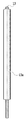
- the illumination lifting apparatus 1 has a difference in the guide screw 15 compared to the illumination lifting apparatus according to the first embodiment.
- the guide screw 15 includes a guide block 21, a lower portion thereof includes a reel wire fixing portion 22, and a lower portion thereof includes a guide ring 23.
- the guide block 21 has a surface facing the reel winding surface 11a.
- the guide screw 15 is inserted into the shaft hole of the guide block 21 and moves up and down along the guide screw 15 in conjunction with the rotation of the guide screw 15. This vertical movement is configured to be interlocked with the winding of the reel wire 12 onto the reel wire winding surface 11a. Between the opposing surfaces of the reel wire winding surface 11a and the guide block 21 has a slight clearance, the distance D 3 of the clearance is less than the diameter D r of the reel wire 12.
- the reel wire fixing portion 22 protrudes from a guide screw 15 installed in parallel with the reel 11 and opposes the lower portion of the reel wire winding surface 11a of the reel 11 in the longitudinal direction. Between the reel wire winding surface 11a and the reel wire fixing portion 22 has the slight clearance, the distance D 4 of the gap is less than the diameter D r of the reel wire 12.
- the guide ring 23 is installed below the reel wire fixing portion 22 of the guide screw 15 and guides the reel wire 12 guided from the pulley 17.
- the reel wire 12 is guided upward along the curved surface of the guide ring 23 and between the reel wire fixing portion 22 and the guide block 21.
- the reel wire 12 is wound on the reel wire winding surface 11a in conjunction with the upward movement of the guide block 21 with the winding start portion fixed below by the reel wire fixing portion 22. In this way, since the starting point when winding the reel wire 12 is fixed, the slack of the reel wire during winding can be further prevented. Further, since the reel wire 12 is wound up in conjunction with the upward movement of the guide block 21, the reel wire 12 can be taken up regularly.
- reel wire fixing portion 22 and the guide ring 23 are installed on the guide screw 15
- the present invention is not limited to such a configuration.
- the reel wire fixing portion 22 and the guide ring 23 may be installed on the support column 18 in the same manner as described above.
- the reel wire fixing portion 22 may be installed on the guide screw 15 and the guide ring 23 may be installed on the support column 18, and vice versa.
- the present invention is not limited to such an example.
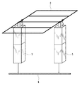
- a rectangular (bar-shaped) lighting element device 4 in which a plurality of lighting elements are incorporated may be suspended by a plurality of lighting lifting devices 1 (third embodiment).
- a plurality of lighting lifting devices 1 third embodiment.
- a light source (not shown) is installed on the ceiling or the like of the stage, the mirror 5 is irradiated with light from the lighting device, and the mirror 5 is moved up and down, which again differs from the configuration described in the embodiment. Can be created.
- a combination of a plurality of the above-described lighting element 3, lighting element device 4, and mirror is hung by a plurality of lighting lifting devices 1 and their lifting / lowering is controlled (by software control), thereby producing a more effective performance.
- a three-dimensional effect can be created by raising and lowering each of the plurality of combinations described above over time.
Landscapes
- Engineering & Computer Science (AREA)
- General Engineering & Computer Science (AREA)
- Mechanical Engineering (AREA)
- Non-Portable Lighting Devices Or Systems Thereof (AREA)
- Storing, Repeated Paying-Out, And Re-Storing Of Elongated Articles (AREA)
Abstract
Description
図2は、本発明の第1の実施形態に従った、照明装置全体を示す図である。本発明に係る照明装置は、照明昇降装置1、サスバトン2、および照明素子3を備える。照明昇降装置1は、上端がサスバトン2に連結されて、サスバトン2に吊るされる。図2に示すように、照明昇降装置1は、長手方向を縦にした状態で吊るされる。照明昇降装置1は、内部に設置された電動モータでリールを回転させることによって、照明素子3が取り付けられたリール線をリールに巻き取り、およびリールから巻き解くことによって照明素子3を昇降させる。照明素子3の昇降は、照明昇降装置1に接続された制御装置(図示せず)によるソフトウェア制御を通じて制御される。
次に、図9を参照して、本発明の第2の実施形態に係る照明昇降装置1を説明する。本実施形態に係る照明昇降装置1は、第1の実施形態に係る照明昇降装置と比較して、ガイドネジ15に相違点を有する。図9に示すように、ガイドネジ15はガイドブロック21を備え、その下部には、リール線固定部22を備え、さらにその下部には、ガイドリング23を備える。
2 サスバトン
3 照明素子
4 照明素子装置
5 鏡
10 筐体
11 リール
11a リール線巻取面
12 リール線
12a コネクタ
13 巻取ガイド
13a リール線接触部
14 電動モータ
15 ガイドネジ
15a ガイドリング
15b リングブロック
16 クラッチ
17 滑車
18 支柱
19 取付部
20 取付フック
21 ガイドブロック
22 リール線固定部
23 ガイドリング
Claims (5)
- 照明昇降装置であって、
リール線巻取面を含み、長手方向を縦にした状態で設置されたリールであって、前記リールは、電動モータと連結し、前記電動モータによって短手方向の面の軸を中心に回転する、リールと、
前記リールの回転によって、前記リール線巻取面に巻き取られるリール線と、
前記リール線巻取面と対向したリール線接触部を含み、前記リールと平行して設置された巻取ガイドであって、前記リール線巻取面と前記リール線接触部との間の距離は、前記リール線の直径以下である、巻取ガイドと、
前記リール線の先端に取り付けられ、前記照明昇降装置の下方に吊るされる被昇降物を接続するためのコネクタと
を備え、
前記巻取ガイドは、前記リールの回転に沿って逆回転し、
前記リール線は、前記リール線巻取面と前記リール線接触部との間を通る
ことを特徴とする照明昇降装置。 - 前記リール線巻取面と対向し、前記リール線を案内するガイドリングを含み、前記リールと平行して設置されたガイドネジをさらに備え、
前記ガイドネジは、前記リールの回転と連動して回転し、前記ガイドリングの軸孔に挿通され、
前記ガイドリングは、前記ガイドネジの回転と連動して回転して、前記リール線巻取面に巻き取られた前記リール線の最上部と対向するように前記ガイドネジに沿って上下移動する
ことを特徴とする請求項1に記載の照明昇降装置。 - 前記リール線巻取面と対向したリール線固定部およびガイドブロックを含み、前記リールと平行して設置されたガイドネジをさらに備え、
前記リール線固定部は、前記ガイドネジの下方に設置され、前記リール線巻取面の長手方向の下部と対向し、
前記ガイドネジは、前記リールの回転と連動して回転して、前記ガイドブロックの軸孔に挿通され、
前記ガイドブロックは、前記ガイドネジの回転と連動して、前記ガイドネジに沿って上下移動し、
前記リール線巻取面と前記リール線固定部との間の距離は、前記リール線の直径未満であり、
前記リール線は、前記リール線巻取面に巻き取られるときに、前記リール線固定部と前記ガイドブロックの間を通って前記リール線巻取面の下方から上方に向かって案内される
ことを特徴とする請求項1に記載の照明昇降装置。 - 前記リール線巻取面と対向し、前記リールと平行して設置された支柱をさらに備え、
前記リール線巻取面と前記支柱との間の距離は、前記リール線の直径以上であり、かつ前記リール線の直径の2倍未満である
ことを特徴とする請求項1乃至3のいずれか一項に記載の照明昇降装置。 - 前記リールの下方に設置され、前記リール線が接触することによって回転するクラッチをさらに備え、
前記リール線は、前記クラッチに沿って前記照明昇降装置の下方に案内され、
前記クラッチは、
前記リール線が前記リール線巻取面から巻き解かれるときに、前記リール線の動きに沿って回転し、
前記リール線が前記リール線巻取面から巻き取られるときに、前記リール線の動きに沿って回転しない
ことを特徴とする請求項1乃至4のいずれか一項に記載の照明昇降装置。
Priority Applications (4)
| Application Number | Priority Date | Filing Date | Title |
|---|---|---|---|
| EP17785954.3A EP3447373A4 (en) | 2016-04-21 | 2017-04-17 | LIFTING / LOWERING DEVICE FOR LIGHTING |
| US16/093,700 US10502401B2 (en) | 2016-04-21 | 2017-04-17 | Lighting elevating apparatus |
| CA3021627A CA3021627A1 (en) | 2016-04-21 | 2017-04-17 | Lighting elevating apparatus |
| US16/670,288 US10683997B2 (en) | 2016-04-21 | 2019-10-31 | Illumination raising/lowering device |
Applications Claiming Priority (2)
| Application Number | Priority Date | Filing Date | Title |
|---|---|---|---|
| JP2016-085538 | 2016-04-21 | ||
| JP2016085538A JP6142374B1 (ja) | 2016-04-21 | 2016-04-21 | 照明昇降装置 |
Related Child Applications (2)
| Application Number | Title | Priority Date | Filing Date |
|---|---|---|---|
| US16/093,700 A-371-Of-International US10502401B2 (en) | 2016-04-21 | 2017-04-17 | Lighting elevating apparatus |
| US16/670,288 Division US10683997B2 (en) | 2016-04-21 | 2019-10-31 | Illumination raising/lowering device |
Publications (1)
| Publication Number | Publication Date |
|---|---|
| WO2017183616A1 true WO2017183616A1 (ja) | 2017-10-26 |
Family
ID=58334036
Family Applications (1)
| Application Number | Title | Priority Date | Filing Date |
|---|---|---|---|
| PCT/JP2017/015511 WO2017183616A1 (ja) | 2016-04-21 | 2017-04-17 | 照明昇降装置 |
Country Status (11)
| Country | Link |
|---|---|
| US (2) | US10502401B2 (ja) |
| EP (1) | EP3447373A4 (ja) |
| JP (1) | JP6142374B1 (ja) |
| KR (2) | KR101793521B1 (ja) |
| CN (3) | CN107859977B (ja) |
| AU (2) | AU2017202602B1 (ja) |
| CA (1) | CA3021627A1 (ja) |
| MY (1) | MY178457A (ja) |
| SG (2) | SG10201703215VA (ja) |
| TW (2) | TWI603031B (ja) |
| WO (1) | WO2017183616A1 (ja) |
Cited By (1)
| Publication number | Priority date | Publication date | Assignee | Title |
|---|---|---|---|---|
| WO2019124501A1 (ja) * | 2017-12-20 | 2019-06-27 | 株式会社Isa | 三次元演出方法、三次元演出システムおよび昇降装置 |
Families Citing this family (13)
| Publication number | Priority date | Publication date | Assignee | Title |
|---|---|---|---|---|
| CN108989742B (zh) * | 2017-05-31 | 2021-07-13 | 广州市震泓科技股份有限公司 | 基于照明平台的多功能安防设备 |
| JP6371447B1 (ja) * | 2017-07-07 | 2018-08-08 | 株式会社Isa | 昇降装置 |
| JP6516798B2 (ja) * | 2017-07-18 | 2019-05-22 | 株式会社Isa | 昇降装置 |
| CN108278565B (zh) * | 2017-12-28 | 2019-12-13 | 广州歌斯达舞台灯光设备有限公司 | 舞台灯的升降装置 |
| US10683996B1 (en) | 2019-05-28 | 2020-06-16 | Isa Co., Ltd. | Illumination system and illumination method |
| JP6619903B1 (ja) | 2019-05-28 | 2019-12-11 | 株式会社Isa | 照明システムおよび照明方法 |
| CN111924670A (zh) * | 2020-07-24 | 2020-11-13 | 西安环海机器人科技有限公司 | 自动收放线机构 |
| KR102527192B1 (ko) * | 2022-05-03 | 2023-05-02 | 주식회사 화신이앤비 | 높이 조절이 가능한 승하강식 조명탑 |
| GB2620425B (en) * | 2022-07-07 | 2024-10-30 | Albright Product Design Ltd | Cable tensioning assembly and cable reel assembly |
| US11937581B2 (en) | 2022-08-01 | 2024-03-26 | Peco Foods, Inc. | Lighting system for poultry houses |
| CN115388390B (zh) * | 2022-08-23 | 2023-04-28 | 湖南明和科技工程发展有限公司 | 舞台灯控制系统用多功能调整平台 |
| DE202022106657U1 (de) * | 2022-11-28 | 2024-03-01 | Paul Neuhaus Gmbh | Leuchte |
| CN116442914B (zh) * | 2023-06-15 | 2023-10-27 | 国网山西省电力公司信息通信分公司 | 一种多功能通信车 |
Citations (4)
| Publication number | Priority date | Publication date | Assignee | Title |
|---|---|---|---|---|
| JPH07211127A (ja) | 1994-01-10 | 1995-08-11 | Matsushita Electric Works Ltd | 昇降式照明器具 |
| JP2008091152A (ja) * | 2006-09-29 | 2008-04-17 | Matsushita Electric Works Ltd | 照明用昇降装置 |
| JP2008257961A (ja) * | 2007-04-03 | 2008-10-23 | Isa:Kk | 三次元演出方法およびシステム |
| EP2985742A1 (en) * | 2014-08-12 | 2016-02-17 | Wills, Colin Peter | A ceiling mount assembly |
Family Cites Families (27)
| Publication number | Priority date | Publication date | Assignee | Title |
|---|---|---|---|---|
| US2348987A (en) * | 1940-01-24 | 1944-05-16 | Yale & Towne Mfg Co | Hoist |
| US3809334A (en) * | 1972-11-06 | 1974-05-07 | United Aircraft Corp | Winch system for helicopter |
| US4150801A (en) * | 1975-10-30 | 1979-04-24 | Kobe Steel, Ltd. | Automatic winding machine for wire-like object |
| US4087060A (en) * | 1976-10-12 | 1978-05-02 | Breeze Corporations, Inc. | Self level wind cable storage reel |
| CA1096369A (en) * | 1979-08-02 | 1981-02-24 | Robert S. Norminton | Compact cross-shaft type compound drum hoist for spooling extra long lenghts of tow cable with segmental fairings |
| US4746100A (en) * | 1986-12-24 | 1988-05-24 | Caterpillar Inc. | Winch drag brake apparatus |
| JPH0388697A (ja) * | 1989-08-31 | 1991-04-15 | Toshiba Lighting & Technol Corp | 昇降装置 |
| US6435447B1 (en) * | 2000-02-24 | 2002-08-20 | Halliburton Energy Services, Inc. | Coil tubing winding tool |
| JP4540212B2 (ja) | 2000-10-24 | 2010-09-08 | 田中電子工業株式会社 | ボンディングワイヤの巻替ガイド及びそれを用いた巻替方法 |
| JP2005075615A (ja) * | 2003-09-03 | 2005-03-24 | Toshiba Lighting & Technology Corp | 昇降装置 |
| KR20050035346A (ko) * | 2003-10-13 | 2005-04-18 | 협우물산 주식회사 | 호스 자동 감김 및 인출장치를 갖는 생력형 방제시스템 |
| WO2007120009A1 (en) * | 2006-04-17 | 2007-10-25 | Jeong-Hun Shin | Lifting apparatus having lifting reel |
| KR100780165B1 (ko) * | 2006-04-17 | 2007-11-27 | 신정훈 | 천정형 공기조화기의 그릴 승강기 |
| KR100779356B1 (ko) * | 2006-11-13 | 2007-11-23 | 신정훈 | 전류의 흐름을 이용한 승강릴 관리 장치 |
| KR101056847B1 (ko) | 2008-10-10 | 2011-08-22 | (주)엔티전기 | 고소조명 승강장치 |
| CN201362568Y (zh) * | 2008-12-26 | 2009-12-16 | 佑图物理应用科技发展(武汉)有限公司 | 一种舞台用可调吊点方向的单点吊机 |
| US8517348B2 (en) | 2010-02-05 | 2013-08-27 | Frederick L. Smith | Windlass system and method |
| US9908757B2 (en) * | 2010-03-08 | 2018-03-06 | Wizard Products, Llc | Gas powered self contained portable winch |
| AU2010224459B2 (en) * | 2010-09-29 | 2016-05-05 | Harry Xydias | Level wind assembly for a winch drum including a tensioning arm |
| CN202265354U (zh) * | 2011-07-24 | 2012-06-06 | 安徽省精英机械制造有限公司 | 一种新型舞台吊机 |
| CN102359725A (zh) * | 2011-10-18 | 2012-02-22 | 张景昭 | 一种带绕线器的灯具 |
| TWM440384U (en) * | 2012-07-02 | 2012-11-01 | Dong-You Lan | Improved lamp post structure |
| KR20140147224A (ko) * | 2013-06-19 | 2014-12-30 | 신정훈 | 베어링 타입 와이어 권취 드럼을 갖는 승강릴 |
| FI126273B (fi) * | 2014-01-24 | 2016-09-15 | Konecranes Global Oy | Köysinostimen matalarakenteinen nostovaunu |
| CN204057805U (zh) * | 2014-05-26 | 2014-12-31 | 北京北特圣迪科技发展有限公司 | 一种自动排绳式灯光吊杆卷扬机 |
| US10093522B1 (en) * | 2015-11-18 | 2018-10-09 | Reel Power Licensing Corp. | Reversing leadscrew apparatus, system and method |
| US10112809B2 (en) * | 2016-02-25 | 2018-10-30 | Hall Labs Llc | Reliable spooling for a motorized lifting/pulling device |
-
2016
- 2016-04-21 JP JP2016085538A patent/JP6142374B1/ja active Active
- 2016-12-09 TW TW105140892A patent/TWI603031B/zh active
- 2016-12-09 TW TW106128140A patent/TWI618888B/zh not_active IP Right Cessation
- 2016-12-22 KR KR1020160176545A patent/KR101793521B1/ko active Application Filing
- 2016-12-26 CN CN201711101234.5A patent/CN107859977B/zh not_active Expired - Fee Related
- 2016-12-26 CN CN201611215332.7A patent/CN106500068B/zh active Active
- 2016-12-26 CN CN201621440043.2U patent/CN206555962U/zh not_active Expired - Fee Related
-
2017
- 2017-04-17 CA CA3021627A patent/CA3021627A1/en not_active Abandoned
- 2017-04-17 US US16/093,700 patent/US10502401B2/en active Active
- 2017-04-17 EP EP17785954.3A patent/EP3447373A4/en not_active Withdrawn
- 2017-04-17 WO PCT/JP2017/015511 patent/WO2017183616A1/ja active Application Filing
- 2017-04-17 MY MYPI2017701359A patent/MY178457A/en unknown
- 2017-04-19 SG SG10201703215VA patent/SG10201703215VA/en unknown
- 2017-04-19 SG SG10201709946TA patent/SG10201709946TA/en unknown
- 2017-04-19 AU AU2017202602A patent/AU2017202602B1/en active Active
- 2017-06-10 AU AU2017203944A patent/AU2017203944B2/en active Active
- 2017-10-16 KR KR1020170134033A patent/KR101872365B1/ko active IP Right Grant
-
2019
- 2019-10-31 US US16/670,288 patent/US10683997B2/en active Active
Patent Citations (5)
| Publication number | Priority date | Publication date | Assignee | Title |
|---|---|---|---|---|
| JPH07211127A (ja) | 1994-01-10 | 1995-08-11 | Matsushita Electric Works Ltd | 昇降式照明器具 |
| JP2008091152A (ja) * | 2006-09-29 | 2008-04-17 | Matsushita Electric Works Ltd | 照明用昇降装置 |
| JP2008257961A (ja) * | 2007-04-03 | 2008-10-23 | Isa:Kk | 三次元演出方法およびシステム |
| JP5173231B2 (ja) | 2007-04-03 | 2013-04-03 | 株式会社Isa | 三次元演出方法およびシステム |
| EP2985742A1 (en) * | 2014-08-12 | 2016-02-17 | Wills, Colin Peter | A ceiling mount assembly |
Non-Patent Citations (1)
| Title |
|---|
| See also references of EP3447373A4 |
Cited By (2)
| Publication number | Priority date | Publication date | Assignee | Title |
|---|---|---|---|---|
| WO2019124501A1 (ja) * | 2017-12-20 | 2019-06-27 | 株式会社Isa | 三次元演出方法、三次元演出システムおよび昇降装置 |
| JP2019110946A (ja) * | 2017-12-20 | 2019-07-11 | 株式会社Isa | 三次元演出方法、三次元演出システムおよび昇降装置 |
Also Published As
| Publication number | Publication date |
|---|---|
| EP3447373A1 (en) | 2019-02-27 |
| SG10201703215VA (en) | 2017-11-29 |
| CA3021627A1 (en) | 2017-10-26 |
| KR101793521B1 (ko) | 2017-11-20 |
| AU2017203944A1 (en) | 2017-07-06 |
| US10502401B2 (en) | 2019-12-10 |
| TW201809544A (zh) | 2018-03-16 |
| AU2017202602B1 (en) | 2017-05-25 |
| US20190078765A1 (en) | 2019-03-14 |
| AU2017203944B2 (en) | 2018-04-12 |
| KR20170120535A (ko) | 2017-10-31 |
| TW201741595A (zh) | 2017-12-01 |
| MY178457A (en) | 2020-10-13 |
| JP6142374B1 (ja) | 2017-06-07 |
| CN106500068B (zh) | 2018-03-09 |
| JP2017195119A (ja) | 2017-10-26 |
| CN107859977B (zh) | 2019-10-11 |
| US20200063950A1 (en) | 2020-02-27 |
| KR20170120482A (ko) | 2017-10-31 |
| CN106500068A (zh) | 2017-03-15 |
| EP3447373A4 (en) | 2019-09-18 |
| TWI618888B (zh) | 2018-03-21 |
| SG10201709946TA (en) | 2018-01-30 |
| TWI603031B (zh) | 2017-10-21 |
| US10683997B2 (en) | 2020-06-16 |
| CN206555962U (zh) | 2017-10-13 |
| KR101872365B1 (ko) | 2018-08-02 |
| CN107859977A (zh) | 2018-03-30 |
Similar Documents
| Publication | Publication Date | Title |
|---|---|---|
| JP6142374B1 (ja) | 照明昇降装置 | |
| TWI603032B (zh) | 高處安裝設備用之升降裝置 | |
| US9962621B2 (en) | Compact hoist system | |
| KR101416795B1 (ko) | 연등 리프팅 장치 | |
| KR102151698B1 (ko) | 와이어로프 장력조절 및 이탈을 방지하는 무대시설용 안전 장치 | |
| JP6186607B1 (ja) | 照明昇降装置 | |
| JP2019018968A (ja) | 昇降装置 | |
| JP2010170875A (ja) | 昇降式照明器具 | |
| KR20220100221A (ko) | 바튼 승하강 장치의 와이어 로프 안전 가이드 장치. | |
| JPH08310790A (ja) | 電動昇降装置 | |
| KR20200047163A (ko) | 안내유도장치가 구비된 무대시설용 안전 승하강장치 | |
| JP2010118219A (ja) | 電動昇降装置および昇降式照明装置 | |
| KR960000663Y1 (ko) | 유선마이크 승강장치 | |
| JP2004256279A (ja) | 昇降装置 | |
| JP2000011710A (ja) | 照明灯 | |
| JPH07211127A (ja) | 昇降式照明器具 | |
| JPH04107788U (ja) | 電動昇降装置 | |
| JPH04140300A (ja) | 昇降装置 | |
| JP2002274785A (ja) | 昇降装置 | |
| JP2012171706A (ja) | 巻き上げ装置 |
Legal Events
| Date | Code | Title | Description |
|---|---|---|---|
| ENP | Entry into the national phase |
Ref document number: 3021627 Country of ref document: CA |
|
| NENP | Non-entry into the national phase |
Ref country code: DE |
|
| WWE | Wipo information: entry into national phase |
Ref document number: 2017785954 Country of ref document: EP |
|
| ENP | Entry into the national phase |
Ref document number: 2017785954 Country of ref document: EP Effective date: 20181121 |
|
| 121 | Ep: the epo has been informed by wipo that ep was designated in this application |
Ref document number: 17785954 Country of ref document: EP Kind code of ref document: A1 |