WO2017183446A1 - 表示装置 - Google Patents
表示装置 Download PDFInfo
- Publication number
- WO2017183446A1 WO2017183446A1 PCT/JP2017/014137 JP2017014137W WO2017183446A1 WO 2017183446 A1 WO2017183446 A1 WO 2017183446A1 JP 2017014137 W JP2017014137 W JP 2017014137W WO 2017183446 A1 WO2017183446 A1 WO 2017183446A1
- Authority
- WO
- WIPO (PCT)
- Prior art keywords
- light
- filter
- display device
- laser
- dimming
- Prior art date
- Legal status (The legal status is an assumption and is not a legal conclusion. Google has not performed a legal analysis and makes no representation as to the accuracy of the status listed.)
- Ceased
Links
Images




Classifications
-
- G—PHYSICS
- G09—EDUCATION; CRYPTOGRAPHY; DISPLAY; ADVERTISING; SEALS
- G09G—ARRANGEMENTS OR CIRCUITS FOR CONTROL OF INDICATING DEVICES USING STATIC MEANS TO PRESENT VARIABLE INFORMATION
- G09G5/00—Control arrangements or circuits for visual indicators common to cathode-ray tube indicators and other visual indicators
- G09G5/10—Intensity circuits
-
- G—PHYSICS
- G02—OPTICS
- G02B—OPTICAL ELEMENTS, SYSTEMS OR APPARATUS
- G02B26/00—Optical devices or arrangements for the control of light using movable or deformable optical elements
- G02B26/02—Optical devices or arrangements for the control of light using movable or deformable optical elements for controlling the intensity of light
- G02B26/023—Optical devices or arrangements for the control of light using movable or deformable optical elements for controlling the intensity of light comprising movable attenuating elements, e.g. neutral density filters
-
- G—PHYSICS
- G02—OPTICS
- G02B—OPTICAL ELEMENTS, SYSTEMS OR APPARATUS
- G02B27/00—Optical systems or apparatus not provided for by any of the groups G02B1/00 - G02B26/00, G02B30/00
- G02B27/01—Head-up displays
- G02B27/017—Head mounted
- G02B27/0172—Head mounted characterised by optical features
-
- G—PHYSICS
- G09—EDUCATION; CRYPTOGRAPHY; DISPLAY; ADVERTISING; SEALS
- G09G—ARRANGEMENTS OR CIRCUITS FOR CONTROL OF INDICATING DEVICES USING STATIC MEANS TO PRESENT VARIABLE INFORMATION
- G09G3/00—Control arrangements or circuits, of interest only in connection with visual indicators other than cathode-ray tubes
- G09G3/001—Control arrangements or circuits, of interest only in connection with visual indicators other than cathode-ray tubes using specific devices not provided for in groups G09G3/02 - G09G3/36, e.g. using an intermediate record carrier such as a film slide; Projection systems; Display of non-alphanumerical information, solely or in combination with alphanumerical information, e.g. digital display on projected diapositive as background
-
- G—PHYSICS
- G09—EDUCATION; CRYPTOGRAPHY; DISPLAY; ADVERTISING; SEALS
- G09G—ARRANGEMENTS OR CIRCUITS FOR CONTROL OF INDICATING DEVICES USING STATIC MEANS TO PRESENT VARIABLE INFORMATION
- G09G3/00—Control arrangements or circuits, of interest only in connection with visual indicators other than cathode-ray tubes
- G09G3/02—Control arrangements or circuits, of interest only in connection with visual indicators other than cathode-ray tubes by tracing or scanning a light beam on a screen
- G09G3/025—Control arrangements or circuits, of interest only in connection with visual indicators other than cathode-ray tubes by tracing or scanning a light beam on a screen with scanning or deflecting the beams in two directions or dimensions
-
- H—ELECTRICITY
- H04—ELECTRIC COMMUNICATION TECHNIQUE
- H04N—PICTORIAL COMMUNICATION, e.g. TELEVISION
- H04N5/00—Details of television systems
- H04N5/74—Projection arrangements for image reproduction, e.g. using eidophor
- H04N5/7475—Constructional details of television projection apparatus
- H04N5/7491—Constructional details of television projection apparatus of head mounted projectors
-
- G—PHYSICS
- G02—OPTICS
- G02B—OPTICAL ELEMENTS, SYSTEMS OR APPARATUS
- G02B27/00—Optical systems or apparatus not provided for by any of the groups G02B1/00 - G02B26/00, G02B30/00
- G02B27/01—Head-up displays
- G02B27/0101—Head-up displays characterised by optical features
- G02B2027/0118—Head-up displays characterised by optical features comprising devices for improving the contrast of the display / brillance control visibility
-
- G—PHYSICS
- G02—OPTICS
- G02B—OPTICAL ELEMENTS, SYSTEMS OR APPARATUS
- G02B26/00—Optical devices or arrangements for the control of light using movable or deformable optical elements
- G02B26/08—Optical devices or arrangements for the control of light using movable or deformable optical elements for controlling the direction of light
- G02B26/0816—Optical devices or arrangements for the control of light using movable or deformable optical elements for controlling the direction of light by means of one or more reflecting elements
- G02B26/0833—Optical devices or arrangements for the control of light using movable or deformable optical elements for controlling the direction of light by means of one or more reflecting elements the reflecting element being a micromechanical device, e.g. a MEMS mirror, DMD
- G02B26/0858—Optical devices or arrangements for the control of light using movable or deformable optical elements for controlling the direction of light by means of one or more reflecting elements the reflecting element being a micromechanical device, e.g. a MEMS mirror, DMD the reflecting means being moved or deformed by piezoelectric means
-
- G—PHYSICS
- G02—OPTICS
- G02B—OPTICAL ELEMENTS, SYSTEMS OR APPARATUS
- G02B26/00—Optical devices or arrangements for the control of light using movable or deformable optical elements
- G02B26/08—Optical devices or arrangements for the control of light using movable or deformable optical elements for controlling the direction of light
- G02B26/10—Scanning systems
- G02B26/105—Scanning systems with one or more pivoting mirrors or galvano-mirrors
-
- G—PHYSICS
- G09—EDUCATION; CRYPTOGRAPHY; DISPLAY; ADVERTISING; SEALS
- G09G—ARRANGEMENTS OR CIRCUITS FOR CONTROL OF INDICATING DEVICES USING STATIC MEANS TO PRESENT VARIABLE INFORMATION
- G09G2320/00—Control of display operating conditions
- G09G2320/06—Adjustment of display parameters
- G09G2320/0626—Adjustment of display parameters for control of overall brightness
-
- G—PHYSICS
- G09—EDUCATION; CRYPTOGRAPHY; DISPLAY; ADVERTISING; SEALS
- G09G—ARRANGEMENTS OR CIRCUITS FOR CONTROL OF INDICATING DEVICES USING STATIC MEANS TO PRESENT VARIABLE INFORMATION
- G09G2360/00—Aspects of the architecture of display systems
- G09G2360/14—Detecting light within display terminals, e.g. using a single or a plurality of photosensors
- G09G2360/144—Detecting light within display terminals, e.g. using a single or a plurality of photosensors the light being ambient light
-
- H—ELECTRICITY
- H04—ELECTRIC COMMUNICATION TECHNIQUE
- H04N—PICTORIAL COMMUNICATION, e.g. TELEVISION
- H04N5/00—Details of television systems
- H04N5/64—Constructional details of receivers, e.g. cabinets or dust covers
Definitions
- the present invention relates to a display device.
- a display device is known that is mounted on the user's head and allows the user to view a predetermined image.
- a display device that can project an image by laser light relatively clearly even in an environment where the surroundings are bright by placing a neutral density filter against external light (see, for example, Patent Document 1).
- surrounding information other than the laser light is blocked.
- the information by the laser light overlaps the surrounding environment, such as during walking, driving, or work support.
- Application may be difficult to apply.
- the present invention has been made in view of the above points, and an object of the present invention is to provide a display device that allows a user to obtain information based on a projected image without losing information obtained from the surrounding environment. .
- the display device (1) is a display device (1) that is mounted on the user's head and allows the user to view a predetermined image, and includes a light amount detection means (17) that detects the amount of external light.
- a light-reducing means (211R, 211G, 211B) that emits a laser beam having a light amount corresponding to the current value and a filter (221 to 227) that can switch the light-reduction ratio, 22)
- an optical scanning unit (15) that scans the laser light transmitted through the filters (221 to 227)
- a projection optical system (16) that projects the scanned laser light to form an image
- Control means for controlling the luminance of the video by increasing or decreasing the current value and switching the dimming ratio of the filters (221 to 227) based on the light quantity of the external light detected by the light quantity detection means (17). 27) and having And requirements.
- FIG. 1 is a perspective view illustrating the appearance of a display device according to an embodiment; It is a schematic diagram which illustrates the projection optical system of the display apparatus which concerns on this Embodiment. It is an example of the block diagram explaining the control apparatus which concerns on this Embodiment. It is a schematic diagram which illustrates the structure of the neutral density filter which concerns on this Embodiment. It is a figure which shows an example of the relationship between the input current of a laser, and optical output (light quantity). It is a figure explaining the adjustment of a brightness
- FIG. 1 is a perspective view illustrating the appearance of a display device according to this embodiment.
- FIG. 2 is a schematic view illustrating the projection optical system of the display device according to this embodiment.
- the display device 1 shown in FIGS. 1 and 2 is a retinal scanning head-mounted display that directly projects an image on the retina of the user's eye.
- the display device 1 can be used, for example, as a device that allows a user to visually recognize work support information recorded in advance in a database or the like.
- the display device 1 can be used as a device in which a camera module is provided and information obtained by the camera module is visually recognized by the user.
- an apparatus having both functions may be used.
- the display device 1 includes, as main components, a mounting unit 10 that can be mounted on the head of a user (wearer), and a control box 20B that includes a control device 20 (described later) that controls the mounting unit 10. is doing.
- the control box 20B is, for example, a rectangular parallelepiped housing, and can be provided with various switches, a display unit, and the like as necessary.
- the mounting unit 10 and the control device 20 in the control box 20B are connected by a transmission cable 30 including optical fibers and electric wires.
- the mounting portion 10 has a glasses shape, and is configured by a front 10f and a temple 10t that are provided approximately symmetrically on the left and right.
- a lens (including a case where the power is zero) is held on the front 10f.
- a light amount detection sensor 17 is disposed on the front 10f or the temple 10t.
- the light amount detection sensor 17 is a light amount detection unit that detects the amount of light around the user of the mounting unit 10 (the amount of external light).
- the light quantity detection sensor 17 for example, a photodiode or the like can be used.
- the camera module When the camera module is mounted on the mounting unit 10, the camera module may be used as the light amount detection sensor without providing the light amount detection sensor 17 separately.
- the projection optical system 16 including the optical scanning unit 15, the lens 161, and the half mirror 162 shown in FIG. 2 is mounted on either the left or right temple 10t (the left eye side in FIG. 1). That is, in the display device 1, the optical scanning unit 15 and the projection optical system 16 are mounted only on one eye side.
- the optical scanning unit 15 and the projection optical system 16 can be arranged on the right eye side or the left eye side, and have a function of projecting an image on the retina of the arranged eye.
- the optical scanning unit 15 scans the incident laser light two-dimensionally, and the scanned laser light is directly projected onto the retina of the eyeball 500 of the wearer of the display device 1 via the lens 161 and the half mirror 162 and is two-dimensionally projected. Form a video.
- the optical scanning unit 15 includes, for example, one mirror that swings with respect to two orthogonal axes.
- the optical scanning unit 15 can be, for example, MEMS (Micro Electro Mechanical Systems) manufactured by a semiconductor process or the like.
- the mirror of the optical scanning unit 15 can be driven by, for example, an actuator that uses the deformation force of the piezoelectric element as a driving force.
- the projection optical system 16 may include optical components other than the lens 161 and the half mirror 162.
- FIG. 3 is an example of a block diagram illustrating the control device according to the present embodiment.
- the laser module 21 uses the laser 211R, 211G, and 211B that emit laser light having a light amount corresponding to the current value, and the laser light amounts of the lasers 211R, 211G, and 211B.
- a light amount detection sensor 215 for monitoring the above is provided.
- the laser 211R is, for example, a red semiconductor laser, and can emit light having a wavelength ⁇ R (for example, 640 nm).
- the laser 211G is, for example, a green semiconductor laser, and can emit light having a wavelength ⁇ G (for example, 530 nm).
- the laser 211B is, for example, a blue semiconductor laser, and can emit light having a wavelength ⁇ B (for example, 445 nm).
- the light quantity detection sensor 2115 for example, a photodiode or the like can be used.
- the light quantity detection sensor 215 can be disposed at any position where the light quantity filter 22 that is a light reduction means can detect the laser light quantity before transmission.
- the laser light of each wavelength emitted from the lasers 211R, 211G, and 211B is synthesized by a dichroic mirror or the like and enters the neutral density filter 22.
- the neutral density filter 22 is configured to be able to switch a plurality of filters having different attenuation ratios. By selecting one of the plurality of filters constituting the neutral density filter 22, the light emitted from the lasers 211R, 211G, and 211B (the synthesized light) is attenuated at a predetermined attenuation ratio. Can do.
- the plurality of filters constituting the neutral density filter 22 may include those having specifications that transmit substantially 100% of incident light.
- the neutral density filter 22 has a function of adjusting the luminance of an image visually recognized by the user of the display device 1.
- the neutral density filter 22 is, for example, an ND (Neutral Density) filter.
- the neutral density filter 22 can be configured as shown in FIG. 4, for example.
- the neutral density filter 22 includes seven filters 221 to 227 and is set so that the dimming ratio decreases (the transmittance increases) toward the filters 221 to 226. Yes.
- the filter 227 has a transmittance of approximately 100%.
- the neutral density filter 22 is configured to be movable in the direction of arrow A by a stepping motor.
- the number of filters is not limited to seven and can be any number according to the required specifications.
- the neutral density filter 22 includes a plurality of filters 222 to 226 so that the dimming ratio changes stepwise between the filter 221 having the highest dimming ratio and the filter 227 having the lowest dimming ratio.
- the structure can be arranged in a line.
- one of the filters 221 to 227 is selectively disposed on the optical path of the laser beam by mechanical means using a stepping motor or the like, so that the laser beam is attenuated at a predetermined dimming ratio. be able to.
- the dimming ratio is the ratio between the amount of light incident on each filter and the amount of light emitted from each filter.
- the system controller 23 can control the deflection angle of a mirror (not shown) of the optical scanning unit 15, for example.
- the system controller 23 uses the buffer circuit 24 to determine the horizontal and vertical tilts of the mirror obtained by a horizontal displacement sensor (not shown) and a vertical displacement sensor (not shown) provided in the optical scanning unit 15.
- the angle control signal can be supplied to the mirror drive circuit 25.
- the mirror drive circuit 25 can drive (scan) the mirror of the optical scanning unit 15 at a predetermined angle based on the angle control signal from the system controller 23.
- system controller 23 can supply, for example, a drive signal corresponding to a digital video signal input from the outside of the control device to the laser drive circuit 26.
- the outside of the control device is, for example, a personal computer or a camera module.
- the laser drive circuit 26 supplies a predetermined current to the lasers 211R, 211G, and 211B of the laser module 21 based on the drive signal from the system controller 23.
- the lasers 211R, 211G, and 211B emit red, green, and blue light modulated according to the video signal, and by combining them, the digital video signal input from the outside of the control device is obtained. Corresponding color images can be formed.
- the output (light quantity of external light) of the light quantity detection sensor 17 of the mounting unit 10 is input to the CPU 27 serving as the control means via the transmission cable 30.
- the CPU 27 increases / decreases the current values of the lasers 211R, 211G, and 211B based on the amount of external light detected by the light amount detection sensor 17, and switches the plurality of filters constituting the neutral density filter 22 to change the user. Controls the brightness of the video that is visible.
- the CPU 27 monitors the amount of light around the user of the mounting unit 10 (the amount of external light) based on the output of the light amount detection sensor 17, and sends a light amount control signal to the laser module 21 based on the amount of external light. And the current values of the lasers 211R, 211G, and 211B are increased or decreased.
- the CPU 27 monitors the amount of light around the user of the mounting unit 10 (the amount of external light) based on the output of the light amount detection sensor 17, and adds the neutral density filter 22 to the filter drive circuit 28 based on the amount of external light.
- a switching signal for switching is supplied.
- the filter drive circuit 28 can supply a switching signal to the stepping motor and select a predetermined filter of the neutral density filter 22.
- the CPU 27 can monitor the emitted light quantity at the base of the lasers 211R, 211G, and 211B by the output of the light quantity detection sensor 215 and supply a light quantity control signal to the laser module 21, for example.
- the lasers 211 ⁇ / b> R, 211 ⁇ / b> G, and 211 ⁇ / b> B are current-controlled so as to obtain a predetermined output (light quantity) based on the light quantity control signal from the CPU 27.
- the predetermined output is a target light amount determined based on the light amount of outside light detected by the light amount detection sensor 17, and an amount of deviation from the determined target light amount is fed back based on the output of the light amount detection sensor 215. Be controlled.
- the light amount detection sensor 215 can include three sensors that independently detect the emitted light amounts of the lasers 211R, 211G, and 211B.
- the light amount detection sensor 215 may be composed of only one sensor.
- the emitted light amounts of the lasers 211R, 211G, and 211B can be controlled by sequentially emitting the lasers 211R, 211G, and 211B and sequentially detecting them with one sensor.
- Laser light transmitted through one of the plurality of filters constituting the neutral density filter 22 is irradiated to the mirror of the optical scanning unit 15 of the mounting unit 10 through an optical fiber (not shown) in the transmission cable 30. And scanned.
- the laser beam scanned on the mirror of the optical scanning unit 15 is directly projected onto the retina of the user of the mounting unit 10 by the projection optical system 16 to form an image, and the user can visually recognize an image with a predetermined luminance.
- the CPU 27 is also connected to the system controller 23, the buffer circuit 24, the mirror drive circuit 25, and the laser drive circuit 26, and these initial settings (the voltage value to be output) It is a specification to set the range etc.).
- FIG. 5 is a diagram showing an example of the relationship (so-called IL characteristics) between the laser input current and the optical output (light quantity).
- Laser light emission starts when a constant current (threshold current) is applied. Until a certain amount of current is applied, the relationship between the light output and the current is non-linear.
- current I 1 to current I 2 are non-linear regions where the relationship between the laser current and the light output (light quantity) is non-linear.
- the display device 1 expresses all colors by combining the R / G / B three-color laser beams. However, if the non-linear region is used, the balance of the R / G / B output is lost and the expected color is obtained. It becomes impossible. Therefore, it is necessary to avoid using the non-linear region as much as possible in each of the R / G / B lasers.
- FIG. 6 is a diagram for explaining the adjustment of the luminance, and shows an example of the relationship between the laser light quantity and each filter constituting the neutral density filter with respect to the dimming step for obtaining the desired luminance.
- the neutral density filter includes the seven filters 221 to 227 having different attenuation ratios shown in FIG.
- straight lines (continuous round dots) inclined upward to the right indicate the required luminance of the image, and each square dot indicates the amount of laser light after passing through each filter.
- the filters 221 to 227 are designed to switch the luminance in 256 dimming steps from dimming step 0 (DS 0 ) to dimming step 255 (DS 255 ).
- the present invention is not limited to this, and the luminance can be designed to be switched at an arbitrary dimming step such as 128, 64, 32, etc. according to the required specifications.
- FIG. 7 is an enlarged view of the vicinity of the filter 221 in FIG. As shown in FIG. 7, select a high filter 221 most dimming ratio, by 36 percent the amount of laser light in DS 0, can be realized the luminance of 12 cd. As the dimming step increases with DS 1 , DS 2 ,..., The amount of laser light increases and the brightness gradually increases.
- the luminance can be further increased by switching to the filter 222 having a low dimming ratio after reducing the amount of laser light.
- the filter 222 having a light attenuation ratio lower than that of the filter 221 may be selected to reduce the laser light amount to about 10%.
- the non-linear region of the IL characteristic for example, the region of current I 1 to current I 2 in FIG. 5
- the laser light quantity is designed to be limited to only about 25%.
- the white balance (gray balance) of the intermediate gradation is not necessarily matched.
- the video looks reddish.
- a linear region of IL characteristics for example, the region of the current I 2 to the current I 3 in FIG. 5 can be used.
- the balance can also be adjusted within specifications.
- neutral density filters there are two types that can be selected is not limited to the filter 223 and the filter 224, and is the same for other filters with adjacent dimming ratios. That is, when one filter of a plurality of filters is selected and the first current value is set for the laser, the brightness of the image, and another filter whose dimming ratio is adjacent to the one filter are selected and the laser is selected. There is always a combination in which the luminance of the video when the current value of 2 is set is the same.
- LAPC LASERLADiode Auto Power Control
- the neutral density filter may be frequently switched. However, by overlapping, it is possible to adjust the laser light quantity only by switching the laser current while leaving the neutral density filter as it is.
- the overlap amount can be, for example, about 20 to 30% of the dimming step of each filter.
- FIG. 8 is an example of a flowchart of control of laser current and neutral density filter switching.
- step S ⁇ b> 101 the CPU 27 acquires the amount of external light from the light amount detection sensor 17.
- step S102 the CPU 27 calculates the target light amount of each laser based on the external light amount acquired in step S101.
- step S103 the CPU 27 acquires the light amount of each laser (laser 211R, 211G, 211B) from the light amount detection sensor 215.
- step S104 the CPU 27 calculates a difference between the light amount of each laser acquired in step S103 and the target light amount calculated in step S102.
- step S105 the CPU 27 calculates a control amount (current value of each laser) from the difference calculated in step S104.
- step S106 the CPU 27 determines whether or not the target light amount calculated in step S102 is larger than the light amount of each laser acquired in step S103. If it is determined in step S106 that the target light amount is larger (in the case of Yes), the process proceeds to step S107. If it is determined in step S106 that the target light amount is less than the target light amount (in the case of No), the process proceeds to step S111.
- step S107 the CPU 27 determines whether or not switching of the neutral density filter is involved. If it is determined in step S107 that the neutral density filter is not switched (in the case of No), the process proceeds to step S108, and the CPU 27 supplies a light amount control signal to the laser module 21 to increase the current of each laser.
- step S107 If it is determined in step S107 that the attenuation filter is to be switched (in the case of Yes), the process proceeds to step S109, and the CPU 27 supplies a light amount control signal to the laser module 21 to change each laser current.
- step S110 the CPU 27 supplies a switching signal to the filter driving circuit 28 to switch the neutral density filter to one having a low transmittance.
- step S109 “change the laser current” means that the laser current is increased or decreased when the neutral density filter is switched to a low transmittance to increase the luminance. This is because there are both. The same applies to step S114 described later.
- step S111 the CPU 27 determines whether or not switching of the neutral density filter is involved. If it is determined in step S111 that the neutral density filter is not switched (in the case of No), the process proceeds to step S112, and the CPU 27 supplies a light amount control signal to the laser module 21 to reduce the current of each laser.
- step S111 If it is determined in step S111 that the neutral density filter is to be switched (in the case of Yes), the process proceeds to step S113, and the CPU 27 supplies a switching signal to the filter driving circuit 28 so that the neutral density filter has a high transmittance. Switch to. Next, in step S ⁇ b> 114, the CPU 27 supplies a light amount control signal to the laser module 21 to change each laser current.
- the first pattern is a case where the laser current is increased and the transmittance of the filter is increased.
- the second pattern is a case where the laser current is decreased and the transmittance of the filter is increased (it means that when the transmittance is increased, the image becomes too bright and fine adjustment is performed with the current accordingly).
- the transmittance of the filter is increased first, the light quantity of the projected image will be higher than the target. This temporarily irradiates the user with a strong amount of light and creates a danger of dazzling, so the laser current should be changed first. Therefore, the flow is as in steps S107 to S110.
- the first pattern is a case where the laser current is decreased and the transmittance of the neutral density filter is lowered.
- the second pattern is a case where the laser current is increased and the transmittance of the neutral density filter is lowered.
- the flow is as in steps S111 to S114.
- the CPU 27 controls the luminance of the video to the target value with a predetermined delay with respect to the change in the amount of external light. Specifically, it is preferable to adjust the light amount with a predetermined delay (determined according to light adaptation (about 1 minute) and dark adaptation (about 30 minutes)) according to actual accustomed eyes. It is. Thereby, for example, when moving in a dark environment (such as when moving indoors from the outside), it is possible to avoid the problem that the image is darkened earlier than the familiarity of human eyes.
- the target light amount used for control may be set to a value different from the true target light amount so as to gradually approach the true target light amount. That is, the control may be performed so as to reach the true target light amount over a longer time than usual.
- step S105 in FIG. 8 it is possible to delay the control by multiplying the control amount by an arbitrary value less than 1. As a result, it is possible to control the brightness adapted to the user's familiarity with the eyes.
- the amount of external light around the user is detected, and the laser current and the dimming ratio of the neutral density filter are controlled based on the detection result. It is possible to reduce the possibility that the projected image is felt dark in a bright environment, or the projected image is felt bright in a dark environment. In other words, it is possible to project an image having the optimum brightness for the user regardless of the brightness of the outside light.
- the laser current and the dimming ratio of the neutral density filter are automatically controlled based on the light quantity obtained by the light quantity detection sensor, so it is used when the user moves from a bright environment to a dark environment (or vice versa). It is possible to control the amount of light of the projected image without making the person feel uncomfortable. In addition, it is possible to solve the problem that the user is dazzled by the laser beam and conversely the information becomes difficult to see.
- the projected image can have the same amount of light as the outside light, it is not difficult to see one of the external environment or the projected image or to be obscured by the projected image. Accordingly, the user can use the application without an uncomfortable feeling even in an application in which the projected image overlaps the external environment.
- the number of neutral density filter stages (the number of filters) can be suppressed.
- the light output with respect to the current is generally non-linear in the low gradation region near the threshold current. Therefore, there is a possibility that the expected color may not be obtained because the R / G / B colors do not have the expected light amount at low gradation.
- the laser current control with respect to the external light is combined with the switching control of the neutral density filter, so that the linear region of the laser can be easily used and an expected color can be output.
- a display device that projects an image only to the left eye has been described, but a display device that projects an image to the left eye and the right eye may be used.
- the optical scanning unit 15, the lens 161, and the half mirror 162 are mounted on the left and right temples 10t, respectively, and the light quantity detection sensors 17 are arranged on the left and right, respectively, to control the luminance of the image projected on each eye.
- a control device 20 may be provided.
- the laser current and the neutral density filter can be controlled independently on the left and right, and an image with an appropriate amount of light can be projected to both eyes. For example, it is effective when the ones seen by the left and right eyes are different, such as looking into a magnifying glass with one eye.
- the laser current and the attenuation ratio of the neutral density filter are automatically controlled based on the light quantity obtained by the light quantity detection sensor. It is also possible to adopt a configuration in which the user manually controls the light ratio. For example, the brightness of the image projected on the user's eyes can be changed each time the user presses a switch provided in the control box. This makes it possible to project an optimal amount of light according to the user's will.
- the mounting portion is a spectacle type, but the mounting portion is not necessarily a spectacle type.
- the mounting unit incorporating the projection optical system may be shaped so as to be detachable from general glasses worn by the wearer on the head. In this case, various users can use the eyeglasses according to their dominant eyes by detachably attaching to either the right eye side or the left eye side of the glasses.
- the neutral density filter is an example of a structure in which a plurality of filters having different dimming ratios are arranged in a line to switch the filters, but the multiple filters are arranged so as to overlap,
- a structure in which the dimming ratio is switched by changing the number of stacked filters may be employed. In this case, all filters having the same attenuation ratio may be used.
- the display device can be applied not only to a retinal scanning type head mounted display but also to various wearable terminals.
Landscapes
- Physics & Mathematics (AREA)
- Engineering & Computer Science (AREA)
- General Physics & Mathematics (AREA)
- Computer Hardware Design (AREA)
- Theoretical Computer Science (AREA)
- Optics & Photonics (AREA)
- Multimedia (AREA)
- Signal Processing (AREA)
- Mechanical Optical Scanning Systems (AREA)
- Control Of Indicators Other Than Cathode Ray Tubes (AREA)
- Controls And Circuits For Display Device (AREA)
Abstract
本発明は、使用者が周囲の環境から得られる情報を失うことなく、投影映像による情報も得ることが可能な表示装置を提供することを目的とする。本発明の表示装置は、使用者の頭部に装着し、前記使用者に所定の映像を視認させる表示装置であって、外光の光量を検出する光量検出手段(17)と、電流値に応じた光量のレーザ光を出射するレーザ(211R、211G、211B)と、減光比を切り替え可能なフィルタを備え、前記レーザ光を減光する減光手段(22)と、前記フィルタを透過した前記レーザ光を走査する光走査部(15)と、走査された前記レーザ光を投影して映像を形成する投影光学系(16)と、前記光量検出手段で検出した前記外光の光量に基づいて、前記電流値を増減すると共に前記フィルタの減光比を切り替えて前記映像の輝度を制御する制御手段(27)と、を有する。
Description
本発明は、表示装置に関する。
使用者の頭部に装着し、使用者に所定の映像を視認させる表示装置が知られている。例えば、外光に対して減光フィルタを置くことにより、周囲が明るい環境でもレーザ光による映像を相対的に明瞭に投影することができる表示装置が挙げられる(例えば、特許文献1参照)。
しかしながら、上記の表示装置では、レーザ光以外の周囲の情報を遮ってしまうことになり、例えば、歩行中や運転中、作業支援のように、周囲環境にレーザ光による情報をオーバーラップするようなアプリケーションには適用が困難となる場合がある。
本発明は、上記の点に鑑みてなされたもので、使用者が周囲の環境から得られる情報を失うことなく、投影映像による情報も得ることが可能な表示装置を提供することを目的とする。
本表示装置(1)は、使用者の頭部に装着し、前記使用者に所定の映像を視認させる表示装置(1)であって、外光の光量を検出する光量検出手段(17)と、電流値に応じた光量のレーザ光を出射するレーザ(211R、211G、211B)と、減光比を切り替え可能なフィルタ(221~227)を備え、前記レーザ光を減光する減光手段(22)と、前記フィルタ(221~227)を透過した前記レーザ光を走査する光走査部(15)と、走査された前記レーザ光を投影して映像を形成する投影光学系(16)と、前記光量検出手段(17)で検出した前記外光の光量に基づいて、前記電流値を増減すると共に前記フィルタ(221~227)の減光比を切り替えて前記映像の輝度を制御する制御手段(27)と、を有することを要件とする。
なお、上記括弧内の参照符号は、理解を容易にするために付したものであり、一例にすぎず、図示の態様に限定されるものではない。
開示の技術によれば、使用者が周囲の環境から得られる情報を失うことなく、投影映像による情報も得ることが可能な表示装置を提供できる。
以下、図面を参照して発明を実施するための形態について説明する。各図面において、同一構成部分には同一符号を付し、重複した説明を省略する場合がある。
(表示装置の概要)
図1は、本実施の形態に係る表示装置の外観を例示する斜視図である。図2は、本実施の形態に係る表示装置の投影光学系を例示する模式図である。
図1は、本実施の形態に係る表示装置の外観を例示する斜視図である。図2は、本実施の形態に係る表示装置の投影光学系を例示する模式図である。
図1及び図2に示す表示装置1は、使用者の眼の網膜に映像を直接投影する網膜走査型のヘッドマウントディスプレイである。
表示装置1は、例えば、データベース等に予め記録された作業支援のための情報を使用者に視認させる装置として利用することができる。或いは、表示装置1にカメラモジュールを設け、カメラモジュールで得た情報を使用者に視認させる装置として利用することができる。或いは、両者の機能を併せ持つ装置であっても構わない。
表示装置1は、主要な構成要素として、使用者(装着者)の頭部に装着可能な装着部10と、装着部10を制御する制御装置20(後述)を内蔵する制御ボックス20Bとを有している。制御ボックス20Bは、例えば直方体の筐体であり、必要に応じ各種スイッチや表示部等を設けることができる。装着部10と制御ボックス20B内の制御装置20とは、光ファイバや電線を含む伝送ケーブル30により接続されている。
本実施の形態では、一例として装着部10は眼鏡型をしており、左右に1組ずつ略対称に設けられたフロント10f及びテンプル10tにより構成されている。フロント10fには、レンズ(度数がゼロである場合も含む)が保持されている。
フロント10fまたはテンプル10tには、光量検出センサ17が配置されている。光量検出センサ17は、装着部10の使用者の周囲の光量(外光の光量)を検出する光量検出手段である。光量検出センサ17としては、例えば、フォトダイオード等を用いることができる。装着部10にカメラモジュールが搭載されている場合には、別個に光量検出センサ17を設けることなく、カメラモジュールを光量検出センサとして使用してもよい。
左右の何れか一方のテンプル10t(図1では左眼側)には、図2に示す光走査部15、レンズ161及びハーフミラー162を備えた投影光学系16が実装されている。すなわち、表示装置1では、光走査部15及び投影光学系16が片眼側にのみ実装されている。光走査部15及び投影光学系16は、右眼側にも左眼側にも配置可能であり、配置された側の眼の網膜に映像を投影する機能を有している。
光走査部15は、入射するレーザ光を2次元に走査し、走査されたレーザ光はレンズ161及びハーフミラー162を介して表示装置1の装着者の眼球500の網膜に直接投影され2次元の映像を形成する。
光走査部15は、例えば、直交する2軸に対して揺動する1つのミラーを備えている。光走査部15は、例えば、半導体プロセス等で作製されたMEMS(Micro Electro Mechanical Systems)とすることができる。光走査部15のミラーは、例えば、圧電素子の変形力を駆動力とするアクチュエータにより駆動することができる。なお、投影光学系16は、レンズ161、及びハーフミラー162以外の光学部品等を備えていてもよい。
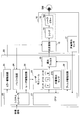
図3は、本実施の形態に係る制御装置について説明するブロック図の一例である。図3に示すように制御装置20において、レーザモジュール21は、電流値に応じた光量のレーザ光を出射するレーザ211R、211G、及び211Bや、レーザ211R、211G、及び211Bの夫々の直近の光量をモニタする光量検出センサ215等を備えている。
レーザ211Rは、例えば、赤色半導体レーザであり、波長λR(例えば、640nm)の光を出射することができる。レーザ211Gは、例えば、緑色半導体レーザであり、波長λG(例えば、530nm)の光を出射することができる。レーザ211Bは、例えば、青色半導体レーザであり、波長λB(例えば、445nm)の光を出射することができる。
光量検出センサ215としては、例えば、フォトダイオード等を用いることができる。光量検出センサ215は、減光手段である減光フィルタ22を透過前のレーザ光量を検出できる任意の位置に配置することができる。
レーザ211R、211G、及び211Bから出射された各波長のレーザ光は、ダイクロイックミラー等により合成され、減光フィルタ22に入射する。
減光フィルタ22は、減光比の異なる複数のフィルタを切り替え可能に構成されている。減光フィルタ22を構成する複数のフィルタの内の1つを選択することで、レーザ211R、211G、及び211Bから出射された光(合成後の光)を所定の減光比で減光することができる。但し、減光フィルタ22を構成する複数のフィルタには、入射光を略100%透過する仕様のものが含まれていてもよい。このように、減光フィルタ22は、表示装置1の使用者が視認する映像の輝度を調整する機能を有する。減光フィルタ22は、例えば、ND(Neutral Density)フィルタである。
減光フィルタ22は、例えば、図4に示す構成とすることができる。図4の例では、減光フィルタ22は、フィルタ221~227の7つのフィルタを備えており、フィルタ221~226にいくに従って減光比が低くなる(透過率が高くなる)ように設定されている。また、フィルタ227は透過率が略100%に設定されている。減光フィルタ22は、例えば、ステッピングモータにより矢印A方向に可動できるように構成されている。但し、フィルタの個数は7つに限定されず、要求仕様に応じて任意の個数とすることができる。
このように、減光フィルタ22は、減光比が最も高いフィルタ221と減光比が最も低いフィルタ227との間に、減光比が段階的に変化するように複数のフィルタ222~226を一列に配列した構造とすることができる。例えばステッピングモータ等を用いた機械的手段により、フィルタ221~227の内の1つのフィルタがレーザ光の光路上に選択的に配置されることで、レーザ光を所定の減光比で減光することができる。なお、減光比とは、各フィルタへ入射する光の光量と各フィルタから出射する光の光量との比率である。
図3に戻り、システムコントローラ23は、例えば、光走査部15のミラー(図示せず)の振れ角制御を行うことができる。システムコントローラ23は、例えば、光走査部15に設けられている水平変位センサ(図示せず)、垂直変位センサ(図示せず)で得られるミラーの水平方向及び垂直方向の傾きをバッファ回路24を介してモニタし、ミラー駆動回路25に角度制御信号を供給することができる。そして、ミラー駆動回路25は、システムコントローラ23からの角度制御信号に基づいて、光走査部15のミラーを所定角度に駆動(走査)することができる。
また、システムコントローラ23は、例えば、制御装置の外部から入力されるデジタルの映像信号に応じた駆動信号をレーザ駆動回路26に供給することができる。なお、制御装置の外部とは、例えば、パーソナルコンピュータやカメラモジュール等である。
レーザ駆動回路26は、システムコントローラ23からの駆動信号に基づいて、レーザモジュール21のレーザ211R、211G、及び211Bに所定の電流を供給する。これにより、レーザ211R、211G、及び211Bが映像信号に応じて変調された赤色、緑色、及び青色の光を発し、これらを合成することで、制御装置の外部から入力されるデジタルの映像信号に対応したカラーの映像を形成することができる。
制御手段であるCPU27には、装着部10の光量検出センサ17の出力(外光の光量)が、伝送ケーブル30を介して入力される。CPU27は、光量検出センサ17で検出した外光の光量に基づいて、レーザ211R、211G、及び211Bの夫々の電流値を増減すると共に減光フィルタ22を構成する複数のフィルタを切り替えて、使用者が視認する映像の輝度を制御する。
具体的には、CPU27は、装着部10の使用者の周囲の光量(外光の光量)を光量検出センサ17の出力によりモニタし、外光の光量に基づいて、レーザモジュール21に光量制御信号を供給し、レーザ211R、211G、及び211Bの夫々の電流値を増減する。
また、CPU27は、装着部10の使用者の周囲の光量(外光の光量)を光量検出センサ17の出力によりモニタし、外光の光量に基づいて、フィルタ駆動回路28に減光フィルタ22を切り替えるための切替信号を供給する。例えば、減光フィルタ22がステッピングモータにより可動できるように構成されている場合、フィルタ駆動回路28はステッピングモータに切替信号を供給して減光フィルタ22の所定のフィルタを選択することができる。
また、CPU27は、例えば、レーザ211R、211G、及び211Bの根元の出射光量を光量検出センサ215の出力によりモニタし、レーザモジュール21に光量制御信号を供給することができる。レーザ211R、211G、及び211Bは、CPU27からの光量制御信号に基づいて、所定の出力(光量)になるように電流制御される。ここで、所定の出力は、光量検出センサ17が検出した外光の光量に基づいて決定された目標光量であり、決定された目標光量からずれた分が光量検出センサ215の出力に基づいてフィードバック制御される。
なお、光量検出センサ215は、レーザ211R、211G、及び211Bの出射光量を独立に検出する3つのセンサを含む構成とすることができる。或いは、光量検出センサ215は、1つのセンサのみから構成してもよい。この場合には、レーザ211R、211G、及び211Bを順次発光させて、1つのセンサで順次検出することで、レーザ211R、211G、及び211Bの出射光量の制御が可能となる。
減光フィルタ22を構成する複数のフィルタの内の1つを透過したレーザ光は、伝送ケーブル30内の光ファイバ(図示せず)を介して、装着部10の光走査部15のミラーに照射され走査される。光走査部15のミラーに走査されたレーザ光は、投影光学系16により装着部10の使用者の網膜に直接投影されて映像が形成され、使用者は所定の輝度の映像を視認できる。
なお、図3において矢印の図示は省略されているが、CPU27は、システムコントローラ23、バッファ回路24、ミラー駆動回路25、及びレーザ駆動回路26とも接続され、これらの初期設定(出力する電圧値の範囲の設定等)を行う仕様となっている。
(レーザ光量と減光フィルタの制御)
図5は、レーザの入力電流と光出力(光量)との関係(所謂I-L特性)の一例を示す図である。レーザは、一定の電流(閾値電流)を印加したところからレーザ発光が始まる。そして、ある程度の電流を印加するまでは、電流に対する光出力の関係は非線形である。例えば、図5において、電流I1~電流I2までは、レーザの電流と光出力(光量)との関係が非線形の非線形領域である。
図5は、レーザの入力電流と光出力(光量)との関係(所謂I-L特性)の一例を示す図である。レーザは、一定の電流(閾値電流)を印加したところからレーザ発光が始まる。そして、ある程度の電流を印加するまでは、電流に対する光出力の関係は非線形である。例えば、図5において、電流I1~電流I2までは、レーザの電流と光出力(光量)との関係が非線形の非線形領域である。
非線形領域では、任意の輝度を出したつもりでも、実際には所望の輝度より弱かったり強かったりする。表示装置1は、R/G/Bの三色のレーザ光を合成することであらゆる色を表現するが、非線形領域を使用するとR/G/Bの出力のバランスが崩れ、期待の色が得られなくなる。従って、R/G/Bの各レーザにおいて、可能な限り非線形領域の使用を避ける必要がある。
なお、レーザに電流を流し過ぎると、光出力が飽和し、やはり非線形になる。電流を流し過ぎて非線形になった領域も使用には適さない。そのため、R/G/Bの各レーザに流す電流値にリミットを設けておき、常にレーザの電流と光出力(光量)との関係が線形の線形領域において、レーザの電流値を増減することが好ましい。
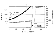
図6は、輝度の調整について説明する図であり、所望の輝度を得るためのディミングステップに対するレーザ光量と減光フィルタを構成する各フィルタとの関係の一例を示している。ここでは、減光フィルタは、図4に示した減光比の異なる7つのフィルタ221~227を備えているものとする。図6において、右上がりに傾斜する直線(連続する丸ドット)は、要求される映像の輝度を示し、各四角ドットは各フィルタを透過後のレーザ光量を示している。
図6の例では、フィルタ221~227が、ディミングステップ0(DS0)~ディミングステップ255(DS255)の256のディミングステップで輝度を切り替える仕様となっている。但し、これには限定されず、要求仕様に応じて、128、64、32等の任意のディミングステップで輝度を切り替える設計とすることができる。
図7は、図6のフィルタ221近傍の拡大図である。図7に示すように、最も減光比の高いフィルタ221を選択し、DS0でレーザ光量を36%とすることで、12cdの輝度を実現できる。DS1、DS2、・・・とディミングステップを上げるにしたがってレーザ光量が上がり、輝度が少しずつ高くなる。
フィルタ221で輝度が最大となるディミングステップまできたら、レーザ光量を下げた後、減光比の低いフィルタ222に切り替えることで、更に高い輝度を得ることができる。なお、図6及び図7の右側の軸のレーザ光量100%は、例えば、図5の電流I3に対応する光出力とすることができる。
図6を見ると、12cdの輝度を実現するために、フィルタ221より減光比が低いフィルタ222を選択し、レーザ光量を10%程度に絞ってもよいように思える。しかし、レーザ光量を低域するために入力電流を低くしていくとI-L特性の非線形領域(例えば、図5の電流I1~電流I2の領域)に至り、実際には所望の光量を得ることが難しくなる。従って、実際には、レーザ光量を25%程度までしか絞らない設計としている。
仮に、フィルタ222を選択してI-L特性の非線形領域を用いて輝度12cdでホワイトバランスを合わせたとしても、中間階調のホワイトバランス(灰色のバランス)が合っているとは限らず、例えば、映像が赤みがかって見えるなどしてしまう。一方、フィルタ221を選択して輝度12cdを実現する場合には、I-L特性の線形領域(例えば、図5の電流I2~電流I3の領域)を使用できるため、中間階調のホワイトバランスも仕様の範囲内に合わせることができる。
また、図6のフィルタ223とフィルタ224との間に梨地模様で示した部分があるが、これは、所望のディミングステップとするときに選択可能な減光フィルタが2通りあることを示している。
選択可能な減光フィルタが2通りあることは、フィルタ223とフィルタ224に限らず、減光比が隣接する他のフィルタについても同様である。つまり、複数のフィルタの内の一つのフィルタを選択しレーザに第1の電流値を設定した場合の映像の輝度と、一つのフィルタと減光比が隣接する他のフィルタを選択しレーザに第2の電流値を設定した場合の映像の輝度とが同一となる組み合わせが必ず存在する。
これは、周囲温度の変化やレーザの経年変化により、期待のレーザ光量と実際に得られたレーザ光量との間に差異がみられた場合に調整(LDAPC:LASER Diode Auto Power Control)を行う目的のために設けたオーバーラップである。
オーバーラップを認めない場合、レーザ光量の差異が存在した場合には減光フィルタの切替えが頻繁に行われる可能性がある。しかし、オーバーラップしていることで、減光フィルタはそのままとし、レーザ電流の切替えのみでレーザ光量の調整を行うことができる。オーバーラップ量は、例えば、各フィルタのディミングステップの20~30%程度とすることができる。
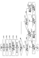
図8は、レーザ電流と減光フィルタ切り替えの制御のフローチャートの一例である。まず、ステップS101では、CPU27は、光量検出センサ17から外光光量を取得する。次に、ステップS102では、CPU27は、ステップS101で取得した外光光量に基づいて各レーザの目標光量を計算する。
次に、ステップS103では、CPU27は、光量検出センサ215から各レーザ(レーザ211R、211G、211B)の光量を取得する。次に、ステップS104では、CPU27は、ステップS103で取得した各レーザの光量と、ステップS102で計算した目標光量との差分を計算する。次に、ステップS105では、CPU27は、ステップS104で計算した差分から制御量(各レーザの電流値)を計算する。
次に、ステップS106では、CPU27は、ステップS103で取得した各レーザの光量よりも、ステップS102で計算した目標光量の方が大きいか否か判定する。ステップS106で目標光量の方が大きいと判定した場合(Yesの場合)にはステップS107に移行し、ステップS106で目標光量以下と判定した場合(Noの場合)にはステップS111に移行する。
次に、ステップS107では、CPU27は、減光フィルタの切替えを伴うか否かを判定する。ステップS107で減光フィルタの切替えを伴わないと判定した場合(Noの場合)にはステップS108に移行し、CPU27は、レーザモジュール21に光量制御信号を供給して各レーザの電流を増加する。
ステップS107で減光フィルタの切替えを伴うと判定した場合(Yesの場合)にはステップS109に移行し、CPU27は、レーザモジュール21に光量制御信号を供給して各レーザ電流を変更する。次に、ステップS110では、CPU27は、フィルタ駆動回路28に切替信号を供給して減光フィルタを透過率の低いものに切り替える。
なお、ステップS109において、『レーザ電流を変更する』としたのは、輝度を上げるために減光フィルタを透過率の低いものに切り替えた場合には、レーザ電流を増加する場合と減少する場合の両方があるためである。後述のステップS114についても同様である。
ステップS111では、CPU27は、減光フィルタの切替えを伴うか否かを判定する。ステップS111で減光フィルタの切替えを伴わないと判定した場合(Noの場合)にはステップS112に移行し、CPU27は、レーザモジュール21に光量制御信号を供給して各レーザの電流を減少する。
ステップS111で減光フィルタの切替えを伴うと判定した場合(Yesの場合)にはステップS113に移行し、CPU27は、フィルタ駆動回路28に切替信号を供給して減光フィルタを透過率の高いものに切り替える。次に、ステップS114では、CPU27は、レーザモジュール21に光量制御信号を供給して各レーザ電流を変更する。
なお、図8において、減光フィルタの切替えを伴うレーザ光量の切替えでは、次の点に注意が必要である。レーザ光量を上げる場合、例として、次の2パターンが考えられる。第1のパターンは、レーザ電流を増加させ、フィルタの透過率を上げる場合である。第2のパターンは、レーザ電流を減少させ、フィルタの透過率を上げる場合である(透過率を上げると明るくなりすぎるので、その分電流で微調整を行う場合を意味している)。
このうち、第2のパターンについては、フィルタの透過率を先に上げてしまうと、投影映像の光量は目標より高い状態になってしまう。これでは一時的に使用者に強い光量を照射することになり眩惑の危険性が発生するため、レーザ電流を先に変更するべきである。そのため、ステップS107~S110のような流れとしている。
レーザ光量を下げる場合、上記と同様に考えると、以下の2パターンが考えられる。第1のパターンは、レーザ電流を減少させ、減光フィルタの透過率を下げる場合である。第2のパターンは、レーザ電流を増加させ、減光フィルタの透過率を下げる場合である。
このうち、第2のパターンについては、先にレーザ電流を増加すると、一時的に目標光量より高い投影映像を使用者に照射することになるため、減光フィルタを先に切り替えるべきである。そのため、ステップS111~S114のような流れとしている。
ところで、人間は明るい環境から暗い環境へ(またはその逆)移動したときに、すぐには目が慣れない。一般的に、明順応は1分程度、暗順応は30分程度の時間を要する。これは、瞳孔の収縮・拡散にかかる時間ではなく、網膜の暗所視で必要な物質(ロドプシン)の分解及び合成によるものである。
そこで、表示装置1において、CPU27は、外光の光量の変化に対して、所定の遅延を持たせて映像の輝度を目標値に制御することが好ましい。具体的には、実際の目の慣れに合わせて(明順応(1分程度)及び暗順応(30分程度)に合わせて決定された)所定の遅延を持たせた光量の調整を行うと好適である。これにより、例えば、暗い環境下に移動した時に(屋外から屋内に移動した時等)、人間の目の慣れよりも早く映像が暗くなってしまう問題を避けることができる。
具体的には、図8のステップS102において、制御に使用する目標光量を、真の目標光量とは異なる値に設定し、徐々に真の目標光量に近づけるようにすればよい。すなわち、通常よりも時間をかけて真の目標光量に達するように制御すればよい。或いは、図8のステップS105において、制御量に1未満の任意の値を掛け合わせることにより、制御に遅延を持たせることも可能である。これらにより、使用者の眼の慣れに適応した輝度の制御が可能となる。
このように、本実施の形態に係る表示装置では、使用者の周囲の外光の光量を検出し、検出結果に基づいてレーザ電流及び減光フィルタの減光比を制御するので、使用者が明るい環境下で投影映像を暗く感じたり、逆に暗い環境下で投影映像を明るく感じたりするおそれを低減できる。すなわち、外光の明るさによらず、使用者にとって最適な明るさの映像を投影することが可能となる。
また、レーザ電流及び減光フィルタの減光比の制御は光量検出センサで得られた光量に基づいて自動で行うので、使用者が明るい環境から暗い環境(またはその逆)に移動したときに使用者に対し違和感を感じさせず投影映像の光量を制御することが可能となる。また、使用者に対しレーザ光で眩惑したり、逆に情報が見え難くなったりする問題を解消することが可能となる。
また、外光と同じ光量の投影映像とすることができるので、外部環境または投影映像の片方が見づらくなったり、投影映像により幻惑されたりすることがなくなる。従って、外部環境に投影映像をオーバーラップさせるようなアプリケーションでも使用者は違和感なく使用することができる。
また、輝度の制御は、レーザ電流の増減と、減光フィルタの減光比の切り替えとの両方により行うので、減光フィルタの段数(フィルタ数)を抑えることができる。また、レーザの電流制御のみで行うことにより生ずる低階調領域のホワイトバランスのずれを低減することが可能となる。
また、レーザは閾値電流付近の低階調領域では、一般に電流に対する光出力は非線形である。よって、低階調ではR/G/B各色が期待の光量とならないことで、期待の色が出ないおそれがある。表示装置1では、外光に対するレーザ電流の制御に減光フィルタの切り替え制御を組み合わせているため、レーザの線形領域を容易に使用することが可能となり、期待の色を出力することができる。
また、人間の目の暗順応及び明順応に合わせて、輝度の制御に遅延を持たせることにより、人間の目の「慣れ」に応じた自然な輝度の変化を実現できる。
以上、好ましい実施の形態について詳説したが、上述した実施の形態に制限されることはなく、特許請求の範囲に記載された範囲を逸脱することなく、上述した実施の形態に種々の変形及び置換を加えることができる。
例えば、上記の実施の形態では、映像を左眼のみに投影する表示装置の例を示したが、映像を左眼及び右眼に投影する表示装置とすることも可能である。この場合には、左右のテンプル10tそれぞれに光走査部15並びにレンズ161及びハーフミラー162を実装すると共に左右に1つずつ光量検出センサ17を配置し、それぞれの眼に投影する映像の輝度を制御する制御装置20を設ければよい。これにより、左右独立にレーザ電流及び減光フィルタを制御可能となり、両眼に対し適切な光量の映像を投影することができる。
例えば、片目で拡大鏡を覗くような、左右の眼で見ているものが異なる場合に対して有効である。
例えば、片目で拡大鏡を覗くような、左右の眼で見ているものが異なる場合に対して有効である。
また、上記の実施の形態では、レーザ電流及び減光フィルタの減光比の制御を光量検出センサで得られた光量に基づいて自動で行う例を示したが、レーザ電流及び減光フィルタの減光比の制御を使用者がマニュアルで行う構成とすることもできる。例えば、制御ボックスに設けたスイッチを使用者が押すたびに使用者の眼に投影される映像の輝度が変わるように構成することができる。これにより、使用者の意志により最適な光量を投影することが可能となる。
また、上記の実施の形態では、装着部を眼鏡型としたが、装着部は必ずしも眼鏡型としなくてもよい。例えば、投影光学系を内蔵した装着部を、装着者が頭部に装着する一般的な眼鏡に着脱可能な形状としてもよい。この場合、眼鏡の右眼側と左眼側の何れの側にも着脱可能に構成することで、様々なユーザが利き眼に合わせて利用できる。
また、上記の実施の形態では、減光フィルタは減光比の異なる複数のフィルタを一列に配列してフィルタを切り替える構造とする例を示したが、複数のフィルタが重なるように配列して、フィルタを重ねる枚数を変化させて減光比を切り替える構造としてもよい。この場合、フィルタはすべて同じの減光比を持つものを使用するようにしてもよい。
また、上記の実施の形態に係る表示装置は、網膜走査型のヘッドマウントディスプレイのみならず、各種ウェアラブル端末に適用できる。
本国際出願は2016年4月22日に出願した日本国特許出願2016-085904号に基づく優先権を主張するものであり、日本国特許出願2016-085904号の全内容を本国際出願に援用する。
1 表示装置
10 装着部
10f フロント
10t テンプル
15 光走査部
16 投影光学系
17、215 光量検出センサ
20 制御装置
20B 制御ボックス
21 レーザモジュール
22 減光フィルタ
23 システムコントローラ
24 バッファ回路
25 ミラー駆動回路
26 レーザ駆動回路
27 CPU
28 フィルタ駆動回路
30 伝送ケーブル
161 レンズ
162 ハーフミラー
211R、211G、211B レーザ
221、222、223、224、225、226、227 フィルタ
500 眼球
10 装着部
10f フロント
10t テンプル
15 光走査部
16 投影光学系
17、215 光量検出センサ
20 制御装置
20B 制御ボックス
21 レーザモジュール
22 減光フィルタ
23 システムコントローラ
24 バッファ回路
25 ミラー駆動回路
26 レーザ駆動回路
27 CPU
28 フィルタ駆動回路
30 伝送ケーブル
161 レンズ
162 ハーフミラー
211R、211G、211B レーザ
221、222、223、224、225、226、227 フィルタ
500 眼球
Claims (10)
- 使用者の頭部に装着し、前記使用者に所定の映像を視認させる表示装置であって、
外光の光量を検出する光量検出手段と、
電流値に応じた光量のレーザ光を出射するレーザと、
減光比を切り替え可能なフィルタを備え、前記レーザ光を減光する減光手段と、
前記フィルタを透過した前記レーザ光を走査する光走査部と、
走査された前記レーザ光を投影して映像を形成する投影光学系と、
前記光量検出手段で検出した前記外光の光量に基づいて、前記電流値を増減すると共に前記フィルタの減光比を切り替えて前記映像の輝度を制御する制御手段と、を有することを特徴とする表示装置。 - 前記制御手段は、前記外光の光量の変化に対して、所定の遅延を持たせて前記映像の輝度を目標値に制御することを特徴とする請求項1に記載の表示装置。
- 前記所定の遅延は、人間の目の暗順応及び明順応に合わせて決定されることを特徴とする請求項2に記載の表示装置。
- 前記制御手段は、前記映像の輝度を上げる場合であって、前記電流値を減少させ、前記フィルタの減光比を高いものから低いものに切り替える場合には、前記電流値を変更し、その後前記フィルタを切り替えることを特徴とする請求項1に記載の表示装置。
- 前記制御手段は、前記映像の輝度を下げる場合であって、前記電流値を増加させ、前記フィルタの減光比を低いものから高いものに切り替える場合には、前記フィルタを切り替え、その後前記電流値を変更することを特徴とする請求項1に記載の表示装置。
- 前記フィルタの内の一つの減光比となるフィルタを選択し前記レーザに第1の電流値を設定した場合の前記映像の輝度と、前記一つの減光比となるフィルタと減光比が隣接する他の減光比となるフィルタを選択し前記レーザに第2の電流値を設定した場合の前記映像の輝度と、が同一となる組み合わせが存在することを特徴とする請求項1に記載の表示装置。
- 前記制御手段は、前記レーザの電流と光量との関係が線形の領域において、前記電流値を増減することを特徴とする請求項1に記載の表示装置。
- 前記減光手段は、減光比の異なる複数のフィルタを備え、
減光比が最も高いフィルタと減光比が最も低いフィルタとの間に、減光比が段階的に変化するように複数のフィルタを一列に配列した構造であり、機械的手段により1つのフィルタが前記レーザ光の光路上に選択的に配置されることを特徴とする請求項1に記載の表示装置。 - 前記投影光学系は、前記使用者の眼の網膜に前記映像を投影することを特徴とする請求項1に記載の表示装置。
- 前記使用者の頭部に装着可能な眼鏡型の装着部と、前記装着部を制御する制御装置と、前記装着部と前記制御装置とを接続する伝送ケーブルと、を備え、
前記光量検出手段、前記光走査部、及び前記投影光学系は、前記装着部に配置され、
前記レーザ、前記減光手段、及び前記制御手段は、前記制御装置に配置され、
前記レーザ光は、前記伝送ケーブルを介して伝送されることを特徴とする請求項1に記載の表示装置。
Priority Applications (1)
| Application Number | Priority Date | Filing Date | Title |
|---|---|---|---|
| US16/092,251 US10699672B2 (en) | 2016-04-22 | 2017-04-04 | Display device |
Applications Claiming Priority (2)
| Application Number | Priority Date | Filing Date | Title |
|---|---|---|---|
| JP2016085904A JP6836050B2 (ja) | 2016-04-22 | 2016-04-22 | 表示装置 |
| JP2016-085904 | 2016-04-22 |
Publications (1)
| Publication Number | Publication Date |
|---|---|
| WO2017183446A1 true WO2017183446A1 (ja) | 2017-10-26 |
Family
ID=60116725
Family Applications (1)
| Application Number | Title | Priority Date | Filing Date |
|---|---|---|---|
| PCT/JP2017/014137 Ceased WO2017183446A1 (ja) | 2016-04-22 | 2017-04-04 | 表示装置 |
Country Status (3)
| Country | Link |
|---|---|
| US (1) | US10699672B2 (ja) |
| JP (1) | JP6836050B2 (ja) |
| WO (1) | WO2017183446A1 (ja) |
Families Citing this family (7)
| Publication number | Priority date | Publication date | Assignee | Title |
|---|---|---|---|---|
| JP2019056745A (ja) * | 2017-09-20 | 2019-04-11 | セイコーエプソン株式会社 | ヘッドマウントディスプレイ及び画像表示装置 |
| JP2019159100A (ja) | 2018-03-13 | 2019-09-19 | 株式会社リコー | 光走査装置、画像表示装置、ヘッドアップディスプレイ、及び移動体 |
| JP7208463B2 (ja) | 2018-05-15 | 2023-01-19 | ミツミ電機株式会社 | 制御装置、光走査装置、表示装置及び制御方法 |
| JP2020004802A (ja) * | 2018-06-26 | 2020-01-09 | 株式会社Qdレーザ | レーザドライバ、光源および画像投影装置 |
| US12044854B2 (en) * | 2019-09-09 | 2024-07-23 | Google Llc | Method and system for projecting an image within an eye safety limit |
| DE102020205937A1 (de) | 2020-05-12 | 2021-11-18 | Robert Bosch Gesellschaft mit beschränkter Haftung | Brillenvorrichtung und Verfahren zum Einstellen einer Helligkeit des zumindest einen Bilds |
| DE102023206113A1 (de) * | 2023-06-28 | 2025-01-02 | Robert Bosch Gesellschaft mit beschränkter Haftung | Optisches System für eine virtuelle Netzhautanzeige |
Citations (8)
| Publication number | Priority date | Publication date | Assignee | Title |
|---|---|---|---|---|
| JPH11109882A (ja) * | 1997-10-06 | 1999-04-23 | Minolta Co Ltd | 映像表示装置 |
| JP2005107125A (ja) * | 2003-09-30 | 2005-04-21 | Brother Ind Ltd | 網膜走査表示装置 |
| JP2007101618A (ja) * | 2005-09-30 | 2007-04-19 | Konica Minolta Photo Imaging Inc | 表示装置 |
| JP2009086365A (ja) * | 2007-09-28 | 2009-04-23 | Brother Ind Ltd | 画像表示装置 |
| US20120105310A1 (en) * | 2010-11-03 | 2012-05-03 | Trex Enterprises Corporation | Dynamic foveal vision display |
| JP2012212023A (ja) * | 2011-03-31 | 2012-11-01 | Brother Ind Ltd | ヘッドマウントディスプレイ,及びその輝度調整方法 |
| JP2014195184A (ja) * | 2013-03-29 | 2014-10-09 | Funai Electric Co Ltd | プロジェクタおよびヘッドアップディスプレイ装置 |
| JP2015049266A (ja) * | 2013-08-30 | 2015-03-16 | 株式会社リコー | 画像形成装置、車両、及び画像形成装置の制御方法 |
Family Cites Families (9)
| Publication number | Priority date | Publication date | Assignee | Title |
|---|---|---|---|---|
| JPH05300451A (ja) * | 1992-04-22 | 1993-11-12 | Olympus Optical Co Ltd | 頭部装着式ディスプレイ装置 |
| JP2001007023A (ja) * | 2000-01-01 | 2001-01-12 | Nikon Corp | 投影露光方法及び装置、並びに素子製造方法 |
| JP2004226870A (ja) * | 2003-01-27 | 2004-08-12 | Mitsubishi Electric Corp | 表示装置 |
| JP4802806B2 (ja) | 2006-03-28 | 2011-10-26 | ブラザー工業株式会社 | 画像表示装置 |
| JP2012110485A (ja) * | 2010-11-24 | 2012-06-14 | Fujifilm Corp | 光源装置および内視鏡装置 |
| JP6044188B2 (ja) * | 2012-08-30 | 2016-12-14 | 日本精機株式会社 | 表示装置 |
| KR20150043934A (ko) * | 2013-10-15 | 2015-04-23 | 삼성전자주식회사 | 디스플레이의 밝기를 제어하는 방법 및 장치 |
| US9143720B2 (en) * | 2013-10-31 | 2015-09-22 | Htc Corporation | Handheld electronic device and image projection method of the same |
| CN106255917B (zh) * | 2014-04-30 | 2018-12-07 | 夏普株式会社 | 反射投影型显示装置 |
-
2016
- 2016-04-22 JP JP2016085904A patent/JP6836050B2/ja active Active
-
2017
- 2017-04-04 US US16/092,251 patent/US10699672B2/en active Active
- 2017-04-04 WO PCT/JP2017/014137 patent/WO2017183446A1/ja not_active Ceased
Patent Citations (8)
| Publication number | Priority date | Publication date | Assignee | Title |
|---|---|---|---|---|
| JPH11109882A (ja) * | 1997-10-06 | 1999-04-23 | Minolta Co Ltd | 映像表示装置 |
| JP2005107125A (ja) * | 2003-09-30 | 2005-04-21 | Brother Ind Ltd | 網膜走査表示装置 |
| JP2007101618A (ja) * | 2005-09-30 | 2007-04-19 | Konica Minolta Photo Imaging Inc | 表示装置 |
| JP2009086365A (ja) * | 2007-09-28 | 2009-04-23 | Brother Ind Ltd | 画像表示装置 |
| US20120105310A1 (en) * | 2010-11-03 | 2012-05-03 | Trex Enterprises Corporation | Dynamic foveal vision display |
| JP2012212023A (ja) * | 2011-03-31 | 2012-11-01 | Brother Ind Ltd | ヘッドマウントディスプレイ,及びその輝度調整方法 |
| JP2014195184A (ja) * | 2013-03-29 | 2014-10-09 | Funai Electric Co Ltd | プロジェクタおよびヘッドアップディスプレイ装置 |
| JP2015049266A (ja) * | 2013-08-30 | 2015-03-16 | 株式会社リコー | 画像形成装置、車両、及び画像形成装置の制御方法 |
Also Published As
| Publication number | Publication date |
|---|---|
| US20190122635A1 (en) | 2019-04-25 |
| US10699672B2 (en) | 2020-06-30 |
| JP6836050B2 (ja) | 2021-02-24 |
| JP2017194623A (ja) | 2017-10-26 |
Similar Documents
| Publication | Publication Date | Title |
|---|---|---|
| JP6836050B2 (ja) | 表示装置 | |
| US8159417B2 (en) | Image display device | |
| EP2112832B1 (en) | Image display device | |
| CN104812342B (zh) | 视觉帮助投影仪 | |
| US10495888B2 (en) | Image display device capable of adjusting image position in depth direction | |
| TW201732369A (zh) | 用於擴增近眼可穿戴顯示器之系統及方法 | |
| US20120188623A1 (en) | Scanning image display device and method of controlling the same | |
| JP6853477B2 (ja) | 表示装置 | |
| JP2012511181A (ja) | 投射型画像表示装置のための制御可能な光アレイ | |
| KR20200092424A (ko) | 눈 투영 시스템 | |
| JP6784058B2 (ja) | 情報表示装置 | |
| WO2014162414A1 (ja) | 投影装置、ヘッドアップディスプレイ、制御方法、プログラム及び記憶媒体 | |
| JP5163535B2 (ja) | ヘッドマウントディスプレイ | |
| JP2012078532A (ja) | 画像表示装置 | |
| WO2020100484A1 (ja) | ヘッドマウントディスプレイ、及び表示方法 | |
| CN121925585A (zh) | 用于校准具有虚拟视网膜显示器的数据眼镜的方法、计算单元和数据眼镜 | |
| JP7245376B2 (ja) | 電子機器および表示方法 | |
| JP7133163B2 (ja) | 網膜走査型画像投影装置、網膜走査型画像投影方法、網膜走査型画像投影システム | |
| JP2017079132A (ja) | 光出力制御ユニット、及び光投射装置 | |
| WO2019098265A1 (ja) | 色覚支援装置 | |
| WO2022239323A1 (ja) | 光源装置及び画像表示装置 | |
| WO2022176311A1 (ja) | ヘッドマウントディスプレイ装置およびその制御方法 | |
| JP2017156547A (ja) | 画像表示装置、制御方法、プログラム及び記憶媒体 | |
| KR20220149787A (ko) | 증강 현실 안경용 투영 장치, 투영 장치를 이용한 이미지 정보 표시 방법 및 제어 장치 |
Legal Events
| Date | Code | Title | Description |
|---|---|---|---|
| NENP | Non-entry into the national phase |
Ref country code: DE |
|
| 121 | Ep: the epo has been informed by wipo that ep was designated in this application |
Ref document number: 17785788 Country of ref document: EP Kind code of ref document: A1 |
|
| 122 | Ep: pct application non-entry in european phase |
Ref document number: 17785788 Country of ref document: EP Kind code of ref document: A1 |