WO2017183234A1 - ヒートポンプ装置のファン駆動回路 - Google Patents
ヒートポンプ装置のファン駆動回路 Download PDFInfo
- Publication number
- WO2017183234A1 WO2017183234A1 PCT/JP2016/088355 JP2016088355W WO2017183234A1 WO 2017183234 A1 WO2017183234 A1 WO 2017183234A1 JP 2016088355 W JP2016088355 W JP 2016088355W WO 2017183234 A1 WO2017183234 A1 WO 2017183234A1
- Authority
- WO
- WIPO (PCT)
- Prior art keywords
- refrigerant
- heat pump
- drive circuit
- pump device
- fan
- Prior art date
- Legal status (The legal status is an assumption and is not a legal conclusion. Google has not performed a legal analysis and makes no representation as to the accuracy of the status listed.)
- Ceased
Links
Images




Classifications
-
- F—MECHANICAL ENGINEERING; LIGHTING; HEATING; WEAPONS; BLASTING
- F24—HEATING; RANGES; VENTILATING
- F24F—AIR-CONDITIONING; AIR-HUMIDIFICATION; VENTILATION; USE OF AIR CURRENTS FOR SCREENING
- F24F11/00—Control or safety arrangements
- F24F11/70—Control systems characterised by their outputs; Constructional details thereof
- F24F11/72—Control systems characterised by their outputs; Constructional details thereof for controlling the supply of treated air, e.g. its pressure
- F24F11/74—Control systems characterised by their outputs; Constructional details thereof for controlling the supply of treated air, e.g. its pressure for controlling air flow rate or air velocity
-
- F—MECHANICAL ENGINEERING; LIGHTING; HEATING; WEAPONS; BLASTING
- F24—HEATING; RANGES; VENTILATING
- F24F—AIR-CONDITIONING; AIR-HUMIDIFICATION; VENTILATION; USE OF AIR CURRENTS FOR SCREENING
- F24F11/00—Control or safety arrangements
- F24F11/30—Control or safety arrangements for purposes related to the operation of the system, e.g. for safety or monitoring
- F24F11/32—Responding to malfunctions or emergencies
- F24F11/36—Responding to malfunctions or emergencies to leakage of heat-exchange fluid
-
- F—MECHANICAL ENGINEERING; LIGHTING; HEATING; WEAPONS; BLASTING
- F24—HEATING; RANGES; VENTILATING
- F24F—AIR-CONDITIONING; AIR-HUMIDIFICATION; VENTILATION; USE OF AIR CURRENTS FOR SCREENING
- F24F11/00—Control or safety arrangements
- F24F11/30—Control or safety arrangements for purposes related to the operation of the system, e.g. for safety or monitoring
- F24F11/32—Responding to malfunctions or emergencies
- F24F11/38—Failure diagnosis
-
- F—MECHANICAL ENGINEERING; LIGHTING; HEATING; WEAPONS; BLASTING
- F24—HEATING; RANGES; VENTILATING
- F24F—AIR-CONDITIONING; AIR-HUMIDIFICATION; VENTILATION; USE OF AIR CURRENTS FOR SCREENING
- F24F11/00—Control or safety arrangements
- F24F11/88—Electrical aspects, e.g. circuits
-
- F—MECHANICAL ENGINEERING; LIGHTING; HEATING; WEAPONS; BLASTING
- F25—REFRIGERATION OR COOLING; COMBINED HEATING AND REFRIGERATION SYSTEMS; HEAT PUMP SYSTEMS; MANUFACTURE OR STORAGE OF ICE; LIQUEFACTION SOLIDIFICATION OF GASES
- F25B—REFRIGERATION MACHINES, PLANTS OR SYSTEMS; COMBINED HEATING AND REFRIGERATION SYSTEMS; HEAT PUMP SYSTEMS
- F25B1/00—Compression machines, plants or systems with non-reversible cycle
-
- F—MECHANICAL ENGINEERING; LIGHTING; HEATING; WEAPONS; BLASTING
- F25—REFRIGERATION OR COOLING; COMBINED HEATING AND REFRIGERATION SYSTEMS; HEAT PUMP SYSTEMS; MANUFACTURE OR STORAGE OF ICE; LIQUEFACTION SOLIDIFICATION OF GASES
- F25B—REFRIGERATION MACHINES, PLANTS OR SYSTEMS; COMBINED HEATING AND REFRIGERATION SYSTEMS; HEAT PUMP SYSTEMS
- F25B49/00—Arrangement or mounting of control or safety devices
- F25B49/02—Arrangement or mounting of control or safety devices for compression type machines, plants or systems
Definitions
- the present invention relates to a fan drive circuit of a heat pump device.
- R32 refrigerants having a low global warming potential have been increasingly used in air conditioners that cool and heat indoors using a vapor compression refrigeration cycle.
- the R32 refrigerant has a slight flammability (slightly flammability).
- the leaked refrigerant accumulates near the floor surface. May reach flammable concentration.
- protection device In order to prevent leakage refrigerant from staying and reaching the flammable concentration, various protection devices or protection mechanisms (hereinafter, represented by “protection device”) are conceivable.
- a refrigerant sensor as a protective device is arranged in the indoor unit to determine whether there is leakage from the refrigerant circuit, and when this refrigerant sensor detects refrigerant leakage, the indoor fan provided in the indoor unit is driven. It has been proposed to diffuse the leaked refrigerant (see, for example, Patent Documents 1 and 2). According to the indoor units described in Patent Documents 1 and 2, it is possible to prevent the refrigerant from reaching the flammable concentration by diffusing the leaked refrigerant by blowing air, and to ensure safety for indoor residents when the refrigerant leaks Can do.
- a protective device other than the refrigerant sensor an alarm device that informs the user of refrigerant leakage by sound or light, a ventilation device that forcibly exhausts indoor air containing the refrigerant to the outside, and the like are conceivable.
- connection in this specification includes not only a state in which the indoor unit and the protection device are connected by wire, but also a state in which they can communicate with each other wirelessly.
- the present invention has been made in view of such circumstances, and when the connection between the protection device and the heat pump device such as the indoor unit is disconnected, even if the refrigerant leaks, the leaked refrigerant has a combustible concentration. It is an object of the present invention to provide a fan drive circuit for a heat pump device that can prevent the temperature from reaching.
- the fan drive circuit of the heat pump device of the present invention (hereinafter also simply referred to as “fan drive circuit”) (1)
- a forcible operation circuit for operating the fan in response to an event that a protection device that prevents leakage refrigerant from the heat pump device from reaching a flammable concentration cannot be detected is connected to the heat pump device.
- the fan drive circuit of the present invention includes a forced operation circuit, and the forced operation circuit detects that a protective device that prevents leakage refrigerant from the heat pump device from reaching a flammable concentration is connected to the heat pump device.
- the fan is driven by an event that it cannot be done. That is, when the protection device such as the refrigerant sensor is disconnected from the heat pump device and the protection function of the protection device cannot be exhibited, the fan is forcibly operated in a fail-safe manner. As a result, even if the refrigerant leaks while the connection between the protective device and the heat pump device is disconnected, the leaked refrigerant is diffused by forced operation of the fan, and the leaked refrigerant stays on the floor surface of the air conditioning room.
- the “heat pump device” in this specification refers to a device that transfers heat using a refrigerant and a heat exchanger, and includes not only the above-described indoor unit of an air conditioner but also the outdoor unit of the air conditioner. It is a concept that includes a hot water supply device that performs hot water supply and hot water supply.
- the forced operation circuit can be a closed circuit on the power supply side with respect to the operation switch of the heat pump device.
- the protection device and the heat pump device can be operated by operating the fan due to an event that the protection device cannot be connected to the heat pump device. Even if the refrigerant leaks with the connection to the fan disconnected, the leaked refrigerant is diffused by forced operation of the fan, and it is always prevented that the leaked refrigerant stays on the floor surface of the air conditioning room and reaches the flammable concentration can do.
- the fan drive circuit according to (1) or (2) may include a relay that opens the forced operation circuit when the protection device is connected to a heat pump device. In this case, in a normal state where the protection device is connected to the heat pump device, the forced drive circuit can be controlled to open and close.
- the protection device is a refrigerant sensor that detects leakage of refrigerant from the heat exchanger or refrigerant piping connected to the heat exchanger. Can do. In this case, if the connection between the refrigerant sensor and the heat pump device is disconnected and the function of the refrigerant sensor cannot be performed, the fan is forcibly operated in a fail-safe manner. By diffusing the leaked refrigerant, it is possible to prevent the leaked refrigerant from staying on the floor surface of the air-conditioning room and reaching the flammable concentration.
- the leaked refrigerant when the connection between the protection device and the heat pump device is disconnected, the leaked refrigerant can be prevented from reaching the flammable concentration even if the refrigerant leaks.
- FIG. 3 is an explanatory diagram of an embodiment of the fan drive circuit of the present invention (when the indoor unit is stopped, the sensor is not connected). It is explanatory drawing (one sensor undetected during indoor unit operation) of one Embodiment of the fan drive circuit of this invention. It is explanatory drawing (sensor detection during indoor unit driving
- FIG. 1 is an explanatory diagram of a fan drive circuit 1 according to an embodiment of the present invention, and is a fan drive circuit in a state before power is supplied to an indoor unit as a heat pump device and a refrigerant sensor 2 as a protection device. 1 is shown.
- 2 to 4 are explanatory diagrams of the fan drive circuit 1 in which the indoor unit and the refrigerant sensor 2 are powered on, but the operation of the indoor unit is stopped.
- 5 to 7 are explanatory diagrams of the fan drive circuit 1 in which separate power is supplied to the indoor unit and the refrigerant sensor 2 and the indoor unit is in operation.
- the fan drive circuit 1 is a circuit that drives an indoor fan provided in the indoor unit in an air conditioner or air conditioner including an indoor unit and an outdoor unit.
- the indoor unit includes a heat exchanger and the like, and conditioned air heat-exchanged by the heat exchanger is blown out from the outlet by the indoor fan.
- the heat exchanger performs heat exchange with air sucked into the apparatus by an indoor fan using, for example, R32 refrigerant, which is a slightly flammable or flammable refrigerant having a specific gravity greater than that of air. *
- the fan drive circuit of the present invention a slightly flammable or combustible refrigerant leaks from a heat exchanger or a refrigerant pipe connected to the heat exchanger, and the leaked refrigerant is in a room where an indoor unit is installed. It is a circuit that prevents it from staying on the floor of an air conditioning room and reaching a flammable concentration. Therefore, the fan drive circuit of the present invention can be suitably applied to floor-standing indoor units that are considered to have a relatively high possibility that the leaked refrigerant will stay on the floor surface.
- the present invention is not limited, and the present invention can be applied to other indoor units such as a ceiling-mounted indoor unit and a wall-mounted indoor unit, and also to other heat pump devices such as an outdoor unit and a water heater. Further, the present invention can be applied not only to an indoor unit that air-conditions a room where people stay, but also to an indoor unit that air-conditions a space in which machines and devices are mainly arranged, such as a server room and a clean room.
- the fan drive circuit 1 and the refrigerant sensor 2 are connected to be communicable with each other by wire or wirelessly.
- wireless communication for example, communication can be performed using infrared rays.
- the refrigerant sensor 2 can be provided in the indoor unit, for example, below the heat exchanger or below the connection portion between the heat exchanger and the refrigerant pipe, but it is assumed that the refrigerant stays when the refrigerant leaks. It can also be provided at an appropriate location in the air-conditioned room. In the latter case, the refrigerant sensor 1 and the indoor unit are normally connected so as to be able to communicate with each other wirelessly.
- the contact 2a of the refrigerant sensor 2 is opened, and the circuit including the refrigerant sensor 2 is opened (see FIG. 3).
- the fan drive circuit 1 includes a forced operation circuit that operates the fan motor 3 of the indoor fan when the refrigerant sensor 2 cannot be detected to be connected to the indoor unit.
- the forced operation circuit can be a closed circuit on the power supply side with respect to the operation switch 4 of the indoor unit.
- the forced operation circuit can be a closed circuit including the refrigerant sensor 2, the fan motor 3, and the first relay 5 on the power supply side with respect to the operation switch 4.
- the first relay 5 operates in conjunction with the refrigerant sensor 2.
- the 1st relay 5 is provided with b contact 5a which constitutes a closed circuit including fan motor 3 on the power source side from operation switch 4 of an indoor unit.
- the fan drive circuit 1 includes a second relay 6.
- the second relay 6 is a relay on the control side of the indoor unit, and includes an a contact 6a that is “closed” when energized.
- the operation switch 4 of the indoor unit that is, the air conditioner is turned on by the operation of the remote controller or the like
- the contact 7 is closed by an instruction of a control unit such as a microcomputer in the air conditioner, thereby energizing the second relay 6. Is done.
- the second relay 6 is energized, the contact a 6a of the second relay 6 is closed, and the fan motor 3 is driven according to the normal control of the indoor unit (see FIG. 5).
- FIG. 2 shows a state where the indoor unit and the refrigerant sensor 2 are powered on, but the operation of the indoor unit is stopped and the refrigerant sensor 2 is not detecting the refrigerant.
- the contact 2a of the refrigerant sensor 2 is opened as described above, and the first relay 5 is not energized. It becomes a state.
- the first relay 5 is in a non-energized state, the b contact 5a of the first relay 5 is closed, and the indoor unit is stopped from normal operation under microcomputer control, but the fan motor 3 is driven to drive the indoor fan. Is forced to run.
- the indoor fan is forcibly operated when the refrigerant sensor 2 detects the leaked refrigerant, so that the leaked refrigerant can be diffused and the leaked refrigerant is stored on the floor surface of the air conditioning room. It is possible to prevent the flammable concentration from staying.
- the connection is detected.
- the indoor fan can be forcibly operated even when the refrigerant sensor 2 cannot exhibit the leakage refrigerant detection function.
- the first relay 5 when the refrigerant sensor 2 is removed from the indoor unit, the first relay 5 is in a non-energized state.
- the b contact 5a of the first relay 5 is closed and the indoor unit is stopped, but the fan motor 3 is driven to forcibly operate the indoor fan.
- the fan drive circuit according to the present embodiment is configured to work on the safe side by fail-safe even when the operation of the indoor unit is stopped. As a result, even if the refrigerant leaks in a state where the refrigerant sensor 2 and the indoor unit are disconnected, the leaked refrigerant stays on the floor surface of the air-conditioning room and the like by forcibly operating the indoor fan. Can be prevented. As a result, it is possible to ensure the safety of indoor occupants and the machines and devices disposed in the room when the refrigerant leaks.
- FIG. 5 shows the fan drive circuit 1 in a state where the indoor unit is in operation and the refrigerant sensor 2 is not detecting the refrigerant.
- the operation switch 4 of the indoor unit that is, the air conditioner is turned on by the operation of the remote controller or the like
- the contact 7 is closed by an instruction from a control unit such as a microcomputer in the air conditioner.
- 2 relay 6 is energized.
- the second relay 6 is energized, the contact a of the second relay 6 is closed, the fan motor 3 is driven according to the normal control of the indoor unit, and the compressor in the outdoor unit can be operated. Become.
- the indoor unit is operated in the “low wind speed” state by the operation mode by the normal control
- the indoor fan is forcibly operated in the “high wind speed” state, for example. Therefore, the leaked refrigerant can be diffused, and the leaked refrigerant can be prevented from staying on the floor surface of the air-conditioning room and reaching the flammable concentration.
- the indoor fan can be forcibly operated.
- the first relay 5 enters a non-energized state.
- the b contact 5a of the first relay 5 is closed, and the indoor fan is switched from the operation mode by normal control (FIG. 5) to the forced operation mode to be forcibly operated.
- the contact 7 is in an “open” state, and the compressor cannot be operated.
- the fan drive circuit 1 is configured to work on the safe side by fail-safe. As a result, even if the refrigerant leaks in a state where the refrigerant sensor 2 and the indoor unit are disconnected, the leaked refrigerant stays on the floor surface of the air-conditioning room and the like by forcibly operating the indoor fan. Can be prevented. As a result, it is possible to ensure the safety of indoor occupants and the machines and devices disposed in the room when the refrigerant leaks.
- the fan drive circuit 1 can normally operate the air conditioner if the refrigerant sensor 2 as a protection device is connected to the indoor unit, but if the refrigerant sensor 2 is not connected to the indoor unit. It is comprised so that an air conditioner cannot be normally operated.
- the indoor fan is operated under normal control when the refrigerant sensor 2 does not detect the leaked refrigerant, but the indoor fan is configured to be forcibly operated when the refrigerant sensor 2 detects the leaked refrigerant. Thereby, it is possible to prevent the leaked refrigerant from reaching the combustible concentration.
- a refrigerant sensor is used as the protection device, and when the refrigerant leaked from the indoor unit is detected by the refrigerant sensor, the indoor fan is forcibly operated to diffuse the leaked refrigerant.
- an alarm device that informs the user of a refrigerant leak by sound or light when detecting a leaked refrigerant, or a ventilator that forcibly discharges indoor air containing the leaked refrigerant to the outside.
- coolant sensor, an alarm device, and a ventilation apparatus can also be used independently, and can also be used in combination of 2 or more.
- the fan drive circuit of the present invention includes a forced operation circuit that operates the fan of the heat pump device in a fail-safe manner when the alarm device or the ventilation device is disconnected from the heat pump device.
Landscapes
- Engineering & Computer Science (AREA)
- Mechanical Engineering (AREA)
- General Engineering & Computer Science (AREA)
- Chemical & Material Sciences (AREA)
- Combustion & Propulsion (AREA)
- Physics & Mathematics (AREA)
- Thermal Sciences (AREA)
- Fluid Mechanics (AREA)
- Health & Medical Sciences (AREA)
- Biomedical Technology (AREA)
- Air Conditioning Control Device (AREA)
Abstract
空気よりも比重の大きな微燃性ないしは可燃性冷媒を使用する熱交換器により熱交換された空気をファンにより吹出口から吹き出すヒートポンプ装置のファン駆動回路1。前記ヒートポンプ装置からの漏洩冷媒が可燃濃度に達するのを防止する保護装置が当該ヒートポンプ装置に接続されているのを検知することができないという事象により前記ファンを運転させる強制運転回路を備えている。
Description
本発明はヒートポンプ装置のファン駆動回路に関する。
近年、蒸気圧縮式の冷凍サイクルによって室内の冷暖房を行う空気調和装置においては、地球温暖化係数の低いR32冷媒の採用が進んでいる。しかし、R32冷媒は僅かな可燃性(微燃性)を有しており、特に、床置き型の室内機の場合、空気よりも比重が大きい冷媒が漏洩すると床面付近に漏洩冷媒が滞留し、可燃濃度に達する可能性がある。
漏洩冷媒が滞留して可燃濃度に達するのを防止するために、種々の保護装置または保護機構(以下、「保護装置」で代表させる)が考えられる。例えば、冷媒回路からの漏洩の有無を判定するために保護装置としての冷媒センサを室内機内に配置し、この冷媒センサが冷媒の漏れを検知すると、室内機に設けられた室内ファンを駆動させて当該漏洩冷媒を拡散させることが提案されている(例えば、特許文献1~2参照)。特許文献1~2記載の室内機によれば、漏洩冷媒を送風により拡散させることで冷媒が可燃濃度に達するのを防止することができ、冷媒漏洩時における室内居住者に対する安全性を確保することができる。
また、冷媒センサ以外の保護装置として、音や光などで冷媒の漏洩をユーザーに知らせる警報器や、漏洩冷媒を含む室内の空気を強制的に室外に排出する換気装置などが考えられる。これらの保護装置を単独でまたは組み合わせて用いることで、室内機からの漏洩冷媒が滞留して空調室の床面などにおいて可燃濃度に達するのを防止することができる。
しかし、前述した各種の保護装置は室内機に適式に接続されている場合にその機能を発揮して、漏洩冷媒が可燃濃度に達するのを防止することができるが、室内機との接続がはずれた場合には、保護機能を発揮することができず、漏洩冷媒が可燃濃度に達することも考えられる。なお、本明細書における「接続」には、室内機と保護装置とが有線で接続されている状態だけでなく、無線により互いに通信可能である状態も含まれる。
本発明は、このような事情に鑑みてなされたものであり、保護装置と室内機などのヒートポンプ装置との接続がはずれている場合に、万一冷媒が漏洩したとしても漏洩冷媒が可燃濃度に達するのを防止することができる、ヒートポンプ装置のファン駆動回路を提供することを目的としている。
本発明のヒートポンプ装置のファン駆動回路(以下、単に「ファン駆動回路」ともいう)は、
(1)空気よりも比重の大きな微燃性ないしは可燃性冷媒を使用する熱交換器により熱交換された空気をファンにより吹出口から吹き出すヒートポンプ装置のファン駆動回路であって、
前記ヒートポンプ装置からの漏洩冷媒が可燃濃度に達するのを防止する保護装置が当該ヒートポンプ装置に接続されているのを検知することができないという事象により前記ファンを運転させる強制運転回路を備えている。
(1)空気よりも比重の大きな微燃性ないしは可燃性冷媒を使用する熱交換器により熱交換された空気をファンにより吹出口から吹き出すヒートポンプ装置のファン駆動回路であって、
前記ヒートポンプ装置からの漏洩冷媒が可燃濃度に達するのを防止する保護装置が当該ヒートポンプ装置に接続されているのを検知することができないという事象により前記ファンを運転させる強制運転回路を備えている。
本発明のファン駆動回路は強制運転回路を備えており、当該強制運転回路により、ヒートポンプ装置からの漏洩冷媒が可燃濃度に達するのを防止する保護装置が当該ヒートポンプ装置に接続されているのを検知することができないという事象によりファンを運転させる。すなわち、冷媒センサなどの保護装置とヒートポンプ装置との接続がはずれており当該保護装置の保護機能が発揮できない場合に、フェールセーフでファンを強制運転させるように構成されている。これにより、保護装置とヒートポンプ装置との接続がはずれている状態で万一冷媒が漏洩したとしても、ファンの強制運転により漏洩冷媒を拡散させ、当該漏洩冷媒が空調室の床面などで滞留して可燃濃度に達するのを防止することができ、冷媒漏洩時における室内居住者などに対する安全性を確保することができる。なお、本明細書における「ヒートポンプ装置」とは、冷媒と熱交換器を用いて熱の移動を行う装置のことであり、前述した空気調和機の室内機だけでなく、当該空気調和機の室外機、給湯を行う給湯機などを含む概念である。
(2)前記(1)のファン駆動回路において、前記ヒートポンプ装置の運転スイッチよりも電源側で前記強制運転回路を閉回路とすることができる。この場合、ヒートポンプ装置が運転状態にあるか否かに関わらず、保護装置が当該ヒートポンプ装置に接続されているのを検知することができないという事象によりファンを運転させることで、保護装置とヒートポンプ装置との接続がはずれている状態で万一冷媒が漏洩したとしても、ファンの強制運転により漏洩冷媒を拡散させ、漏洩冷媒が空調室の床面などで滞留して可燃濃度に達するのを常時防止することができる。
(3)前記(1)又は(2)のファン駆動回路において、前記保護装置がヒートポンプ装置に接続されている場合に前記強制運転回路を開状態にするリレーを備えることができる。この場合、保護装置がヒートポンプ装置に接続されている正常な状態では、強制駆動回路を開閉制御することができる。
(4)前記(1)~(3)のファン駆動回路において、前記保護装置を、前記熱交換器または当該熱交換器に接続される冷媒配管からの冷媒の漏洩を検知する冷媒センサとすることができる。この場合、冷媒センサとヒートポンプ装置との接続がはずれており当該冷媒センサの機能が発揮できない場合に、フェールセーフでファンを強制運転させるので、万一冷媒が漏洩したとしても、ファンの強制運転により漏洩冷媒を拡散させることで当該漏洩冷媒が空調室の床面などで滞留して可燃濃度に達するのを防止することができことができる。
本発明のファン駆動回路によれば、保護装置とヒートポンプ装置との接続がはずれている場合に、万一冷媒が漏洩したとしても漏洩冷媒が可燃濃度に達するのを防止することができる。
以下、添付図面を参照しつつ、本発明のファン駆動回路を詳細に説明する。なお、本発明はこれらの例示に限定されるものではなく、特許請求の範囲によって示され、特許請求の範囲と均等の意味及び範囲内でのすべての変更が含まれることが意図される。
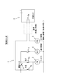
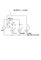
図1は、本発明の一実施形態に係るファン駆動回路1の説明図であり、ヒートポンプ装置である室内機および保護装置としての冷媒センサ2にそれぞれ電源が投入される前の状態のファン駆動回路1を示している。図2~4は、室内機および冷媒センサ2に電源が投入されているが、室内機の運転が停止中のファン駆動回路1の説明図である。図5~7は、室内機および冷媒センサ2に別電源が投入されており、室内機が運転中のファン駆動回路1の説明図である。
図1は、本発明の一実施形態に係るファン駆動回路1の説明図であり、ヒートポンプ装置である室内機および保護装置としての冷媒センサ2にそれぞれ電源が投入される前の状態のファン駆動回路1を示している。図2~4は、室内機および冷媒センサ2に電源が投入されているが、室内機の運転が停止中のファン駆動回路1の説明図である。図5~7は、室内機および冷媒センサ2に別電源が投入されており、室内機が運転中のファン駆動回路1の説明図である。
本実施形態に係るファン駆動回路1は、室内機および室外機を備えた空調機ないしは空気調和機における当該室内機内に設けられる室内ファンを駆動させる回路である。室内機は、前記室内ファン以外に熱交換器などを備えており、当該熱交換器により熱交換された調和空気を前記室内ファンにより吹出口から吹き出す。熱交換器は空気よりも比重の大きな微燃性ないしは可燃性冷媒である、例えばR32冷媒を使用して室内ファンにより機内に吸い込まれた空気との熱交換を行う。
本発明のファン駆動回路は、微燃性ないしは可燃性の冷媒が熱交換器または当該熱交換器に接続された冷媒配管から漏洩し、漏洩した冷媒が、室内機が配設されている居室などの空調室の床面などに滞留して可燃濃度に達するのを防止する回路である。したがって、本発明のファン駆動回路は、漏洩した冷媒が床面などに滞留する可能性が比較的大きいと考えられる床置き型の室内機に好適に適用することができるが、本発明はこれに限定されるものではなく、例えば天吊り型の室内機や、壁掛け型の室内機など他の室内機、さらには室外機や給湯機など他のヒートポンプ装置にも適用することができる。また、人が滞在する居室の空調を行う室内機だけでなく、サーバールームやクリーンルームなど主として機械や機器が配設された空間の空調を行う室内機にも適用することができる。
ファン駆動回路1と冷媒センサ2とは有線または無線により互いに通信可能に接続されている。無線による通信としては、例えば赤外線を利用して通信を行うことができる。冷媒センサ2は、例えば熱交換器の下方、または当該熱交換器と冷媒配管との接続部の下方など室内機内に設けることができるが、冷媒が漏洩した場合に当該冷媒が滞留すると想定される空調室内の適宜の場所に設けることもできる。後者の場合、通常、冷媒センサ1と室内機とは無線により互いに通信可能に接続される。
本実施形態における冷媒センサ2は、冷媒を検知すると、当該冷媒センサ2の接点2aが開き、冷媒センサ2を含む回路を開状態にする(図3参照)。
本実施形態における冷媒センサ2は、冷媒を検知すると、当該冷媒センサ2の接点2aが開き、冷媒センサ2を含む回路を開状態にする(図3参照)。
ファン駆動回路1は、冷媒センサ2が室内機に接続されているのを検知することができないという事象により室内ファンのファンモータ3を運転させる強制運転回路を備えている。前記強制運転回路は、室内機の運転スイッチ4よりも電源側で閉回路とすることができる。具体的に、強制運転回路は、運転スイッチ4よりも電源側において冷媒センサ2、ファンモータ3および第1リレー5を含む閉回路とすることができる。
第1リレー5は冷媒センサ2と連動して作動する。第1リレー5は、室内機の運転スイッチ4よりも電源側でファンモータ3を含む閉回路を構成するb接点5aを備えている。また、ファン駆動回路1は、第2リレー6を備えている。この第2リレー6は、室内機の制御側のリレーであり、通電されることで「閉」となるa接点6aを備えている。リモコンなどの操作により室内機、すなわち空調機の運転スイッチ4が「入」の状態になると、当該空調機におけるマイコンなどの制御部の指示により接点7が閉じられ、これにより第2リレー6が通電される。第2リレー6が通電されると、当該第2リレー6のa接点6aは閉状態となり、ファンモータ3は室内機の通常の制御に従い駆動する(図5参照)。
〔室内機停止中のファン駆動回路〕
図2は、室内機および冷媒センサ2に電源が投入されているが、室内機の運転が停止中であり、かつ、冷媒センサ2は冷媒を検知していない状態を示している。
室内機の運転が停止している状態において、図3に示されるように、冷媒センサ2が冷媒を検知すると、前述したように当該冷媒センサ2の接点2aが開き、第1リレー5は非通電状態になる。第1リレー5が非通電状態になると、当該第1リレー5のb接点5aは閉じられ、室内機は、マイコン制御による通常の運転は停止中であるが、ファンモータ3が駆動して室内ファンは強制運転させられる。このため、室内機が運転停止中であっても、冷媒センサ2が漏洩冷媒を検知すると室内ファンが強制運転させられるので、漏洩した冷媒を拡散させることができ、漏洩冷媒が空調室の床面などで滞留して可燃濃度に達するのを防止することができる。
図2は、室内機および冷媒センサ2に電源が投入されているが、室内機の運転が停止中であり、かつ、冷媒センサ2は冷媒を検知していない状態を示している。
室内機の運転が停止している状態において、図3に示されるように、冷媒センサ2が冷媒を検知すると、前述したように当該冷媒センサ2の接点2aが開き、第1リレー5は非通電状態になる。第1リレー5が非通電状態になると、当該第1リレー5のb接点5aは閉じられ、室内機は、マイコン制御による通常の運転は停止中であるが、ファンモータ3が駆動して室内ファンは強制運転させられる。このため、室内機が運転停止中であっても、冷媒センサ2が漏洩冷媒を検知すると室内ファンが強制運転させられるので、漏洩した冷媒を拡散させることができ、漏洩冷媒が空調室の床面などで滞留して可燃濃度に達するのを防止することができる。
本実施形態では、室内機の運転停止中に冷媒センサ2が冷媒を検知した場合だけでなく、室内機の運転停止中に冷媒センサ2と室内機との接続が外れて当該接続を検知することができないという事象になり、冷媒センサ2による漏洩冷媒の検知機能が発揮できない場合でも、室内ファンを強制運転させることができる。具体的に、図4に示されるように、冷媒センサ2が室内機から外れると第1リレー5は非通電状態になる。第1リレー5が非通電状態になると、当該第1リレー5のb接点5aは閉じられ、室内機は運転停止中ではあるが、ファンモータ3が駆動して室内ファンは強制運転させられる。
本実施形態に係るファン駆動回路は、室内機の運転停止中でも、フェールセーフにより安全側に働くように構成されている。これにより、冷媒センサ2と室内機との接続が外れている状態で万一冷媒が漏洩したとしても、室内ファンを強制運転させることで漏洩冷媒が空調室の床面などで滞留して可燃濃度に達するのを防止することができる。その結果、冷媒漏洩時における室内居住者や室内に配設されている機械および機器類の安全性を確保することができる。
〔室内機運転中のファン駆動回路〕
図5は、室内機が運転中であり、かつ、冷媒センサ2が冷媒を検知していない状態におけるファン駆動回路1を示している。前述したように、リモコンなどの操作により室内機、すなわち空調機の運転スイッチ4が「入」の状態になると、当該空調機におけるマイコンなどの制御部の指示により接点7が閉じられ、これにより第2リレー6が通電される。第2リレー6が通電されると、当該第2リレー6のa接点は閉状態となり、ファンモータ3は室内機の通常の制御に従い駆動し、また室外機における圧縮機の運転も可能な状態になる。
図5は、室内機が運転中であり、かつ、冷媒センサ2が冷媒を検知していない状態におけるファン駆動回路1を示している。前述したように、リモコンなどの操作により室内機、すなわち空調機の運転スイッチ4が「入」の状態になると、当該空調機におけるマイコンなどの制御部の指示により接点7が閉じられ、これにより第2リレー6が通電される。第2リレー6が通電されると、当該第2リレー6のa接点は閉状態となり、ファンモータ3は室内機の通常の制御に従い駆動し、また室外機における圧縮機の運転も可能な状態になる。
室内機が運転している状態において、図6に示されるように、冷媒センサ2が冷媒を検知すると、前述したように当該冷媒センサ2の接点2aが開き、第1リレー5は非通電状態になる。第1リレー5が非通電状態になると、当該第1リレー5のb接点5aは閉じられ、室内ファンは通常制御による運転モード(図5)から強制運転モードに切り替えられる。このため、例えば室内機が通常制御による運転モードにより「風速小」の状態で運転されていたとしても、冷媒センサ2が漏洩冷媒を検知すると室内ファンが、例えば「風速大」の状態で強制運転させられるので、漏洩した冷媒を拡散させることができ、漏洩冷媒が空調室の床面などで滞留して可燃濃度に達するのを防止することができる。
本実施形態では、室内機の運転中に冷媒センサ2が冷媒を検知した場合だけでなく、室内機の運転中に冷媒センサ2と室内機との接続が外れて当該接続を検知することができないという事象になり、冷媒センサ2による漏洩冷媒の検知機能が発揮できない場合でも、室内ファンを強制運転させることができる。具体的に、図7に示されるように、冷媒センサ2が室内機から外れると第1リレー5は非通電状態になる。第1リレー5が非通電状態になると、当該第1リレー5のb接点5aは閉じられ、室内ファンは通常制御による運転モード(図5)から強制運転モードに切り替えられ、強制運転させられる。なお、冷媒センサ2と室内機との接続が外れた状態では、接点7は「開」状態になり圧縮機の運転はできない。
本実施形態に係るファン駆動回路1は、フェールセーフにより安全側に働くように構成されている。これにより、冷媒センサ2と室内機との接続が外れている状態で万一冷媒が漏洩したとしても、室内ファンを強制運転させることで漏洩冷媒が空調室の床面などで滞留して可燃濃度に達するのを防止することができる。その結果、冷媒漏洩時における室内居住者や室内に配設されている機械および機器類の安全性を確保することができる。
本実施形態に係るファン駆動回路1は、保護装置としての冷媒センサ2が室内機に接続されておれば空調機を通常運転させることができるが、冷媒センサ2が室内機に接続されていなければ空調機を通常運転させることができないように構成されている。また、冷媒センサ2が漏洩冷媒を検知していない状態では室内ファンは通常制御により運転させられるが、冷媒センサ2が漏洩冷媒を検知すると室内ファンは強制運転させられるように構成されている。これにより、漏洩冷媒が可燃濃度に達するのを防止することができる。
〔その他の変形例〕
本発明は前述した実施形態に限定されるものではなく、特許請求の範囲内において種々の変更が可能である。
例えば、前述した実施形態では、保護装置として冷媒センサを採用し、この冷媒センサによって室内機からの漏洩冷媒が検知されると室内ファンを強制運転させて漏洩冷媒を拡散させるようにしているが、保護装置としては、かかる冷媒センサ以外に、例えば漏洩冷媒を検知すると音や光などで冷媒の漏洩をユーザーに知らせる警報器や、漏洩冷媒を含む室内の空気を強制的に室外に排出する換気装置を用いることもできる。冷媒センサ、警報器および換気装置は、単独で用いることもできるし、また、2つ以上を組み合わせて用いることもできる。
本発明は前述した実施形態に限定されるものではなく、特許請求の範囲内において種々の変更が可能である。
例えば、前述した実施形態では、保護装置として冷媒センサを採用し、この冷媒センサによって室内機からの漏洩冷媒が検知されると室内ファンを強制運転させて漏洩冷媒を拡散させるようにしているが、保護装置としては、かかる冷媒センサ以外に、例えば漏洩冷媒を検知すると音や光などで冷媒の漏洩をユーザーに知らせる警報器や、漏洩冷媒を含む室内の空気を強制的に室外に排出する換気装置を用いることもできる。冷媒センサ、警報器および換気装置は、単独で用いることもできるし、また、2つ以上を組み合わせて用いることもできる。
保護装置として警報器を用いる場合も、換気装置を用いる場合も、警報器または換気装置とヒートポンプ装置との接続が外れると、それぞれの機能を発揮することができず、前者の場合は、漏洩冷媒の存在をユーザーに知らせることができず、後者の場合は、漏れた冷媒が存在している空調室の空気を外部に排出することができない。しかし、本発明のファン駆動回路では、警報器または換気装置とヒートポンプ装置との接続が外れた場合に、フェールセーフでヒートポンプ装置のファンを運転させる強制運転回路を備えている。このため、警報器または換気装置とヒートポンプ装置との接続がはずれている状態で万一冷媒が漏洩したとしても、漏洩冷媒が空調室の床面などで滞留して可燃濃度に達するのを防止することができ、冷媒漏洩時における室内居住者などに対する安全性を確保することができる。また、換気装置や警報器がヒートポンプ装置に接続されている状態で当該ヒートポンプ装置の運転が可能であるので、冷媒の漏洩を抑制することができる。
1 :ファン駆動回路
2 :冷媒センサ
2a:接点
3 :ファンモータ
4 :運転スイッチ
5 :第1リレー
5a:b接点
6 :第2リレー
6a:a接点
7 :接点
2 :冷媒センサ
2a:接点
3 :ファンモータ
4 :運転スイッチ
5 :第1リレー
5a:b接点
6 :第2リレー
6a:a接点
7 :接点
Claims (4)
- 空気よりも比重の大きな微燃性ないしは可燃性冷媒を使用する熱交換器により熱交換された空気をファンにより吹出口から吹き出すヒートポンプ装置のファン駆動回路(1)であって、
前記ヒートポンプ装置からの漏洩冷媒が可燃濃度に達するのを防止する保護装置が当該ヒートポンプ装置に接続されているのを検知することができないという事象により前記ファンを運転させる強制運転回路を備えている、ヒートポンプ装置のファン駆動回路(1)。 - 前記ヒートポンプ装置の運転スイッチ(4)よりも電源側で前記強制運転回路を閉回路とする、請求項1に記載のヒートポンプ装置のファン駆動回路(1)。
- 前記保護装置がヒートポンプ装置に接続されている場合に前記強制運転回路を開状態にするリレー(5)を備えている、請求項1または請求項2に記載のヒートポンプ装置のファン駆動回路(1)。
- 前記保護装置が、前記熱交換器または当該熱交換器に接続される冷媒配管からの冷媒の漏洩を検知する冷媒センサ(2)である、請求項1~請求項3のいずれか1項に記載のヒートポンプ装置のファン駆動回路(1)。
Priority Applications (3)
| Application Number | Priority Date | Filing Date | Title |
|---|---|---|---|
| CN201680080693.7A CN108603707B (zh) | 2016-04-18 | 2016-12-22 | 热泵装置的风扇驱动回路 |
| US16/076,891 US10914482B2 (en) | 2016-04-18 | 2016-12-22 | Fan drive circuit for heat pump device |
| EP16899505.8A EP3447406B1 (en) | 2016-04-18 | 2016-12-22 | Heat pump device |
Applications Claiming Priority (2)
| Application Number | Priority Date | Filing Date | Title |
|---|---|---|---|
| JP2016-083088 | 2016-04-18 | ||
| JP2016083088A JP6876375B2 (ja) | 2016-04-18 | 2016-04-18 | ヒートポンプ装置のファン駆動回路 |
Publications (1)
| Publication Number | Publication Date |
|---|---|
| WO2017183234A1 true WO2017183234A1 (ja) | 2017-10-26 |
Family
ID=60116859
Family Applications (1)
| Application Number | Title | Priority Date | Filing Date |
|---|---|---|---|
| PCT/JP2016/088355 Ceased WO2017183234A1 (ja) | 2016-04-18 | 2016-12-22 | ヒートポンプ装置のファン駆動回路 |
Country Status (5)
| Country | Link |
|---|---|
| US (1) | US10914482B2 (ja) |
| EP (1) | EP3447406B1 (ja) |
| JP (1) | JP6876375B2 (ja) |
| CN (1) | CN108603707B (ja) |
| WO (1) | WO2017183234A1 (ja) |
Cited By (5)
| Publication number | Priority date | Publication date | Assignee | Title |
|---|---|---|---|---|
| US11686491B2 (en) | 2019-02-20 | 2023-06-27 | Johnson Controls Tyco IP Holdings LLP | Systems for refrigerant leak detection and management |
| JP2023534291A (ja) * | 2020-07-16 | 2023-08-08 | エマーソン クライメイト テクノロジーズ,インコーポレイテッド | 冷媒漏れセンサおよび緩和装置ならびに方法 |
| EP4686898A1 (en) | 2024-08-02 | 2026-02-04 | BDR Thermea Group B.V. | Controller, method, computer program product and non transitory computer readable medium for monitoring leakage of refrigerant, heat pump comprsing the controller |
| EP4686899A1 (en) | 2024-08-02 | 2026-02-04 | BDR Thermea Group B.V. | Controller, method, computer program product and non transitory computer readable medium for monitoring leakage of refrigerant, heat pump comprsing the controller |
| WO2026027765A1 (en) | 2024-08-02 | 2026-02-05 | Bdr Thermea Group B.V. | Controller for monitoring leakage of refrigerant |
Families Citing this family (16)
| Publication number | Priority date | Publication date | Assignee | Title |
|---|---|---|---|---|
| US10119738B2 (en) | 2014-09-26 | 2018-11-06 | Waterfurnace International Inc. | Air conditioning system with vapor injection compressor |
| US10871314B2 (en) | 2016-07-08 | 2020-12-22 | Climate Master, Inc. | Heat pump and water heater |
| US10866002B2 (en) | 2016-11-09 | 2020-12-15 | Climate Master, Inc. | Hybrid heat pump with improved dehumidification |
| US11280507B2 (en) * | 2017-11-16 | 2022-03-22 | Hitachi-Johnson Controls Air Conditioning, Inc. | Air-conditioner |
| US11592215B2 (en) | 2018-08-29 | 2023-02-28 | Waterfurnace International, Inc. | Integrated demand water heating using a capacity modulated heat pump with desuperheater |
| CN109296526B (zh) * | 2018-10-30 | 2024-04-05 | 苏州奥德高端装备股份有限公司 | 制冷机组断流保护结构 |
| EP3933288B1 (en) * | 2019-04-29 | 2023-10-25 | GD Midea Air-Conditioning Equipment Co., Ltd. | Air conditioner indoor unit |
| CA3081986A1 (en) | 2019-07-15 | 2021-01-15 | Climate Master, Inc. | Air conditioning system with capacity control and controlled hot water generation |
| JP7495594B2 (ja) * | 2020-02-05 | 2024-06-05 | ダイキン工業株式会社 | 空気調和システム |
| EP3875861B1 (en) * | 2020-03-06 | 2023-05-17 | Daikin Industries, Ltd. | Air-conditioner, air-conditioning system, and method for monitoring air-conditioner |
| US11920805B2 (en) * | 2021-02-01 | 2024-03-05 | Goodman Manufacturing Company LP | Systems and methods for air temperature control using A2L refrigerants |
| US12235001B2 (en) | 2021-02-01 | 2025-02-25 | Goodman Manufacturing Company LP | Systems and methods for air temperature control including R-454b sensors |
| US11662110B2 (en) | 2021-02-01 | 2023-05-30 | Goodman Manufacturing Company LP | Systems and methods for air temperature control including R-32 sensors |
| US11668483B2 (en) | 2021-02-01 | 2023-06-06 | Goodman Manufacturing Company LP | Systems and methods for air temperature control including A2L sensors |
| US12181189B2 (en) | 2021-11-10 | 2024-12-31 | Climate Master, Inc. | Ceiling-mountable heat pump system |
| US20240068685A1 (en) * | 2022-08-30 | 2024-02-29 | Rheem Manufacturing Company | Safety System For Air Handling Unit |
Citations (7)
| Publication number | Priority date | Publication date | Assignee | Title |
|---|---|---|---|---|
| JPH06269280A (ja) * | 1993-03-21 | 1994-09-27 | Mitsubishi Agricult Mach Co Ltd | 製麹装置における品温制御開始方法 |
| JP2000146393A (ja) * | 1998-11-05 | 2000-05-26 | Hitachi Ltd | 冷凍装置 |
| JP2002005548A (ja) * | 2000-06-19 | 2002-01-09 | Mitsubishi Electric Corp | 可燃性冷媒使用の家電機器 |
| JP2008201213A (ja) * | 2007-02-19 | 2008-09-04 | Yamaha Marine Co Ltd | 船舶推進機及び船舶 |
| JP2011121736A (ja) * | 2009-12-11 | 2011-06-23 | Hitachi Ltd | エレベータ制御装置 |
| JP2012229863A (ja) * | 2011-04-26 | 2012-11-22 | Hoshizaki Electric Co Ltd | 製氷機の運転方法 |
| JP2014126253A (ja) * | 2012-12-26 | 2014-07-07 | Noritz Corp | ヒートポンプ装置 |
Family Cites Families (11)
| Publication number | Priority date | Publication date | Assignee | Title |
|---|---|---|---|---|
| JPH04225769A (ja) * | 1990-12-26 | 1992-08-14 | Mitsubishi Heavy Ind Ltd | ガス漏れ診断装置付き冷凍装置 |
| JPH05133629A (ja) * | 1991-11-13 | 1993-05-28 | Mitsubishi Heavy Ind Ltd | スクロール型圧縮機を備えた冷却装置 |
| JPH1024825A (ja) | 1996-07-08 | 1998-01-27 | Denso Corp | ブレーキ液還流ポンプ及びそのポンプを備えたブレーキ制御装置 |
| JPH1137619A (ja) | 1997-07-16 | 1999-02-12 | Daikin Ind Ltd | 自然冷媒を用いた空気調和装置 |
| JPH11190564A (ja) * | 1997-12-26 | 1999-07-13 | Tokyo Gas Co Ltd | 空気調和装置 |
| JP4540992B2 (ja) | 2004-01-13 | 2010-09-08 | 矢崎総業株式会社 | ガス検出装置 |
| JP2006115592A (ja) | 2004-10-14 | 2006-04-27 | Silex Technology Inc | 非接触型充電装置 |
| WO2012144524A1 (ja) * | 2011-04-21 | 2012-10-26 | ホシザキ電機株式会社 | 製氷機の運転方法 |
| JP5935369B2 (ja) * | 2012-02-15 | 2016-06-15 | ダイキン工業株式会社 | 空調機の通信線断線検知システム |
| EP3159633B1 (en) | 2014-06-19 | 2019-08-28 | Mitsubishi Electric Corporation | Indoor unit for air-conditioning device, and air-conditioning device provided with said indoor unit |
| ES2715766T3 (es) * | 2015-03-31 | 2019-06-06 | Daikin Ind Ltd | Acondicionador de aire |
-
2016
- 2016-04-18 JP JP2016083088A patent/JP6876375B2/ja active Active
- 2016-12-22 US US16/076,891 patent/US10914482B2/en active Active
- 2016-12-22 CN CN201680080693.7A patent/CN108603707B/zh active Active
- 2016-12-22 EP EP16899505.8A patent/EP3447406B1/en active Active
- 2016-12-22 WO PCT/JP2016/088355 patent/WO2017183234A1/ja not_active Ceased
Patent Citations (7)
| Publication number | Priority date | Publication date | Assignee | Title |
|---|---|---|---|---|
| JPH06269280A (ja) * | 1993-03-21 | 1994-09-27 | Mitsubishi Agricult Mach Co Ltd | 製麹装置における品温制御開始方法 |
| JP2000146393A (ja) * | 1998-11-05 | 2000-05-26 | Hitachi Ltd | 冷凍装置 |
| JP2002005548A (ja) * | 2000-06-19 | 2002-01-09 | Mitsubishi Electric Corp | 可燃性冷媒使用の家電機器 |
| JP2008201213A (ja) * | 2007-02-19 | 2008-09-04 | Yamaha Marine Co Ltd | 船舶推進機及び船舶 |
| JP2011121736A (ja) * | 2009-12-11 | 2011-06-23 | Hitachi Ltd | エレベータ制御装置 |
| JP2012229863A (ja) * | 2011-04-26 | 2012-11-22 | Hoshizaki Electric Co Ltd | 製氷機の運転方法 |
| JP2014126253A (ja) * | 2012-12-26 | 2014-07-07 | Noritz Corp | ヒートポンプ装置 |
Non-Patent Citations (1)
| Title |
|---|
| See also references of EP3447406A4 * |
Cited By (7)
| Publication number | Priority date | Publication date | Assignee | Title |
|---|---|---|---|---|
| US11686491B2 (en) | 2019-02-20 | 2023-06-27 | Johnson Controls Tyco IP Holdings LLP | Systems for refrigerant leak detection and management |
| JP2023534291A (ja) * | 2020-07-16 | 2023-08-08 | エマーソン クライメイト テクノロジーズ,インコーポレイテッド | 冷媒漏れセンサおよび緩和装置ならびに方法 |
| JP7551894B2 (ja) | 2020-07-16 | 2024-09-17 | コープランド エルピー | 冷媒漏れセンサおよび緩和装置ならびに方法 |
| EP4686898A1 (en) | 2024-08-02 | 2026-02-04 | BDR Thermea Group B.V. | Controller, method, computer program product and non transitory computer readable medium for monitoring leakage of refrigerant, heat pump comprsing the controller |
| EP4686899A1 (en) | 2024-08-02 | 2026-02-04 | BDR Thermea Group B.V. | Controller, method, computer program product and non transitory computer readable medium for monitoring leakage of refrigerant, heat pump comprsing the controller |
| WO2026027765A1 (en) | 2024-08-02 | 2026-02-05 | Bdr Thermea Group B.V. | Controller for monitoring leakage of refrigerant |
| WO2026027766A1 (en) | 2024-08-02 | 2026-02-05 | Bdr Thermea Group B.V. | Heat pump with malfunction detection system |
Also Published As
| Publication number | Publication date |
|---|---|
| EP3447406A1 (en) | 2019-02-27 |
| JP6876375B2 (ja) | 2021-05-26 |
| JP2017194187A (ja) | 2017-10-26 |
| EP3447406A4 (en) | 2019-12-25 |
| US20190086111A1 (en) | 2019-03-21 |
| US10914482B2 (en) | 2021-02-09 |
| CN108603707B (zh) | 2021-06-15 |
| CN108603707A (zh) | 2018-09-28 |
| EP3447406B1 (en) | 2024-04-10 |
Similar Documents
| Publication | Publication Date | Title |
|---|---|---|
| JP6876375B2 (ja) | ヒートポンプ装置のファン駆動回路 | |
| US10488072B2 (en) | Air conditioning system with leak protection control | |
| US9459013B2 (en) | Air-conditioning apparatus with safety measure for ventilation of inflammable refrigerant from heat exchanger | |
| JP4599699B2 (ja) | 空気調和機 | |
| JP5804027B2 (ja) | 空気調和機の室内機 | |
| US11971184B2 (en) | Air mover refrigerant leak detection and risk mitigation | |
| WO2021065571A1 (ja) | 空調換気システム | |
| JP2016211762A (ja) | 空調換気システム | |
| JP7713638B2 (ja) | 空気調和装置 | |
| JP6851500B2 (ja) | ダクト式空気調和機 | |
| JP2019060517A (ja) | 空気調和機 | |
| CN110603412A (zh) | 空调系统及其制冷剂量设定方法 | |
| JP6519373B2 (ja) | 空気調和装置の室内機 | |
| WO2017187483A1 (ja) | 室内機および空気調和装置 | |
| JP2020183829A (ja) | 空調システム及び補助ファン | |
| JP2015094512A (ja) | 床置型空気調和機の室内機 | |
| JP2019174110A (ja) | 空調換気システム | |
| JP6431366B2 (ja) | 空気調和システム | |
| JP6571466B2 (ja) | 空気調和機 | |
| JP6914794B2 (ja) | 空気調和機 | |
| JP2001012763A (ja) | 空調換気システム | |
| JP2015017802A (ja) | 天井埋込型空気調和機 | |
| CN204534839U (zh) | 落地型空调室内单元 | |
| KR20140067679A (ko) | 전기 라디에이터 냉온풍기 | |
| JP2010164200A (ja) | 換気空調装置 |
Legal Events
| Date | Code | Title | Description |
|---|---|---|---|
| NENP | Non-entry into the national phase |
Ref country code: DE |
|
| WWE | Wipo information: entry into national phase |
Ref document number: 2016899505 Country of ref document: EP |
|
| ENP | Entry into the national phase |
Ref document number: 2016899505 Country of ref document: EP Effective date: 20181119 |
|
| 121 | Ep: the epo has been informed by wipo that ep was designated in this application |
Ref document number: 16899505 Country of ref document: EP Kind code of ref document: A1 |