WO2017175682A1 - ガラス板構成体 - Google Patents
ガラス板構成体 Download PDFInfo
- Publication number
- WO2017175682A1 WO2017175682A1 PCT/JP2017/013683 JP2017013683W WO2017175682A1 WO 2017175682 A1 WO2017175682 A1 WO 2017175682A1 JP 2017013683 W JP2017013683 W JP 2017013683W WO 2017175682 A1 WO2017175682 A1 WO 2017175682A1
- Authority
- WO
- WIPO (PCT)
- Prior art keywords
- glass plate
- glass
- plate structure
- structure according
- pair
- Prior art date
Links
Images


Classifications
-
- B—PERFORMING OPERATIONS; TRANSPORTING
- B32—LAYERED PRODUCTS
- B32B—LAYERED PRODUCTS, i.e. PRODUCTS BUILT-UP OF STRATA OF FLAT OR NON-FLAT, e.g. CELLULAR OR HONEYCOMB, FORM
- B32B17/00—Layered products essentially comprising sheet glass, or glass, slag, or like fibres
- B32B17/06—Layered products essentially comprising sheet glass, or glass, slag, or like fibres comprising glass as the main or only constituent of a layer, next to another layer of a specific material
-
- B—PERFORMING OPERATIONS; TRANSPORTING
- B32—LAYERED PRODUCTS
- B32B—LAYERED PRODUCTS, i.e. PRODUCTS BUILT-UP OF STRATA OF FLAT OR NON-FLAT, e.g. CELLULAR OR HONEYCOMB, FORM
- B32B1/00—Layered products having a general shape other than plane
-
- B—PERFORMING OPERATIONS; TRANSPORTING
- B32—LAYERED PRODUCTS
- B32B—LAYERED PRODUCTS, i.e. PRODUCTS BUILT-UP OF STRATA OF FLAT OR NON-FLAT, e.g. CELLULAR OR HONEYCOMB, FORM
- B32B11/00—Layered products comprising a layer of bituminous or tarry substances
- B32B11/04—Layered products comprising a layer of bituminous or tarry substances comprising such bituminous or tarry substance as the main or only constituent of a layer, which is next to another layer of the same or of a different material
-
- B—PERFORMING OPERATIONS; TRANSPORTING
- B32—LAYERED PRODUCTS
- B32B—LAYERED PRODUCTS, i.e. PRODUCTS BUILT-UP OF STRATA OF FLAT OR NON-FLAT, e.g. CELLULAR OR HONEYCOMB, FORM
- B32B27/00—Layered products comprising a layer of synthetic resin
- B32B27/28—Layered products comprising a layer of synthetic resin comprising synthetic resins not wholly covered by any one of the sub-groups B32B27/30 - B32B27/42
- B32B27/281—Layered products comprising a layer of synthetic resin comprising synthetic resins not wholly covered by any one of the sub-groups B32B27/30 - B32B27/42 comprising polyimides
-
- B—PERFORMING OPERATIONS; TRANSPORTING
- B32—LAYERED PRODUCTS
- B32B—LAYERED PRODUCTS, i.e. PRODUCTS BUILT-UP OF STRATA OF FLAT OR NON-FLAT, e.g. CELLULAR OR HONEYCOMB, FORM
- B32B27/00—Layered products comprising a layer of synthetic resin
- B32B27/30—Layered products comprising a layer of synthetic resin comprising vinyl (co)polymers; comprising acrylic (co)polymers
-
- B—PERFORMING OPERATIONS; TRANSPORTING
- B32—LAYERED PRODUCTS
- B32B—LAYERED PRODUCTS, i.e. PRODUCTS BUILT-UP OF STRATA OF FLAT OR NON-FLAT, e.g. CELLULAR OR HONEYCOMB, FORM
- B32B7/00—Layered products characterised by the relation between layers; Layered products characterised by the relative orientation of features between layers, or by the relative values of a measurable parameter between layers, i.e. products comprising layers having different physical, chemical or physicochemical properties; Layered products characterised by the interconnection of layers
- B32B7/04—Interconnection of layers
- B32B7/12—Interconnection of layers using interposed adhesives or interposed materials with bonding properties
-
- C—CHEMISTRY; METALLURGY
- C03—GLASS; MINERAL OR SLAG WOOL
- C03C—CHEMICAL COMPOSITION OF GLASSES, GLAZES OR VITREOUS ENAMELS; SURFACE TREATMENT OF GLASS; SURFACE TREATMENT OF FIBRES OR FILAMENTS MADE FROM GLASS, MINERALS OR SLAGS; JOINING GLASS TO GLASS OR OTHER MATERIALS
- C03C21/00—Treatment of glass, not in the form of fibres or filaments, by diffusing ions or metals in the surface
-
- C—CHEMISTRY; METALLURGY
- C03—GLASS; MINERAL OR SLAG WOOL
- C03C—CHEMICAL COMPOSITION OF GLASSES, GLAZES OR VITREOUS ENAMELS; SURFACE TREATMENT OF GLASS; SURFACE TREATMENT OF FIBRES OR FILAMENTS MADE FROM GLASS, MINERALS OR SLAGS; JOINING GLASS TO GLASS OR OTHER MATERIALS
- C03C27/00—Joining pieces of glass to pieces of other inorganic material; Joining glass to glass other than by fusing
- C03C27/06—Joining glass to glass by processes other than fusing
-
- G—PHYSICS
- G11—INFORMATION STORAGE
- G11B—INFORMATION STORAGE BASED ON RELATIVE MOVEMENT BETWEEN RECORD CARRIER AND TRANSDUCER
- G11B5/00—Recording by magnetisation or demagnetisation of a record carrier; Reproducing by magnetic means; Record carriers therefor
- G11B5/62—Record carriers characterised by the selection of the material
- G11B5/73—Base layers, i.e. all non-magnetic layers lying under a lowermost magnetic recording layer, e.g. including any non-magnetic layer in between a first magnetic recording layer and either an underlying substrate or a soft magnetic underlayer
- G11B5/739—Magnetic recording media substrates
- G11B5/73911—Inorganic substrates
- G11B5/73921—Glass or ceramic substrates
-
- H—ELECTRICITY
- H04—ELECTRIC COMMUNICATION TECHNIQUE
- H04R—LOUDSPEAKERS, MICROPHONES, GRAMOPHONE PICK-UPS OR LIKE ACOUSTIC ELECTROMECHANICAL TRANSDUCERS; DEAF-AID SETS; PUBLIC ADDRESS SYSTEMS
- H04R7/00—Diaphragms for electromechanical transducers; Cones
- H04R7/02—Diaphragms for electromechanical transducers; Cones characterised by the construction
- H04R7/04—Plane diaphragms
- H04R7/06—Plane diaphragms comprising a plurality of sections or layers
-
- B—PERFORMING OPERATIONS; TRANSPORTING
- B32—LAYERED PRODUCTS
- B32B—LAYERED PRODUCTS, i.e. PRODUCTS BUILT-UP OF STRATA OF FLAT OR NON-FLAT, e.g. CELLULAR OR HONEYCOMB, FORM
- B32B17/00—Layered products essentially comprising sheet glass, or glass, slag, or like fibres
- B32B17/06—Layered products essentially comprising sheet glass, or glass, slag, or like fibres comprising glass as the main or only constituent of a layer, next to another layer of a specific material
- B32B17/10—Layered products essentially comprising sheet glass, or glass, slag, or like fibres comprising glass as the main or only constituent of a layer, next to another layer of a specific material of synthetic resin
- B32B17/10005—Layered products essentially comprising sheet glass, or glass, slag, or like fibres comprising glass as the main or only constituent of a layer, next to another layer of a specific material of synthetic resin laminated safety glass or glazing
- B32B17/10009—Layered products essentially comprising sheet glass, or glass, slag, or like fibres comprising glass as the main or only constituent of a layer, next to another layer of a specific material of synthetic resin laminated safety glass or glazing characterized by the number, the constitution or treatment of glass sheets
- B32B17/10082—Properties of the bulk of a glass sheet
-
- B—PERFORMING OPERATIONS; TRANSPORTING
- B32—LAYERED PRODUCTS
- B32B—LAYERED PRODUCTS, i.e. PRODUCTS BUILT-UP OF STRATA OF FLAT OR NON-FLAT, e.g. CELLULAR OR HONEYCOMB, FORM
- B32B17/00—Layered products essentially comprising sheet glass, or glass, slag, or like fibres
- B32B17/06—Layered products essentially comprising sheet glass, or glass, slag, or like fibres comprising glass as the main or only constituent of a layer, next to another layer of a specific material
- B32B17/10—Layered products essentially comprising sheet glass, or glass, slag, or like fibres comprising glass as the main or only constituent of a layer, next to another layer of a specific material of synthetic resin
- B32B17/10005—Layered products essentially comprising sheet glass, or glass, slag, or like fibres comprising glass as the main or only constituent of a layer, next to another layer of a specific material of synthetic resin laminated safety glass or glazing
- B32B17/10009—Layered products essentially comprising sheet glass, or glass, slag, or like fibres comprising glass as the main or only constituent of a layer, next to another layer of a specific material of synthetic resin laminated safety glass or glazing characterized by the number, the constitution or treatment of glass sheets
- B32B17/10128—Treatment of at least one glass sheet
- B32B17/10137—Chemical strengthening
-
- B—PERFORMING OPERATIONS; TRANSPORTING
- B32—LAYERED PRODUCTS
- B32B—LAYERED PRODUCTS, i.e. PRODUCTS BUILT-UP OF STRATA OF FLAT OR NON-FLAT, e.g. CELLULAR OR HONEYCOMB, FORM
- B32B17/00—Layered products essentially comprising sheet glass, or glass, slag, or like fibres
- B32B17/06—Layered products essentially comprising sheet glass, or glass, slag, or like fibres comprising glass as the main or only constituent of a layer, next to another layer of a specific material
- B32B17/10—Layered products essentially comprising sheet glass, or glass, slag, or like fibres comprising glass as the main or only constituent of a layer, next to another layer of a specific material of synthetic resin
- B32B17/10005—Layered products essentially comprising sheet glass, or glass, slag, or like fibres comprising glass as the main or only constituent of a layer, next to another layer of a specific material of synthetic resin laminated safety glass or glazing
- B32B17/10165—Functional features of the laminated safety glass or glazing
- B32B17/10321—Laminated safety glass or glazing containing liquid layers
-
- B—PERFORMING OPERATIONS; TRANSPORTING
- B32—LAYERED PRODUCTS
- B32B—LAYERED PRODUCTS, i.e. PRODUCTS BUILT-UP OF STRATA OF FLAT OR NON-FLAT, e.g. CELLULAR OR HONEYCOMB, FORM
- B32B17/00—Layered products essentially comprising sheet glass, or glass, slag, or like fibres
- B32B17/06—Layered products essentially comprising sheet glass, or glass, slag, or like fibres comprising glass as the main or only constituent of a layer, next to another layer of a specific material
- B32B17/10—Layered products essentially comprising sheet glass, or glass, slag, or like fibres comprising glass as the main or only constituent of a layer, next to another layer of a specific material of synthetic resin
- B32B17/10005—Layered products essentially comprising sheet glass, or glass, slag, or like fibres comprising glass as the main or only constituent of a layer, next to another layer of a specific material of synthetic resin laminated safety glass or glazing
- B32B17/10165—Functional features of the laminated safety glass or glazing
- B32B17/10431—Specific parts for the modulation of light incorporated into the laminated safety glass or glazing
- B32B17/1044—Invariable transmission
-
- B—PERFORMING OPERATIONS; TRANSPORTING
- B32—LAYERED PRODUCTS
- B32B—LAYERED PRODUCTS, i.e. PRODUCTS BUILT-UP OF STRATA OF FLAT OR NON-FLAT, e.g. CELLULAR OR HONEYCOMB, FORM
- B32B2255/00—Coating on the layer surface
- B32B2255/20—Inorganic coating
-
- B—PERFORMING OPERATIONS; TRANSPORTING
- B32—LAYERED PRODUCTS
- B32B—LAYERED PRODUCTS, i.e. PRODUCTS BUILT-UP OF STRATA OF FLAT OR NON-FLAT, e.g. CELLULAR OR HONEYCOMB, FORM
- B32B2255/00—Coating on the layer surface
- B32B2255/24—Organic non-macromolecular coating
-
- B—PERFORMING OPERATIONS; TRANSPORTING
- B32—LAYERED PRODUCTS
- B32B—LAYERED PRODUCTS, i.e. PRODUCTS BUILT-UP OF STRATA OF FLAT OR NON-FLAT, e.g. CELLULAR OR HONEYCOMB, FORM
- B32B2255/00—Coating on the layer surface
- B32B2255/26—Polymeric coating
-
- B—PERFORMING OPERATIONS; TRANSPORTING
- B32—LAYERED PRODUCTS
- B32B—LAYERED PRODUCTS, i.e. PRODUCTS BUILT-UP OF STRATA OF FLAT OR NON-FLAT, e.g. CELLULAR OR HONEYCOMB, FORM
- B32B2307/00—Properties of the layers or laminate
- B32B2307/10—Properties of the layers or laminate having particular acoustical properties
-
- B—PERFORMING OPERATIONS; TRANSPORTING
- B32—LAYERED PRODUCTS
- B32B—LAYERED PRODUCTS, i.e. PRODUCTS BUILT-UP OF STRATA OF FLAT OR NON-FLAT, e.g. CELLULAR OR HONEYCOMB, FORM
- B32B2307/00—Properties of the layers or laminate
- B32B2307/40—Properties of the layers or laminate having particular optical properties
- B32B2307/402—Coloured
-
- B—PERFORMING OPERATIONS; TRANSPORTING
- B32—LAYERED PRODUCTS
- B32B—LAYERED PRODUCTS, i.e. PRODUCTS BUILT-UP OF STRATA OF FLAT OR NON-FLAT, e.g. CELLULAR OR HONEYCOMB, FORM
- B32B2307/00—Properties of the layers or laminate
- B32B2307/40—Properties of the layers or laminate having particular optical properties
- B32B2307/412—Transparent
-
- B—PERFORMING OPERATIONS; TRANSPORTING
- B32—LAYERED PRODUCTS
- B32B—LAYERED PRODUCTS, i.e. PRODUCTS BUILT-UP OF STRATA OF FLAT OR NON-FLAT, e.g. CELLULAR OR HONEYCOMB, FORM
- B32B2307/00—Properties of the layers or laminate
- B32B2307/40—Properties of the layers or laminate having particular optical properties
- B32B2307/422—Luminescent, fluorescent, phosphorescent
-
- B—PERFORMING OPERATIONS; TRANSPORTING
- B32—LAYERED PRODUCTS
- B32B—LAYERED PRODUCTS, i.e. PRODUCTS BUILT-UP OF STRATA OF FLAT OR NON-FLAT, e.g. CELLULAR OR HONEYCOMB, FORM
- B32B2307/00—Properties of the layers or laminate
- B32B2307/70—Other properties
- B32B2307/72—Density
-
- B—PERFORMING OPERATIONS; TRANSPORTING
- B32—LAYERED PRODUCTS
- B32B—LAYERED PRODUCTS, i.e. PRODUCTS BUILT-UP OF STRATA OF FLAT OR NON-FLAT, e.g. CELLULAR OR HONEYCOMB, FORM
- B32B2429/00—Carriers for sound or information
-
- B—PERFORMING OPERATIONS; TRANSPORTING
- B32—LAYERED PRODUCTS
- B32B—LAYERED PRODUCTS, i.e. PRODUCTS BUILT-UP OF STRATA OF FLAT OR NON-FLAT, e.g. CELLULAR OR HONEYCOMB, FORM
- B32B2607/00—Walls, panels
-
- C—CHEMISTRY; METALLURGY
- C03—GLASS; MINERAL OR SLAG WOOL
- C03C—CHEMICAL COMPOSITION OF GLASSES, GLAZES OR VITREOUS ENAMELS; SURFACE TREATMENT OF GLASS; SURFACE TREATMENT OF FIBRES OR FILAMENTS MADE FROM GLASS, MINERALS OR SLAGS; JOINING GLASS TO GLASS OR OTHER MATERIALS
- C03C3/00—Glass compositions
- C03C3/04—Glass compositions containing silica
- C03C3/076—Glass compositions containing silica with 40% to 90% silica, by weight
- C03C3/083—Glass compositions containing silica with 40% to 90% silica, by weight containing aluminium oxide or an iron compound
- C03C3/085—Glass compositions containing silica with 40% to 90% silica, by weight containing aluminium oxide or an iron compound containing an oxide of a divalent metal
- C03C3/087—Glass compositions containing silica with 40% to 90% silica, by weight containing aluminium oxide or an iron compound containing an oxide of a divalent metal containing calcium oxide, e.g. common sheet or container glass
-
- H—ELECTRICITY
- H04—ELECTRIC COMMUNICATION TECHNIQUE
- H04R—LOUDSPEAKERS, MICROPHONES, GRAMOPHONE PICK-UPS OR LIKE ACOUSTIC ELECTROMECHANICAL TRANSDUCERS; DEAF-AID SETS; PUBLIC ADDRESS SYSTEMS
- H04R2307/00—Details of diaphragms or cones for electromechanical transducers, their suspension or their manufacture covered by H04R7/00 or H04R31/003, not provided for in any of its subgroups
- H04R2307/023—Diaphragms comprising ceramic-like materials, e.g. pure ceramic, glass, boride, nitride, carbide, mica and carbon materials
Definitions
- the present invention relates to a glass plate structure having good acoustic performance, and also relates to a diaphragm, an opening member and a glass substrate for a magnetic recording medium using the glass plate structure.
- cone paper or resin is used as a diaphragm for a speaker or a microphone. Since these materials have a large loss coefficient and are less likely to cause resonance vibration, they are said to have good sound reproduction performance in the audible range. However, since these materials all have low sound velocity values, it is difficult for material vibrations to follow the sound wave frequency when excited at high frequencies, and split vibrations are likely to occur. Therefore, a desired sound pressure is difficult to be generated particularly in a high frequency region.
- the band that is required to be reproduced is a high-frequency region of 20 kHz or higher, and although it is a band that is difficult to hear with human ears, there are things that are closer to emotions, such as a strong sense of reality. Therefore, it is desirable that the sound wave vibration in the band can be faithfully reproduced.
- cone paper or resin instead of cone paper or resin, it is conceivable to use materials such as metals, ceramics, and glass that have a high speed of sound propagation to the material.
- materials such as metals, ceramics, and glass that have a high speed of sound propagation to the material.
- these materials generally have a loss factor as small as about 1/10 to 1/100 of paper, unintended reverberation tends to remain.
- a significant timbre degradation can occur due to the occurrence of a resonance mode when excited at the natural frequency of the member.
- Non-Patent Document 1 A laminated glass having a polybutyl polymer layer having a thickness of 0.5 mm between two glass plates is known as a diaphragm for a speaker (Non-Patent Document 1).
- the diaphragm is difficult to reproduce in a high frequency region.
- an object of the present invention is to provide a glass plate structure having good acoustic performance.
- the present inventor has found that the above problem can be solved by using a predetermined glass plate structure, and has completed the present invention.
- the present invention is as follows.
- ⁇ 1> A glass plate structure having a loss coefficient of 1 ⁇ 10 ⁇ 2 or more at 25 ° C. and a longitudinal wave sound velocity value of 5.5 ⁇ 10 3 m / s or more in the plate thickness direction.
- the glass plate structure according to ⁇ 1> including two or more glass plates and including a liquid layer between at least a pair of glass plates among the glass plates.
- the thickness of the liquid layer is When the total thickness of the pair of glass plates is 1 mm or less, it is 1/10 or less of the total thickness of the pair of glass plates, When the total thickness of the pair of glass plates exceeds 1 mm, the glass plate structure according to ⁇ 2>, which is 100 ⁇ m or less.
- ⁇ 4> the a viscosity coefficient 1 ⁇ 10 -4 ⁇ 1 ⁇ 10 3 Pa ⁇ s at 25 ° C. a liquid layer, and a surface tension at 25 ° C. is 15 ⁇ 80 mN / m, the ⁇ 2> or The glass plate structure as described in ⁇ 3>.
- ⁇ 5> The glass according to any one of ⁇ 2> to ⁇ 4>, wherein the specific elastic modulus of at least one pair of the glass plates is 2.5 ⁇ 10 7 m 2 / s 2 or more. Board construction.
- the resonance frequency of one glass plate A is Qa
- the half-value width of the resonance amplitude is wa
- the resonance frequency of the other glass plate B is Qb
- resonance is Qb
- ⁇ 8> The glass plate structure according to any one of ⁇ 2> to ⁇ 7>, wherein the two glass plates constituting the pair of glass plates each have a thickness of 0.01 to 15 mm.
- the liquid layer contains at least one selected from the group consisting of propylene glycol, dimethyl silicone oil, methyl phenyl silicone oil, methyl hydrogen silicone oil, and modified silicone oil
- ⁇ 11> The glass plate structure according to any one of ⁇ 1> to ⁇ 10>, wherein the visible light transmittance is 60% or more.
- ⁇ 12> The glass plate structure according to any one of ⁇ 2> to ⁇ 11>, including three or more glass plates.
- ⁇ 13> The glass plate structure according to any one of ⁇ 2> to ⁇ 12>, wherein at least one of the glass plates and at least one of the liquid layers are colored.
- ⁇ 14> The glass plate structure according to any one of ⁇ 2> to ⁇ 13>, wherein the liquid layer contains a fluorescent material.
- ⁇ 15> The glass plate structure according to any one of ⁇ 1> to ⁇ 14>, wherein a coating or a film is formed on at least one outermost surface of the glass plate structure.
- ⁇ 16> The glass plate structure according to any one of ⁇ 1> to ⁇ 15>, wherein the glass plate structure has a curved shape.
- ⁇ 17> The glass plate structure according to any one of ⁇ 2> to ⁇ 16>, wherein a difference between a refractive index of the liquid layer and a refractive index of the pair of glass plates is 0.2 or less. .
- ⁇ 18> The glass plate structure according to any one of ⁇ 1> to ⁇ 17>, wherein at least a part of the outer peripheral end surface of the glass plate structure is sealed with a member that does not interfere with vibration of the glass plate structure.
- ⁇ 19> Including two or more glass plates, including a liquid layer between at least a pair of glass plates among the glass plates, The thickness of the liquid layer is When the total thickness of the pair of glass plates is 1 mm or less, it is 1/10 or less of the total thickness of the pair of glass plates, When the total thickness of the pair of glass plates exceeds 1 mm, the glass plate structure is 100 ⁇ m or less.
- ⁇ 22> A glass substrate for a magnetic recording medium, using the glass plate structure according to any one of ⁇ 1> to ⁇ 19>.
- the present invention sound reproducibility is improved from a low frequency range to a high frequency range in a diaphragm used for a speaker, a microphone, an earphone, a mobile device, or the like.
- a diaphragm used for a speaker a microphone
- an earphone a mobile device, or the like.
- the vibration damping effect can be enhanced in applications such as glass substrates for magnetic recording media.
- FIG. 1 is a cross-sectional view showing an example of the glass plate structure of the present invention.
- FIG. 2 is a cross-sectional view showing another example of the glass plate structure of the present invention.
- FIG. 3 is a cross-sectional view showing another example of the glass plate structure of the present invention.
- FIG. 4 is a perspective view showing still another example of the glass plate structure of the present invention.
- FIG. 5A is a plan view of the glass plate structure shown in FIG. 4, and
- FIG. 5B is a cross-sectional view taken along the line A-A ′ in FIG.
- FIG. 6 is a cross-sectional view showing another example of the glass plate structure of the present invention.
- FIG. 7A is a plan view showing another example of the glass plate structure of the present invention, and FIG.
- FIG. 7B is a cross-sectional view taken along line A-A ′ in FIG.
- FIG. 8A is a plan view showing another example of the glass plate structure of the present invention
- FIG. 8B is a cross-sectional view taken along line A-A ′ in FIG.
- FIG. 9 is a cross-sectional view showing still another example of the glass plate structure of the present invention.
- ⁇ indicating a numerical range is used to mean that the numerical values described before and after it are included as a lower limit value and an upper limit value.
- the glass plate structure according to the present invention has a loss coefficient at 25 ° C. of 1 ⁇ 10 ⁇ 2 or more and a longitudinal wave sound velocity value in the plate thickness direction of 5.5 ⁇ 10 3 m / s or more. To do.
- a large loss coefficient means that the vibration damping ability is large.
- the loss factor a value calculated by the half-width method is used. Represented by ⁇ W / f ⁇ , where W is the frequency width of a point at which the resonance frequency f of the material is -3 dB lower than the peak value of amplitude h (that is, the point at the maximum amplitude of -3 [dB]). Define the value as the loss factor. In order to suppress the resonance, it is only necessary to increase the loss factor, that is, the frequency width W becomes relatively large with respect to the amplitude h, which means that the peak becomes broad.
- the loss factor is a specific value of the material and the like, and for example, in the case of a single glass plate, it varies depending on the composition and relative density.
- the loss factor can be measured by a dynamic elastic modulus test method such as a resonance method.
- Longitudinal wave sound velocity value refers to the speed at which longitudinal waves propagate in the diaphragm.
- the longitudinal wave velocity value and Young's modulus can be measured by an ultrasonic pulse method described in Japanese Industrial Standard (JIS-R1602-1995).
- the glass plate structure includes two or more glass plates, and is predetermined between at least a pair of glass plates among the glass plates. It is preferable that the liquid layer is included.
- the glass plate structure which concerns on this invention can implement
- the loss factor can be further increased by setting the viscosity and surface tension of the liquid layer within a suitable range. Unlike the case where a pair of glass plates are provided via an adhesive layer, this is considered to be caused by the pair of glass plates not sticking and continuing to have vibration characteristics as each glass plate.
- the liquid layer preferably has a viscosity coefficient of 1 ⁇ 10 ⁇ 4 to 1 ⁇ 10 3 Pa ⁇ s at 25 ° C. and a surface tension of 15 to 80 mN / m at 25 ° C. If the viscosity is too low, it will be difficult to transmit vibration, and if it is too high, a pair of glass plates located on both sides of the liquid layer will stick together and show vibration behavior as a single glass plate. Is less likely to be attenuated. Moreover, when surface tension is too low, the adhesive force between glass plates will fall and it will become difficult to transmit a vibration. If the surface tension is too high, the pair of glass plates located on both sides of the liquid layer are likely to adhere to each other, and the vibration behavior as a single glass plate is exhibited, so that the resonance vibration is hardly attenuated.
- the viscosity coefficient of the liquid layer at 25 ° C. is more preferably 1 ⁇ 10 ⁇ 3 Pa ⁇ s or more, and further preferably 1 ⁇ 10 ⁇ 2 Pa ⁇ s or more. Further, it is more preferably 1 ⁇ 10 2 Pa ⁇ s or less, and further preferably 1 ⁇ 10 2 Pa ⁇ s or less.
- the surface tension at 25 ° C. of the liquid layer is more preferably 20 mN / m or more, and further preferably 30 mN / m or more.
- the viscosity coefficient of the liquid layer can be measured with a rotational viscometer or the like.
- the surface tension of the liquid layer can be measured by a ring method or the like.
- the liquid layer preferably has a vapor pressure of 1 ⁇ 10 4 Pa or less at 25 ° C. and 1 atm, more preferably 5 ⁇ 10 3 Pa or less, and further preferably 1 ⁇ 10 3 Pa or less. Further, when the vapor pressure is high, sealing or the like may be performed so that the liquid layer does not evaporate, but at this time, it is necessary to prevent the vibration of the glass plate constituting body from being disturbed by the sealing material.
- a thinner liquid layer is preferable from the viewpoint of maintaining high rigidity and transmitting vibrations.
- the thickness of the liquid layer is preferably 1/10 or less of the total thickness of the pair of glass plates, and 1/20 or less. More preferably, 1/30 or less is further preferable, 1/50 or less is further preferable, 1/70 or less is further preferable, and 1/100 or less is particularly preferable.
- the thickness of the liquid layer is preferably 100 ⁇ m or less, more preferably 50 ⁇ m or less, further preferably 30 ⁇ m or less, still more preferably 20 ⁇ m or less, and even more preferably 15 ⁇ m or less. Is more preferable, and 10 ⁇ m or less is particularly preferable.
- the lower limit of the thickness of the liquid layer is preferably 0.01 ⁇ m or more from the viewpoint of film forming properties and durability.
- the liquid layer is chemically stable, and it is preferable that the liquid layer and the pair of glass plates located on both sides of the liquid layer do not react.
- “Chemically stable” means, for example, a material that is hardly altered (deteriorated) by light irradiation, or that does not undergo solidification, vaporization, decomposition, discoloration, chemical reaction with glass, etc. at least in the temperature range of ⁇ 20 to 70 ° C. Means.
- components of the liquid layer include water, oil, organic solvents, liquid polymers, ionic liquids, and mixtures thereof. More specifically, propylene glycol, dipropylene glycol, tripropylene glycol, straight silicone oil (dimethyl silicone oil, methylphenyl silicone oil, methyl hydrogen silicone oil), modified silicone oil, acrylic acid polymer, liquid polybutadiene, glycerin Examples thereof include pastes, fluorine-based solvents, fluorine-based resins, acetone, ethanol, xylene, toluene, water, mineral oil, and mixtures thereof.
- the main component is propylene glycol or silicone oil. More preferred.
- the liquid layer is preferably a uniform fluid.
- the slurry is effective when the design and functionality such as coloring and fluorescence are imparted to the glass plate structure.
- the content of the powder in the liquid layer is preferably 0 to 10% by volume, more preferably 0 to 5% by volume.
- the particle size of the powder is preferably 10 nm to 1 ⁇ m, more preferably 0.5 ⁇ m or less from the viewpoint of preventing sedimentation.
- the liquid layer may contain a fluorescent material. It may be a slurry-like liquid layer in which the fluorescent material is dispersed as a powder, or a uniform liquid layer in which the fluorescent material is mixed as a liquid. Thereby, optical functions, such as light absorption and light emission, can be imparted to the glass plate structure.
- the glass plate structure (reference numeral “10”) according to the present invention is preferably provided with at least a pair of glass plates so as to sandwich the liquid layer (reference numeral “16”) from both sides (FIG. 1).
- one glass plate is a glass plate A (reference “11”) and the other is a glass plate B (reference “12”)
- the glass plate A when the glass plate A resonates, the glass plate B does not resonate due to the presence of the liquid layer.
- the vibration of the resonance of the glass plate B can be attenuated, the glass plate structure can increase the loss coefficient as compared with the case of the glass plate alone.
- one glass plate A and the other glass plate B have different peak values of resonance frequencies, and the ranges of the resonance frequencies do not overlap. Those are more preferred. However, even if the glass plate A and the glass plate B have overlapping resonance frequency ranges or the same peak top value, even if one glass plate resonates due to the presence of the liquid layer, the other glass Since the vibrations of the plates are not synchronized, the resonance is canceled to some extent, so that a higher loss factor can be obtained compared to the case of the glass plate alone.
- the glass plate A and the glass plate B are preferable as the mass difference is small, and it is more preferable that there is no mass difference. If there is a difference in the mass of the glass plate, the resonance of the lighter glass plate can be suppressed by the heavier glass plate, but it is difficult to suppress the resonance of the heavier glass plate by the lighter glass plate. is there. That is, if the mass ratio is biased, the resonance vibrations cannot be canceled in principle due to the difference in inertia force.
- the mass ratio of the glass plate A and the glass plate B represented by (glass plate A / glass plate B) is preferably 0.8 to 1.25 (8/10 to 10/8), preferably 0.9 to 1.1. (9/10 to 10/9) is more preferable, and 1.0 (10/10) is further preferable.
- the glass plate is preferably as thin as possible.
- the thicknesses of the glass plate A and the glass plate B are each preferably 15 mm or less, more preferably 10 mm or less, further preferably 5 mm or less, still more preferably 3 mm or less, particularly preferably 1.5 mm or less. 8 mm or less is particularly preferable.
- the thicknesses of the glass plates A and B are preferably 0.5 to 15 mm, and 0.8 to 10 mm, respectively. More preferably, the thickness is 1.0 to 8 mm.
- the thickness of the glass plate A and the glass plate B is preferably 0.3 to 1.2 mm, more preferably 0.4 to 1.0 mm, respectively. More preferably, it is 5 to 0.8 mm.
- a glass plate having at least one of the glass plate A and the glass plate B having a larger loss coefficient also has a larger vibration attenuation as a glass plate constituting body, which is preferable for use as a vibration plate.
- the loss coefficient at 25 ° C. of the glass plate is preferably 1 ⁇ 10 ⁇ 4 or more, more preferably 3 ⁇ 10 ⁇ 4 or more, and further preferably 5 ⁇ 10 ⁇ 4 or more.
- the upper limit is not particularly limited, but is preferably 5 ⁇ 10 ⁇ 3 or less from the viewpoint of productivity and manufacturing cost.
- both the glass plate A and the glass plate B have the said loss coefficient.
- the loss factor of a glass plate can be measured by the same method as the loss factor in a glass plate structure.
- the longitudinal wave sound velocity value of the glass plate is preferably 5.5 ⁇ 10 3 m / s or more, more preferably 5.7 ⁇ 10 3 m / s or more, and 6.0 ⁇ 10 3 m / s or more. Is more preferable.
- the upper limit is not particularly limited, but is preferably 7.0 ⁇ 10 3 m / s or less from the viewpoint of the productivity of the glass plate and the raw material cost.
- both the glass plate A and the glass plate B satisfy the above sound velocity value.
- the sound velocity value of a glass plate can be measured by the same method as the longitudinal wave sound velocity value in a glass plate structure.
- the composition of the glass plate A and the glass plate B is not specifically limited, For example, it is preferable that it is the following range. SiO 2 : 40 to 80% by mass, Al 2 O 3 : 0 to 35% by mass, B 2 O 3 : 0 to 15% by mass, MgO: 0 to 20% by mass, CaO: 0 to 20% by mass, SrO: 0 To 20 mass%, BaO: 0 to 20 mass%, Li 2 O: 0 to 20 mass%, Na 2 O: 0 to 25 mass%, K 2 O: 0 to 20 mass%, TiO 2 : 0 to 10 mass% %, And ZrO 2 : 0 to 10% by mass.
- the above composition accounts for 95% by mass or more of the entire glass.
- the composition of the glass plate A and the glass plate B is more preferably in the following range. SiO 2 : 55 to 75 mass%, Al 2 O 3 : 0 to 25 mass%, B 2 O 3 : 0 to 12 mass%, MgO: 0 to 20 mass%, CaO: 0 to 20 mass%, SrO: 0 To 20 mass%, BaO: 0 to 20 mass%, Li 2 O: 0 to 20 mass%, Na 2 O: 0 to 25 mass%, K 2 O: 0 to 15 mass%, TiO 2 : 0 to 5 mass% %, And ZrO 2 : 0 to 5% by mass.
- the above composition accounts for 95% by mass or more of the entire glass.
- the specific gravity of the glass plate A and the glass plate B is preferably 2.8 or less, more preferably 2.6 or less, and even more preferably 2.5 or less. Although a minimum is not specifically limited, It is preferable that it is 2.2 or more.
- the specific modulus of elasticity which is a value obtained by dividing the Young's modulus of the glass plate A and the glass plate B by the density, increases, the rigidity of the glass plate can be increased.
- the specific elastic modulus of the glass plate A and the glass plate B is preferably 2.5 ⁇ 10 7 m 2 / s 2 or more, more preferably 2.8 ⁇ 10 7 m 2 / s 2 or more. Even more preferably 0 ⁇ 10 7 m 2 / s 2 or more.
- the upper limit is not particularly limited, is preferably 4.0 ⁇ 10 7 m 2 / s 2 or less.
- the loss coefficient at 25 ° C. of the glass plate structure according to the present invention is 1 ⁇ 10 ⁇ 2 or more, preferably 2 ⁇ 10 ⁇ 2. or more, more preferably 5 ⁇ 10 -2 or more.
- the longitudinal wave sound velocity value in the thickness direction of the glass plate constituting body is preferably 5.5 ⁇ 10 3 m / s or more because the higher the sound velocity, the higher the reproducibility of the high frequency sound when the diaphragm is used. More preferably, it is 5.7 ⁇ 10 3 m / s or more, and even more preferably 6.0 ⁇ 10 3 m / s or more.
- the upper limit is not particularly limited, but is preferably 7.0 ⁇ 10 3 m / s or less.
- the visible light transmittance determined in accordance with Japanese Industrial Standard is preferably 60% or more, more preferably 65% or more, and further preferably 70% or more.
- a translucent member uses, such as an opening member for transparent speakers, a transparent microphone, construction, a vehicle, etc. are mentioned, for example.
- the difference between the refractive index of the liquid layer and the refractive index of the pair of glass plates in contact with the liquid layer is preferably 0.2 or less, more preferably 0.1 or less, and even more preferably 0.01 or less.
- the glass plate and the liquid layer constituting the glass plate constituting body are color at least one of the glass plate and the liquid layer constituting the glass plate constituting body. This is useful when it is desired to give the glass plate structure a design or when it is desired to have a functionality such as IR cut, UV cut, and privacy glass.
- the glass plate which comprises a glass plate structure should just be 2 or more, you may use 3 or more glass plates (FIG. 2).
- the glass plate A and the glass plate B, and in the case of three or more sheets, for example, the glass plate A, the glass plate B, and the glass plate C (symbol “13”) may all use glass plates having different compositions.
- glass plates having the same composition may be used, or glass plates having the same composition and glass plates having different compositions may be used in combination.
- the mass and thickness of the glass plate may be all different, all the same, or some different. Especially, it is preferably used from the point of vibration damping property that the mass of the glass plate to comprise is the same.
- a physical tempered glass plate or a chemically tempered glass plate can be used as at least one of the glass plates constituting the glass plate constituting body. This is useful to prevent breakage of the glass plate structure.
- the glass plate located on the outermost surface of the glass plate structure is preferably a physically tempered glass plate or a chemically tempered glass plate, and all of the constituting glass plates are physically strengthened.
- a glass plate or a tempered glass plate is more preferable.
- the glass plate located on the outermost surface of the glass plate structure is preferably crystallized glass or phase-separated glass.
- a coating may be formed on the outermost surface of at least one of the glass plate constituents as long as the effects of the present invention are not impaired (FIG. 3). Coating and film application are suitable for preventing scratches, for example.
- the thickness of the coating or film is preferably 1/5 or less of the thickness of the surface glass plate. Conventionally known materials can be used for the coating and film.
- the coating include water-repellent coating, hydrophilic coating, water-sliding coating, oil-repellent coating, antireflection coating, and thermal barrier coating.
- the film include a glass scattering prevention film, a color film, a UV cut film, an IR cut film, a heat shield film, and an electromagnetic wave shield film.
- the shape of the glass plate structure can be appropriately designed depending on the application, and may be a flat plate shape or a curved surface shape.
- the material of an enclosure or a baffle board is not specifically limited, It is preferable to use the glass plate structure of this invention.
- the frame is useful when it is desired to improve the rigidity of the glass plate structure or to maintain a curved surface shape.
- frame conventionally known materials can be used.
- the weight of the frame to be used is preferably 20% or less, more preferably 10% or less of the weight of the glass plate.
- a sealing material (reference numeral “31”) can also be provided between the glass plate structure and the frame, and leakage of the liquid layer from the frame can be prevented.
- At least a part of the outer peripheral end surface of the glass plate structure may be sealed with a member that does not interfere with the vibration of the glass plate structure (FIG. 6).
- a member that does not interfere with the vibration of the glass plate structure FOG. 6
- the sealing material reference numeral “31”
- rubber, resin, gel or the like having high elasticity can be used.
- the resin for the sealing material acrylic, cyanoacrylate, epoxy, silicone, urethane, phenol and the like can be used.
- the curing method include one-component type, two-component mixed type, heat curing, ultraviolet curing, and visible light curing.
- a thermoplastic resin (hot melt bond) can also be used. Examples include ethylene vinyl acetate, polyolefin, polyamide, synthetic rubber, acrylic, and polyurethane.
- the thickness of the sealing material is preferably 10 ⁇ m or more and 5 times or less of the total thickness of the glass structure, and more preferably 50 ⁇ m or more and less than the total thickness of the glass structure.
- the sealing material 31 may be applied to at least a part of the surface of the facing glass plate within a range that does not impair the effects of the present invention. Yes (FIGS. 7 and 8).
- the area of the sealing material application part is preferably 20% or less, more preferably 10% or less, and particularly preferably 5% or less of the area of the liquid layer so as not to hinder vibration. .
- the edge portion of the glass plate can be processed into an appropriate shape.
- the contact area between the sealing material and the glass is increased by chamfering the edge of at least one glass plate (the cross-sectional shape of the glass plate is trapezoidal) or R-chamfering (the cross-sectional shape of the glass plate is substantially arc-shaped).
- the adhesive strength between the sealing material and the glass can be improved (FIG. 9).
- the present invention includes two or more glass plates, and includes a liquid layer between at least a pair of the glass plates, and the total thickness of the pair of glass plates is 1 mm or less.
- the present invention also relates to a glass plate structure which is 1/10 or less of the total thickness of the pair of glass plates, and is 100 ⁇ m or less when the total thickness of the pair of glass plates exceeds 1 mm.
- the preferable aspect in this glass plate structure is the same as that of the glass plate structure mentioned above.
- the present invention also relates to a diaphragm including the glass plate structure and a vibrator, an opening member using the glass plate structure, and a glass substrate for a magnetic recording medium using the glass plate structure.
- the diaphragm for example, by installing one or more vibration elements or vibration detection elements (vibrators) on one or both sides of the glass plate constituting body, it can be used for vibration bodies such as speakers, microphones, earphones, mobile devices, and the like. Can function as a chassis speaker.
- vibration bodies such as speakers, microphones, earphones, mobile devices, and the like.
- it is desirable that the position of the vibrator with respect to the diaphragm is at the center of the structure.
- this material since this material has high sound speed and high attenuation performance, the vibrator may be installed at the end of the glass structure.
- the diaphragm according to the present invention By using the diaphragm according to the present invention, it is possible to easily reproduce sound in a high frequency region that has been difficult to reproduce in the past. Moreover, since the freedom degree in a magnitude
- sound or vibration is sampled by a sound collecting microphone or vibration detector installed on or near the surface of the glass plate structure, and the sound sampled by causing the glass plate structure to generate vibration in the same phase or opposite phase. Alternatively, the vibration can be amplified or canceled.
- the sound pressure level in the space is sampled, and the signal is corrected appropriately by the control filter, and then output to the vibration element on the glass structure installed on the side where the sound wave vibration flows out.
- Applications of this diaphragm include, for example, full-range speakers, low-frequency sound reproduction speakers in the 15 Hz to 200 Hz band, high-frequency sound reproduction speakers in the 10 kHz to 100 kHz band, and large speakers with a diaphragm area of 0.2 m 2 or more.
- It can be used for displays, wearable display speakers, electric displays, lighting fixtures, etc. Further, it can be used as a vibration plate or vibration sensor for headphones, earphones or microphones. It can be used as an in-vehicle / machine-mounted speaker as an interior vibration member of a transport machine such as a vehicle.
- a side mirror, a sun visor, an instrument panel, a dashboard, a ceiling, a door, and other interior panels that function as speakers can be used.
- the opening member used for a construction / transport machine etc. is mentioned, for example.
- a glass plate structure that does not resonate easily in the frequency band of noise generated from a drive unit such as a vehicle, an aircraft, a ship, or a generator is used, a particularly excellent generation suppression effect can be obtained with respect to the noise.
- functions, such as IR cut, UV cut, coloring can also be provided to a glass plate structure.
- a vibration plate in which one or more vibration elements or vibration detection elements (vibrators) are installed on one side or both sides of a glass plate constituting body can also function as a speaker or a microphone.
- the glass plate structure according to the present invention By using the glass plate structure according to the present invention, it is possible to easily reproduce sound in a high frequency region that has been difficult to reproduce in the past. Moreover, since the freedom degree in a magnitude
- sound or vibration is sampled by a sound collecting microphone or vibration detector installed on or near the surface of the glass plate structure, and the sound sampled by causing the glass plate structure to generate vibration in the same phase or opposite phase. Alternatively, the vibration can be amplified or canceled.
- it can be used as an interior speaker, an exterior speaker, a vehicle windshield having a sound insulation function, a side glass, a rear glass, or a roof glass. At this time, only a specific sound wave vibration may be transmitted or blocked. Moreover, it can also be used as a vehicle window, a structural member, and a decorative board, which are improved in water repellency, snow resistance, ice resistance and antifouling properties by sonic vibration. Specifically, it can be used as a window glass and a mirror for automobiles, as well as a lens, a sensor, and a cover glass thereof.
- a window glass, a door glass, a roof glass, an interior material, an exterior material, a decorative material, a structural material, an outer wall, a sound insulation plate and a sound insulation wall, and a cover glass for solar cells, which function as a vibration plate and a vibration detection device Can be used. You may make them function as an acoustic reflection (reverberation) board.
- the water repellency, snow resistance and antifouling properties can also be improved by sonic vibration.
- the glass plate structure according to the present invention can be obtained by forming a liquid layer between a pair of glass plates.
- the method for forming a liquid layer between a pair of glass plates is not particularly limited. For example, a method in which a liquid layer is formed on the surface of a glass plate and another glass plate is placed thereon, and a glass in which a liquid layer is formed on the surface. Examples include a method of bonding the plates together, a method of pouring the liquid layer through a gap between two glass plates, and the like.
- the formation of the liquid layer is not particularly limited, and examples thereof include application and spraying of a liquid constituting the liquid layer on the glass plate surface.
- ⁇ Evaluation method> Young's modulus, longitudinal wave velocity, density
- the Young's modulus E and sound velocity V of the glass plate, and the longitudinal wave sound velocity value V of the glass plate structure were measured using Japanese Industrial Standards (JIS-R1602) using test pieces having a length of 60 mm, a width of 12 mm, and a thickness of 0.5 mm to 1 mm. -1995) was measured at 25 ° C. by the ultrasonic pulse method described in Olympus Corporation (using DL35PLUS).
- the longitudinal wave sound velocity value of the glass plate structure was measured by measuring the sound velocity in the plate thickness direction.
- the density ⁇ of the glass plate was measured at 25 ° C. by the Archimedes method (Shimadzu Corporation, AUX320).
- the loss factor of the glass plate and the glass plate constituting body was measured at 25 ° C. with a resonance method internal friction measuring device (Nippon Techno Plus Co., Ltd., JE-HT) using the same test piece as the above measurement. Specifically, an AC voltage was continuously applied to the test piece in a band of 600 Hz to 3000 Hz to cause the glass substrate to freely vibrate in the primary mode, and the change in vibration amplitude was measured.
- the frequency at which the vibration amplitude h is maximum is defined as the resonance frequency f.
- the loss coefficient is expressed by W / f using the resonance frequency f of the material obtained by the above measurement and the frequency width W of the point that is ⁇ 3 dB lower than the maximum amplitude (that is, the point at the maximum amplitude ⁇ 3 [dB]). The value was taken as the loss factor.
- the resonance frequency measurement the decay time of the vibration amplitude when excitation is stopped from the resonance state is measured, and this is used as the loss. The coefficient was calculated.
- Viscosity coefficient The viscosity coefficient of the liquid layer was measured at 25 ° C. using a rotational viscometer (BROOKFIELD, RVDV-E).
- the surface tension of the liquid layer was measured by the following method. A metal ring suspended in parallel to the test liquid at 25 ° C. was submerged in the liquid, and then the ring was gradually pulled up in the vertical direction. At this time, the surface tension value was calculated by measuring the peak of the force applied by the liquid film.
- Example 1 A glass plate 1 of 12 mm ⁇ 60 mm ⁇ 0.5 mm is prepared as the glass plate A, ion-exchanged water is applied thereto as a liquid layer, and a glass plate 2 of 12 mm ⁇ 60 mm ⁇ 0.5 mm is further adhered as the glass plate B.
- the glass plate structure of 12 mm x 60 mm x 1 mm was obtained.
- the composition (mass%) and physical property values of the glass plate 1 and the glass plate 2 are shown below.
- Glass plate 1 SiO 2 : 60%, Al 2 O 3 : 17%, B 2 O 3 : 8%, MgO: 3%, CaO: 4%, SrO: 8%, density: 2.5 g / cm 3
- Glass plate 2 SiO 2 : 61.5%, Al 2 O 3 : 20%, B 2 O 3 : 1.5 %, MgO: 5.5%, CaO: 4.5%, SrO: 7%, density: 2.7 g / cm 3 , Young's modulus: 85 GPa, specific modulus: 3.2 ⁇ 10 7 m 2 / s 2
- Example 2 to 12 A glass plate structure was obtained in the same manner as in Example 1 except that the liquid layer was changed. In addition, about Example 6, it replaced with the glass plate 2 of the glass plate B, and used the glass plate 1.
- FIG. 1 A glass plate structure was obtained in the same manner as in Example 1 except that the liquid layer was changed. In addition, about Example 6, it replaced with the glass plate 2 of the glass plate B, and used the glass plate 1.
- Table 1 shows the structures and evaluation results of the glass plate structures obtained in Examples 1 to 12
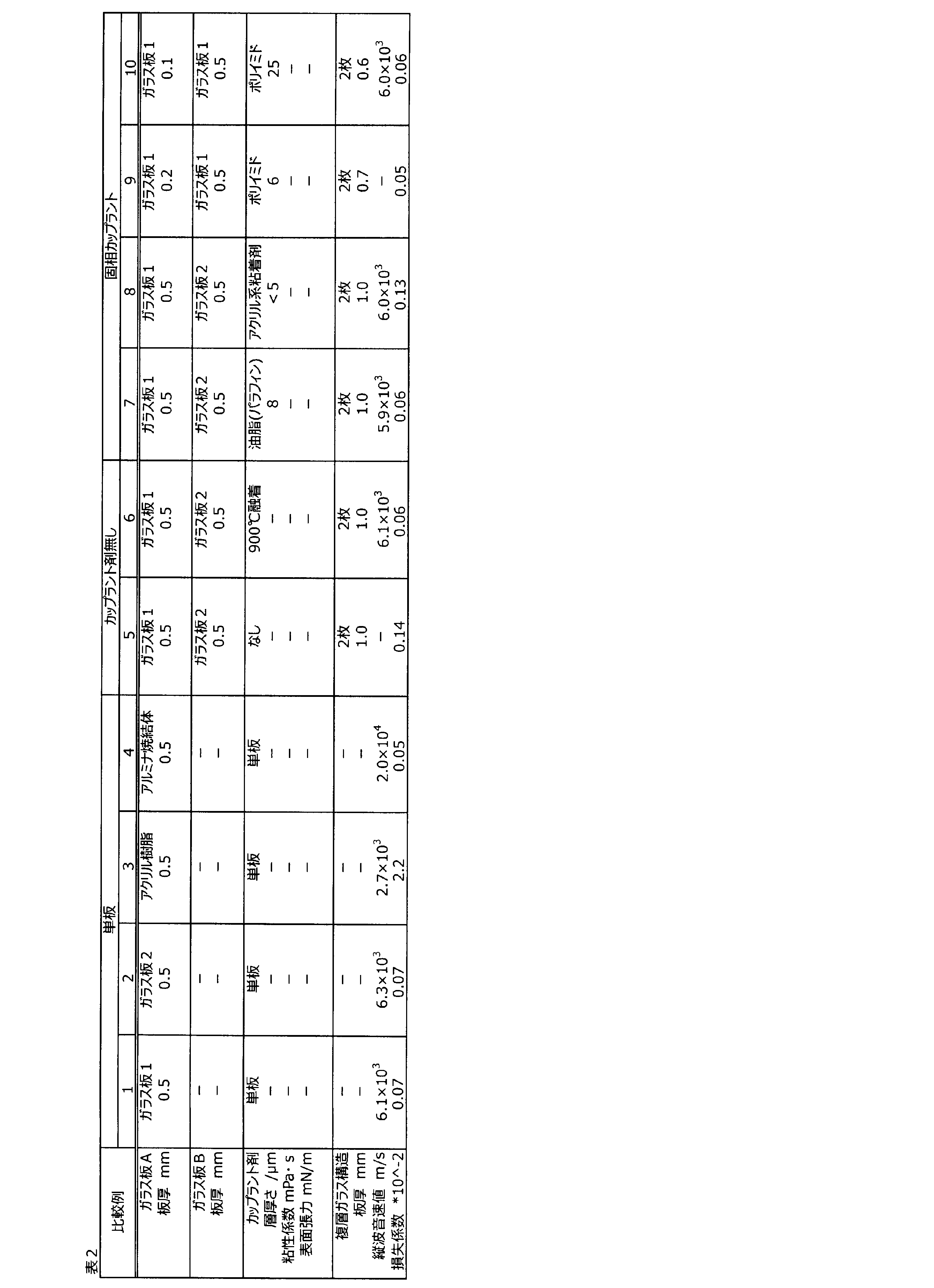
- Table 2 shows the structures and evaluation results of the glass sheet structures obtained in Comparative Examples 1 to 10, respectively.
- 10 [lambda]-2 indicated by * shows the 10-2 becomes numerical units.
- the viscosity coefficient is 0.7 mPa ⁇ s to 60 Pa ⁇ s
- the surface tension is 21 to 73 mN / m
- the thickness of the liquid layer is less than 5 ⁇ m, and 1/10 or less of the total thickness of the pair of glass plates.
- the longitudinal wave sound velocity value in the plate thickness direction is 6.0 ⁇ 10 3 m / s or more
- the loss coefficient at 25 ° C. is 1.7 ⁇ 10 ⁇ 2 or more. It was a characteristic.
- the glass plate A and the glass plate B are different types of combinations (glass plate 1 + glass plate 2), and vibration damping is better than that of the same type of combination (glass plate 1 + glass plate 1).
- the characteristics were shown (for example, see Examples 5 and 6).
- the glass plate structure according to the present invention has a large longitudinal wave sound velocity value and a large loss factor. Therefore, it can be suitably used for diaphragms used in speakers, microphones, earphones, mobile devices, etc., architectural / vehicle opening members, glass substrates for magnetic recording media, and the like.
Landscapes
- Engineering & Computer Science (AREA)
- Chemical & Material Sciences (AREA)
- Life Sciences & Earth Sciences (AREA)
- Materials Engineering (AREA)
- Signal Processing (AREA)
- Organic Chemistry (AREA)
- Physics & Mathematics (AREA)
- Acoustics & Sound (AREA)
- Multimedia (AREA)
- Chemical Kinetics & Catalysis (AREA)
- General Chemical & Material Sciences (AREA)
- Geochemistry & Mineralogy (AREA)
- Ceramic Engineering (AREA)
- Mechanical Engineering (AREA)
- Inorganic Chemistry (AREA)
- Laminated Bodies (AREA)
- Diaphragms For Electromechanical Transducers (AREA)
- Joining Of Glass To Other Materials (AREA)
- Glass Compositions (AREA)
Abstract
Description
しかし、これらは何れも材料における音速値が低いため、高周波で励振した際に、音波周波数に材料の振動が追従しにくく、分割振動が発生しやすい。そのため特に高周波数領域において所望の音圧が出にくい。
<1> 25℃における損失係数が1×10⁻²以上、かつ、板厚方向の縦波音速値が5.5×10³m/s以上である、ガラス板構成体。
<2> 2枚以上のガラス板を含み、前記ガラス板のうち少なくとも一対のガラス板の間に液体層を含む、前記<1>に記載のガラス板構成体。
<3> 前記液体層の厚みが、
前記一対のガラス板の合計の厚みが1mm以下の場合は、前記一対のガラス板の合計の厚みの1/10以下であり、
前記一対のガラス板の合計の厚みが1mm超の場合は、100μm以下である、前記<2>に記載のガラス板構成体。
<4> 前記液体層の25℃における粘性係数が1×10⁻⁴~1×10³Pa・sであり、かつ、25℃における表面張力が15~80mN/mである、前記<2>又は<3>に記載のガラス板構成体。
<5> 前記ガラス板のうち少なくとも一対のガラス板の比弾性率が共に、2.5×10⁷m2/s2以上である、前記<2>~<4>のいずれかに記載のガラス板構成体。
<6> 前記一対のガラス板を構成する2枚のガラス板のうち、一方のガラス板Aの共振周波数をQa、共振振幅の半値幅をwa、他方のガラス板Bの共振周波数をQb、共振振幅の半値幅をwbとした時に、下記[式1]の関係を満たす、前記<2>~<5>のいずれかに記載のガラス板構成体。
(wa+wb)/4<|Qa-Qb|・・・[式1]
<7> 前記一対のガラス板を構成する2枚のガラス板の質量比が0.8~1.25である、前記<2>~<6>のいずれかに記載のガラス板構成体。
<8> 前記一対のガラス板を構成する2枚のガラス板の厚みが、それぞれ0.01~15mmである、前記<2>~<7>のいずれかに記載のガラス板構成体。
<9> 前記液体層がプロピレングリコール、ジメチルシリコーンオイル、メチルフェニルシリコーンオイル、メチルハイドロジェンシリコーンオイルおよび変性シリコーンオイルからなる群より選ばれる少なくとも1種を含む前記<2>~<8>のいずれかに記載のガラス板構成体。
<10> 物理強化ガラス板および化学強化ガラス板の少なくともいずれか一方のガラス板を含む、前記<1>~<9>のいずれかに記載のガラス板構成体。
<11> 可視光透過率が60%以上である、前記<1>~<10>のいずれかに記載のガラス板構成体。
<12> 3枚以上のガラス板を含む、前記<2>~<11>のいずれかに記載のガラス板構成体。
<13> 前記ガラス板のうち少なくとも1枚、および、前記液体層の少なくともいずれか一方が着色された、前記<2>~<12>のいずれかに記載のガラス板構成体。
<14> 前記液体層に蛍光材料を含む、前記<2>~<13>のいずれかに記載のガラス板構成体。
<15> ガラス板構成体の少なくとも一方の最表面にコーティング又はフィルムが形成された、前記<1>~<14>のいずれかに記載のガラス板構成体。
<16> ガラス板構成体が曲面形状である、前記<1>~<15>のいずれかに記載のガラス板構成体。
<17> 前記液体層の屈折率と、前記一対のガラス板の屈折率との差がいずれも0.2以下である、前記<2>~<16>のいずれかに記載のガラス板構成体。
<18> ガラス板構成体の外周端面の少なくとも一部が、ガラス板構成体の振動を妨げない部材でシールされた、前記<1>~<17>のいずれかに記載のガラス板構成体。
<19> 2枚以上のガラス板を含み、前記ガラス板のうち少なくとも一対のガラス板の間に液体層を含み、
前記液体層の厚みが、
前記一対のガラス板の合計の厚みが1mm以下の場合は、前記一対のガラス板の合計の厚みの1/10以下であり、
前記一対のガラス板の合計の厚みが1mm超の場合は、100μm以下である、ガラス板構成体。
<20> 前記<1>~<19>のいずれかに記載のガラス板構成体および、前記ガラス板構成体の片面または両面に設置された少なくとも1つの振動子を含む振動板。
<21> 前記<1>~<19>のいずれかに記載のガラス板構成体または前記<20>に記載の振動板を用いた開口部材。
<22> 前記<1>~<19>のいずれかに記載のガラス板構成体を用いた磁気記録媒体用ガラス基板。
本発明に係るガラス板構成体は、25℃における損失係数が1×10⁻²以上、かつ、板厚方向の縦波音速値が5.5×10³m/s以上であることを特徴とする。なお、損失係数が大きいとは振動減衰能が大きいことを意味する。
共振を抑えるには、損失係数を大きくすればよく、すなわち、振幅hに対し相対的に周波数幅Wは大きくなり、ピークがブロードとなることを意味する。
本発明に係るガラス板構成体は、少なくとも一対のガラス板の間に流体からなる層(液体層)を設けることで、高い損失係数を実現することができる。中でも、液体層の粘性や表面張力を好適な範囲にすることで、より損失係数を高くすることができる。
これは、一対のガラス板を粘着層を介して設ける場合とは異なり、前記一対のガラス板が固着せず、各々のガラス板としての振動特性を持ち続けることに起因するものと考えられる。
液体層の25℃における表面張力は20mN/m以上がより好ましく、30mN/m以上がさらに好ましい。
液体層の表面張力はリング法などにより測定することができる。
また前記一対のガラス板の合計の厚みが1mm超の場合は、前記液体層の厚みは、100μm以下が好ましく、50μm以下がより好ましく、30μm以下がさらに好ましく、20μm以下がよりさらに好ましく、15μm以下がことさらに好ましく、10μm以下が特に好ましい。
液体層の厚みの下限は、製膜性および耐久性の点から0.01μm以上が好ましい。
化学的に安定とは、例えば光照射により変質(劣化)が少ないものであったり、少なくとも-20~70℃の温度領域で凝固、気化、分解、変色、ガラスとの化学反応等が生じないものを意味する。
より具体的には、プロピレングリコール、ジプロピレングリコール、トリプロピレングリコール、ストレートシリコーンオイル(ジメチルシリコーンオイル、メチルフェニルシリコーンオイル、メチルハイドロジェンシリコーンオイル)、変性シリコーンオイル、アクリル酸系ポリマー、液状ポリブタジエン、グリセリンペースト、フッ素系溶剤、フッ素系樹脂、アセトン、エタノール、キシレン、トルエン、水、鉱物油、およびそれらの混合物、等が挙げられる。中でも、プロピレングリコール、ジメチルシリコーンオイル、メチルフェニルシリコーンオイル、メチルハイドロジェンシリコーンオイルおよび変性シリコーンオイルからなる群より選ばれる少なくとも1種を含むことが好ましく、プロピレングリコールまたはシリコーンオイルを主成分とすることがより好ましい。
液体層における粉体の含有量は0~10体積%が好ましく、0~5体積%がより好ましい。
粉体の粒径は沈降を防ぐ観点から10nm~1μmが好ましく、0.5μm以下がより好ましい。
本発明に係るガラス板構成体(符号“10”)は、前記液体層(符号“16”)を両側から挟むように、少なくとも一対のガラス板を設けることが好ましい(図1)。一方のガラス板をガラス板A(符号“11”)、他方をガラス板B(符号“12”)とすると、ガラス板Aが共振した場合に、液体層の存在により、ガラス板Bが共振しない、又は、ガラス板Bの共振の揺れを減衰することができることから、ガラス板構成体は、ガラス板単独の場合と比べて損失係数を高くすることができる。
(wa+wb)/4<|Qa-Qb|・・・[式1]
上記[式1]における左辺の値が大きくなるほどガラス板Aとガラス板Bとの共振周波数の差異(|Qa-Qb|)が大きくなり、高い損失係数が得られるようになることから好ましい。
(wa+wb)/2<|Qa-Qb|・・・[式1’]
(wa+wb)/1<|Qa-Qb|・・・[式1”]
なお、ガラス板の共振周波数(ピークトップ)および共振振幅の半値幅は、ガラス板構成体における損失係数と同様の方法で測定することができる。
防振効果を高めた磁気記録媒体用ガラス基板用途においては、ガラス板A、ガラス板Bの板厚はそれぞれ0.3~1.2mmが好ましく、0.4~1.0mmがより好ましく、0.5~0.8mmがさらに好ましい。
なお、ガラス板の損失係数は、ガラス板構成体における損失係数と同様の方法で測定することができる。
なお、ガラス板の音速値は、ガラス板構成体における縦波音速値と同様の方法で測定することができる。
SiO2:40~80質量%、Al2O3:0~35質量%、B2O3:0~15質量%、MgO:0~20質量%、CaO:0~20質量%、SrO:0~20質量%、BaO:0~20質量%、Li2O:0~20質量%、Na2O:0~25質量%、K2O:0~20質量%、TiO2:0~10質量%、かつ、ZrO2:0~10質量%。但し上記組成がガラス全体の95質量%以上を占める。
SiO2:55~75質量%、Al2O3:0~25質量%、B2O3:0~12質量%、MgO:0~20質量%、CaO:0~20質量%、SrO:0~20質量%、BaO:0~20質量%、Li2O:0~20質量%、Na2O:0~25質量%、K2O:0~15質量%、TiO2:0~5質量%、かつ、ZrO2:0~5質量%。但し上記組成がガラス全体の95質量%以上を占める。
ガラス板A、ガラス板Bのヤング率を密度で除した値である比弾性率は、いずれも大きいほど、ガラス板の剛性を高くすることができる。具体的にはガラス板A、ガラス板Bの比弾性率がそれぞれ2.5×10⁷m2/s2以上が好ましく、2.8×107m2/s2以上がより好ましく、3.0×107m2/s2以上がさらにより好ましい。上限は特に限定されないが、4.0×107m2/s2以下であることが好ましい。
ガラス板構成体における損失係数が大きいほど振動減衰が大きくなることから好ましく、本発明に係るガラス板構成体の25℃における損失係数は1×10⁻²以上であり、好ましくは2×10⁻²以上、より好ましくは5×10⁻²以上である。
また、ガラス板構成体の板厚方向の縦波音速値は、音速が速いほど振動板とした際に高周波音の再現性が向上することから、好ましくは5.5×10³m/s以上であり、より好ましくは5.7×103m/s以上、さらにより好ましくは6.0×103m/s以上である。上限は特に限定されないが、7.0×103m/s以下が好ましい。
なお、透光性の部材としては、例えば透明スピーカー、透明マイクロフォン、建築、車両用の開口部材等の用途が挙げられる。
ガラス板の質量や厚みについても同様に、すべて異なっても、すべて同一でも、一部が異なっていてもよい。中でも、構成するガラス板の質量が全て同一であることが振動減衰性の点から好ましく用いられる。
コーティングやフィルムの厚みは、表層のガラス板の板厚の1/5以下であることが好ましい。コーティングやフィルムには従来公知の物を用いることができるが、コーティングとしては例えば撥水コーティング、親水コーティング、滑水コーティング、撥油コーティング、光反射防止コーティング、遮熱コーティング、等が挙げられる。また、フィルムとしては例えばガラス飛散防止フィルム、カラーフィルム、UVカットフィルム、IRカットフィルム、遮熱フィルム、電磁波シールドフィルム等が挙げられる。
低周波数帯域の出力音圧レベルを上げるため、ガラス板構成体にエンクロージャーまたはバッフル板を付与した構造とすることも出来る。エンクロージャーまたはバッフル板の材質は特に限定されないが、本発明のガラス板構成体を用いることが好ましい。
用いるフレームの重量は、ガラス板の重量の20%以下であることが好ましく、10%以下であることがより好ましい。
なお、ガラス板構成体とフレームとの間にはシール材(符号“31”)を有することもでき、液体層のフレームからの漏れを防止することができる。
熱可塑性樹脂(ホットメルトボンド)を用いることも出来る。例として、エチレン酢酸ビニル系、ポリオレフィン系、ポリアミド系、合成ゴム系、アクリル系、ポリウレタン系が挙げられる。
ゴムに関しては、例えば天然ゴム、合成天然ゴム、ブタジエンゴム、スチレン・ブタジエンゴム、ブチルゴム、ニトリルゴム、エチレン・プロピレンゴム、クロロプレンゴム、アクリルゴム、クロロスルホン化ポリエチレンゴム(ハイパロン)、ウレタンゴム、シリコーンゴム、フッ素ゴム、エチレン・酢酸ビニルゴム、エピクロルヒドリンゴム、多硫化ゴム(チオコール)、水素化ニトリルゴムを用いることが出来る。
シール材の厚さtは、薄すぎると十分な強度が確保されず、厚すぎると振動の支障となる。ゆえにシール材の厚さは10μm以上かつガラス構成体の合計厚みの5倍以下であることが好ましく、50μm以上かつガラス構成体の合計厚みより薄いことがより好ましい。
このガラス板構成体における好ましい態様は、上述したガラス板構成体と同様である。
本発明は、上記ガラス板構成体および振動子を含む振動板、上記ガラス板構成体を用いた開口部材、および、上記ガラス板構成体を用いた磁気記録媒体用ガラス基板にも関する。
より具体的な構成として、例えば、複層ガラスの全部または少なくとも1枚のガラス板を本発明のガラス構成体とし、制御対象の音波振動が流入する側の板の振動レベルまたはガラス間に存在する空間の音圧レベルをサンプリングし、これを制御フィルタにより適切に信号補正した上で音波振動が流出する側に設置されたガラス構成体上の振動素子に出力する構造とすることが出来る。
本振動板の用途としては、例えば電子機器用部材として、フルレンジスピーカー、15Hz~200Hz帯の低音再生用スピーカー、10kHz~100kHz帯の高音再生スピーカー、振動板の面積が0.2m2以上の大型スピーカー、振動板の面積が3cm2以下の小型スピーカー、平面型スピーカー、円筒型スピーカー、透明スピーカー、スピーカーとして機能するモバイル機器用カバーガラス、TVディスプレイ用カバーガラス、映像信号と音声信号とが同一の面から生じるディスプレイ、ウェアラブルディスプレイ用スピーカー、電光表示器、照明器具、等に利用することが出来る。また、ヘッドフォン、イヤフォンまたはマイク用の振動板、振動センサーとして用いることが出来る。
車両等の輸送機械の内装用振動部材として、車載・機載スピーカーとして用いることができる。例えばスピーカーとして機能するサイドミラー、サンバイザー、インパネ、ダッシュボード、天井、ドア、その他内装パネルとすることが出来る。これらをマイクロフォンおよびアクティブノイズコントロール用振動板として機能させることもできる。
その他の用途として、超音波発生装置用振動板、超音波モーター用スライダ、低周波発生装置、液中に音波振動を伝搬させる振動子、およびそれを用いた水槽並びに容器、振動素子、振動検出素子、振動減衰装置用のアクチュエータ用材料として用いることができる。
開口部材に適用する際には、ガラス板構成体の片面または両面に1個以上の振動素子や振動検出素子(振動子)を設置した振動板を、スピーカーやマイクロフォンとして機能させることもできる。本発明に係るガラス板構成体を用いることにより、従来再現が難しかった高周波領域の音の再生が容易に可能となる。また、ガラス板構成体の大きさ、形状、色調等における自由度が高く、意匠性を施すことが可能であることから、デザイン性にも優れた開口部材を得ることができる。また、ガラス板構成体表面または近傍に設置した集音用マイクロフォンまたは振動検出器で音声または振動をサンプリングし、これと同位相あるいは逆位相の振動をガラス板構成体に発生させることによりサンプリングした音声または振動を増幅したり打ち消したりすることができる。
より具体的には、車内スピーカー、車外スピーカー、遮音機能を有する車両用フロントガラス、サイドガラス、リアガラスまたはルーフガラスとして用いることができる。このとき、特定の音波振動のみを透過または遮断できる仕組みとしてもよい。また、音波振動により撥水性、耐着雪性、耐着氷性、防汚性を向上させた車両用窓、構造部材、化粧板として用いることもできる。具体的には、自動車用窓ガラスやミラーのほか、レンズ、センサーおよびそれらのカバーガラスとして用いることができる。
建築用開口部材としては、振動板および振動検出装置として機能する窓ガラス、ドアガラス、ルーフガラス、内装材、外装材、装飾材、構造材、外壁、遮音板および遮音壁、および太陽電池用カバーガラスとして用いることが出来る。それらを音響反射(残響)板として機能させてもよい。また、音波振動により上記の撥水性、耐着雪性、防汚性を向上させることもできる。
本発明に係るガラス板構成体は一対のガラス板の間に液体層を形成することにより得ることができる。
一対のガラス板の間に液体層を形成する方法は特に限定されず、例えば、ガラス板表面に液体層を形成し、その上に別のガラス板を設置する方法、それぞれ液体層を表面に形成したガラス板同士を貼り合わせる方法、二枚のガラス板の隙間から液体層を流し入れる方法等が挙げられる。
(ヤング率、縦波音速値、密度)
ガラス板のヤング率Eおよび音速V、およびガラス板構成体の縦波音速値Vは、長さ60mm、幅12mm、厚さ0.5mm~1mmの試験片を用い、日本工業規格(JIS-R1602-1995)に記載された超音波パルス法により25℃で測定した(オリンパス株式会社製、DL35PLUSを使用)。ガラス板構成体の縦波音速値は、板厚方向の音速を測定した。
ガラス板の密度ρはアルキメデス法(株式会社島津製作所、AUX320)により25℃で測定した。
ガラス板およびガラス板構成体の損失係数は、上記測定と同一の試験片を用い、共振法内部摩擦測定装置(日本テクノプラス株式会社、JE-HT)により25℃で計測した。具体的には試験片に600Hz~3000Hzの帯域で交流電圧を連続的に印加することによりガラス基板を曲げ1次モードで自由振動させ、その振動振幅の変化を計測した。振動振幅hが最大となる周波数を共振周波数fとした。
損失係数は、上記測定で求めた材料の共振周波数f、最大振幅より-3dB下がった点(すなわち、最大振幅-3[dB]における点)の周波数幅Wを用い、W/fで表される値を損失係数とした。
ピーク形状が非対象になるなどの理由で上記手法が適用できない試験片については、共振周波数測定において、共振状態から加振を停止した際の振動振幅の減衰時間を計測し、これを用いて損失係数を算出した。
液体層の粘性係数は回転粘度計(BROOKFIELD社、RVDV-E)を用い、25℃で計測した。
液体層の表面張力は、以下の方法により測定した。
25℃の試験液に対して平行に吊り下げた金属リングを液中に沈め、その後リングを鉛直方向に徐々に引き上げた。この時、液体膜により加えられた力のピークを測定することにより、表面張力値を算出した。
ガラス板Aとして12mm×60mm×0.5mmのガラス板1を用意し、そこに液体層としてイオン交換水を塗布し、さらにガラス板Bとして12mm×60mm×0.5mmのガラス板2を密着させ、12mm×60mm×1mmのガラス板構成体を得た。ガラス板1およびガラス板2の組成(質量%)および物性値を以下に示す。(ガラス板1)SiO2:60%、Al2O3:17%、B2O3:8%、MgO:3%、CaO:4%、SrO:8%、密度:2.5g/cm3、ヤング率:77GPa、比弾性率:3.1×107m2/s2(ガラス板2)SiO2:61.5%、Al2O3:20%、B2O3:1.5%、MgO:5.5%、CaO:4.5%、SrO:7%、密度:2.7g/cm3、ヤング率:85GPa、比弾性率:3.2×107m2/s2
液体層を変えた以外は実施例1と同様にしてガラス板構成体を得た。なお、実施例6については、ガラス板Bのガラス板2に代えてガラス板1を用いた。
ガラス板Aとしてガラス板1(比較例1)、ガラス板2(比較例2)、アクリル樹脂(比較例3)、アルミナ焼結体(比較例4)のそれぞれ単体における各種特性評価を行った。
液体層を用いずにガラス板Aにガラス板Bを密着させたガラス板構成体を得た(比較例5)。また、比較例5で得たガラス板構成体を大気雰囲気下900℃で加熱し、ガラス板Aとガラス板Bとを融着させたガラス板構成体を得た(比較例6)。
液体層に代えて各種粘着剤またはフィルムを用いてガラス板Aおよびガラス板Bを固着させたガラス板構成体をそれぞれ得た。

なお、一対のガラス板としてガラス板Aとガラス板Bとが異種の組み合わせ(ガラス板1+ガラス板2)であるものが、同種の組み合わせ(ガラス板1+ガラス板1)のものより良好な振動減衰特性を示した(例えば、実施例5および6等参照)。
カップラント剤を用いなかった場合(比較例5)、25℃における損失係数の値は1.4×10⁻³と低く、かつガラス基板間で音波を十分に伝達することができず、振動板として不適であった。ガラス板Aとガラス板Bとを900℃で融着させた場合(比較例6)、損失係数は単板と同様に低かった。
カップラント剤に固体を用い、その膜厚を25μm以下、かつ一対のガラス板の合計の厚みの1/10以下とした場合(比較例7~10)、いずれも損失係数が低く、振動板として適さなかった。
11 ガラス板A
12 ガラス板B
13 ガラス板C
16 液体層
21 コーティング
22 フィルム
30 フレーム(枠)
31 シール材
Claims (22)
- 25℃における損失係数が1×10⁻²以上、かつ、板厚方向の縦波音速値が5.5×10³m/s以上である、ガラス板構成体。
- 2枚以上のガラス板を含み、前記ガラス板のうち少なくとも一対のガラス板の間に液体層を含む、請求項1に記載のガラス板構成体。
- 前記液体層の厚みが、
前記一対のガラス板の合計の厚みが1mm以下の場合は、前記一対のガラス板の合計の厚みの1/10以下であり、
前記一対のガラス板の合計の厚みが1mm超の場合は、100μm以下である、請求項2に記載のガラス板構成体。 - 前記液体層の25℃における粘性係数が1×10⁻⁴~1×10³Pa・sであり、かつ、25℃における表面張力が15~80mN/mである、請求項2又は3に記載のガラス板構成体。
- 前記ガラス板のうち少なくとも一対のガラス板の比弾性率が共に、2.5×10⁷m2/s2以上である、請求項2~4のいずれかに記載のガラス板構成体。
- 前記一対のガラス板を構成する2枚のガラス板のうち、一方のガラス板Aの共振周波数をQa、共振振幅の半値幅をwa、他方のガラス板Bの共振周波数をQb、共振振幅の半値幅をwbとした時に、下記[式1]の関係を満たす、請求項2~5のいずれかに記載のガラス板構成体。
(wa+wb)/4<|Qa-Qb|・・・[式1] - 前記一対のガラス板を構成する2枚のガラス板の質量比が0.8~1.25である、請求項2~6のいずれかに記載のガラス板構成体。
- 前記一対のガラス板を構成する2枚のガラス板の厚みが、それぞれ0.01~15mmである、請求項2~7のいずれかに記載のガラス板構成体。
- 前記液体層がプロピレングリコール、ジメチルシリコーンオイル、メチルフェニルシリコーンオイル、メチルハイドロジェンシリコーンオイルおよび変性シリコーンオイルからなる群より選ばれる少なくとも1種を含む請求項2~8のいずれかに記載のガラス板構成体。
- 物理強化ガラス板および化学強化ガラス板の少なくともいずれか一方のガラス板を含む、請求項1~9のいずれかに記載のガラス板構成体。
- 可視光透過率が60%以上である、請求項1~10のいずれかに記載のガラス板構成体。
- 3枚以上のガラス板を含む、請求項2~11のいずれかに記載のガラス板構成体。
- 前記ガラス板のうち少なくとも1枚、および、前記液体層の少なくともいずれか一方が着色された、請求項2~12のいずれかに記載のガラス板構成体。
- 前記液体層に蛍光材料を含む、請求項2~13のいずれかに記載のガラス板構成体。
- ガラス板構成体の少なくとも一方の最表面にコーティング又はフィルムが形成された、請求項1~14のいずれかに記載のガラス板構成体。
- ガラス板構成体が曲面形状である、請求項1~15のいずれかに記載のガラス板構成体。
- 前記液体層の屈折率と、前記一対のガラス板の屈折率との差がいずれも0.2以下である、請求項2~16のいずれかに記載のガラス板構成体。
- ガラス板構成体の外周端面の少なくとも一部が、ガラス板構成体の振動を妨げない部材でシールされた、請求項1~17のいずれかに記載のガラス板構成体。
- 2枚以上のガラス板を含み、前記ガラス板のうち少なくとも一対のガラス板の間に液体層を含み、
前記液体層の厚みが、
前記一対のガラス板の合計の厚みが1mm以下の場合は、前記一対のガラス板の合計の厚みの1/10以下であり、
前記一対のガラス板の合計の厚みが1mm超の場合は、100μm以下である、ガラス板構成体。 - 請求項1~19のいずれかに記載のガラス板構成体および、前記ガラス板構成体の片面または両面に設置された少なくとも1つの振動子を含む振動板。
- 請求項1~19のいずれかに記載のガラス板構成体または請求項20に記載の振動板を用いた開口部材。
- 請求項1~19のいずれかに記載のガラス板構成体を用いた磁気記録媒体用ガラス基板。
Priority Applications (6)
| Application Number | Priority Date | Filing Date | Title |
|---|---|---|---|
| KR1020187028517A KR20180133403A (ko) | 2016-04-05 | 2017-03-31 | 유리판 구성체 |
| EP17779061.5A EP3442244B1 (en) | 2016-04-05 | 2017-03-31 | Glass sheet composite |
| CN201780021939.8A CN109076288B (zh) | 2016-04-05 | 2017-03-31 | 玻璃板结构体、振动板、开口构件以及磁记录介质用玻璃基板 |
| JP2018510578A JP6813023B2 (ja) | 2016-04-05 | 2017-03-31 | ガラス板構成体 |
| US16/151,940 US11472161B2 (en) | 2016-04-05 | 2018-10-04 | Glass sheet composite |
| US17/815,334 US20220363034A1 (en) | 2016-04-05 | 2022-07-27 | Glass sheet composite |
Applications Claiming Priority (6)
| Application Number | Priority Date | Filing Date | Title |
|---|---|---|---|
| JP2016075928 | 2016-04-05 | ||
| JP2016-075928 | 2016-04-05 | ||
| JP2016-174801 | 2016-09-07 | ||
| JP2016174801 | 2016-09-07 | ||
| JP2016-228372 | 2016-11-24 | ||
| JP2016228372 | 2016-11-24 |
Related Child Applications (1)
| Application Number | Title | Priority Date | Filing Date |
|---|---|---|---|
| US16/151,940 Continuation US11472161B2 (en) | 2016-04-05 | 2018-10-04 | Glass sheet composite |
Publications (1)
| Publication Number | Publication Date |
|---|---|
| WO2017175682A1 true WO2017175682A1 (ja) | 2017-10-12 |
Family
ID=60000439
Family Applications (1)
| Application Number | Title | Priority Date | Filing Date |
|---|---|---|---|
| PCT/JP2017/013683 WO2017175682A1 (ja) | 2016-04-05 | 2017-03-31 | ガラス板構成体 |
Country Status (6)
| Country | Link |
|---|---|
| US (2) | US11472161B2 (ja) |
| EP (1) | EP3442244B1 (ja) |
| JP (2) | JP6813023B2 (ja) |
| KR (1) | KR20180133403A (ja) |
| CN (1) | CN109076288B (ja) |
| WO (1) | WO2017175682A1 (ja) |
Cited By (8)
| Publication number | Priority date | Publication date | Assignee | Title |
|---|---|---|---|---|
| WO2018193788A1 (ja) * | 2017-04-17 | 2018-10-25 | 日本電気硝子株式会社 | ガラス樹脂複合体 |
| CN109451146A (zh) * | 2018-10-15 | 2019-03-08 | 维沃移动通信有限公司 | 一种振动处理方法及终端 |
| WO2019172076A1 (ja) * | 2018-03-06 | 2019-09-12 | Agc株式会社 | スピーカー装置 |
| JPWO2019070007A1 (ja) * | 2017-10-04 | 2020-10-22 | Agc株式会社 | ガラス板構成体及び振動板 |
| JPWO2019070004A1 (ja) * | 2017-10-04 | 2020-11-05 | Agc株式会社 | ガラス板構成体 |
| JPWO2019070006A1 (ja) * | 2017-10-04 | 2020-12-03 | Agc株式会社 | ガラス板構成体及び振動板 |
| WO2022244750A1 (ja) * | 2021-05-20 | 2022-11-24 | Agc株式会社 | ガラス板構成体及びガラス板構成体の製造方法 |
| US11632628B2 (en) * | 2017-03-29 | 2023-04-18 | AGC Inc. | Glass sheet composite |
Families Citing this family (6)
| Publication number | Priority date | Publication date | Assignee | Title |
|---|---|---|---|---|
| JP6813023B2 (ja) * | 2016-04-05 | 2021-01-13 | Agc株式会社 | ガラス板構成体 |
| JP7024551B2 (ja) * | 2017-03-29 | 2022-02-24 | Agc株式会社 | ガラス板構成体及びそれを用いた振動板並びに映像投影構造体 |
| JPWO2021060214A1 (ja) * | 2019-09-27 | 2021-04-01 | ||
| CN110784807B (zh) * | 2019-10-31 | 2021-07-06 | 歌尔股份有限公司 | 一种发声装置的振膜以及发声装置 |
| US20230249439A1 (en) * | 2020-07-10 | 2023-08-10 | Agp America S.A. | Automotive laminate with electroacoustic transducer |
| CN112829489B (zh) * | 2021-01-06 | 2021-08-24 | 常州雅得印刷有限公司 | 一种uv闪光立体烫花的包装盒印刷工艺 |
Citations (6)
| Publication number | Priority date | Publication date | Assignee | Title |
|---|---|---|---|---|
| JPH01185098A (ja) * | 1988-01-20 | 1989-07-24 | Mitsubishi Pencil Co Ltd | 疎蜜構造を有するガラス状硬質炭素質振動板の製造方法 |
| WO2014061565A1 (ja) * | 2012-10-17 | 2014-04-24 | 旭硝子株式会社 | ガラス積層体およびその製造方法、並びに、シリコーン樹脂層付き支持基材 |
| WO2014103678A1 (ja) * | 2012-12-28 | 2014-07-03 | 旭硝子株式会社 | ガラス積層体およびその製造方法、並びに、シリコーン樹脂層付き支持基材 |
| US20150086048A1 (en) * | 2013-09-20 | 2015-03-26 | Corning Incorporated | Acoustic panels and planar structures |
| JP2015065649A (ja) * | 2013-08-29 | 2015-04-09 | 日本電気硝子株式会社 | 振動板及びスピーカー |
| WO2015156395A1 (ja) * | 2014-04-10 | 2015-10-15 | 旭硝子株式会社 | ガラス積層体およびその製造方法、電子デバイスの製造方法 |
Family Cites Families (21)
| Publication number | Priority date | Publication date | Assignee | Title |
|---|---|---|---|---|
| JPS568895Y2 (ja) * | 1978-04-04 | 1981-02-26 | ||
| FR2447273A1 (fr) * | 1979-01-23 | 1980-08-22 | Brinks France Sa | Vitrage composite a haute resistance aux impacts |
| JPS5643994U (ja) * | 1979-09-13 | 1981-04-21 | ||
| JPH0211131U (ja) | 1988-06-30 | 1990-01-24 | ||
| JPH06255016A (ja) * | 1993-03-01 | 1994-09-13 | Afuiniteii Kk | 自律応答積層体と製法及びそれを使用した窓 |
| JPH0952738A (ja) | 1995-08-17 | 1997-02-25 | Asahi Glass Co Ltd | 熱線遮断性ガラス |
| JPWO2002053369A1 (ja) | 2000-12-28 | 2004-04-30 | 旭硝子株式会社 | 防汚性透明積層体とその製造方法、照明装置用透光性カバーおよび照明装置 |
| WO2004039738A1 (ja) * | 2002-10-29 | 2004-05-13 | Hoya Corporation | 化学強化用ガラス、情報記録媒体用基板、情報記録媒体及び情報記録媒体の製造方法 |
| ES2297255T3 (es) * | 2003-05-22 | 2008-05-01 | Affinity Co., Ltd. | Estratificado que regula la luz de manera autonoma y ventana que lo utiliza. |
| KR100790732B1 (ko) | 2006-02-15 | 2008-01-02 | 삼성전기주식회사 | 신뢰성이 확보된 액체 렌즈용 절연액 및 그 절연액을사용한 액체 렌즈 |
| US8189851B2 (en) * | 2009-03-06 | 2012-05-29 | Emo Labs, Inc. | Optically clear diaphragm for an acoustic transducer and method for making same |
| KR102043438B1 (ko) * | 2012-06-01 | 2019-11-11 | 코닝 인코포레이티드 | 최적화된 파손 성능을 위한 유리 적층 구조 |
| WO2014088939A1 (en) * | 2012-12-06 | 2014-06-12 | 3M Innovative Properties Company | Discrete coating of liquid on a liquid-coated substrate and use in forming laminates |
| JP6371978B2 (ja) * | 2012-12-14 | 2018-08-15 | パナソニックIpマネジメント株式会社 | 振動板と、これを用いたラウドスピーカと、ラウドスピーカを用いた電子機器、ならびに移動体装置 |
| JP6447510B2 (ja) | 2013-11-28 | 2019-01-09 | Agc株式会社 | 無アルカリガラス基板、および、無アルカリガラス基板の薄板化方法 |
| JP6372795B2 (ja) | 2014-03-18 | 2018-08-15 | 淳一 櫛引 | 強化ガラスの表面特性の測定方法 |
| JP6813023B2 (ja) * | 2016-04-05 | 2021-01-13 | Agc株式会社 | ガラス板構成体 |
| JPWO2018155518A1 (ja) * | 2017-02-23 | 2019-12-19 | Agc株式会社 | ガラス板構成体 |
| WO2018181626A1 (ja) * | 2017-03-29 | 2018-10-04 | Agc株式会社 | ガラス板構成体 |
| JP7024551B2 (ja) * | 2017-03-29 | 2022-02-24 | Agc株式会社 | ガラス板構成体及びそれを用いた振動板並びに映像投影構造体 |
| JP7092143B2 (ja) * | 2017-10-04 | 2022-06-28 | Agc株式会社 | ガラス板構成体及び振動板 |
-
2017
- 2017-03-31 JP JP2018510578A patent/JP6813023B2/ja active Active
- 2017-03-31 EP EP17779061.5A patent/EP3442244B1/en active Active
- 2017-03-31 KR KR1020187028517A patent/KR20180133403A/ko unknown
- 2017-03-31 WO PCT/JP2017/013683 patent/WO2017175682A1/ja active Application Filing
- 2017-03-31 CN CN201780021939.8A patent/CN109076288B/zh active Active
-
2018
- 2018-10-04 US US16/151,940 patent/US11472161B2/en active Active
-
2020
- 2020-12-11 JP JP2020206024A patent/JP7067601B2/ja active Active
-
2022
- 2022-07-27 US US17/815,334 patent/US20220363034A1/en active Pending
Patent Citations (6)
| Publication number | Priority date | Publication date | Assignee | Title |
|---|---|---|---|---|
| JPH01185098A (ja) * | 1988-01-20 | 1989-07-24 | Mitsubishi Pencil Co Ltd | 疎蜜構造を有するガラス状硬質炭素質振動板の製造方法 |
| WO2014061565A1 (ja) * | 2012-10-17 | 2014-04-24 | 旭硝子株式会社 | ガラス積層体およびその製造方法、並びに、シリコーン樹脂層付き支持基材 |
| WO2014103678A1 (ja) * | 2012-12-28 | 2014-07-03 | 旭硝子株式会社 | ガラス積層体およびその製造方法、並びに、シリコーン樹脂層付き支持基材 |
| JP2015065649A (ja) * | 2013-08-29 | 2015-04-09 | 日本電気硝子株式会社 | 振動板及びスピーカー |
| US20150086048A1 (en) * | 2013-09-20 | 2015-03-26 | Corning Incorporated | Acoustic panels and planar structures |
| WO2015156395A1 (ja) * | 2014-04-10 | 2015-10-15 | 旭硝子株式会社 | ガラス積層体およびその製造方法、電子デバイスの製造方法 |
Non-Patent Citations (2)
| Title |
|---|
| OLIVIER MAL: "A Novel Glass Laminated Structure for Flat Panel Loudspeakers", AES CONVENTION, vol. 124, pages 7343 |
| See also references of EP3442244A4 |
Cited By (19)
| Publication number | Priority date | Publication date | Assignee | Title |
|---|---|---|---|---|
| US11632628B2 (en) * | 2017-03-29 | 2023-04-18 | AGC Inc. | Glass sheet composite |
| US11485113B2 (en) | 2017-04-17 | 2022-11-01 | Nippon Electric Glass Co., Ltd. | Glass-resin composite |
| WO2018193788A1 (ja) * | 2017-04-17 | 2018-10-25 | 日本電気硝子株式会社 | ガラス樹脂複合体 |
| JP7092142B2 (ja) | 2017-10-04 | 2022-06-28 | Agc株式会社 | ガラス板構成体及び振動板 |
| JPWO2019070007A1 (ja) * | 2017-10-04 | 2020-10-22 | Agc株式会社 | ガラス板構成体及び振動板 |
| JPWO2019070004A1 (ja) * | 2017-10-04 | 2020-11-05 | Agc株式会社 | ガラス板構成体 |
| JPWO2019070006A1 (ja) * | 2017-10-04 | 2020-12-03 | Agc株式会社 | ガラス板構成体及び振動板 |
| US11420421B2 (en) * | 2017-10-04 | 2022-08-23 | AGC Inc. | Glass sheet composite, and diaphragm |
| JP7092141B2 (ja) | 2017-10-04 | 2022-06-28 | Agc株式会社 | ガラス板構成体 |
| JP7092143B2 (ja) | 2017-10-04 | 2022-06-28 | Agc株式会社 | ガラス板構成体及び振動板 |
| CN111819865A (zh) * | 2018-03-06 | 2020-10-23 | Agc株式会社 | 扬声器装置 |
| CN111819865B (zh) * | 2018-03-06 | 2022-06-14 | Agc株式会社 | 扬声器装置 |
| US11290807B2 (en) | 2018-03-06 | 2022-03-29 | AGC Inc. | Speaker device |
| JPWO2019172076A1 (ja) * | 2018-03-06 | 2021-03-04 | Agc株式会社 | スピーカー装置 |
| WO2019172076A1 (ja) * | 2018-03-06 | 2019-09-12 | Agc株式会社 | スピーカー装置 |
| JP7314928B2 (ja) | 2018-03-06 | 2023-07-26 | Agc株式会社 | スピーカー装置 |
| CN109451146A (zh) * | 2018-10-15 | 2019-03-08 | 维沃移动通信有限公司 | 一种振动处理方法及终端 |
| WO2022244750A1 (ja) * | 2021-05-20 | 2022-11-24 | Agc株式会社 | ガラス板構成体及びガラス板構成体の製造方法 |
| DE112022002692T5 (de) | 2021-05-20 | 2024-03-07 | AGC Inc. | Glasplattenstrukturkörper und glasplattenstrukturkörperherstellungsverfahren |
Also Published As
| Publication number | Publication date |
|---|---|
| US20220363034A1 (en) | 2022-11-17 |
| CN109076288A (zh) | 2018-12-21 |
| CN109076288B (zh) | 2020-09-22 |
| JPWO2017175682A1 (ja) | 2019-02-28 |
| US11472161B2 (en) | 2022-10-18 |
| EP3442244A4 (en) | 2019-07-24 |
| JP7067601B2 (ja) | 2022-05-16 |
| JP6813023B2 (ja) | 2021-01-13 |
| JP2021061614A (ja) | 2021-04-15 |
| US20190030862A1 (en) | 2019-01-31 |
| EP3442244A1 (en) | 2019-02-13 |
| EP3442244B1 (en) | 2020-04-15 |
| KR20180133403A (ko) | 2018-12-14 |
Similar Documents
| Publication | Publication Date | Title |
|---|---|---|
| JP7067601B2 (ja) | 透光性の開口部材 | |
| WO2019172076A1 (ja) | スピーカー装置 | |
| JP7231071B2 (ja) | 振動板 | |
| JP2019068368A (ja) | ガラス振動板構成体及び開口部材 | |
| WO2021060214A1 (ja) | 振動装置 | |
| US11632628B2 (en) | Glass sheet composite | |
| US20200230922A1 (en) | Glass sheet composite | |
| WO2019070007A1 (ja) | ガラス板構成体及び振動板 | |
| WO2022045027A1 (ja) | ガラス板構成体、振動板および開口部材 | |
| US11385678B2 (en) | Display device and television device | |
| CN111183656B (zh) | 玻璃板结构体和振动板 | |
| JPWO2020137978A1 (ja) | 振動装置 |
Legal Events
| Date | Code | Title | Description |
|---|---|---|---|
| WWE | Wipo information: entry into national phase |
Ref document number: 2018510578 Country of ref document: JP |
|
| ENP | Entry into the national phase |
Ref document number: 20187028517 Country of ref document: KR Kind code of ref document: A |
|
| NENP | Non-entry into the national phase |
Ref country code: DE |
|
| WWE | Wipo information: entry into national phase |
Ref document number: 2017779061 Country of ref document: EP |
|
| ENP | Entry into the national phase |
Ref document number: 2017779061 Country of ref document: EP Effective date: 20181105 |
|
| 121 | Ep: the epo has been informed by wipo that ep was designated in this application |
Ref document number: 17779061 Country of ref document: EP Kind code of ref document: A1 |