WO2017175601A1 - 熱電発電装置 - Google Patents
熱電発電装置 Download PDFInfo
- Publication number
- WO2017175601A1 WO2017175601A1 PCT/JP2017/011947 JP2017011947W WO2017175601A1 WO 2017175601 A1 WO2017175601 A1 WO 2017175601A1 JP 2017011947 W JP2017011947 W JP 2017011947W WO 2017175601 A1 WO2017175601 A1 WO 2017175601A1
- Authority
- WO
- WIPO (PCT)
- Prior art keywords
- holding member
- power generation
- fin
- generation module
- fluid
- Prior art date
- Legal status (The legal status is an assumption and is not a legal conclusion. Google has not performed a legal analysis and makes no representation as to the accuracy of the status listed.)
- Ceased
Links
Images





Classifications
-
- F—MECHANICAL ENGINEERING; LIGHTING; HEATING; WEAPONS; BLASTING
- F28—HEAT EXCHANGE IN GENERAL
- F28F—DETAILS OF HEAT-EXCHANGE AND HEAT-TRANSFER APPARATUS, OF GENERAL APPLICATION
- F28F3/00—Plate-like or laminated elements; Assemblies of plate-like or laminated elements
- F28F3/02—Elements or assemblies thereof with means for increasing heat-transfer area, e.g. with fins, with recesses, with corrugations
- F28F3/025—Elements or assemblies thereof with means for increasing heat-transfer area, e.g. with fins, with recesses, with corrugations the means being corrugated, plate-like elements
-
- F—MECHANICAL ENGINEERING; LIGHTING; HEATING; WEAPONS; BLASTING
- F28—HEAT EXCHANGE IN GENERAL
- F28F—DETAILS OF HEAT-EXCHANGE AND HEAT-TRANSFER APPARATUS, OF GENERAL APPLICATION
- F28F3/00—Plate-like or laminated elements; Assemblies of plate-like or laminated elements
- F28F3/02—Elements or assemblies thereof with means for increasing heat-transfer area, e.g. with fins, with recesses, with corrugations
- F28F3/025—Elements or assemblies thereof with means for increasing heat-transfer area, e.g. with fins, with recesses, with corrugations the means being corrugated, plate-like elements
- F28F3/027—Elements or assemblies thereof with means for increasing heat-transfer area, e.g. with fins, with recesses, with corrugations the means being corrugated, plate-like elements with openings, e.g. louvered corrugated fins; Assemblies of corrugated strips
-
- H—ELECTRICITY
- H02—GENERATION; CONVERSION OR DISTRIBUTION OF ELECTRIC POWER
- H02N—ELECTRIC MACHINES NOT OTHERWISE PROVIDED FOR
- H02N11/00—Generators or motors not provided for elsewhere; Alleged perpetua mobilia obtained by electric or magnetic means
-
- H—ELECTRICITY
- H10—SEMICONDUCTOR DEVICES; ELECTRIC SOLID-STATE DEVICES NOT OTHERWISE PROVIDED FOR
- H10N—ELECTRIC SOLID-STATE DEVICES NOT OTHERWISE PROVIDED FOR
- H10N10/00—Thermoelectric devices comprising a junction of dissimilar materials, i.e. devices exhibiting Seebeck or Peltier effects
- H10N10/10—Thermoelectric devices comprising a junction of dissimilar materials, i.e. devices exhibiting Seebeck or Peltier effects operating with only the Peltier or Seebeck effects
- H10N10/13—Thermoelectric devices comprising a junction of dissimilar materials, i.e. devices exhibiting Seebeck or Peltier effects operating with only the Peltier or Seebeck effects characterised by the heat-exchanging means at the junction
-
- H—ELECTRICITY
- H10—SEMICONDUCTOR DEVICES; ELECTRIC SOLID-STATE DEVICES NOT OTHERWISE PROVIDED FOR
- H10N—ELECTRIC SOLID-STATE DEVICES NOT OTHERWISE PROVIDED FOR
- H10N10/00—Thermoelectric devices comprising a junction of dissimilar materials, i.e. devices exhibiting Seebeck or Peltier effects
- H10N10/10—Thermoelectric devices comprising a junction of dissimilar materials, i.e. devices exhibiting Seebeck or Peltier effects operating with only the Peltier or Seebeck effects
- H10N10/17—Thermoelectric devices comprising a junction of dissimilar materials, i.e. devices exhibiting Seebeck or Peltier effects operating with only the Peltier or Seebeck effects characterised by the structure or configuration of the cell or thermocouple forming the device
-
- H—ELECTRICITY
- H10—SEMICONDUCTOR DEVICES; ELECTRIC SOLID-STATE DEVICES NOT OTHERWISE PROVIDED FOR
- H10W—GENERIC PACKAGES, INTERCONNECTIONS, CONNECTORS OR OTHER CONSTRUCTIONAL DETAILS OF DEVICES COVERED BY CLASS H10
- H10W40/00—Arrangements for thermal protection or thermal control
- H10W40/40—Arrangements for thermal protection or thermal control involving heat exchange by flowing fluids
- H10W40/43—Arrangements for thermal protection or thermal control involving heat exchange by flowing fluids by flowing gases, e.g. forced air cooling
-
- H—ELECTRICITY
- H10—SEMICONDUCTOR DEVICES; ELECTRIC SOLID-STATE DEVICES NOT OTHERWISE PROVIDED FOR
- H10W—GENERIC PACKAGES, INTERCONNECTIONS, CONNECTORS OR OTHER CONSTRUCTIONAL DETAILS OF DEVICES COVERED BY CLASS H10
- H10W40/00—Arrangements for thermal protection or thermal control
- H10W40/40—Arrangements for thermal protection or thermal control involving heat exchange by flowing fluids
- H10W40/47—Arrangements for thermal protection or thermal control involving heat exchange by flowing fluids by flowing liquids, e.g. forced water cooling
-
- H—ELECTRICITY
- H10—SEMICONDUCTOR DEVICES; ELECTRIC SOLID-STATE DEVICES NOT OTHERWISE PROVIDED FOR
- H10W—GENERIC PACKAGES, INTERCONNECTIONS, CONNECTORS OR OTHER CONSTRUCTIONAL DETAILS OF DEVICES COVERED BY CLASS H10
- H10W76/00—Containers; Fillings or auxiliary members therefor; Seals
- H10W76/60—Seals
-
- H—ELECTRICITY
- H10—SEMICONDUCTOR DEVICES; ELECTRIC SOLID-STATE DEVICES NOT OTHERWISE PROVIDED FOR
- H10W—GENERIC PACKAGES, INTERCONNECTIONS, CONNECTORS OR OTHER CONSTRUCTIONAL DETAILS OF DEVICES COVERED BY CLASS H10
- H10W90/00—Package configurations
-
- F—MECHANICAL ENGINEERING; LIGHTING; HEATING; WEAPONS; BLASTING
- F28—HEAT EXCHANGE IN GENERAL
- F28F—DETAILS OF HEAT-EXCHANGE AND HEAT-TRANSFER APPARATUS, OF GENERAL APPLICATION
- F28F2215/00—Fins
- F28F2215/04—Assemblies of fins having different features, e.g. with different fin densities
-
- F—MECHANICAL ENGINEERING; LIGHTING; HEATING; WEAPONS; BLASTING
- F28—HEAT EXCHANGE IN GENERAL
- F28F—DETAILS OF HEAT-EXCHANGE AND HEAT-TRANSFER APPARATUS, OF GENERAL APPLICATION
- F28F2215/00—Fins
- F28F2215/08—Fins with openings, e.g. louvers
Definitions
- thermoelectric generator that converts thermal energy into electric energy by the Seebeck effect.
- the thermoelectric generator of Patent Document 1 has a casing for housing a thermoelectric conversion element.
- This casing consists of an upper case and a lower case.
- the upper case and the lower case form a casing by welding the flange portions formed on the outer edge portion with the thermoelectric conversion element sandwiched therebetween.
- the lower case is formed with a flat contact surface that contacts the thermoelectric conversion element via the high temperature side insulating member and a rib that protrudes so as to surround the periphery of the contact surface.
- the upper case is formed with a flat contact surface that contacts the thermoelectric conversion element via the low-temperature side insulating member and a rib that protrudes so as to surround the periphery of the contact surface.
- Patent Document 1 increases the rigidity by ribs provided in each case so as to surround the periphery of the contact surface of the upper case or the lower case that contacts the thermoelectric conversion element. Ensuring the adhesiveness between each case and the thermoelectric conversion element is ensured.
- the external force does not act on the entire case but acts directly so that the portion constituting the contact surface bends, the portion itself is not strong enough and is easily bent. In this way, when an external force that is difficult to enjoy the effect of improving the rigidity due to the ribs is applied, the contact surface pressure between the case and the thermoelectric conversion element is greatly biased by the deflection, and the adhesion between the case and the thermoelectric conversion element is reduced. It may be damaged.
- an object of the disclosure in this specification is to provide a thermoelectric power generation device that achieves uniform contact surface pressure between a holding member that holds a thermoelectric conversion element and the thermoelectric conversion element.
- the thermoelectric generator according to the first aspect of the present disclosure includes a pipe through which the first fluid flows, a power generation module, a holding member, and a heat exchange fin.
- the power generation module has a thermoelectric conversion element inside and is provided by being stacked on a tube.
- the holding member has a holding force for holding the power generation module and the tube so as to be capable of heat transfer in a state where both outer portions located outside both ends of the laminated body formed by stacking the power generation module and the tube are fixed. provide.
- the heat exchange fin is provided on the surface of the holding member opposite to the surface in contact with the power generation module, and contacts the second fluid having a higher temperature than the first fluid.
- the heat exchange fin is provided between a pair of end fin portions provided on the opposite surface of the holding member with respect to both end portions of the laminate, and an end fin portion provided between the end fin portion and the end fin portion. And an intermediate fin portion having higher rigidity.
- the holding member provides a holding force for holding the laminate so that it can be moved by heat in a state where both outer portions located outside both ends of the laminate of the power generation module and the tube are fixed. .
- the contact surface pressure between the holding member and the power generation module is larger at both ends of the laminate than at the center. Then, the contact surface pressure between the holding member and the power generation module becomes non-uniform as a whole, which may cause the holding member to lift, and adversely affect the heat transfer performance between the holding member and the power generation module.
- the fin for heat exchange is configured so that the rigidity of the intermediate fin portion at the center portion is higher than the end fin portion provided at the both end portions side of the holding member.
- transformation of a holding member can be suppressed in the location corresponded to.
- the holding member further utilizes the heat exchange fins to make contact surface pressure with the power generation module in the center portion and the power generation modules on both end sides. The difference from the contact surface pressure can be suppressed. Therefore, it is possible to provide a thermoelectric generator that can achieve uniform contact surface pressure between the holding member that holds the thermoelectric conversion element and the thermoelectric conversion element, and can prevent the holding member from being lifted.
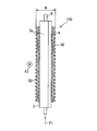
- thermoelectric power generator of a 1st embodiment of this indication. It is a front view which shows the thermoelectric generator of this indication. It is a top view which shows the thermoelectric power generator seen in the arrow III direction of FIG.
- FIG. 4 is a side view showing the thermoelectric generator as viewed in the direction of arrow IV in FIG. 3. It is a figure which shows the intermediate
- thermoelectric generator 100 as one form is disclosed in 1st Embodiment. A first embodiment will be described with reference to FIGS.
- the thermoelectric power generation apparatus 100 is an apparatus that can generate heat by converting thermal energy into electric power energy by the Seebeck effect.
- a temperature difference is given between one side and the other side of a power generation module having a thermoelectric conversion element, the thermoelectric power generation apparatus 100 generates power using a phenomenon in which a potential difference occurs and electrons flow.
- a temperature difference is given to both sides of the power generation module using the first fluid having a low temperature and the second fluid having a higher temperature than the first fluid. Any fluid capable of giving a temperature difference can be adopted as the first fluid and the second fluid.
- the first fluid may be referred to as a low-temperature fluid
- the second fluid may be referred to as a high-temperature fluid that is hotter than the low-temperature fluid.
- the thermoelectric generator 100 includes a first passage through which a high-temperature fluid flows, a second passage through which a low-temperature fluid flows, and a power generation module 1 that is provided so as to be capable of transferring heat to the high-temperature fluid on one side and the low-temperature fluid on the other side.
- the thermoelectric power generation apparatus 100 further includes a first holding member 3 and a second holding member 4 that enhance the adhesion between the members so as to ensure heat transfer between the low-temperature fluid and the high-temperature fluid and the power generation module 1.
- the first holding member 3 and the second holding member 4 are also referred to as holding members 3 and 4 below.
- Each power generation module 1 has a thermoelectric conversion element.
- a plurality of thermoelectric conversion elements are accommodated in a case which is a flat box. Inside the power generation module 1, a plurality of thermoelectric conversion elements are installed side by side in the flow direction F2 of the high-temperature fluid.
- the inside of the case is, for example, in a vacuum state or filled with an inert gas.
- This case is also an airtight case that seals the internal space.
- the case is made of, for example, a stainless material.
- the thermoelectric conversion element is configured by connecting alternately P-type semiconductor elements and N-type semiconductor elements in a mesh pattern.
- a high temperature fluid or a high temperature portion capable of transferring heat with a high temperature fluid is brought into contact with one surface, and a low temperature portion capable of transferring heat with a low temperature fluid or a low temperature fluid is brought into contact with the other surface.
- a temperature difference is generated between one side and the other side of the battery, and power is generated by movement of electrons caused by the potential difference.
- thermoelectric generator 100 one surface of the power generation module 1 located on one side is in contact with the first holding member 3 constituting the high temperature part, and the other surface is in contact with the tube 6 constituting the low temperature part.
- One surface of the power generation module 1 located on the other side in the thermoelectric generator 100 is in contact with the pipe 6 constituting the low temperature part, and the other surface is in contact with the second holding member 4 constituting the high temperature part.
- the holding members 3 and 4 can be formed, for example, by processing a plate-like member.
- 1st holding member 3 and 2nd holding member 4 are formed in the shape where both ends can be welded mutually.
- This shape can be formed by casting or bending.
- the first holding member 3 has joint portions 3a positioned on the distal end side with respect to the right-angled curved portion at both ends, and the second holding member 4 is located on the distal end side with respect to the right-angled curved portion. It has the junction part 4a located in each of both ends.
- the joint portion 3a and the joint portion 4a form an overlapping portion extending in a direction parallel to the flow direction F1 of the low-temperature fluid flowing inside the pipe 6.
- the overlapping portions are welded to each other by, for example, seam welding or laser welding.
- the joint portion 3a and the joint portion 4a correspond to both outer side portions located outside the holding members 3 and 4 with respect to both end portions in the laminated body in which the power generation module 1 and the pipe 6 are integrally stacked.
- the 1st holding member 3 and the 2nd holding member 4 provide the holding force which hold
- the compression force is a force acting in the direction indicated by the white arrow in FIG.
- the joint portion 3a and the joint portion 4a may be disposed outside the laminate in the longitudinal direction of the cross section of the tube 6.
- the cross-sectional longitudinal direction of the tube 6 may be the width direction of the tube 6.
- the tube 6 and the power generation module 1 are held by the above-described compression force, and do not have a structure that is individually fixed to the first holding member 3 or the second holding member 4. That is, the tube 6 and the power generation module 1 can be displaced in the high-temperature fluid flow direction F ⁇ b> 2 with respect to the first holding member 3 and the second holding member 4 in accordance with the expansion and contraction of each member. Therefore, even if each member expands or contracts due to a temperature difference caused by the high temperature fluid and the low temperature fluid, the pipe 6 and the power generation module 1 can be displaced. The thermal expansion difference can be absorbed.
- An internal space that is a space surrounded by the first holding member 3 and the second holding member 4 is formed by joining the first holding member 3 and the second holding member 4 accompanying the welding.
- two power generation modules 1 and a pipe 6 are accommodated.
- the tube 6 is made of stainless steel or aluminum, for example, and has a second passage that is divided into a plurality of internal passages through which a low-temperature fluid flows.
- the pipe 6 has the same length as that of the power generation module 1 in the flow direction F2, and has a size that is equal to or greater than that of the power generation module 1 in the flow direction F1.
- the first holding member 3 is provided with heat exchange fins 5 on the surface opposite to the surface in contact with the power generation module 1.
- the second holding member 4 is provided with heat exchange fins 5 on the surface opposite to the surface in contact with the power generation module 1.
- the heat exchange fin 5 is provided in a first passage through which a high-temperature fluid that contacts the heat exchange fin 5 flows.
- the thermoelectric generator 100 is composed of two power generation modules 1 having a flat tube 6 with outer surfaces through which a low-temperature fluid flows and a thermoelectric conversion element in contact with the outer surface of the tube 6 so as to sandwich the tube 6 therebetween. And comprising.
- the first holding member 3 is formed of an iron plate or a stainless steel plate, and is in contact with the surface located on the opposite side to the tube 6 in one power generation module 1.
- the second holding member 4 is formed of an iron plate or a stainless steel plate, and is in contact with the surface located on the opposite side to the tube 6 in the other power generation module 1.
- a heat exchange fin 5 made of stainless steel or aluminum is joined to the surface of the first holding member 3 opposite to the power generation module 1 by brazing or the like.
- a heat exchange fin 5 made of stainless steel or aluminum is joined to the surface of the second holding member 4 opposite to the power generation module 1 by brazing or the like.
- the heat exchange fin 5 includes an end-side fin portion 50 and an intermediate fin portion 51. Both the end-side fin portion 50 and the intermediate fin portion 51 have an effect of promoting heat transfer in order to enhance heat exchange between the heat transmitted to the first holding member 3 and the second holding member 4 and the high-temperature fluid flowing therearound. It is a member.
- the intermediate fin portion 51 is configured by a shape or material having higher rigidity than the end fin portion 50. Further, when the intermediate fin portion 51 has the same shape as the end fin portion 50, the intermediate fin portion 51 may be configured with a plate thickness that is higher in rigidity than the end fin portion 50.
- the end fin portion 50 is a part of the heat exchange fin 5 illustrated by a two-dot chain line in FIG.
- the intermediate fin portion 51 is a part of the heat exchange fin 5 illustrated by a broken line in FIG. 2 and 3, the specific shape of the intermediate fin portion 51 is omitted.
- the end fin portion 50 is provided on the surface on the opposite side with respect to the portions of the holding members 3 and 4 facing both end portions of the laminate sandwiched between the first holding member 3 and the second holding member 4.
- a pair of the end-side fin portions 50 are provided so as to occupy a predetermined range at both ends of the width along the direction F2 in the heat exchange fin 5.
- the end side fin part 50 is provided in the range which occupies the length equivalent to the electric power generation module 1 about the flow direction F1.
- the intermediate fin portion 51 is provided so as to occupy between the pair of end-side fin portions 50 provided on both ends of the heat exchange fin 5.
- each of the first holding member 3 and the second holding member 4 is fixed in a state where a force is applied in the direction indicated by the white arrow in FIG. For this reason, the bending stress which brings about the deformation
- the second holding member 4 is subjected to a bending stress that causes deformation such that the central portion protrudes downward with respect to the joint portion 4a side. Therefore, according to the study by the inventors, the contact surface pressure between the power generation module 1 and the holding member is larger at the both ends of the laminate than at the center, so that a large deviation occurs in the contact surface pressure between the two. In some cases, heat transferability between the holding member and the thermoelectric conversion element is impaired.
- thermoelectric generator 100 is configured so that the rigidity of the intermediate fin portion 51 in the heat exchange fin 5 is higher than that of the end fin portions 50 on both ends, the central portion of each holding member 3, 4 is the aforementioned. Strong against bending stress. Thereby, about each holding member 3 and 4, the deformation
- the intermediate fin portion 51 is configured by a straight fin in which a cross-sectional shape perpendicular to the direction F2 is formed in a wave shape so as to have a plate portion continuously extending along the direction F2.
- the plate portions of the intermediate fin portion 51 are arranged so as to be aligned in a direction perpendicular to the direction F2, and continuously extend along the direction F2 over the entire width of the direction F2 in the intermediate fin portion 51.
- the straight fin has a fin shape in which a crest or a trough extends continuously along the direction F2 in the same manner as the plate described above.
- the straight fins are formed in a corrugated shape by bending a flat plate having a predetermined length necessary for the intermediate fin portion 51 in the direction F2 so as to have a predetermined length necessary for the intermediate fin portion 51 in a direction perpendicular to the direction F2. Can be produced.
- the straight fins manufactured in this way are joined to the predetermined positions of the first holding member 3 and the second holding member 4 to exhibit the above-described function as the intermediate fin portion 51.
- the intermediate fin portion 51 has rigidity characteristics such that the rigidity is weak in the wave traveling direction and the rigidity is increased in the direction in which the plate portion extends.
- the rigidity of the holding members 3 and 4 can be enhanced. As a result, a decrease in contact surface pressure or a gap is generated between the central portion of the first holding member 3 and the power generation module 1 or between the central portion of the second holding member 4 and the power generation module 1. It becomes difficult.
- the end side fin part 50 is comprised by the offset fin, for example.
- the offset fins are fins that are arranged so that the corrugated fins adjacent to each other in the first direction are displaced along the direction perpendicular to the first direction.
- the offset fins are fins in which corrugated fins adjacent in the first direction are arranged in a staggered manner along a direction perpendicular to the first direction.
- the first direction is the direction F2 in which the high-temperature fluid flows will be described as an example.
- the first direction may be a direction that intersects the direction F2.
- the first direction is a direction (F2 direction in the drawing) in which a line segment connecting the joint portions at both ends of each holding member 3 and 4 extends.
- the end side fin part 50 has a plurality of corrugated parts in which the crests 50a and the troughs 50b are alternately arranged along the direction perpendicular to the first direction.
- the end side fin part 50 comprises the offset fin provided so that the adjacent peak part 50a and adjacent valley part 50b may be offset along the direction perpendicular
- the offset fin can be manufactured by putting a plate material made of aluminum, aluminum alloy or the like into a molding apparatus and performing slit processing or press molding processing.
- the offset fins have a shape that is shifted by a fixed interval in the direction perpendicular to the ventilation direction when the bent portion adjacent to the ventilation direction rises. For example, as illustrated in FIG. 6, the rising of the bent portion adjacent in the ventilation direction has a shape shifted by a half width in a direction orthogonal to the ventilation direction. Therefore, since the offset fin forms a fin that is divided in the ventilation direction, it is possible to promote the generation of a turbulent flow of ventilation and improve heat transfer between the fin and the high-temperature fluid.
- the end side fin part 50 has a characteristic that the rigidity is weaker than the intermediate fin part 51 in the direction in which adjacent peak parts 50a and valley parts 50b are arranged in an offset arrangement, that is, in the first direction. This is because, in the end-side fin portion 50, the crest portion 50 a and the trough portion 50 b arranged along the first direction are continuously formed along the first direction like the intermediate fin portion 51. This is because the fins are divided so as to be lined up at positions shifted by about a half width.
- each holding member 3, 4 is integrated with the intermediate fin portion 51 at a portion integrated with the end-side fin portion 50.
- the rigidity becomes lower than that of the part.
- each of the holding members 3 and 4 is less likely to bend due to the portion integrated with the end fin portion 50 being easily bent, and can suppress a decrease in contact surface pressure. . Therefore, the contact surface pressure can be made uniform as a whole.
- a graphite sheet may be interposed between the first holding member 3 and the power generation module 1.
- a graphite sheet may be interposed between the second holding member 4 and the power generation module 1.
- a graphite sheet may be interposed between the tube 6 and the power generation module 1.
- Graphite sheet has a very high thermal conductivity.
- a graphite sheet having a thermal conductivity twice or more that of copper or aluminum is a thin and flexible sheet, and is easily deformed and processed.
- the graphite sheet can be produced by pyrolyzing a polymer film to graphitize it.
- the graphite sheet has a high orientation with a structure close to a single crystal.
- the first holding member 3 and the second holding member 4 in the joined state have a length of about 130 mm in the flow direction F2, for example.
- the tubes 6 and the heat exchange fins 5 sandwiched and held between the first holding member 3 and the second holding member 4 have a length in the flow direction F2 of about 85 mm, for example.
- the length of the pipe 6 in the flow direction F1 is set to a dimension of about 160 mm.
- the length W in the stacking direction illustrated in FIG. 4 that is, the length between the tips of the heat exchange fins 5 is set to a dimension of about 35 mm.
- the first holding member 3 and the second holding member 4 are pressed in the direction indicated by the white arrow in FIG. 2 so as to increase the portion where the joint portion 3a and the joint portion 4a overlap each other during assembly. Yes.
- the joint 3a and the joint 4a are welded to each other by seam welding or laser welding.
- the 1st holding member 3 and the 2nd holding member 4 provide the product which made the stress which pinched
- the welding of the joint 3a and the joint 4a is provided by seam welding or laser welding that forms a weld that extends along the direction in which the low-temperature fluid flows. According to this, the joint part 3a and the joint part 4a can be firmly welded. Furthermore, you may form a welding part in the front end surface of the junction part 3a.
- the first holding member 3 and the second holding member 4 are joined in a state where they are bent and elastically deformed outside the both end portions of the power generation module 1. For this reason, the power generation module 1 and the first holding member 3 are caused by the reaction force that the elastically deformed first holding member 3 and the second holding member 4 return to the original while maintaining the contact portion at the end of the power generation module 1. The adhesion between the second holding member 4 and the tube 6 can be ensured.
- the thermoelectric power generation apparatus 100 includes a tube 6 through which a low-temperature fluid flows, a power generation module 1 that includes thermoelectric conversion elements and is stacked on the tube 6, a first holding member 3, a second holding member 4, and a high-temperature fluid in contact with each other. Heat exchange fins 5.
- the first holding member 3 and the second holding member 4 heat the power generation module 1 and the tube 6 in a state where both outer portions located outside the both end portions of the laminated body including the power generation module 1 and the tube 6 are fixed. Hold it movable.
- the heat exchange fin 5 has a pair of end fin portions 50 provided on opposite surfaces of the holding members 3 and 4 with respect to both end portions of the laminated body, and between the end fin portions 50 and the end fin portions 50. And an intermediate fin portion 51 that is higher in rigidity than the end-side fin portion 50.
- thermoelectric power generation apparatus 100 the holding members 3 and 4 hold the laminated body so that heat can be moved in a state where both outer portions located outside both ends of the laminated body of the power generation module 1 and the tube 6 are fixed.
- the contact surface pressure between the holding member and the power generation module is larger at both ends of the laminate than the center portion, so the contact surface pressure between the holding member and the power generation module is It becomes non-uniform as a whole, and heat transferability between the holding member and the power generation module is deteriorated.
- the heat exchange fin 5 is configured such that the rigidity of the intermediate fin portion 51 at the center is higher than that of the end fin portions 50 provided on both ends of the holding members 3 and 4. ing. For this reason, it is possible to suppress the deformation of the holding members 3 and 4 at a location corresponding to the intermediate fin portion 51. As a result, the holding members 3, 4 can secure the heat exchange performance with the heat exchange fins 5, and further use the heat exchange fins 5 to contact the contact surface pressure with the power generation module 1 and both ends. The difference with the contact surface pressure with the power generation module 1 on the part side can be suppressed. Therefore, since the thermoelectric generator 100 can achieve a uniform contact surface pressure between the holding members 3 and 4 holding the thermoelectric conversion elements and the thermoelectric conversion elements, the holding members 3 and 4 are prevented from being lifted. 4 and the heat generating module 1 can be ensured.
- the holding member is configured to include a first holding member 3 and a second holding member 4 that hold the power generation module 1 in a state where the ends are coupled to each other.
- the first holding member 3, the second holding member 4, the tube 6, and a pair of power generation modules 1 provided on both sides so as to sandwich the tube 6 are provided with a holding force for sandwiching the stacked body.
- thermoelectric generator 100 heat recovery from the second fluid can be performed on both sides of the pipe 6 through which the first fluid flows, and power generation by the power generation module 1 can be performed. Therefore, it is possible to provide the thermoelectric power generation apparatus 100 that realizes high-efficiency power generation and heat recovery, and can achieve both high performance and long life, which can also perform thermal protection of the thermoelectric conversion element.
- the intermediate fin part 51 is comprised by the straight fin by which the cross-sectional shape perpendicular
- the end side fin part 50 is comprised by the offset fin.
- the offset fin has a plurality of corrugated portions in which crests 50a and troughs 50b are alternately connected along a direction perpendicular to the first direction, and the adjacent crests 50a and adjoining along the first direction.
- the matching trough portions 50b are provided so as to be offset along a direction perpendicular to the first direction.
- the holding members 3 and 4 have a lower rigidity at the part where the offset fins are provided than at the part where the straight fins are provided.
- the portion of the offset fin becomes easier to bend than the center portion, and the heat exchange performance can be improved, and the portion of the straight fin is less likely to bend, and the reduction in contact surface pressure can be suppressed. Therefore, it is possible to provide the thermoelectric generator 100 that achieves uniform contact surface pressure as a whole and also achieves heat exchange performance as a whole.
- the heat exchange fin of the second embodiment differs from the heat exchange fin 5 of the first embodiment in the configuration of the end-side fin portion 150.
- the end side fin part 150 of 2nd Embodiment has an effect similar to the end side fin part 50 of 1st Embodiment.
- the end fin portion 150 is a plate portion of a straight fin portion in which a cross-sectional shape perpendicular to the flow direction of the second fluid is formed in a wave shape so as to have a plate portion extending continuously along the flow direction of the high-temperature fluid. It is a fin shape provided with a louver 150a.
- the louver 150a can be formed by a cut-and-raised portion formed in the plate portion, a slit-shaped opening portion, or the like.
- the second fluid which is a high-temperature fluid, forms a flow along the plate portion and a flow passing through the louver 150a in the end-side fin portion 150.
- production of a turbulent flow is accelerated
- the end fin portion 150 and the intermediate fin portion 51 can be formed as an integral straight fin, it can be manufactured as a single part without the need for individual manufacturing, Manufacturing man-hours can be reduced. Moreover, since the end side fin part 150 can be manufactured only by adding the process which forms the louver 150a in the fin part similar to the intermediate
- a heat exchange fin according to a third embodiment will be described with reference to FIGS.
- the configuration, processing, operation, and effects not particularly described in the third embodiment are the same as those in the above-described embodiment. Only differences from the above-described embodiment will be described below.
- the heat exchange fin of the third embodiment is constituted by a plurality of corrugated fin portions formed in a shape in which the corrugation advances along the flow direction of the second fluid. It differs from the heat exchange fin of the form.
- the corrugated fin portion may be formed in a corrugated cross section along the flow direction of the second fluid.
- the plurality of corrugated fin portions are arranged in the direction perpendicular to the flow direction of the second fluid with an interval corresponding to the passage through which the second fluid flows.
- Each corrugated fin portion constitutes an intermediate fin portion 151 in the central portion, and constitutes an end fin portion 250 on both sides of the intermediate fin portion 151.
- the end side fin part 250 is a fin part provided with a louver 250a on the plate part on both end sides.
- the louver 250a can be formed by a cut-and-raised part formed in the plate part, a slit-like opening part, or the like.
- the second fluid which is a high-temperature fluid, advances while wavyly meandering between the corrugated fin portion and the corrugated fin portion, so that the contact area between the second fluid and the fin portion is increased. It is possible to expand, and the generation of turbulent flow is promoted to improve the heat exchange performance.
- the end fin portion 250 and the intermediate fin portion 151 can be configured as follows. It can be manufactured as a single part without the need for individual manufacturing. Further, the end fin portion 250 can be manufactured simply by adding the step of forming the louver 250a to the corrugated fin portion similar to the intermediate fin portion 151. Therefore, the end fin portion 250 can be manufactured by pressing without adding a significant step. .
- the disclosure of this specification is not limited to the illustrated embodiments.
- the disclosure encompasses the illustrated embodiments and variations by those skilled in the art based thereon.
- the disclosure is not limited to the combination of components and elements shown in the embodiments, and various modifications can be made.
- the disclosure can be implemented in various combinations.
- the disclosure may have additional parts that can be added to the embodiments.
- the disclosure includes those in which the components and elements of the embodiment are omitted.
- the disclosure encompasses parts, element replacements, or combinations between one embodiment and another.
- the technical scope disclosed is not limited to the description of the embodiments.
- thermoelectric generator 100 can be widely applied to devices mounted in addition to automobiles.
- the thermoelectric power generation apparatus 100 is combined with an exhaust heat recovery apparatus that uses a gas generated in an industrial or residential boiler as a high temperature fluid, or a generator that uses exhaust heat from a factory or an incinerator as a high temperature fluid, It can be applied to a power supply device for equipment, a portable generator, and the like.
- thermoelectric generator 100 is not limited to the illustrated configuration.
- the thermoelectric generator 100 may have a configuration in which a laminated body formed by laminating the power generation module 1 and the pipe 6 on only one side of the pipe 6 is integrally held by a holding member. That is, the thermoelectric generator 100 may be configured to hold the laminate only on one side of the tube 6.
- thermoelectric power generation apparatus 100 including one power generation unit is disclosed, but the thermoelectric power generation apparatus 100 may be configured by stacking a plurality of power generation units. Also in this case, the high-temperature fluid is configured to flow in contact with the heat exchange fins 5 positioned between the stacked power generation units.
- the plate part in the intermediate fin part 51 of 1st Embodiment is not limited to the form extended continuously along the direction F2.
- the plate part in the intermediate fin part 51 may extend continuously along the direction intersecting the direction F2.
- the first holding member 3 is made smaller than the second holding member 4 and is assembled so that the first holding member 3 covers the second holding member 4.
- the second holding member 4 and the second holding member 4 may have the same size and may be combined and assembled alternately.
- the first holding member 3 and the second holding member 4 are welded to seal the internal space surrounded by the first holding member 3 and the second holding member 4 from the outside.
- the first holding member 3 and the second holding member 4 may not be completely sealed and may be coupled to such an extent that the high-temperature fluid does not adversely affect the power generation module 1 in the internal space.
- the first holding member 3 and the second holding member 4 may be coupled by spot welding at multiple points.
- the power generation module 1 of the above-described embodiment is not configured to be covered with a case, but in an internal space in which a large number of P-type semiconductor elements and N-type semiconductor elements are surrounded by the first holding member 3 and the second holding member 4. It may be configured to be exposed.
- the case is not an essential component. In this case, it is preferable to seal the internal space with a cover or the like.
- the joint surface between the joint portion 3a of the first holding member 3 and the joint portion 4a of the second holding member 4 is flat, but has a saw-tooth shape that engages with each other and does not return backward.
- corrugated shape which comprises these protrusion shape and labyrinth shape may be sufficient.
- the portion where the first holding member 3 and the second holding member 4 are in contact with the power generation module 1 is a flat surface, but may be a curved shape.
- thermal communication members such as grease excellent in heat conduction.
- the thermal communication member is preferably a member that is more easily deformed by an external force and has a lower hardness than the tube 6, the first holding member 3, and the second holding member 4. According to this configuration, since the thermal communication member can be deformed according to the expansion and contraction of each member, the power generation module 1 is displaced with respect to the tube 6, the first holding member 3, and the second holding member 4. Easy to do.
- the power generation module 1 is easily displaced. Therefore, stress due to distortion of each member is reduced, or a difference in thermal expansion between the members is The effect of absorbing can be enhanced.
- the flat tube 6 forming the second passage has a plurality of passages therein, but is not limited to such a form.
- the external shape which is not flat shape may be sufficient as the pipe
- the low temperature fluid and the high temperature fluid may form counterflows that flow in opposite directions.
Landscapes
- Engineering & Computer Science (AREA)
- Physics & Mathematics (AREA)
- Thermal Sciences (AREA)
- Mechanical Engineering (AREA)
- General Engineering & Computer Science (AREA)
- Cooling Or The Like Of Semiconductors Or Solid State Devices (AREA)
- General Electrical Machinery Utilizing Piezoelectricity, Electrostriction Or Magnetostriction (AREA)
Abstract
熱電発電装置は、内部に第1流体が流れる管(6)と、発電モジュール(1)と、保持部材(3,4)と、熱交換用フィン(5)と、を備える。発電モジュールは、内部に熱電変換素子を有する。保持部材は、発電モジュールおよび管が積層して形成される積層体の両端部よりも外側に位置する両外側部位(3a,4a)が固定された状態で発電モジュールと管とを熱移動可能に保持する。熱交換用フィンは、保持部材において発電モジュールに接する面とは反対側の表面に設けられ、第1流体よりも高温の第2流体が接触する。熱交換用フィンは、積層体の両端部に対して保持部材の反対側表面に設けられる一対の端側フィン部(50,150,250)と、端側フィン部と端側フィン部との間に設けられ端側フィン部よりも剛性が高い中間フィン部(51,151)と、を含む。熱電発電装置は、保持部材と熱電変換素子との接触面圧を均一化することができる。
Description
本出願は、2016年4月6日に出願された日本出願番号2016-076846号に基づくもので、ここにその記載内容を援用する。
この明細書における開示は、ゼーベック効果により熱エネルギを電力エネルギに変換する熱電発電装置に関する。
特許文献1の熱電発電装置は、熱電変換素子を収容するためのケーシングを有する。このケーシングは上部ケースおよび下部ケースからなる。上部ケースと下部ケースは、熱電変換素子を挟み込んだ状態で、外縁部に形成された鍔部同士が溶接されることでケーシングを形成する。下部ケースには、高温側絶縁部材を介して熱電変換素子に当接する平らな当接面と、当接面の周囲を囲むように突出するリブと、が形成されている。上部ケースには、低温側絶縁部材を介して熱電変換素子に当接する平らな当接面と、当接面の周囲を囲むように突出するリブと、が形成されている。
前述した特許文献1の装置は、熱電変換素子に当接する上部ケースまたは下部ケースの当接面の周囲を囲むように各ケースに設けられたリブによって剛性を高めることで、熱交換部の平面の確保を図り、各ケースと熱電変換素子との密着性を図っている。しかしながら、外力がケース全体に作用するのではなく、当接面を構成する部分がたわむように直接的に作用した場合には、当該部分自体は強度が十分でないため、たわみやすい。このようにリブによる剛性向上の効果を享受し難いような外力が作用した場合は、たわみによってケースと熱電変換素子との接触面圧に大きな偏りが生じ、ケースと熱電変換素子との密着性が損なわれる場合がある。
このような課題に鑑み、この明細書における開示の目的は、熱電変換素子を保持する保持部材と熱電変換素子との接触面圧の均一化を図る熱電発電装置を提供することである。
本開示の第1態様による熱電発電装置は、内部に第1流体が流れる管と、発電モジュールと、保持部材と、熱交換用フィンと、を備える。発電モジュールは、内部に熱電変換素子を有し、管に積層して設けられる。保持部材は、発電モジュールおよび管が積層して形成される積層体の両端部よりも外側に位置する両外側部位が固定された状態で発電モジュールと管とを熱移動可能に保持する保持力を提供する。熱交換用フィンは、保持部材において発電モジュールに接する面とは反対側の表面に設けられ、第1流体よりも高温である第2流体が接触する。熱交換用フィンは、積層体の両端部に対して保持部材の反対側表面に設けられる一対の端側フィン部と、端側フィン部と端側フィン部との間に設けられ端側フィン部よりも剛性が高い中間フィン部と、を含んで構成される。 この熱電発電装置によれば、保持部材は発電モジュールおよび管の積層体における両端部よりも外側に位置する両外側部位が固定された状態で積層体を熱移動可能に保持する保持力を提供する。このような保持力を提供する装置の場合、保持部材と発電モジュールとの接触面圧は、積層体の両端部の方が中央部よりも大きくなる。そして、保持部材と発電モジュールとの接触面圧は全体として不均一になり、保持部材の浮き上がりを引き起こし、保持部材と発電モジュールとの熱伝達性に悪影響を与えうる。
そこで開示された熱電発電装置によれば、保持部材において両端部側に設けた端側フィン部よりも中央部の中間フィン部の剛性を高くなるように熱交換用フィンを構成したため、中間フィン部に相当する箇所において保持部材の変形を抑制することできる。これにより、保持部材は、熱交換用フィンによって熱交換性能を確保することに加え、さらに熱交換用フィンを活用することによって中央部における発電モジュールとの接触面圧と両端部側における発電モジュールとの接触面圧との差を抑制できる。したがって、熱電変換素子を保持する保持部材と熱電変換素子との接触面圧の均一化を図り、保持部材の浮き上がりを抑制できる熱電発電装置を提供できる。
以下に、図面を参照しながら本開示を実施するための複数の形態を説明する。各形態において先行する形態で説明した事項に対応する部分には同一の参照符号を付して重複する説明を省略する場合がある。各形態において構成の一部のみを説明している場合は、構成の他の部分については先行して説明した他の形態を適用することができる。各実施形態で具体的に組合せが可能であることを明示している部分同士の組合せばかりではなく、特に組合せに支障が生じなければ、明示してなくとも実施形態同士を部分的に組み合せることも可能である。
(第1実施形態)
第1実施形態に一形態としての熱電発電装置100を開示する。第1実施形態について図1~図6を参照して説明する。熱電発電装置100は、ゼーベック効果により熱エネルギを電力エネルギに変換して発電することができる装置である。熱電発電装置100は、熱電変換素子を有する発電モジュールにおいて一方側と他方側とに温度差が与えられると、電位差が生じて電子が流れる現象を利用して発電する。熱電発電装置100では、低温の第1流体と第1流体よりも高温である第2流体とを用いて発電モジュールの両側に温度差を与える。第1流体、第2流体には、温度差を与えることが可能な任意の流体を採用することができる。この実施形態では、任意に選択可能な第1流体および第2流体の一例として、第1流体として自動車エンジンの冷却水を用い、第2流体として自動車エンジンから排出される排気ガスを用いる場合について説明する。以下、第1流体を低温流体と称し、第2流体を低温流体よりも高温の高温流体と称することがある。
第1実施形態に一形態としての熱電発電装置100を開示する。第1実施形態について図1~図6を参照して説明する。熱電発電装置100は、ゼーベック効果により熱エネルギを電力エネルギに変換して発電することができる装置である。熱電発電装置100は、熱電変換素子を有する発電モジュールにおいて一方側と他方側とに温度差が与えられると、電位差が生じて電子が流れる現象を利用して発電する。熱電発電装置100では、低温の第1流体と第1流体よりも高温である第2流体とを用いて発電モジュールの両側に温度差を与える。第1流体、第2流体には、温度差を与えることが可能な任意の流体を採用することができる。この実施形態では、任意に選択可能な第1流体および第2流体の一例として、第1流体として自動車エンジンの冷却水を用い、第2流体として自動車エンジンから排出される排気ガスを用いる場合について説明する。以下、第1流体を低温流体と称し、第2流体を低温流体よりも高温の高温流体と称することがある。
熱電発電装置100は、高温流体が流れる第1通路と、低温流体が流れる第2通路と、一方側で高温流体と他方側で低温流体とそれぞれ熱移動可能に設けられる発電モジュール1と、を備える。熱電発電装置100は、さらに低温流体および高温流体と発電モジュール1との熱移動を確保するように各部材同士の密着性を高める第1保持部材3および第2保持部材4を備える。第1保持部材3および第2保持部材4は、以下に保持部材3,4とも称する。
各発電モジュール1は熱電変換素子を有する。熱電変換素子は、扁平状の箱体であるケースの内部に複数個収納されている。発電モジュール1の内部には、複数の熱電変換素子が高温流体の流れ方向F2に並んで設置されている。熱電変換素子の酸化防止のため、ケースの内部は、例えば、真空状態であったり、不活性ガスが充填されたりする。このケースは内部の空間を封止する気密ケースでもある。ケースは、例えばステンレス材により形成されている。
熱電変換素子は、交互に配列されるP型半導体素子とN型半導体素子とが網状に連結されて構成されている。発電モジュール1は、一方の面に高温流体や高温流体と熱伝達可能な高温部が接触し、他方の面に低温流体や低温流体と熱伝達可能な低温部が接触することで、熱電変換素子の一方側と他方側とに温度差が生じ電位差に起因する電子の移動によって発電する。
熱電発電装置100において一方側に位置する発電モジュール1の一方の面は、高温部を構成する第1保持部材3に接触し、他方の面は、低温部を構成する管6に接触する。熱電発電装置100において他方側に位置する発電モジュール1の一方の面は、低温部を構成する管6に接触し、他方の面は、高温部を構成する第2保持部材4に接触する。保持部材3,4は、例えばそれぞれ板状の部材を加工することによって形成することができる。
第1保持部材3と第2保持部材4とは両端同士が互いに溶接可能な形状に形成されている。この形状は、鋳造または折り曲げ加工によって形成することができる。この形状として、第1保持部材3は直角状の湾曲部よりも先端側に位置する接合部3aを両端側のそれぞれに有し、第2保持部材4は直角状の湾曲部よりも先端側に位置する接合部4aを両端側のそれぞれに有する。
接合部3aと接合部4aは、管6の内部を流れる低温流体の流れ方向F1に平行な方向に延びる重ね合わせ部を形成する。この重ね合わせ部は、例えば、シーム溶接、レーザー溶接によって互いに溶接されている。接合部3aと接合部4aは、発電モジュール1および管6を一体に積み重ねた積層体における両端部よりも保持部材3,4において外側に位置する両外側部位に相当する。第1保持部材3と第2保持部材4は、両外側部位が固定された状態で積層体を保持する保持力を提供する。このようにして管6は、第1保持部材3および第2保持部材4から与えられる圧縮力によって、2つの発電モジュール1で挟まれて保持されている。圧縮力は、図2において白抜き矢印で示される方向に作用する力である。接合部3aと接合部4aは、管6の断面長手方向において、積層体の外側に配置されても良い。管6の断面長手方向は、管6の幅方向であっても良い。
管6および発電モジュール1は、前述の圧縮力によって保持されており、第1保持部材3や第2保持部材4に対して個別に固定される構造を有していない。つまり、管6、発電モジュール1は、各部材の膨張や収縮に応じて、第1保持部材3、第2保持部材4に対して高温流体の流れ方向F2に変位可能である。したがって、高温流体および低温流体によりもたらされる温度差によって各部材が膨張や収縮したとしても、管6や発電モジュール1は変位可能であるので、各部材の歪みによる応力を軽減したり、部材間の熱膨張差を吸収したりすることができる。
この溶接に伴う第1保持部材3と第2保持部材4との接合により、第1保持部材3と第2保持部材4とによって囲まれる空間である内部空間が形成される。この内部空間には、2つの発電モジュール1と管6とが収納されている。管6は、例えばステンレス製、アルミニウム製であり、内部に低温流体が流れる複数の内部通路に区切られる第2通路を有する。管6は、流れ方向F2について発電モジュール1と同様の長さを有し、流れ方向F1について発電モジュール1と同等以上の長さを有する大きさをもつ。
第1保持部材3には、発電モジュール1に接する面とは反対側の面に熱交換用フィン5が設けられている。第2保持部材4には、発電モジュール1に接する面とは反対側の面に熱交換用フィン5が設けられている。熱交換用フィン5は、熱交換用フィン5に接触する高温流体が流れる第1通路に設けられている。
熱電発電装置100は、内部に低温流体が流れる扁平な表裏の外表面を持つ管6と、管6を挟むように管6の外表面に接触し内部に熱電変換素子を有する2つの発電モジュール1と、を備える。第1保持部材3は、鉄板またはステンレス板で形成され、一方の発電モジュール1において管6とは反対側に位置する表面に接触している。第2保持部材4は、鉄板またはステンレス板で形成され、他方の発電モジュール1において管6とは反対側に位置する表面に接触している。第1保持部材3において発電モジュール1とは反対側に位置する表面には、ステンレス製またはアルミニウム製の熱交換用フィン5がろう付け等により接合されている。第2保持部材4において発電モジュール1とは反対側に位置する表面には、ステンレス製またはアルミニウム製の熱交換用フィン5がろう付け等により接合されている。
図1~図3に図示するように、熱交換用フィン5は、端側フィン部50と中間フィン部51とを備えて構成されている。端側フィン部50、中間フィン部51はともに、第1保持部材3や第2保持部材4に伝わった熱と周囲を流れる高温流体との熱交換を高めるために伝熱性を促進する効果を奏する部材である。中間フィン部51は、端側フィン部50よりも剛性が高くなる形状、または材質によって構成されている。また、中間フィン部51は、端側フィン部50と同様の形状である場合は、端側フィン部50よりも剛性が高くなる板厚によって構成されてもよい。端側フィン部50は、図1において二点鎖線で図示される熱交換用フィン5の一部である。中間フィン部51は、図1において破線で図示される熱交換用フィン5の一部である。なお、図2および図3において中間フィン部51の具体的形状は省略している。
端側フィン部50は、第1保持部材3と第2保持部材4とによって挟持される積層体の両端部に対向する保持部材3,4の部位に対して反対側表面にそれぞれ設けられる。すなわち、端側フィン部50は、熱交換用フィン5における方向F2に沿った幅の両端側において所定範囲を占めるように一対設けられる。端側フィン部50は、流れ方向F1について発電モジュール1と同等程度の長さを占める範囲に設けられている。中間フィン部51は、熱交換用フィン5において、両端側に設けられる一対の端側フィン部50の間を占めるように設けられている。
前述したように、第1保持部材3、第2保持部材4のそれぞれは、図2の白抜き矢印で図示する方向に力がかかった状態で固定されている。このため、第1保持部材3には、中央部が接合部3a側に対して上方に凸となるような変形をもたらす曲げ応力が作用する。同様に第2保持部材4には、中央部が接合部4a側に対して下方に凸となるような変形をもたらす曲げ応力が作用する。したがって、発明者らの検討によると、発電モジュール1と保持部材との接触面圧は、積層体の両端部側が中央部よりも大きくなるため、両者の接触面圧に大きな偏りが生じ、高温部である保持部材と熱電変換素子との熱伝達性が損なわれる場合があった。
そこで、熱電発電装置100は、熱交換用フィン5において中間フィン部51の剛性を両端側の端側フィン部50よりも高くなるように構成するため、各保持部材3,4における中央部が前述の曲げ応力に対して強くなる。これにより、各保持部材3,4について、中央部が接合部側に対して凸となるような変形度合いが小さくなり、発電モジュール1と各保持部材3,4との中央部における接触面圧が両端部における接触面圧に対して大きく低下する状態を防ぐことができる。
中間フィン部51は、例えば、図5に図示するように、方向F2に沿って連続して延びる板部を有するように方向F2に垂直な断面形状が波形状に形成されたストレートフィンによって構成される。中間フィン部51の板部は、方向F2に垂直な方向に並ぶように配され、中間フィン部51における方向F2の幅全体にわたって方向F2に沿って連続して延びている。ストレートフィンは、山部や谷部が前述の板部と同様に方向F2に沿って連続して延びるフィン形状である。ストレートフィンは、方向F2について中間フィン部51に必要な所定長さを有する平板をつづら折りして、方向F2に垂直な方向について中間フィン部51に必要な所定長さとなるように波形状に形成することで製作できる。このように製作したストレートフィンは、第1保持部材3、第2保持部材4のそれぞれの所定位置に接合されて、中間フィン部51としての前述の機能を発揮する。
中間フィン部51は、波形の進行方向に剛性が弱く、板部が延びる方向に剛性が強くなる剛性上の特性をもつ。このような中間フィン部51が各保持部材3,4にろう付けされることにより、各保持部材3,4の剛性を強化することができる。この結果、第1保持部材3における中央部と発電モジュール1との間や第2保持部材4における中央部と発電モジュール1との間に熱伝達を阻害する、接触面圧の低下や隙間が生じにくくなる。
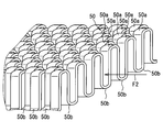
端側フィン部50は、例えば、オフセットフィンによって構成される。オフセットフィンは、図6に図示するように、第1の方向に隣り合う波形フィンが第1の方向に対して垂直な方向に沿って位置ずれするように配されるフィンである。またオフセットフィンは、第1の方向に隣り合う波形フィンが第1の方向に対して垂直な方向に沿って千鳥状に配されるフィンである。この実施形態では、一例として第1の方向が高温流体の流れる方向F2である構成について説明する。したがって、第1の方向は、方向F2に対して交差する方向であってもよい。さらに第1の方向は、各保持部材3,4における両端の接合部間を結ぶ線分が延びる方向(図のF2方向)であることが好ましい。
このように端側フィン部50は、第1の方向に垂直な方向に沿って山部50aと谷部50bとが交互に連なる波形状部を複数個有する。端側フィン部50は、第1の方向に沿って隣合う山部50aおよび隣合う谷部50bが第1の方向に垂直な方向に沿ってオフセットするように設けられるオフセットフィンを構成する。
オフセットフィンは、アルミニウムやアルミニウム合金等からなる板材を成形装置に投入してスリット加工、プレス成形加工することによって作製することができる。オフセットフィンは、通風方向に隣接する折り曲げ部の立ち上がりを通風方向に直交する方向に一定間隔ずらした形状になっている。例えば、図6に図示するように、通風方向に隣接する折り曲げ部の立ち上がりは、通風方向に直交する方向に半幅ずつずらした形状になっている。したがって、オフセットフィンは、通風方向に分断したフィンを形成するため、通風の乱流の発生を促進し、フィンと高温流体との間の熱伝達を向上することができる。
端側フィン部50は、中間フィン部51よりも、オフセット配置された関係にある隣合う山部50aや谷部50bが並ぶ方向、すなわち、第1の方向に剛性が弱い特性をもつ。これは、端側フィン部50においては、第1の方向に沿って並ぶ山部50aや谷部50bが、中間フィン部51のように第1の方向に沿って全体に連続して形成されているのではなく、半幅分程度ずれた位置で並ぶために分断されたフィン形状をなすからである。このような端側フィン部50が第1保持部材3にろう付けされることにより、各保持部材3,4は、端側フィン部50と一体になった部位が中間フィン部51と一体になった部位よりも剛性が低くなる。この結果、各保持部材3,4は、端側フィン部50と一体になった部位が曲がりやすくなる分、中間フィン部51と一体になった部位が曲がりにくくなり接触面圧の低下を抑制できる。したがって、全体として接触面圧の均一化を図ることができる。
また、第1保持部材3と発電モジュール1との間に、グラファイトシートを介在させてもよい。第2保持部材4と発電モジュール1との間に、グラファイトシートを介在させてもよい。さらに管6と発電モジュール1との間に、グラファイトシートを介在させてもよい。このように隙間が生じる可能性のある接触部には、グラファイトシートを設けることで、接触部に隙間ができる要因となる多少の高低差または凹凸を吸収でき、熱伝導性を確保することに貢献できる。
グラファイトシートは、非常に高い熱伝導率を有する。例えば、グラファイトシートは、銅やアルミニウムの2倍以上の熱伝導率を有するもの採用することが好ましい。グラファイトシートは、薄く、柔軟なシートであり、変形や加工が容易である。グラファイトシートは高分子フィルムを熱分解してグラファイト化することにより、製造することができる。また、グラファイトシートは、単結晶に近い構造を持つ高配向性を有するものであることが好ましい。
接合された状態の第1保持部材3と第2保持部材4は、例えば流れ方向F2の長さが130mm程度の寸法に設定されている。第1保持部材3と第2保持部材4とによって挟まれて保持される管6や熱交換用フィン5は、例えば流れ方向F2の長さが85mm程度の寸法に設定されている。管6は、例えば流れ方向F1の長さが160mm程度の寸法に設定されている。熱電発電装置100は、例えば図4に図示する積層方向の長さW、すなわち熱交換用フィン5の先端間の長さが約35mmの寸法に設定されている。
第1保持部材3と第2保持部材4とは、組み付け時において、接合部3aと接合部4aとが互いに重なる部分を増加させるように、図2の白抜き矢印で示す方向に加圧されている。この加圧された状態で接合部3aと接合部4aは、互いにシーム溶接またはレーザー溶接よって溶接されている。
これにより、第1保持部材3と第2保持部材4は、発電モジュール1を挟みこむ応力を作用させた製品を提供する。さらに発電モジュール1は、第1保持部材3と第2保持部材4と管6との両方に密接している。この加圧力は、管6と発電モジュール1との間、発電モジュール1と第1保持部材3および第2保持部材4との間に作用し、これらの部材間に接触部を形成する。
接合部3aと接合部4aの溶接は、低温流体が流れる方向に沿って延伸する溶接部を形成するシーム溶接またはレーザー溶接で提供される。これによれば、接合部3aと接合部4aを強固に溶接することができる。さらに接合部3aの先端面に溶接部を形成してもよい。
第1保持部材3および第2保持部材4は、発電モジュール1の両端部よりも外側で曲げられて弾性変形した状態で接合される。このため、発電モジュール1の端部では接触部を維持しながら、弾性変形した第1保持部材3と第2保持部材4とが元に戻ろうとする反力によって発電モジュール1、第1保持部材3、第2保持部材4および管6の密着性を確保することができる。
次に、第1実施形態の熱電発電装置100がもたらす作用効果について説明する。熱電発電装置100は、低温流体が流れる管6と、熱電変換素子を有し管6に積層して設けられる発電モジュール1と、第1保持部材3および第2保持部材4と、高温流体が接触する熱交換用フィン5と、を備える。第1保持部材3、第2保持部材4は、発電モジュール1および管6からなる積層体の両端部よりも外側に位置する両外側部位が固定された状態で発電モジュール1と管6とを熱移動可能に保持する。熱交換用フィン5は、積層体の両端部に対して保持部材3,4の反対側表面に設けられる一対の端側フィン部50と、端側フィン部50と端側フィン部50との間に設けられ端側フィン部50よりも剛性が高い中間フィン部51と、を含んで構成される。
この熱電発電装置100によれば、保持部材3,4は発電モジュール1および管6の積層体における両端部よりも外側に位置する両外側部位が固定された状態で積層体を熱移動可能に保持する保持力を提供する。このような保持力を提供する装置の場合、保持部材と発電モジュールとの接触面圧は積層体の両端部の方が中央部よりも大きくなるため、保持部材と発電モジュールとの接触面圧は全体として不均一になり保持部材と発電モジュールとの熱伝達性が悪くなる。
そこで熱電発電装置100によれば、保持部材3,4において両端部側に設けた端側フィン部50よりも中央部の中間フィン部51の剛性を高くなるように熱交換用フィン5を構成している。このため、中間フィン部51に相当する箇所において保持部材3,4の変形を抑制することできる。これにより、保持部材3,4は、熱交換用フィン5によって熱交換性能を確保することに加え、さらに熱交換用フィン5を活用することによって中央部における発電モジュール1との接触面圧と両端部側における発電モジュール1との接触面圧との差を抑制できる。したがって、熱電発電装置100は、熱電変換素子を保持する保持部材3,4と熱電変換素子との接触面圧の均一化が図れるので、保持部材3,4の浮き上がりを抑制して保持部材3,4と発電モジュール1との熱伝達性を確保できる。
保持部材は、互いに端部同士が結合された状態で発電モジュール1を保持する第1保持部材3と第2保持部材4とを含んで構成される。第1保持部材3と第2保持部材4、管6と、管6を挟むように両側に設けられた一対の発電モジュール1と、が積層された積層体を挟む保持力を提供する。
この熱電発電装置100によれば、第1流体が流れる管6を間においた両側で、第2流体からの熱回収を実施でき、発電モジュール1による発電を実施できる。したがって、高効率の発電および熱回収を実現し、かつ熱電変換素子の熱的保護も実施できる高性能と耐寿命との両立が図れる熱電発電装置100を提供できる。
中間フィン部51は、第1の方向に沿って連続して延びる板部を有するように第1の方向に垂直な断面形状が波形状に形成されたストレートフィンによって構成される。端側フィン部50は、オフセットフィンによって構成される。オフセットフィンは、第1の方向に垂直な方向に沿って山部50aと谷部50bとが交互に連なる波形状部を複数個有し、第1の方向に沿って隣合う山部50aおよび隣合う谷部50bが第1の方向に垂直な方向に沿ってオフセットするように設けられる。
この熱電発電装置100によれば、各保持部材3,4は、オフセットフィンが設けられた部位がストレートフィンが設けられた部位よりも剛性が低くなる。この結果、オフセットフィンの部位は中央部よりも曲がりやすくなるとともに熱交換性能の向上が図れ、ストレートフィンの部位は曲がりにくくなり接触面圧の低下抑制が図れる。したがって、全体として接触面圧の均一化を図るとともに、全体としての熱交換性能を図る熱電発電装置100を提供できる。
(第2実施形態)
第2実施形態に係る熱交換用フィンについて図7を参照して説明する。図7において第1実施形態の図面と同じ符号を付した構成は、第1実施形態と同様である。第2実施形態で特に説明しない構成、処理、作用、効果については、第1実施形態と同様である。以下、第1実施形態と異なる点についてのみ説明する。
第2実施形態に係る熱交換用フィンについて図7を参照して説明する。図7において第1実施形態の図面と同じ符号を付した構成は、第1実施形態と同様である。第2実施形態で特に説明しない構成、処理、作用、効果については、第1実施形態と同様である。以下、第1実施形態と異なる点についてのみ説明する。
第2実施形態の熱交換用フィンは、第1実施形態の熱交換用フィン5に対して、端側フィン部150の構成が相違する。第2実施形態の端側フィン部150は、第1実施形態の端側フィン部50と同様の作用効果を奏する。端側フィン部150は、高温流体の流れ方向に沿って連続して延びる板部を有するように第2流体の流れ方向に垂直な断面形状が波形状に形成されるストレートフィン部について、板部にルーバ150aを備えたフィン形状である。ルーバ150aは、板部に形成された切り起こし部、スリット状の開口部等によって形成することができる。
このような熱交換用フィンによれば、高温流体である第2流体は、端側フィン部150において、板部に沿う流れとルーバ150aを通過する流れとを形成する。このため、端側フィン部150において、乱流の発生が促進されて熱交換性能を向上することができる。
第2実施形態の熱交換用フィンによれば、端側フィン部150と中間フィン部51とを一体のストレートフィンとして形成できるため、個別に製作する手間が省け一部品として製作することができ、製造工数を低減することができる。また、端側フィン部150は、中間フィン部51と同様のフィン部にルーバ150aを形成する工程を加えるだけで製作できるので、大幅な工程追加を伴うことなくプレス加工によって製造することができる。
(第3実施形態)
第3実施形態に係る熱交換用フィンについて図8および図9を参照して説明する。第3実施形態で特に説明しない構成、処理、作用、効果については、前述の実施形態と同様である。以下、前述の実施形態と異なる点についてのみ説明する。
第3実施形態に係る熱交換用フィンについて図8および図9を参照して説明する。第3実施形態で特に説明しない構成、処理、作用、効果については、前述の実施形態と同様である。以下、前述の実施形態と異なる点についてのみ説明する。
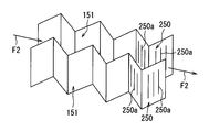
第3実施形態の熱交換用フィンは、図8に図示するように第2流体の流れ方向に沿って波形が進む形状に形成された複数の波形フィン部によって構成される点が、第2実施形態の熱交換用フィンに対して相違する。波形フィン部は、第2流体の流れ方向に沿った断面が、波形に形成されても良い。複数の波形フィン部は、第2流体の流れ方向について垂直な方向に、第2流体が流通する通路に相当する間隔をあけて配置されている。各波形フィン部は、中央部において中間フィン部151を構成し、中間フィン部151の両側において端側フィン部250を構成する。端側フィン部250は、両端部側において板部にルーバ250aを備えたフィン部である。ルーバ250aは、板部に形成された切り起こし部、スリット状の開口部等によって形成することができる。
このような熱交換用フィンによれば、高温流体である第2流体は、波形フィン部と波形フィン部との間を波状に蛇行しながら進むため、第2流体とフィン部との接触面積を拡大でき、乱流の発生が促進されて熱交換性能を向上することができる。
第3実施形態の熱交換用フィンによれば、一つの波形フィン部において、端側フィン部250と中間フィン部151とを有するように構成できるため、端側フィン部250と中間フィン部151を個別に製作する手間が省け一部品として製作することができる。また、端側フィン部250は、中間フィン部151と同様の波形フィン部にルーバ250aを形成する工程を加えるだけで製作できるので、大幅な工程追加を伴うことなくプレス加工によって製造することができる。
この明細書の開示は、例示された実施形態に制限されない。開示は、例示された実施形態と、それらに基づく当業者による変形態様を包含する。例えば、開示は、実施形態において示された部品、要素の組み合わせに限定されず、種々変形して実施することが可能である。開示は、多様な組み合わせによって実施可能である。開示は、実施形態に追加可能な追加的な部分をもつことができる。開示は、実施形態の部品、要素が省略されたものを包含する。開示は、ひとつの実施形態と他の実施形態との間における部品、要素の置き換え、または組み合わせを包含する。開示される技術的範囲は、実施形態の記載に限定されない。
前述する熱電発電装置100は、自動車以外に搭載される機器にも幅広く適用することができる。例えば、熱電発電装置100は、工業用や住宅用のボイラにおいて発生するガスを高温流体として用いる排熱回収装置と組み合わせたり、工場や焼却炉等の排熱を高温流体として利用する発電機、電気機器の電源装置、携帯型発電機等に適用したりすることができる。
熱電発電装置100は、図示した構成に限定されるものではない。例えば、熱電発電装置100は、管6の一方側のみで発電モジュール1と管6とを積層して形成される積層体を保持部材によって一体に保持する構成としてもよい。つまり、熱電発電装置100は、管6の片方側でのみ、積層体を保持する形態としてもよい。
前述の実施形態では、1つの発電ユニットからなる熱電発電装置100を開示しているが、熱電発電装置100は発電ユニットを複数積層して構成してもよい。この場合においても高温流体が、積層された発電ユニット相互間に位置する熱交換用フィン5に接して流れるように構成される。
第1実施形態の中間フィン部51における板部は、方向F2に沿って連続して延びる形態に限定されない。中間フィン部51における板部は、方向F2に交差する方向に沿って連続して延びる形態でもよい。
前述の実施形態においては、第1保持部材3を第2保持部材4よりも小さくして、第1保持部材3を第2保持部材4に被せるようにして組み付けているが、第1保持部材3と第2保持部材4とを同じ大きさにして互い違いに組み合わせて組み付けるようにしてもよい。
前述の実施形態においては、第1保持部材3と第2保持部材4とを溶接して、第1保持部材3と第2保持部材4とで囲まれた内部空間を外部から密封している。しかしながら、第1保持部材3と第2保持部材4とを完全に密封せず、高温流体が内部空間の発電モジュール1に悪影響を及ぼさない程度に結合するようにしてもよい。例えば、第1保持部材3と第2保持部材4とを多数点のスポット溶接で結合してもよい。
前述の実施形態の発電モジュール1は、ケースによって覆われる構成ではなく、多数のP型半導体素子とN型半導体素子とが第1保持部材3と第2保持部材4とで囲まれた内部空間に露出して設けられる構成でもよい。熱電発電装置100においてケースは必須の構成要素ではない。この場合は、内部空間をカバー等で密封することが好ましい。
前述の実施形態において、第1保持部材3の接合部3aと第2保持部材4の接合部4aとの接合面は平坦なものであるが、接合面に、互いに係合して後戻りしない鋸歯状の突起形状やラビリンス形状を構成する凹凸形状を形成する構成でもよい。
前述の実施形態において、第1保持部材3および第2保持部材4と発電モジュール1とが接する部分は平面としているが、湾曲形状としてもよい。第1保持部材3および第2保持部材4と発電モジュール1との間には、熱伝導に優れたグリス等の熱的連絡部材を設けてもよい。この熱的連絡部材は、管6、第1保持部材3、第2保持部材4よりも、外力によって変形しやすく硬度が低い部材であることが好ましい。この構成によれば、熱的連絡部材は、各部材の膨張や収縮に応じて変形可能であるため、管6、第1保持部材3、第2保持部材4に対して発電モジュール1を変位させやすくできる。したがって、高温流体および低温流体によりもたらされる温度差によって各部材が膨張や収縮したとしても、発電モジュール1は変位しやすいので、各部材の歪みによる応力を軽減したり、部材間の熱膨張差を吸収したりする効果を高めることができる。
前述の実施形態では、第2通路を形成する扁平状の管6は、内部に複数の通路を有するものであるが、このような形態に限定されない。また管6は、扁平状でない外形形状でもよいし、内部にフィンを備える形態でもよい。
前述の実施形態において、低温流体と高温流体は、互いに逆向きに流れる対向流を形成してもよい。
本開示は、実施例に準拠して記述されたが、本開示は当該実施例や構造に限定されるものではないと理解される。本開示は、様々な変形例や均等範囲内の変形をも包含する。加えて、様々な組み合わせや形態が本開示に示されているが、それらに一要素のみ、それ以上、あるいはそれ以下、を含む他の組み合わせや形態をも、本開示の範疇や思想範囲に入るものである。
Claims (8)
- 内部に第1流体が流れる管(6)と、
内部に熱電変換素子を有し、前記管に積層して設けられる発電モジュール(1)と、
前記発電モジュールおよび前記管が積層して形成される積層体の両端部よりも外側に位置する両外側部位(3a,4a)が固定された状態で前記発電モジュールと前記管とを熱移動可能に保持する保持力を提供する保持部材(3,4)と、
前記保持部材において前記発電モジュールに接する面とは反対側の表面に設けられ、前記第1流体よりも高温である第2流体が接触する熱交換用フィン(5)と、
を備え、
前記熱交換用フィンは、前記積層体の前記両端部に対して前記保持部材の反対側表面に設けられる一対の端側フィン部(50,150,250)と、前記端側フィン部と前記端側フィン部との間に設けられ前記端側フィン部よりも剛性が高い中間フィン部(51,151)と、を含んで構成される熱電発電装置。 - 前記保持部材は、第1保持部材(3)と第2保持部材(4)とを含み、前記第1保持部材と前記第2保持部材は、前記第1保持部材(3)の端部(3a)と前記第2保持部材(4)の端部(4a)が互いに結合された状態で前記発電モジュールを保持し、
前記第1保持部材と前記第2保持部材は、前記管と、前記管を挟むように両側に設けられた一対の前記発電モジュールと、が積層された積層体を挟む保持力を提供する請求項1に記載の熱電発電装置。 - 前記中間フィン部(51)は、第1の方向に沿って連続して延びる板部を有し、前記第1の方向に垂直な断面形状が波形状に形成されたストレートフィンによって構成され、
前記端側フィン部は、前記第1の方向に垂直な方向に沿って山部(50a)と谷部(50b)とが交互に連なる波形状部を複数個有し、前記第1の方向に沿って隣合う前記山部および隣合う前記谷部が前記第1の方向に垂直な方向に沿ってオフセットして設けられるオフセットフィンによって構成される請求項1または請求項2に記載の熱電発電装置。 - 前記中間フィン部(51)は、前記第2流体の流れ方向に沿って連続して延びる板部を有し、前記第2流体の流れ方向に垂直な断面形状が波形状に形成されたストレートフィン部によって構成され、
前記端側フィン部(150)は、前記第2流体の流れ方向に沿って連続して延びる板部を有し、前記第2流体の流れ方向に垂直な断面形状が波形状に形成され、前記板部にルーバ(150a)を備えるストレートフィン部によって構成される請求項1または請求項2に記載の熱電発電装置。 - 前記中間フィン部(151)は、前記第2流体の流れ方向に沿った断面が波形である複数の波形フィン部によって構成され、
前記端側フィン部(250)は、前記第2流体の流れ方向に沿った断面が波形であり、かつルーバ(250a)が設けられた複数の波形フィン部によって構成される請求項1または請求項2に記載の熱電発電装置。 - 前記保持部材は、前記保持部材と前記発電モジュールとの間に設けられたグラファイトシートを介して前記発電モジュールに接触している請求項1から請求項5のいずれか一項に記載の熱電発電装置。
- 前記管は、前記発電モジュールと接触する面を有し、
前記管は、断面が扁平形状を有し、
前記保持部材の前記両外側部位は、前記管の前記扁平形状の長手方向において、前記積層体の両端部よりも外側に位置する、請求項1から請求項6のいずれか一項に記載の熱電発電装置。 - 内部に第1流体が流れる管(6)と、
内部に熱電変換素子を有し、前記管に積層して設けられる発電モジュール(1)と、
前記発電モジュールおよび前記管が積層して形成される積層体の両端部よりも外側に位置する両外側部位(3a,4a)が固定された状態で前記発電モジュールと前記管とを熱移動可能に保持する保持力を提供する保持部材(3,4)と、
前記保持部材において前記発電モジュールに接する面とは反対側の表面に設けられ、前記第1流体よりも高温である第2流体が接触する熱交換用フィン(5)と、
を備え、
前記積層体の前記両端部は、前記第1流体の流れ方向と交差する方向における端部であり、
前記熱交換用フィンは、前記積層体の前記両端部に対して前記保持部材の反対側表面に設けられる一対の端側フィン部(50,150,250)と、前記端側フィン部と前記端側フィン部との間に設けられ前記端側フィン部よりも剛性が高い中間フィン部(51,151)と、を含んで構成される熱電発電装置。
Priority Applications (2)
| Application Number | Priority Date | Filing Date | Title |
|---|---|---|---|
| US16/091,125 US10777725B2 (en) | 2016-04-06 | 2017-03-24 | Thermoelectric generator |
| DE112017001924.9T DE112017001924T5 (de) | 2016-04-06 | 2017-03-24 | Thermoelektrischer Generator |
Applications Claiming Priority (2)
| Application Number | Priority Date | Filing Date | Title |
|---|---|---|---|
| JP2016076846A JP6428701B2 (ja) | 2016-04-06 | 2016-04-06 | 熱電発電装置 |
| JP2016-076846 | 2016-04-06 |
Publications (1)
| Publication Number | Publication Date |
|---|---|
| WO2017175601A1 true WO2017175601A1 (ja) | 2017-10-12 |
Family
ID=60000441
Family Applications (1)
| Application Number | Title | Priority Date | Filing Date |
|---|---|---|---|
| PCT/JP2017/011947 Ceased WO2017175601A1 (ja) | 2016-04-06 | 2017-03-24 | 熱電発電装置 |
Country Status (4)
| Country | Link |
|---|---|
| US (1) | US10777725B2 (ja) |
| JP (1) | JP6428701B2 (ja) |
| DE (1) | DE112017001924T5 (ja) |
| WO (1) | WO2017175601A1 (ja) |
Cited By (1)
| Publication number | Priority date | Publication date | Assignee | Title |
|---|---|---|---|---|
| JP2023170341A (ja) * | 2022-05-19 | 2023-12-01 | 株式会社日立製作所 | 冷却装置 |
Families Citing this family (7)
| Publication number | Priority date | Publication date | Assignee | Title |
|---|---|---|---|---|
| US20190215984A1 (en) * | 2018-01-09 | 2019-07-11 | Aptiv Technologies Limited | Wireless device charger with cooling device |
| DE102018115501A1 (de) * | 2018-06-27 | 2020-01-02 | Faurecia Emissions Control Technologies, Germany Gmbh | Thermoelektrisches Generatormodul und Verfahren zur Herstellung eines thermoelektrischen Generatormoduls |
| US20200166293A1 (en) * | 2018-11-27 | 2020-05-28 | Hamilton Sundstrand Corporation | Weaved cross-flow heat exchanger and method of forming a heat exchanger |
| JP7539908B2 (ja) * | 2019-02-26 | 2024-08-26 | エルジー イノテック カンパニー リミテッド | 熱電モジュール |
| US11064632B2 (en) * | 2019-09-05 | 2021-07-13 | Ldc Precision Engineering Co., Ltd. | Heat-sinking improved structure for evaporators |
| USD933617S1 (en) * | 2019-09-13 | 2021-10-19 | Marvell Asia Pte, Ltd. | Heat sink cover |
| KR102606271B1 (ko) * | 2021-12-24 | 2023-11-24 | 삼성중공업 주식회사 | 열전발전용 방열핀 및 방열어셈블리 |
Citations (10)
| Publication number | Priority date | Publication date | Assignee | Title |
|---|---|---|---|---|
| JPH10234194A (ja) * | 1997-02-20 | 1998-09-02 | Calsonic Corp | 排熱発電装置 |
| JP2000172347A (ja) * | 1998-12-03 | 2000-06-23 | Komatsu Ltd | ヒートパイプを利用した温度制御装置 |
| JP2002238272A (ja) * | 2001-02-06 | 2002-08-23 | Tokyo Gas Co Ltd | 高温排熱利用発電装置 |
| JP2006303037A (ja) * | 2005-04-18 | 2006-11-02 | Toyota Motor Corp | 熱電発電装置 |
| US20080028769A1 (en) * | 2006-08-02 | 2008-02-07 | Lakhi Nandlal Goenka | Heat exchanger tube having integrated thermoelectric devices |
| JP2008148432A (ja) * | 2006-12-08 | 2008-06-26 | Toyota Motor Corp | 熱発電装置 |
| US20140150840A1 (en) * | 2011-03-11 | 2014-06-05 | Faurecia Emissions Control Technologies, Germany Gmbh | Thermoelectric Generator Unit |
| JP2014127617A (ja) * | 2012-12-27 | 2014-07-07 | Toyota Motor Corp | 熱電発電装置 |
| JP2015032657A (ja) * | 2013-08-01 | 2015-02-16 | トヨタ自動車株式会社 | 熱電発電装置 |
| JP2015097228A (ja) * | 2013-11-15 | 2015-05-21 | トヨタ自動車株式会社 | 熱電発電装置 |
Family Cites Families (5)
| Publication number | Priority date | Publication date | Assignee | Title |
|---|---|---|---|---|
| CN102742040B (zh) * | 2010-03-25 | 2016-03-23 | 京瓷株式会社 | 热电元件及热电模块 |
| JP5956155B2 (ja) | 2012-01-05 | 2016-07-27 | フタバ産業株式会社 | 熱電発電装置 |
| DE112013000620T5 (de) * | 2012-01-20 | 2014-10-16 | Gentherm Incorporated | Integrierter Katalysator/Thermoelektrischer Generator |
| BR112015022574B1 (pt) * | 2013-03-15 | 2022-01-25 | Vecarius, Inc | Dispositivo e sistema termoelétrico |
| JP6398569B2 (ja) | 2014-10-07 | 2018-10-03 | 株式会社ソシオネクスト | 画像符号化装置、画像符号化方法および画像符号化プログラム |
-
2016
- 2016-04-06 JP JP2016076846A patent/JP6428701B2/ja not_active Expired - Fee Related
-
2017
- 2017-03-24 US US16/091,125 patent/US10777725B2/en not_active Expired - Fee Related
- 2017-03-24 DE DE112017001924.9T patent/DE112017001924T5/de not_active Withdrawn
- 2017-03-24 WO PCT/JP2017/011947 patent/WO2017175601A1/ja not_active Ceased
Patent Citations (10)
| Publication number | Priority date | Publication date | Assignee | Title |
|---|---|---|---|---|
| JPH10234194A (ja) * | 1997-02-20 | 1998-09-02 | Calsonic Corp | 排熱発電装置 |
| JP2000172347A (ja) * | 1998-12-03 | 2000-06-23 | Komatsu Ltd | ヒートパイプを利用した温度制御装置 |
| JP2002238272A (ja) * | 2001-02-06 | 2002-08-23 | Tokyo Gas Co Ltd | 高温排熱利用発電装置 |
| JP2006303037A (ja) * | 2005-04-18 | 2006-11-02 | Toyota Motor Corp | 熱電発電装置 |
| US20080028769A1 (en) * | 2006-08-02 | 2008-02-07 | Lakhi Nandlal Goenka | Heat exchanger tube having integrated thermoelectric devices |
| JP2008148432A (ja) * | 2006-12-08 | 2008-06-26 | Toyota Motor Corp | 熱発電装置 |
| US20140150840A1 (en) * | 2011-03-11 | 2014-06-05 | Faurecia Emissions Control Technologies, Germany Gmbh | Thermoelectric Generator Unit |
| JP2014127617A (ja) * | 2012-12-27 | 2014-07-07 | Toyota Motor Corp | 熱電発電装置 |
| JP2015032657A (ja) * | 2013-08-01 | 2015-02-16 | トヨタ自動車株式会社 | 熱電発電装置 |
| JP2015097228A (ja) * | 2013-11-15 | 2015-05-21 | トヨタ自動車株式会社 | 熱電発電装置 |
Cited By (1)
| Publication number | Priority date | Publication date | Assignee | Title |
|---|---|---|---|---|
| JP2023170341A (ja) * | 2022-05-19 | 2023-12-01 | 株式会社日立製作所 | 冷却装置 |
Also Published As
| Publication number | Publication date |
|---|---|
| JP2017188594A (ja) | 2017-10-12 |
| US10777725B2 (en) | 2020-09-15 |
| DE112017001924T5 (de) | 2019-01-10 |
| US20190115519A1 (en) | 2019-04-18 |
| JP6428701B2 (ja) | 2018-11-28 |
Similar Documents
| Publication | Publication Date | Title |
|---|---|---|
| JP6428701B2 (ja) | 熱電発電装置 | |
| JP6078412B2 (ja) | 熱電変換式発電装置 | |
| JP2010245265A (ja) | 熱電モジュール | |
| JP6390676B2 (ja) | 熱電発電装置 | |
| JP2019046707A (ja) | 電池モジュール | |
| JP2011165976A (ja) | 熱電気変換装置および熱電気変換方法 | |
| JP2017059821A5 (ja) | 熱電発電装置 | |
| JP6358209B2 (ja) | 熱電発電装置 | |
| JP6039348B2 (ja) | 熱電変換式発電装置 | |
| WO2017212822A1 (ja) | 熱電発電装置 | |
| JP6428749B2 (ja) | 熱電発電装置 | |
| JP4923997B2 (ja) | 熱発電装置 | |
| JP6424883B2 (ja) | 熱電発電装置 | |
| JP6641858B2 (ja) | 熱電変換モジュール及び熱電変換器並びに熱電変換モジュールの製造方法 | |
| JP2018191490A (ja) | 熱電発電装置 | |
| WO2017126264A1 (ja) | 熱電発電装置 | |
| WO2017047562A1 (ja) | 熱電発電装置及びその製造方法 | |
| JP2015126117A (ja) | 半導体モジュールの冷却装置 | |
| JP2015138790A (ja) | 熱電変換式発電装置 | |
| JP2015201470A (ja) | 熱電変換式発電装置 | |
| JP2017017903A (ja) | 熱電発電装置 |
Legal Events
| Date | Code | Title | Description |
|---|---|---|---|
| 121 | Ep: the epo has been informed by wipo that ep was designated in this application |
Ref document number: 17778980 Country of ref document: EP Kind code of ref document: A1 |
|
| 122 | Ep: pct application non-entry in european phase |
Ref document number: 17778980 Country of ref document: EP Kind code of ref document: A1 |