WO2017175543A1 - パワーステアリング装置の制御装置およびパワーステアリング装置 - Google Patents
パワーステアリング装置の制御装置およびパワーステアリング装置 Download PDFInfo
- Publication number
- WO2017175543A1 WO2017175543A1 PCT/JP2017/009900 JP2017009900W WO2017175543A1 WO 2017175543 A1 WO2017175543 A1 WO 2017175543A1 JP 2017009900 W JP2017009900 W JP 2017009900W WO 2017175543 A1 WO2017175543 A1 WO 2017175543A1
- Authority
- WO
- WIPO (PCT)
- Prior art keywords
- steering
- command signal
- characteristic information
- assist
- unit
- Prior art date
Links
Images


Classifications
-
- B—PERFORMING OPERATIONS; TRANSPORTING
- B62—LAND VEHICLES FOR TRAVELLING OTHERWISE THAN ON RAILS
- B62D—MOTOR VEHICLES; TRAILERS
- B62D5/00—Power-assisted or power-driven steering
- B62D5/04—Power-assisted or power-driven steering electrical, e.g. using an electric servo-motor connected to, or forming part of, the steering gear
- B62D5/0457—Power-assisted or power-driven steering electrical, e.g. using an electric servo-motor connected to, or forming part of, the steering gear characterised by control features of the drive means as such
- B62D5/046—Controlling the motor
- B62D5/0463—Controlling the motor calculating assisting torque from the motor based on driver input
-
- B—PERFORMING OPERATIONS; TRANSPORTING
- B62—LAND VEHICLES FOR TRAVELLING OTHERWISE THAN ON RAILS
- B62D—MOTOR VEHICLES; TRAILERS
- B62D5/00—Power-assisted or power-driven steering
- B62D5/04—Power-assisted or power-driven steering electrical, e.g. using an electric servo-motor connected to, or forming part of, the steering gear
- B62D5/0457—Power-assisted or power-driven steering electrical, e.g. using an electric servo-motor connected to, or forming part of, the steering gear characterised by control features of the drive means as such
- B62D5/0481—Power-assisted or power-driven steering electrical, e.g. using an electric servo-motor connected to, or forming part of, the steering gear characterised by control features of the drive means as such monitoring the steering system, e.g. failures
- B62D5/049—Power-assisted or power-driven steering electrical, e.g. using an electric servo-motor connected to, or forming part of, the steering gear characterised by control features of the drive means as such monitoring the steering system, e.g. failures detecting sensor failures
Definitions
- the present invention relates to a control device for a power steering device and a power steering device.
- Patent Document 1 discloses one that sets an assist limit that limits the assist torque to be applied by the power steering device in accordance with the location where an abnormality has occurred in the system.
- the upper limit value of the assist torque is limited by the assist limit.
- the assist torque applied during normal travel is relatively small and may not reach the upper limit value limited by the assist limit.
- the assist limit is set to limit the assist torque more when the number of abnormal points in the system increases. If the assist torque limit increases, the assist torque will reach the upper limit value limited by the assist limit even during normal driving, so the driver can feel that the steering reaction force has increased, and an abnormality will occur in the system. Can be recognized. However, since the driver feels that the steering reaction force suddenly increases, the influence on steering is large.
- the object of the present invention is to gradually increase the steering reaction force felt by the driver after the start of assist limitation when performing assist limitation that reduces the power supplied to the electric motor that applies the steering force. It is an object of the present invention to provide a power steering device control device and a power steering device.
- a control device for a power steering device that applies a steering force to a steering mechanism by an electric motor is configured to drive and control the electric motor as the steering torque increases.
- a command signal calculation unit having characteristic information for increasing the command signal, a characteristic information correction unit for correcting the characteristic information so that the command signal gradually decreases with the reception of the assist restriction command signal, and the electric motor driven based on the command signal A drive power supply unit for supplying power.
- a power steering device that applies a steering force to a steering mechanism by an electric motor includes a controller.
- the controller has a characteristic that the command signal gradually decreases with the reception of the assist limit command signal and the command signal calculation unit having the characteristic information for increasing the command signal for driving and controlling the electric motor as the steering torque increases.
- a characteristic information correction unit that corrects information; and a drive power supply unit that supplies drive power to the electric motor based on the command signal.
- the steering reaction force felt by the driver can be gradually increased after the start of assist limitation.
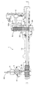
- FIG. 1 is a perspective view of a power steering device of Embodiment 1.
- FIG. FIG. 3 is a cross-sectional view of the power steering device according to the first embodiment cut along the axis of a turning shaft.
- 1 is a schematic diagram of a power steering device according to Embodiment 1.
- FIG. 1 is a block diagram of an electric system of Example 1.
- FIG. 1 is a sensor block diagram of Embodiment 1.
- 2 is a control block diagram of Embodiment 1.
- FIG. 3 is a graph showing a motor command current map of Example 1.
- 3 is a flowchart showing a flow of processing performed in the electronic control unit when the sensor of the first embodiment is abnormal.
- 3 is a flowchart illustrating a flow of assist torque gradual reduction processing according to the first embodiment.
- 6 is a flowchart illustrating a flow of Limp-Home processing A according to the first embodiment.
- 6 is a flowchart illustrating a flow of Limp-Home processing B according to the first embodiment.
- 3 is a time chart at the time of assist torque gradual reduction processing according to the first embodiment.
- 2 is a target assist torque map according to the first embodiment.
- 2 is a target assist torque map according to the first embodiment.
- 2 is a target assist torque map according to the first embodiment.
- 6 is a time chart during Limp-Home processing A of the first embodiment.
- 2 is a target assist torque map according to the first embodiment.
- 2 is a target assist torque map according to the first embodiment.
- 2 is a target assist torque map according to the first embodiment.
- 2 is a target assist torque map according to the first embodiment. 6 is a time chart during Limp-Home processing B of the first embodiment. 2 is a target assist torque map according to the first embodiment. 2 is a target assist torque map according to the first embodiment. 2 is a target assist torque map according to the first embodiment. 2 is a target assist torque map according to the first embodiment. 2 is a target assist torque map according to the first embodiment.
- FIG. 1 is a perspective view of the power steering apparatus 1.
- FIG. 2 is a cross-sectional view of the power steering device 1 cut along the axis of the steered shaft 10.
- the power steering device 1 includes a steering mechanism 2 that transmits rotation of a steering wheel steered by a driver to a steered shaft 10 that steers steered wheels, and an assist mechanism 3 that applies torque to the steered shaft 10. is doing.
- Each component of the power steering device 1 is accommodated in a housing 30 including a first housing 31, a second housing 32, and a motor housing 33.
- the steering mechanism 2 has a steering input shaft 80 connected to the steering wheel.
- a pinion 81 is formed at the tip of the steering input shaft 80.
- the pinion 81 meshes with a rack formed on the outer periphery of the steered shaft 10.
- the assist mechanism 3 includes an electric motor 40 and a ball screw mechanism 26 that transmits the output of the electric motor 40 to the steered shaft 10.
- the output of the electric motor 40 is controlled by the electronic control unit 7 (FIGS. 4, 5, and 6) according to the steering torque and the steering amount input to the steering wheel by the driver.
- the ball screw mechanism 26 includes a nut 20 and an output pulley 27.
- the appearance of the output pulley 27 is a cylindrical member, and is fixed to the nut 20 so as to be integrally rotatable.
- a cylindrical input pulley 35 is fixed to the drive shaft 40a of the electric motor 40 so as to rotate integrally.
- the rotation axis of the nut 20 is a first reference axis L1
- the rotation axis of the input pulley 35 is a second reference axis L2.
- the second reference axis L2 is arranged so as to be offset in the radial direction with respect to the first reference axis L1.
- the output pulley 27 fixed integrally with the nut 20 also has the first reference axis L1 as the rotation axis.
- a belt 28 is wound between the input pulley 35 and the output pulley 27.
- the belt 28 is made of resin.
- the driving force of the electric motor 40 is transmitted to the nut 20 via the input pulley 35, the belt 28, and the output pulley 27.
- the outer diameter of the input pulley 35 is smaller than the outer diameter of the output pulley 27.
- the input pulley 35, the output pulley 27, and the belt 28 constitute a speed reducer.
- the nut 20 is formed in a cylindrical shape so as to surround the steered shaft 10, and is provided to be rotatable with respect to the steered shaft 10.
- a groove is spirally formed on the inner periphery of the nut 20, and this groove forms a nut-side ball screw groove 21.
- a spiral groove is formed on the outer periphery of the turning shaft 10 at a position away from the portion where the rack is formed in the axial direction, and this groove constitutes the turning shaft side ball screw groove 11. .
- a ball circulation groove 12 is formed by the nut-side ball screw groove 21 and the steered shaft-side ball screw groove 11.
- the ball circulation groove 12 is filled with a plurality of balls 22 made of metal.
- FIG. 3 is a schematic diagram of the power steering apparatus 1.
- the power steering device 1 includes a steering torque sensor 4 that detects a steering torque input to a steering wheel by a driver, a steering angle sensor 5 that detects a steering angle of the steering wheel, and a motor that detects a rotation angle of a rotor of the electric motor 40.
- a rotation angle sensor 6 is provided.
- the steering torque sensor 4 detects the steering torque based on the torsion amount of the torsion bar 41 provided between the steering input shaft 80 and the pinion 81.
- the torsion amount of the torsion bar 41 can be obtained from the difference between the rotation angle of the steering input shaft 80 and the rotation angle of the pinion 81.
- Ts Ktb ( ⁇ s- ⁇ p)
- the steering angle sensor 5 detects the rotation angle of the steering input shaft 80 as a steering angle.
- the steering angle sensor 5 is provided closer to the steering wheel than the torsion bar 41.
- the steering torque can be obtained from the detected value of the steering angle sensor 5 and the detected value of the motor rotation angle sensor 6.
- the detected value of the steering angle sensor 5 may be used as the rotation angle ⁇ s [deg] of the steering input shaft 80.
- the rotation angle ⁇ p [deg] of the pinion 81 is obtained by the following equation using the rotation angle ⁇ m [deg] of the rotor of the electric motor 40 and the reduction ratio Ng between the pinion 81 and the drive shaft 40a of the electric motor 40. be able to.
- ⁇ p Ng ⁇ ⁇ m
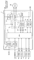
- FIG. 4 is an electrical system block diagram.
- the steering torque sensor 4 has two sensors, a main steering torque sensor 4a and a sub steering torque sensor 4b.
- the steering angle sensor 5 has two sensors, a main steering angle sensor 5a and a sub steering angle sensor 5b.
- the motor rotation angle sensor 6 has two sensors, a main motor rotation angle sensor 6a and a sub motor rotation angle sensor 6b.
- the motor rotation angle sensor 6 is incorporated in the electronic control unit 7.
- the electronic control unit 7 includes a power supply circuit 70, a CAN communication circuit 71, a microprocessor 72, a pre-driver 73, a current monitoring circuit 74, a fail-safe circuit 75, an inverter circuit 76, an ammeter 77, a first current detection circuit 78, a first A two-current detection circuit 79 is provided.
- the power supply circuit 70 supplies power from the battery to the steering torque sensor 4, the steering angle sensor 5, the motor rotation angle sensor 6, the microprocessor 72, and the predriver 73.
- the CAN communication circuit 71 exchanges signals with a controller area network (CAN).
- the microprocessor 72 receives the vehicle speed information of the host vehicle from the CAN communication circuit 71, the steering torque information from the steering torque sensor 4, the steering angle information from the steering angle sensor 5, the motor rotation angle information from the motor rotation angle sensor 6, and the first current detection. Current value information is input from the circuit 78 and the second current detection circuit 79.
- the microprocessor 72 calculates a motor command current output from the electric motor 40 based on the input information, and outputs it to the pre-driver 73.
- the pre-driver 73 generates a PWM duty signal for controlling the inverter circuit 76 based on the motor command current calculated in the microprocessor 72, and outputs the PWM duty signal to the inverter circuit 76.
- the current monitoring circuit 74 inputs a detection value of an ammeter 77 that detects a current flowing through the inverter circuit 76.
- the current monitoring circuit 74 monitors whether or not a current value necessary for controlling the electric motor 40 is output as intended in order to output the assist torque calculated by the microprocessor 72.
- the pre-driver 73 and the current monitoring circuit 74 constitute a motor control circuit 7g.
- the fail safe circuit 75 detects a system abnormality in the microprocessor 72, and when it is determined to shut down the system, the power supply from the inverter circuit 76 to the electric motor 40 is cut off based on a command from the microprocessor 72. To do.
- the inverter circuit 76 includes a drive element for supplying current to the electric motor 40.
- the inverter circuit 76 supplies a drive current to the electric motor 40 based on a command from the pre-driver 73.
- the first current detection circuit 78 performs high-response filter processing on the current value input to the current monitoring circuit 74 and outputs the result to the microprocessor 72.
- the second current detection circuit 79 performs low response filter processing on the current value input to the current monitoring circuit 74 and outputs the result to the microprocessor 72.
- the current value that has been subjected to the high-response filter process is used to control the electric motor 40.
- the current value subjected to the low response filter processing becomes an average current value, and is used for monitoring the eddy current of the inverter circuit 76.
- FIG. 5 is a sensor block diagram.
- the main steering torque sensor 4a is connected to the microprocessor 72 via a main steering torque signal receiver 7b provided in the electronic control unit 7.
- the sub steering torque sensor 4b is connected to the microprocessor 72 via a sub steering torque signal receiving unit 7d provided in the electronic control unit 7.
- the main steering angle sensor 5a is connected to the microprocessor 72 via a main steering angle signal receiver 7a provided in the electronic control unit 7.
- the sub steering angle sensor 5b is connected to the microprocessor 72 via a sub steering angle signal receiving unit 7c provided in the electronic control unit 7.
- the main motor rotation angle sensor 6a and the sub motor rotation angle sensor 6b are connected to the microprocessor 72 via a motor rotation angle signal receiving unit 7e provided in the electronic control unit 7.
- the main steering torque sensor 4a, the sub steering torque sensor 4b, the main steering angle sensor 5a, and the sub steering angle sensor 5b are connected to an abnormality detection circuit 7f provided in the electronic control unit 7.
- the abnormality detection circuit 7f monitors the abnormality of each sensor and outputs information on the sensor in which the abnormality has occurred to the microprocessor 72 when the abnormality has occurred in the sensor.
- Each signal receiving unit uses an interface of the microprocessor 72 in the first embodiment, but may be realized by software.
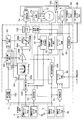
- FIG. 6 is a control block diagram.
- the electronic control unit 7 includes a motor command current calculation unit 90, an alternative steering torque signal calculation unit 91, an alternative motor rotation angle signal calculation unit 92, a steering torque sensor redundancy monitoring unit 93, a steering angle sensor redundancy monitoring unit 94, and a motor rotation angle sensor.
- a redundancy monitoring unit 95, a fail safe determination unit 96, a fail safe processing unit 97, a characteristic information correction unit 98, a limiter setting unit 99, and a supply power limiting unit 100 are provided.
- Each component in the electronic control unit 7 is realized by software in the first embodiment, but may be realized by an electronic circuit.
- the calculation performed in each configuration means not only mathematical calculation but also general processing on software.
- the motor command current calculation unit 90 includes a motor command current map 90a, a gain 90b, a steering assist control unit 90c, an addition unit 90d, and a limiter 90e.
- the motor command current map 90a receives a steering torque signal and a vehicle speed signal, and obtains a motor command current from the input information.
- FIG. 7 is a graph showing a motor command current map 90a.
- the motor command current map 90a is a map for obtaining the motor command current from the steering torque.
- the motor command current is set so as to increase as the steering torque increases.
- the motor command current is set so as to decrease as the vehicle speed increases.
- the motor command current map 90a has the map shown in FIG. 7, but the motor command current may be obtained by calculation without the map.
- the output torque of the electric motor 40 is transmitted to the steered shaft 10 via the ball screw mechanism 26. As a result, the steering torque of the driver is reduced, but the reduced torque is used as the assist torque below.
- the assist torque when the electric motor 40 is controlled by the motor command current obtained in the motor command current map 90a is hereinafter referred to as target assist torque.
- the electric motor 40 is torque controlled. That is, the motor command current has a high correlation with the target assist torque and is approximately proportional.
- the gain 90b multiplies the motor command current obtained in the motor command current map 90a.
- the gain is a numerical value of 1 or less, and is set in the characteristic information correction unit 98. Note that a gain may be applied to the entire data in the motor command current map 90a.
- the characteristic information correction unit 98 receives a vehicle speed signal, a steering torque signal, and a steering frequency signal. The characteristic information correction unit 98 sets the gain based on the processing commanded from the fail safe processing unit 97.
- the steering frequency signal is calculated in the steering frequency signal calculation unit 103 according to the steering speed obtained from the steering angle signal.
- the steering assist control unit 90c receives a steering angle signal, and calculates a motor command current for applying assist torque when the steering wheel is steered in the return direction from the input information (return control).
- the adder 90d adds the output value of the gain 90b and the output value of the steering assist controller 90c, and outputs the result as a motor command current.
- the limiter 90e inputs the motor command current of the adding unit 90d. When the input motor command current exceeds the set upper limit value, the upper limit value is output as the motor command current.
- the upper limit value is set by the limiter setting unit 99.
- the limiter setting unit 99 inputs a vehicle speed signal, a steering torque signal, and a steering frequency signal.
- the limiter setting unit 99 sets an upper limit value in the limiter 90e based on the process commanded from the fail safe processing unit 97.
- the alternative steering torque signal calculation unit 91 inputs the steering angle signal of the main steering angle sensor 5a and the motor rotation angle signal of the main motor rotation angle sensor 6a.
- the alternative steering torque signal calculation unit 91 calculates the rotation angle (pinion rotation angle) of the pinion 81 from the motor rotation angle signal.
- the pinion rotation angle can be obtained from the reduction ratio from the drive shaft 40a of the electric motor 40 to the pinion 81 and the motor rotation angle.
- the alternative steering torque signal calculation unit 91 calculates a steering torque from the steering angle signal and the calculated pinion rotation angle, and outputs it as an alternative steering torque signal.
- the alternative motor rotation angle signal calculation unit 92 inputs the steering angle signal of the main steering angle sensor 5a and the control signal of the inverter circuit 76 of the motor control circuit 7g.
- the alternative motor rotation angle signal calculation unit 92 calculates the motor rotation angle from the steering angle signal.
- the motor rotation angle can be obtained from the reduction ratio from the steering input shaft 80 to the electric motor 40 and the steering angle.
- the alternative motor rotation angle signal calculation unit 92 outputs the calculated motor rotation angle as an alternative motor rotation angle signal.
- the steering torque sensor redundancy monitoring unit 93 compares the output value of the main steering torque sensor 4a and the output value of the sub steering torque sensor 4b. If the difference between the output values is larger than a predetermined value, an abnormality occurs in the steering torque sensor 4.
- the steering angle sensor redundancy monitoring unit 94 compares the output value of the main steering angle sensor 5a and the output value of the sub steering angle sensor 5b. If the difference between the output values is larger than a predetermined value, an abnormality occurs in the steering angle sensor 5.
- the motor rotation angle sensor redundancy monitoring unit 95 compares the output value of the main motor rotation angle sensor 6a with the output value of the sub motor rotation angle sensor 6b. If the difference between the output values is larger than a predetermined value, the motor rotation angle sensor 6 is abnormal. Is determined to have occurred.
- the processing load can be reduced.
- the fail-safe determination unit 96 inputs signals from the steering torque sensor redundancy monitoring unit 93, the steering angle sensor redundancy monitoring unit 94, and the motor rotation angle sensor redundancy monitoring unit 95, and performs fail-safe processing according to the sensor in which an abnormality has occurred. Determine whether to do it.
- the fail safe determination unit 96 inputs a battery voltage signal and monitors the battery voltage.
- the fail-safe processing unit 97 determines that the fail-safe processing is performed by the fail-safe determining unit 96, the fail-safe processing unit 97 performs the fail-safe processing corresponding to the sensor in which an abnormality has occurred. Specifically, when an abnormality occurs in the steering torque sensor 4, the fail safe processing unit 97 outputs a command to the switching unit 104, and substitutes for the steering torque signal detected by the main steering torque sensor 4a. The signal is output as a steering torque signal. Further, when an abnormality occurs in the motor rotation angle sensor 6, the fail safe processing unit 97 outputs a command to the switching unit 105, and substitutes for the motor rotation angle signal detected by the main motor rotation angle sensor 6a. The signal is output as a motor rotation angle signal.
- the fail safe processing unit 97 When an abnormality occurs in the steering angle sensor 5, the fail safe processing unit 97 outputs a command to the characteristic information correction unit 98 and the limiter setting unit 99, and performs assist torque gradual reduction processing. The assist torque gradual reduction process will be described in detail later. Further, when an abnormality occurs in the steering torque sensor 4 or the motor rotation angle sensor 6, the fail safe processing unit 97 outputs a command to the characteristic information correction unit 98 and the limiter setting unit 99 to perform Limp Home processing. The Limp Home process will be described in detail later. Further, when an abnormality has occurred in a plurality of sensors, the fail safe processing unit 97 outputs a command to the fail safe circuit 75 to perform a system shutoff process.
- the system shutoff process is a process of immediately shutting off the power supply from the inverter circuit 76 to the electric motor 40.
- the fail safe processing unit 97 outputs a command to the supply power limiting unit 100 to perform low voltage processing.
- an upper limit value of the motor command current is set according to the battery voltage.
- the power supply restriction unit 100 outputs the set upper limit value to the select row processing unit 101.
- the select low processing unit 101 inputs the motor command current of the limiter 90e and the upper limit value of the supply power limiting unit 100, and outputs the smaller value as the final motor command current.
- the fail-safe processing unit 97 is provided on an instrument panel or the like in the vehicle.
- the warning light 102 is turned on.
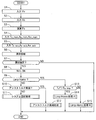
- FIG. 8 is a flowchart showing the flow of processing performed in the electronic control unit 7 when the sensor is abnormal. The following processing is repeated every predetermined time while the ignition switch is on.
- step S1 the vehicle speed Vv is input, and the process proceeds to step S2.
- step S2 the steering speed Vs is input, and the process proceeds to step S3.
- the steering speed Vs is obtained from the steering angle signal.
- step S3 the steering frequency Fs is calculated, and the process proceeds to step S4.
- step S4 the steering torque signal Ts_main from the main steering torque sensor 4a, the steering angle signal As_main from the main steering angle sensor 5a, and the motor rotation angle signal Am_main from the main motor rotation angle sensor 6a are input, and the process proceeds to step S5. .
- step S5 the steering torque signal Ts_sub from the sub steering torque sensor 4b, the steering angle signal As_sub from the sub steering angle sensor 5b, and the motor rotation angle signal Am_sub from the sub motor rotation angle sensor 6b are input, and the process proceeds to step S6.
- step S6 abnormality diagnosis of each sensor is performed, and the process proceeds to step S7.
- step S7 it is determined whether or not an abnormality of any sensor is confirmed. When the abnormality is confirmed, the process proceeds to step S8, and when the abnormality is not confirmed, the process is terminated.
- the determination of the abnormality of each sensor is determined when the state where the abnormality has occurred in the sensor (the state where the abnormality is detected) continues for a predetermined time.
- step S8 the warning lamp 102 is turned on and the process proceeds to step S9.
- step S9 it is determined whether to perform Limp Home processing. When the Limp Home process is performed, the process proceeds to Step S13, and when the Limp Home process is not performed, the process proceeds to Step S10.
- step S10 it is determined whether to perform assist torque gradual reduction processing.
- the process proceeds to step S12, and when the assist torque gradual decrease process is not performed, the process proceeds to step S11.
- step S11 the system of the power steering device 1 is shut off and the process shifts to manual steering. Manual steering indicates a state in which the assist torque from the power steering device 1 is not applied.
- step S12 an assist torque gradual reduction process is performed, and the process ends.
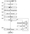
- step S13 it is determined whether or not the target assist torque Ta * is larger than the assist torque upper limit value Ta_limp at the time of Limp Home.
- the process proceeds to step S14.
- the process proceeds to step S15.
- the assist torque upper limit value Ta_limp may be set as appropriate. However, the assist torque upper limit value Ta_limp is set to a value smaller than the assist torque upper limit value Ta_limit during normal control (when the sensor is normal).
- step S14 Limp Home processing A is performed, and the processing is terminated.
- step S15 the Limp Home process B is performed and the process is terminated.
- FIG. 9 is a flowchart showing a flow of assist torque gradual reduction processing performed in step S12 of FIG.
- the assist torque upper limit value Ta_limit is set to the target assist torque Ta *, and the process proceeds to step S22.
- the limiter setting unit 99 sets the control current for controlling the electric motor 40 so that the assist torque becomes the assist torque upper limit value Ta_limit as the limiter 90e upper limit value.
- the gradual decrease time ⁇ t is calculated, and the process proceeds to step S23. The calculation is performed such that the gradually decreasing time ⁇ t becomes longer as the vehicle speed is higher, the steering frequency is higher, and the steering torque is higher.
- step S23 the upper limit value reduction rate ⁇ T is set by the following equation, and the process proceeds to step S24.
- ⁇ T Ta_limit / ⁇ t
- step S24 the gain reduction rate ⁇ G is set by the following equation, and the process proceeds to step S25.
- ⁇ G (1 ⁇ G1) / ⁇ t
- G1 is a predetermined value equal to or less than 1, which is determined in advance.
- step S25 the assist torque upper limit value Ta_limit is set by the following equation, and the process proceeds to step S26.
- Ta_limit Ta_limit- ⁇ T
- step S26 the gain G is set by the following equation, and the process proceeds to step S27.
- G G ⁇ G
- the initial value of the gain G before the assist torque gradual reduction processing is 1 is 1.
- step S27 it is determined whether or not the assist torque upper limit value Ta_limit is smaller than Ta1.
- the process proceeds to step S28.
- the assist torque upper limit value Ta_limit is equal to or greater than Ta1, the process returns to step S25.
- Ta1 is a predetermined value determined in advance to determine that the assist torque upper limit value Ta_limit has become a sufficiently small value.
- step S28 the assist torque upper limit value Ta_limit is set to zero, and the process proceeds to step S29.
- step S29 the gain G is set to zero and the process ends.
- FIG. 10 is a flowchart showing the flow of the Limp Home process A performed in step S14 of FIG.
- the assist torque upper limit value Ta_limit is set to the target assist torque Ta *, and the process proceeds to step S32.
- the limiter setting unit 99 sets the control current for controlling the electric motor 40 so that the assist torque becomes the assist torque upper limit value Ta_limit as the limiter 90e upper limit value.
- a gradual decrease time ⁇ t is calculated, and the process proceeds to step S33. The calculation is performed such that the gradually decreasing time ⁇ t becomes longer as the vehicle speed is higher, the steering frequency is higher, and the steering torque is higher.
- step S33 the upper limit value reduction rate ⁇ T is set by the following equation, and the process proceeds to step S24.
- ⁇ T (Ta_limit-Ta_limp) / ⁇ t
- step S34 the gain reduction rate ⁇ G is set by the following equation, and the process proceeds to step S35.
- ⁇ G (1 ⁇ G1) / ⁇ t
- G1 is a predetermined value equal to or less than 1, which is determined in advance.
- step S35 the counter threshold C1 is set according to the gradual decrease time ⁇ t, and the process proceeds to step S36.
- the counter threshold C1 is set to the number of times that the processing of steps S36 to S39 described later can be performed within the gradual decrease time ⁇ t.
- step S36 it is determined whether or not the counter C is larger than the counter threshold C1. When the counter C is larger than the counter threshold C1, the process proceeds to step S40. When the counter C is equal to or less than the counter threshold C1, the process proceeds to step S37.
- step S37 the assist torque upper limit value Ta_limit is set by the following equation, and the process proceeds to step S28.
- Ta_limit Ta_limit- ⁇ T
- the gain G is set by the following equation, and the process proceeds to step S39.
- G G ⁇ G
- the initial value of the gain G before the Limp Home process A is performed is 1.
- the counter C is incremented, and the process returns to step S36.
- the assist torque upper limit value Ta_limit is set to the assist torque upper limit value Ta_limp during Limp Home, and the process ends.
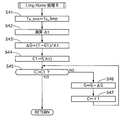
- FIG. 11 is a flowchart showing the flow of the Limp Home process B performed in step S15 of FIG.
- the assist torque upper limit value Ta_limit is set to the assist torque upper limit value Ta_limp during Limp Home, and the process proceeds to step S42.
- the limiter setting unit 99 sets the control current for controlling the electric motor 40 so that the assist torque becomes the assist torque upper limit value Ta_limit as the limiter 90e upper limit value.
- a gradual decrease time ⁇ t is calculated, and the process proceeds to step S43. The calculation is performed such that the gradually decreasing time ⁇ t becomes longer as the vehicle speed is higher, the steering frequency is higher, and the steering torque is higher.
- the gain reduction rate ⁇ G is set by the following equation, and the process proceeds to step S44.
- ⁇ G (1 ⁇ G1) / ⁇ t
- G1 is a predetermined value equal to or less than 1, which is determined in advance.
- step S44 the counter threshold C1 is set according to the gradual decrease time ⁇ t, and the process proceeds to step S35.
- the counter threshold C1 is set to the number of times that the processing of steps S45 to S47 described later can be performed within the gradual decrease time ⁇ t.
- step S45 it is determined whether or not the counter C is greater than the counter threshold C1. When the counter C is greater than the counter threshold C1, the process is terminated. When the counter C is equal to or smaller than the counter threshold C1, the process proceeds to step S46.
- step S47 the counter C is incremented, and the process returns to step S45.
- the assist torque gradually decreasing process is a control for gradually decreasing the assist torque and finally setting the assist torque to zero.
- the assist torque gradual reduction treatment is performed, for example, when an abnormality occurs in the steering angle sensor 5.
- the electronic control unit 7 of the first embodiment does not have a function of calculating an alternative steering angle signal when an abnormality occurs in the steering angle sensor 5. Therefore, if an abnormality occurs in the steering angle sensor 5, there is a possibility that an appropriate assist torque cannot be applied, and the assist torque is finally made zero. However, if the assist torque is rapidly reduced, the driver's steering may be affected.
- the steering angle signal is used only for calculating the assist torque when the steering wheel is steered in the return direction. For these reasons, although the steering feeling when the steering wheel is steered in the return direction is deteriorated, the influence on the driver's steering is suppressed by gradually decreasing the assist torque.
- FIG. 12 is a time chart of the assist torque upper limit Ta_limit and the gain G during the assist torque gradual reduction process.
- the upper time chart shows the assist torque upper limit value Ta_limit, and the lower time chart shows the gain G.
- the assist torque upper limit value Ta_limit indicates the assist torque when the electric motor 40 is controlled with the upper limit value of the motor command current at the limit 90e set by the limiter setting unit 99.
- the gain G is a numerical value of the gain G in the gain 90b set by the characteristic information correction unit 98.
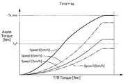
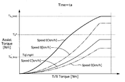
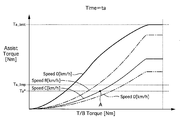
- FIG. 13 is a graph showing the relationship between the steering torque (torsion bar torque) and the target assist torque at time ta. As described above, since the target assist torque and the motor command current have a high correlation and are approximately proportional, this graph may be handled as a target assist torque map substantially equivalent to the motor command current map 90a. Further, the steering torque coincides with the steering reaction force in the steering wheel.
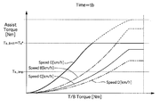
- FIG. 14 is a target assist torque map at time tb.
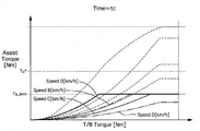
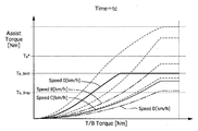
- FIG. 15 is a target assist torque map at time tc.
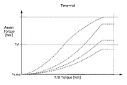
- FIG. 16 is a target assist torque map at time td.
- time tb When sensor abnormality is confirmed
- the assist torque upper limit value Ta_limit is set to the current target assist torque Ta *.
- the gain G is set to 1 at the time tb.
- the assist torque upper limit value Ta_limit decreases at a stretch to the current target assist torque Ta *, but the output assist torque itself does not change, and thus does not affect the driver's steering.
- the assist torque upper limit value Ta_limit is gradually decreased.
- the assist torque upper limit value Ta_limit is gradually decreased linearly. That is, the assist torque upper limit value Ta_limit is decreased with a constant decrease rate.
- the gain G is gradually reduced.
- the gain G is gradually decreased linearly. That is, the gain G is reduced with a constant decrease rate. Since the assist torque upper limit value Ta_limit gradually decreases, even if the driver keeps the steering state (steering torque and vehicle speed) at time tb constant, the assist torque gradually decreases. Therefore, the driver feels that the steering load gradually increases.
- the driver can recognize that some abnormality has occurred in the power steering apparatus 1. Further, since the assist torque gradually decreases, the influence on the driver's steering due to the decrease of the assist torque can be suppressed.
- the gain G is decreased, the gradient of the target assist torque with respect to the steering torque is reduced in the target assist torque map (FIG. 15). For this reason, when the driver returns the steering wheel to neutral and turns the wheel again, the driver feels that the steering load has increased compared to the previous steering. Thereby, the driver can recognize that some abnormality has occurred in the power steering apparatus 1. Further, since the gain G gradually decreases, the influence on the driver's steering due to the decrease of the assist torque can be suppressed.
- the Limp Home process A is a control that allows the assist torque to be output to some extent although the assist torque is reduced.
- the Limp Home process A is performed, for example, when an abnormality occurs in the steering torque sensor 4 or the motor rotation angle sensor 6.
- the electronic control unit 7 calculates an alternative steering torque signal or an alternative motor rotation angle signal when an abnormality occurs in the steering torque sensor 4 or the motor rotation angle sensor 6.
- the steering feeling of the driver is slightly worsened, but the assist torque is appropriately adjusted. It can be granted.
- the assist torque is continuously applied as it is, the driver may not be able to recognize that an abnormality has occurred in the power steering device 1. Therefore, the control is continued while limiting the magnitude of the assist torque to be applied.
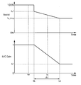
- FIG. 17 is a time chart of the assist torque upper limit Ta_limit and the gain G during the Limp Home process A.
- the upper time chart shows the assist torque upper limit value Ta_limit, and the lower time chart shows the gain G.
- FIG. 18 is a target assist torque map at time ta.
- FIG. 19 is a target assist torque map at time tb.
- FIG. 20 is a target assist torque map at time tc.
- FIG. 21 is a target assist torque map at time td.
- time tb When sensor abnormality is confirmed
- the assist torque upper limit value Ta_limit is set to the current target assist torque Ta *.
- the gain G is set to 1 at the time tb.
- the assist torque upper limit value Ta_limit decreases at a stretch to the current target assist torque Ta *, but the output assist torque itself does not change, and thus does not affect the driver's steering.
- the assist torque upper limit value Ta_limit is gradually decreased.
- the assist torque upper limit value Ta_limit is gradually decreased linearly.
- the gain G is gradually reduced. Since the assist torque upper limit value Ta_limit gradually decreases, even if the driver keeps the steering state (steering torque and vehicle speed) at time tb constant, the assist torque gradually decreases. Therefore, the driver feels that the steering load gradually increases. Thereby, the driver can recognize that some abnormality has occurred in the power steering apparatus 1. Further, since the assist torque gradually decreases, the influence on the driver's steering due to the decrease of the assist torque can be suppressed.
- the gain G When the gain G is decreased, the gradient of the target assist torque with respect to the steering torque is reduced in the target assist torque map (FIG. 20). Therefore, when the driver returns the steering wheel to neutral and turns the wheel again, the driver feels that the steering load has increased compared to the previous steering. Thereby, the driver can recognize that some abnormality has occurred in the power steering apparatus 1. Further, since the gain G gradually decreases, the influence on the driver's steering due to the decrease of the assist torque can be suppressed.
- the assist torque upper limit value Ta_limit is set to the assist torque upper limit value Ta_limp at Limp Home.
- Gain G is set to G1.
- the Limp Home process B is a control that allows the assist torque to be output to some extent, although the assist torque is reduced similarly to the Limp Home process A.
- the Limp Home process B is performed, for example, when an abnormality occurs in the steering torque sensor 4 or the motor rotation angle sensor 6.
- the assist torque upper limit value Ta_limit is set to the target assist torque Ta * and then gradually decreased to the assist torque upper limit value Ta_limp. This is a process for suppressing the influence on the driver's steering because the Limp Home process A is performed when the target assist torque Ta * at the time of sensor abnormality determination is larger than the assist torque upper limit value Ta_limp.
- the Limp Home process B is performed when the target assist torque Ta * at the time of sensor abnormality determination is smaller than the assist torque upper limit value Ta_limp. Therefore, when the sensor abnormality is confirmed, the assist torque upper limit value Ta_limit is reduced to the assist torque upper limit value Ta_limp all at once.
- FIG. 22 is a time chart of the assist torque upper limit Ta_limit and the gain G during the Limp Home process B.
- the upper time chart shows the assist torque upper limit value Ta_limit, and the lower time chart shows the gain G.
- FIG. 23 is a target assist torque map at time ta.
- FIG. 24 is a target assist torque map at time tb.
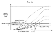
- FIG. 25 is a target assist torque map at time tc.
- FIG. 26 is a target assist torque map at time td.
- the assist torque upper limit value Ta_limit is set to the assist torque upper limit value Ta_limp.
- the gain G is set to 1 at the time tb.
- time tc When assist torque gradually decreases
- the assist torque upper limit value Ta_limit is maintained at the assist torque upper limit value Ta_limp.
- the gain G is gradually reduced.
- the gain G is decreased, the gradient of the target assist torque with respect to the steering torque is reduced in the target assist torque map (FIG. 25). Therefore, when the driver returns the steering wheel to neutral and turns the wheel again, the driver feels that the steering load has increased compared to the previous steering. Thereby, the driver can recognize that some abnormality has occurred in the power steering apparatus 1. Further, since the gain G gradually decreases, the influence on the driver's steering due to the decrease of the assist torque can be suppressed.
- the target assist torque Ta * is controlled to be constant from time ta to time td.
- the control point on the target assist torque map was point A at time ta and time tb (FIGS. 23 and 24) before gain G was reduced.
- the gain G starts to decrease, and the control point moves to point B at time tc (FIG. 25). Further, the gain G becomes smaller, and the control point moves to point C at time td (FIG. 26). It can be seen that as the control point moves from point A ⁇ point B ⁇ point C, the steering torque increases, and the ratio of the steering torque to the assist torque increases. In other words, even if the steering wheel is kept being steered, by reducing the gain G, the driver feels that the steering load increases.
- the target assist torque Ta * is small when the steering load is low (when the steering torque is small).
- the assist torque upper limit value Ta_limit is gradually decreased, first, the target assist torque Ta * in the high steering load region is limited, and the target assist torque Ta * in the low steering load region is also limited with time. That is, in the low steering load region, the driver cannot feel an increase in the steering load, or it takes time until the driver feels an increase in the steering load. For this reason, the driver may not be able to recognize that an abnormality has occurred in the power steering apparatus 1, or may take time to recognize it.
- the assist torque upper limit value Ta_limit becomes a smaller value, and finally the assist torque upper limit value Ta_limit becomes zero.
- the driver's steering is in the low steering load region, the driver may feel that the assist torque has suddenly decreased and the steering load has suddenly increased.
- the target assist torque Ta * can be reduced regardless of the driver's steering status (regardless of the current steering load). Therefore, it is possible to make the driver recognize the increase in the steering load immediately after the abnormality of the power steering device 1 occurs.
- the electronic control unit 7 (control device) of the power steering device 1 that applies a steering force (assist torque) by the electric motor 40 to the steering mechanism 2 that steers the steered wheels according to the steering operation of the steering wheel
- a main steering torque signal receiving unit 7b torque signal receiving unit
- a command signal motor command current
- a fail safe processing unit 97 (assist limit command signal receiving unit) for receiving the assist limit command signal;
- the characteristic information correction unit 98 for correcting the characteristic information so that the command signal corresponding to the steering torque gradually decreases, and the electric motor for the electric motor based on the command signal.
- the electronic control unit 7 includes a limiter setting unit 99 (upper limit setting unit) for setting an upper limit value of the command signal.
- the limiter setting unit 99 is associated with reception of the assist limit command signal by the failsafe processing unit 97.
- the upper limit value of the command signal is gradually decreased. Therefore, by gradually decreasing the upper limit value of the command signal, the driver can feel an increase in the steering load even in the high steering load region. Therefore, it is possible to make the driver recognize the assist limitation even in the high steering load region.
- the characteristic information correction unit 98 corrects the map by changing the gain applied to the map (characteristic information) in the motor command current map 90a. Therefore, the map can be corrected while suppressing an increase in the amount of map data in the motor command current map 90a.
- the characteristic information correction unit 98 corrects the motor current command value by applying a gain to the motor current command value (command signal) calculated according to the map (characteristic information) in the motor command current map 90a. I tried to do it. Since a gain is applied to the motor current command value output from the motor command current map 90a, an increase in calculation load can be suppressed as compared with a case where the entire map in the motor command current map 90a is corrected.
- the electronic control unit 7 includes a limiter setting unit 99 (upper limit setting unit) for setting the upper limit value of the command signal.
- the limiter setting unit 99 sets the upper limit value to the same value as the command signal when the fail safe processing unit 97 receives the assist restriction command signal. Therefore, the steering load increases immediately after the assist limitation is performed, and the driver can recognize the assist limitation.
- the electronic control unit 7 outputs a signal for turning on the warning lamp 102 mounted on the vehicle when the fail-safe processing unit 97 receives the assist restriction signal. Therefore, in addition to indirect assist limitation notification due to an increase in steering load, direct assist limitation notification due to lighting of the warning lamp 102 can be performed.
- the inverter circuit 76 includes a supply power limiting unit 100 that sets an upper limit value for the power supplied to the electric motor 40.
- the drive power for driving the electric motor is supplied to the electric motor 40 based on the smaller one of the set upper limit value and the command signal corrected by the characteristic information correction unit 98.
- the characteristic information correction unit 98 when the assist limitation by the supply power limitation unit 100 is applied, by selecting the smaller command signal among the command signals corrected by the upper limit values of both, the power steering device The safety of assist control 1 can be improved.
- the characteristic information correction unit 98 is configured to gradually decrease the characteristic information. Therefore, the steering load can be increased smoothly, and the uncomfortable feeling of steering feeling due to the increase in steering load can be suppressed.
- the electronic control unit 7 includes a CAN communication circuit 71 that receives a vehicle speed signal.
- the characteristic information correction unit 98 increases the time for correcting characteristic information (gradual decrease time ⁇ t) as the vehicle speed increases. I made it. The higher the vehicle speed, the greater the influence on the driver's steering due to the change in the steering reaction force. Therefore, by increasing the gradual decrease time ⁇ t as the vehicle speed increases, the influence on the driver's steering can be suppressed, and the safety in vehicle travel can be improved.
- the electronic control unit 7 includes a steering frequency signal calculation unit 103 (steering frequency signal receiving unit) that receives a signal related to the frequency of the steering operation, and the characteristic information correction unit 98 corrects the characteristic information as the steering frequency increases.
- the time to perform was lengthened. The higher the frequency of the steering operation, the greater the influence on the driver's steering due to the change in the steering reaction force. Therefore, by increasing the gradual decrease time ⁇ t as the frequency of the steering operation is higher, the influence on the steering of the driver can be suppressed, and the safety in traveling the vehicle can be improved.
- the characteristic information correction unit 98 increases the characteristic information correction time (gradual decrease time ⁇ t) as the steering torque increases.
- the greater the steering torque the greater the influence on the driver's steering due to the change in the steering reaction force. Therefore, by increasing the gradual decrease time ⁇ t, it is possible to suppress the influence on the steering of the driver and improve the safety in traveling the vehicle.
- Steering mechanism 2 that steers the steered wheels according to the steering operation of the steering wheel, an electric motor 40 that applies steering force to the steering mechanism 2, and an electronic control unit 7 (controller) that controls the driving of the electric motor;
- a main steering torque signal receiving unit 7b torque signal receiving unit that is provided in the electronic control unit 7 and receives a steering torque signal generated in the steering mechanism 2;
- Arithmetic unit and an electronic control unit 7 and an assist limit command signal for reducing the power supplied to the electric motor 40.
- the fail-safe processing unit 97 (assist limit command signal receiving unit) to be received and the electronic control unit 7 are provided, and the command signal corresponding to the steering torque gradually decreases as the fail-safe processing unit 97 receives the assist limit command signal.
- a motor control circuit 7g and an inverter circuit 76 (driving) that are provided in the electronic information control unit 7 for correcting the characteristic information and supply driving power for driving the electric motor to the electric motor based on the command signal. Power supply unit). Therefore, as the command signal (motor command current) gradually decreases, the assist torque gradually decreases, and the driver can feel that the steering reaction force gradually increases regardless of the steering situation. This allows the driver to recognize the assist restriction even immediately after receiving the assist restriction command signal in the fail safe processing unit 97. Therefore, it is possible to suppress a sense of discomfort given to the driver when assist is limited.
- the present invention has been described based on the first embodiment.
- the specific configuration of each invention is not limited to the first embodiment, and even if there is a design change or the like without departing from the gist of the present invention.
- any combination or omission of each constituent element described in the claims and the specification is possible within a range where at least a part of the above-described problems can be solved or a range where at least a part of the effect is achieved. It is.
- the motor command current is calculated by the motor command current calculation unit 90 in the electronic control unit 7, and the electric motor 40 is controlled by the motor control circuit 7g and the inverter circuit 76 based on the motor command current.
- the target assist torque may be calculated on the electronic control unit 7 side, and the electric motor 40 may be controlled by the motor control circuit 7g and the inverter circuit 76 based on the calculated target assist torque.
- the assist torque upper limit value Ta_limit is set in the process performed in the electronic control unit 7 when the sensor is abnormal as shown in FIG. 8, but the upper limit value of the motor command current corresponding to the assist torque upper limit value Ta_limit is You may make it set.
- the assist torque upper limit value Ta_limit is set to the target assist torque Ta * in step S21 of the assist torque gradual reduction process (FIG. 9) and step S31 of the Limp Home process A (FIG. 10).
- the actual assist torque that is generated may be set.
- the fail-safe processing unit 97 determines a process to be selected according to a sensor in which an abnormality has occurred.
- the assist torque gradual reduction process is selected when an abnormality occurs in the steering angle sensor 5, and the Limp Home control is selected when an abnormality occurs in the steering torque sensor 4 or the motor rotation angle sensor 6.
- the assist torque gradual reduction process may be selected when an abnormality occurs in a sensor other than the steering angle sensor 5, or when an abnormality occurs in a sensor other than the steering torque sensor 4 and the motor rotation angle sensor 6, Limp You may make it select Home control.
- the selection of each control may be selected based on an abnormality of another configuration instead of an abnormality of the sensor.
- a control device for a power steering device that applies a steering force by an electric motor to a steering mechanism that steers steered wheels according to a steering operation of a steering wheel.
- a torque signal receiver for receiving a steering torque signal generated in the steering mechanism;
- a calculation unit that calculates a command signal for driving and controlling the electric motor based on the steering torque signal, the command signal calculation unit having characteristic information that increases the command signal as the steering torque increases;
- An assist limit command signal receiving unit for receiving an assist limit command signal for reducing the power supplied to the electric motor;
- a characteristic information correction unit that corrects the characteristic information so that the command signal corresponding to the steering torque gradually decreases with the reception of the assist limit command signal by the assist limit signal reception unit;
- a driving power supply unit that supplies driving power for driving the electric motor to the electric motor based on the command signal.
- the driver can feel that the steering reaction force gradually increases regardless of the steering situation. Therefore, even if it is immediately after receiving an assist restriction command signal in an assist restriction command signal receiving part, a driver can be made to recognize assistance restriction. Therefore, it is possible to suppress a sense of discomfort given to the driver when assist is limited.
- control device of the power steering apparatus includes an upper limit value setting unit that sets an upper limit value of the command signal,
- the upper limit value setting unit gradually decreases the upper limit value of the command signal with the reception of the assist limit command signal by the assist limit signal receiving unit. Therefore, by gradually decreasing the upper limit value of the command signal, the driver can feel an increase in the steering load even in the high steering load region. Therefore, it is possible to make the driver recognize the assist limitation even in the high steering load region.
- the characteristic information correction unit corrects the characteristic information by changing a gain applied to the characteristic information. Therefore, the map can be corrected while suppressing an increase in the data amount of the characteristic information.
- the characteristic information correction unit corrects the command signal by applying the gain to the command signal calculated according to the characteristic information. Since a gain is applied to the command signal, an increase in calculation load can be suppressed as compared with a case where characteristic information is corrected.
- control device of the power steering apparatus includes an upper limit value setting unit that sets an upper limit value of the command signal,
- the upper limit setting unit sets the upper limit to the same value as the command signal when the assist limit signal receiving unit receives the assist limit command signal. Therefore, the steering load increases immediately after the assist limitation is performed, and the driver can recognize the assist limitation.
- a signal for turning on a warning lamp mounted on the vehicle is output in accordance with the reception of the assist restriction signal by the assist restriction signal receiver. Therefore, in addition to indirect assist limitation notification due to an increase in steering load, direct assist limitation notification due to lighting of a warning lamp can be performed.
- control device for the power steering apparatus includes a supply power limiting unit that sets an upper limit value for the power supplied to the electric motor when the assist limit signal is received by the assist limit signal receiving unit.
- the drive power supply unit drives the electric motor with respect to the electric motor based on a smaller one of the upper limit value set by the supply power limit unit and the command signal corrected by the characteristic information correction unit. Supply drive power.
- the assist command of the power steering device is selected by selecting the smaller command signal among the command signals corrected by the upper limit values of both. Control safety can be improved.
- the characteristic information correcting unit corrects the characteristic information by linearly decreasing the characteristic information. Therefore, the steering load can be increased smoothly, and the uncomfortable feeling of steering feeling due to the increase in steering load can be suppressed.
- control device of the power steering apparatus includes a vehicle speed signal receiving unit that receives a vehicle speed signal
- the characteristic information correction unit increases the time for correcting the characteristic information as the vehicle speed increases.
- the higher the vehicle speed the greater the influence on the driver's steering due to the change in the steering reaction force. Therefore, by increasing the time for correcting the characteristic information as the vehicle speed increases, the influence on the driver's steering can be suppressed, and the safety in driving the vehicle can be improved.
- control device of the power steering apparatus includes a steering frequency signal receiving unit that receives a signal related to the frequency of the steering operation,
- the characteristic information correction unit increases the time for correcting the characteristic information as the steering frequency increases.
- the higher the steering frequency the greater the influence on the driver's steering due to the change in the steering reaction force. Therefore, the longer the steering frequency, the longer the time for correcting the characteristic information, thereby suppressing the influence on the driver's steering and improving the safety in driving the vehicle.
- the characteristic information correction unit increases the time for correcting the characteristic information as the steering torque increases.
- the greater the steering torque the greater the influence on the driver's steering due to the change in the steering reaction force. Therefore, as the steering torque is increased, the time for correcting the characteristic information is lengthened, so that the influence on the driver's steering can be suppressed, and the safety in driving the vehicle can be improved.
- the power steering device A steering mechanism for turning the steered wheels according to the steering operation of the steering wheel; An electric motor for applying a steering force to the steering mechanism; A controller for driving and controlling the electric motor; A torque signal receiving unit provided in the controller for receiving a steering torque signal generated in the steering mechanism; A calculation unit that is provided in the controller and calculates a command signal for driving and controlling the electric motor based on the steering torque signal, and has characteristic information that increases the command signal as the steering torque increases.
- a command signal calculation unit An assist limit command signal receiving unit provided in the controller for receiving an assist limit command signal for reducing the power supplied to the electric motor;
- a characteristic information correction unit that is provided in the controller and corrects the characteristic information so that the command signal corresponding to the steering torque is gradually decreased in accordance with reception of the assist limit command signal by the assist limit signal reception unit;
- a drive power supply unit that is provided in the controller and supplies drive power for driving the electric motor to the electric motor based on the command signal. Therefore, by gradually decreasing the command signal, the driver can feel that the steering reaction force gradually increases regardless of the steering situation. Thereby, even if it is immediately after receiving an assist restriction command signal in an assist restriction command signal receiving part, a driver can be made to recognize assistance restriction. Therefore, it is possible to suppress a sense of discomfort given to the driver when assist is limited.
- the controller includes an upper limit setting unit that sets an upper limit of the command signal,
- the upper limit value setting unit gradually decreases the upper limit value of the command signal with the reception of the assist limit command signal by the assist limit signal receiving unit. Therefore, by gradually decreasing the upper limit value of the command signal, the driver can feel an increase in the steering load even in the high steering load region. Therefore, it is possible to make the driver recognize the assist limitation even in the high steering load region.
- the characteristic information correction unit corrects the characteristic information by changing a gain applied to the characteristic information. Therefore, the map can be corrected while suppressing an increase in the data amount of the characteristic information.
- the characteristic information correction unit corrects the command signal by applying the gain to the command signal calculated according to the characteristic information. Since a gain is applied to the command signal, an increase in calculation load can be suppressed as compared with a case where characteristic information is corrected.
- the controller includes an upper limit setting unit that sets an upper limit of the command signal, The upper limit setting unit sets the upper limit to the same value as the command signal when the assist limit signal receiving unit receives the assist limit command signal. Therefore, the steering load increases immediately after the assist limitation is performed, and the driver can recognize the assist limitation.
- the controller outputs a signal for turning on a warning lamp mounted on the vehicle when the assist limit signal receiving unit receives the assist limit signal. Therefore, in addition to indirect assist limitation notification due to an increase in steering load, direct assist limitation notification due to lighting of a warning lamp can be performed.
- the controller includes a supply power limiting unit that sets an upper limit value for the power supplied to the electric motor in accordance with reception of the assist limit signal by the assist limit signal receiving unit.
- the drive power supply unit drives the electric motor with respect to the electric motor based on a smaller one of the upper limit value set by the supply power limit unit and the command signal corrected by the characteristic information correction unit. Supply drive power.
- the assist command of the power steering device is selected by selecting the smaller command signal among the command signals corrected by the upper limit values of both. Control safety can be improved.
- the characteristic information correction unit corrects the characteristic information by linearly decreasing the characteristic information. Therefore, the steering load can be increased smoothly, and the uncomfortable feeling of steering feeling due to the increase in steering load can be suppressed.
- the controller includes a vehicle speed signal receiving unit that receives a vehicle speed signal
- the characteristic information correction unit increases the time for correcting the characteristic information as the vehicle speed increases.
- the higher the vehicle speed the greater the influence on the driver's steering due to the change in the steering reaction force. Therefore, by increasing the time for correcting the characteristic information as the vehicle speed increases, the influence on the driver's steering can be suppressed, and the safety in driving the vehicle can be improved.
Landscapes
- Engineering & Computer Science (AREA)
- Chemical & Material Sciences (AREA)
- Combustion & Propulsion (AREA)
- Transportation (AREA)
- Mechanical Engineering (AREA)
- Steering Control In Accordance With Driving Conditions (AREA)
- Power Steering Mechanism (AREA)
Abstract
操舵力を付与する電動モータに供給される電力を低減させるアシスト制限を行う際に、運転者が感じる操舵反力をアシスト制限開始後から徐々に増大させることができるパワーステアリング装置の制御装置およびパワーステアリング装置を提供すること。 電動モータによって操舵機構に操舵力を付与するパワーステアリング装置の制御装置は、操舵トルクが増大するほど、電動モータを駆動制御するための指令信号を増大させる特性情報を有する指令信号演算部と、アシスト制限指令信号の受信に伴い、指令信号が漸減するように特性情報を補正する特性情報補正部と、指令信号に基づき電動モータに駆動電力を供給する駆動電力供給部と、を備える。
Description
本発明は、パワーステアリング装置の制御装置およびパワーステアリング装置に関する。
この種の技術としては、下記の特許文献1に記載の技術が開示されている。特許文献1には、システムに異常が生じた箇所に応じてパワーステアリング装置により付与するアシストトルクを制限するアシストリミットを設定するものが開示されている。
特許文献1の技術では、アシストリミットによりアシストトルクの上限値を制限している。通常走行時には付与するアシストトルクは比較的小さく、アシストリミットにより制限した上限値まで達しないことがある。このとき運転者は通常通り操舵でき、システムに異常が発生していることを認識することができない。
システムの異常箇所が増えるとアシストリミットはよりアシストトルクを制限するように設定される。アシストトルクの制限が大きくなれば、通常走行時においてもアシストトルクがアシストリミットにより制限した上限値までするため、運転者は操舵反力が増大したと感じることができ、システムに異常が発生していると認識することができる。しかし、運転者は急に操舵反力が増大したと感じるため、操舵への影響が大きい。
本発明の目的とするところは、操舵力を付与する電動モータに供給される電力を低減させるアシスト制限を行う際に、運転者が感じる操舵反力をアシスト制限開始後から徐々に増大させることができるパワーステアリング装置の制御装置およびパワーステアリング装置を提供することである。
上記目的を達成するため、本発明の第1実施形態では、電動モータによって操舵機構に操舵力を付与するパワーステアリング装置の制御装置は、操舵トルクが増大するほど、電動モータを駆動制御するための指令信号を増大させる特性情報を有する指令信号演算部と、アシスト制限指令信号の受信に伴い、指令信号が漸減するように特性情報を補正する特性情報補正部と、指令信号に基づき電動モータに駆動電力を供給する駆動電力供給部と、を備える。
第2実施形態では、電動モータによって操舵機構に操舵力を付与するパワーステアリング装置は、コントローラを備える。コントローラは、操舵トルクが増大するほど、電動モータを駆動制御するための指令信号を増大させる特性情報を有する指令信号演算部と、アシスト制限指令信号の受信に伴い、指令信号が漸減するように特性情報を補正する特性情報補正部と、指令信号に基づき電動モータに駆動電力を供給する駆動電力供給部と、を備える。
第2実施形態では、電動モータによって操舵機構に操舵力を付与するパワーステアリング装置は、コントローラを備える。コントローラは、操舵トルクが増大するほど、電動モータを駆動制御するための指令信号を増大させる特性情報を有する指令信号演算部と、アシスト制限指令信号の受信に伴い、指令信号が漸減するように特性情報を補正する特性情報補正部と、指令信号に基づき電動モータに駆動電力を供給する駆動電力供給部と、を備える。
よって、運転者が感じる操舵反力をアシスト制限開始後から徐々に増大させることができる。
[実施例1]
実施例1のパワーステアリング装置1について説明する。実施例1のパワーステアリング装置1は、電動モータ40の駆動力をボールねじ機構26を介して転舵軸10に伝達することで運転者の操舵による操舵トルクに対してアシストトルクを付与するものである(アシスト制御)。
〔パワーステアリング装置の構成〕
図1はパワーステアリング装置1の斜視図である。図2はパワーステアリング装置1を転舵軸10の軸線上で切断した断面図である。
パワーステアリング装置1は、運転者が操舵したステアリングホイールの回転を、転舵輪を転舵させる転舵軸10に伝達する操舵機構2と、転舵軸10にトルクを付与するアシスト機構3とを有している。
パワーステアリング装置1の各構成要素は、第1ハウジング31、第2ハウジング32およびモータハウジング33からなるハウジング30内に収容されている。
操舵機構2は、ステアリングホイールに連結する操舵入力軸80を有している。操舵入力軸80の先端にはピニオン81が形成されている。ピニオン81は、転舵軸10の外周に形成されたラックと噛み合っている。
アシスト機構3は、電動モータ40と、電動モータ40の出力を転舵軸10に伝達するボールねじ機構26とを有している。電動モータ40は、運転者によりステアリングホイールに入力された操舵トルクおよび操舵量に応じて電子コントロールユニット7(図4,5,6)より出力が制御されている。
ボールねじ機構26は、ナット20と出力プーリ27とを有している。出力プーリ27の外見は円筒状の部材であって、ナット20に一体回転可能に固定されている。電動モータ40の駆動軸40aには円筒状の入力プーリ35が一体に回転するように固定されている。ナット20の回転軸を第1基準軸線L1とし、入力プーリ35の回転軸を第2基準軸線L2とする。第2基準軸線L2は、第1基準軸線L1に対して径方向にオフセットするように配置される。なお、ナット20に一体に固定されている出力プーリ27も第1基準軸線L1を回転軸としている。
ボールねじ機構26は、ナット20と出力プーリ27とを有している。出力プーリ27の外見は円筒状の部材であって、ナット20に一体回転可能に固定されている。電動モータ40の駆動軸40aには円筒状の入力プーリ35が一体に回転するように固定されている。ナット20の回転軸を第1基準軸線L1とし、入力プーリ35の回転軸を第2基準軸線L2とする。第2基準軸線L2は、第1基準軸線L1に対して径方向にオフセットするように配置される。なお、ナット20に一体に固定されている出力プーリ27も第1基準軸線L1を回転軸としている。
入力プーリ35と出力プーリ27との間にはベルト28が巻回されている。ベルト28は樹脂によって形成されている。電動モータ40の駆動力は入力プーリ35、ベルト28、出力プーリ27を介してナット20に伝達される。入力プーリ35の外径は出力プーリ27の外径より小さく形成されている。入力プーリ35、出力プーリ27およびベルト28によって減速器が構成されている。
ナット20は、転舵軸10を包囲するように円筒状に形成され、転舵軸10に対し回転自在に設けられている。ナット20の内周には、螺旋状に溝が形成されており、この溝がナット側ボールねじ溝21を構成している。転舵軸10の外周にはラックが形成されている部分とは軸方向に離れた位置に螺旋状の溝が形成されており、この溝が転舵軸側ボールねじ溝11を構成している。
転舵軸10にナット20を挿入した状態で、ナット側ボールねじ溝21と転舵軸側ボールねじ溝11とによってボール循環溝12を形成している。ボール循環溝12内には金属製の複数のボール22が充填されている。ナット20が回転するとボール循環溝12内をボール22が移動することにより、ナット20に対して転舵軸10が長手方向に移動する。
〔各種センサについて〕
図3はパワーステアリング装置1の模式図である。
パワーステアリング装置1は、運転者によりステアリングホイールに入力される操舵トルクを検出する操舵トルクセンサ4、ステアリングホイールの操舵角を検出する操舵角センサ5、電動モータ40のロータの回転角を検出するモータ回転角センサ6を有している。
操舵トルクセンサ4は、操舵入力軸80とピニオン81との間に設けられたトーションバー41の捩じれ量に基づき操舵トルクを検出している。トーションバー41の捩れ量は、操舵入力軸80の回転角とピニオン81の回転角の差から求めることができる。操舵入力軸80の回転角をθs[deg]、ピニオン81の回転角をθp[deg]とすると、操舵トルクTsは以下の式により求めることができる。
Ts = Ktb(θs - θp)
操舵角センサ5は、操舵入力軸80の回転角を操舵角として検出している。操舵角センサ5は、トーションバー41よりもステアリングホイール側に設けられている。
操舵角センサ5の検出値とモータ回転角センサ6の検出値から操舵トルクを求めることができる。操舵入力軸80の回転角θs[deg]は、操舵角センサ5の検出値を用いれば良い。ピニオン81の回転角θp[deg]は、電動モータ40のロータの回転角θm[deg]、ピニオン81から電動モータ40の駆動軸40aまでの間の減速比Ngを用いて、次の式により求めることができる。
θp = Ng × θm
操舵角センサ5の検出値とモータ回転角センサ6の検出値から操舵トルクを求めることができる。操舵入力軸80の回転角θs[deg]は、操舵角センサ5の検出値を用いれば良い。ピニオン81の回転角θp[deg]は、電動モータ40のロータの回転角θm[deg]、ピニオン81から電動モータ40の駆動軸40aまでの間の減速比Ngを用いて、次の式により求めることができる。
θp = Ng × θm
〔電気システムブロック図〕
図4は電気システムブロック図である。
操舵トルクセンサ4は、メイン操舵トルクセンサ4aとサブ操舵トルクセンサ4bの2つのセンサを有する。操舵角センサ5は、メイン操舵角センサ5aとサブ操舵角センサ5bの2つのセンサを有する。モータ回転角センサ6は、メインモータ回転角センサ6aとサブモータ回転角センサ6bの2つのセンサを有する。モータ回転角センサ6は、電子コントロールユニット7内に組み込まれている。
電子コントロールユニット7は、電源供給回路70、CAN通信回路71、マイクロプロセッサ72、プリドライバ73、電流監視回路74、フェイルセーフ回路75、インバータ回路76、電流計77、第1電流検出回路78、第2電流検出回路79を有している。
電源供給回路70は、イグニッションスイッチがONになると、操舵トルクセンサ4、操舵角センサ5、モータ回転角センサ6、マイクロプロセッサ72、プリドライバ73にバッテリから電力を供給する。
CAN通信回路71は、コントローラエリアネットワーク(Controller Area Network:CAN)との信号のやり取りを行う。
マイクロプロセッサ72は、CAN通信回路71から自車両の車両速度情報、操舵トルクセンサ4から操舵トルク情報、操舵角センサ5から操舵角情報、モータ回転角センサ6からモータ回転角情報、第1電流検出回路78および第2電流検出回路79から電流値情報を入力する。マイクロプロセッサ72は、入力した情報に基づいて電動モータ40から出力するモータ指令電流を演算し、プリドライバ73に出力する。
プリドライバ73は、マイクロプロセッサ72において演算されたモータ指令電流を基にインバータ回路76を制御するPWMデューティ信号を生成し、インバータ回路76に出力する。
電流監視回路74は、インバータ回路76を流れる電流を検出する電流計77の検出値を入力する。電流監視回路74は、マイクロプロセッサ72において演算したアシストトルクを出力するために、電動モータ40の制御で必要な電流値が目標通り出力されているかを監視する。なお、プリドライバ73および電流監視回路74により、モータ制御回路7gを構成している。
フェイルセーフ回路75は、マイクロプロセッサ72においてシステムの異常を検出し、システムを遮断することが判断されたときには、マイクロプロセッサ72からの指令に基づいてインバータ回路76から電動モータ40への電源供給を遮断する。
インバータ回路76は、電動モータ40に電流を供給するための駆動素子から構成されている。インバータ回路76は、プリドライバ73の指令に基づいて電動モータ40に駆動電流を供給する。
第1電流検出回路78は、電流監視回路74に入力された電流値に対して高応答フィルタ処理を行い、マイクロプロセッサ72に出力する。第2電流検出回路79は、電流監視回路74に入力された電流値に対して低応答フィルタ処理を行い、マイクロプロセッサ72に出力する。高応答フィルタ処理を行った電流値は、電動モータ40の制御に用いられる。低応答フィルタ処理を行った電流値は、平均的な電流値となり、インバータ回路76の渦電流の監視に用いられる。
〔センサブロック図〕
図5はセンサブロック図である。
メイン操舵トルクセンサ4aは、電子コントロールユニット7に設けられたメイン操舵トルク信号受信部7bを介してマイクロプロセッサ72に接続している。サブ操舵トルクセンサ4bは、電子コントロールユニット7に設けられたサブ操舵トルク信号受信部7dを介してマイクロプロセッサ72に接続している。メイン操舵角センサ5aは、電子コントロールユニット7に設けられたメイン操舵角信号受信部7aを介してマイクロプロセッサ72に接続している。サブ操舵角センサ5bは、電子コントロールユニット7に設けられたサブ操舵角信号受信部7cを介してマイクロプロセッサ72に接続している。メインモータ回転角センサ6aおよびサブモータ回転角センサ6bは、電子コントロールユニット7に設けられたモータ回転角信号受信部7eを介してマイクロプロセッサ72に接続している。
メイン操舵トルクセンサ4a、サブ操舵トルクセンサ4b、メイン操舵角センサ5a、サブ操舵角センサ5bは、電子コントロールユニット7に設けられた異常検出回路7fに接続している。異常検出回路7fは、各センサの異常を監視し、センサに異常が発生したときには、異常が発生したセンサの情報をマイクロプロセッサ72に出力する。
なお、各信号受信部は実施例1ではマイクロプロセッサ72のインタフェースを用いているが、ソフトウェアにより実現するようにしても良い。
〔制御ブロック図〕
図6は制御ブロック図である。
電子コントロールユニット7は、モータ指令電流演算部90、代替操舵トルク信号演算部91、代替モータ回転角信号演算部92、操舵トルクセンサ冗長監視部93、操舵角センサ冗長監視部94、モータ回転角センサ冗長監視部95、フェイルセーフ判断部96、フェイルセーフ処理部97、特性情報補正部98、リミッタ設定部99、供給電力制限部100を有している。
電子コントロールユニット7内の各構成は、実施例1ではソフトウェアにより実現しているが、電子回路によって実現するようにしても良い。また、各構成において行う演算は、数式演算だけでなく、ソフトウェア上での処理全般を意味する。
モータ指令電流演算部90は、モータ指令電流マップ90a、ゲイン90b、操舵補助制御部90c、加算部90d、リミッタ90eを有している。
モータ指令電流マップ90aは、操舵トルク信号と車両速度信号を入力し、入力した情報からモータ指令電流を求める。図7はモータ指令電流マップ90aを示すグラフである。モータ指令電流マップ90aは、操舵トルクからモータ指令電流を求めるためのマップである。モータ指令電流は、操舵トルクが大きくなるほど大きくなるように設定されている。またモータ指令電流は、車両速度が高くなるほど小さくなるように設定されている。なお、実施例1ではモータ指令電流マップ90aは図7に示すマップを有しているが、マップを有さずに演算によりモータ指令電流を求めるようにしても良い。
なお、電動モータ40の出力トルクはボールねじ機構26を介して転舵軸10に伝達される。これにより、運転者の操舵トルクは軽減されることとなるが、この軽減された分のトルクを以下ではアシストトルクをする。また、モータ指令電流マップ90aにおいて求められたモータ指令電流により電動モータ40を制御したときのアシストトルクを以下では目標アシストトルクと称する。
実施例1のパワーステアリング装置1では、電動モータ40はトルク制御がなされる。つまり、モータ指令電流は、目標アシストトルクと相関が高く、ほぼ比例する。
なお、電動モータ40の出力トルクはボールねじ機構26を介して転舵軸10に伝達される。これにより、運転者の操舵トルクは軽減されることとなるが、この軽減された分のトルクを以下ではアシストトルクをする。また、モータ指令電流マップ90aにおいて求められたモータ指令電流により電動モータ40を制御したときのアシストトルクを以下では目標アシストトルクと称する。
実施例1のパワーステアリング装置1では、電動モータ40はトルク制御がなされる。つまり、モータ指令電流は、目標アシストトルクと相関が高く、ほぼ比例する。
ゲイン90bは、モータ指令電流マップ90aにおいて求めたモータ指令電流にゲインをかける。ゲインは1以下の数値であって、特性情報補正部98において設定される。なお、モータ指令電流マップ90a内のデータ全体にゲインをかけるようにしても良い。
特性情報補正部98は、車両速度信号、操舵トルク信号、操舵頻度信号を入力する。特性情報補正部98は、フェイルセーフ処理部97から指令される処理に基づいて、ゲインを設定する。
なお、操舵頻度信号は、操舵角信号から求めた操舵速度に応じて操舵頻度信号演算部103において演算される。例えば、操舵速度の向きが切り替わったとき(切り増しから切り戻し、または切り戻しから切り増しに切り替わったとき)の回数をカウントし、所定時間内における回数を操舵頻度信号として出力する。
操舵補助制御部90cは、操舵角信号を入力し、入力した情報からステアリングホイールを戻し方向へ操舵したときのアシストトルクを付与するためのモータ指令電流を演算する(戻し制御)。
加算部90dは、ゲイン90bの出力値と、操舵補助制御部90cの出力値とを加算して、モータ指令電流として出力する。
リミッタ90eは、加算部90dのモータ指令電流を入力する。入力したモータ指令電流が設定した上限値を越えているときには、その上限値をモータ指令電流として出力する。上限値は、リミッタ設定部99において設定される。
リミッタ設定部99は、車両速度信号、操舵トルク信号、操舵頻度信号を入力する。リミッタ設定部99は、フェイルセーフ処理部97から指令される処理に基づいて、リミッタ90eにおける上限値を設定する。
代替操舵トルク信号演算部91は、メイン操舵角センサ5aの操舵角信号、メインモータ回転角センサ6aのモータ回転角信号を入力する。代替操舵トルク信号演算部91は、モータ回転角信号からピニオン81の回転角(ピニオン回転角)を演算する。ピニオン回転角は、電動モータ40の駆動軸40aからピニオン81までの減速比とモータ回転角から求めることができる。代替操舵トルク信号演算部91は、操舵角信号と演算したピニオン回転角とから操舵トルクを演算し、代替操舵トルク信号として出力する。
代替モータ回転角信号演算部92は、メイン操舵角センサ5aの操舵角信号と、モータ制御回路7gのインバータ回路76の制御信号を入力する。代替モータ回転角信号演算部92は、操舵角信号からモータ回転角を演算する。モータ回転角は、操舵入力軸80から電動モータ40までの減速比と操舵角から求めることができる。代替モータ回転角信号演算部92は、演算したモータ回転角を代替モータ回転角信号として出力する。
操舵トルクセンサ冗長監視部93は、メイン操舵トルクセンサ4aの出力値とサブ操舵トルクセンサ4bの出力値とを比較し、出力値の差が所定値より大きいときには操舵トルクセンサ4に異常が発生していると判断する。
操舵角センサ冗長監視部94は、メイン操舵角センサ5aの出力値とサブ操舵角センサ5bの出力値とを比較し、出力値の差が所定値より大きいときには操舵角センサ5に異常が発生していると判断する。
モータ回転角センサ冗長監視部95は、メインモータ回転角センサ6aの出力値とサブモータ回転角センサ6bの出力値とを比較し、出力値の差が所定値より大きいときにはモータ回転角センサ6に異常が発生していると判断する。
操舵トルクセンサ冗長監視部93は、メイン操舵トルクセンサ4aの出力値とサブ操舵トルクセンサ4bの出力値とを比較し、出力値の差が所定値より大きいときには操舵トルクセンサ4に異常が発生していると判断する。
操舵角センサ冗長監視部94は、メイン操舵角センサ5aの出力値とサブ操舵角センサ5bの出力値とを比較し、出力値の差が所定値より大きいときには操舵角センサ5に異常が発生していると判断する。
モータ回転角センサ冗長監視部95は、メインモータ回転角センサ6aの出力値とサブモータ回転角センサ6bの出力値とを比較し、出力値の差が所定値より大きいときにはモータ回転角センサ6に異常が発生していると判断する。
操舵トルクセンサ冗長監視部93、操舵角センサ冗長監視部94、モータ回転角センサ冗長監視部95により各センサの出力値を比較することで、センサの異常発生を判断しているため、マイクロプロセッサ72の処理負荷を低減することができる。
フェイルセーフ判断部96は、操舵トルクセンサ冗長監視部93、操舵角センサ冗長監視部94およびモータ回転角センサ冗長監視部95の信号を入力し、異常が起きているセンサに応じてフェイルセーフ処理を行うか否かを判断する。また、フェイルセーフ判断部96は、バッテリ電圧信号を入力し、バッテリ電圧をモニタしている。
フェイルセーフ処理部97は、フェイルセーフ判断部96によりフェイルセーフ処理を行うと判断されたときには、異常が生じているセンサに応じたフェイルセーフ処理を行う。
具体的には、操舵トルクセンサ4に異常が生じているときには、フェイルセーフ処理部97は、切り替え部104に指令を出力し、メイン操舵トルクセンサ4aが検出した操舵トルク信号に代えて代替操舵トルク信号を操舵トルク信号として出力する。またモータ回転角センサ6に異常が生じているときには、フェイルセーフ処理部97は、切り替え部105に指令を出力し、メインモータ回転角センサ6aが検出したモータ回転角信号に代えて代替モータ回転角信号をモータ回転角信号として出力する。
また操舵角センサ5に異常が生じているときには、フェイルセーフ処理部97は、特性情報補正部98およびリミッタ設定部99に指令を出力し、アシストトルク漸減処理を行う。アシストトルク漸減処理については後に詳述する。また、操舵トルクセンサ4またはモータ回転角センサ6に異常が生じているときには、フェイルセーフ処理部97は、特性情報補正部98およびリミッタ設定部99に指令を出力し、Limp Home処理を行う。Limp Home処理については後に詳述する。また複数のセンサに異常が発生しているときには、フェイルセーフ処理部97は、フェイルセーフ回路75に指令を出力し、システム遮断処理を行う。システム遮断処理は、インバータ回路76から電動モータ40への電力供給を即時に遮断する処理である。
またバッテリ電圧が低下しているときには、フェイルセーフ処理部97は、供給電力制限部100に指令を出力し、低電圧処理を行う。低電圧処理は、バッテリ電圧に応じたモータ指令電流の上限値を設定する。供給電力制限部100は設定した上限値をセレクトロー処理部101に出力する。セレクトロー処理部101は、リミッタ90eのモータ指令電流と、供給電力制限部100の上限値とを入力し、小さい方の値を最終的なモータ指令電流として出力する。
操舵トルクセンサ4、操舵角センサ5、モータ回転角センサ6に異常が生じているとき、またはバッテリ電圧が低下しているときには、フェイルセーフ処理部97は、車内のインストルメントパネル等に設けられた警告灯102を点灯させる。
〔センサ異常時の処理〕
図8はセンサ異常時に電子コントロールユニット7において行われる処理の流れを示すフローチャートである。以下の処理は、イグニッションスイッチがオンである間は、所定時間毎に繰り返される。
ステップS1では、車両速度Vvを入力し、ステップS2へ移行する。
ステップS2では、操舵速度Vsを入力して、ステップS3へ移行する。実施例1では、操舵速度Vsは、操舵角信号から求めている。
ステップS3では、操舵頻度Fsを演算して、ステップS4へ移行する。
ステップS4では、メイン操舵トルクセンサ4aからの操舵トルク信号Ts_main、メイン操舵角センサ5aからの操舵角信号As_main、メインモータ回転角センサ6aからモータ回転角信号Am_mainを入力して、ステップS5へ移行する。
ステップS5では、サブ操舵トルクセンサ4bからの操舵トルク信号Ts_sub、サブ操舵角センサ5bからの操舵角信号As_sub、サブモータ回転角センサ6bからモータ回転角信号Am_subを入力して、ステップS6へ移行する。
ステップS6では、各センサの異常診断を行い、ステップS7へ移行する。
ステップS7では、いずれかのセンサの異常が確定したか否かを判定する。異常が確定したときにはステップS8へ移行し、異常が確定していないときには処理を終了する。各センサの異常の確定は、センサに異常が発生している状態(異常を検知している状態)が所定時間継続したときに異常確定を判定する。
ステップS8では、警告灯102を点灯させてステップS9へ移行する。
ステップS9では、Limp Home処理を行うか否かを判断する。Limp Home処理を行うときにはステップS13へ移行し、Limp Home処理を行わないときにはステップS10へ移行する。
ステップS10では、アシストトルク漸減処理を行うか否かを判断する。アシストトルク漸減処理を行うときにはステップS12へ移行し、アシストトルク漸減処理を行わないときにはステップS11へ移行する。
ステップS11では、パワーステアリング装置1のシステムを遮断し、マニュアルステアに移行する。マニュアルステアとは、パワーステアリング装置1によるアシストトルクを付与しない状態を示す。
ステップS12では、アシストトルク漸減処理を行い、処理を終了する。
ステップS13では、目標アシストトルクTa*がLimp Home時のアシストトルク上限値Ta_limpより大きいか否かを判断する。目標アシストトルクTa*がアシストトルク上限値Ta_limpより大きいときにはステップS14へ移行し、目標アシストトルクTa*がアシストトルク上限値Ta_limpより以下であるときにはステップS15へ移行する。アシストトルク上限値Ta_limpの値は適宜設定して良い。ただし、アシストトルク上限値Ta_limpは、通常制御時(センサが正常であるとき)のアシストトルク上限値Ta_limitよりも小さな値に設定される。
ステップS14ではLimp Home処理Aを行い、処理を終了する。
ステップS15では、Limp Home処理Bを行い、処理を終了する。
(アシストトルク漸減処理)
図9は図8のステップS12において行われるアシストトルク漸減処理の流れを示すフローチャートである。
ステップS21では、アシストトルク上限値Ta_limitを目標アシストトルクTa*に設定して、ステップS22へ移行する。リミッタ設定部99は、アシストトルクがアシストトルク上限値Ta_limitとなるように電動モータ40を制御するときの制御電流を、リミッタ90e上限値として設定する。
ステップS22では、漸減時間Δtを演算して、ステップS23へ移行する。車両速度が高いほど、操舵頻度が高いほど、操舵トルクが大きいほど、漸減時間Δtが長くなるように演算される。
ステップS23では、上限値低下速度ΔTを次の式により設定して、ステップS24へ移行する。ΔT = Ta_limit/Δt
ステップS24では、ゲイン低下速度ΔGを次の式により設定して、ステップS25へ移行する。ΔG = (1 - G1)/Δtここで、G1は予め決めた1以下の所定値である。
ステップS25では、アシストトルク上限値Ta_limitを次の式により設定して、ステップS26へ移行する。Ta_limit = Ta_limit - ΔT
ステップS26では、ゲインGを次の式により設定して、ステップS27へ移行する。G = G - ΔGなお、アシストトルク漸減処理が行われる前のゲインGの初期値は1である。
ステップS27では、アシストトルク上限値Ta_limitがTa1より小さいか否かを判定する。アシストトルク上限値Ta_limitがTa1より小さいときには、ステップS28へ移行する。アシストトルク上限値Ta_limitがTa1以上であるときには、ステップS25に戻る。Ta1は、アシストトルク上限値Ta_limitが十分に小さな値になったことを判断するために予め決めた所定値である。
ステップS28では、アシストトルク上限値Ta_limitをゼロに設定して、ステップS29へ移行する。
ステップS29では、ゲインGをゼロに設定して、処理を終了する。
(Limp Home処理A)
図10は図8のステップS14において行われるLimp Home処理Aの流れを示すフローチャートである。
ステップS31では、アシストトルク上限値Ta_limitを目標アシストトルクTa*に設定して、ステップS32へ移行する。リミッタ設定部99は、アシストトルクがアシストトルク上限値Ta_limitとなるように電動モータ40を制御するときの制御電流を、リミッタ90e上限値として設定する。
ステップS32では、漸減時間Δtを演算して、ステップS33へ移行する。車両速度が高いほど、操舵頻度が高いほど、操舵トルクが大きいほど、漸減時間Δtが長くなるように演算される。
ステップS33では、上限値低下速度ΔTを次の式により設定して、ステップS24へ移行する。ΔT = (Ta_limit - Ta_limp)/Δt
ステップS34では、ゲイン低下速度ΔGを次の式により設定して、ステップS35へ移行する。ΔG = (1 - G1)/Δtここで、G1は予め決めた1以下の所定値である。
ステップS35では、カウンタ閾値C1を漸減時間Δtに応じて設定して、ステップS36へ移行する。カウンタ閾値C1は、漸減時間Δt内に後述するステップS36~ステップS39の処理を行うことができる回数に設定される。
ステップS36では、カウンタCがカウンタ閾値C1より大きいか否かを判定する。カウンタCがカウンタ閾値C1より大きいときには、ステップS40へ移行する。カウンタCがカウンタ閾値C1以下であるときには、ステップS37へ移行する。
ステップS37では、アシストトルク上限値Ta_limitを次の式により設定して、ステップS28へ移行する。Ta_limit = Ta_limit - ΔT
ステップS38では、ゲインGを次の式により設定して、ステップS39へ移行する。G = G - ΔGなお、Limp Home処理Aが行われる前のゲインGの初期値は1である。
ステップS39では、カウンタCをインクリメントして、ステップS36に戻る。
ステップS40では、アシストトルク上限値Ta_limitをLimp Home時のアシストトルク上限値Ta_limpに設定して処理を終了する。
(Limp Home処理B)
図11は図8のステップS15において行われるLimp Home処理Bの流れを示すフローチャートである。
ステップS41では、アシストトルク上限値Ta_limitをLimp Home時のアシストトルク上限値Ta_limpに設定して、ステップS42へ移行する。リミッタ設定部99は、アシストトルクがアシストトルク上限値Ta_limitとなるように電動モータ40を制御するときの制御電流を、リミッタ90e上限値として設定する。
ステップS42では、漸減時間Δtを演算して、ステップS43へ移行する。車両速度が高いほど、操舵頻度が高いほど、操舵トルクが大きいほど、漸減時間Δtが長くなるように演算される。
ステップS43では、ゲイン低下速度ΔGを次の式により設定して、ステップS44へ移行する。ΔG = (1 - G1)/Δtここで、G1は予め決めた1以下の所定値である。
ステップS44では、カウンタ閾値C1を漸減時間Δtに応じて設定して、ステップS35へ移行する。カウンタ閾値C1は、漸減時間Δt内に後述するステップS45~ステップS47の処理を行うことができる回数に設定される。
ステップS45では、カウンタCがカウンタ閾値C1より大きいか否かを判定する。カウンタCがカウンタ閾値C1より大きいときには、処理を終了する。カウンタCがカウンタ閾値C1以下であるときには、ステップS46へ移行する。
ステップS46では、ゲインGを次の式により設定して、ステップS39へ移行する。G = G - ΔGなお、Limp Home処理Bが行われる前のゲインGの初期値は1である。
ステップS47では、カウンタCをインクリメントして、ステップS45に戻る。
ステップS45では、カウンタCがカウンタ閾値C1より大きいか否かを判定する。カウンタCがカウンタ閾値C1より大きいときには、処理を終了する。カウンタCがカウンタ閾値C1以下であるときには、ステップS46へ移行する。
ステップS46では、ゲインGを次の式により設定して、ステップS39へ移行する。G = G - ΔGなお、Limp Home処理Bが行われる前のゲインGの初期値は1である。
ステップS47では、カウンタCをインクリメントして、ステップS45に戻る。
〔アシストトルク漸減処理について〕
アシストトルク漸減処理は、アシストトルクを徐々に小さくし、最終的にアシストトルクをゼロにする制御である。アシストトルク漸減処置は、例えば操舵角センサ5に異常が生じているときに行う。実施例1の電子コントロールユニット7では、操舵角センサ5に異常が発生したときに代替操舵角信号を演算する機能を有しない。そのため、操舵角センサ5に異常が発生すると、適切なアシストトルクを付与することができないおそれがあり、最終的にアシストトルクをゼロにする。
しかし、アシストトルクを急激に低下させると運転者の操舵に影響を及ぼすおそれがある。また、操舵角信号はステアリングホイールを戻し方向へ操舵したときのアシストトルクの演算のみに利用されている。これらのことから、ステアリングホイールを戻し方向へ操舵したときの操舵フィーリングは悪化するものの、アシストトルクを漸減することにより、運転者の操舵への影響を抑制するようにした。
図12はアシストトルク漸減処理時のアシストトルク上限値Ta_limitとゲインGのタイムチャートである。上のタイムチャートはアシストトルク上限値Ta_limitを示し、下のタイムチャートはゲインGを示す。アシストトルク上限値Ta_limitは、リミッタ設定部99により設定されるリミット90eにおけるモータ指令電流の上限値で電動モータ40を制御したときのアシストトルクを示す。ゲインGは、特性情報補正部98により設定されるゲイン90bにおけるゲインGの数値である。
図13は時間taのときの操舵トルク(トーションバートルク)と目標アシストトルクとの関係を示すグラフである。前述のように目標アシストトルクとモータ指令電流は相関が高く、ほぼ比例するため、このグラフはモータ指令電流マップ90aと実質的に同等の目標アシストトルクマップとして扱って良い。また操舵トルクは、ステアリングホイールにおける操舵反力と一致する。図14は時間tbのときの目標アシストトルクマップである。図15は時間tcのときの目標アシストトルクマップである。図16は時間tdのときの目標アシストトルクマップである。
(時間ta:センサ異常未確定時)
時間taにおいては、また操舵角センサ5の異常が確定していない状態である。このとき、アシストトルク上限値Ta_limitは、電動モータ40の出力許容範囲内で最大の値に設定される。ゲインGは1に設定される。
時間taにおいては、また操舵角センサ5の異常が確定していない状態である。このとき、アシストトルク上限値Ta_limitは、電動モータ40の出力許容範囲内で最大の値に設定される。ゲインGは1に設定される。
(時間tb:センサ異常確定時)
時間tbにおいて、操舵角センサ5の異常が確定した。このとき、アシストトルク上限値Ta_limitは、現在の目標アシストトルクTa*に設定される。ゲインGは時間tbの時点では1に設定されている。
アシストトルク上限値Ta_limitは現在の目標アシストトルクTa*まで一気に低下するが、出力されるアシストトルク自体は変化しないため、運転者の操舵に影響を及ぼすことはない。
時間tbにおいて、操舵角センサ5の異常が確定した。このとき、アシストトルク上限値Ta_limitは、現在の目標アシストトルクTa*に設定される。ゲインGは時間tbの時点では1に設定されている。
アシストトルク上限値Ta_limitは現在の目標アシストトルクTa*まで一気に低下するが、出力されるアシストトルク自体は変化しないため、運転者の操舵に影響を及ぼすことはない。
(時間tc:アシストトルク漸減時)
操舵角センサ5の異常が確定した時間tb後は、アシストトルク上限値Ta_limitを徐々に低下させる。アシストトルク上限値Ta_limitは線形的に漸減させる。つまり、アシストトルク上限値Ta_limitは低下速度を一定にして低下させる。時間tb後は、ゲインGを徐々に低下させる。ゲインGは線形的に漸減させる。つまり、ゲインGは低下速度を一定にして低下させる。
アシストトルク上限値Ta_limitが漸減するため、運転者が時間tbにおける操舵状態(操舵トルクや車両速度)を一定にしていたとしても、アシストトルクが徐々に低下する。そのため、運転者は操舵負荷が徐々に増大するように感じる。これにより、運転者はパワーステアリング装置1に何らかの異常が発生していることを認識することができる。またアシストトルクは徐々に低下するため、アシストトルクが低下することによる運転者の操舵への影響を抑制することができる。
またゲインGを低下させると、目標アシストトルクマップ(図15)において、操舵トルクに対する目標アシストトルクの傾きが小さくなる。そのため、運転者がステアリングホイールを中立に戻して、再び切り増しを行ったときには、運転者は前回の操舵時よりも操舵負荷が増大したように感じる。これにより、運転者はパワーステアリング装置1に何らかの異常が発生していることを認識することができる。またゲインGは徐々に低下するため、アシストトルクが低下することによる運転者の操舵への影響を抑制することができる。
(時間td:アシストトルク漸減完了)
時間tbから漸減時間Δtが経過した時間tdにおいては、アシストトルク上限値Ta_limitおよびゲインGはゼロに設定される。つまり、アシストトルクはゼロとなり、マニュアルステアとなる。
時間tbから漸減時間Δtが経過した時間tdにおいては、アシストトルク上限値Ta_limitおよびゲインGはゼロに設定される。つまり、アシストトルクはゼロとなり、マニュアルステアとなる。
〔Limp Home処理Aについて〕
Limp Home処理Aは、アシストトルクを小さくするものの、ある程度のアシストトルクの出力を許容する制御である。Limp Home処理Aは、例えば操舵トルクセンサ4またはモータ回転角センサ6に異常が生じているときに行う。実施例1の電子コントロールユニット7では、操舵トルクセンサ4またはモータ回転角センサ6に異常が発生したときに代替操舵トルク信号または代替モータ回転角信号を演算する。センサ信号を用いてアシストトルクを付与する制御を行うのに比べて、代替信号を用いてアシストトルクを付与する制御を行う場合、運転者の操舵フィーリングは若干悪化するものの、アシストトルクを適切に付与することはできる。
しかし、そのままアシストトルクを付与し続けると、運転者はパワーステアリング装置1に異常が発生していることを認識することができないおそれがある。そこで、付与するアシストトルクの大きさを制限しながら制御を継続するようにする。
図17はLimp Home処理A時のアシストトルク上限値Ta_limitとゲインGのタイムチャートである。上のタイムチャートはアシストトルク上限値Ta_limitを示し、下のタイムチャートはゲインGを示す。
図18は時間taのとき目標アシストトルクマップである。図19は時間tbのときの目標アシストトルクマップである。図20は時間tcのときの目標アシストトルクマップである。図21は時間tdのときの目標アシストトルクマップである。
図18は時間taのとき目標アシストトルクマップである。図19は時間tbのときの目標アシストトルクマップである。図20は時間tcのときの目標アシストトルクマップである。図21は時間tdのときの目標アシストトルクマップである。
(時間ta:センサ異常未確定時)
時間taにおいては、また操舵角センサ5の異常が確定していない状態である。このとき、アシストトルク上限値Ta_limitは、電動モータ40の出力許容範囲内で最大の値に設定される。ゲインGは1に設定される。
時間taにおいては、また操舵角センサ5の異常が確定していない状態である。このとき、アシストトルク上限値Ta_limitは、電動モータ40の出力許容範囲内で最大の値に設定される。ゲインGは1に設定される。
(時間tb:センサ異常確定時)
時間tbにおいて、操舵角センサ5の異常が確定した。このとき、アシストトルク上限値Ta_limitは、現在の目標アシストトルクTa*に設定される。ゲインGは時間tbの時点では1に設定されている。
アシストトルク上限値Ta_limitは現在の目標アシストトルクTa*まで一気に低下するが、出力されるアシストトルク自体は変化しないため、運転者の操舵に影響を及ぼすことはない。
時間tbにおいて、操舵角センサ5の異常が確定した。このとき、アシストトルク上限値Ta_limitは、現在の目標アシストトルクTa*に設定される。ゲインGは時間tbの時点では1に設定されている。
アシストトルク上限値Ta_limitは現在の目標アシストトルクTa*まで一気に低下するが、出力されるアシストトルク自体は変化しないため、運転者の操舵に影響を及ぼすことはない。
(時間tc:アシストトルク漸減時)
操舵角センサ5の異常が確定した時間tb後は、アシストトルク上限値Ta_limitを徐々に低下させる。アシストトルク上限値Ta_limitは線形的に漸減させる。時間tb後は、ゲインGを徐々に低下させる。
アシストトルク上限値Ta_limitが漸減するため、運転者が時間tbにおける操舵状態(操舵トルクや車両速度)を一定にしていたとしても、アシストトルクが徐々に低下する。そのため、運転者は操舵負荷が徐々に増加するように感じる。これにより、運転者はパワーステアリング装置1に何らかの異常が発生していることを認識することができる。またアシストトルクは徐々に低下するため、アシストトルクが低下することによる運転者の操舵への影響を抑制することができる。
またゲインGを低下させると、目標アシストトルクマップ(図20)において、操舵トルクに対する目標アシストトルクの傾きが小さくなる。そのため、運転者がステアリングホイールを中立に戻して、再び切り増しを行ったときには、運転者は前回の操舵時よりも操舵負荷が増加したように感じる。これにより、運転者はパワーステアリング装置1に何らかの異常が発生していることを認識することができる。またゲインGは徐々に低下するため、アシストトルクが低下することによる運転者の操舵への影響を抑制することができる。
(時間td:アシストトルク漸減完了)
時間tbから漸減時間Δtが経過した時間tdにおいては、アシストトルク上限値Ta_limitはLimp Home時のアシストトルク上限値Ta_limpに設定される。ゲインGはG1に設定される。
これにより時間td以降の制御では、アシストトルクの最大値が制限された状態となる。また、アシストトルクの立ち上がりも遅くなる。
時間tbから漸減時間Δtが経過した時間tdにおいては、アシストトルク上限値Ta_limitはLimp Home時のアシストトルク上限値Ta_limpに設定される。ゲインGはG1に設定される。
これにより時間td以降の制御では、アシストトルクの最大値が制限された状態となる。また、アシストトルクの立ち上がりも遅くなる。
〔Limp Home処理Bについて〕
Limp Home処理Bは、Limp Home処理Aと同様にアシストトルクを小さくするものの、ある程度のアシストトルクの出力を許容する制御である。Limp Home処理Bは、例えば操舵トルクセンサ4またはモータ回転角センサ6に異常が生じているときに行う。
Limp Home処理Aでは、アシストトルク上限値Ta_limitを目標アシストトルクTa*に設定し、その後にアシストトルク上限値Ta_limpまで漸減させるようにした。これは、センサ異常確定時の目標アシストトルクTa*がアシストトルク上限値Ta_limpよりも大きいときにLimp Home処理Aが行われるため、運転者の操舵への影響を抑制するための処理であった。
一方、Limp Home処理Bは、センサ異常確定時の目標アシストトルクTa*はアシストトルク上限値Ta_limpよりも小さいときに行われる。そこで、センサ異常確定時にはアシストトルク上限値Ta_limitを一気にアシストトルク上限値Ta_limpまで低下させるようにした。
図22はLimp Home処理B時のアシストトルク上限値Ta_limitとゲインGのタイムチャートである。上のタイムチャートはアシストトルク上限値Ta_limitを示し、下のタイムチャートはゲインGを示す。
図23は時間taのときの目標アシストトルクマップである。図24は時間tbのときの目標アシストトルクマップである。図25は時間tcのときの目標アシストトルクマップである。図26は時間tdのときの目標アシストトルクマップである。
図23は時間taのときの目標アシストトルクマップである。図24は時間tbのときの目標アシストトルクマップである。図25は時間tcのときの目標アシストトルクマップである。図26は時間tdのときの目標アシストトルクマップである。
(時間ta:センサ異常未確定時)
時間taにおいては、また操舵角センサ5の異常が確定していない状態である。このとき、アシストトルク上限値Ta_limitは、電動モータ40の出力許容範囲内で最大の値に設定される。ゲインGは1に設定される。
時間taにおいては、また操舵角センサ5の異常が確定していない状態である。このとき、アシストトルク上限値Ta_limitは、電動モータ40の出力許容範囲内で最大の値に設定される。ゲインGは1に設定される。
(時間tb:センサ異常確定時)
時間tbにおいて、操舵角センサ5の異常が確定した。このとき、アシストトルク上限値Ta_limitは、アシストトルク上限値Ta_limpに設定される。ゲインGは時間tbの時点では1に設定されている。
アシストトルク上限値Ta_limitはアシストトルク上限値Ta_limpまで一気に低下するが、目標アシストトルクTa*がアシストトルク上限値Ta_limpよりも小さいため、運転者の操舵に影響を及ぼすことはない。
時間tbにおいて、操舵角センサ5の異常が確定した。このとき、アシストトルク上限値Ta_limitは、アシストトルク上限値Ta_limpに設定される。ゲインGは時間tbの時点では1に設定されている。
アシストトルク上限値Ta_limitはアシストトルク上限値Ta_limpまで一気に低下するが、目標アシストトルクTa*がアシストトルク上限値Ta_limpよりも小さいため、運転者の操舵に影響を及ぼすことはない。
(時間tc:アシストトルク漸減時)
操舵角センサ5の異常が確定した時間tb後は、アシストトルク上限値Ta_limitをアシストトルク上限値Ta_limpに維持する。時間tb後は、ゲインGを徐々に低下させる。
ゲインGを低下させると、目標アシストトルクマップ(図25)において、操舵トルクに対する目標アシストトルクの傾きが小さくなる。そのため、運転者がステアリングホイールを中立に戻して、再び切り増しを行ったときには、運転者は前回の操舵時よりも操舵負荷が増加したように感じる。これにより、運転者はパワーステアリング装置1に何らかの異常が発生していることを認識することができる。またゲインGは徐々に低下するため、アシストトルクが低下することによる運転者の操舵への影響を抑制することができる。
(時間td:アシストトルク漸減完了)
時間tbから漸減時間Δtが経過した時間tdにおいては、ゲインGはG1に設定される。これにより時間td以降の制御では、アシストトルクの立ち上がりも遅くなる。
時間tbから漸減時間Δtが経過した時間tdにおいては、ゲインGはG1に設定される。これにより時間td以降の制御では、アシストトルクの立ち上がりも遅くなる。
〔ゲイン低減の作用〕
前述の各制御の説明では、ゲインGを小さくすることにより、ステアリングホイール中立後に切り増しを行ったときには、運転者は前回の操舵時よりも操舵負荷が徐々に増大するように感じる点について説明した。ゲインGを小さくすることによる別の作用として、アシストトルクに対する操舵トルクの割合が大きくなる点があげられる。この作用について図23~図26を用いて説明する。
前述の各制御の説明では、ゲインGを小さくすることにより、ステアリングホイール中立後に切り増しを行ったときには、運転者は前回の操舵時よりも操舵負荷が徐々に増大するように感じる点について説明した。ゲインGを小さくすることによる別の作用として、アシストトルクに対する操舵トルクの割合が大きくなる点があげられる。この作用について図23~図26を用いて説明する。
説明を簡単にするため、時間taから時間tdまで目標アシストトルクTa*が一定となるように制御したとする。ゲインGを小さくする前の時間taおよび時間tb(図23,24)では、目標アシストトルクマップ上の制御点は点Aであった。ゲインGが小さくなり始め、時間tc(図25)では、制御点は点Bに移動する。さらにゲインGが小さくなり、時間td(図26)では、制御点は点Cに移動する。制御点が点A→点B→点Cと移動するにつれて、操舵トルクが大きくなり、アシストトルクに対する操舵トルクの割合が大きくなっていることが分かる。つまり、ステアリングホイールの操舵を維持したままであっても、ゲインGを小さくすることにより、運転者は操舵負荷が増大するように感じる。
図23に示すように、低操舵負荷のとき(操舵トルクが小さいとき)には目標アシストトルクTa*は小さい。アシストトルク上限値Ta_limitを漸減すると、まず高操舵負荷領域における目標アシストトルクTa*を制限し、時間の経過とともに低操舵負荷領域における目標アシストトルクTa*も制限することとなる。つまり低操舵負荷領域では、運転者は操舵負荷の増大を感じることができない、もしくは操舵負荷の増大を感じるまでに時間を要する。そのため、運転者はパワーステアリング装置1に異常が発生していることを認識できない、または認識するまでに時間を要するおそれがある。
アシストトルク上限値Ta_limitを漸減開始から時間が経過すると、アシストトルク上限値Ta_limitはさらに小さな値となり、最終的にアシストトルク上限値Ta_limitがゼロとなる。つまり、運転者の操舵が低操舵負荷領域にあるときには、運転者はアシストトルクが急減し、操舵負荷が急増したと感じるおそれがある。
実施例1では、ゲインGを漸減させることにより、運転者の操舵状況に関わらず(現在の操舵負荷に関わらず)、目標アシストトルクTa*を低減することができる。よって、パワーステアリング装置1の異常が発生した直後から運転者に操舵負荷の増大を認識させることができる。
〔アシストトルク上限値低減の作用〕
図23に示すように、全体としては高操舵負荷領域では、低操舵負荷領域に比べて操舵トルクに対するアシストトルクの傾きが大きい。ゲインGを低減することにより、操舵トルクに対するアシストトルクの傾きを小さくすることができるが、高操舵負荷領域では低操舵負荷領域に比べて、ゲインGを低減したことによる操舵負荷の増加量が小さくなる。つまり、運転者は、高操舵負荷領域において操舵負荷の増大を感じにくく、パワーステアリング装置1に異常が発生していることを認識できないおそれがある。
実施例1では、ゲインGの低減に合わせてアシストトルク上限値Ta_limitの低減も行うようにした。これにより、運転者は、高操舵負荷領域においても操舵負荷の増大認識させることができる。
〔効果〕
(1) ステアリングホイールの操舵操作に応じて転舵輪を転舵させる操舵機構2に電動モータ40によって操舵力(アシストトルク)を付与するパワーステアリング装置1の電子コントロールユニット7(制御装置)は、操舵機構2に発生する操舵トルクの信号を受信するメイン操舵トルク信号受信部7b(トルク信号受信部)と、操舵トルクの信号に基づき電動モータ40を駆動制御するための指令信号(モータ指令電流)を演算する演算部であって、操舵トルクが増大するほど指令信号を増大させる特性情報を有するモータ指令電流演算部90(指令信号演算部)と、電動モータ40に供給される電力を低減させるためのアシスト制限指令信号を受信するフェイルセーフ処理部97(アシスト制限指令信号受信部)と、
フェイルセーフ処理部97によるアシスト制限指令信号の受信に伴い、操舵トルクに応じた指令信号が漸減するように特性情報を補正する特性情報補正部98と、指令信号に基づき電動モータに対し電動モータを駆動する駆動電力を供給するモータ制御回路7gおよびインバータ回路76(駆動電力供給部)と、を有する。
よって、指令信号(モータ指令電流)が漸減することにより、アシストトルクが漸減し、運転者は操舵状況に関わらず操舵反力が徐々に増大するように感じることができる。これにより、フェイルセーフ処理部97においてアシスト制限指令信号を受信した直後であっても、運転者にアシスト制限を認識させることができる。そのため、アシスト制限時に運転者に与える違和感を抑制することができる。
(2) 電子コントロールユニット7は、指令信号の上限値を設定するリミッタ設定部99(上限値設定部)を備え、リミッタ設定部99は、フェイルセーフ処理部97によるアシスト制限指令信号の受信に伴い、指令信号の上限値を漸減させるようにした。
よって、指令信号の上限値を漸減することにより、運転者は高操舵負荷領域においても操舵負荷の増大を感じることができる。そのため、高操舵負荷領域においても、運転者にアシスト制限を認識させることができる。
よって、指令信号の上限値を漸減することにより、運転者は高操舵負荷領域においても操舵負荷の増大を感じることができる。そのため、高操舵負荷領域においても、運転者にアシスト制限を認識させることができる。
(3) 特性情報補正部98は、モータ指令電流マップ90a内のマップ(特性情報)にかけるゲインを変更することによってマップを補正するようにした。
よって、モータ指令電流マップ90a内のマップのデータ量の増大を抑制しつつ、マップの補正を行うことができる。
よって、モータ指令電流マップ90a内のマップのデータ量の増大を抑制しつつ、マップの補正を行うことができる。
(4) 特性情報補正部98は、モータ指令電流マップ90a内のマップ(特性情報)に応じて演算されたモータ電流指令値(指令信号)に対し、ゲインをかけることによりモータ電流指令値を補正するようにした。
モータ指令電流マップ90aから出力されたモータ電流指令値にゲインをかけるため、モータ指令電流マップ90a内のマップ全体を補正する場合に比べて、演算負荷の増大を抑制することができる。
モータ指令電流マップ90aから出力されたモータ電流指令値にゲインをかけるため、モータ指令電流マップ90a内のマップ全体を補正する場合に比べて、演算負荷の増大を抑制することができる。
(5) 電子コントロールユニット7は、指令信号の上限値を設定するリミッタ設定部99(上限値設定部)を備え、
リミッタ設定部99は、上限値を、フェイルセーフ処理部97がアシスト制限指令信号を受信したときの指令信号と同じ値に設定するようにした。
よって、アシスト制限がされた直後から操舵負荷が増大し、運転者はアシスト制限を認識することができる。
リミッタ設定部99は、上限値を、フェイルセーフ処理部97がアシスト制限指令信号を受信したときの指令信号と同じ値に設定するようにした。
よって、アシスト制限がされた直後から操舵負荷が増大し、運転者はアシスト制限を認識することができる。
(6) 電子コントロールユニット7は、フェイルセーフ処理部97によるアシスト制限信号の受信に伴い、車両に搭載された警告灯102を点灯させる信号を出力するようにした。
よって、操舵負荷の増大による間接的なアシスト制限の通知に加えて、警告灯102の点灯による直接的なアシスト制限の通知を行うことができる。
よって、操舵負荷の増大による間接的なアシスト制限の通知に加えて、警告灯102の点灯による直接的なアシスト制限の通知を行うことができる。
(7) フェイルセーフ処理部97によるアシスト制限信号の受信に伴い、電動モータ40に供給される電力に上限値を設定する供給電力制限部100を備え、インバータ回路76は、供給電力制限部100によって設定された上限値と特性情報補正部98によって補正された指令信号のうち、小さい方に基づき電動モータ40に対し電動モータを駆動する駆動電力を供給するようにした。
特性情報補正部98によるアシスト制限以外に、供給電力制限部100によるアシスト制限がかかったときには、両者の上限値により補正した指令信号のうち、小さい方の指令信号を選択することにより、パワーステアリング装置1のアシスト制御の安全性を向上させることができる。
特性情報補正部98によるアシスト制限以外に、供給電力制限部100によるアシスト制限がかかったときには、両者の上限値により補正した指令信号のうち、小さい方の指令信号を選択することにより、パワーステアリング装置1のアシスト制御の安全性を向上させることができる。
(8) 特性情報補正部98は、特性情報を線形的に漸減させるようにした。
よって、操舵負荷を滑らかに増大させ、操舵負荷増大による操舵フィーリングの違和感を抑制することができる。
よって、操舵負荷を滑らかに増大させ、操舵負荷増大による操舵フィーリングの違和感を抑制することができる。
(9)電子コントロールユニット7は、車両速度の信号を受信するCAN通信回路71を備え、特性情報補正部98は、車両速度が高いほど特性情報を補正する時間(漸減時間Δt)を長くするようにした。
車両速度が高いほど、操舵反力の変化による運転者の操舵への影響が大きい。そのため、車両速度が高いほど、漸減時間Δtを長くすることにより、運転者の操舵への影響を抑制し、車両走行における安全性を向上させることができる。
車両速度が高いほど、操舵反力の変化による運転者の操舵への影響が大きい。そのため、車両速度が高いほど、漸減時間Δtを長くすることにより、運転者の操舵への影響を抑制し、車両走行における安全性を向上させることができる。
(10) 電子コントロールユニット7は、操舵操作の頻度に関する信号を受信する操舵頻度信号演算部103(操舵頻度信号受信部)を備え、特性情報補正部98は、操舵頻度が高いほど特性情報を補正する時間(漸減時間Δt)を長くするようにした。
操舵操作の頻度が高いほど、操舵反力の変化による運転者の操舵への影響が大きい。そのため、操舵操作の頻度が高いほど、漸減時間Δtを長くすることにより、運転者の操舵への影響を抑制し、車両走行における安全性を向上させることができる。
操舵操作の頻度が高いほど、操舵反力の変化による運転者の操舵への影響が大きい。そのため、操舵操作の頻度が高いほど、漸減時間Δtを長くすることにより、運転者の操舵への影響を抑制し、車両走行における安全性を向上させることができる。
(11) 特性情報補正部98は、操舵トルクが大きいほど特性情報を補正する時間(漸減時間Δt)を長くするようにした。
操舵トルクが大きいほど、操舵反力の変化による運転者の操舵への影響が大きい。そのため、漸減時間Δtを長くすることにより、運転者の操舵への影響を抑制し、車両走行における安全性を向上させることができる。
操舵トルクが大きいほど、操舵反力の変化による運転者の操舵への影響が大きい。そのため、漸減時間Δtを長くすることにより、運転者の操舵への影響を抑制し、車両走行における安全性を向上させることができる。
(12) ステアリングホイールの操舵操作に応じて転舵輪を転舵させる操舵機構2と、操舵機構2に操舵力を付与する電動モータ40と、電動モータを駆動制御する電子コントロールユニット7(コントローラ)と、電子コントロールユニット7に設けられ、操舵機構2に発生する操舵トルクの信号を受信するメイン操舵トルク信号受信部7b(トルク信号受信部)と、電子コントロールユニット7に設けられ、操舵トルクの信号に基づき電動モータ40を駆動制御するための指令信号(モータ指令電流)を演算する演算部であって、操舵トルクが増大するほど指令信号を増大させる特性情報を有するモータ指令電流演算部90(指令信号演算部)と、電子コントロールユニット7に設けられ、電動モータ40に供給される電力を低減させるためのアシスト制限指令信号を受信するフェイルセーフ処理部97(アシスト制限指令信号受信部)と、電子コントロールユニット7に設けられ、フェイルセーフ処理部97によるアシスト制限指令信号の受信に伴い、操舵トルクに応じた指令信号が漸減するように特性情報を補正する特性情報補正部98と、電子コントロールユニット7に設けられ、指令信号に基づき電動モータに対し電動モータを駆動する駆動電力を供給するモータ制御回路7gおよびインバータ回路76(駆動電力供給部)と、を有するようにした。
よって、指令信号(モータ指令電流)が漸減することにより、アシストトルクが漸減し、運転者は操舵状況に関わらず操舵反力が徐々に増大するように感じることができる。これにより、フェイルセーフ処理部97においてアシスト制限指令信号を受信した直後であっても、運転者にアシスト制限を認識させることができる。そのため、アシスト制限時に運転者に与える違和感を抑制することができる。
よって、指令信号(モータ指令電流)が漸減することにより、アシストトルクが漸減し、運転者は操舵状況に関わらず操舵反力が徐々に増大するように感じることができる。これにより、フェイルセーフ処理部97においてアシスト制限指令信号を受信した直後であっても、運転者にアシスト制限を認識させることができる。そのため、アシスト制限時に運転者に与える違和感を抑制することができる。
〔他の実施例〕
以上、本発明を実施例1に基づいて説明してきたが、各発明の具体的な構成は実施例1に限定されるものではなく、発明の要旨を逸脱しない範囲の設計変更等があっても、本発明に含まれる。また、上述した課題の少なくとも一部を解決できる範囲、または、効果の少なくとも一部を奏する範囲において、特許請求の範囲および明細書に記載された各構成要素の任意の組み合わせ、または、省略が可能である。
実施例1では、電子コントロールユニット7内のモータ指令電流演算部90においてモータ指令電流を演算し、このモータ指令電流に基づいてモータ制御回路7gおよびインバータ回路76によって電動モータ40を制御している。これを電子コントロールユニット7側で目標アシストトルクを演算し、演算した目標アシストトルクに基づいてモータ制御回路7gおよびインバータ回路76によって電動モータ40を制御するようにしても良い。
実施例1では図8に示すセンサ異常時に電子コントロールユニット7において行われる処理では、アシストトルク上限値Ta_limitを設定するようにしているが、アシストトルク上限値Ta_limitに対応するモータ指令電流の上限値を設定するようにしても良い。
実施例1では、アシストトルク漸減処理(図9)のステップS21、Limp Home処理A(図10)のステップS31において、アシストトルク上限値Ta_limitを目標アシストトルクTa*に設定しているが、実際に発生している実アシストトルクに設定するようにしても良い。
実施例1では、フェイルセーフ処理部97において、異常が生じたセンサに応じて選択する処理を判断している。具体的には、操舵角センサ5に異常が生じているときにはアシストトルク漸減処理を選択し、操舵トルクセンサ4またはモータ回転角センサ6に異常が生じているときにはLimp Home制御を選択する。これを、操舵角センサ5以外のセンサに異常が生じているときにはアシストトルク漸減処理を選択しても良いし、操舵トルクセンサ4およびモータ回転角センサ6以外のセンサに異常が生じているときにはLimp Home制御を選択するようにしても良い。さらにそれぞれの制御の選択は、センサの異常ではなく、他の構成の異常に基づき選択しても良い。
以上説明した実施形態から把握しうる他の態様について、以下に記載する。
ステアリングホイールの操舵操作に応じて転舵輪を転舵させる操舵機構に電動モータによって操舵力を付与するパワーステアリング装置の制御装置は、
前記操舵機構に発生する操舵トルクの信号を受信するトルク信号受信部と、
前記操舵トルクの信号に基づき前記電動モータを駆動制御するための指令信号を演算する演算部であって、前記操舵トルクが増大するほど前記指令信号を増大させる特性情報を有する指令信号演算部と、
前記電動モータに供給される電力を低減させるためのアシスト制限指令信号を受信するアシスト制限指令信号受信部と、
前記アシスト制限信号受信部による前記アシスト制限指令信号の受信に伴い、前記操舵トルクに応じた前記指令信号が漸減するように前記特性情報を補正する特性情報補正部と、
前記指令信号に基づき前記電動モータに対し前記電動モータを駆動する駆動電力を供給する駆動電力供給部と、を有する。
よって、指令信号が漸減することにより、運転者は操舵状況に関わらず操舵反力が徐々に増大するように感じることができる。これにより、アシスト制限指令信号受信部においてアシスト制限指令信号を受信した直後であっても、運転者にアシスト制限を認識させることができる。そのため、アシスト制限時に運転者に与える違和感を抑制することができる。
より好ましい態様では、パワーステアリング装置の制御装置は、前記指令信号の上限値を設定する上限値設定部を備え、
前記上限値設定部は、前記アシスト制限信号受信部による前記アシスト制限指令信号の受信に伴い、前記指令信号の上限値を漸減させる。
よって、指令信号の上限値を漸減することにより、運転者は高操舵負荷領域においても操舵負荷の増大を感じることができる。そのため、高操舵負荷領域においても、運転者にアシスト制限を認識させることができる。
前記上限値設定部は、前記アシスト制限信号受信部による前記アシスト制限指令信号の受信に伴い、前記指令信号の上限値を漸減させる。
よって、指令信号の上限値を漸減することにより、運転者は高操舵負荷領域においても操舵負荷の増大を感じることができる。そのため、高操舵負荷領域においても、運転者にアシスト制限を認識させることができる。
別の好ましい態様では、前記特性情報補正部は、前記特性情報にかけるゲインを変更することによって前記特性情報を補正する。
よって、特性情報のデータ量の増大を抑制しつつ、マップの補正を行うことができる。
よって、特性情報のデータ量の増大を抑制しつつ、マップの補正を行うことができる。
別の好ましい態様では、前記特性情報補正部は、前記特性情報に応じて演算された前記指令信号に対し、前記ゲインをかけることにより前記指令信号を補正する。
指令信号にゲインをかけるため、特性情報を補正する場合に比べて、演算負荷の増大を抑制することができる。
指令信号にゲインをかけるため、特性情報を補正する場合に比べて、演算負荷の増大を抑制することができる。
別の好ましい態様では、パワーステアリング装置の制御装置は、前記指令信号の上限値を設定する上限値設定部を備え、
前記上限値設定部は、前記上限値を、前記アシスト制限信号受信部が前記アシスト制限指令信号を受信したときの前記指令信号と同じ値に設定する。
よって、アシスト制限がされた直後から操舵負荷が増大し、運転者はアシスト制限を認識することができる。
前記上限値設定部は、前記上限値を、前記アシスト制限信号受信部が前記アシスト制限指令信号を受信したときの前記指令信号と同じ値に設定する。
よって、アシスト制限がされた直後から操舵負荷が増大し、運転者はアシスト制限を認識することができる。
別の好ましい態様では、前記アシスト制限信号受信部による前記アシスト制限信号の受信に伴い、車両に搭載された警告灯を点灯させる信号を出力する。
よって、操舵負荷の増大による間接的なアシスト制限の通知に加えて、警告灯の点灯による直接的なアシスト制限の通知を行うことができる。
よって、操舵負荷の増大による間接的なアシスト制限の通知に加えて、警告灯の点灯による直接的なアシスト制限の通知を行うことができる。
別の好ましい態様では、パワーステアリング装置の制御装置は、前記アシスト制限信号受信部による前記アシスト制限信号の受信に伴い、前記電動モータに供給される電力に上限値を設定する供給電力制限部を備え、
前記駆動電力供給部は、前記供給電力制限部によって設定された前記上限値と前記特性情報補正部によって補正された前記指令信号のうち、小さい方に基づき前記電動モータに対し前記電動モータを駆動する駆動電力を供給する。
特性情報補正部によるアシスト制限以外に、供給電力制限部によるアシスト制限がかかったときには、両者の上限値により補正した指令信号のうち、小さい方の指令信号を選択することにより、パワーステアリング装置のアシスト制御の安全性を向上させることができる。
前記駆動電力供給部は、前記供給電力制限部によって設定された前記上限値と前記特性情報補正部によって補正された前記指令信号のうち、小さい方に基づき前記電動モータに対し前記電動モータを駆動する駆動電力を供給する。
特性情報補正部によるアシスト制限以外に、供給電力制限部によるアシスト制限がかかったときには、両者の上限値により補正した指令信号のうち、小さい方の指令信号を選択することにより、パワーステアリング装置のアシスト制御の安全性を向上させることができる。
別の好ましい態様では、前記特性情報補正部は、前記特性情報を線形的に漸減させることにより前記特性情報を補正する。
よって、操舵負荷を滑らかに増大させ、操舵負荷増大による操舵フィーリングの違和感を抑制することができる。
よって、操舵負荷を滑らかに増大させ、操舵負荷増大による操舵フィーリングの違和感を抑制することができる。
別の好ましい態様では、パワーステアリング装置の制御装置は、車両速度の信号を受信する車速信号受信部を備え、
前記特性情報補正部は、前記車両速度が高いほど前記特性情報を補正する時間を長くする。
車両速度が高いほど、操舵反力の変化による運転者の操舵への影響が大きい。そのため、車両速度が高いほど、特性情報を補正する時間を長くすることにより、運転者の操舵への影響を抑制し、車両走行における安全性を向上させることができる。
前記特性情報補正部は、前記車両速度が高いほど前記特性情報を補正する時間を長くする。
車両速度が高いほど、操舵反力の変化による運転者の操舵への影響が大きい。そのため、車両速度が高いほど、特性情報を補正する時間を長くすることにより、運転者の操舵への影響を抑制し、車両走行における安全性を向上させることができる。
別の好ましい態様では、パワーステアリング装置の制御装置は、操舵操作の頻度に関する信号を受信する操舵頻度信号受信部を備え、
前記特性情報補正部は、前記操舵頻度が高いほど前記特性情報を補正する時間を長くする。
操舵頻度が高いほど、操舵反力の変化による運転者の操舵への影響が大きい。そのため、操舵頻度が高いほど、特性情報を補正する時間を長くすることにより、運転者の操舵への影響を抑制し、車両走行における安全性を向上させることができる。
前記特性情報補正部は、前記操舵頻度が高いほど前記特性情報を補正する時間を長くする。
操舵頻度が高いほど、操舵反力の変化による運転者の操舵への影響が大きい。そのため、操舵頻度が高いほど、特性情報を補正する時間を長くすることにより、運転者の操舵への影響を抑制し、車両走行における安全性を向上させることができる。
別の好ましい態様では、前記特性情報補正部は、前記操舵トルクが大きいほど前記特性情報を補正する時間を長くする。
操舵トルクが大きいほど、操舵反力の変化による運転者の操舵への影響が大きい。そのため、操舵トルクが大きいほど、特性情報を補正する時間を長くすることにより、運転者の操舵への影響を抑制し、車両走行における安全性を向上させることができる。
操舵トルクが大きいほど、操舵反力の変化による運転者の操舵への影響が大きい。そのため、操舵トルクが大きいほど、特性情報を補正する時間を長くすることにより、運転者の操舵への影響を抑制し、車両走行における安全性を向上させることができる。
また他の観点から、パワーステアリング装置は、
ステアリングホイールの操舵操作に応じて転舵輪を転舵させる操舵機構と、
前記操舵機構に操舵力を付与する電動モータと、
前記電動モータを駆動制御するコントローラと、
前記コントローラに設けられ、前記操舵機構に発生する操舵トルクの信号を受信するトルク信号受信部と、
前記コントローラに設けられ、前記操舵トルクの信号に基づき前記電動モータを駆動制御するための指令信号を演算する演算部であって、前記操舵トルクが増大するほど前記指令信号を増大させる特性情報を有する指令信号演算部と、
前記コントローラに設けられ、前記電動モータに供給される電力を低減させるためのアシスト制限指令信号を受信するアシスト制限指令信号受信部と、
前記コントローラに設けられ、前記アシスト制限信号受信部による前記アシスト制限指令信号の受信に伴い、前記操舵トルクに応じた前記指令信号が漸減するように前記特性情報を補正する特性情報補正部と、
前記コントローラに設けられ、前記指令信号に基づき前記電動モータに対し前記電動モータを駆動する駆動電力を供給する駆動電力供給部と、を有する。
よって、指令信号が漸減することにより、運転者は操舵状況に関わらず操舵反力が徐々に増大するように感じることができる。これにより、アシスト制限指令信号受信部においてアシスト制限指令信号を受信した直後であっても、運転者にアシスト制限を認識させることができる。そのため、アシスト制限時に運転者に与える違和感を抑制することができる。
より好ましい態様では、前記コントローラは、前記指令信号の上限値を設定する上限値設定部を備え、
前記上限値設定部は、前記アシスト制限信号受信部による前記アシスト制限指令信号の受信に伴い、前記指令信号の上限値を漸減させる。
よって、指令信号の上限値を漸減することにより、運転者は高操舵負荷領域においても操舵負荷の増大を感じることができる。そのため、高操舵負荷領域においても、運転者にアシスト制限を認識させることができる。
前記上限値設定部は、前記アシスト制限信号受信部による前記アシスト制限指令信号の受信に伴い、前記指令信号の上限値を漸減させる。
よって、指令信号の上限値を漸減することにより、運転者は高操舵負荷領域においても操舵負荷の増大を感じることができる。そのため、高操舵負荷領域においても、運転者にアシスト制限を認識させることができる。
別の好ましい態様では、前記特性情報補正部は、前記特性情報にかけるゲインを変更することによって前記特性情報を補正する。
よって、特性情報のデータ量の増大を抑制しつつ、マップの補正を行うことができる。
よって、特性情報のデータ量の増大を抑制しつつ、マップの補正を行うことができる。
別の好ましい態様では、前記特性情報補正部は、前記特性情報に応じて演算された前記指令信号に対し、前記ゲインをかけることにより前記指令信号を補正する。
指令信号にゲインをかけるため、特性情報を補正する場合に比べて、演算負荷の増大を抑制することができる。
指令信号にゲインをかけるため、特性情報を補正する場合に比べて、演算負荷の増大を抑制することができる。
別の好ましい態様では、前記コントローラは、前記指令信号の上限値を設定する上限値設定部を備え、
前記上限値設定部は、前記上限値を、前記アシスト制限信号受信部が前記アシスト制限指令信号を受信したときの前記指令信号と同じ値に設定する。
よって、アシスト制限がされた直後から操舵負荷が増大し、運転者はアシスト制限を認識することができる。
前記上限値設定部は、前記上限値を、前記アシスト制限信号受信部が前記アシスト制限指令信号を受信したときの前記指令信号と同じ値に設定する。
よって、アシスト制限がされた直後から操舵負荷が増大し、運転者はアシスト制限を認識することができる。
別の好ましい態様では、前記コントローラは、前記アシスト制限信号受信部による前記アシスト制限信号の受信に伴い、車両に搭載された警告灯を点灯させる信号を出力する。
よって、操舵負荷の増大による間接的なアシスト制限の通知に加えて、警告灯の点灯による直接的なアシスト制限の通知を行うことができる。
よって、操舵負荷の増大による間接的なアシスト制限の通知に加えて、警告灯の点灯による直接的なアシスト制限の通知を行うことができる。
別の好ましい態様では、前記コントローラは、前記アシスト制限信号受信部による前記アシスト制限信号の受信に伴い、前記電動モータに供給される電力に上限値を設定する供給電力制限部を備え、
前記駆動電力供給部は、前記供給電力制限部によって設定された前記上限値と前記特性情報補正部によって補正された前記指令信号のうち、小さい方に基づき前記電動モータに対し前記電動モータを駆動する駆動電力を供給する。
特性情報補正部によるアシスト制限以外に、供給電力制限部によるアシスト制限がかかったときには、両者の上限値により補正した指令信号のうち、小さい方の指令信号を選択することにより、パワーステアリング装置のアシスト制御の安全性を向上させることができる。
前記駆動電力供給部は、前記供給電力制限部によって設定された前記上限値と前記特性情報補正部によって補正された前記指令信号のうち、小さい方に基づき前記電動モータに対し前記電動モータを駆動する駆動電力を供給する。
特性情報補正部によるアシスト制限以外に、供給電力制限部によるアシスト制限がかかったときには、両者の上限値により補正した指令信号のうち、小さい方の指令信号を選択することにより、パワーステアリング装置のアシスト制御の安全性を向上させることができる。
別の好ましい態様では、特性情報補正部は、前記特性情報を線形的に漸減させることにより前記特性情報を補正する。
よって、操舵負荷を滑らかに増大させ、操舵負荷増大による操舵フィーリングの違和感を抑制することができる。
よって、操舵負荷を滑らかに増大させ、操舵負荷増大による操舵フィーリングの違和感を抑制することができる。
別の好ましい態様では、前記コントローラは、車両速度の信号を受信する車速信号受信部を備え、
前記特性情報補正部は、前記車両速度が高いほど前記特性情報を補正する時間を長くする。
車両速度が高いほど、操舵反力の変化による運転者の操舵への影響が大きい。そのため、車両速度が高いほど、特性情報を補正する時間を長くすることにより、運転者の操舵への影響を抑制し、車両走行における安全性を向上させることができる。
前記特性情報補正部は、前記車両速度が高いほど前記特性情報を補正する時間を長くする。
車両速度が高いほど、操舵反力の変化による運転者の操舵への影響が大きい。そのため、車両速度が高いほど、特性情報を補正する時間を長くすることにより、運転者の操舵への影響を抑制し、車両走行における安全性を向上させることができる。
本願は、2016年4月8日出願の日本特許出願番号2016-77856号に基づく優先権を主張する。2016年4月8日出願の日本特許出願番号2016-77856号の明細書、特許請求の範囲、図面及び要約書を含む全ての開示内容は、参照により全体として本願に組み込まれる。
1 パワーステアリング装置、2 操舵機構、7 電子コントロールユニット(制御装置)(コントローラ)、7b メイン操舵トルク信号受信部、7(トルク信号受信部)、7g モータ制御回路(駆動電力供給部)、40 電動モータ、76 インバータ回路(駆動電力供給部)、90 モータ指令電流演算部(指令信号演算部)、97 フェイルセーフ処理部(アシスト制限指令信号受信部)、98 特性情報補正部、99 リミッタ設定部(上限値設定部)、100 供給電力制限部、102 警告灯、103 操舵頻度信号演算部(操舵頻度信号受信部)
Claims (20)
- ステアリングホイールの操舵操作に応じて転舵輪を転舵させる操舵機構に電動モータによって操舵力を付与するパワーステアリング装置の制御装置であって、
前記操舵機構に発生する操舵トルクの信号を受信するトルク信号受信部と、
前記操舵トルクの信号に基づき前記電動モータを駆動制御するための指令信号を演算する指令信号演算部であって、前記操舵トルクが増大するほど前記指令信号を増大させる特性情報を有する指令信号演算部と、
前記電動モータに供給される電力を低減させるためのアシスト制限指令信号を受信するアシスト制限指令信号受信部と、
前記アシスト制限指令信号受信部による前記アシスト制限指令信号の受信に伴い、前記操舵トルクに応じた前記指令信号が漸減するように前記特性情報を補正する特性情報補正部と、
前記電動モータを駆動する駆動電力を前記指令信号に基づき前記電動モータに対して供給する駆動電力供給部と、
を備えるパワーステアリング装置の制御装置。 - 請求項1に記載のパワーステアリング装置の制御装置であって、
前記指令信号の上限値を設定する上限値設定部を備え、
前記上限値設定部は、前記アシスト制限指令信号受信部による前記アシスト制限指令信号の受信に伴い、前記指令信号の上限値を漸減させる
パワーステアリング装置の制御装置。 - 請求項1に記載のパワーステアリング装置の制御装置であって、
前記特性情報補正部は、前記特性情報にかけるゲインを変更することによって前記特性情報を補正する
パワーステアリング装置の制御装置。 - 請求項3に記載のパワーステアリング装置の制御装置であって、
前記特性情報補正部は、前記特性情報に応じて演算された前記指令信号に対し、前記ゲインをかけることにより前記指令信号を補正する
パワーステアリング装置の制御装置。 - 請求項1に記載のパワーステアリング装置の制御装置であって、
前記指令信号の上限値を設定する上限値設定部を備え、
前記上限値設定部は、前記上限値を、前記アシスト制限指令信号受信部が前記アシスト制限指令信号を受信したときの前記指令信号と同じ値に設定する
パワーステアリング装置の制御装置。 - 請求項1に記載のパワーステアリング装置の制御装置であって、
前記アシスト制限指令信号受信部による前記アシスト制限指令信号の受信に伴い、車両に搭載された警告灯を点灯させる信号を出力する
パワーステアリング装置の制御装置。 - 請求項1に記載のパワーステアリング装置の制御装置であって、
前記アシスト制限指令信号受信部による前記アシスト制限指令信号の受信に伴い、前記電動モータに供給される電力に上限値を設定する供給電力制限部を備え、
前記駆動電力供給部は、前記供給電力制限部によって設定された前記上限値と、前記特性情報補正部によって補正された前記特性情報に応じて演算された前記指令信号が表す電力値と、のうち、小さい方に基づき前記電動モータに対し前記電動モータを駆動する駆動電力を供給する
パワーステアリング装置の制御装置。 - 請求項1に記載のパワーステアリング装置の制御装置であって、
前記特性情報補正部は、前記特性情報を線形的に漸減させることにより前記特性情報を補正する
パワーステアリング装置の制御装置。 - 請求項1に記載のパワーステアリング装置の制御装置であって、
車両速度の信号を受信する車速信号受信部を備え、
前記特性情報補正部は、前記車両速度が高いほど前記特性情報を補正する時間を長くする
パワーステアリング装置の制御装置。 - 請求項1に記載のパワーステアリング装置の制御装置であって、
前記操舵操作の頻度に関する信号を受信する操舵頻度信号受信部を備え、
前記特性情報補正部は、前記操舵操作の頻度が高いほど前記特性情報を補正する時間を長くする
パワーステアリング装置の制御装置。 - 請求項1に記載のパワーステアリング装置の制御装置であって、
前記特性情報補正部は、前記操舵トルクが大きいほど前記特性情報を補正する時間を長くする
パワーステアリング装置の制御装置。 - パワーステアリング装置であって、
ステアリングホイールの操舵操作に応じて転舵輪を転舵させる操舵機構と、
前記操舵機構に操舵力を付与する電動モータと、
前記電動モータを駆動制御するコントローラと、
を備え、
前記コントローラは、
前記操舵機構に発生する操舵トルクの信号を受信するトルク信号受信部と、
前記操舵トルクの信号に基づき前記電動モータを駆動制御するための指令信号を演算する指令信号演算部であって、前記操舵トルクが増大するほど前記指令信号を増大させる特性情報を有する指令信号演算部と、
前記電動モータに供給される電力を低減させるためのアシスト制限指令信号を受信するアシスト制限指令信号受信部と、
前記アシスト制限指令信号受信部による前記アシスト制限指令信号の受信に伴い、前記操舵トルクに応じた前記指令信号が漸減するように前記特性情報を補正する特性情報補正部と、
前記指令信号に基づき前記電動モータに対し前記電動モータを駆動する駆動電力を供給する駆動電力供給部と、
を備える
パワーステアリング装置。 - 請求項12に記載のパワーステアリング装置であって、
前記コントローラは、前記指令信号の上限値を設定する上限値設定部を備え、
前記上限値設定部は、前記アシスト制限指令信号受信部による前記アシスト制限指令信号の受信に伴い、前記指令信号の上限値を漸減させる
パワーステアリング装置。 - 請求項12に記載のパワーステアリング装置であって、
前記特性情報補正部は、前記特性情報にかけるゲインを変更することによって前記特性情報を補正する
パワーステアリング装置。 - 請求項14に記載のパワーステアリング装置であって、
前記特性情報補正部は、前記特性情報に応じて演算された前記指令信号に対し、前記ゲインをかけることにより前記指令信号を補正する
パワーステアリング装置。 - 請求項12に記載のパワーステアリング装置であって、
前記コントローラは、前記指令信号の上限値を設定する上限値設定部を備え、
前記上限値設定部は、前記上限値を、前記アシスト制限指令信号受信部が前記アシスト制限指令信号を受信したときの前記指令信号と同じ値に設定する
パワーステアリング装置。 - 請求項12に記載のパワーステアリング装置であって、
前記コントローラは、前記アシスト制限指令信号受信部による前記アシスト制限指令信号の受信に伴い、車両に搭載された警告灯を点灯させる信号を出力する
パワーステアリング装置。 - 請求項12に記載のパワーステアリング装置であって、
前記コントローラは、前記アシスト制限指令信号受信部による前記アシスト制限指令信号の受信に伴い、前記電動モータに供給される電力に上限値を設定する供給電力制限部を備え、
前記駆動電力供給部は、前記供給電力制限部によって設定された前記上限値と、前記特性情報補正部によって補正された前記特性情報に怖じて演算された前記指令信号が表す電力値と、のうち、小さい方に基づき前記電動モータに対し前記電動モータを駆動する駆動電力を供給する
パワーステアリング装置。 - 請求項12に記載のパワーステアリング装置であって、
前記特性情報補正部は、前記特性情報を線形的に漸減させることにより前記特性情報を補正する
パワーステアリング装置。 - 請求項12に記載のパワーステアリング装置であって、
前記コントローラは、車両速度の信号を受信する車速信号受信部を備え、
前記特性情報補正部は、前記車両速度が高いほど前記特性情報を補正する時間を長くする
パワーステアリング装置。
Priority Applications (2)
| Application Number | Priority Date | Filing Date | Title |
|---|---|---|---|
| US16/091,914 US20190071116A1 (en) | 2016-04-08 | 2017-03-13 | Control apparatus for power steering apparatus and power steering apparatus |
| CN201780021207.9A CN108883789B (zh) | 2016-04-08 | 2017-03-13 | 动力转向装置的控制装置及动力转向装置 |
Applications Claiming Priority (2)
| Application Number | Priority Date | Filing Date | Title |
|---|---|---|---|
| JP2016-077856 | 2016-04-08 | ||
| JP2016077856A JP6717480B2 (ja) | 2016-04-08 | 2016-04-08 | パワーステアリング装置の制御装置およびパワーステアリング装置 |
Publications (1)
| Publication Number | Publication Date |
|---|---|
| WO2017175543A1 true WO2017175543A1 (ja) | 2017-10-12 |
Family
ID=60000410
Family Applications (1)
| Application Number | Title | Priority Date | Filing Date |
|---|---|---|---|
| PCT/JP2017/009900 WO2017175543A1 (ja) | 2016-04-08 | 2017-03-13 | パワーステアリング装置の制御装置およびパワーステアリング装置 |
Country Status (4)
| Country | Link |
|---|---|
| US (1) | US20190071116A1 (ja) |
| JP (1) | JP6717480B2 (ja) |
| CN (1) | CN108883789B (ja) |
| WO (1) | WO2017175543A1 (ja) |
Cited By (1)
| Publication number | Priority date | Publication date | Assignee | Title |
|---|---|---|---|---|
| US20200361526A1 (en) * | 2019-05-14 | 2020-11-19 | Volkswagen Aktiengesellschaft | Method And Steering Control Apparatus For Determining A Correcting Variable For Adjusting Servo Steering Torque In A Vehicle Steering System |
Families Citing this family (2)
| Publication number | Priority date | Publication date | Assignee | Title |
|---|---|---|---|---|
| DE102017207391B4 (de) * | 2017-05-03 | 2019-02-28 | Ford Global Technologies, Llc | Verfahren zum Erzeugen eines an eine momentane Fahrsituation eines Fahrzeugs angepassten resultierenden Hilfslenkmoments unter Verwendung eines aktiven Lenkunterstützungssystems sowie Lenkunterstützungssystem |
| JP7117205B2 (ja) | 2018-09-13 | 2022-08-12 | 日立Astemo株式会社 | ステアリング装置のハウジング構造 |
Citations (3)
| Publication number | Priority date | Publication date | Assignee | Title |
|---|---|---|---|---|
| JP2008006997A (ja) * | 2006-06-30 | 2008-01-17 | Nsk Ltd | 電動パワーステアリング装置の制御方法及び装置 |
| JP2009227105A (ja) * | 2008-03-24 | 2009-10-08 | Nsk Ltd | 電動パワーステアリング装置 |
| JP2010260469A (ja) * | 2009-05-08 | 2010-11-18 | Toyota Motor Corp | 電動パワーステアリング装置 |
Family Cites Families (8)
| Publication number | Priority date | Publication date | Assignee | Title |
|---|---|---|---|---|
| US3692516A (en) * | 1969-07-01 | 1972-09-19 | Xerox Corp | Manifold imaging method |
| JP3796377B2 (ja) * | 1999-07-26 | 2006-07-12 | 株式会社ジェイテクト | 電動パワーステアリング装置 |
| JP4064600B2 (ja) * | 2000-05-08 | 2008-03-19 | 三菱電機株式会社 | 電動パワーステアリング装置 |
| EP1621445B1 (en) * | 2004-07-27 | 2008-09-03 | Jtekt Corporation | Electric power steering apparatus |
| JP2013159165A (ja) * | 2012-02-02 | 2013-08-19 | Jtekt Corp | 電動パワーステアリング装置 |
| RU2633023C2 (ru) * | 2013-01-11 | 2017-10-11 | Ниссан Мотор Ко., Лтд. | Устройство управления рулением и способ управления рулением |
| JP5971426B2 (ja) * | 2013-10-01 | 2016-08-17 | 日本精工株式会社 | 電動パワーステアリング装置 |
| WO2016088718A1 (ja) * | 2014-12-02 | 2016-06-09 | 日本精工株式会社 | 電動パワーステアリング装置 |
-
2016
- 2016-04-08 JP JP2016077856A patent/JP6717480B2/ja active Active
-
2017
- 2017-03-13 US US16/091,914 patent/US20190071116A1/en not_active Abandoned
- 2017-03-13 CN CN201780021207.9A patent/CN108883789B/zh active Active
- 2017-03-13 WO PCT/JP2017/009900 patent/WO2017175543A1/ja active Application Filing
Patent Citations (3)
| Publication number | Priority date | Publication date | Assignee | Title |
|---|---|---|---|---|
| JP2008006997A (ja) * | 2006-06-30 | 2008-01-17 | Nsk Ltd | 電動パワーステアリング装置の制御方法及び装置 |
| JP2009227105A (ja) * | 2008-03-24 | 2009-10-08 | Nsk Ltd | 電動パワーステアリング装置 |
| JP2010260469A (ja) * | 2009-05-08 | 2010-11-18 | Toyota Motor Corp | 電動パワーステアリング装置 |
Cited By (2)
| Publication number | Priority date | Publication date | Assignee | Title |
|---|---|---|---|---|
| US20200361526A1 (en) * | 2019-05-14 | 2020-11-19 | Volkswagen Aktiengesellschaft | Method And Steering Control Apparatus For Determining A Correcting Variable For Adjusting Servo Steering Torque In A Vehicle Steering System |
| US11565742B2 (en) * | 2019-05-14 | 2023-01-31 | Volkswagen Aktiengesellschaft | Method and steering control apparatus for determining a correcting variable for adjusting servo steering torque in a vehicle steering system |
Also Published As
| Publication number | Publication date |
|---|---|
| JP6717480B2 (ja) | 2020-07-01 |
| CN108883789A (zh) | 2018-11-23 |
| CN108883789B (zh) | 2021-02-26 |
| JP2017185966A (ja) | 2017-10-12 |
| US20190071116A1 (en) | 2019-03-07 |
Similar Documents
| Publication | Publication Date | Title |
|---|---|---|
| US11260900B2 (en) | Vehicle control system, vehicle control method, and electric power steering system | |
| JP4593457B2 (ja) | 電動パワーステアリング装置 | |
| US8630771B2 (en) | Control method for electric power steering | |
| US7389851B2 (en) | Electric power steering apparatus | |
| US9718492B2 (en) | Electric power steering apparatus | |
| US10315688B2 (en) | Vehicle steering device | |
| WO2017175543A1 (ja) | パワーステアリング装置の制御装置およびパワーステアリング装置 | |
| CN114401881A (zh) | 转向控制装置 | |
| US11577777B2 (en) | Steering control device | |
| JP2015013498A (ja) | 電動パワーステアリング装置 | |
| JP7307000B2 (ja) | 操舵制御装置 | |
| EP3075636B1 (en) | Electric power steering system | |
| JP4858694B2 (ja) | 伝達比可変操舵装置 | |
| JP7306928B2 (ja) | 操舵制御装置 | |
| JP5166820B2 (ja) | ステアリング装置 | |
| JP4639796B2 (ja) | 車両用操舵装置 | |
| EP3568333A1 (en) | Electromechanical motor vehicle power steering mechanism for assisting steering of a motor vehicle with safety limits for torque request | |
| JP5181540B2 (ja) | 電動パワーステアリング装置 | |
| CN112550434A (zh) | 转向控制装置 | |
| JP5092759B2 (ja) | 伝達比可変操舵装置 | |
| JP2009001044A (ja) | 電動パワーステアリング装置 | |
| JP2019127218A (ja) | 車両用操舵装置 | |
| JP7332525B2 (ja) | 操舵制御装置 | |
| US11167790B2 (en) | Steering control device | |
| JP4715688B2 (ja) | 伝達比可変操舵装置 |
Legal Events
| Date | Code | Title | Description |
|---|---|---|---|
| NENP | Non-entry into the national phase |
Ref country code: DE |
|
| 121 | Ep: the epo has been informed by wipo that ep was designated in this application |
Ref document number: 17778922 Country of ref document: EP Kind code of ref document: A1 |
|
| 122 | Ep: pct application non-entry in european phase |
Ref document number: 17778922 Country of ref document: EP Kind code of ref document: A1 |