WO2017175507A1 - Dispositif de surveillance d'environnement corrosif - Google Patents
Dispositif de surveillance d'environnement corrosif Download PDFInfo
- Publication number
- WO2017175507A1 WO2017175507A1 PCT/JP2017/006835 JP2017006835W WO2017175507A1 WO 2017175507 A1 WO2017175507 A1 WO 2017175507A1 JP 2017006835 W JP2017006835 W JP 2017006835W WO 2017175507 A1 WO2017175507 A1 WO 2017175507A1
- Authority
- WO
- WIPO (PCT)
- Prior art keywords
- environment monitoring
- thin film
- corrosion
- metal thin
- monitoring device
- Prior art date
Links
Images


Classifications
-
- G—PHYSICS
- G01—MEASURING; TESTING
- G01N—INVESTIGATING OR ANALYSING MATERIALS BY DETERMINING THEIR CHEMICAL OR PHYSICAL PROPERTIES
- G01N17/00—Investigating resistance of materials to the weather, to corrosion, or to light
- G01N17/04—Corrosion probes
Definitions
- the present invention relates to a corrosive environment monitoring device for measuring the degree of corrosion by corrosive gas existing in an indoor environment, mainly an environment where an electric and electronic device is installed.
- a method for evaluating the corrosiveness of the installation environment of electric and electronic devices a method for evaluating the degree of corrosion of copper, silver, aluminum, iron, and zinc exposed for a certain period of time is normally used in the ISO 11844-1 standard. It is known that copper, silver, aluminum, iron, and zinc corrode with any corrosive gas of SO 2 , NO 2 , and H 2 S, although the degree of influence is different.
- the ISO standard quantifies the degree of corrosion of a metal exposed for one year by gravimetry or the corrosion product of an exposed metal by electrochemical measurements.
- the guidelines for evaluating the corrosiveness of the installation environment from the ASHRAE (American Society of Heating, Refrigerating and Air-Conditioning) (ASHRAE TC9.9, 2011 Gasoseous and Customs Guidelines Guidelines for Data Centers) has been reported.
- the ASHRAE guidelines quantify the degree of corrosion of metals exposed for one month by electrochemical measurements.
- Patent Documents 1 and 2 describe that “as a method for measuring the type and concentration of a corrosive gas present in an environmental atmosphere, copper, silver, aluminum, iron, and 52 alloy are used.
- a calibration curve of an X-ray microanalyzer showing the correlation between the concentration of the corrosive gas and the X-ray intensity of the corrosion product generated by leaving for a predetermined period for five kinds of metal pieces is obtained in advance, The five kinds of metal pieces are allowed to stand for a predetermined period of time, and the type of the corrosive gas is estimated from the corrosive state, and then the X-ray intensity of the corrosive gas component is obtained from the corrosion product using an X-ray microanalyzer.
- the atmosphere investigation method is characterized in that the gas concentration is obtained by comparison with the calibration curve.
- Patent Document 3 discloses that the corrosiveness of the environment is quantified by the corrosion thickness of a metal, “a thin film made of two or more different materials made of a metal, an alloy thereof, or a compound thereof is formed as a single insulator. Sequentially formed on a substrate, each thin film has different physical and / or chemical properties, and gas components in multiple environments are detected using the difference in physical or / and chemical properties of the thin film An environmental evaluation method and an environmental evaluation apparatus using the same, wherein the environmental evaluation is performed by detecting a change in physical or / and chemical properties of the material of the element. It is described to do.
- Patent Document 4 discloses that the corrosiveness of the environment is quantified by the corrosion thickness of the metal, “a passage structure having one opening and a passage parallel to the diffusion direction of the corrosive substance from the opening.
- the first and second corrosive environments are provided with first and second corrosive environment monitoring devices, wherein a part of the wall surface of the structure is formed of a transparent substrate, and the metal thin film is formed on the transparent substrate.
- the monitoring device can measure the shape and size of the color tone region changed by the corrosion product of the metal thin film left in the measurement environment for a predetermined period through the transparent substrate, and the metal of the first corrosion environment monitoring device.
- the thin film is made of a predetermined material
- the metal thin film of the second corrosion environment monitoring device is made of a material different from the material of the metal thin film of the first corrosion environment monitoring device. It is described that a corrosive environment monitoring device ", wherein Rukoto.
- an electric circuit is driven to detect changes in the light reflectance, light transmittance, and electric resistance element of the thin film element and convert them into an electric signal.
- a power supply is required.
- a passage structure having one opening and a part of the wall surface of the passage structure parallel to the diffusion direction of the corrosive substance from the opening are formed of a transparent substrate
- the discoloration area of the metal thin film is slight and the length is short after one month of exposure specified in the ASHRAE guidelines.
- the corrosion thickness of silver is 20 nm or less and the corrosion thickness of copper is 30 nm or less).
- any corrosion environment monitoring device has only one sensing unit, and it is difficult to correct highly varied corrosion data. There are challenges.
- An object of the present invention is to provide a corrosion environment monitoring device capable of measuring the degree of corrosion of metals over a wide range.
- the metal thin film 2 is formed on the upper and lower surfaces or a part of the side surface of the opening of the passage structure in which one end of the box shape is closed and the other end is an opening.
- a corrosion environment monitoring device comprising a sensor portion formed by covering a metal thin film with a transparent substrate, the corrosion environment monitoring device comprising a plurality of corrosion environment monitoring portions arranged adjacent to each other.
- the corrosion environment monitoring device is characterized in that the corrosion detection conditions of the metal thin film in the plurality of corrosion environment monitoring units are different.
- a metal power source such as a commercial power source or a storage battery is not required in a narrow place in an electronic device casing to be diagnosed on the spot without the need for a special analytical instrument.
- the degree of corrosion can be measured.
- corrosivity in a relatively clean environment can be diagnosed according to the ASHRAE guidelines after a short period of exposure for one month, and further, it has been relatively contaminated by a long period of exposure for one year. Corrosion in the environment can be diagnosed according to the ISO11844-1 standard.
- FIG. 1 is a perspective view of a corrosive environment monitoring apparatus according to Embodiment 1.
- FIG. 3 is a cross-sectional view of the corrosive environment monitoring apparatus of FIG.
- FIG. 3 is a BB cross-sectional view of the corrosion environment monitoring apparatus of FIG.
- the top view which shows the corrosion condition of the metal thin film after the exposure of the corrosion environment monitoring apparatus of Example 1.
- FIG. FIG. 6 is a cross-sectional view taken along the line AA of the corrosive environment monitoring apparatus of FIG. 5.
- FIG. 6 is a BB cross-sectional view of the corrosion environment monitoring apparatus of FIG.
- FIG. 12 is a cross-sectional view taken along line BB in FIG.
- FIG. 11 showing the corrosion state of the metal thin film after exposure by the conventional corrosion environment monitoring device.
- FIG. 6 is a perspective view of a corrosive environment monitoring apparatus according to a second embodiment. The top view of the corrosion environment monitoring apparatus of Example 2.
- FIG. 6 is a perspective view of a corrosive environment monitoring device according to a third embodiment.
- FIG. 6 is a perspective view of a corrosive environment monitoring apparatus according to a fourth embodiment.
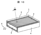
- FIGS. 10 is a perspective view of a conventional corrosive environment monitoring apparatus
- FIG. 11 is a top view of the conventional corrosive environment monitoring apparatus
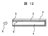
- FIG. 12 is a cross-sectional view taken along line BB of FIG.
- the corrosive environment monitoring apparatus 1 forms a passage structure 4 having one end closed at the center of the box shape and the other end being an opening 5.
- the upper surface of the side surface, upper and lower surfaces, and rear surface constituting the passage structure 4 is formed with the metal thin film 2, and the metal thin film 2 is covered with the transparent substrate 3. Thereby, the corrosion state of the metal thin film 2 is visible from above the corrosion environment monitoring device 1.
- the metal thin film 2 constitutes a sensor portion, and is attached to a part of the wall surface (upper surface in the case of FIG. 10) in the passage structure 4 having the opening 5. Further, the metal thin film 2 can be observed from the ambient atmosphere side (upper side in FIG. 10) so that the film formation surface of the metal thin film 2 is on the passage structure 4 side and the transparent substrate 3 is on the ambient atmosphere side. It is attached.
- a metal having a different color tone from the metal and the corrosion product such as aluminum, iron and zinc can be used.
- the passage structure 4 has a role of controlling the corrosion rate of the metal thin film portion 2 which is a sensor portion due to the corrosive substance 6 present in the environment.
- the passage structure 4 has one opening 5 (the left side of the passage structure in FIGS. 11 and 12), and there is no opening on the right side of the passage structure and is isolated from the surrounding environment.
- the corrosive substances include corrosive gas, flying sea salt, dust, etc., but the corrosive gas will be described below as a representative.
- the corrosive gas 6 present in the environment is removed from the opening 5 of the passage structure 4 because the passage structure 4 does not become a ventilation path when one end is closed (right side in the figure). Gradually invades over time.
- 6 ' represents the corrosive gas 6 that has entered the passage structure 4, and according to FIG. 12 showing the BB cross section of FIG. 11, the corrosive substance 6' that has entered inside is on the opening 5 side. Contact the metal thin film 2.
- the corrosion on the corrosive environment monitoring apparatus 1 is controlled by limiting the diffusion of the corrosive gas 6 'to the direction from the left side of the drawing. Since the concentration flux of the corrosive gas 6 ′ is larger as the distance from the opening 5 is shorter, in the metal thin film 2, the amount of corrosion increases toward the left side closer to the opening 5. This behavior is described, for example, in "Estimation of Silver Corrosion Rate in Sulfur Gas Environment" Material and Environment Vol. 56, p265-271 (2007). In this document, it is required by experiments and analyzes using a metal plate that the corrosion rate decreases as the distance from the source of the corrosive gas 6 'increases. By using this method, the corrosion behavior of the corrosion environment monitoring device can be analyzed.
- the progress of the corrosion stops in a region where the corrosion thickness is the same as the thickness of the metal thin film 2 (a region where the metal thin film 2 corrodes to the interface with the transparent substrate 3).
- the region of the metal thin film 2 is observed from the transparent substrate 3 side, it can be confirmed that the color tone of the metal thin film 2 is changed to the color tone of the corrosion product.
- the corrosion state of the metal thin film 2 after exposure to the corrosion environment monitoring device 1 is shown in the top view of FIG. 13 and the BB cross-sectional view of FIG.
- the corrosion does not proceed any further.
- the corrosive gas 6 present in the environment continues to diffuse from the left side close to the opening 5 and further corrodes the metal film on the right side.
- the region 7 (distance from the left end to the point B in the figure) of the metal thin film 2 that has been corroded in all the film thickness directions is shown as the exposure time elapses. Spread to the right.
- the corrosiveness of the environment is diagnosed based on the thickness of metal corrosion products exposed for one month.
- the thickness of the exposed corrosion product of the metal can be converted from the length of the region 7 of the metal thin film that has been corroded in the film thickness direction by the conventional corrosion environment monitoring device.
- the extension rate of the length of the region 7 of the metal thin film that is corroded in the whole film thickness direction depends on the thickness of the metal thin film and the height of the opening. The elongation rate is faster as the metal thin film is thinner and the opening is higher.
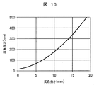
- FIG. 15 shows an example of the relationship between the length of the region 7 of the metal thin film 2 corroded in the film thickness direction by the corrosion environment monitoring apparatus 1 and the thickness of the corrosion product of the exposed metal plate.
- FIG. 15 shows the thickness of the discolored region 7 on the horizontal axis and the thickness of the corrosion product of the exposed metal plate on the vertical axis. Specifically, the thickness of the silver thin film is 20 nm, the passage height is shown. The characteristics when the length is 2 mm, the passage width is 5 mm, and the passage length is 20 mm are shown.
- the slope of the curve is relatively large, and even if the length of the corroded metal thin film region 7 is slightly elongated, the thickness of the corrosion product of the exposed metal plate is greatly increased (measurement accuracy is increased). Low).
- the curve slope is small (even if the length of the corroded metal thin film region 7 is greatly extended, the corrosion product of the exposed metal plate Corrosion environment monitoring equipment (thickness increases slightly) is required.
- the corrosiveness of the environment is diagnosed based on the thickness of the corrosion product of the metal exposed for one month, and in the ISO 11844-1 standard, the thickness of the corrosion product of the metal exposed for one year.
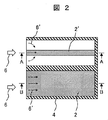
- FIGS. 1 is a perspective view showing the overall configuration of a corrosive environment monitoring apparatus according to Embodiment 1 of the present invention
- FIG. 2 is a top view thereof
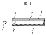
- FIG. 3 is a cross-sectional view taken along line AA in FIG. 2,
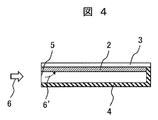
- FIG. It is B sectional drawing.
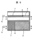
- FIG. 6 and FIG. 7 are top views showing the corrosion state of the metal thin film after the exposure of the corrosion environment monitoring apparatus of Example 1, AA sectional view of the corrosion environment monitoring apparatus of FIG. BB sectional views of the corrosion environment monitoring device are shown respectively.
- Example 1 of FIG. 1 about the metal thin film 2 which is a sensor part, it differs from the 1st metal thin film 2 of the same conditions (covering the whole upper surface of the channel
- the second metal thin film 2 ′ is provided on a part of the upper surface of the metal thin film in the depth direction.
- Other conditions the structure of the gout structure 4, the corrosive gas 6, etc. are the same.
- the corrosive environment monitoring apparatus 1 has a sensor unit composed of metal thin films 2, 2 ′ provided on a transparent substrate 3.
- the metal thin film 2 has the same width as the passage structure 4, and the metal thin film 2 ′ is narrower than the passage structure 4.
- the corrosive gas 6 ′ diffuses in the direction parallel to the passage structure in the passage structure of the metal thin film 2.
- the corrosive gas 6 ′ diffuses in the vertical direction as well as in the direction parallel to the passage structure (diffuses from the side surface of the metal thin film 2) in the passage structure of the metal thin film 2 ′.
- FIG. 5 which shows the corrosion state of the metal thin film after the exposure of the corrosion environment monitoring apparatus of Example 1
- the length of the discoloration region of the metal thin film 2 ′ ( The corrosion result is obtained that the distance from the left end of FIG. 5 to the point A) is longer than the length of the discolored region of the metal thin film 2 (the distance from the left end to the point B in FIG. 5). This will be described in more detail.
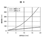
- FIG. 8 is a diagram showing an example of the relationship between the length of the region 7 of the metal thin film 2 corroded in the film thickness direction by the corrosion environment monitoring apparatus 1 and the thickness of the corrosion product of the exposed metal plate in the same manner as FIG. However, the difference in characteristics between the wide sensor (metal thin film 2) and the narrow sensor (metal thin film 2 ') is shown in comparison.
- the narrow metal thin film 2 ′ has a silver thin film width of 1 mm, a silver thin film thickness of 20 nm, a passage height of 2 mm, a passage width of 20 mm, and a passage length of 20 mm.
- the results are shown in which the silver thin film thickness is 20 nm, the passage height is 2 mm, the passage width is 5 mm, and the passage length is 20 mm.
- the narrow metal thin film 2 ′ has a width of 1/5 or less than the wide metal thin film 2 when the metal thin film 2 is narrower than the passage structure 4. This makes it possible to measure both the degree of corrosion of metals exposed for one month in the ASHRAE guidelines and exposed for one year in the ISO 11844-1 standard.
- the corrosion environment monitoring apparatus 1 of the present invention uses the two types of metal thin films 2 and 2 ', the average value can be obtained by obtaining the thickness of the corrosion product by two types of methods. . Furthermore, the ratio of the length of the discolored region of the narrow metal thin film to the length of the discolored region of the wide metal thin film is calculated, and the thickness of the corrosion product can be obtained from this value. Furthermore, in the corrosion environment monitoring apparatus 1 of the present invention, the thickness of the corrosion product is obtained and averaged by three kinds of methods, so that the thickness of the corrosion product can be estimated with high accuracy.
- the thickness of the corrosion product can be obtained from the ratio of the length of the color change region 7 of the narrow metal thin film 2 ′ to the length of the color change region 7 of the wide metal thin film 2 .
- the relationship between the length of the discoloration region of the metal thin film and the corrosion thickness shows linearity as the width of the metal thin film becomes narrower with respect to the width of the passage structure, and conversely with respect to the width of the passage structure. It was found that nonlinearity was exhibited when the widths of the metal thin films were equal. By utilizing this difference in linearity, the thickness of the corrosion product can be obtained from the ratio of the length of the color change region of the narrow metal thin film to the length of the color change region of the wide metal thin film.
- FIG. 9 shows an example of the relationship between the ratio of the length of the discolored region of the narrow metal thin film to the length of the discolored region of the wide metal thin film obtained from FIG. 8 and the corrosion thickness.
- the ratio of the length of the discoloration region and the corrosion thickness have a good linear relationship. This method is suitable for accurately estimating the thickness of the corrosion product.
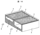
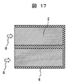
- 16 to 17 show configuration examples of the corrosion environment monitoring apparatus according to Example 2 of the present invention. 16 is a perspective view, and FIG. 17 is a top view.
- a sensor unit composed of two sets of metal thin films 2 provided on a transparent substrate 3 is arranged. Both metal thin films 2 have the same width as the passage structure 4. However, the openings 5 and 5 'of the passage structure 4 are different in height.
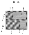
- the corrosion state of the metal thin film after the exposure by the corrosion environment monitoring apparatus 1 is shown in the top view of FIG.
- the corrosive gas 6 in the passage of the opening 5 ' diffuses to the inside of the passage by the wider opening 5'.
- the length of the color changing region of the opening 5 ′ (the distance from the left end of FIG. 18 to the point A) is longer than the length of the color changing region of the opening 5 (FIG. 18).
- a measurement result is obtained that is longer than the distance from the left end to point B).
- FIG. 19 shows an example of the relationship between the length of the discolored region of the metal thin film and the corrosion thickness.
- the silver thin film thickness is 20 nm
- the passage height is 10 mm
- the passage width is 5 mm
- the passage length is 20 mm.
- the silver thin film thickness is 20 nm
- the passage height is 2 mm
- the passage width is 5 mm
- the passage length is 20 mm.
- the average value can be obtained by determining the thickness of the corrosion product by two types of methods. Furthermore, since two types of metal thin films are used, the ratio of the length of the discoloration region of the high opening (narrow opening) to the length of the discoloration region of the low opening (wide opening) is calculated, and this value is calculated. From this, the thickness of the corrosion product can be determined. Furthermore, in the corrosion environment monitoring apparatus 1 of Example 2, the thickness of the corrosion product can be accurately estimated by obtaining and averaging the thickness of the corrosion product by three types of methods.
- the method for obtaining the thickness of the corrosion product from the ratio of the length of the color change region of the low opening to the length of the color change region of the high opening will be explained. It is the same as the method. As shown in FIG. 19, it was found that the relationship between the length of the discoloration region of the metal thin film and the corrosion thickness shows linearity as the opening becomes higher and, on the contrary, non-linearity when the opening becomes lower. By utilizing this difference in linearity, the thickness of the corrosion product can be obtained from the ratio of the length of the color change region of the high opening to the length of the color change region of the low opening.
- FIG. 20 shows an example of the relationship between the ratio of the length of the color change region of the metal thin film in the high opening portion to the length of the color change region of the metal thin film in the low opening portion obtained from FIG. 19 and the corrosion thickness. According to this, in the range where the absolute amount of the corrosion thickness is small, the ratio of the length of the discolored region and the corrosion thickness have a good linear relationship. This method is suitable for accurately estimating the thickness of the corrosion product.
- FIG. 21 shows a configuration example of the corrosion environment monitoring apparatus according to Example 3 of the present invention.
- FIG. 21 shows a system in which the relationship between the wide and narrow metal thin film of Example 1 and the relationship between the height openings of Example 2 are used together.
- An apparatus having a sensing unit provided with a metal thin film is configured.
- the linear relationship between the length ratio of the discolored region and the corrosion thickness can be maintained, and the corrosion of the metal exposed to the ASHRAE guideline for one month in the sensing section with a wide metal thin film attached to the passage of the low opening.
- the thickness of the product can be obtained, and the thickness of the corrosion product of the metal exposed for one year can be obtained according to the ISO 11844-1 standard in the sensing part in which the wide metal thin film is attached to the passage of the low opening.
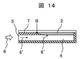
- FIG. 22 shows a configuration example of the corrosive environment monitoring apparatus according to Example 4 of the present invention.
- FIG. 22 shows a system in which the relationship between the wide and narrow metal thin film of Example 1 and the relationship between the high and low openings of Example 2 are used together.
- the corrosive environment monitoring apparatus 1 has a sensor unit composed of the metal thin films 2 and 2 ′ provided on the transparent substrate 3.
- the metal thin film 2 has the same width as the passage structure 4, and the metal thin film 2 ′ is narrower than the passage structure 4.
- the metal thin film 2 ' is attached so as to be in contact with the side wall surface of the opening.
Landscapes
- Life Sciences & Earth Sciences (AREA)
- Biodiversity & Conservation Biology (AREA)
- Ecology (AREA)
- Environmental & Geological Engineering (AREA)
- Environmental Sciences (AREA)
- Physics & Mathematics (AREA)
- Health & Medical Sciences (AREA)
- Chemical & Material Sciences (AREA)
- Analytical Chemistry (AREA)
- Biochemistry (AREA)
- General Health & Medical Sciences (AREA)
- General Physics & Mathematics (AREA)
- Immunology (AREA)
- Pathology (AREA)
- Testing Resistance To Weather, Investigating Materials By Mechanical Methods (AREA)
Abstract
Priority Applications (3)
| Application Number | Priority Date | Filing Date | Title |
|---|---|---|---|
| JP2018510264A JP6609038B2 (ja) | 2016-04-08 | 2017-02-23 | 腐食環境モニタリング装置 |
| CN201780022360.3A CN109073533B (zh) | 2016-04-08 | 2017-02-23 | 腐蚀环境监测装置 |
| EP17778886.6A EP3441745B1 (fr) | 2016-04-08 | 2017-02-23 | Dispositif de surveillance d'environnement corrosif |
Applications Claiming Priority (2)
| Application Number | Priority Date | Filing Date | Title |
|---|---|---|---|
| JP2016077716 | 2016-04-08 | ||
| JP2016-077716 | 2016-04-08 |
Publications (1)
| Publication Number | Publication Date |
|---|---|
| WO2017175507A1 true WO2017175507A1 (fr) | 2017-10-12 |
Family
ID=60001001
Family Applications (1)
| Application Number | Title | Priority Date | Filing Date |
|---|---|---|---|
| PCT/JP2017/006835 WO2017175507A1 (fr) | 2016-04-08 | 2017-02-23 | Dispositif de surveillance d'environnement corrosif |
Country Status (4)
| Country | Link |
|---|---|
| EP (1) | EP3441745B1 (fr) |
| JP (1) | JP6609038B2 (fr) |
| CN (1) | CN109073533B (fr) |
| WO (1) | WO2017175507A1 (fr) |
Cited By (2)
| Publication number | Priority date | Publication date | Assignee | Title |
|---|---|---|---|---|
| US10330586B2 (en) * | 2016-07-20 | 2019-06-25 | Honeywell International Inc. | Corrosion monitor |
| WO2020039611A1 (fr) * | 2018-08-23 | 2020-02-27 | 株式会社日立製作所 | Procédé et système de surveillance d'un environnement corrosif |
Families Citing this family (1)
| Publication number | Priority date | Publication date | Assignee | Title |
|---|---|---|---|---|
| CN114236105B (zh) * | 2021-11-30 | 2023-11-28 | 浙江省二建建设集团有限公司 | 一种垃圾池壁混凝土腐蚀的监测装置及方法 |
Citations (5)
| Publication number | Priority date | Publication date | Assignee | Title |
|---|---|---|---|---|
| JP2008281499A (ja) * | 2007-05-14 | 2008-11-20 | Ntn Corp | 腐食環境センサおよびセンサシステム |
| JP2008304212A (ja) * | 2007-06-05 | 2008-12-18 | Mitsubishi Heavy Ind Ltd | 試験体及び試験体の製造方法 |
| WO2013042179A1 (fr) * | 2011-09-20 | 2013-03-28 | 株式会社日立製作所 | Dispositif et procédé de surveillance d'un environnement corrosif |
| JP2013190241A (ja) * | 2012-03-13 | 2013-09-26 | Hitachi Ltd | 腐食環境モニタリング装置 |
| US20130265064A1 (en) * | 2012-04-04 | 2013-10-10 | International Business Machines Corporation | Corrosion detector apparatus for universal assessment of pollution in data centers |
Family Cites Families (5)
| Publication number | Priority date | Publication date | Assignee | Title |
|---|---|---|---|---|
| US8390306B2 (en) * | 2010-08-11 | 2013-03-05 | International Business Machines Corporation | Corrosion sensors |
| CN102645457A (zh) * | 2012-05-04 | 2012-08-22 | 山东电力研究院 | 大气环境污染物腐蚀监测传感器 |
| CN202533402U (zh) * | 2012-05-04 | 2012-11-14 | 山东电力研究院 | 大气环境污染物腐蚀监测传感器 |
| JP6362920B2 (ja) * | 2014-05-16 | 2018-07-25 | 株式会社日立製作所 | 腐食環境モニタリング装置及び方法 |
| CN106226226B (zh) * | 2016-07-11 | 2019-04-02 | 国网山东省电力公司电力科学研究院 | 一种大气环境腐蚀性检测传感器及评价方法 |
-
2017
- 2017-02-23 JP JP2018510264A patent/JP6609038B2/ja active Active
- 2017-02-23 EP EP17778886.6A patent/EP3441745B1/fr active Active
- 2017-02-23 WO PCT/JP2017/006835 patent/WO2017175507A1/fr active Application Filing
- 2017-02-23 CN CN201780022360.3A patent/CN109073533B/zh active Active
Patent Citations (5)
| Publication number | Priority date | Publication date | Assignee | Title |
|---|---|---|---|---|
| JP2008281499A (ja) * | 2007-05-14 | 2008-11-20 | Ntn Corp | 腐食環境センサおよびセンサシステム |
| JP2008304212A (ja) * | 2007-06-05 | 2008-12-18 | Mitsubishi Heavy Ind Ltd | 試験体及び試験体の製造方法 |
| WO2013042179A1 (fr) * | 2011-09-20 | 2013-03-28 | 株式会社日立製作所 | Dispositif et procédé de surveillance d'un environnement corrosif |
| JP2013190241A (ja) * | 2012-03-13 | 2013-09-26 | Hitachi Ltd | 腐食環境モニタリング装置 |
| US20130265064A1 (en) * | 2012-04-04 | 2013-10-10 | International Business Machines Corporation | Corrosion detector apparatus for universal assessment of pollution in data centers |
Cited By (7)
| Publication number | Priority date | Publication date | Assignee | Title |
|---|---|---|---|---|
| US10330586B2 (en) * | 2016-07-20 | 2019-06-25 | Honeywell International Inc. | Corrosion monitor |
| WO2020039611A1 (fr) * | 2018-08-23 | 2020-02-27 | 株式会社日立製作所 | Procédé et système de surveillance d'un environnement corrosif |
| JP2020030128A (ja) * | 2018-08-23 | 2020-02-27 | 株式会社日立製作所 | 腐食環境モニタリング方法および腐食環境モニタリングシステム |
| CN112543865A (zh) * | 2018-08-23 | 2021-03-23 | 株式会社日立制作所 | 腐蚀环境监测方法及腐蚀环境监测系统 |
| JP7033034B2 (ja) | 2018-08-23 | 2022-03-09 | 株式会社日立製作所 | 腐食環境モニタリング方法および腐食環境モニタリングシステム |
| US11460394B2 (en) | 2018-08-23 | 2022-10-04 | Hitachi, Ltd. | Corrosive environment monitoring method and corrosive environment monitoring system |
| CN112543865B (zh) * | 2018-08-23 | 2023-11-07 | 株式会社日立制作所 | 腐蚀环境监测方法及腐蚀环境监测系统 |
Also Published As
| Publication number | Publication date |
|---|---|
| EP3441745A1 (fr) | 2019-02-13 |
| CN109073533B (zh) | 2021-03-05 |
| EP3441745B1 (fr) | 2021-04-07 |
| EP3441745A4 (fr) | 2020-01-01 |
| CN109073533A (zh) | 2018-12-21 |
| JPWO2017175507A1 (ja) | 2019-01-31 |
| JP6609038B2 (ja) | 2019-11-20 |
Similar Documents
| Publication | Publication Date | Title |
|---|---|---|
| WO2017061182A1 (fr) | Dispositif et procédé de surveillance d'environnement corrosif | |
| US9568455B2 (en) | Corrosive environment monitoring apparatus and method | |
| JP6362920B2 (ja) | 腐食環境モニタリング装置及び方法 | |
| JP3895087B2 (ja) | 劣化診断方法 | |
| JP6609038B2 (ja) | 腐食環境モニタリング装置 | |
| JP5798955B2 (ja) | 腐食環境モニタリング装置 | |
| US20090216464A1 (en) | Integrated in-line oil monitoring apparatus | |
| JP7033034B2 (ja) | 腐食環境モニタリング方法および腐食環境モニタリングシステム | |
| JP7226417B2 (ja) | 硫化水素濃度推定装置 | |
| US10151683B2 (en) | Corrosion sensor using electrical continuity | |
| JP3602782B2 (ja) | 劣化度測定キットおよびこの劣化度測定キットによる電子回路基板の劣化寿命診断法 | |
| JPH1090165A (ja) | 腐食環境モニタリング装置 | |
| WO2022091590A1 (fr) | Système de surveillance d'environnement corrosif et procédé de surveillance d'environnement corrosif | |
| JP2005257532A (ja) | 環境診断ツールおよびそれを用いた環境測定方法 | |
| JP2006010497A (ja) | 環境診断ツール | |
| JP2002350329A (ja) | 腐食センサ | |
| JP2006162570A (ja) | 油の酸性、塩基性度検出用基準電極 | |
| JP2012047590A (ja) | 鋼構造物の腐食状況把握方法 |
Legal Events
| Date | Code | Title | Description |
|---|---|---|---|
| WWE | Wipo information: entry into national phase |
Ref document number: 2018510264 Country of ref document: JP |
|
| NENP | Non-entry into the national phase |
Ref country code: DE |
|
| WWE | Wipo information: entry into national phase |
Ref document number: 2017778886 Country of ref document: EP |
|
| ENP | Entry into the national phase |
Ref document number: 2017778886 Country of ref document: EP Effective date: 20181108 |
|
| 121 | Ep: the epo has been informed by wipo that ep was designated in this application |
Ref document number: 17778886 Country of ref document: EP Kind code of ref document: A1 |