WO2017175507A1 - Corrosive environment monitoring device - Google Patents

Corrosive environment monitoring device Download PDF

Info

Publication number
WO2017175507A1
WO2017175507A1 PCT/JP2017/006835 JP2017006835W WO2017175507A1 WO 2017175507 A1 WO2017175507 A1 WO 2017175507A1 JP 2017006835 W JP2017006835 W JP 2017006835W WO 2017175507 A1 WO2017175507 A1 WO 2017175507A1
Authority
WO
WIPO (PCT)
Prior art keywords
environment monitoring
thin film
corrosion
metal thin
monitoring device
Prior art date
Application number
PCT/JP2017/006835
Other languages
French (fr)
Japanese (ja)
Inventor
南谷 林太郎
Original Assignee
株式会社日立製作所
Priority date (The priority date is an assumption and is not a legal conclusion. Google has not performed a legal analysis and makes no representation as to the accuracy of the date listed.)
Filing date
Publication date
Application filed by 株式会社日立製作所 filed Critical 株式会社日立製作所
Priority to JP2018510264A priority Critical patent/JP6609038B2/en
Priority to CN201780022360.3A priority patent/CN109073533B/en
Priority to EP17778886.6A priority patent/EP3441745B1/en
Publication of WO2017175507A1 publication Critical patent/WO2017175507A1/en

Links

Images

Classifications

    • GPHYSICS
    • G01MEASURING; TESTING
    • G01NINVESTIGATING OR ANALYSING MATERIALS BY DETERMINING THEIR CHEMICAL OR PHYSICAL PROPERTIES
    • G01N17/00Investigating resistance of materials to the weather, to corrosion, or to light
    • G01N17/04Corrosion probes

Definitions

  • the present invention relates to a corrosive environment monitoring device for measuring the degree of corrosion by corrosive gas existing in an indoor environment, mainly an environment where an electric and electronic device is installed.
  • a method for evaluating the corrosiveness of the installation environment of electric and electronic devices a method for evaluating the degree of corrosion of copper, silver, aluminum, iron, and zinc exposed for a certain period of time is normally used in the ISO 11844-1 standard. It is known that copper, silver, aluminum, iron, and zinc corrode with any corrosive gas of SO 2 , NO 2 , and H 2 S, although the degree of influence is different.
  • the ISO standard quantifies the degree of corrosion of a metal exposed for one year by gravimetry or the corrosion product of an exposed metal by electrochemical measurements.
  • the guidelines for evaluating the corrosiveness of the installation environment from the ASHRAE (American Society of Heating, Refrigerating and Air-Conditioning) (ASHRAE TC9.9, 2011 Gasoseous and Customs Guidelines Guidelines for Data Centers) has been reported.
  • the ASHRAE guidelines quantify the degree of corrosion of metals exposed for one month by electrochemical measurements.
  • Patent Documents 1 and 2 describe that “as a method for measuring the type and concentration of a corrosive gas present in an environmental atmosphere, copper, silver, aluminum, iron, and 52 alloy are used.
  • a calibration curve of an X-ray microanalyzer showing the correlation between the concentration of the corrosive gas and the X-ray intensity of the corrosion product generated by leaving for a predetermined period for five kinds of metal pieces is obtained in advance, The five kinds of metal pieces are allowed to stand for a predetermined period of time, and the type of the corrosive gas is estimated from the corrosive state, and then the X-ray intensity of the corrosive gas component is obtained from the corrosion product using an X-ray microanalyzer.
  • the atmosphere investigation method is characterized in that the gas concentration is obtained by comparison with the calibration curve.
  • Patent Document 3 discloses that the corrosiveness of the environment is quantified by the corrosion thickness of a metal, “a thin film made of two or more different materials made of a metal, an alloy thereof, or a compound thereof is formed as a single insulator. Sequentially formed on a substrate, each thin film has different physical and / or chemical properties, and gas components in multiple environments are detected using the difference in physical or / and chemical properties of the thin film An environmental evaluation method and an environmental evaluation apparatus using the same, wherein the environmental evaluation is performed by detecting a change in physical or / and chemical properties of the material of the element. It is described to do.
  • Patent Document 4 discloses that the corrosiveness of the environment is quantified by the corrosion thickness of the metal, “a passage structure having one opening and a passage parallel to the diffusion direction of the corrosive substance from the opening.
  • the first and second corrosive environments are provided with first and second corrosive environment monitoring devices, wherein a part of the wall surface of the structure is formed of a transparent substrate, and the metal thin film is formed on the transparent substrate.
  • the monitoring device can measure the shape and size of the color tone region changed by the corrosion product of the metal thin film left in the measurement environment for a predetermined period through the transparent substrate, and the metal of the first corrosion environment monitoring device.
  • the thin film is made of a predetermined material
  • the metal thin film of the second corrosion environment monitoring device is made of a material different from the material of the metal thin film of the first corrosion environment monitoring device. It is described that a corrosive environment monitoring device ", wherein Rukoto.
  • an electric circuit is driven to detect changes in the light reflectance, light transmittance, and electric resistance element of the thin film element and convert them into an electric signal.
  • a power supply is required.
  • a passage structure having one opening and a part of the wall surface of the passage structure parallel to the diffusion direction of the corrosive substance from the opening are formed of a transparent substrate
  • the discoloration area of the metal thin film is slight and the length is short after one month of exposure specified in the ASHRAE guidelines.
  • the corrosion thickness of silver is 20 nm or less and the corrosion thickness of copper is 30 nm or less).
  • any corrosion environment monitoring device has only one sensing unit, and it is difficult to correct highly varied corrosion data. There are challenges.
  • An object of the present invention is to provide a corrosion environment monitoring device capable of measuring the degree of corrosion of metals over a wide range.
  • the metal thin film 2 is formed on the upper and lower surfaces or a part of the side surface of the opening of the passage structure in which one end of the box shape is closed and the other end is an opening.
  • a corrosion environment monitoring device comprising a sensor portion formed by covering a metal thin film with a transparent substrate, the corrosion environment monitoring device comprising a plurality of corrosion environment monitoring portions arranged adjacent to each other.
  • the corrosion environment monitoring device is characterized in that the corrosion detection conditions of the metal thin film in the plurality of corrosion environment monitoring units are different.
  • a metal power source such as a commercial power source or a storage battery is not required in a narrow place in an electronic device casing to be diagnosed on the spot without the need for a special analytical instrument.
  • the degree of corrosion can be measured.
  • corrosivity in a relatively clean environment can be diagnosed according to the ASHRAE guidelines after a short period of exposure for one month, and further, it has been relatively contaminated by a long period of exposure for one year. Corrosion in the environment can be diagnosed according to the ISO11844-1 standard.
  • FIG. 1 is a perspective view of a corrosive environment monitoring apparatus according to Embodiment 1.
  • FIG. 3 is a cross-sectional view of the corrosive environment monitoring apparatus of FIG.
  • FIG. 3 is a BB cross-sectional view of the corrosion environment monitoring apparatus of FIG.
  • the top view which shows the corrosion condition of the metal thin film after the exposure of the corrosion environment monitoring apparatus of Example 1.
  • FIG. FIG. 6 is a cross-sectional view taken along the line AA of the corrosive environment monitoring apparatus of FIG. 5.
  • FIG. 6 is a BB cross-sectional view of the corrosion environment monitoring apparatus of FIG.
  • FIG. 12 is a cross-sectional view taken along line BB in FIG.
  • FIG. 11 showing the corrosion state of the metal thin film after exposure by the conventional corrosion environment monitoring device.
  • FIG. 6 is a perspective view of a corrosive environment monitoring apparatus according to a second embodiment. The top view of the corrosion environment monitoring apparatus of Example 2.
  • FIG. 6 is a perspective view of a corrosive environment monitoring device according to a third embodiment.
  • FIG. 6 is a perspective view of a corrosive environment monitoring apparatus according to a fourth embodiment.
  • FIGS. 10 is a perspective view of a conventional corrosive environment monitoring apparatus
  • FIG. 11 is a top view of the conventional corrosive environment monitoring apparatus
  • FIG. 12 is a cross-sectional view taken along line BB of FIG.
  • the corrosive environment monitoring apparatus 1 forms a passage structure 4 having one end closed at the center of the box shape and the other end being an opening 5.
  • the upper surface of the side surface, upper and lower surfaces, and rear surface constituting the passage structure 4 is formed with the metal thin film 2, and the metal thin film 2 is covered with the transparent substrate 3. Thereby, the corrosion state of the metal thin film 2 is visible from above the corrosion environment monitoring device 1.
  • the metal thin film 2 constitutes a sensor portion, and is attached to a part of the wall surface (upper surface in the case of FIG. 10) in the passage structure 4 having the opening 5. Further, the metal thin film 2 can be observed from the ambient atmosphere side (upper side in FIG. 10) so that the film formation surface of the metal thin film 2 is on the passage structure 4 side and the transparent substrate 3 is on the ambient atmosphere side. It is attached.
  • a metal having a different color tone from the metal and the corrosion product such as aluminum, iron and zinc can be used.
  • the passage structure 4 has a role of controlling the corrosion rate of the metal thin film portion 2 which is a sensor portion due to the corrosive substance 6 present in the environment.
  • the passage structure 4 has one opening 5 (the left side of the passage structure in FIGS. 11 and 12), and there is no opening on the right side of the passage structure and is isolated from the surrounding environment.
  • the corrosive substances include corrosive gas, flying sea salt, dust, etc., but the corrosive gas will be described below as a representative.
  • the corrosive gas 6 present in the environment is removed from the opening 5 of the passage structure 4 because the passage structure 4 does not become a ventilation path when one end is closed (right side in the figure). Gradually invades over time.
  • 6 ' represents the corrosive gas 6 that has entered the passage structure 4, and according to FIG. 12 showing the BB cross section of FIG. 11, the corrosive substance 6' that has entered inside is on the opening 5 side. Contact the metal thin film 2.
  • the corrosion on the corrosive environment monitoring apparatus 1 is controlled by limiting the diffusion of the corrosive gas 6 'to the direction from the left side of the drawing. Since the concentration flux of the corrosive gas 6 ′ is larger as the distance from the opening 5 is shorter, in the metal thin film 2, the amount of corrosion increases toward the left side closer to the opening 5. This behavior is described, for example, in "Estimation of Silver Corrosion Rate in Sulfur Gas Environment" Material and Environment Vol. 56, p265-271 (2007). In this document, it is required by experiments and analyzes using a metal plate that the corrosion rate decreases as the distance from the source of the corrosive gas 6 'increases. By using this method, the corrosion behavior of the corrosion environment monitoring device can be analyzed.
  • the progress of the corrosion stops in a region where the corrosion thickness is the same as the thickness of the metal thin film 2 (a region where the metal thin film 2 corrodes to the interface with the transparent substrate 3).
  • the region of the metal thin film 2 is observed from the transparent substrate 3 side, it can be confirmed that the color tone of the metal thin film 2 is changed to the color tone of the corrosion product.
  • the corrosion state of the metal thin film 2 after exposure to the corrosion environment monitoring device 1 is shown in the top view of FIG. 13 and the BB cross-sectional view of FIG.
  • the corrosion does not proceed any further.
  • the corrosive gas 6 present in the environment continues to diffuse from the left side close to the opening 5 and further corrodes the metal film on the right side.
  • the region 7 (distance from the left end to the point B in the figure) of the metal thin film 2 that has been corroded in all the film thickness directions is shown as the exposure time elapses. Spread to the right.
  • the corrosiveness of the environment is diagnosed based on the thickness of metal corrosion products exposed for one month.
  • the thickness of the exposed corrosion product of the metal can be converted from the length of the region 7 of the metal thin film that has been corroded in the film thickness direction by the conventional corrosion environment monitoring device.
  • the extension rate of the length of the region 7 of the metal thin film that is corroded in the whole film thickness direction depends on the thickness of the metal thin film and the height of the opening. The elongation rate is faster as the metal thin film is thinner and the opening is higher.
  • FIG. 15 shows an example of the relationship between the length of the region 7 of the metal thin film 2 corroded in the film thickness direction by the corrosion environment monitoring apparatus 1 and the thickness of the corrosion product of the exposed metal plate.
  • FIG. 15 shows the thickness of the discolored region 7 on the horizontal axis and the thickness of the corrosion product of the exposed metal plate on the vertical axis. Specifically, the thickness of the silver thin film is 20 nm, the passage height is shown. The characteristics when the length is 2 mm, the passage width is 5 mm, and the passage length is 20 mm are shown.
  • the slope of the curve is relatively large, and even if the length of the corroded metal thin film region 7 is slightly elongated, the thickness of the corrosion product of the exposed metal plate is greatly increased (measurement accuracy is increased). Low).
  • the curve slope is small (even if the length of the corroded metal thin film region 7 is greatly extended, the corrosion product of the exposed metal plate Corrosion environment monitoring equipment (thickness increases slightly) is required.
  • the corrosiveness of the environment is diagnosed based on the thickness of the corrosion product of the metal exposed for one month, and in the ISO 11844-1 standard, the thickness of the corrosion product of the metal exposed for one year.
  • FIGS. 1 is a perspective view showing the overall configuration of a corrosive environment monitoring apparatus according to Embodiment 1 of the present invention
  • FIG. 2 is a top view thereof
  • FIG. 3 is a cross-sectional view taken along line AA in FIG. 2,
  • FIG. It is B sectional drawing.
  • FIG. 6 and FIG. 7 are top views showing the corrosion state of the metal thin film after the exposure of the corrosion environment monitoring apparatus of Example 1, AA sectional view of the corrosion environment monitoring apparatus of FIG. BB sectional views of the corrosion environment monitoring device are shown respectively.
  • Example 1 of FIG. 1 about the metal thin film 2 which is a sensor part, it differs from the 1st metal thin film 2 of the same conditions (covering the whole upper surface of the channel
  • the second metal thin film 2 ′ is provided on a part of the upper surface of the metal thin film in the depth direction.
  • Other conditions the structure of the gout structure 4, the corrosive gas 6, etc. are the same.
  • the corrosive environment monitoring apparatus 1 has a sensor unit composed of metal thin films 2, 2 ′ provided on a transparent substrate 3.
  • the metal thin film 2 has the same width as the passage structure 4, and the metal thin film 2 ′ is narrower than the passage structure 4.
  • the corrosive gas 6 ′ diffuses in the direction parallel to the passage structure in the passage structure of the metal thin film 2.
  • the corrosive gas 6 ′ diffuses in the vertical direction as well as in the direction parallel to the passage structure (diffuses from the side surface of the metal thin film 2) in the passage structure of the metal thin film 2 ′.
  • FIG. 5 which shows the corrosion state of the metal thin film after the exposure of the corrosion environment monitoring apparatus of Example 1
  • the length of the discoloration region of the metal thin film 2 ′ ( The corrosion result is obtained that the distance from the left end of FIG. 5 to the point A) is longer than the length of the discolored region of the metal thin film 2 (the distance from the left end to the point B in FIG. 5). This will be described in more detail.
  • FIG. 8 is a diagram showing an example of the relationship between the length of the region 7 of the metal thin film 2 corroded in the film thickness direction by the corrosion environment monitoring apparatus 1 and the thickness of the corrosion product of the exposed metal plate in the same manner as FIG. However, the difference in characteristics between the wide sensor (metal thin film 2) and the narrow sensor (metal thin film 2 ') is shown in comparison.
  • the narrow metal thin film 2 ′ has a silver thin film width of 1 mm, a silver thin film thickness of 20 nm, a passage height of 2 mm, a passage width of 20 mm, and a passage length of 20 mm.
  • the results are shown in which the silver thin film thickness is 20 nm, the passage height is 2 mm, the passage width is 5 mm, and the passage length is 20 mm.
  • the narrow metal thin film 2 ′ has a width of 1/5 or less than the wide metal thin film 2 when the metal thin film 2 is narrower than the passage structure 4. This makes it possible to measure both the degree of corrosion of metals exposed for one month in the ASHRAE guidelines and exposed for one year in the ISO 11844-1 standard.
  • the corrosion environment monitoring apparatus 1 of the present invention uses the two types of metal thin films 2 and 2 ', the average value can be obtained by obtaining the thickness of the corrosion product by two types of methods. . Furthermore, the ratio of the length of the discolored region of the narrow metal thin film to the length of the discolored region of the wide metal thin film is calculated, and the thickness of the corrosion product can be obtained from this value. Furthermore, in the corrosion environment monitoring apparatus 1 of the present invention, the thickness of the corrosion product is obtained and averaged by three kinds of methods, so that the thickness of the corrosion product can be estimated with high accuracy.
  • the thickness of the corrosion product can be obtained from the ratio of the length of the color change region 7 of the narrow metal thin film 2 ′ to the length of the color change region 7 of the wide metal thin film 2 .
  • the relationship between the length of the discoloration region of the metal thin film and the corrosion thickness shows linearity as the width of the metal thin film becomes narrower with respect to the width of the passage structure, and conversely with respect to the width of the passage structure. It was found that nonlinearity was exhibited when the widths of the metal thin films were equal. By utilizing this difference in linearity, the thickness of the corrosion product can be obtained from the ratio of the length of the color change region of the narrow metal thin film to the length of the color change region of the wide metal thin film.
  • FIG. 9 shows an example of the relationship between the ratio of the length of the discolored region of the narrow metal thin film to the length of the discolored region of the wide metal thin film obtained from FIG. 8 and the corrosion thickness.
  • the ratio of the length of the discoloration region and the corrosion thickness have a good linear relationship. This method is suitable for accurately estimating the thickness of the corrosion product.
  • 16 to 17 show configuration examples of the corrosion environment monitoring apparatus according to Example 2 of the present invention. 16 is a perspective view, and FIG. 17 is a top view.
  • a sensor unit composed of two sets of metal thin films 2 provided on a transparent substrate 3 is arranged. Both metal thin films 2 have the same width as the passage structure 4. However, the openings 5 and 5 'of the passage structure 4 are different in height.
  • the corrosion state of the metal thin film after the exposure by the corrosion environment monitoring apparatus 1 is shown in the top view of FIG.
  • the corrosive gas 6 in the passage of the opening 5 ' diffuses to the inside of the passage by the wider opening 5'.
  • the length of the color changing region of the opening 5 ′ (the distance from the left end of FIG. 18 to the point A) is longer than the length of the color changing region of the opening 5 (FIG. 18).
  • a measurement result is obtained that is longer than the distance from the left end to point B).
  • FIG. 19 shows an example of the relationship between the length of the discolored region of the metal thin film and the corrosion thickness.
  • the silver thin film thickness is 20 nm
  • the passage height is 10 mm
  • the passage width is 5 mm
  • the passage length is 20 mm.
  • the silver thin film thickness is 20 nm
  • the passage height is 2 mm
  • the passage width is 5 mm
  • the passage length is 20 mm.
  • the average value can be obtained by determining the thickness of the corrosion product by two types of methods. Furthermore, since two types of metal thin films are used, the ratio of the length of the discoloration region of the high opening (narrow opening) to the length of the discoloration region of the low opening (wide opening) is calculated, and this value is calculated. From this, the thickness of the corrosion product can be determined. Furthermore, in the corrosion environment monitoring apparatus 1 of Example 2, the thickness of the corrosion product can be accurately estimated by obtaining and averaging the thickness of the corrosion product by three types of methods.
  • the method for obtaining the thickness of the corrosion product from the ratio of the length of the color change region of the low opening to the length of the color change region of the high opening will be explained. It is the same as the method. As shown in FIG. 19, it was found that the relationship between the length of the discoloration region of the metal thin film and the corrosion thickness shows linearity as the opening becomes higher and, on the contrary, non-linearity when the opening becomes lower. By utilizing this difference in linearity, the thickness of the corrosion product can be obtained from the ratio of the length of the color change region of the high opening to the length of the color change region of the low opening.
  • FIG. 20 shows an example of the relationship between the ratio of the length of the color change region of the metal thin film in the high opening portion to the length of the color change region of the metal thin film in the low opening portion obtained from FIG. 19 and the corrosion thickness. According to this, in the range where the absolute amount of the corrosion thickness is small, the ratio of the length of the discolored region and the corrosion thickness have a good linear relationship. This method is suitable for accurately estimating the thickness of the corrosion product.
  • FIG. 21 shows a configuration example of the corrosion environment monitoring apparatus according to Example 3 of the present invention.
  • FIG. 21 shows a system in which the relationship between the wide and narrow metal thin film of Example 1 and the relationship between the height openings of Example 2 are used together.
  • An apparatus having a sensing unit provided with a metal thin film is configured.
  • the linear relationship between the length ratio of the discolored region and the corrosion thickness can be maintained, and the corrosion of the metal exposed to the ASHRAE guideline for one month in the sensing section with a wide metal thin film attached to the passage of the low opening.
  • the thickness of the product can be obtained, and the thickness of the corrosion product of the metal exposed for one year can be obtained according to the ISO 11844-1 standard in the sensing part in which the wide metal thin film is attached to the passage of the low opening.
  • FIG. 22 shows a configuration example of the corrosive environment monitoring apparatus according to Example 4 of the present invention.
  • FIG. 22 shows a system in which the relationship between the wide and narrow metal thin film of Example 1 and the relationship between the high and low openings of Example 2 are used together.
  • the corrosive environment monitoring apparatus 1 has a sensor unit composed of the metal thin films 2 and 2 ′ provided on the transparent substrate 3.
  • the metal thin film 2 has the same width as the passage structure 4, and the metal thin film 2 ′ is narrower than the passage structure 4.
  • the metal thin film 2 ' is attached so as to be in contact with the side wall surface of the opening.

Abstract

The purpose of the present invention is to provide a corrosive environment monitoring device that can measure the degree of corrosion of a metal, on site without requiring a special analysis apparatus, in a narrow location in an electronic apparatus chassis to be diagnosed, over a period ranging from a short period to a long period, without requiring a power source such as a commercial power source, a storage battery, or the like. Provided is a corrosive environment monitoring device provided with a sensor unit formed by disposing a metal thin film 2 on part of a top or bottom surface or a side surface that faces an open section of a box-shaped passage structure with one end closed and the other end open, and covering the metal thin film with a transparent substrate. The corrosive environment monitoring device is characterized by being provided with a plurality of corrosive environment monitoring units disposed so that the open sections are adjacent, and in that the corrosion sensing conditions of the metal thin films of the plurality of corrosive environment monitoring units are configured to differ.

Description

腐食環境モニタリング装置Corrosion environment monitoring device
 本発明は、屋内環境、主に電気電子装置が設置されている環境を対象に、当該環境中に存在する腐食性ガスによる腐食度合いを測定する腐食環境モニタリング装置に関する。 The present invention relates to a corrosive environment monitoring device for measuring the degree of corrosion by corrosive gas existing in an indoor environment, mainly an environment where an electric and electronic device is installed.
 電気電子装置では、対象装置を安定に稼動させる目的のために、長期にわたる信頼性が要求されている。また高速化や省スペース化のために、高密度実装構造が採用され微細配線構造や薄膜めっき構造からなる電気電子部品が数多く搭載されている。これらの電気電子部品ではわずかな腐食損傷が電気特性または磁気特性を変動させて故障や誤動作の原因となるため、その腐食損傷を抑制することが電気電子装置の信頼性上の課題に挙げられている。環境の腐食性の程度に応じた防食対策を設計および保守に反映させるため、電気電子装置の設置環境の腐食性を、簡単に短期間で精度良く評価し続けることが求められている。また電気電子装置では、省スペース化のため環境の腐食性を診断する装置も小型軽量であることが求められている。 In electrical and electronic equipment, long-term reliability is required for the purpose of stably operating the target equipment. In order to increase speed and save space, a high-density mounting structure is adopted, and a large number of electrical and electronic parts having a fine wiring structure or a thin-film plating structure are mounted. In these electrical and electronic parts, slight corrosion damage causes fluctuations in electrical or magnetic characteristics, leading to failures and malfunctions. Therefore, suppressing corrosion damage is listed as a reliability issue for electrical and electronic equipment. Yes. In order to reflect anticorrosion measures according to the degree of corrosiveness of the environment in design and maintenance, it is required to continue to evaluate the corrosiveness of the installation environment of electric and electronic devices easily and accurately in a short period of time. In addition, in an electric / electronic device, a device for diagnosing environmental corrosivity is also required to be small and light in order to save space.
 これに対し電気電子装置の設置環境の腐食性を評価する方法として、ISO11844-1規格では一定期間暴露した銅、銀、アルミニウム、鉄、亜鉛の腐食度合いを評価する方法が通常用いられている。銅、銀、アルミニウム、鉄、亜鉛は、影響程度は異なるがSO,NO,HSのいずれの腐食性ガスで腐食することが知られている。ISO規格では、1年間暴露した金属の腐食度合いを重量法で、または暴露した金属の腐食生成物を電気化学測定で定量化する。 On the other hand, as a method for evaluating the corrosiveness of the installation environment of electric and electronic devices, a method for evaluating the degree of corrosion of copper, silver, aluminum, iron, and zinc exposed for a certain period of time is normally used in the ISO 11844-1 standard. It is known that copper, silver, aluminum, iron, and zinc corrode with any corrosive gas of SO 2 , NO 2 , and H 2 S, although the degree of influence is different. The ISO standard quantifies the degree of corrosion of a metal exposed for one year by gravimetry or the corrosion product of an exposed metal by electrochemical measurements.
 また設置環境の腐食性を評価する他の方法として、ASHRAE(アメリカ暖房冷凍空調学会)からデータセンタ設置環境の腐食性を評価するガイドライン(ASHRAE TC9.9、2011 Gaseous and Particulate Contamination Guidelines For Data Centers)が報告されている。ASHRAEガイドラインでは、1カ月間暴露した金属の腐食度合いを電気化学測定で定量化する。 As another method for evaluating the corrosiveness of the installation environment, the guidelines for evaluating the corrosivity of the data center installation environment from the ASHRAE (American Society of Heating, Refrigerating and Air-Conditioning) (ASHRAE TC9.9, 2011 Gasoseous and Customs Guidelines Guidelines for Data Centers) Has been reported. The ASHRAE guidelines quantify the degree of corrosion of metals exposed for one month by electrochemical measurements.
 さらに本技術分野の背景技術として、特許文献1、2には、「環境雰囲気中に存在する腐蝕性ガスの種類と濃度とを測定する方法として、銅、銀、アルミニウム、鉄および52アロイからなる5種類の金属片について腐蝕性ガスの濃度と所定期間の放置により生じた腐蝕生成物のX線強度との相関関係を示すX線マイクロアナライザの検量線を予め求めておき、被調査環境雰囲気中に前記5種類の金属片を所定期間に亙って放置し、腐蝕状態から腐蝕性ガスの種類を推定した後、該腐蝕生成物をX線マイクロアナライザにより腐蝕性ガス成分のX線強度を求め、前記検量線と比較してガスの濃度を求めることを特徴とする雰囲気調査方法」とすることが記載されている。 Further, as background art of this technical field, Patent Documents 1 and 2 describe that “as a method for measuring the type and concentration of a corrosive gas present in an environmental atmosphere, copper, silver, aluminum, iron, and 52 alloy are used. A calibration curve of an X-ray microanalyzer showing the correlation between the concentration of the corrosive gas and the X-ray intensity of the corrosion product generated by leaving for a predetermined period for five kinds of metal pieces is obtained in advance, The five kinds of metal pieces are allowed to stand for a predetermined period of time, and the type of the corrosive gas is estimated from the corrosive state, and then the X-ray intensity of the corrosive gas component is obtained from the corrosion product using an X-ray microanalyzer. The atmosphere investigation method is characterized in that the gas concentration is obtained by comparison with the calibration curve.
 また、環境の腐食性を金属の腐食厚さにより定量化するものとして特許文献3には、「金属あるいはその合金、あるいはその化合物からなる2種類以上の異なる材料からなる薄膜を一枚の絶縁物基板上に順次形成し、各々の薄膜が異なる物理的あるいは/および化学的性質を有し、該薄膜の有する物理的あるいは/および化学的性質の違いを用いて複数の環境中のガス成分を検知する検出素子を構成し、該素子の材料の物理的あるいは/および化学的特性の変化を検出することにより環境評価を行ったことを特徴とする環境評価方式およびそれを用いた環境評価装置」とすることが記載されている。 Patent Document 3 discloses that the corrosiveness of the environment is quantified by the corrosion thickness of a metal, “a thin film made of two or more different materials made of a metal, an alloy thereof, or a compound thereof is formed as a single insulator. Sequentially formed on a substrate, each thin film has different physical and / or chemical properties, and gas components in multiple environments are detected using the difference in physical or / and chemical properties of the thin film An environmental evaluation method and an environmental evaluation apparatus using the same, wherein the environmental evaluation is performed by detecting a change in physical or / and chemical properties of the material of the element. It is described to do.
 また、環境の腐食性を金属の腐食厚さにより定量化するものとして特許文献4には、「一つの開口部を有する通路構造と、前記開口部からの腐食性物質の拡散方向と平行な通路構造の一部の壁面が透明基板で形成され、前記透明基板の上に形成した金属薄膜とで構成される第一及び第二の腐食環境モニタリング装置を備え、前記第一及び第二の腐食環境モニタリング装置は、所定期間に渡り被測定環境中に放置した前記金属薄膜の腐食生成物によって変化した色調の領域の形状寸法について、前記透明基板を通して測定でき、前記第一の腐食環境モニタリング装置の金属薄膜は所定の材料で構成され、かつ前記第二の腐食環境モニタリング装置の金属薄膜は、前記第一の腐食環境モニタリング装置の金属薄膜の材料とは異なる材料で構成されることを特徴とする腐食環境モニタリング装置」とすることが記載されている。 Patent Document 4 discloses that the corrosiveness of the environment is quantified by the corrosion thickness of the metal, “a passage structure having one opening and a passage parallel to the diffusion direction of the corrosive substance from the opening. The first and second corrosive environments are provided with first and second corrosive environment monitoring devices, wherein a part of the wall surface of the structure is formed of a transparent substrate, and the metal thin film is formed on the transparent substrate. The monitoring device can measure the shape and size of the color tone region changed by the corrosion product of the metal thin film left in the measurement environment for a predetermined period through the transparent substrate, and the metal of the first corrosion environment monitoring device. The thin film is made of a predetermined material, and the metal thin film of the second corrosion environment monitoring device is made of a material different from the material of the metal thin film of the first corrosion environment monitoring device. It is described that a corrosive environment monitoring device ", wherein Rukoto.
特開昭63-305232号公報JP 63-305232 A 特開平6-117976号公報JP-A-6-117976 特開2003-294606号公報Japanese Patent Laid-Open No. 2003-294606 特許第5798955号Patent No. 5798955
 上記したように、電気電子装置の設置環境の腐食性を評価する手法について、種々の提案がなされているが、例えば特許文献1、2の雰囲気調査方法では、電気電子装置の設置環境雰囲気中に所定の期間放置したのち、金属板を回収して持帰り、その金属板の表面に吸着したガスは蛍光X戦分析装置などの分析装置を用いて分析される。このため、電気電子装置の設置環境のその場で、金属板を分析して環境の腐食性を定量的に診断するのが難しいという課題がある。またこれらの雰囲気調査装置は高密度実装された電気電子装置内に設置するのが難しいという課題がある。 As described above, various proposals have been made for the method of evaluating the corrosiveness of the installation environment of electrical and electronic devices. For example, in the atmosphere investigation method disclosed in Patent Documents 1 and 2, After leaving for a predetermined period of time, the metal plate is collected and taken home, and the gas adsorbed on the surface of the metal plate is analyzed using an analyzer such as a fluorescent X war analyzer. For this reason, there is a problem that it is difficult to quantitatively diagnose the corrosiveness of the environment by analyzing the metal plate on the spot of the installation environment of the electric and electronic device. Moreover, these atmosphere investigation apparatuses have the subject that it is difficult to install in the electrical and electronic apparatus mounted in high density.
 また例えば特許文献3の環境評価方式およびそれを用いた環境評価装置では、薄膜素子の光反射率、光透過率、電気抵抗素子の変化を検出し電気信号に変換するため、電気回路を駆動する電源が必要となる。顧客環境で使用する場合、顧客の都合で電源を準備できず、環境測定装置を使用するのが難しいという課題がある。 Further, for example, in the environment evaluation method and the environment evaluation apparatus using the same of Patent Document 3, an electric circuit is driven to detect changes in the light reflectance, light transmittance, and electric resistance element of the thin film element and convert them into an electric signal. A power supply is required. When used in a customer environment, there is a problem that it is difficult to use an environmental measurement device because a power source cannot be prepared for the convenience of the customer.
 また例えば特許文献4の腐食環境モニタリング装置では、一つの開口部を有する通路構造と、前記開口部からの腐食性物質の拡散方向と平行な通路構造の一部の壁面が透明基板で形成され、前記透明基板の上に形成した金属薄膜とで構成される腐食環境モニタリング装置であり、金属薄膜の変色領域の長さから金属板を暴露した場合の腐食厚さに換算できる。データセンタなど比較的清浄な環境では、ASHRAEガイドラインで指定されている1カ月間の暴露では金属薄膜の変色領域がわずかでありその長さが短いため、金属の腐食度合いをASHRAEガイドラインで評価(許容される銀の腐食厚さ20nm以下、銅の腐食厚さ30nm以下)するのが難しいという課題がある。 Further, for example, in the corrosive environment monitoring device of Patent Document 4, a passage structure having one opening and a part of the wall surface of the passage structure parallel to the diffusion direction of the corrosive substance from the opening are formed of a transparent substrate, It is a corrosion environment monitoring device composed of a metal thin film formed on the transparent substrate, and can be converted into a corrosion thickness when a metal plate is exposed from the length of the discolored region of the metal thin film. In a relatively clean environment such as a data center, the discoloration area of the metal thin film is slight and the length is short after one month of exposure specified in the ASHRAE guidelines. The corrosion thickness of silver is 20 nm or less and the corrosion thickness of copper is 30 nm or less).
 特許文献4の比較的清浄な環境向けに設定した腐食環境モニタリング装置を比較的汚染された環境で用いた場合、ISO11844-1規格で指定されている1年間の曝露では金属薄膜が全て変色するため腐食度合いを測定するのが難しいという課題がある。 When the corrosive environment monitoring device set for a relatively clean environment in Patent Document 4 is used in a relatively polluted environment, all the metal thin film will be discolored after one year of exposure specified in the ISO11844-1 standard. There is a problem that it is difficult to measure the degree of corrosion.
 またこれらの特許文献1,2、3、4に共通する課題としては、いずれの腐食環境モニタリング装置であっても、一つのセンシング部のみ有しており、ばらつきの大きい腐食データの補正が難しいという課題がある。 In addition, as a problem common to these Patent Documents 1, 2, 3, and 4, any corrosion environment monitoring device has only one sensing unit, and it is difficult to correct highly varied corrosion data. There are challenges.
 以上のことから本発明においては、特別な分析機器を必要とせずにその場で、診断の対象となる電子機器筐体内の狭小の場所で、商用電源や蓄電池などの電源不要で、短期から長期にわたり金属の腐食度合いを測定できる腐食環境モニタリング装置を提供することを目的としている。 From the above, in the present invention, there is no need for a special analytical instrument on the spot, in a narrow place in the electronic device casing to be diagnosed, and no power source such as a commercial power source or a storage battery is required. An object of the present invention is to provide a corrosion environment monitoring device capable of measuring the degree of corrosion of metals over a wide range.
 上記課題を解決するために、本発明においては、箱型形状の一方端が閉止され、他方端が開口部とされた通路構造の、開口部に対する上下面または側面の一部面に金属薄膜2を配置し、金属薄膜を透明基板で覆って形成されたセンサ部を備える腐食環境モニタリング装置であって、腐食環境モニタリング装置は、開口部が隣接して配置された複数の腐食環境モニタリング部を備え、複数の腐食環境モニタリング部における金属薄膜の腐食検知条件が相違するようにされたことを特徴とする腐食環境モニタリング装置である。 In order to solve the above-described problems, in the present invention, the metal thin film 2 is formed on the upper and lower surfaces or a part of the side surface of the opening of the passage structure in which one end of the box shape is closed and the other end is an opening. A corrosion environment monitoring device comprising a sensor portion formed by covering a metal thin film with a transparent substrate, the corrosion environment monitoring device comprising a plurality of corrosion environment monitoring portions arranged adjacent to each other. The corrosion environment monitoring device is characterized in that the corrosion detection conditions of the metal thin film in the plurality of corrosion environment monitoring units are different.
 本発明によれば、特別な分析機器を必要とせずにその場で、診断の対象となる電子機器筐体内の狭小の場所で、商用電源や蓄電池などの電源不要で、短期から長期にわたり金属の腐食度合いを測定できる。 According to the present invention, a metal power source such as a commercial power source or a storage battery is not required in a narrow place in an electronic device casing to be diagnosed on the spot without the need for a special analytical instrument. The degree of corrosion can be measured.
 例えば本発明の実施例によれば、1カ月間の短期間の暴露で比較的清浄な環境での腐食性をASHRAEガイドラインに則り診断でき、さらに1年間の長期間の曝露で比較的汚染された環境での腐食性をISO11844-1規格に則り診断できる。 For example, according to an embodiment of the present invention, corrosivity in a relatively clean environment can be diagnosed according to the ASHRAE guidelines after a short period of exposure for one month, and further, it has been relatively contaminated by a long period of exposure for one year. Corrosion in the environment can be diagnosed according to the ISO11844-1 standard.
実施例1の腐食環境モニタリング装置の斜視図。1 is a perspective view of a corrosive environment monitoring apparatus according to Embodiment 1. FIG. 実施例1の腐食環境モニタリング装置の上面図。The top view of the corrosion environment monitoring apparatus of Example 1. FIG. 図2の腐食環境モニタリング装置のA-A断面図。FIG. 3 is a cross-sectional view of the corrosive environment monitoring apparatus of FIG. 図2の腐食環境モニタリング装置のB-B断面図。FIG. 3 is a BB cross-sectional view of the corrosion environment monitoring apparatus of FIG. 実施例1の腐食環境モニタリング装置の暴露後における金属薄膜の腐食状況を示す上面図。The top view which shows the corrosion condition of the metal thin film after the exposure of the corrosion environment monitoring apparatus of Example 1. FIG. 図5の腐食環境モニタリング装置のA-A断面図。FIG. 6 is a cross-sectional view taken along the line AA of the corrosive environment monitoring apparatus of FIG. 5. 図5の腐食環境モニタリング装置のB-B断面図。FIG. 6 is a BB cross-sectional view of the corrosion environment monitoring apparatus of FIG. 広幅センサと狭幅センサにおける、金属薄膜の変色領域の長さと腐食厚さの関係を示す図。The figure which shows the relationship between the length of the discoloration area | region of a metal thin film, and corrosion thickness in a wide sensor and a narrow sensor. 実施例の腐食環境モニタリング装置における、広幅金属薄膜の変色領域の長さに対する狭幅金属薄膜の変色領域の長さの比と腐食厚さの関係を示す図。The figure which shows the relationship between the ratio of the length of the discoloration area | region of a narrow metal thin film with respect to the length of the discoloration area | region of a wide metal thin film, and the corrosion thickness in the corrosion environment monitoring apparatus of an Example. 従来の腐食環境モニタリング装置の斜視図。The perspective view of the conventional corrosion environment monitoring apparatus. 従来の腐食環境モニタリング装置の上面図。The top view of the conventional corrosion environment monitoring apparatus. 図11の腐食環境モニタリング装置のB-B断面図。BB sectional drawing of the corrosion environment monitoring apparatus of FIG. 従来の腐食環境モニタリング装置の暴露後における金属薄膜の腐食状況を示す上面図。The top view which shows the corrosion condition of the metal thin film after the exposure of the conventional corrosion environment monitoring apparatus. 従来の腐食環境モニタリング装置の暴露後における金属薄膜の腐食状況を示す図11のB-B断面図。FIG. 12 is a cross-sectional view taken along line BB in FIG. 11 showing the corrosion state of the metal thin film after exposure by the conventional corrosion environment monitoring device. 従来の腐食環境モニタリング装置における、金属薄膜の変色領域の長さと腐食厚さの関係例を示す図。The figure which shows the example of a relationship between the length of the discoloration area | region of a metal thin film, and corrosion thickness in the conventional corrosion environment monitoring apparatus. 実施例2に係る腐食環境モニタリング装置の斜視図。FIG. 6 is a perspective view of a corrosive environment monitoring apparatus according to a second embodiment. 実施例2の腐食環境モニタリング装置の上面図。The top view of the corrosion environment monitoring apparatus of Example 2. FIG. 実施例2の腐食環境モニタリング装置の暴露後における金属薄膜の腐食状況を示す上面図。The top view which shows the corrosion condition of the metal thin film after the exposure of the corrosion environment monitoring apparatus of Example 2. FIG. 実施例2における金属薄膜の変色領域の長さと腐食厚さの関係を示す図。The figure which shows the relationship between the length of the discoloration area | region of the metal thin film in Example 2, and corrosion thickness. 実施例2における低開口部の変色領域の長さに対する高開口部の変色領域の長さの比と腐食厚さの関係を示す図。The figure which shows the relationship between the ratio of the length of the color change area | region of the high opening part with respect to the length of the color change area | region of the low opening part in Example 2, and corrosion thickness. 実施例3に係る腐食環境モニタリング装置の斜視図。FIG. 6 is a perspective view of a corrosive environment monitoring device according to a third embodiment. 実施例4に係る腐食環境モニタリング装置の斜視図。FIG. 6 is a perspective view of a corrosive environment monitoring apparatus according to a fourth embodiment.
 以下、本発明の実施例について図面を用いて説明する。本実施例では、主に電気電子装置の設置環境中に存在する腐食性物質による腐食度合いを測定する腐食環境モニタリング装置の例を説明する。 Hereinafter, embodiments of the present invention will be described with reference to the drawings. In the present embodiment, an example of a corrosive environment monitoring apparatus that measures the degree of corrosion mainly due to corrosive substances present in the installation environment of the electric and electronic apparatus will be described.
 本発明の実施例を説明するに当たり、この構造の特徴を理解するには、従来における構造と対比して説明を行うのが好都合である。このため以下の説明においては、まず従来の腐食環境モニタリング装置の構成を説明することにする。 In explaining the embodiments of the present invention, in order to understand the characteristics of this structure, it is convenient to explain it in comparison with the conventional structure. For this reason, in the following description, the structure of the conventional corrosion environment monitoring apparatus will be described first.
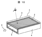
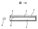
 まず従来における腐食環境モニタリング装置の構成例を図10~12に示して説明する。図10は従来の腐食環境モニタリング装置の斜視図、図11は従来の腐食環境モニタリング装置の上面図、図12は図11のB-B断面図である。 First, a configuration example of a conventional corrosion environment monitoring apparatus will be described with reference to FIGS. 10 is a perspective view of a conventional corrosive environment monitoring apparatus, FIG. 11 is a top view of the conventional corrosive environment monitoring apparatus, and FIG. 12 is a cross-sectional view taken along line BB of FIG.
 図10の斜視図に示すように腐食環境モニタリング装置1は、箱型形状の中央部に一方端が閉止され、他方端が開口部5とされた通路構造4を形成している。また通路構造4を構成する側面、上下面、奥面のうち、上面を金属薄膜2で形成し、さらに金属薄膜2を透明基板3で覆っている。これにより金属薄膜2の腐食具合が腐食環境モニタリング装置1の上方から目視可能とされている。 As shown in the perspective view of FIG. 10, the corrosive environment monitoring apparatus 1 forms a passage structure 4 having one end closed at the center of the box shape and the other end being an opening 5. In addition, the upper surface of the side surface, upper and lower surfaces, and rear surface constituting the passage structure 4 is formed with the metal thin film 2, and the metal thin film 2 is covered with the transparent substrate 3. Thereby, the corrosion state of the metal thin film 2 is visible from above the corrosion environment monitoring device 1.
 この構造によれば、金属薄膜2がセンサ部を構成しており、開口部5を有する通路構造4内の一部の壁面(図10の場合には上面)に取付けられている。また金属薄膜2の成膜面が通路構造4側で、透明基板3が周囲雰囲気側になるように、すなわち透明基板3を通して金属薄膜2を周囲雰囲気側(図10では上側)から観察できるように取り付けられている。金属薄膜2には、電気電子装置設置環境の腐食環境モニタリングに使用されている銅、銀に加えて、アルミニウム、鉄、亜鉛など、金属と腐食生成物の色調が異なる金属を用いることができる。 According to this structure, the metal thin film 2 constitutes a sensor portion, and is attached to a part of the wall surface (upper surface in the case of FIG. 10) in the passage structure 4 having the opening 5. Further, the metal thin film 2 can be observed from the ambient atmosphere side (upper side in FIG. 10) so that the film formation surface of the metal thin film 2 is on the passage structure 4 side and the transparent substrate 3 is on the ambient atmosphere side. It is attached. For the metal thin film 2, in addition to copper and silver used for monitoring the corrosive environment of the installation environment of the electric and electronic device, a metal having a different color tone from the metal and the corrosion product such as aluminum, iron and zinc can be used.
 従来の腐食環境モニタリング装置1を環境中に暴露すると、環境中に存在する腐食性物質6は通路構造4の開口部5から侵入して、金属薄膜2を腐食させる。この場合に通路構造4は、環境中に存在する腐食性物質6によるセンサ部である金属薄膜部2の腐食速度を制御する役割をもつ。通路構造4は、開口部5が一つであり(図11、12で通路構造の左側)、通路構造の右側には開口部はなく周囲環境から遮断されている。ここで腐食性物質は、腐食性ガス、飛来海塩、塵埃などがあるが、以下腐食性ガスを代表として述べる。 When the conventional corrosion environment monitoring device 1 is exposed to the environment, the corrosive substance 6 existing in the environment enters from the opening 5 of the passage structure 4 and corrodes the metal thin film 2. In this case, the passage structure 4 has a role of controlling the corrosion rate of the metal thin film portion 2 which is a sensor portion due to the corrosive substance 6 present in the environment. The passage structure 4 has one opening 5 (the left side of the passage structure in FIGS. 11 and 12), and there is no opening on the right side of the passage structure and is isolated from the surrounding environment. Here, the corrosive substances include corrosive gas, flying sea salt, dust, etc., but the corrosive gas will be described below as a representative.
 図11の上面図によれば、一方端が閉止(図の右側)されたことで通路構造4は通風路とならないために、環境中に存在する腐食性ガス6は通路構造4の開口部5から時間経過とともに徐々に侵入してくる。この図で6’は通路構造4内に進入した腐食性ガス6を表しており、図11のB-B断面を示す図12によれば内部侵入した腐食性物質6’が開口部5側の金属薄膜2に接触する。 According to the top view of FIG. 11, the corrosive gas 6 present in the environment is removed from the opening 5 of the passage structure 4 because the passage structure 4 does not become a ventilation path when one end is closed (right side in the figure). Gradually invades over time. In this figure, 6 'represents the corrosive gas 6 that has entered the passage structure 4, and according to FIG. 12 showing the BB cross section of FIG. 11, the corrosive substance 6' that has entered inside is on the opening 5 side. Contact the metal thin film 2.
 つぎに、従来の腐食環境モニタリング装置1により通路構造4内に侵入し、拡散した開口部5近傍の腐食性ガス6’を定量化する方法について述べる。 Next, a method for quantifying the corrosive gas 6 'in the vicinity of the opening 5 that has entered the passage structure 4 and diffused by the conventional corrosive environment monitoring apparatus 1 will be described.
 図10の腐食環境モニタリング装置1では、腐食性ガス6’の拡散を紙面左からの方向に限定して、腐食環境モニタリング装置1上での腐食を制御している。開口部5からの距離が近い程腐食性ガス6’の濃度流束は大きいため、金属薄膜2では、開口部5に近い左側ほど腐食量が大きくなる。この挙動は、例えば「硫黄ガス環境での銀の腐食速度の推定」材料と環境第56巻、p265-271(2007)に記載されている。この文献では、腐食性ガス6’の発生源から離れるに従い腐食速度が減少することを金属板による実験および解析で求めている。この手法を用いることで、腐食環境モニタリング装置の腐食挙動を解析することができる。 In the corrosive environment monitoring apparatus 1 in FIG. 10, the corrosion on the corrosive environment monitoring apparatus 1 is controlled by limiting the diffusion of the corrosive gas 6 'to the direction from the left side of the drawing. Since the concentration flux of the corrosive gas 6 ′ is larger as the distance from the opening 5 is shorter, in the metal thin film 2, the amount of corrosion increases toward the left side closer to the opening 5. This behavior is described, for example, in "Estimation of Silver Corrosion Rate in Sulfur Gas Environment" Material and Environment Vol. 56, p265-271 (2007). In this document, it is required by experiments and analyzes using a metal plate that the corrosion rate decreases as the distance from the source of the corrosive gas 6 'increases. By using this method, the corrosion behavior of the corrosion environment monitoring device can be analyzed.
 ここでは金属薄膜2を使用しているため、腐食厚さが金属薄膜2の厚さと同じになった領域(透明基板3との界面まで金属薄膜2が腐食した領域)で腐食の進行は止まる。この金属薄膜2の領域を、透明基板3側から観察すると、金属薄膜2の金属の色調から腐食生成物の色調に変化していることを確認できる。 Here, since the metal thin film 2 is used, the progress of the corrosion stops in a region where the corrosion thickness is the same as the thickness of the metal thin film 2 (a region where the metal thin film 2 corrodes to the interface with the transparent substrate 3). When the region of the metal thin film 2 is observed from the transparent substrate 3 side, it can be confirmed that the color tone of the metal thin film 2 is changed to the color tone of the corrosion product.
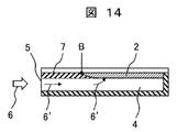
 腐食環境モニタリング装置1の暴露後の金属薄膜2の腐食状況を図13の上面図や図14のB-B断面図に示す。図13によれば、金属薄膜2の腐食の進行により腐食厚さが薄膜厚さと同じになった領域(基板との界面まで金属薄膜が腐食した領域)では、それ以上腐食は進行しない。環境中に存在する腐食性ガス6は開口部5に近い左側から拡散し続けてさらに右側の金属薄膜を腐食させる。図13の上面図や図14のB-B断面図に示すように、膜厚方向全てが腐食した金属薄膜2の領域7(図中左端からB点までの距離)は、暴露時間の経過とともに右側に広がる。 The corrosion state of the metal thin film 2 after exposure to the corrosion environment monitoring device 1 is shown in the top view of FIG. 13 and the BB cross-sectional view of FIG. According to FIG. 13, in the region where the corrosion thickness becomes the same as the thin film thickness due to the progress of the corrosion of the metal thin film 2 (the region where the metal thin film corroded to the interface with the substrate), the corrosion does not proceed any further. The corrosive gas 6 present in the environment continues to diffuse from the left side close to the opening 5 and further corrodes the metal film on the right side. As shown in the top view of FIG. 13 and the BB cross-sectional view of FIG. 14, the region 7 (distance from the left end to the point B in the figure) of the metal thin film 2 that has been corroded in all the film thickness directions is shown as the exposure time elapses. Spread to the right.
 ASHRAEガイドラインでは、1ヶ月間暴露した金属の腐食生成物の厚さにより環境の腐食性を診断する。暴露した金属の腐食生成物の厚さは、従来技術により腐食環境モニタリング装置で膜厚方向全てが腐食した金属薄膜の領域7の長さから換算できる。膜厚方向全てが腐食した金属薄膜の領域7の長さの伸長速度は、金属薄膜の厚さと開口部の高さに依存する。その伸長速度は、金属薄膜が薄いほど、開口部が高いほど早い。 In the ASHRAE guidelines, the corrosiveness of the environment is diagnosed based on the thickness of metal corrosion products exposed for one month. The thickness of the exposed corrosion product of the metal can be converted from the length of the region 7 of the metal thin film that has been corroded in the film thickness direction by the conventional corrosion environment monitoring device. The extension rate of the length of the region 7 of the metal thin film that is corroded in the whole film thickness direction depends on the thickness of the metal thin film and the height of the opening. The elongation rate is faster as the metal thin film is thinner and the opening is higher.
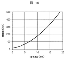
 腐食環境モニタリング装置1で膜厚方向全てが腐食した金属薄膜2の領域7の長さと暴露した金属板の腐食生成物の厚さの関係の一例を図15に示す。図15は、横軸に変色した領域7の長さをとり、縦軸に暴露した金属板の腐食生成物の厚さを示したものであり、具体的には銀薄膜厚さ20nm、通路高さ2mm、通路幅5mm、通路長さ20mmとしたときの特性を示している。 FIG. 15 shows an example of the relationship between the length of the region 7 of the metal thin film 2 corroded in the film thickness direction by the corrosion environment monitoring apparatus 1 and the thickness of the corrosion product of the exposed metal plate. FIG. 15 shows the thickness of the discolored region 7 on the horizontal axis and the thickness of the corrosion product of the exposed metal plate on the vertical axis. Specifically, the thickness of the silver thin film is 20 nm, the passage height is shown. The characteristics when the length is 2 mm, the passage width is 5 mm, and the passage length is 20 mm are shown.
 この特性によれば、曲線の傾きは比較的大きく、腐食した金属薄膜の領域7の長さがわずかに伸長しても暴露した金属板の腐食生成物の厚さが大きく増大する(測定精度が低い)ことがわかる。暴露した金属板の腐食生成物の厚さを精度良く求めるためには、曲線の傾きの小さい(腐食した金属薄膜の領域7の長さが大きく伸長しても暴露した金属板の腐食生成物の厚さがわずかに増大する)腐食環境モニタリング装置が必要である。 According to this characteristic, the slope of the curve is relatively large, and even if the length of the corroded metal thin film region 7 is slightly elongated, the thickness of the corrosion product of the exposed metal plate is greatly increased (measurement accuracy is increased). Low). In order to accurately determine the thickness of the corrosion product of the exposed metal plate, the curve slope is small (even if the length of the corroded metal thin film region 7 is greatly extended, the corrosion product of the exposed metal plate Corrosion environment monitoring equipment (thickness increases slightly) is required.
 なおASHRAEガイドラインでは1ヶ月間暴露した金属の腐食生成物の厚さにより、またISO11844-1規格では1年間暴露した金属の腐食生成物の厚さにより環境の腐食性を診断する。 In the ASHRAE guidelines, the corrosiveness of the environment is diagnosed based on the thickness of the corrosion product of the metal exposed for one month, and in the ISO 11844-1 standard, the thickness of the corrosion product of the metal exposed for one year.
 このため、両方の規格に適用できる腐食環境モニタリング装置が必要とされている。 Therefore, a corrosion environment monitoring device that is applicable to both standards is required.
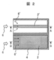
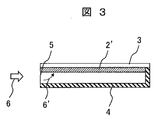
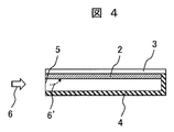
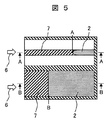
 以上、従来における腐食環境モニタリング装置の構成と課題が明確になったことから、以下に本発明の腐食環境モニタリング装置の構成について説明する。本発明の実施例1に係る腐食環境モニタリング装置の構成例と作用を図1~図7に示す。図1は本発明の実施例1に係る腐食環境モニタリング装置の全体構成を示す斜視図、図2はその上面図、図3は図2のA-A断面図、図4は図2のB-B断面図である。また図5、図6、図7は、実施例1の腐食環境モニタリング装置の暴露後における金属薄膜の腐食状況を示す上面図、図5の腐食環境モニタリング装置のA-A断面図、図5の腐食環境モニタリング装置のB-B断面図をそれぞれ表している。 As described above, since the configuration and problems of the conventional corrosion environment monitoring device have been clarified, the configuration of the corrosion environment monitoring device of the present invention will be described below. A configuration example and an operation of the corrosive environment monitoring apparatus according to the first embodiment of the present invention are shown in FIGS. 1 is a perspective view showing the overall configuration of a corrosive environment monitoring apparatus according to Embodiment 1 of the present invention, FIG. 2 is a top view thereof, FIG. 3 is a cross-sectional view taken along line AA in FIG. 2, and FIG. It is B sectional drawing. 5, FIG. 6 and FIG. 7 are top views showing the corrosion state of the metal thin film after the exposure of the corrosion environment monitoring apparatus of Example 1, AA sectional view of the corrosion environment monitoring apparatus of FIG. BB sectional views of the corrosion environment monitoring device are shown respectively.
 図1の本発明の実施例1に係る腐食環境モニタリング装置1を図10の従来の腐食環境モニタリング装置1と比較して明らかなように、実施例1の腐食環境モニタリング装置1では腐食環境モニタリング部を複数組(図1では2組)設けている。かつ腐食環境モニタリング部における腐食検知条件が相違するものとされている。図1の実施例1では、センサ部である金属薄膜2について、図10と同じ条件(通路構造4の上面全体を金属薄膜で覆う)の第1の金属薄膜2と、異なる条件(通路構造4の上面の一部に奥行き方向に金属薄膜を配置)の第2の金属薄膜2’を設けたものである。なおその他の条件(痛風構造4の構造、腐食性ガス6など)は同じとされている。 As apparent from the comparison of the corrosive environment monitoring apparatus 1 according to the first embodiment of the present invention shown in FIG. 1 with the conventional corrosive environment monitoring apparatus 1 shown in FIG. A plurality of sets (two sets in FIG. 1) are provided. In addition, the corrosion detection conditions in the corrosion environment monitoring section are different. In Example 1 of FIG. 1, about the metal thin film 2 which is a sensor part, it differs from the 1st metal thin film 2 of the same conditions (covering the whole upper surface of the channel | path structure 4 with a metal thin film) as FIG. The second metal thin film 2 ′ is provided on a part of the upper surface of the metal thin film in the depth direction. Other conditions (the structure of the gout structure 4, the corrosive gas 6, etc.) are the same.
 さらに具体的に説明する。腐食環境モニタリング装置1には、透明基板3上に付設した金属薄膜2、2’からなるセンサ部がある。金属薄膜2は通路構造4と同じ幅であり、金属薄膜2’は通路構造4より狭い幅である。 More specifically. The corrosive environment monitoring apparatus 1 has a sensor unit composed of metal thin films 2, 2 ′ provided on a transparent substrate 3. The metal thin film 2 has the same width as the passage structure 4, and the metal thin film 2 ′ is narrower than the passage structure 4.
 実施例1の構成の場合に、図2の上面図に示したように、腐食性ガス6’の流れは、金属薄膜2の通路構造では腐食性ガス6’は通路構造と平行な方向に拡散して金属薄膜と反応するのに対し、金属薄膜2’の通路構造では腐食性ガス6’は通路構造と平行な方向とともに垂直方向に拡散(金属薄膜2の側面から拡散)する。 In the case of the configuration of the first embodiment, as shown in the top view of FIG. 2, the corrosive gas 6 ′ diffuses in the direction parallel to the passage structure in the passage structure of the metal thin film 2. In contrast, the corrosive gas 6 ′ diffuses in the vertical direction as well as in the direction parallel to the passage structure (diffuses from the side surface of the metal thin film 2) in the passage structure of the metal thin film 2 ′.
 このため、実施例1の腐食環境モニタリング装置の暴露後における金属薄膜の腐食状況を示す図5に示しているように、同じ厚さの金属薄膜でも、金属薄膜2’の変色領域の長さ(図5の左端からA点までの距離)のほうが、金属薄膜2の変色領域の長さ(図5の左端からB点までの距離)に比べて長いという腐食結果が得られる。このことについてさらに詳細に説明する。 For this reason, as shown in FIG. 5 which shows the corrosion state of the metal thin film after the exposure of the corrosion environment monitoring apparatus of Example 1, the length of the discoloration region of the metal thin film 2 ′ ( The corrosion result is obtained that the distance from the left end of FIG. 5 to the point A) is longer than the length of the discolored region of the metal thin film 2 (the distance from the left end to the point B in FIG. 5). This will be described in more detail.
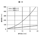
 図8は、図15と同様に腐食環境モニタリング装置1で膜厚方向全てが腐食した金属薄膜2の領域7の長さと暴露した金属板の腐食生成物の厚さの関係の一例を示した図であるが、広幅センサ(金属薄膜2)と狭幅センサ(金属薄膜2’)における特性の相違を対比して示している。 FIG. 8 is a diagram showing an example of the relationship between the length of the region 7 of the metal thin film 2 corroded in the film thickness direction by the corrosion environment monitoring apparatus 1 and the thickness of the corrosion product of the exposed metal plate in the same manner as FIG. However, the difference in characteristics between the wide sensor (metal thin film 2) and the narrow sensor (metal thin film 2 ') is shown in comparison.
 図8の事例は、狭幅金属薄膜2’について、銀薄膜幅1mm、銀薄膜厚さ20nm、通路高さ2mm、通路幅20mm、通路長さ20mmとし、広幅金属薄膜2について、銀薄膜幅5mm、銀薄膜厚さ20nm、通路高さ2mm、通路幅5mm、通路長さ20mmとして計測した結果を示している。このように幅の異なる金属薄膜を採用すると、狭幅の金属薄膜2’でASHRAEガイドライン向けに1ヶ月間暴露した金属の腐食生成物の厚さを求め、広幅の金属薄膜2でISO11844-1規格では1年間暴露した金属の腐食生成物の厚さを求めることができる。 In the case of FIG. 8, the narrow metal thin film 2 ′ has a silver thin film width of 1 mm, a silver thin film thickness of 20 nm, a passage height of 2 mm, a passage width of 20 mm, and a passage length of 20 mm. The results are shown in which the silver thin film thickness is 20 nm, the passage height is 2 mm, the passage width is 5 mm, and the passage length is 20 mm. When using thin metal films with different widths, the thickness of the metal corrosion product exposed for one month for the ASHRAE guideline with the narrow metal thin film 2 ′ is obtained. With the wide metal thin film 2, the ISO 11844-1 standard is obtained. Then, the thickness of the corrosion product of the metal exposed for one year can be obtained.
 この図8の関係から、金属薄膜2を通路構造4より狭い幅とするにあたり、狭幅金属薄膜2’は広幅金属薄膜2に比べて1/5以下の幅で構成することが好ましい。これによりASHRAEガイドラインにおける1ヶ月間暴露やISO11844-1規格における1年間暴露した金属の腐食度合いをともに測定することができる。 From the relationship shown in FIG. 8, it is preferable that the narrow metal thin film 2 ′ has a width of 1/5 or less than the wide metal thin film 2 when the metal thin film 2 is narrower than the passage structure 4. This makes it possible to measure both the degree of corrosion of metals exposed for one month in the ASHRAE guidelines and exposed for one year in the ISO 11844-1 standard.
 このように本発明の腐食環境モニタリング装置1では、2種類の金属薄膜2、2’を使用しているため、2種類の方法で腐食生成物の厚さを求めて平均値を求めることができる。さらに広幅金属薄膜の変色領域の長さに対する狭幅金属薄膜の変色領域の長さの比を算出し、この値から腐食生成物の厚さを求めることができる。さらに本発明の腐食環境モニタリング装置1では、3種類の方法で腐食生成物の厚さを求め平均化することで、精度よく腐食生成物の厚さを推定できる。 Thus, since the corrosion environment monitoring apparatus 1 of the present invention uses the two types of metal thin films 2 and 2 ', the average value can be obtained by obtaining the thickness of the corrosion product by two types of methods. . Furthermore, the ratio of the length of the discolored region of the narrow metal thin film to the length of the discolored region of the wide metal thin film is calculated, and the thickness of the corrosion product can be obtained from this value. Furthermore, in the corrosion environment monitoring apparatus 1 of the present invention, the thickness of the corrosion product is obtained and averaged by three kinds of methods, so that the thickness of the corrosion product can be estimated with high accuracy.
 ここで、広幅金属薄膜2の変色領域7の長さに対する狭幅金属薄膜2’の変色領域7の長さの比から腐食生成物の厚さを求める方法を説明する。金属薄膜の変色領域の長さと腐食厚さの関係は、図8で示したとおり、通路構造の幅に対して金属薄膜の幅が狭くなるに従い線形性を、反対に通路構造の幅に対して金属薄膜の幅が等しくなると非線形性を示すことがわかった。この線形性の違いを利用すれば、広幅金属薄膜の変色領域の長さに対する狭幅金属薄膜の変色領域の長さの比から腐食生成物の厚さを求めることができる。 Here, a method for obtaining the thickness of the corrosion product from the ratio of the length of the color change region 7 of the narrow metal thin film 2 ′ to the length of the color change region 7 of the wide metal thin film 2 will be described. As shown in FIG. 8, the relationship between the length of the discoloration region of the metal thin film and the corrosion thickness shows linearity as the width of the metal thin film becomes narrower with respect to the width of the passage structure, and conversely with respect to the width of the passage structure. It was found that nonlinearity was exhibited when the widths of the metal thin films were equal. By utilizing this difference in linearity, the thickness of the corrosion product can be obtained from the ratio of the length of the color change region of the narrow metal thin film to the length of the color change region of the wide metal thin film.
 図8から求めた広幅金属薄膜の変色領域の長さに対する狭幅金属薄膜の変色領域の長さの比と腐食厚さの関係の例を、図9に示す。腐食厚さの絶対量が少ない範囲で、変色領域の長さの比と腐食厚さは良い直線関係を有している。この方法は、腐食生成物の厚さを精度良く推定するのに好適な方法である。 FIG. 9 shows an example of the relationship between the ratio of the length of the discolored region of the narrow metal thin film to the length of the discolored region of the wide metal thin film obtained from FIG. 8 and the corrosion thickness. In the range where the absolute amount of the corrosion thickness is small, the ratio of the length of the discoloration region and the corrosion thickness have a good linear relationship. This method is suitable for accurately estimating the thickness of the corrosion product.
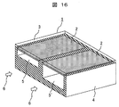
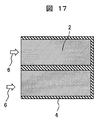
 本発明の実施例2に係る腐食環境モニタリング装置の構成例を図16~17に示す。図16は斜視図、図17は上面図である。 16 to 17 show configuration examples of the corrosion environment monitoring apparatus according to Example 2 of the present invention. 16 is a perspective view, and FIG. 17 is a top view.
 図16の本発明の実施例2に係る腐食環境モニタリング装置1を図1の実施例1の腐食環境モニタリング装置1と比較して明らかなように、同じ構成の金属薄膜を複数組(図16では2組)設けている点で共通するが、腐食環境モニタリング部における腐食検知条件として通路構造4、従って開口部5の大きさが相違するものとされている。 As is apparent from the comparison of the corrosive environment monitoring apparatus 1 according to the second embodiment of the present invention shown in FIG. 16 with the corrosive environment monitoring apparatus 1 according to the first embodiment shown in FIG. The two structures are common in that they are provided, but the size of the passage structure 4 and hence the opening 5 are different as corrosion detection conditions in the corrosion environment monitoring section.
 さらに具体的に説明する。腐食環境モニタリング装置1には、透明基板3上に付設した二組の金属薄膜2からなるセンサ部が配置されている。金属薄膜2はともに通路構造4と同じ幅である。ただし、通路構造4の開口部5と5’の高さが異なる構造である。 More specifically. In the corrosive environment monitoring apparatus 1, a sensor unit composed of two sets of metal thin films 2 provided on a transparent substrate 3 is arranged. Both metal thin films 2 have the same width as the passage structure 4. However, the openings 5 and 5 'of the passage structure 4 are different in height.
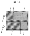
 この場合の、腐食環境モニタリング装置1の暴露後の金属薄膜の腐食状況を図18の上面図に示す。開口部5の通路に対し、開口部5’の通路では腐食性ガス6は開口部5’が広い分だけ通路内部にまで拡散する。このため、同じ厚さの金属薄膜2でも、開口部5’の変色領域の長さ(図18の左端からA点までの距離)のほうが、開口部5の変色領域の長さ(図18の左端からB点までの距離)に比べて長いという計測結果が得られる。 In this case, the corrosion state of the metal thin film after the exposure by the corrosion environment monitoring apparatus 1 is shown in the top view of FIG. In contrast to the passage of the opening 5, the corrosive gas 6 in the passage of the opening 5 'diffuses to the inside of the passage by the wider opening 5'. For this reason, even in the metal thin film 2 having the same thickness, the length of the color changing region of the opening 5 ′ (the distance from the left end of FIG. 18 to the point A) is longer than the length of the color changing region of the opening 5 (FIG. 18). A measurement result is obtained that is longer than the distance from the left end to point B).
 図19に金属薄膜の変色領域の長さと腐食厚さの関係の一例を示している。これは、高通路構造について、銀薄膜厚さ20nm、通路高さ10mm、通路幅5mm、通路長さ20mmとし、低通路構造について銀薄膜厚さ20nm、通路高さ2mm、通路幅5mm、通路長さ20mmとして計測を行った結果である。このように高さの異なる開口部を採用すると、高開口部5’でASHRAEガイドライン向けに1ヶ月間暴露した金属の腐食生成物の厚さを求め、低開口部5でISO11844-1規格では1年間暴露した金属の腐食生成物の厚さを求めることができる。 FIG. 19 shows an example of the relationship between the length of the discolored region of the metal thin film and the corrosion thickness. For the high passage structure, the silver thin film thickness is 20 nm, the passage height is 10 mm, the passage width is 5 mm, and the passage length is 20 mm. For the low passage structure, the silver thin film thickness is 20 nm, the passage height is 2 mm, the passage width is 5 mm, and the passage length. This is a result of measurement with a thickness of 20 mm. If openings having different heights are employed in this way, the thickness of the metal corrosion product exposed for one month for the ASHRAE guidelines at the high opening 5 ′ is obtained, and the thickness of the low opening 5 is 1 in the ISO 11844-1 standard. The thickness of the metal corrosion products exposed over the years can be determined.
 実施例2の腐食環境モニタリング装置1では、2種類の開口部を使用しているため、2種類の方法で腐食生成物の厚さを求めて平均値を求めることができる。さらに2種類の金属薄膜を使用しているため、低開口部(広開口部)の変色領域の長さに対する高開口部(狭開口部)の変色領域の長さの比を算出し、この値から腐食生成物の厚さを求めることができる。さらに実施例2の腐食環境モニタリング装置1では、3種類の方法で腐食生成物の厚さを求め平均化することで、精度よく腐食生成物の厚さを推定できる。 Since the corrosion environment monitoring apparatus 1 of Example 2 uses two types of openings, the average value can be obtained by determining the thickness of the corrosion product by two types of methods. Furthermore, since two types of metal thin films are used, the ratio of the length of the discoloration region of the high opening (narrow opening) to the length of the discoloration region of the low opening (wide opening) is calculated, and this value is calculated. From this, the thickness of the corrosion product can be determined. Furthermore, in the corrosion environment monitoring apparatus 1 of Example 2, the thickness of the corrosion product can be accurately estimated by obtaining and averaging the thickness of the corrosion product by three types of methods.
 ここで、高開口部の変色領域の長さに対する低開口部の変色領域の長さの比から腐食生成物の厚さを求める方法を説明すると、この理由は前述の狭金属薄膜と広金属薄膜の方法と同様である。金属薄膜の変色領域の長さと腐食厚さの関係は、図19で示したとおり、開口部が高くなるに従い線形性を、反対に開口部が低くなると非線形性を示すことがわかった。この線形性の違いを利用すれば、低開口部の変色領域の長さに対する高開口部の変色領域の長さの比から腐食生成物の厚さを求めることができる。 Here, the method for obtaining the thickness of the corrosion product from the ratio of the length of the color change region of the low opening to the length of the color change region of the high opening will be explained. It is the same as the method. As shown in FIG. 19, it was found that the relationship between the length of the discoloration region of the metal thin film and the corrosion thickness shows linearity as the opening becomes higher and, on the contrary, non-linearity when the opening becomes lower. By utilizing this difference in linearity, the thickness of the corrosion product can be obtained from the ratio of the length of the color change region of the high opening to the length of the color change region of the low opening.
 さらに図19から求めた低開口部の金属薄膜の変色領域の長さに対する高開口部の金属薄膜の変色領域の長さの比と腐食厚さの関係の例を、図20に示す。これによれば、腐食厚さの絶対量が少ない範囲で、変色領域の長さの比と腐食厚さは良い直線関係を有している。この方法は、腐食生成物の厚さを精度良く推定するのに好適な方法である。 Further, FIG. 20 shows an example of the relationship between the ratio of the length of the color change region of the metal thin film in the high opening portion to the length of the color change region of the metal thin film in the low opening portion obtained from FIG. 19 and the corrosion thickness. According to this, in the range where the absolute amount of the corrosion thickness is small, the ratio of the length of the discolored region and the corrosion thickness have a good linear relationship. This method is suitable for accurately estimating the thickness of the corrosion product.
 本発明の実施例3に係る腐食環境モニタリング装置の構成例を図21に示す。図21は、実施例1の広狭幅金属薄膜の関係と、実施例2の高低開口部の関係を併用した方式である。 FIG. 21 shows a configuration example of the corrosion environment monitoring apparatus according to Example 3 of the present invention. FIG. 21 shows a system in which the relationship between the wide and narrow metal thin film of Example 1 and the relationship between the height openings of Example 2 are used together.
 ここでは、実施例2の開口部の高さが異なる通路構造と異なる幅の金属薄膜を組み合わせて、高開口部の通路に狭幅金属薄膜を付設したセンシング部と、低開口部の通路に広幅金属薄膜を付設したセンシング部を有する装置を構成する。 Here, a combination of a passage structure having a different opening height in Example 2 and a metal thin film having a different width, a sensing portion in which a narrow metal thin film is attached to a passage in a high opening portion, and a wide opening in a passage in a low opening portion. An apparatus having a sensing unit provided with a metal thin film is configured.
 これにより、変色領域の長さの比と腐食厚さの良い直線関係を維持できるうえ、低開口部の通路に広幅金属薄膜を付設したセンシング部でASHRAEガイドライン向けに1ヶ月間暴露した金属の腐食生成物の厚さを求め、低開口部の通路に広幅金属薄膜を付設したセンシング部でISO11844-1規格では1年間暴露した金属の腐食生成物の厚さを求めることができる。 As a result, the linear relationship between the length ratio of the discolored region and the corrosion thickness can be maintained, and the corrosion of the metal exposed to the ASHRAE guideline for one month in the sensing section with a wide metal thin film attached to the passage of the low opening. The thickness of the product can be obtained, and the thickness of the corrosion product of the metal exposed for one year can be obtained according to the ISO 11844-1 standard in the sensing part in which the wide metal thin film is attached to the passage of the low opening.
 本発明の実施例4に係る腐食環境モニタリング装置の構成例を図22に示す。図22は、実施例1の広狭幅金属薄膜の関係と、実施例2の高低開口部の関係を併用した方式である。 FIG. 22 shows a configuration example of the corrosive environment monitoring apparatus according to Example 4 of the present invention. FIG. 22 shows a system in which the relationship between the wide and narrow metal thin film of Example 1 and the relationship between the high and low openings of Example 2 are used together.
 実施例4では、腐食環境モニタリング装置1には、透明基板3上に付設した金属薄膜2、2’からなるセンサ部がある。金属薄膜2は通路構造4と同じ幅であり、金属薄膜2’は通路構造4より狭い幅である。ここで金属薄膜2’は開口部の側壁面に接するように付設する。 In Example 4, the corrosive environment monitoring apparatus 1 has a sensor unit composed of the metal thin films 2 and 2 ′ provided on the transparent substrate 3. The metal thin film 2 has the same width as the passage structure 4, and the metal thin film 2 ′ is narrower than the passage structure 4. Here, the metal thin film 2 'is attached so as to be in contact with the side wall surface of the opening.
 これにより金属薄膜2を開口部の中央に付設する構造に比べて、側壁面に接するように付設することで実質2倍の幅を有する構造と同等の効果が得ら、環境モニタリング装置の省スペース化に貢献できる。 As a result, compared to the structure in which the metal thin film 2 is attached to the center of the opening, by attaching the metal thin film 2 so as to be in contact with the side wall surface, an effect equivalent to that of a structure having substantially double the width can be obtained. Can contribute to
1:腐食環境モニタリング装置,2、2’:金属薄膜,3:透明基板,4:通路構造,5:開口部,6、6’:腐食性ガス,7:膜厚方向全てが腐食した金属薄膜の領域 1: Corrosion environment monitoring device, 2, 2 ′: Metal thin film, 3: Transparent substrate, 4: Passage structure, 5: Opening, 6, 6 ′: Corrosive gas, 7: Metal thin film corroded in all film thickness directions Area

Claims (10)

  1.  箱型形状の一方端が閉止され、他方端が開口部とされた通路構造の、前記開口部に対する上下面または側面の一部面に金属薄膜2を配置し、該金属薄膜を透明基板で覆って形成されたセンサ部を備える腐食環境モニタリング装置であって、
     腐食環境モニタリング装置は、前記開口部が隣接して配置された複数の腐食環境モニタリング部を備え、複数の腐食環境モニタリング部における前記金属薄膜の腐食検知条件が相違するようにされたことを特徴とする腐食環境モニタリング装置。
    The metal thin film 2 is arranged on the upper and lower surfaces or a part of the side surface of the passage structure in which one end of the box shape is closed and the other end is an opening, and the metal thin film is covered with a transparent substrate. Corrosion environment monitoring device comprising a sensor unit formed by
    The corrosive environment monitoring device includes a plurality of corrosive environment monitoring units in which the openings are arranged adjacent to each other, and the corrosion detection conditions of the metal thin film in the plural corrosive environment monitoring units are different. Corrosion environment monitoring device.
  2.  請求項1に記載の腐食環境モニタリング装置であって、
     前記金属薄膜の腐食検知条件を相違させるために、前記通路構造の奥行き方向に対する前記金属薄膜の幅が相違するようにされたことを特徴とする腐食環境モニタリング装置。
    The corrosion environment monitoring device according to claim 1,
    In order to make the corrosion detection conditions of the metal thin film different, the width of the metal thin film with respect to the depth direction of the passage structure is made different.
  3.  請求項1に記載の腐食環境モニタリング装置であって、
     前記金属薄膜の腐食検知条件を相違させるために、前記通路構造の開口部面積が相違するようにされたことを特徴とする腐食環境モニタリング装置。
    The corrosion environment monitoring device according to claim 1,
    The corrosion environment monitoring apparatus according to claim 1, wherein the opening area of the passage structure is made different in order to make the conditions for detecting corrosion of the metal thin film different.
  4.  請求項1に記載の腐食環境モニタリング装置であって、
     前記金属薄膜の腐食検知条件を相違させるために、前記通路構造の奥行き方向に対する前記金属薄膜の幅が相違するようにされるとともに、前記通路構造の開口部面積が相違するようにされたことを特徴とする腐食環境モニタリング装置。
    The corrosion environment monitoring device according to claim 1,
    In order to make the corrosion detection conditions of the metal thin film different, the width of the metal thin film with respect to the depth direction of the passage structure is made different, and the opening area of the passage structure is made different. A characteristic corrosion environment monitoring device.
  5.  請求項2に記載の腐食環境モニタリング装置であって、
     前記腐食環境モニタリング部における前記金属薄膜の幅は、その比が1/5以下の金属薄膜で構成されることを特徴とする腐食環境モニタリング装置。
    The corrosion environment monitoring device according to claim 2,
    The corrosion environment monitoring apparatus, wherein the width of the metal thin film in the corrosion environment monitoring unit is composed of a metal thin film having a ratio of 1/5 or less.
  6.  請求項3に記載の腐食環境モニタリング装置であって、
     前記腐食環境モニタリング部における前記通路構造の開口部面積は、その比が1/5以下の開口部面積とされることを特徴とする腐食環境モニタリング装置。
    The corrosion environment monitoring device according to claim 3,
    The corrosive environment monitoring device according to claim 1, wherein the opening area of the passage structure in the corrosive environment monitoring unit is an opening area whose ratio is 1/5 or less.
  7.  請求項1から請求項6の何れか1項に記載の腐食環境モニタリング装置であって、
     前記金属薄膜の材料には、銅、銀、金めっき、鉄、鉄ニッケル合金、アルミニウム又は亜鉛のうち少なくとも一つが含まれることを特徴とする腐食環境モニタリング装置。
    The corrosion environment monitoring device according to any one of claims 1 to 6,
    The corrosion environment monitoring apparatus according to claim 1, wherein the material of the metal thin film includes at least one of copper, silver, gold plating, iron, iron-nickel alloy, aluminum, or zinc.
  8.  一つの開口部を有する通路構造と、前記開口部からの腐食性物質の拡散方向と平行な通路構造の一部の壁面が透明基板で形成され、前記透明基板の上に形成した金属薄膜とで構成される第一及び第二の腐食環境モニタリング部を備え、
     前記第一及び第二の腐食環境モニタリング部は、所定の期間に渡り被測定環境中に放置した前記金属薄膜の腐食生成物によって変化した色調の領域の形状寸法について、前記透明基板を通じて測定でき、
     前記第一の腐食環境モニタリング部と前記第二の腐食環境モニタリング部は、各々の開口部の高さが異なる通路構造、もしくは各々の幅が異なる所定の材料の金属薄膜で構成されることを特徴とする腐食環境モニタリング装置。
    A passage structure having one opening, and a metal thin film formed on the transparent substrate, wherein a wall surface of a part of the passage structure parallel to the diffusion direction of the corrosive substance from the opening is formed of a transparent substrate. Comprising a first and second corrosive environment monitoring section configured;
    The first and second corrosion environment monitoring units can measure the shape and size of the color tone region changed by the corrosion product of the metal thin film left in the measurement environment for a predetermined period through the transparent substrate,
    The first corrosive environment monitoring unit and the second corrosive environment monitoring unit are configured with a passage structure having different opening heights or metal thin films of predetermined materials having different widths. Corrosion environment monitoring device.
  9.  一つの開口部を有する通路構造と、前記開口部からの腐食性物質の拡散方向と平行な通路構造の一部の壁面が透明基板で形成され、前記透明基板の上に形成した金属薄膜とで構成される第一及び第二の腐食環境モニタリング部を備え、
     前記第一及び第二の腐食環境モニタリング部は、所定の期間に渡り被測定環境中に放置した前記金属薄膜の腐食生成物によって変化した色調の領域の形状寸法について、前記透明基板を通じて測定でき、
     前記第一の腐食環境モニタリング部は所定の材料で開口部と同じ幅の金属薄膜で構成され、かつ前記第二の腐食環境モニタリング部は前記第一の腐食環境モニタリング部の金属薄膜の材料と同じ材料で開口部より狭い幅の金属薄膜で構成されることを特徴とする腐食環境モニタリング装置。
    A passage structure having one opening, and a metal thin film formed on the transparent substrate, wherein a wall surface of a part of the passage structure parallel to the diffusion direction of the corrosive substance from the opening is formed of a transparent substrate. Comprising a first and second corrosive environment monitoring section configured;
    The first and second corrosion environment monitoring units can measure the shape and size of the color tone region changed by the corrosion product of the metal thin film left in the measurement environment for a predetermined period through the transparent substrate,
    The first corrosion environment monitoring unit is made of a metal thin film having a predetermined material and the same width as the opening, and the second corrosion environment monitoring unit is the same as the material of the metal thin film of the first corrosion environment monitoring unit. Corrosion environment monitoring device characterized by being composed of a metal thin film with a material narrower than the opening.
  10.  一つの開口部を有する通路構造と、前記開口部からの腐食性物質の拡散方向と平行な通路構造の一部の壁面が透明基板で形成され、前記透明基板の上に形成した金属薄膜とで構成される第一及び第二の腐食環境モニタリング部を備え、
    前記第一及び第二の腐食環境モニタリング部は、所定の期間に渡り被測定環境中に放置した前記金属薄膜の腐食生成物によって変化した色調の領域の形状寸法について、前記透明基板を通じて測定でき、
     前記第一の腐食環境モニタリング部と前記第二の腐食環境モニタリング部は、同じ材料での金属薄膜で構成され、前記開口部の高さが異なる構造を有していることを特徴とする腐食環境モニタリング装置。
    A passage structure having one opening, and a metal thin film formed on the transparent substrate, wherein a wall surface of a part of the passage structure parallel to the diffusion direction of the corrosive substance from the opening is formed of a transparent substrate. Comprising a first and second corrosive environment monitoring section configured;
    The first and second corrosion environment monitoring units can measure the shape and size of the color tone region changed by the corrosion product of the metal thin film left in the measurement environment for a predetermined period through the transparent substrate,
    The first corrosive environment monitoring unit and the second corrosive environment monitoring unit are composed of a metal thin film made of the same material, and have a structure in which the height of the opening is different. Monitoring device.
PCT/JP2017/006835 2016-04-08 2017-02-23 Corrosive environment monitoring device WO2017175507A1 (en)

Priority Applications (3)

Application Number Priority Date Filing Date Title
JP2018510264A JP6609038B2 (en) 2016-04-08 2017-02-23 Corrosion environment monitoring device
CN201780022360.3A CN109073533B (en) 2016-04-08 2017-02-23 Corrosion environment monitoring device
EP17778886.6A EP3441745B1 (en) 2016-04-08 2017-02-23 Corrosive environment monitoring device

Applications Claiming Priority (2)

Application Number Priority Date Filing Date Title
JP2016-077716 2016-04-08
JP2016077716 2016-04-08

Publications (1)

Publication Number Publication Date
WO2017175507A1 true WO2017175507A1 (en) 2017-10-12

Family

ID=60001001

Family Applications (1)

Application Number Title Priority Date Filing Date
PCT/JP2017/006835 WO2017175507A1 (en) 2016-04-08 2017-02-23 Corrosive environment monitoring device

Country Status (4)

Country Link
EP (1) EP3441745B1 (en)
JP (1) JP6609038B2 (en)
CN (1) CN109073533B (en)
WO (1) WO2017175507A1 (en)

Cited By (2)

* Cited by examiner, † Cited by third party
Publication number Priority date Publication date Assignee Title
US10330586B2 (en) * 2016-07-20 2019-06-25 Honeywell International Inc. Corrosion monitor
WO2020039611A1 (en) * 2018-08-23 2020-02-27 株式会社日立製作所 Corrosive environment monitoring method and corrosive environment monitoring system

Families Citing this family (1)

* Cited by examiner, † Cited by third party
Publication number Priority date Publication date Assignee Title
CN114236105B (en) * 2021-11-30 2023-11-28 浙江省二建建设集团有限公司 Device and method for monitoring corrosion of concrete on garbage pool wall

Citations (5)

* Cited by examiner, † Cited by third party
Publication number Priority date Publication date Assignee Title
JP2008281499A (en) * 2007-05-14 2008-11-20 Ntn Corp Corrosion environment sensor and sensor system
JP2008304212A (en) * 2007-06-05 2008-12-18 Mitsubishi Heavy Ind Ltd Test piece, and test piece manufacturing method of
WO2013042179A1 (en) * 2011-09-20 2013-03-28 株式会社日立製作所 Corrosion environment monitor device and method
JP2013190241A (en) * 2012-03-13 2013-09-26 Hitachi Ltd Corrosive environment monitoring apparatus
US20130265064A1 (en) * 2012-04-04 2013-10-10 International Business Machines Corporation Corrosion detector apparatus for universal assessment of pollution in data centers

Family Cites Families (5)

* Cited by examiner, † Cited by third party
Publication number Priority date Publication date Assignee Title
US8390306B2 (en) * 2010-08-11 2013-03-05 International Business Machines Corporation Corrosion sensors
CN202533402U (en) * 2012-05-04 2012-11-14 山东电力研究院 Atmospheric environment pollutant corrosion monitoring sensor
CN102645457A (en) * 2012-05-04 2012-08-22 山东电力研究院 Corrosion monitoring sensor for atmospheric environment pollutants
JP6362920B2 (en) * 2014-05-16 2018-07-25 株式会社日立製作所 Corrosion environment monitoring apparatus and method
CN106226226B (en) * 2016-07-11 2019-04-02 国网山东省电力公司电力科学研究院 A kind of atmosphere environment corrosion detection sensor and evaluation method

Patent Citations (5)

* Cited by examiner, † Cited by third party
Publication number Priority date Publication date Assignee Title
JP2008281499A (en) * 2007-05-14 2008-11-20 Ntn Corp Corrosion environment sensor and sensor system
JP2008304212A (en) * 2007-06-05 2008-12-18 Mitsubishi Heavy Ind Ltd Test piece, and test piece manufacturing method of
WO2013042179A1 (en) * 2011-09-20 2013-03-28 株式会社日立製作所 Corrosion environment monitor device and method
JP2013190241A (en) * 2012-03-13 2013-09-26 Hitachi Ltd Corrosive environment monitoring apparatus
US20130265064A1 (en) * 2012-04-04 2013-10-10 International Business Machines Corporation Corrosion detector apparatus for universal assessment of pollution in data centers

Cited By (7)

* Cited by examiner, † Cited by third party
Publication number Priority date Publication date Assignee Title
US10330586B2 (en) * 2016-07-20 2019-06-25 Honeywell International Inc. Corrosion monitor
WO2020039611A1 (en) * 2018-08-23 2020-02-27 株式会社日立製作所 Corrosive environment monitoring method and corrosive environment monitoring system
JP2020030128A (en) * 2018-08-23 2020-02-27 株式会社日立製作所 Corrosion environment monitoring method and corrosion environment monitoring system
CN112543865A (en) * 2018-08-23 2021-03-23 株式会社日立制作所 Corrosion environment monitoring method and corrosion environment monitoring system
JP7033034B2 (en) 2018-08-23 2022-03-09 株式会社日立製作所 Corrosion environment monitoring method and corrosion environment monitoring system
US11460394B2 (en) 2018-08-23 2022-10-04 Hitachi, Ltd. Corrosive environment monitoring method and corrosive environment monitoring system
CN112543865B (en) * 2018-08-23 2023-11-07 株式会社日立制作所 Corrosion environment monitoring method and corrosion environment monitoring system

Also Published As

Publication number Publication date
EP3441745A1 (en) 2019-02-13
CN109073533A (en) 2018-12-21
CN109073533B (en) 2021-03-05
EP3441745A4 (en) 2020-01-01
JPWO2017175507A1 (en) 2019-01-31
JP6609038B2 (en) 2019-11-20
EP3441745B1 (en) 2021-04-07

Similar Documents

Publication Publication Date Title
WO2017061182A1 (en) Corrosive environment monitoring device and method
US9568455B2 (en) Corrosive environment monitoring apparatus and method
JP6362920B2 (en) Corrosion environment monitoring apparatus and method
JP3895087B2 (en) Deterioration diagnosis method
JP6609038B2 (en) Corrosion environment monitoring device
JP5798955B2 (en) Corrosion environment monitoring device
US20090216464A1 (en) Integrated in-line oil monitoring apparatus
JP2011027596A (en) Insulation deterioration diagnosis method of insulating material
JP7033034B2 (en) Corrosion environment monitoring method and corrosion environment monitoring system
JP7226417B2 (en) Hydrogen sulfide concentration estimation device
US10151683B2 (en) Corrosion sensor using electrical continuity
JP3602782B2 (en) Degradation degree measuring kit and method for diagnosing deterioration life of electronic circuit board using this deterioration degree measuring kit
JP2013205211A (en) Corrosion sensor, deterioration detection sensor, and deterioration monitor
JPH1090165A (en) Monitoring apparatus for corrosion environment
JP7437286B2 (en) Corrosive environment monitoring system and corrosive environment monitoring method
JP2005257532A (en) Environment diagnosis tool and environment measurement method using the same
JP2006162570A (en) Reference electrode for detecting degree of acidity and basicity of oil
JP2012047590A (en) Method for recognizing corrosion state of steel structure

Legal Events

Date Code Title Description
WWE Wipo information: entry into national phase

Ref document number: 2018510264

Country of ref document: JP

NENP Non-entry into the national phase

Ref country code: DE

WWE Wipo information: entry into national phase

Ref document number: 2017778886

Country of ref document: EP

ENP Entry into the national phase

Ref document number: 2017778886

Country of ref document: EP

Effective date: 20181108

121 Ep: the epo has been informed by wipo that ep was designated in this application

Ref document number: 17778886

Country of ref document: EP

Kind code of ref document: A1