WO2017175459A1 - 縦孔閉塞装置 - Google Patents
縦孔閉塞装置 Download PDFInfo
- Publication number
- WO2017175459A1 WO2017175459A1 PCT/JP2017/003356 JP2017003356W WO2017175459A1 WO 2017175459 A1 WO2017175459 A1 WO 2017175459A1 JP 2017003356 W JP2017003356 W JP 2017003356W WO 2017175459 A1 WO2017175459 A1 WO 2017175459A1
- Authority
- WO
- WIPO (PCT)
- Prior art keywords
- vertical hole
- movable wall
- wall
- weight
- pair
- Prior art date
- Legal status (The legal status is an assumption and is not a legal conclusion. Google has not performed a legal analysis and makes no representation as to the accuracy of the status listed.)
- Ceased
Links
Images







Classifications
-
- E—FIXED CONSTRUCTIONS
- E04—BUILDING
- E04H—BUILDINGS OR LIKE STRUCTURES FOR PARTICULAR PURPOSES; SWIMMING OR SPLASH BATHS OR POOLS; MASTS; FENCING; TENTS OR CANOPIES, IN GENERAL
- E04H9/00—Buildings, groups of buildings or shelters adapted to withstand or provide protection against abnormal external influences, e.g. war-like action, earthquake or extreme climate
- E04H9/14—Buildings, groups of buildings or shelters adapted to withstand or provide protection against abnormal external influences, e.g. war-like action, earthquake or extreme climate against other dangerous influences, e.g. tornadoes, floods
-
- F—MECHANICAL ENGINEERING; LIGHTING; HEATING; WEAPONS; BLASTING
- F24—HEATING; RANGES; VENTILATING
- F24F—AIR-CONDITIONING; AIR-HUMIDIFICATION; VENTILATION; USE OF AIR CURRENTS FOR SCREENING
- F24F13/00—Details common to, or for air-conditioning, air-humidification, ventilation or use of air currents for screening
- F24F13/08—Air-flow control members, e.g. louvres, grilles, flaps or guide plates
- F24F13/10—Air-flow control members, e.g. louvres, grilles, flaps or guide plates movable, e.g. dampers
- F24F13/14—Air-flow control members, e.g. louvres, grilles, flaps or guide plates movable, e.g. dampers built up of tilting members, e.g. louvre
Definitions
- the present invention relates to a vertical hole closing device.
- Japanese Patent No. 2765630 discloses a structure of an underground space as a subway station structure.
- the structure of the underground space is provided with an exhaust port, an intake port, and a staircase that connect the lower underground space (such as a station platform) and the upper ground.
- the present invention has been made to solve the above-described problems, and one object of the present invention is a vertical hole capable of suppressing liquid from flowing into a lower space through the vertical hole. It is to provide an occluding device.
- a vertical hole closing device is provided at an upper part of a vertical hole in which a space is formed in a lower part, and opens a lying position and a vertical hole that close the vertical hole.
- a movable wall rotatable to the standing position, and a biasing member that biases the movable wall to be positioned at the standing position, and the movable wall resists the biasing force of the biasing member due to liquid pressure caused by liquid.
- the “upper part of the vertical hole” includes not only the outer part located above the vertical hole but also the upper part (upper part) inside the vertical hole.
- the liquid pressure includes both a static pressure due to the liquid and a dynamic pressure due to the liquid.
- the vertical hole is formed at the upper part of the vertical hole in which the space is formed at the lower position and the standing position where the vertical hole is opened.
- a movable movable wall is provided, and the movable wall is configured to be rotated to the fall position against the urging force of the urging member by the liquid pressure of the liquid to close the vertical hole. Accordingly, when the liquid pressure due to the liquid is applied to the movable wall due to, for example, water immersion, the vertical hole can be automatically closed by rotating the movable wall to the lying down position. It is possible to prevent the liquid from flowing into the lower space (a space provided with an underground structure or the like) through the.
- the movable wall is configured to be rotated to the upright position by the urging force of the urging member and returned to the upright position to open the vertical hole when the liquid pressure decreases or disappears.
- the vertical wall can be automatically opened by rotating the movable wall to the upright position. Air circulation between the space and the lower space can be automatically resumed.
- the open / close state of the vertical hole can be switched according to the state of the liquid pressure without requiring an artificial operation.
- the vertical hole is provided at an upper portion of the vertical hole, and further includes a standing wall portion having a rectangular shape in plan view, and the movable wall has a rectangular shape in plan view. It arrange
- an upper portion of the vertical hole is provided to be inclined obliquely upward from the movable wall side to the opposite side of the movable wall, and an opening corresponding to the vertical hole is provided.
- the movable wall is further configured to close the vertical hole by closing the opening of the frame in the lying down position.
- the wall surface of the movable wall extends horizontally when the frame portion is rotated to the lying down position.
- the force required to return the movable wall to the standing position is increased. End up.
- the frame portion is configured to be inclined obliquely upward from the movable wall side toward the opposite side of the movable wall, the frame portion is horizontal compared to the case where the frame portion is horizontal. Since the force required to return the movable wall to the upright position can be suppressed, it is not necessary to increase the size of the biasing member in order to increase the biasing force of the biasing member. Thereby, the enlargement of a vertical hole obstruction
- a support wall that supports the frame portion in an inclined state is further provided, and the support wall is disposed so as to constitute a fixed wall of a standing wall portion provided in an upper portion of the vertical hole. If comprised in this way, it can suppress reliably that a frame part moves by the support wall which comprises a fixed wall, Therefore A movable wall becomes an opening part of a frame part resulting from a frame part moving. Can be reliably prevented from being blocked.
- the biasing member includes a weight member
- the weight member includes a plurality of weights
- the plurality of weights move from the lying position to the standing position.
- the urging force is gradually reduced by decreasing the number of weights that contribute to the urging force of the weights. If comprised in this way, when a liquid pressure increases a little, since a movable wall can be rotated in an inclining direction at an early stage, it will control early that a liquid flows into a lower space via a vertical hole. Can do.
- the movable wall is preferably arranged so as to constitute two opposite sides of the rectangular standing wall portion in plan view. If comprised in this way, the magnitude
- the liquid can be prevented from flowing into the lower space through the vertical hole.
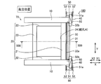
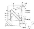
- FIG. 3 is a cross-sectional view taken along line 500-500 in FIG. It is the side view which showed the vertical hole obstruction
- FIG. 12 is a cross-sectional view taken along line 510-510 in FIG. It is the top view which showed the vertical hole obstruction
- FIG. 15 is a sectional view taken along line 520-520 in FIG.
- the vertical hole closing device 100 (Configuration of vertical hole closing device)
- the vertical hole closing device 100 is provided in the lower part where underground structures such as underground streets and subway tunnels are provided via the vertical holes H when inundation due to heavy rain or tsunami occurs. It has a function to prevent water from flowing into the space (underground space).
- the vertical hole closing device 100 is provided in an upper part of a vertical hole H extending in the vertical direction (Z direction).
- the vertical hole H extends in the vertical direction so as to connect the space below the vertical hole H and the ground located above the vertical hole H.
- the vertical hole H is, for example, a vertical hole for ventilation of an underground structure, and air in the underground structure is discharged to the ground via the vertical hole H, and air on the ground is converted into the underground structure. It is captured.
- Water is an example of the “liquid” in the claims.
- the vertical hole H is formed in a rectangular shape in plan view.
- the vertical hole H has a length of, for example, 1 m to 3 m in both the X direction and the Y direction, which are horizontal directions perpendicular to the vertical direction.
- the direction in which the pair of fixed walls 10 extends is defined as the X direction
- the direction in which the pair of fixed walls 10 face each other is defined as the Y direction.
- the vertical hole closing device 100 is installed on the ground surface S. As shown in FIG. 2, the vertical hole closing device 100 includes a pair of fixed walls 10, a frame portion 20, a movable wall 30, a pair of drums (pulleys) 40, and a pair of urging portions 50. And a pair of cables 60. Further, the vertical hole closing device 100 has a substantially symmetric structure in plan view with respect to a center line (500-500 line in FIG. 2) passing through the approximate center in the Y direction and extending in the X direction.
- a center line 500-500 line in FIG. 2
- the pair of fixed walls 10 are both formed in a rectangular shape that is long in the X direction in plan view. Further, as shown in FIG. 1, the pair of fixed walls 10 are both formed in a flat plate shape extending in the vertical direction while being fixed to the ground surface S.
- the frame portion 20 is formed in a rectangular frame shape so as to surround the vertical hole H in a plan view.
- the frame portion 20 is provided on the X1 side, and includes a frame portion 21 extending in the Y direction, a pair of inclined frame portions 22 respectively extending from the both ends of the frame portion 21 in the Y direction toward the X2 side, and a pair of A fixed frame portion 23 connected to the inclined frame portion 22 and extending in the Y direction is included.
- An opening 24 communicating with the vertical hole H is formed in a portion surrounded by the frame portion 21, the pair of inclined frame portions 22 and the fixed frame portion 23.
- the fixed frame portion 23 is formed in a flat plate shape extending in the vertical direction while being fixed to the ground surface S, and supports the pair of inclined frame portions 22.
- the fixed frame portion 23 is an example of the “fixed wall” and the “support wall” in the claims.
- the frame portion 21 is hardly inclined and is formed at a substantially uniform height position along the Y direction.
- the pair of inclined frame portions 22 are both obliquely upward (Z1 side) from the frame portion 21 (X1 side) on the movable wall 30 side toward the fixed frame portion 23 (X2 side) opposite to the movable wall 30. )
- the upper surface of the fixed frame portion 23 is provided so as to be inclined obliquely upward from the X1 side toward the X2 side so as to be continuous with the pair of inclined frame portions 22.
- the inclination angle ⁇ of the upper surfaces of the inclined frame portion 22 and the fixed frame portion 23 with respect to the vertical direction is about 45 degrees.
- the inclination angle ⁇ is preferably about 60 degrees or less.
- the movable wall 30 is provided adjacent to the X1 side of the frame portion 21. As shown in FIG. 2, the movable wall 30 is disposed at a position between the pair of fixed walls 10 facing in the Y direction in plan view.
- the movable wall 30 is formed in a flat plate shape extending in the Y direction in plan view.
- the movable wall 30 is rotated around a rotation shaft 31 provided in the vicinity of the lower end, so that the wall surface on the X2 side is the frame portion 20. It is comprised so that it can rotate to the lying position which contacts.
- the rotation shaft 31 is formed to extend in the Y direction, and both end portions in the Y direction are rotatably supported by the pair of fixed walls 10.
- the movable wall 30 In the lying position, the movable wall 30 is configured to close the vertical hole H by closing the opening 24 of the frame part 20.
- the inclination angle of the movable wall 30 in the vertical position with respect to the vertical direction is substantially the same as the inclination angle ⁇ of the upper surfaces of the inclined frame portion 22 and the fixed frame portion 23.
- a seal member 32 a is provided on the wall surface on the X2 side of the movable wall 30.
- the seal member 32a is formed in a portion of the wall surface on the X2 side of the movable wall 30 where the movable wall 30 abuts the frame portion 20 at the lying position (near the outer peripheral portion of the wall surface on the X2 side). .
- the sealing member 32b is formed in the side end surface which opposes a pair of fixed wall 10 of the movable wall 30, respectively. Thereby, it is suppressed that water leaks from the gap between the fixed wall 10 and the movable wall 30.
- each of the pair of fixed walls 10, the fixed frame portion 23 of the X2 side frame portion 20, and the X1 side movable wall 30 constitutes one side of the rectangular shape, thereby forming a rectangular shape.
- the standing wall part 70 which has is comprised.
- the pair of drums 40 is attached to the upper part of the pair of fixed walls 10 on the X1 side of the fixed wall 10, respectively.
- the drum 40 has a cylindrical shape and is configured to rotate around a rotation axis extending in the Y direction.
- the drum 40 has a function of causing the movable wall 30 to stand up (A1 direction) in a direction of an urging force by a weight member 51 described later of the urging unit 50 that works in the vertical direction.
- the pair of urging portions 50 are respectively provided in the vicinity of the pair of fixed walls 10 on the X1 side.
- the urging portion 50 includes a weight member 51 that is moved in the vertical direction by the cable 60, and a pair of guide wall portions 52 that guide the movement of the weight member 51.
- the weight member 51 is composed of a single weight 51a having a rectangular parallelepiped shape.
- the pair of guide wall portions 52 are formed in the vicinity of both ends in the X direction of the weight member 51 and are formed in a flat plate shape extending in the vertical direction while being fixed to the ground surface S and the fixed wall 10. Yes. Thereby, the weight member 51 is configured to move mainly in the vertical direction by being guided by the pair of guide wall portions 52.
- the weight member 51 is an example of the “biasing member” in the claims.
- the cable 60 connects the movable wall 30 and the weight member 51 of the urging portion 50. Specifically, the cable 60 is connected and fixed to the upper surface of the weight member 51 as shown in FIG.
- the cable 60 extends from the upper surface of the weight member 51 in the vertical direction and is hung on the drum 40. As shown in FIG. 3, the cable 60 hung on the drum 40 is connected and fixed in the vicinity of the upper end portion of the movable wall 30 opposite to the side on which the rotation shaft 31 is provided. Thereby, the cable 60 is connected to the movable wall 30 so that the urging force of the weight member 51 is applied in the standing direction (A1 direction) of the movable wall 30.
- the rotational moment M1 in the standing direction of the movable wall 30 by the urging force of the weight member 51 is configured to be substantially constant.
- the magnitude of the rotational moment M1 in the standing direction of the movable wall 30 due to the urging force of the weight member 51 is the magnitude of the rotational moment M2 (M2max) in the lying down direction (A2 direction) due to the weight of the movable wall 30 at the lying position. It is comprised so that it may become larger than this. That is, the combined moment M of the rotational moment M1 and the rotational moment M2 is configured to always be a rotational moment in the standing direction.
- the water pressure due to the flooding is applied from the X1 side of the movable wall 30, and the magnitude of the rotational moment M3 in the falling direction (A2 direction) of the movable wall 30 due to the water pressure is
- the movable wall 30 is rotated in the inclining direction against the urging force of the weight member 51 by water pressure, and the movable wall 30 is inclined. Pivoted into position.
- the opening part 24 of the frame part 20 is obstruct
- the rotational moment M2 (M2max) in the lying direction due to the weight of the movable wall 30 at the lying position is due to the biasing force of the weight member 51. Since the rotational moment M1 in the standing direction of the movable wall 30 is smaller (M2max ⁇ M1), the movable wall 30 is pivoted in the standing direction by the urging force of the weight member 51, and the movable wall 30 is pivoted to the standing position. The Thereby, the opening part 24 of the frame part 20 is open
- the movable member is movable at the upper part of the vertical hole H in which a space is formed in the lower part, and can be rotated between a lying position for closing the vertical hole H and an upright position for opening the vertical hole H.
- the wall 30 is provided, and the movable wall 30 is configured to be turned to the lying position against the urging force of the weight member 51 by water pressure by water to close the vertical hole H.
- the movable wall 30 can be rotated to the lying down position to automatically close the vertical hole H. It is possible to suppress water from flowing into the lower space via the.
- the movable wall 30 is configured such that when the water pressure decreases or disappears, the movable wall 30 is rotated to the upright position by the urging force of the weight member 51 and returned to the upright position to open the vertical hole H.
- the vertical hole H can be automatically opened by rotating the movable wall 30 to the upright position.
- the air flow between the ground and the lower space can be automatically restarted.
- the open / close state of the vertical hole H can be switched without requiring an artificial operation according to the water pressure.
- the movable wall 30 is arranged so as to form one side of the rectangular standing wall portion 70 in plan view. Thereby, when the water pressure is applied to the movable wall 30 from the horizontal direction (X1 direction) perpendicular to the surface of the movable wall 30 constituting at least one side of the rectangular shape, the water pressure applied to the movable wall 30 is reduced. Since it can be reliably enlarged, the movable wall 30 can be easily rotated to the lying down position.
- the movable wall 30 is a frame including a pair of inclined frame portions 22 and a fixed frame portion 23 that are provided in an inclined position so as to be inclined obliquely upward toward the opposite side of the movable wall 30.
- the vertical hole H is configured to be closed by closing the opening 24 of the portion 20.
- the fixed frame portion 23 that supports the pair of inclined frame portions 22 constitutes the fixed wall of the standing wall portion 70. Therefore, since it can suppress reliably that the frame part 20 moves by the fixed frame part 23, the movable wall 30 can block
- the vertical hole H can be automatically closed and opened with a simple configuration using the movable wall 30 and the pair of urging portions 50, the configuration is complicated. As compared with the above, the occurrence of failure and malfunction can be effectively suppressed. Moreover, since the number of parts which comprise the vertical hole obstruction
- a vertical hole closing device 200 according to a second embodiment of the present invention will be described with reference to FIGS.
- the weight member 51 is composed of one weight 51a
- an example in which the weight member 151 is composed of a plurality of (three) weights 151a, 151b, and 151c will be described.
- the weight member 151 is an example of the “biasing member” in the claims.
- the vertical hole closing device 200 includes an urging portion 150 instead of the urging portion 50 of the vertical hole closing device 100 in the first embodiment.
- the urging portion 150 includes a weight member 151 that can be moved in the vertical direction by the cable 60, and a guide wall portion 152 that guides the movement of the weight member 151.
- the weight member 151 is divided into three rectangular parallelepiped weights 151a, 151b, and 151c.
- the weight of the weight 151a is larger than the weight of the weight 151b
- the weight of the weight 151b is larger than the weight of the weight 151c.
- the length of the weight 151a in the X direction (the direction in which the fixed wall 10 extends) is smaller than the length of the weight 151b in the X direction
- the length of the weight 151b in the X direction is longer than the length of the weight 151c in the X direction. It is formed to be smaller.
- a cable 60 is connected and fixed to the upper surface of the weight 151a.
- the weight 151a is disposed on the ground surface S. Further, through holes 151d and 151e extending in the vertical direction are formed in the weights 151b and 151c, respectively, and the cable 60 passes through the inside.
- the guide wall part 152 has a pair of guide walls 152a, a pair of guide walls 152b, and a pair of guide walls 152c.
- the pair of guide walls 152a is formed in the vicinity of both ends in the X direction of the weight 151a, and has a function of guiding the weight 151a.
- the pair of guide walls 152a are formed in a flat plate shape extending in the vertical direction while being fixed to the ground surface S and the fixed wall 10.
- the inclination angle ⁇ of the movable wall 30 with respect to the vertical direction becomes about 15 degrees (position Pb, see FIG. 8)
- the height H1 in the vertical direction from the ground surface S is set so as to be substantially the same height position as the upper end surface of.
- a weight 151b is arranged on the upper surface of the guide wall 152a.
- the pair of guide walls 152b are formed in the vicinity of both ends in the X direction of the weight 151b, and have a function of guiding the weight 151b.
- the pair of guide walls 152b are formed in a flat plate shape extending in the vertical direction while being fixed to the fixed wall 10.
- the upper surface of the weight 151b in the weight member 151 lifted by the cable 60 is about 30 degrees (position Pc, see FIG. 8)
- the height H2 in the vertical direction from the ground surface S is set so as to be substantially the same height position as the upper end surface of the guide wall 152b.
- the lower end surface of the guide wall 152b is provided at substantially the same height as the upper end surface of the guide wall 152a.
- a weight 151c is arranged on the upper surface of the guide wall 152b.
- the pair of guide walls 152c are formed in the vicinity of both ends in the X direction of the weight 151c, and have a function of guiding the weight 151c.
- the pair of guide walls 152c are formed in a flat plate shape extending in the vertical direction while being fixed to the fixed wall 10.
- the height H3 in the vertical direction from the ground surface S is set so as to be substantially the same height position as the upper end surface of the guide wall 152c.
- the lower end surface of the guide wall 152c is provided at substantially the same height as the upper end surface of the guide wall 152b.
- the combined moment M of the rotational moment M1 and the rotational moment M2 is configured to always be a rotational moment in the standing direction.
- the movable wall 30 In the normal state of the vertical hole closing device 200, as shown in FIGS. 7 and 8, the movable wall 30 is erected by the urging force of the weight 151a of the weight member 151 via the cable 60 (A1). Direction) is applied. Thereby, the movable wall 30 is configured to be automatically positioned at the standing position Pa in the normal state. Then, the water pressure due to the flooding is applied from the X1 side of the movable wall 30, and the magnitude of the rotational moment M3 in the lying down direction (A2 direction) of the movable wall 30 due to the water pressure is rotated in the standing direction by the urging force of the weight 151a.
- the rotational moment in the standing direction is the rotational moment M1a in the standing direction due to the urging force of one of the three weights 151a
- the movable wall 30 is allowed to fall down even if the water pressure is relatively low. Can be rotated.
- the rotational moment M2 in the lying down direction (A2 direction) due to the weight of the movable wall 30 changes greatly on the side closer to the standing position, and therefore, of the three weights 151a, 151b and 151c,
- By maximizing the weight it is possible to apply an urging force to the movable wall 30 in accordance with the change of the rotational moment M2 in the lying down direction due to the weight of the movable wall 30.
- the combined moment M in the second embodiment is ideal on the side closer to the lodging position. It approaches a composite moment (a substantially constant rotational moment regardless of the tilt angle ⁇ ). That is, in the vertical hole closing device, it is possible to approach an ideal composite moment by dividing the weight into a plurality of weights. It should be noted that the resultant moment can be made closer to the ideal resultant moment by dividing the weight more than three.
- the other structure of 2nd Embodiment is the same as that of the said 1st Embodiment.
- the movable member is movable to the upper position of the vertical hole H in which a space is formed in the lower portion, and can be rotated between a lying position where the vertical hole H is closed and a standing position where the vertical hole H is opened.
- a wall 30 is provided, and the movable wall 30 is configured to be closed to the vertical hole H by being rotated to a lying position against the urging force of the weight member 151 by water pressure by water. Thereby, it can suppress that water flows into the space of the lower part through the vertical hole H similarly to the said 1st Embodiment.
- the movable wall 30 is configured to be rotated to the standing position by the urging force of the weight member 151 and return to the standing position to open the vertical hole H when the water pressure decreases or disappears.
- the vertical holes are formed so that the urging force by the weight member 151 gradually decreases as the number of weights contributing to the urging force decreases as the movable wall 30 moves from the lying position to the standing position.
- the occlusion device 200 is configured. Thereby, when the water pressure increases slightly, the movable wall 30 can be rotated in the lying down direction at an early stage, so that the water can be prevented from flowing into the lower space through the vertical hole H at an early stage.
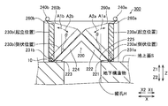
- a vertical hole closing device 300 according to a third embodiment of the present invention will be described with reference to FIGS. 5, 11, and 12.
- a pair of movable walls 230a and 230b facing each other will be described.
- the vertical hole closing device 300 includes a pair of fixed walls 10, a frame portion 220, a pair of movable walls 230a and 230b, a pair of drums 240a, and a pair of pairs.
- the drum 240b includes a pair of urging portions 250a and a pair of urging portions 250b, a pair of cables 260a and a pair of cables 260b.
- the frame part 220 is formed in a rectangular frame shape so as to surround the vertical hole H in plan view. Further, the frame part 220 is provided on the X1 side, and extends from the Y part in the frame part 221 extending in the Y direction to the center part in the X direction of the frame part 220 toward the X2 side. A pair of inclined frame portions 222 that extend, a frame portion 223 that is provided on the X2 side and extends in the Y direction, and both ends in the Y direction of the frame portion 223 from the center portion in the X direction of the frame portion 220 toward the X1 side. And a pair of inclined frame portions 224 extending respectively. An opening 225 communicating with the vertical hole H is formed in a portion surrounded by the frame portions 221 and 223, the pair of inclined frame portions 222, and the pair of inclined frame portions 224.
- the frame portions 221 and 223 are hardly inclined and are formed at substantially uniform height positions along the Y direction.
- the pair of inclined frame portions 222 are inclined obliquely upward (Z1 side) from the frame portion 221 (X1 side) on the movable wall 230a side toward the center portion (X2 side) in the X direction of the frame portion 220. It is provided to do.
- the pair of inclined frame portions 224 are provided so as to be inclined obliquely upward from the frame portion 223 on the movable wall 230b side (X2 side) toward the center portion (X1 side) in the X direction of the frame portion 220. It has been.
- the inclination angle ⁇ of the inclined frame portions 222 and 224 with respect to the vertical direction is about 45 degrees.
- the inclination angle ⁇ is preferably about 60 degrees or less.
- the movable walls 230 a and 230 b are arranged so as to constitute two opposing sides of the rectangular standing wall portion 270.
- the movable wall 230a is provided adjacent to the X1 side of the frame portion 221. As shown in FIG. 12, the movable wall 230a rotates around a rotation shaft 231a provided in the vicinity of the lower end thereof, so that the wall surface on the X2 side and the standing position where the wall surface extends in the vertical direction It is comprised so that it can rotate to the lying position which touches. And in the state rotated to the fall position, the wall surface on the X2 side of the movable wall 230a abuts on substantially the whole surface of the pair of inclined frame portions 222 of the frame portion 220, and the X1 side of the opening portion 225 of the frame portion 220 is contacted. It is configured to close.
- the movable wall 230b is provided adjacent to the X2 side of the frame portion 223.
- the movable wall 230b rotates around a rotation shaft 231b provided in the vicinity of the lower end, thereby rotating to an upright position where the wall surface extends in the vertical direction and a lying position where the X1 wall surface contacts the frame portion 220. It is configured as possible.
- the wall surface on the X1 side of the movable wall 230b is in contact with substantially the entire surface of the pair of inclined frame portions 224 of the frame portion 220 and closes the X2 side of the opening portion 225 of the frame portion 220 in the lying position.
- the vertical hole H is completely closed by closing the opening 225 of the frame 220 by the movable walls 230a and 230b.
- the pair of drums 240a is attached to the upper part of the pair of fixed walls 10 on the X1 side of the fixed wall 10, respectively.
- the pair of drums 240b are attached to the upper portions of the pair of fixed walls 10 on the X2 side of the fixed wall 10, respectively.
- the pair of urging portions 250 a are provided in the vicinity of the pair of fixed walls 10 on the X1 side.
- the pair of urging portions 250b are provided in the vicinity of the pair of fixed walls 10 on the X2 side.
- the pair of cables 260a connects the movable wall 230a and the weight member 51 of the urging portion 250a on the X1 side.
- the pair of cables 260b connects the movable wall 230b and the weight member 51 of the urging portion 250b on the X2 side.
- the longitudinal hole closing device 300 not only has a substantially symmetric structure with respect to the center line extending in the X direction in plan view, but also passes through the approximate center in the X direction. It is formed so as to have a substantially symmetrical structure with respect to the center line extending in the Y direction.
- the combined moment M with the rotational moment M2 (M2max) in the lying down direction (A2a direction) due to the weight of 230a is configured to always be a rotational moment in the standing direction, as in the first embodiment.
- the combined moment M with the moment M2 (M2max) is configured to always be a rotational moment in the standing direction.
- the water pressure due to the flooding is applied from the X1 side of the movable wall 230a, and the magnitude of the rotational moment M2 in the falling direction (A2a direction) of the movable wall 230a due to the water pressure is the rising direction of the movable wall 230a by the weight member 51 ( When the magnitude of the rotational moment M1 in the A1a direction) is exceeded, the movable wall 230a is rotated to the lying down position.
- the water pressure is applied from the X2 side of the movable wall 230b, and the magnitude of the rotational moment M2 in the falling direction (A2b direction) of the movable wall 230b due to the water pressure is determined by the rising direction (A1b) of the movable wall 230b by the weight member 51.
- the movable wall 230b is rotated to the lying position. Thereby, the opening part 225 of the frame part 220 is obstruct
- the movable wall 230a stands up due to the rotational moment M1 in the standing direction (A1a direction) of the movable wall 230a by the urging force of the weight member 51. Pivoted into position.
- the movable wall 230b is caused by the rotational moment M1 in the rising direction (A1b direction) of the movable wall 230b by the urging force of the weight member 51. It is turned to the standing position.
- the opening part 225 of the frame part 220 is open
- the remaining configuration of the third embodiment is similar to that of the aforementioned first embodiment.
- the movable member is movable to the upper position of the vertical hole H in which a space is formed in the lower portion, and can be rotated between a lying position for closing the vertical hole H and a standing position for opening the vertical hole H.
- Walls 230a and 230b are provided, and the movable walls 230a and 230b are configured to be turned to the lying down position against the urging force of the weight member 51 by water pressure from water to close the vertical hole H. Thereby, it can suppress that water flows into the space of the lower part through the vertical hole H similarly to the said 1st Embodiment.
- the movable walls 230a and 230b are configured to be rotated to the upright position by the urging force of the weight member 51 and returned to the upright position to open the vertical hole H when the water pressure decreases or disappears.
- the movable walls 230a and 230b are arranged so as to constitute two opposing sides of the rectangular standing wall portion 270.
- occlude the vertical hole H can be made small.
- the vertical hole closing device 300 can be reduced in size.
- the vertical hole H can be reliably obstruct
- the remaining effects of the third embodiment are similar to those of the aforementioned first embodiment.
- a vertical hole closing device 400 according to a fourth embodiment of the present invention will be described with reference to FIGS. 5, 13, and 14.
- the vertical hole closing device 400 of the fourth embodiment an example in which a part of the configuration of the vertical hole closing device 300 of the third embodiment is arranged in the vertical hole H will be described.
- symbol as 3rd Embodiment is attached
- the vertical hole closing device 400 includes a pair of fixed walls 10, a frame portion 320, a pair of movable walls 330a and 330b, a pair of drums 240a, and a pair of
- the drum 240b includes a pair of auxiliary drums 341a and a pair of auxiliary drums 341b, a pair of urging portions 250a and a pair of urging portions 250b, a pair of cables 360a and a pair of cables 360b.
- the frame part 320 is fixed to the inner peripheral surface of the vertical hole H at the upper part (upper part) inside the vertical hole H. Moreover, the frame part 320 is formed in the rectangular frame shape according to the shape of the rectangular-shaped vertical hole H by planar view. Further, the frame portion 320 is provided on the X1 side in a plan view, and extends from the Y direction to the frame portion 321 extending from the Y direction to the center portion of the frame portion 320 in the X direction from the X2 side.
- a pair of inclined frame portions 322 extending toward the X2 side, a frame portion 323 provided on the X2 side, extending in the Y direction, and both ends of the frame portion 323 in the Y direction to a center portion in the X direction of the frame portion 320 X1
- a pair of inclined frame portions 324 each extending toward the side.
- An opening 325 is formed in a portion surrounded by the frame portions 321 and 323, the pair of inclined frame portions 322, and the pair of inclined frame portions 324.
- both the upper surface of the frame portion 321 and the pair of inclined frame portions 322 are inclined obliquely upward from the X1 side toward the center portion (X2 side) of the frame portion 320 in the X direction.
- both the upper surface of the frame portion 323 and the pair of inclined frame portions 324 are provided so as to be inclined obliquely upward from the X2 side toward the center portion (X1 side) of the frame portion 320 in the X direction.
- the inclination angle ⁇ with respect to the vertical direction of the upper surface of the frame portion 321, the upper surface of the inclined frame portion 322, the upper surface of the frame portion 323, and the inclined frame portion 324 is about 45 degrees.
- the inclination angle ⁇ is preferably about 60 degrees or less.
- drainage holes Ca and Cb that pass through the underground structure and are connected to the ground are provided near the upper surfaces of the frame portions 321 and 323, respectively.
- the drain holes Ca and Cb are provided for discharging the water accumulated on the inclined upper surfaces of the frame portions 321 and 323 to the ground using a drainage facility (not shown).
- the movable wall 330a is provided adjacent to the upper part (upper part) inside the vertical hole H and above the frame part 321 on the X1 side.
- the movable wall 330a rotates around a rotation shaft 331a provided in the vicinity of the lower end, so that the wall surface stands up along the vertical direction in which the vertical hole H extends and the wall surface on the X2 side is in contact with the frame portion 320. It is configured to be rotatable to a position.
- the wall surface on the X2 side of the movable wall 330a contacts substantially the entire surface of the pair of inclined frame portions 322 of the frame portion 320, and the X1 side of the opening portion 325 of the frame portion 320 It is configured to close.
- the movable wall 330b is provided adjacent to the upper part (upper part) inside the vertical hole H and above the frame part 323 on the X2 side.
- the movable wall 330b rotates around a rotation shaft 331b provided in the vicinity of the lower end, so that the wall surface stands up along the vertical direction in which the vertical hole H extends, and the wall surface on the X1 side is in contact with the frame portion 320. It is configured to be rotatable to a position.
- the wall surface on the X1 side of the movable wall 330b is in contact with substantially the entire surface of the pair of inclined frame portions 324 of the frame portion 320, and the X2 side of the opening portion 325 of the frame portion 320 is moved. It is configured to close. As a result, the vertical hole H is completely closed by closing the opening 325 of the frame 320 by both the movable walls 330a and 330b.
- the upper end surfaces of the movable walls 330a and 330b are configured to be located above the ground surface S (Z1 side).
- the water pressure is applied to the movable walls 330a and 330b when the water at the time of flooding contacts the wall surfaces of the movable walls 330a and 330b exposed to the ground.
- the pair of auxiliary drums 341a are respectively disposed below the pair of drums 240a (Z2 side) on the X1 side.
- a pair of cables 360a are hung on the pair of auxiliary drums 341a, respectively.
- the pair of auxiliary drums 341b are respectively disposed below the pair of drums 240b on the X2 side.
- a pair of cables 360b are hung on the pair of auxiliary drums 341b, respectively.
- the pair of cables 360a connects the movable wall 330a and the weight member 51 of the urging portion 250a via the pair of drums 240a and the pair of auxiliary drums 341a on the X1 side, respectively.
- the pair of cables 360b connect the movable wall 330b and the weight member 51 of the biasing portion 250b via the pair of drums 240b and the pair of auxiliary drums 341b, respectively, on the X2 side.
- the vertical hole closing device 400 not only has a substantially symmetrical structure with respect to the center line extending in the X direction in plan view, but also passes through the approximate center in the X direction. It is formed so as to have a substantially symmetrical structure with respect to the center line extending in the Y direction.
- the combined moment M with the rotational moment M2 (M2max) in the lying down direction (A2a direction) due to the weight of 330a is configured so as to always be a rotational moment in the standing direction, as in the first and third embodiments. Has been.
- the combined moment M with the moment M2 (M2max) is configured to always be a rotational moment in the standing direction.
- the other structure of 4th Embodiment and the rotation operation of movable wall 330a and 330b are the same as that of the said 3rd Embodiment.
- the movable walls 330a and 330b are provided, and the movable walls 330a and 330b are configured to be pivoted to the lying down position against the urging force of the weight member 51 by water pressure by water to close the vertical hole H. Thereby, it can suppress that water flows into the space of the lower part through the vertical hole H similarly to the said 3rd Embodiment.
- the movable walls 330a and 330b are configured to be rotated to the upright position by the urging force of the weight member 51 and returned to the upright position to open the vertical hole H when the water pressure decreases or disappears.
- positions the frame part 320 and the movable walls 330a and 330b on the ground is ensured by arrange
- the remaining effects of the fourth embodiment are similar to those of the aforementioned third embodiment.
- the vertical hole closing device 100 (200, 300, 400) of the present invention is connected to the vertical hole H that connects the space of an underground structure such as an underground mall and a subway tunnel and the ground.
- an applied example has been shown, the present invention is not limited to this.
- the vertical hole closing device of the present invention is not limited to the case where it is applied to a vertical hole that connects an underground space and the ground, but connects a lower floor and an upper floor (including a rooftop) in a structure provided on the ground.
- the vertical hole closing device of the present invention may be applied to the vertical hole. Thereby, when water leakage etc. generate
- the vertical hole H extends in the vertical direction.
- the vertical hole may be formed so as to extend while being inclined in the vertical direction.
- a part of the vertical hole may have a portion extending in a direction orthogonal to the vertical direction.
- the “liquid” in the claims is “water”, but the present invention is not limited to this.
- the “liquid” in the claims is not limited to water as long as it is liquid, and may be, for example, oil and liquid medicine.
- the weight member 51 (151) is used as the “biasing member” in the claims, but the present invention is not limited to this.
- a spring may be used as the biasing member.
- the biasing force can be changed linearly by using a spring as the biasing member.
- a plurality of types of springs having different spring constants may be used.
- the weight member and the spring are preferably combined so as to approach an ideal combined moment (a substantially constant rotational moment regardless of the inclination angle) as shown in FIG.
- the weight of the weight 151a is larger than the weight of the weight 151b
- the weight of the weight 151b is larger than the weight of the weight 151c.
- the present invention is not limited to this. In the present invention, for example, the weights of the plurality of weights may be substantially the same.
- the vertical hole H has a rectangular shape in plan view, but the present invention is not limited to this.
- the planar shape of the vertical hole is not particularly limited.
- the vertical hole may have a circular shape, an elliptical shape, a polygonal shape, or the like in plan view.
- the movable wall 30 (230a, 230b, 330a, 330b) is a flat plate is shown, but the present invention is not limited to this.
- the shape of the movable wall is not particularly limited as long as the movable wall can block the vertical hole.
- the present invention is not limited to this.
- the frame portion may not be provided.
- the movable wall is configured to be larger than the opening shape of the vertical hole so that the movable wall directly closes the vertical hole.
- the frame portion 20 (220, 320) has an inclined portion
- the present invention is not limited to this.
- the frame portion may be arranged in a horizontal plane without being inclined.
- the drum 40 (240a, 240b) is used to set the direction of the urging force of the weight member 51 acting in the vertical direction to the movable wall 30 in the standing direction (A1 direction).
- the present invention is not limited to this.
- the direction of the urging force of the weight member acting in the vertical direction may be set to the upright direction of the movable wall.
- a pair of urging portions 50 (150, 250a, 250b) is provided for one movable wall 30 (230a, 230b, 330a, 330b) is shown.
- the present invention is not limited to this.
- one urging portion (biasing member) is provided for one movable wall. Also good.
- FIGS. 2, 11 and 13 only the urging portion on one side in the Y direction may be left and the urging portion on the other side may be deleted.
Landscapes
- Engineering & Computer Science (AREA)
- Architecture (AREA)
- Chemical & Material Sciences (AREA)
- Combustion & Propulsion (AREA)
- Mechanical Engineering (AREA)
- General Engineering & Computer Science (AREA)
- Business, Economics & Management (AREA)
- Emergency Management (AREA)
- Environmental & Geological Engineering (AREA)
- Civil Engineering (AREA)
- Structural Engineering (AREA)
- Buildings Adapted To Withstand Abnormal External Influences (AREA)
Abstract
この縦孔閉塞装置(100)は、下部に空間が形成されている縦孔(H)の上部に設けられた可動壁(30)と、付勢部材(51)と、を備える。可動壁は、液体による液体圧により付勢部材の付勢力に抗して倒伏位置に回動されて縦孔を閉塞するとともに、液体圧が減少または消失した場合に、付勢部材の付勢力により起立位置に回動されて、起立位置に復帰して縦孔を開放するように構成されている。
Description
本発明は、縦孔閉塞装置に関する。
従来、下部に空間(地下空間)が形成された構造が知られている。このような下部に空間(地下空間)が形成された構造は、たとえば、特許第2765630号に開示されている。
特許第2765630号には、地下鉄の駅構造としての地下空間の構造が開示されている。この地下空間の構造には、下部の地下空間内(駅ホームなど)と上部の地上とを接続する排気口、吸気口および階段が設けられている。
しかしながら、特許第2765630号に開示された地下空間の構造では、集中豪雨または津波による浸水が発生した場合などにおいて、水面が、排気口、吸気口および階段などの地上における開口(縦孔)よりも上方に位置した際には、縦孔を介して、水が下部の地下空間内に流れ込んでしまうという問題点があると考えられる。この場合、水を下部の空間から上部に排出するのは容易ではないため、水が下部の空間に流れ込むのを抑制するという要望は極めて大きい。
この発明は、上記のような課題を解決するためになされたものであり、この発明の1つの目的は、縦孔を介して液体が下部の空間に流れ込むのを抑制することが可能な縦孔閉塞装置を提供することである。
上記目的を達成するために、この発明の一の局面における縦孔閉塞装置は、下部に空間が形成されている縦孔の上部に設けられ、縦孔を閉塞する倒伏位置と縦孔を開放する起立位置とに回動可能な可動壁と、可動壁を起立位置に位置するように付勢する付勢部材と、を備え、可動壁は、液体による液体圧により付勢部材の付勢力に抗して倒伏位置に回動されて縦孔を閉塞するとともに、液体圧が減少または消失した場合に、付勢部材の付勢力により起立位置に回動されて、起立位置に復帰して縦孔を開放するように構成されている。なお、「縦孔の上部」は、縦孔の上方に位置する外部だけでなく、縦孔の内部における上部(上側部分)も含んでいる。また、液体圧には、液体による静圧と、液体による動圧との両方が含まれる。
この発明の一の局面による縦孔閉塞装置では、上記のように、下部に空間が形成されている縦孔の上部に、縦孔を閉塞する倒伏位置と縦孔を開放する起立位置とに回動可能な可動壁を設け、可動壁を、液体による液体圧により付勢部材の付勢力に抗して倒伏位置に回動されて縦孔を閉塞するように構成する。これにより、たとえば浸水などに起因して、液体による液体圧が可動壁に加えられた際に、可動壁を倒伏位置に回動させて縦孔を自動的に閉塞することができるので、縦孔を介して液体が下部の空間(地下構造物などが設けられた空間)に流れ込むのを抑制することができる。また、可動壁を、液体圧が減少または消失した場合に、付勢部材の付勢力により起立位置に回動されて、起立位置に復帰して縦孔を開放するように構成する。これにより、浸水などに起因する液体圧が減少または消失した際には、可動壁を起立位置に回動させて縦孔を自動的に開放することができるので、縦孔を介して、上部の空間と下部の空間との間における空気の流通などを自動的に再開させることができる。この結果、液体圧の状況に応じて、人為的な操作を要すことなく縦孔の開閉状態を切り替えることができる。
上記一の局面による縦孔閉塞装置において、好ましくは、縦孔の上部に設けられ、平面視で、矩形形状を有する立壁部をさらに備え、可動壁は、平面視で、矩形形状の立壁部の少なくとも1辺を構成するように配置されている。このように構成すれば、矩形形状の少なくとも1辺を構成する可動壁の壁面に対して垂直な水平方向から、液体による液体圧が加えられた際に、可動壁に加えられる液体圧を確実に大きくすることができるので、可動壁を倒伏位置に容易に回動させることができる。
上記一の局面による縦孔閉塞装置において、好ましくは、縦孔の上部において、可動壁側から可動壁とは反対側に向かって斜め上方に傾斜して設けられ、縦孔に対応する開口部を有する枠部をさらに備え、可動壁は、倒伏位置において枠部の開口部を閉塞することによって縦孔を閉塞するように構成されている。ここで、枠部が水平である場合には、倒伏位置に回動された際に、可動壁の壁面が水平に延びることになる。この際、液体圧だけでなく、可動壁自体の自重の略全てが可動壁を倒伏方向に回動させる力となり、この結果、可動壁を起立位置に復帰させるのに必要な力が大きくなってしまう。これにより、上記本発明の構成のように、枠部を、可動壁側から可動壁とは反対側に向かって斜め上方に傾斜するように構成すれば、枠部が水平である場合と比べて、可動壁を起立位置に復帰させるのに必要な力が大きくなるのを抑制することができるので、付勢部材の付勢力を大きくするために付勢部材を大型化する必要がない。これにより、縦孔閉塞装置の大型化を抑制することができる。
この場合、好ましくは、枠部を傾斜した状態で支持する支持壁をさらに備え、支持壁は、縦孔の上部に設けられた立壁部の固定壁を構成するように配置されている。このように構成すれば、固定壁を構成する支持壁により、枠部が移動するのを確実に抑制することができるので、枠部が移動することに起因して可動壁が枠部の開口部を閉塞できなくなるのを確実に抑制することができる。
上記一の局面による縦孔閉塞装置において、好ましくは、付勢部材は、錘部材を含み、錘部材は、複数の錘を含むとともに、可動壁が倒伏位置から起立位置に向かうにしたがって、複数の錘のうちの付勢力に寄与する錘の個数が減少することによって、付勢力が徐々に弱くなるように構成されている。このように構成すれば、液体圧が若干増加した際に早期に可動壁を倒伏方向に回動させることができるので、縦孔を介して液体が下部の空間に流れ込むのを早期に抑制することができる。
上記可動壁が立壁部の少なくとも1辺を構成する構成において、好ましくは、可動壁は、平面視で、矩形形状の立壁部の対向する2辺を構成するように配置されている。このように構成すれば、対向する2辺を構成する可動壁により、1辺のみを可動壁により構成した場合と比べて、縦孔を閉塞させる可動壁の大きさを小さくすることができる。これにより、縦孔閉塞装置の小型化を図ることができる。また、開口面積の大きな縦孔であっても、2辺を構成する2個の可動壁により、縦孔を確実に閉塞させることができる。
本発明によれば、上記のように、縦孔を介して液体が下部の空間に流れ込むのを抑制することができる。
以下、本発明の実施形態を図面に基づいて説明する。
[第1実施形態]
図1~図6を参照して、本発明の第1実施形態による縦孔閉塞装置100について説明する。
図1~図6を参照して、本発明の第1実施形態による縦孔閉塞装置100について説明する。
(縦孔閉塞装置の構成)
本発明の第1実施形態による縦孔閉塞装置100は、集中豪雨または津波による浸水が発生した場合に、縦孔Hを介して、地下街および地下鉄のトンネルなどの地下構造物が設けられた下部の空間(地下空間)に、水が流れ込むのを抑制する機能を有している。縦孔閉塞装置100は、図1に示すように、鉛直方向(Z方向)に延びる縦孔Hの上部に設けられている。この縦孔Hは、縦孔Hの下部の空間と、縦孔Hの上部に位置する地上とを接続するように鉛直方向に延びている。なお、縦孔Hは、たとえば、地下構造物の換気用の縦孔であり、縦孔Hを介して、地下構造物内の空気が地上に排出されるとともに、地上の空気が地下構造物に取り込まれる。また、水は、特許請求の範囲の「液体」の一例である。
本発明の第1実施形態による縦孔閉塞装置100は、集中豪雨または津波による浸水が発生した場合に、縦孔Hを介して、地下街および地下鉄のトンネルなどの地下構造物が設けられた下部の空間(地下空間)に、水が流れ込むのを抑制する機能を有している。縦孔閉塞装置100は、図1に示すように、鉛直方向(Z方向)に延びる縦孔Hの上部に設けられている。この縦孔Hは、縦孔Hの下部の空間と、縦孔Hの上部に位置する地上とを接続するように鉛直方向に延びている。なお、縦孔Hは、たとえば、地下構造物の換気用の縦孔であり、縦孔Hを介して、地下構造物内の空気が地上に排出されるとともに、地上の空気が地下構造物に取り込まれる。また、水は、特許請求の範囲の「液体」の一例である。
また、縦孔Hは、平面視で、矩形形状に形成されている。なお、縦孔Hは、鉛直方向に対して垂直な水平方向であるX方向およびY方向に、共に、たとえば、1m~3mの長さを有している。なお、平面視で、一対の固定壁10が延びる方向をX方向とし、一対の固定壁10が対向する方向をY方向とする。
縦孔閉塞装置100は、地上面Sに設置されている。縦孔閉塞装置100は、図2に示すように、互いに対向する一対の固定壁10と、枠部20と、可動壁30と、一対のドラム(滑車)40と、一対の付勢部50と、一対のケーブル60とを備えている。また、縦孔閉塞装置100は、平面視で、Y方向の略中央を通り、X方向に延びる中心線(図2の500―500線)に対して略対称な構造を有している。
一対の固定壁10は、共に、平面視で、X方向に長い矩形状に形成されている。また、図1に示すように、一対の固定壁10は、共に、地上面Sに固定された状態で、鉛直方向に延びる平板状に形成されている。
枠部20は、図2に示すように、平面視で、縦孔Hを取り囲むように、矩形枠状に形成されている。また、枠部20は、X1側に設けられ、Y方向に延びる枠部分21と、枠部分21のY方向の両端部から、X2側に向かってそれぞれ延びる一対の傾斜枠部分22と、一対の傾斜枠部分22に接続され、Y方向に延びる固定枠部分23とを含んでいる。そして、枠部分21、一対の傾斜枠部分22および固定枠部分23によって囲まれた部分に、縦孔Hに連通する開口部24が形成されている。なお、固定枠部分23は、地上面Sに固定された状態で、鉛直方向に延びる平板状に形成されており、一対の傾斜枠部分22を支持している。なお、固定枠部分23は、特許請求の範囲の「固定壁」および「支持壁」の一例である。
図3に示すように、枠部分21は、ほとんど傾斜しておらず、Y方向に沿って略一様の高さ位置に形成されている。一方、一対の傾斜枠部分22は、共に、可動壁30側の枠部分21(X1側)から可動壁30とは反対側の固定枠部分23(X2側)に向かって、斜め上方(Z1側)に傾斜するように設けられている。また、固定枠部分23の上面は、一対の傾斜枠部分22に連続するように、X1側からX2側に向かって、斜め上方に傾斜するように設けられている。また、傾斜枠部分22および固定枠部分23の上面の、鉛直方向に対する傾斜角θは、約45度である。なお、傾斜角θは、約60度以下であるのが好ましい。
可動壁30は、枠部分21のX1側に隣接して設けられている。可動壁30は、図2に示すように、平面視で、Y方向に対向する一対の固定壁10に挟まれた位置に配置されている。また、可動壁30は、平面視で、Y方向に延びる平板状に形成されている。また、図3に示すように、可動壁30は、下端近傍に設けられた回動軸31周りに回動することによって、壁面が鉛直方向に延びる起立位置と、X2側の壁面が枠部20に当接する倒伏位置とに回動可能なように構成されている。なお、回動軸31は、図2に示すように、Y方向に延びるように形成されているとともに、Y方向の両端部がそれぞれ一対の固定壁10に回動可能に支持されている。
そして、倒伏位置において、可動壁30は、枠部20の開口部24を閉塞することによって、縦孔Hを閉塞するように構成されている。なお、倒伏位置における可動壁30の鉛直方向に対する傾斜角は、傾斜枠部分22およびよび固定枠部分23の上面の傾斜角θと略同一である。
また、可動壁30のX2側の壁面には、シール部材32aが設けられている。具体的には、シール部材32aは、可動壁30のX2側の壁面のうち、倒伏位置において可動壁30が枠部20に当接する部分(X2側の壁面における外周部近傍)に形成されている。これにより、倒伏位置において、水が枠部20と可動壁30との隙間から縦孔Hに侵入するのが抑制されている。また、図2に示すように、可動壁30の一対の固定壁10と対向する側端面には、それぞれ、シール部材32bが形成されている。これにより、水が固定壁10と可動壁30との隙間から水が漏れるのが抑制されている。
なお、平面視において、一対の固定壁10と、X2側の枠部20の固定枠部分23と、X1側の可動壁30との各々が矩形形状の1辺を構成することにより、矩形形状を有する立壁部70が構成されている。
一対のドラム40は、それぞれ、固定壁10のX1側において、一対の固定壁10の上部に取り付けられている。ドラム40は、円柱形状を有するとともに、Y方向に延びる回転軸線周りに回転するように構成されている。このドラム40は、鉛直方向に働く付勢部50の後述する錘部材51による付勢力の方向を可動壁30を起立方向(A1方向)にする機能を有している。
一対の付勢部50は、それぞれ、一対の固定壁10のX1側の近傍に設けられている。付勢部50は、図4に示すように、ケーブル60により鉛直方向に移動される錘部材51と、錘部材51の移動をガイドする一対のガイド壁部52とを含んでいる。錘部材51は、直方体状の1個の錘51aから構成されている。一対のガイド壁部52は、錘部材51のX方向の両端部近傍にそれぞれ形成されているとともに、地上面Sおよび固定壁10に固定された状態で、鉛直方向に延びる平板状に形成されている。これにより、錘部材51は、一対のガイド壁部52によりガイドされることによって、主に鉛直方向にのみ移動するように構成されている。なお、錘部材51は、特許請求の範囲の「付勢部材」の一例である。
ケーブル60は、可動壁30と、付勢部50の錘部材51とを接続している。具体的には、ケーブル60は、図4に示すように、錘部材51の上面に接続固定されている。また、ケーブル60は、錘部材51の上面から鉛直方向に延びて、ドラム40に掛けられている。そして、ドラム40に掛けられたケーブル60は、図3に示すように、可動壁30の回動軸31が設けられた側とは反対側の上端部近傍に接続固定されている。これにより、ケーブル60は、可動壁30の起立方向(A1方向)へ錘部材51の付勢力が加えられるように、可動壁30に接続されている。
ここで、第1実施形態では、図5に示すように、錘部材51の付勢力による可動壁30の起立方向への回転モーメントM1は、略一定になるように構成されている。また、錘部材51の付勢力による可動壁30の起立方向への回転モーメントM1の大きさは、倒伏位置における可動壁30の自重による倒伏方向(A2方向)への回転モーメントM2(M2max)の大きさよりも大きくなるように構成されている。つまり、回転モーメントM1と回転モーメントM2との合成モーメントMは、常に起立方向の回転モーメントになるように構成されている。
(可動壁の回動動作)
上記のように構成されていることによって、第1実施形態における縦孔閉塞装置100の通常状態においては、図3に示すように、可動壁30に、ケーブル60を介した錘部材51による付勢力により、可動壁30の起立方向(A1方向)への回転モーメントM1が加えられる。これにより、可動壁30は、通常状態において、起立位置に自動的に位置するように構成されている。
上記のように構成されていることによって、第1実施形態における縦孔閉塞装置100の通常状態においては、図3に示すように、可動壁30に、ケーブル60を介した錘部材51による付勢力により、可動壁30の起立方向(A1方向)への回転モーメントM1が加えられる。これにより、可動壁30は、通常状態において、起立位置に自動的に位置するように構成されている。
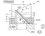
そして、図6に示すように、浸水による水圧が可動壁30のX1側から加えられて、水圧による可動壁30の倒伏方向(A2方向)への回転モーメントM3の大きさが、錘部材51の付勢力による可動壁30の起立方向への回転モーメントM1の大きさを超えると、水圧により錘部材51の付勢力に抗して可動壁30が倒伏方向に回動されて、可動壁30は倒伏位置に回動される。これにより、可動壁30により、枠部20の開口部24が閉塞されて、縦孔Hが自動的に閉塞される。
その後、可動壁30が倒伏位置の状態において、浸水による水圧が減少して、水圧による可動壁30の倒伏方向への回転モーメントM3と、倒伏位置における可動壁30の自重による倒伏方向への回転モーメントM2との合計が、錘部材51の付勢力による可動壁30の起立方向への回転モーメントM1を下回る(M2+M3<M1)と、錘部材51の付勢力により可動壁30が起立方向に回動されて、可動壁30は起立位置(図3参照)に回動される。また、可動壁30が倒伏位置の状態において、浸水による水圧が消失した際には、倒伏位置における可動壁30の自重による倒伏方向への回転モーメントM2(M2max)が、錘部材51の付勢力による可動壁30の起立方向への回転モーメントM1よりも小さい(M2max<M1)ので、錘部材51の付勢力により可動壁30が起立方向に回動されて、可動壁30は起立位置に回動される。これにより、可動壁30により、枠部20の開口部24が開放されて、縦孔Hが自動的に開放される。
(第1実施形態の効果)
第1実施形態では、以下のような効果を得ることができる。
第1実施形態では、以下のような効果を得ることができる。
第1実施形態では、上記のように、下部に空間が形成されている縦孔Hの上部に、縦孔Hを閉塞する倒伏位置と縦孔Hを開放する起立位置とに回動可能な可動壁30を設け、可動壁30を、水による水圧により錘部材51の付勢力に抗して倒伏位置に回動されて縦孔Hを閉塞するように構成する。これにより、浸水などに起因して、水圧が可動壁30に加えられた際に、可動壁30を倒伏位置に回動させて縦孔Hを自動的に閉塞することができるので、縦孔Hを介して水が下部の空間に流れ込むのを抑制することができる。また、可動壁30を、水圧が減少または消失した場合に、錘部材51の付勢力により起立位置に回動されて、起立位置に復帰して縦孔Hを開放するように構成する。これにより、浸水時が解消に向かうまたは解消した際には、可動壁30を起立位置に回動させて縦孔Hを自動的に開放することができるので、縦孔Hを介して、上部の地上と下部の空間との間における空気の流通を自動的に再開させることができる。この結果、水圧の状況に応じて、人為的な操作を要すことなく縦孔Hの開閉状態を切り替えることができる。
また、第1実施形態では、可動壁30を、平面視で、矩形形状の立壁部70の1辺を構成するように配置する。これにより、矩形形状の少なくとも1辺を構成する可動壁30の面に対して垂直な水平方向(X1方向)から、水圧が可動壁30に加えられた際に、可動壁30に加えられる水圧を確実に大きくすることができるので、可動壁30を倒伏位置に容易に回動させることができる。
また、第1実施形態では、可動壁30を、倒伏位置において、可動壁30とは反対側に向かって斜め上方に傾斜して設けられた一対の傾斜枠部分22および固定枠部分23を含む枠部20の開口部24を閉塞させることによって、縦孔Hを閉塞するように構成する。これにより、枠部20が水平である場合と比べて、可動壁30を起立位置に復帰させるのに必要な力が大きくなるのを抑制することができるので、錘部材51の付勢力を大きくするために錘部材51を大型化する必要がない。これにより、縦孔閉塞装置100の大型化を抑制することができる。
また、第1実施形態では、一対の傾斜枠部分22を支持する固定枠部分23が、立壁部70の固定壁を構成する。これにより、固定枠部分23により枠部20が移動するのを確実に抑制することができるので、枠部20が移動することに起因して可動壁30が枠部20の開口部24を閉塞できなくなるのを確実に抑制することができる。
また、第1実施形態では、可動壁30と、一対の付勢部50とを用いた簡素な構成で、縦孔Hを自動的に閉塞および開放することができるので、複雑な構成である場合と比べて、故障および不具合の発生を効果的に抑制することができる。また、縦孔閉塞装置100を構成する部品点数も削減することができるので、縦孔閉塞装置100の維持管理の負担も軽減することができる。
[第2実施形態]
次に、図7~図10を参照して、本発明の第2実施形態による縦孔閉塞装置200について説明する。この縦孔閉塞装置200では、錘部材51が1個の錘51aからなる第1実施形態とは異なり、錘部材151が複数(3個)の錘151a、151bおよび151cからなる例について説明する。なお、第1実施形態と同じ構成に関しては、同じ符号を付すとともに、説明を省略する。また、錘部材151は、特許請求の範囲の「付勢部材」の一例である。
次に、図7~図10を参照して、本発明の第2実施形態による縦孔閉塞装置200について説明する。この縦孔閉塞装置200では、錘部材51が1個の錘51aからなる第1実施形態とは異なり、錘部材151が複数(3個)の錘151a、151bおよび151cからなる例について説明する。なお、第1実施形態と同じ構成に関しては、同じ符号を付すとともに、説明を省略する。また、錘部材151は、特許請求の範囲の「付勢部材」の一例である。
(縦孔閉塞装置の構成)
本発明の第2実施形態による縦孔閉塞装置200は、第1実施形態における縦孔閉塞装置100の付勢部50に替えて、付勢部150を備えている。この付勢部150は、図7に示すように、ケーブル60により鉛直方向に移動可能な錘部材151と、錘部材151の移動をガイドするガイド壁部152とを含んでいる。
本発明の第2実施形態による縦孔閉塞装置200は、第1実施形態における縦孔閉塞装置100の付勢部50に替えて、付勢部150を備えている。この付勢部150は、図7に示すように、ケーブル60により鉛直方向に移動可能な錘部材151と、錘部材151の移動をガイドするガイド壁部152とを含んでいる。
錘部材151は、第1実施形態の錘部材51とは異なり、直方体状の3個の錘151a、151bおよび151cに分割されている。また、3個の錘151a、151bおよび151cのうち、錘151aの重量は、錘151bの重量よりも大きく、錘151bの重量は、錘151cの重量よりも大きくなるように構成されている。また、錘151aのX方向(固定壁10が延びる方向)の長さは、錘151bのX方向の長さよりも小さく、錘151bのX方向の長さは、錘151cのX方向の長さよりも小さくなるように形成されている。
錘151aの上面には、ケーブル60が接続固定されている。また、錘151aは、地上面S上に配置されている。また、錘151bおよび151cには、鉛直方向に延びる貫通孔151dおよび151eがそれぞれ形成されており、内部をケーブル60が貫通している。
ガイド壁部152は、一対のガイド壁152aと、一対のガイド壁152bと、一対のガイド壁152cとを有している。一対のガイド壁152aは、錘151aのX方向の両端部近傍にそれぞれ形成されており、錘151aをガイドする機能を有している。この一対のガイド壁152aは、地上面Sおよび固定壁10に固定された状態で、鉛直方向に延びる平板状に形成されている。ここで、ガイド壁152aは、可動壁30の鉛直方向に対する傾斜角θが約15度になる際(位置Pb、図8参照)に、ケーブル60により持ち上げられた錘151aの上面が、ガイド壁152aの上端面と略同じ高さ位置になるように、地上面Sからの鉛直方向の高さH1が設定されている。また、ガイド壁152aの上面には、錘151bが配置されている。
一対のガイド壁152bは、錘151bのX方向の両端部近傍にそれぞれ形成されており、錘151bをガイドする機能を有している。この一対のガイド壁152bは、固定壁10に固定された状態で、鉛直方向に延びる平板状に形成されている。ここで、ガイド壁152bでは、可動壁30の鉛直方向に対する傾斜角θが約30度になる際(位置Pc、図8参照)に、ケーブル60により持ち上げられた錘部材151における錘151bの上面が、ガイド壁152bの上端面と略同じ高さ位置になるように、地上面Sからの鉛直方向の高さH2が設定されている。また、ガイド壁152bの下端面は、ガイド壁152aの上端面と略同じ高さ位置に設けられている。また、ガイド壁152bの上面には、錘151cが配置されている。
一対のガイド壁152cは、錘151cのX方向の両端部近傍にそれぞれ形成されており、錘151cをガイドする機能を有している。この一対のガイド壁152cは、固定壁10に固定された状態で、鉛直方向に延びる平板状に形成されている。ここで、ガイド壁152cでは、可動壁30の鉛直方向に対する傾斜角θが約45度になる際(倒伏位置Pd、図8参照)に、ケーブル60により持ち上げられた錘部材151における錘151cの上面が、ガイド壁152cの上端面と略同じ高さ位置になるように、地上面Sからの鉛直方向の高さH3が設定されている。また、ガイド壁152cの下端面は、ガイド壁152bの上端面と略同じ高さ位置に設けられている。
ここで、図9に示すように、倒伏位置Pdにおける錘151a、151bおよび151cの付勢力による可動壁30の起立方向への回転モーメントM1max(=M1a+M1b+M1c)の大きさは、倒伏位置Pdにおける可動壁30の自重による倒伏方向(A2方向)への回転モーメントM2(M2max)の大きさよりも大きくなるように構成されている。また、回転モーメントM1と回転モーメントM2との合成モーメントMは、常に起立方向の回転モーメントになるように構成されている。
(可動壁の回動動作)
上記のように構成されていることによって、第2実施形態における縦孔閉塞装置200では、上記第1実施形態の縦孔閉塞装置100とは異なり、可動壁30が起立位置から倒伏位置に向かうにしたがって起立方向への付勢力に寄与する錘の個数が徐々に増加することによって、起立位置における付勢力が最も弱くなり、その結果、水圧が加わった場合に、より容易に倒伏方向への回動が行われる。以下詳細に説明する。
上記のように構成されていることによって、第2実施形態における縦孔閉塞装置200では、上記第1実施形態の縦孔閉塞装置100とは異なり、可動壁30が起立位置から倒伏位置に向かうにしたがって起立方向への付勢力に寄与する錘の個数が徐々に増加することによって、起立位置における付勢力が最も弱くなり、その結果、水圧が加わった場合に、より容易に倒伏方向への回動が行われる。以下詳細に説明する。
縦孔閉塞装置200の通常状態においては、図7および図8に示すように、可動壁30に、ケーブル60を介した錘部材151の錘151aによる付勢力により、可動壁30の起立方向(A1方向)への回転モーメントM1aが加えられる。これにより、可動壁30は、通常状態において、起立位置Paに自動的に位置するように構成されている。そして、浸水による水圧が可動壁30のX1側から加えられて、水圧による可動壁30の倒伏方向(A2方向)への回転モーメントM3の大きさが、錘151aの付勢力による起立方向への回転モーメントM1aの大きさを超えると、水圧により錘151aの付勢力に抗して可動壁30が倒伏方向に回動される。なお、傾斜角θが0度以上15度未満である場合には、1個の錘151aの付勢力による起立方向への回転モーメントM1(=M1a)が可動壁30に加えられる。
ここで、起立方向への回転モーメントは、3個のうちの1個の錘151aの付勢力による起立方向への回転モーメントM1aであるので、水圧が比較的低くても、可動壁30を倒伏方向に回動させることが可能である。また、この際、可動壁30の自重による倒伏方向(A2方向)への回転モーメントM2は、起立位置に近い側で大きく変化するため、3個の錘151a、151bおよび151cのうち、錘151aの重量を最も大きくすることによって、可動壁30の自重による倒伏方向への回転モーメントM2の変化に合わせた付勢力を可動壁30に加えることが可能である。
そして、図8に示すように、傾斜角θが15度になるまで可動壁30が倒伏した際(位置Pb)には、図10に示すように、持ち上げられた錘151aの上面が錘151bの下面に当接する。これにより、錘部材151の付勢力による可動壁30の起立方向への回転モーメントM1が、錘151aによる回転モーメントM1aと、錘151bによる回転モーメントM1bとの合計になる。つまり、傾斜角θが15度以上30度未満である場合には、2個の錘151aおよび151bの付勢力による起立方向への回転モーメントM1(=M1a+M1b)が可動壁30に加えられる。
その後、図8に示すように、傾斜角θが30度になるまで可動壁30が倒伏した際(位置Pc)には、図10に示すように、錘151aと共に持ち上げられた錘151bの上面が錘151cの下面に当接する。これにより、錘部材151の付勢力による可動壁30の起立方向への回転モーメントM1(=M1max)が、錘151aによる回転モーメントM1aと、錘151bによる回転モーメントM1bと、錘151cによる回転モーメントM1cとの合計になる。つまり、傾斜角θが30度以上45度以下である場合には、3個の錘151a、151bおよび151cの付勢力による起立方向への回転モーメントM1(=M1a+M1b+M1c)が可動壁30に加えられる。
この状態で、図8に示すように、可動壁30は倒伏位置Pdに回動される。これにより、可動壁30により、枠部20の開口部24が閉塞されて、縦孔Hが自動的に閉塞される。
その後、可動壁30が傾斜角θが45度の倒伏位置Pdの状態において、浸水による水圧が減少して、水圧による可動壁30の倒伏方向への回転モーメントM3と、倒伏位置Pdにおける可動壁30の自重による倒伏方向への回転モーメントM2との合計が、錘部材151の付勢力による可動壁30の起立方向への回転モーメントM1(=M1a+M1b+M1c)を下回ると、錘部材151の付勢力により可動壁30が起立方向に回動される。
ここで、傾斜角θが30度まで可動壁30が起立方向に復帰した際(位置Pc)には、図10に示すように、錘151cが錘151bの上面から離間する。これにより、錘部材151の起立方向への付勢力および回転モーメントが、錘151aおよび151bによる付勢力および回転モーメントM1(=M1a+M1b)になる。
さらに、図8に示すように、傾斜角θが15度まで可動壁30が起立方向に復帰した際(位置Pb)には、図10に示すように、錘151bが錘151aの上面から離間する。これにより、錘部材151の起立方向への付勢力および回転モーメントが、1個の錘151aのみによる付勢力および回転モーメントM1(=M1a)になる。
この状態で、図8に示すように、可動壁30は起立位置Paに回動される。この結果、枠部20の開口部24が完全に開放されて、縦孔Hが自動的に開放される。
ここで、第2実施形態では、図8に示すように、第1実施形態における合成モーメントMと比べて、第2実施形態における合成モーメントMは、特に、倒伏位置に近い側において、理想的な合成モーメント(傾斜角θに因らず略一定の回転モーメント)に近づいている。つまり、縦孔閉塞装置において、錘を複数に分割することによって、理想的な合成モーメントに近づけることが可能である。なお、錘を3個よりもさらに多く分割することによって、合成モーメントを理想的な合成モーメントにより近づけることが可能である。なお、第2実施形態のその他の構成は、上記第1実施形態と同様である。
(第2実施形態の効果)
第2実施形態では、以下のような効果を得ることができる。
第2実施形態では、以下のような効果を得ることができる。
第2実施形態では、上記のように、下部に空間が形成されている縦孔Hの上部に、縦孔Hを閉塞する倒伏位置と縦孔Hを開放する起立位置とに回動可能な可動壁30を設け、可動壁30を、水による水圧により錘部材151の付勢力に抗して倒伏位置に回動されて縦孔Hを閉塞するように構成する。これにより、上記第1実施形態と同様に、縦孔Hを介して水が下部の空間に流れ込むのを抑制することができる。また、可動壁30を、水圧が減少または消失した場合に、錘部材151の付勢力により起立位置に回動されて、起立位置に復帰して縦孔Hを開放するように構成する。これにより、上記第1実施形態と同様に、水圧の状況に応じて、人為的な操作を要すことなく、状況に応じて縦孔Hの開閉状態を切り替えることができる。
また、第2実施形態では、可動壁30が倒伏位置から起立位置に向かうにしたがって付勢力に寄与する錘の個数が減少することによって、錘部材151による付勢力は徐々に弱くなるように縦孔閉塞装置200を構成する。これにより、水圧が若干増加した際に早期に可動壁30を倒伏方向に回動させることができるので、縦孔Hを介して水が下部の空間に流れ込むのを早期に抑制することができる。なお、第2実施形態のその他の効果は、上記第1実施形態と同様である。
[第3実施形態]
図5、図11および図12を参照して、本発明の第3実施形態による縦孔閉塞装置300について説明する。この第3実施形態では、互いに対向する一対の可動壁230aおよび230bを設けた例について説明する。なお、上記第1実施形態と同様の構成には、第1実施形態と同じ符号を付して図示するとともに説明を省略する。
図5、図11および図12を参照して、本発明の第3実施形態による縦孔閉塞装置300について説明する。この第3実施形態では、互いに対向する一対の可動壁230aおよび230bを設けた例について説明する。なお、上記第1実施形態と同様の構成には、第1実施形態と同じ符号を付して図示するとともに説明を省略する。
(縦孔閉塞装置の構成)
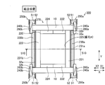
本発明の第3実施形態による縦孔閉塞装置300は、図11に示すように、一対の固定壁10と、枠部220と、一対の可動壁230aおよび230bと、一対のドラム240aおよび一対のドラム240bと、一対の付勢部250aおよび一対の付勢部250bと、一対のケーブル260aおよび一対のケーブル260bとを備えている。
本発明の第3実施形態による縦孔閉塞装置300は、図11に示すように、一対の固定壁10と、枠部220と、一対の可動壁230aおよび230bと、一対のドラム240aおよび一対のドラム240bと、一対の付勢部250aおよび一対の付勢部250bと、一対のケーブル260aおよび一対のケーブル260bとを備えている。
枠部220は、平面視で、縦孔Hを取り囲むように、矩形枠状に形成されている。また、枠部220は、X1側に設けられ、Y方向に延びる枠部分221と、枠部分221のY方向の両端部から、枠部220のX方向の中央部まで、X2側に向かってそれぞれ延びる一対の傾斜枠部分222と、X2側に設けられ、Y方向に延びる枠部分223と、枠部分223のY方向の両端部から、枠部220のX方向の中央部までX1側に向かってそれぞれ延びる一対の傾斜枠部分224とを含んでいる。そして、枠部分221および223と、一対の傾斜枠部分222と、一対の傾斜枠部分224とによって囲まれた部分に、縦孔Hに連通する開口部225が形成されている。
図12に示すように、枠部分221および223は、ほとんど傾斜しておらず、Y方向に沿って略一様の高さ位置に形成されている。一方、一対の傾斜枠部分222は、共に、可動壁230a側の枠部分221(X1側)から枠部220のX方向の中央部(X2側)に向かって、斜め上方(Z1側)に傾斜するように設けられている。また、一対の傾斜枠部分224は、共に、可動壁230b側の枠部分223(X2側)から枠部220のX方向の中央部(X1側)に向かって、斜め上方に傾斜するように設けられている。また、傾斜枠部分222および224の鉛直方向に対する傾斜角θは、約45度である。なお、傾斜角θは、約60度以下であるのが好ましい。
可動壁230aおよび230bは、図11に示すように、矩形形状の立壁部270の対向する2辺を構成するように配置されている。
可動壁230aは、枠部分221のX1側に隣接して設けられている。可動壁230aは、図12に示すように、下端近傍に設けられた回動軸231a周りに回動することによって、壁面が鉛直方向に延びる起立位置と、X2側の壁面が枠部220に当接する倒伏位置とに回動可能なように構成されている。そして、倒伏位置に回動した状態において、可動壁230aのX2側の壁面は、枠部220の一対の傾斜枠部分222の略全面に当接して、枠部220の開口部225のX1側を閉塞するように構成されている。
可動壁230bは、枠部分223のX2側に隣接して設けられている。可動壁230bは、下端近傍に設けられた回動軸231b周りに回動することによって、壁面が鉛直方向に延びる起立位置と、X1側の壁面が枠部220に当接する倒伏位置とに回動可能なように構成されている。そして、倒伏位置において、可動壁230bのX1側の壁面は、枠部220の一対の傾斜枠部分224の略全面に当接して、枠部220の開口部225のX2側を閉塞するように構成されている。この結果、可動壁230aおよび230bにより、枠部220の開口部225が閉塞されることによって、縦孔Hが完全に閉塞されるように構成されている。
一対のドラム240aは、それぞれ、固定壁10のX1側において、一対の固定壁10の上部に取り付けられている。また、一対のドラム240bは、それぞれ、固定壁10のX2側において、一対の固定壁10の上部に取り付けられている。また、図11に示すように、一対の付勢部250aは、それぞれ、一対の固定壁10のX1側の近傍に設けられている。また、一対の付勢部250bは、それぞれ、一対の固定壁10のX2側の近傍に設けられている。また、一対のケーブル260aは、X1側において、可動壁230aと付勢部250aの錘部材51とを接続している。また、一対のケーブル260bは、X2側において、可動壁230bと付勢部250bの錘部材51とを接続している。
これらの結果、縦孔閉塞装置300は、平面視で、Y方向の略中央を通り、X方向に延びる中心線に対して略対称な構造を有するだけでなく、X方向の略中央を通り、Y方向に延びる中心線に対しても略対称な構造を有するように形成されている。
ここで、第3実施形態では、図5に示すように、付勢部250aの錘部材51の付勢力による可動壁230aの起立方向(A1a方向)への回転モーメントM1と、倒伏位置における可動壁230aの自重による倒伏方向(A2a方向)への回転モーメントM2(M2max)との合成モーメントMは、上記第1実施形態と同様に、常に起立方向の回転モーメントになるように構成されている。同様に、付勢部250bの錘部材51の付勢力による可動壁230bの起立方向(A1b方向)への回転モーメントM1と、倒伏位置における可動壁230bの自重による倒伏方向(A2b方向)への回転モーメントM2(M2max)との合成モーメントMは、常に起立方向の回転モーメントになるように構成されている。
(可動壁の回動動作)
上記のように構成されていることによって、第3実施形態における縦孔閉塞装置300の通常状態においては、図12に示すように、可動壁230aに、付勢部250aの錘部材51による付勢力により、可動壁230aの起立方向(A1a方向)への回転モーメントM1が加えられる。これにより、可動壁230aは、通常状態において、起立位置に自動的に位置するように構成されている。同様に、可動壁230bには、付勢部250bの錘部材51による付勢力により、可動壁230bの起立方向(A1b方向)への回転モーメントM1が加えられる。これにより、可動壁230bは、起立位置に自動的に位置するように構成されている。
上記のように構成されていることによって、第3実施形態における縦孔閉塞装置300の通常状態においては、図12に示すように、可動壁230aに、付勢部250aの錘部材51による付勢力により、可動壁230aの起立方向(A1a方向)への回転モーメントM1が加えられる。これにより、可動壁230aは、通常状態において、起立位置に自動的に位置するように構成されている。同様に、可動壁230bには、付勢部250bの錘部材51による付勢力により、可動壁230bの起立方向(A1b方向)への回転モーメントM1が加えられる。これにより、可動壁230bは、起立位置に自動的に位置するように構成されている。
そして、浸水による水圧が可動壁230aのX1側から加えられて、水圧による可動壁230aの倒伏方向(A2a方向)への回転モーメントM2の大きさが、錘部材51による可動壁230aの起立方向(A1a方向)への回転モーメントM1の大きさを超えると、可動壁230aは倒伏位置に回動される。同様に、水圧が可動壁230bのX2側から加えられて、水圧による可動壁230bの倒伏方向(A2b方向)への回転モーメントM2の大きさが、錘部材51による可動壁230bの起立方向(A1b方向)への回転モーメントM1の大きさを超えると、可動壁230bは倒伏位置に回動される。これにより、可動壁230aおよび230bによって、枠部220の開口部225が閉塞されて、縦孔Hが自動的に閉塞される。
その後、可動壁230aが倒伏位置の状態において、浸水による水圧が減少または解消すると、錘部材51の付勢力による可動壁230aの起立方向(A1a方向)への回転モーメントM1により、可動壁230aは起立位置に回動される。同様に、可動壁230bが倒伏位置の状態において、浸水による水圧が減少または解消すると、錘部材51の付勢力による可動壁230bの起立方向(A1b方向)への回転モーメントM1により、可動壁230bは起立位置に回動される。これにより、可動壁230aおよび230bによって、枠部220の開口部225が開放されて、縦孔Hが自動的に開放される。なお、第3実施形態のその他の構成は、上記第1実施形態と同様である。
(第3実施形態の効果)
第3実施形態では、以下のような効果を得ることができる。
第3実施形態では、以下のような効果を得ることができる。
第3実施形態では、上記のように、下部に空間が形成されている縦孔Hの上部に、縦孔Hを閉塞する倒伏位置と縦孔Hを開放する起立位置とに回動可能な可動壁230aおよび230bを設け、可動壁230aおよび230bを、水による水圧により錘部材51の付勢力に抗して倒伏位置に回動されて縦孔Hを閉塞するように構成する。これにより、上記第1実施形態と同様に、縦孔Hを介して水が下部の空間に流れ込むのを抑制することができる。また、可動壁230aおよび230bを、水圧が減少または消失した場合に、錘部材51の付勢力により起立位置に回動されて、起立位置に復帰して縦孔Hを開放するように構成する。これにより、上記第1実施形態と同様に、水圧の状況に応じて、人為的な操作を要すことなく縦孔Hの開閉状態を切り替えることができる。
また、第3実施形態では、可動壁230aおよび230bを、矩形形状の立壁部270の対向する2辺を構成するように配置する。これにより、可動壁が1辺のみを可動壁により構成した場合と比べて、縦孔Hを閉塞させる可動壁230aおよび230bの大きさを小さくすることができる。この結果、縦孔閉塞装置300の小型化を図ることができる。また、開口面積の大きな縦孔Hであっても、2辺を構成する2個の可動壁230aおよび230bにより、縦孔Hを確実に閉塞させることができる。なお、第3実施形態のその他の効果は、上記第1実施形態と同様である。
[第4実施形態]
図5、図13および図14を参照して、本発明の第4実施形態による縦孔閉塞装置400について説明する。この第4実施形態の縦孔閉塞装置400では、第3実施形態の縦孔閉塞装置300の構成の一部を縦孔H内に配置した例について説明する。なお、上記第3実施形態と同様の構成には、第3実施形態と同じ符号を付して図示するとともに説明を省略する。
図5、図13および図14を参照して、本発明の第4実施形態による縦孔閉塞装置400について説明する。この第4実施形態の縦孔閉塞装置400では、第3実施形態の縦孔閉塞装置300の構成の一部を縦孔H内に配置した例について説明する。なお、上記第3実施形態と同様の構成には、第3実施形態と同じ符号を付して図示するとともに説明を省略する。
(縦孔閉塞装置の構成)
本発明の第4実施形態による縦孔閉塞装置400は、図13に示すように、一対の固定壁10と、枠部320と、一対の可動壁330aおよび330bと、一対のドラム240aおよび一対のドラム240bと、一対の補助ドラム341aおよび一対の補助ドラム341bと、一対の付勢部250aおよび一対の付勢部250bと、一対のケーブル360aおよび一対のケーブル360bとを備えている。
本発明の第4実施形態による縦孔閉塞装置400は、図13に示すように、一対の固定壁10と、枠部320と、一対の可動壁330aおよび330bと、一対のドラム240aおよび一対のドラム240bと、一対の補助ドラム341aおよび一対の補助ドラム341bと、一対の付勢部250aおよび一対の付勢部250bと、一対のケーブル360aおよび一対のケーブル360bとを備えている。
枠部320は、縦孔Hの内部における上部(上側部分)において、縦孔Hの内周面に固定されている。また、枠部320は、平面視で、矩形形状の縦孔Hの形状に合わせて、矩形枠状に形成されている。また、枠部320は、平面視で、X1側に設けられ、Y方向に延びる枠部分321と、枠部分321のY方向の両端部から、枠部320のX方向の中央部まで、X2側に向かってそれぞれ延びる一対の傾斜枠部分322と、X2側に設けられ、Y方向に延びる枠部分323と、枠部分323のY方向の両端部から、枠部320のX方向の中央部までX1側に向かってそれぞれ延びる一対の傾斜枠部分324とを含んでいる。そして、枠部分321および323と、一対の傾斜枠部分322と、一対の傾斜枠部分324とに囲まれた部分に開口部325が形成されている。
図14に示すように、枠部分321の上面および一対の傾斜枠部分322は、共に、X1側から枠部320のX方向の中央部(X2側)に向かって、斜め上方に傾斜するように設けられている。また、枠部分323の上面および一対の傾斜枠部分324は、共に、X2側から枠部320のX方向の中央部(X1側)に向かって、斜め上方に傾斜するように設けられている。また、枠部分321の上面、傾斜枠部分322、枠部分323の上面および傾斜枠部分324の鉛直方向に対する傾斜角θは、約45度である。なお、傾斜角θは、約60度以下であるのが好ましい。
また、枠部分321および323の上面の近傍には、それぞれ、地下構造物内を通り、地上に接続された排水孔CaおよびCbが設けられている。この排水孔CaおよびCbは、枠部分321および323の傾斜する上面上に溜まった水を、図示しない排水設備を用いて地上に排出するために設けられている。
可動壁330aは、縦孔Hの内部における上部(上側部分)である、枠部分321のX1側の上方に隣接して設けられている。可動壁330aは、下端近傍に設けられた回動軸331a周りに回動することによって、壁面が縦孔Hの延びる鉛直方向に沿う起立位置と、X2側の壁面が枠部320に当接する倒伏位置とに回動可能なように構成されている。そして、倒伏位置に回動した状態において、可動壁330aのX2側の壁面は、枠部320の一対の傾斜枠部分322の略全面に当接して、枠部320の開口部325のX1側を閉塞するように構成されている。
可動壁330bは、縦孔Hの内部における上部(上側部分)である、枠部分323のX2側の上方に隣接して設けられている。可動壁330bは、下端近傍に設けられた回動軸331b周りに回動することによって、壁面が縦孔Hの延びる鉛直方向に沿う起立位置と、X1側の壁面が枠部320に当接する倒伏位置とに回動可能なように構成されている。そして、倒伏位置に回動した状態において、可動壁330bのX1側の壁面は、枠部320の一対の傾斜枠部分324の略全面に当接して、枠部320の開口部325のX2側を閉塞するように構成されている。この結果、可動壁330aおよび330bの両方により、枠部320の開口部325が閉塞されることによって、縦孔Hが完全に閉塞されるように構成されている。
また、可動壁330aおよび330bの上端面は、地上面Sよりも上方(Z1側)に位置するように構成されている。これにより、浸水時の水が、可動壁330aおよび330bの地上に露出する壁面に当接することによって、水圧が可動壁330aおよび330bに加えられるように構成されている。
一対の補助ドラム341aは、X1側において、それぞれ、一対のドラム240aの下方(Z2側)に配置されている。また、一対の補助ドラム341aには、それぞれ、一対のケーブル360aが掛けられている。同様に、一対の補助ドラム341bは、X2側において、それぞれ、一対のドラム240bの下方に配置されている。また、一対の補助ドラム341bには、それぞれ、一対のケーブル360bが掛けられている。また、一対のケーブル360aは、X1側において、それぞれ、一対のドラム240aおよび一対の補助ドラム341aを介して、可動壁330aと付勢部250aの錘部材51とを接続している。同様に、一対のケーブル360bは、X2側において、それぞれ、一対のドラム240bおよび一対の補助ドラム341bを介して、可動壁330bと付勢部250bの錘部材51とを接続している。
これらの結果、縦孔閉塞装置400は、平面視で、Y方向の略中央を通り、X方向に延びる中心線に対して略対称な構造を有するだけでなく、X方向の略中央を通り、Y方向に延びる中心線に対しても略対称な構造を有するように形成されている。
ここで、第4実施形態では、図5に示すように、付勢部250aの錘部材51の付勢力による可動壁330aの起立方向(A1a方向)への回転モーメントM1と、倒伏位置における可動壁330aの自重による倒伏方向(A2a方向)への回転モーメントM2(M2max)との合成モーメントMは、上記第1実施形態および第3実施形態と同様に、常に起立方向の回転モーメントになるように構成されている。同様に、付勢部250bの錘部材51の付勢力による可動壁330bの起立方向(A1b方向)への回転モーメントM1と、倒伏位置における可動壁330bの自重による倒伏方向(A2b方向)への回転モーメントM2(M2max)との合成モーメントMは、常に起立方向の回転モーメントになるように構成されている。なお、第4実施形態のその他の構成および可動壁330aおよび330bの回動動作は、上記第3実施形態と同様である。
(第4実施形態の効果)
第4実施形態では、以下のような効果を得ることができる。
第4実施形態では、以下のような効果を得ることができる。
第4実施形態では、上記のように、下部に空間が形成されている縦孔Hの内部における上部に、縦孔Hを閉塞する倒伏位置と縦孔Hを開放する起立位置とに回動可能な可動壁330aおよび330bを設け、可動壁330aおよび330bを、水による水圧により錘部材51の付勢力に抗して倒伏位置に回動されて縦孔Hを閉塞するように構成する。これにより、上記第3実施形態と同様に、縦孔Hを介して水が下部の空間に流れ込むのを抑制することができる。また、可動壁330aおよび330bを、水圧が減少または消失した場合に、錘部材51の付勢力により起立位置に回動されて、起立位置に復帰して縦孔Hを開放するように構成する。これにより、上記第3実施形態と同様に、水圧の状況に応じて、人為的な操作を要すことなく縦孔Hの開閉状態を切り替えることができる。
また、第4実施形態では、縦孔Hの内部に、枠部320と、可動壁330aおよび330bとを配置することによって、地上に枠部320および可動壁330aおよび330bを配置する空間を確保する必要がないので、地上部分における縦孔閉塞装置400の占有空間をより小さくすることができる。なお、第4実施形態のその他の効果は、上記第3実施形態と同様である。
[変形例]
なお、今回開示された実施形態は、すべての点で例示であって制限的なものではないと考えられるべきである。本発明の範囲は、上記した実施形態の説明ではなく特許請求の範囲によって示され、さらに特許請求の範囲と均等の意味および範囲内でのすべての変更(変形例)が含まれる。
なお、今回開示された実施形態は、すべての点で例示であって制限的なものではないと考えられるべきである。本発明の範囲は、上記した実施形態の説明ではなく特許請求の範囲によって示され、さらに特許請求の範囲と均等の意味および範囲内でのすべての変更(変形例)が含まれる。
たとえば、上記第1~第4実施形態では、地下街および地下鉄のトンネルなどの地下構造物の空間と地上とを接続する縦孔Hに本発明の縦孔閉塞装置100(200、300、400)を適用した例を示したが、本発明はこれに限られない。本発明の縦孔閉塞装置は、地下空間と地上とを接続する縦孔に適用される場合に限られず、地上に設けられた構造物において、下階と上階(屋上も含む)とを接続する縦孔に、本発明の縦孔閉塞装置を適用してもよい。これにより、上階において漏水などが発生した際に、本発明の縦孔閉塞装置により、縦孔を介して、液体が下階に流れ込むのを抑制することが可能である。
また、上記第1~第4実施形態では、縦孔Hが鉛直方向に延びる例を示したが、本発明はこれに限られない。本発明では、縦孔は、鉛直方向に傾斜して延びるように形成されていてもよい。また、縦孔の一部が鉛直方向に直交する方向に延びる部分を有していてもよい。
また、上記第1~第4実施形態では、特許請求の範囲の「液体」が「水」である例を示したが、本発明はこれに限られない。特許請求の範囲の「液体」は液体であれば水に限られず、たとえば、油および液状の薬剤などであってもよい。
また、上記第1~第4実施形態では、特許請求の範囲の「付勢部材」として、錘部材51(151)を用いた例を示したが、本発明はこれに限られない。本発明では、たとえば、付勢部材として、ばねを用いてもよい。なお、付勢部材としてばねを用いることによって、付勢力を線形に変化させることが可能である。また、ばね定数の異なるばねを複数種類用いてもよい。また、錘部材とばねとを併用してもよい。この際、図9に示すような理想的な合成モーメント(傾斜角に因らず略一定の回転モーメント)に近づくように、錘部材とばねとを組み合わせるのがよい。
また、上記第2実施形態では、複数(3個)の錘151a、151bおよび151cのうち、錘151aの重量は、錘151bの重量よりも大きく、錘151bの重量は、錘151cの重量よりも大きくなるように構成した例を示したが、本発明はこれに限られない。本発明では、たとえば、複数の錘の重量を略同一にしてもよい。
また、上記第1~第4実施形態では、縦孔Hが、平面視で、矩形形状である例を示したが、本発明はこれに限られない。本発明では、縦孔の平面形状は特に限定されない。たとえば、縦孔は、平面視で、円形状、楕円形状、多角形形状などであってもよい。
また、上記第1~第4実施形態では、可動壁30(230a、230b、330a、330b)が平板状である例を示したが、本発明はこれに限られない。本発明では、可動壁が縦孔を閉塞することが可能であれば、可動壁の形状は特に限定されない。
また、上記第1~第4実施形態では、枠部20(220、320)に可動壁30(230a、230b、330a、330b)が当接する例を示したが、本発明はこれに限られない。本発明では、枠部を設けなくてもよい。この場合、可動壁を、縦孔の開口形状よりも大きく形成することによって、可動壁が直接的に縦孔を閉塞するように構成するのが好ましい。
また、上記第1~第4実施形態では、枠部20(220、320)が傾斜する部分を有する例を示したが、本発明はこれに限られない。本発明では、枠部を傾斜させずに、水平面状に配置してもよい。
また、上記第1~第4実施形態では、鉛直方向に働く錘部材51の付勢力の方向を可動壁30を起立方向(A1方向)にするためにドラム40(240a、240b)を用いた例を示したが、本発明はこれに限られない。たとえば、転向滑車を用いて、鉛直方向に働く錘部材の付勢力の方向を可動壁を起立方向にしてもよい。
また、上記第1~第4実施形態では、1個の可動壁30(230a、230b、330a、330b)に対して、一対の付勢部50(150,250a、250b)を設けた例を示したが、本発明はこれに限られない。本発明では、1個の可動壁に対して、一対の付勢部(付勢部材)を設けずに、1個の可動壁に対して1個の付勢部(付勢部材)を設けてもよい。この場合、図2、図11および図13において、Y方向の一方側の付勢部のみを残し、他方側の付勢部を削除すればよい。また、1個の可動壁に対して3個以上の付勢部(付勢部材)を設けてもよい。
10 固定壁
20、220、320 枠部
23 固定枠部分(固定壁、支持壁)
24、225、325 開口部
30、230a、230b、330a、330b 可動壁
51、151 錘部材(付勢部材)
70、270 立壁部
100、200、300、400 縦孔閉塞装置
151a、151b、151c 錘
H 縦孔
20、220、320 枠部
23 固定枠部分(固定壁、支持壁)
24、225、325 開口部
30、230a、230b、330a、330b 可動壁
51、151 錘部材(付勢部材)
70、270 立壁部
100、200、300、400 縦孔閉塞装置
151a、151b、151c 錘
H 縦孔
Claims (6)
- 下部に空間が形成されている縦孔(H)の上部に設けられ、前記縦孔を閉塞する倒伏位置と前記縦孔を開放する起立位置とに回動可能な可動壁(30)と、
前記可動壁を前記起立位置に位置するように付勢する付勢部材(51)と、を備え、
前記可動壁は、液体による液体圧により前記付勢部材の付勢力に抗して前記倒伏位置に回動されて前記縦孔を閉塞するとともに、前記液体圧が減少または消失した場合に、前記付勢部材の付勢力により前記起立位置に回動されて、前記起立位置に復帰して前記縦孔を開放するように構成されている、縦孔閉塞装置(100)。 - 前記縦孔の上部に設けられ、平面視で、矩形形状を有する立壁部(70)をさらに備え、
前記可動壁は、平面視で、矩形形状の前記立壁部の少なくとも1辺を構成するように配置されている、請求項1に記載の縦孔閉塞装置。 - 前記縦孔の上部において、前記可動壁側から前記可動壁とは反対側に向かって斜め上方に傾斜して設けられ、前記縦孔に対応する開口部(24)を有する枠部(20)をさらに備え、
前記可動壁は、前記倒伏位置において前記枠部の前記開口部を閉塞することによって前記縦孔を閉塞するように構成されている、請求項1に記載の縦孔閉塞装置。 - 前記枠部を傾斜した状態で支持する支持壁(23)をさらに備え、
前記支持壁は、前記縦孔の上部に設けられた立壁部の固定壁(10)を構成するように配置されている、請求項3に記載の縦孔閉塞装置。 - 前記付勢部材は、錘部材(151)を含み、
前記錘部材は、複数の錘(151a、151b、151c)を含むとともに、前記可動壁が前記倒伏位置から前記起立位置に向かうにしたがって、前記複数の錘のうちの付勢力に寄与する前記錘の個数が減少することによって、付勢力が徐々に弱くなるように構成されている、請求項1に記載の縦孔閉塞装置。 - 前記可動壁は、平面視で、矩形形状の前記立壁部の対向する2辺を構成するように配置されている、請求項2に記載の縦孔閉塞装置。
Applications Claiming Priority (2)
| Application Number | Priority Date | Filing Date | Title |
|---|---|---|---|
| JP2016076782A JP2017186809A (ja) | 2016-04-06 | 2016-04-06 | 縦孔閉塞装置 |
| JP2016-076782 | 2016-04-06 |
Publications (1)
| Publication Number | Publication Date |
|---|---|
| WO2017175459A1 true WO2017175459A1 (ja) | 2017-10-12 |
Family
ID=60000734
Family Applications (1)
| Application Number | Title | Priority Date | Filing Date |
|---|---|---|---|
| PCT/JP2017/003356 Ceased WO2017175459A1 (ja) | 2016-04-06 | 2017-01-31 | 縦孔閉塞装置 |
Country Status (2)
| Country | Link |
|---|---|
| JP (1) | JP2017186809A (ja) |
| WO (1) | WO2017175459A1 (ja) |
Families Citing this family (1)
| Publication number | Priority date | Publication date | Assignee | Title |
|---|---|---|---|---|
| JP6840657B2 (ja) * | 2017-12-13 | 2021-03-10 | 日立造船株式会社 | 起伏ゲート |
Citations (4)
| Publication number | Priority date | Publication date | Assignee | Title |
|---|---|---|---|---|
| JP2001140556A (ja) * | 1999-11-10 | 2001-05-22 | Kongo Sangyo Kk | ド ア |
| JP2003214676A (ja) * | 2002-01-25 | 2003-07-30 | Tokyo Metropolis | 換気口構造 |
| JP2014199144A (ja) * | 2013-03-29 | 2014-10-23 | 日立造船株式会社 | 管路止水装置 |
| US9004814B2 (en) * | 2013-02-25 | 2015-04-14 | New York City Transit Authority | Passive underground flood protection |
-
2016
- 2016-04-06 JP JP2016076782A patent/JP2017186809A/ja active Pending
-
2017
- 2017-01-31 WO PCT/JP2017/003356 patent/WO2017175459A1/ja not_active Ceased
Patent Citations (4)
| Publication number | Priority date | Publication date | Assignee | Title |
|---|---|---|---|---|
| JP2001140556A (ja) * | 1999-11-10 | 2001-05-22 | Kongo Sangyo Kk | ド ア |
| JP2003214676A (ja) * | 2002-01-25 | 2003-07-30 | Tokyo Metropolis | 換気口構造 |
| US9004814B2 (en) * | 2013-02-25 | 2015-04-14 | New York City Transit Authority | Passive underground flood protection |
| JP2014199144A (ja) * | 2013-03-29 | 2014-10-23 | 日立造船株式会社 | 管路止水装置 |
Also Published As
| Publication number | Publication date |
|---|---|
| JP2017186809A (ja) | 2017-10-12 |
Similar Documents
| Publication | Publication Date | Title |
|---|---|---|
| CN102713075B (zh) | 浮体连结式铰链式闸门 | |
| US7323791B2 (en) | Louvered horizontal wind turbine | |
| CN108285114B (zh) | 水平铰接平台臂组件 | |
| JP5905152B1 (ja) | フラップゲート | |
| WO2017175459A1 (ja) | 縦孔閉塞装置 | |
| JP2016050454A (ja) | 連絡橋構造体 | |
| US10435908B2 (en) | Flood protection for underground air vents | |
| JP5503074B1 (ja) | フラップゲート | |
| JP4203798B2 (ja) | 回転式ゲート | |
| KR101440810B1 (ko) | 바람 유입량 조절 기능을 가지는 풍력 발전장치 | |
| JP4987751B2 (ja) | フラップゲート | |
| KR200401338Y1 (ko) | 받침틀식 가동보 | |
| JP2015212517A (ja) | 防波扉および防波扉設置方法 | |
| JP5203536B1 (ja) | フラップゲート | |
| JP5781137B2 (ja) | 防波扉 | |
| KR102021759B1 (ko) | 웨이트붙이 볼밸브 및 이를 구비한 배관연결장치 | |
| KR100912197B1 (ko) | 접철 가능한 가동보 개폐장치 | |
| JP2016050455A (ja) | 連絡橋 | |
| CN104696532A (zh) | 卧式旋转封堵门 | |
| KR101397628B1 (ko) | 2중회동링크형 플랩밸브 | |
| KR101313372B1 (ko) | 비상다리가 구성되어 있는 가동보 | |
| JP2010185183A (ja) | 簡易チェックゲート | |
| JP7546301B2 (ja) | ダンパ装置 | |
| KR102820376B1 (ko) | 유속 조절부가 구비된 조류발전 듀얼 터빈 시스템 및 운전방법 | |
| JPH0339513A (ja) | 洪水に対応する自動堰上げゲート |
Legal Events
| Date | Code | Title | Description |
|---|---|---|---|
| NENP | Non-entry into the national phase |
Ref country code: DE |
|
| 121 | Ep: the epo has been informed by wipo that ep was designated in this application |
Ref document number: 17778838 Country of ref document: EP Kind code of ref document: A1 |
|
| 122 | Ep: pct application non-entry in european phase |
Ref document number: 17778838 Country of ref document: EP Kind code of ref document: A1 |