WO2017175340A1 - 最適化装置及びそれを備えた垂直型多関節ロボット - Google Patents
最適化装置及びそれを備えた垂直型多関節ロボット Download PDFInfo
- Publication number
- WO2017175340A1 WO2017175340A1 PCT/JP2016/061315 JP2016061315W WO2017175340A1 WO 2017175340 A1 WO2017175340 A1 WO 2017175340A1 JP 2016061315 W JP2016061315 W JP 2016061315W WO 2017175340 A1 WO2017175340 A1 WO 2017175340A1
- Authority
- WO
- WIPO (PCT)
- Prior art keywords
- robot
- vibration
- joint
- articulated robot
- tip
- Prior art date
- Legal status (The legal status is an assumption and is not a legal conclusion. Google has not performed a legal analysis and makes no representation as to the accuracy of the status listed.)
- Ceased
Links
Images


Classifications
-
- B—PERFORMING OPERATIONS; TRANSPORTING
- B25—HAND TOOLS; PORTABLE POWER-DRIVEN TOOLS; MANIPULATORS
- B25J—MANIPULATORS; CHAMBERS PROVIDED WITH MANIPULATION DEVICES
- B25J13/00—Controls for manipulators
- B25J13/08—Controls for manipulators by means of sensing devices, e.g. viewing or touching devices
Definitions
- the present invention relates to an optimization device and a vertical articulated robot including the optimization device.
- Vertical articulated robots are used in various production technology fields including automobiles.
- a vertical articulated robot a plurality of robot arms are connected via joints, and each robot arm is operated by a motor attached to each joint, thereby moving the end effector at the tip of the robot to a desired position.
- Patent Document 1 Patent Document 1
- the present invention has been made to solve the above-mentioned problems, and has as its main object to improve the accuracy of the work of the vertical articulated robot.
- the optimization apparatus of the present invention Optimum operation of a vertical multi-joint robot that connects multiple robot moving parts via joints and moves the robot tip to a desired position by operating each robot moving part with a motor attached to each joint
- a device that Coordinate acquisition means for acquiring the coordinates of at least the movement source and the movement destination of the robot tip; An operation locus setting means for setting an operation locus based on the coordinates of the movement source and the movement destination; An operation condition setting means for setting an operation condition of the robot tip; Based on the motion trajectory and the motion conditions, target position information of the robot tip with respect to the time during the motion of the articulated robot is derived, and a dynamic characteristic model according to the inertia value of the motion trajectory and the articulated robot Vibration deriving means for deriving vibration of the robot tip from the target position information based on operation control; It is determined whether or not the vibration of the robot tip falls within a predetermined allowable range.
- operation condition setting means for setting the operation condition at that time to an optimal operation condition; It is equipped with.
- This optimization device derives the vibration of the robot tip from the target position information of each joint based on the dynamic characteristic model and motion control of the articulated robot, and determines whether the vibration falls within a predetermined allowable range. Make a decision. If the result of the determination is negative, this optimizing device sets at least one of the set operating conditions to a low value, derives the vibration of the robot tip, performs the determination again, and the result of the determination is affirmative If so, the operating condition at that time is set to the optimum operating condition.
- the operating conditions are set so that the vibration at the tip of the robot that affects the work accuracy falls within an allowable range. Therefore, according to the present invention, it is possible to improve the accuracy of the work of the vertical articulated robot.
- the motion trajectory setting means may set the motion trajectory so that an inertia value according to the posture of the articulated robot is minimized when setting the motion trajectory.
- the operation conditions are set under such a condition that the vertical articulated robot can maintain the minimum performance for every operation posture. For this reason, even in a robot posture capable of high-speed operation, an operation condition that assumes the worst condition is sometimes set.
- the motion trajectory is set so that the inertia value due to the posture of the articulated robot is minimized. Therefore, as compared with the case where the inertia value is large, it is possible to make the operation condition as fast as possible within a range not exceeding the operation limit of the articulated robot. That is, not only high-precision work but also high speed can be achieved.
- the target position information of the joint closest to the robot tip may be used as the target position information of the robot tip. In this way, the present invention can be applied even when the position detection sensor is not provided at the tip of the articulated robot.
- the operating condition may be a moving speed and an acceleration / deceleration. Since the working speed depends on the moving speed and the acceleration / deceleration speed, it is preferable to use these as operating conditions.
- the vertical articulated robot of the present invention is equipped with the optimization device described above.
- the optimization device described above since the optimum operation condition is set by the optimization device described above, it is possible to improve the work accuracy.
- FIG. 1 is a perspective view of an articulated robot 10.
- FIG. The block diagram showing the electrical connection of the controller 60.
- FIG. The flowchart of an operation condition optimization process routine. Explanatory drawing which shows an example of the control system which combined the whole dynamic characteristic model and the control performed during operation
- FIG. 1 is a perspective view of a vertical articulated robot 10 according to the present embodiment
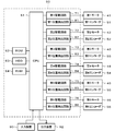
- FIG. 2 is a block diagram showing electrical connection of a controller 60.
- the vertical articulated robot 10 includes six robot movable parts (shoulder 14, lower arm 16, first upper arm 18, second upper arm 20, wrist 22 and connector 24) and a controller 60. is there.
- the six robot movable parts are connected on the cylindrical base 12.
- the shoulder 14 is connected to the upper surface of the base 12 via the first joint 31 so as to be rotatable around the vertical axis 31a.
- the lower end of the lower arm 16 is connected to the shoulder 14 via a second joint 32 so as to be rotatable around a horizontal axis 32a.
- a base end portion of the first upper arm 18 is connected to an upper end portion of the lower arm 16 via a third joint 33 so as to be rotatable around a horizontal shaft 33a.
- a proximal end portion of the second upper arm 20 is connected to a distal end portion of the first upper arm 18 via a fourth joint 34 so as to be rotatable around a shaft 34 a extending in the longitudinal direction of the second upper arm 20.
- a proximal end portion of the wrist 22 is connected to a distal end portion of the second upper arm 20 via a fifth joint 35 so as to be rotatable around a shaft 35 a extending in a direction perpendicular to the longitudinal direction of the second upper arm 20.
- the connector 24 is connected to the distal end portion of the wrist 22 through a sixth joint 36 so as to be rotatable around a shaft 36a extending in a direction orthogonal to the shaft 35a.
- the first joint 31 includes a first motor 41 that rotationally drives the shoulder 14, and the second joint 32 includes a second motor 42 that rotationally drives the lower arm 16.
- the third joint 33 incorporates a third motor 43 that rotationally drives the first upper arm 18, and the fourth joint 34 incorporates a fourth motor 44 that rotationally drives the second upper arm 20.
- the fifth joint 35 incorporates a fifth motor 45 that rotationally drives the wrist 22, and the sixth joint 36 incorporates a sixth motor 46 that rotationally drives the connector 24.
- the first to sixth motors 41 to 46 include first to sixth encoders 51 to 56 (see FIG. 2), respectively. In this embodiment, a servo motor is used as the motor, and a rotary encoder is used as the encoder.
- the controller 60 is a device that controls the operation of the robot movable part of the articulated robot 10. As shown in FIG. 2, the controller 60 is configured as a microprocessor centered on a CPU 61, and includes a ROM 62 for storing processing programs, an HDD 63 for storing various data, a RAM 64 used as a work area, and the like. These are electrically connected by a bus (not shown).
- the CPU 61 is connected to first to sixth drive circuits 71 to 76, first to sixth position detection circuits 81 to 86, an input device 90, and an output device 92.
- the first to sixth drive circuits 71 to 76 are provided corresponding to the first to sixth motors 41 to 46, respectively.
- the first to sixth drive circuits 71 to 76 output electrical signals based on the command signal from the CPU 61 to the corresponding first to sixth motors 41 to 46, respectively.
- the first to sixth position detection circuits 81 to 86 are for detecting the position of each robot movable portion, and are provided corresponding to the first to sixth encoders 51 to 56, respectively.
- the first to sixth position detection circuits 81 to 86 detect the angular positions of the first to sixth motors 41 to 46 based on the detection signals input from the corresponding first to sixth encoders 51 to 56, respectively. It outputs to CPU61.
- the input device 90 is a keyboard or a mouse on which an operator performs an input operation.
- the output device 92 is a display that displays various data as visual information such as images.
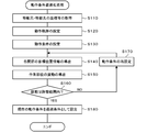
- FIG. 3 is a flowchart of the operating condition optimization processing routine.
- the CPU 61 of the controller 60 obtains the coordinates of the movement source, the movement destination, and the relay passing point of the work site of the end effector 26 (for example, the site that grips the part) and the mass of the object to be moved (step S110).
- the movement target object is an object that is held by the work site of the end effector 26 and is carried from the movement source to the movement destination.
- the CPU 61 may acquire data input by the operator via the input device 90, or data stored in advance in a storage device such as the HDD 63 may be used.
- the CPU 61 may read and acquire the information.
- the CPU 61 sets an operation locus (step S120). Specifically, the CPU 61 sets the operation locus of the work part of the end effector 26 based on the coordinates of the movement source, the movement destination, and the relay passing point of the work part of the end effector 26. For example, the CPU 61 calculates, as the position coordinates of the work site of the end effector 26 for each sampling time (several msec), the operation trajectory from when the work site of the end effector 26 reaches the destination through the relay passing point. To do. The motion trajectory is set so that the motion inertia (inertia value) is minimized. For example, as shown in FIG.
- the movement source of the work site of the end effector 26 is such that the lower arm 16 slightly tilts backward from the normal direction of the floor surface, and the first and second upper arms 18 and 20 are in contact with the floor surface. Suppose that they are parallel. Further, the movement destination of the work site of the end effector 26 from the state of FIG. 1 is that the first and second upper arms 18 and 20 are parallel to the floor surface, and the lower arm 16 is forward from the normal direction of the floor surface. It is assumed that the position is a large (for example, 60 °) inclination and the shoulder 14 is rotated (for example, 120 ° rightward). In this case, as the motion trajectory candidates, the trajectory A in which the lower arm 16 is largely tilted forward after turning the shoulder 14 first from the state of FIG.
- the lower arm 16 is largely tilted forward from the state of FIG. Assume that there are two traces B that turn the shoulder.
- the movement inertia becomes smaller as the distance from the turning axis to the end effector 26 when the end effector 26 turns is shorter. This distance is shorter on the locus A. Therefore, the trajectory A is set as the motion trajectory that minimizes the motion inertia.
- the CPU 61 sets operating conditions (step S130).
- the movement speed and acceleration / deceleration of the work site of the end effector 26 are set as the operation conditions.
- the CPU 61 moves while maintaining the speed before reaching the destination after the work site of the stopped end effector 26 has accelerated from the source to reach a certain speed, and decelerates before the destination.
- the maximum moving speed and acceleration / deceleration are automatically set within a range not exceeding the operation limit of the end effector 26.
- the operating conditions may be input by the operator via the input device 90.
- the CPU 61 derives target position information of each joint (step S140). Specifically, the CPU 61 derives target position information of each joint by solving inverse kinematics based on the motion trajectory and motion conditions. Inverse kinematics is a well-known technique in which, when the position of the work site of the end effector 26 is determined, the position information of each joint is inversely calculated in order to realize it.
- a target angle position for each sampling time is derived as target position information for each joint.
- the CPU 61 derives the vibration of the work site of the end effector 26 (step S150). Specifically, the CPU 61 uses a control system that combines the overall dynamic characteristic model of the multi-joint robot 10 and the control executed during the operation, based on the target angular position of the work site of the end effector 26. The vibration of the work site is virtually derived. As the entire dynamic characteristic model, a model in an operation locus in which the inertia value determined by the posture of the articulated robot 10 is minimized is used.
- the dynamic characteristic model includes the frictional force of each joint 31 to 36 of the multi-joint robot 10 when the work site of the end effector 26 moves along the motion locus, and each robot movable part (shoulder 14, lower arm 16, The first upper arm 18, the second upper arm 20, the wrist 22 and the connector 24) are used in consideration of the rigidity and the mass of the object to be moved.
- the details of the dynamic characteristic model can be calculated mathematically as described in, for example, the book “Introduction to Mode Analysis” (Akio Nagamatsu, published by Corona Co., Ltd.).
- FIG. 4 shows an example of a control system that combines the entire dynamic characteristic model and the control executed during operation.
- the control system shown in FIG. 4 is a general position feedback control circuit for deriving the position of the work site of the end effector 26 when the position control is executed.
- the deviation between the position command r (target angular position of the sixth joint 36) and the encoder position x (position obtained from the sixth encoder 56) is transferred to the first block B1 having the feedback control transfer characteristic C.
- the torque command ⁇ is output from the first block B1.
- the transfer characteristic C of the feedback control is exemplified by the case where the PID control is used as shown in the equation in FIG. 4, but is not particularly limited thereto, and for example, PI control may be used.
- the torque command ⁇ output from the first block B1 is input to the second block B2 having the transfer characteristic P of the dynamic characteristic model, and the encoder position x is output from the second block B2.
- the transfer characteristic P of the dynamic characteristic model is illustrated as a second-order transfer function as shown in the equation in FIG. 4, it is not particularly limited to this.
- the encoder position x is a detection signal of the sixth encoder 56 attached to the sixth joint 36 closest to the work site of the end effector 26.
- the torque command ⁇ output from the first block B1 is input to the third block B3 having the transfer characteristic P * of the dynamic characteristic model, and the position x of the work site of the end effector 26 from the third block B3. * Is output. As shown in the equation in FIG.
- the transfer characteristic P * of the dynamic characteristic model is illustrated as a second-order transfer function like the transfer characteristic P, but is not particularly limited thereto. . Since the end effector 26 does not have an encoder (sensor), the target angular position of the sixth joint 36 and the encoder position x obtained from the sixth encoder 56 were substituted for the position feedback control.
- the vibration of the work site can be derived from the transition of the position x * of the work site of the end effector 26 obtained by this control system for each sampling time. For example, if a graph in which the horizontal axis represents time and the vertical axis represents the position x * is created, the amplitude and period of vibration can be derived.
- the CPU 61 determines whether or not the vibration is within an allowable range (step S160). Specifically, the CPU 61 determines whether or not the vibration amplitude falls within an allowable range. The allowable range is set in advance according to the work accuracy. If the amplitude of vibration does not fall within the allowable range, the CPU 61 resets the operating conditions (step S170), and repeats the processing after step S140. When resetting the operating conditions, the CPU 61 resets at least one of the speed and the acceleration / deceleration to be lower than the current set value. This is because vibration depends on speed and acceleration / deceleration. On the other hand, if the amplitude of vibration falls within the allowable range, the CPU 61 sets the current operating condition as the optimal operating condition (step S180), and ends this routine.
- the controller 60 of this embodiment corresponds to the optimization device of the present invention
- the shoulder 14, the lower arm 16, the first upper arm 18, the second upper arm 20, the wrist 22 and the connector 24 correspond to a robot movable part
- the first to sixth joints 31 to 36 correspond to joints
- the first to sixth motors 41 to 46 correspond to motors
- the work site of the end effector 26 corresponds to the tip of the robot.
- the CPU 61 of the controller 60 corresponds to a coordinate acquisition unit, an operation locus setting unit, an operation condition setting unit, a vibration derivation unit, and an operation condition setting unit.
- the operation conditions are set so that the vibration of the work part of the end effector 26 that affects the work accuracy falls within the allowable range. Accuracy can be improved.
- the operation conditions are set under such a condition that the articulated robot 10 can maintain the minimum performance for every operation posture. For this reason, even in a robot posture capable of high-speed operation, an operation condition that assumes the worst condition is sometimes set.
- the CPU 61 sets the motion trajectory so that the inertia value due to the posture of the articulated robot 10 is minimized. Therefore, as compared with the case where the inertia value is large, the operation condition can be made as fast as possible within a range not exceeding the operation limit of the articulated robot 10. That is, not only high-precision work but also high-speed work can be achieved.
- the CPU 61 performs control by substituting the target position information of the sixth encoder 56 of the sixth joint 36 closest to the work site as the target position information of the work site of the end effector 26. Therefore, the present invention can be applied even when a position detection sensor is not provided at the work site of the end effector 26 of the articulated robot 10.
- moving speed and acceleration / deceleration are employed as the operating conditions of the work site of the end effector 26. Since the work speed depends on the moving speed and acceleration / deceleration speed of the work site, it is preferable to use these as operating conditions.
- the multi-joint robot 10 includes a controller 60 that executes the above-described operation condition optimization processing routine.
- the controller 60 since the optimum operating condition is set by the controller 60, it is possible to achieve high accuracy and high speed of work. Further, if the operator sets the coordinates of the movement source / destination and the allowable range of vibration via the input device 90, the controller 60 automatically sets the optimum operating condition and actually ends with the operating condition. Each robot movable part can be controlled to perform work using the effector 26.
- the motion trajectory that minimizes the motion inertia is set, but the motion trajectory may be set without particularly considering the motion inertia.
- the working speed is reduced as compared with the above-described embodiment, the working accuracy can be increased.
- the angular position is used as the target position information of each joint, but angular velocity or angular acceleration may be used in addition to the angular position.
- the angular velocity can be derived if the angular position for each sampling time is known, and the angular acceleration can be derived if the angular velocity for each sampling time is known.
- the target position information of the sixth joint 36 closest to the work site is substituted as the target position information of the work site of the end effector 26.
- the work site of the end effector 26 has a position detection sensor.
- the feedback control may be performed using the target position information of the work site of the end effector 26 itself.
- step S160 of the above-described embodiment it is determined whether or not the vibration amplitude falls within the allowable range. However, instead of or in addition to the vibration amplitude, it is determined whether or not the vibration period falls within the allowable range. May be.
- the mass of the moving target object is acquired and the dynamic characteristic model corresponding to the mass is used.
- the mass of the moving target object is negligibly small compared to the end effector 26, It is not necessary to consider the mass of the object to be moved.
- the case where the controller 60 as the optimization device is mounted on the articulated robot 10 is exemplified, but such a controller 60 may be mounted on the simulation device.
- the motion of the articulated robot 10 that employs the optimal operating conditions set by the controller 60 may be displayed as a moving image on the display of the simulation apparatus.
- the operator may confirm interference between the articulated robot 10 and the devices around it.
- the operating condition where the working speed is as high as possible and the vibration is within the allowable range is set as the optimum operating condition.
- the torque of each motor 41 to 46 of each joint 31 to 36 is derived.
- the derived torque and the permissible range of each of the motors 41 to 46 may be compared, and an operation condition that generates a torque that falls within the permissible range with as large a value as possible may be set as the optimum operation condition.
- optimal operating conditions may be set in consideration of both vibration and torque.
- the present invention can be used for a vertical articulated robot.
Landscapes
- Engineering & Computer Science (AREA)
- Human Computer Interaction (AREA)
- Robotics (AREA)
- Mechanical Engineering (AREA)
- Manipulator (AREA)
- Numerical Control (AREA)
Abstract
垂直型の多関節ロボット(10)のコントローラ(60)は、動特性モデルと動作制御とに基づいて各関節(31~36)の目標位置情報からエンドエフェクタ(26)の作業部位(ロボット先端)の振動を導出し、その振動が予め定められた許容範囲に収まるか否かの判定を行う。コントローラ(60)は、判定の結果が否定だったならば、設定された動作条件の少なくとも一つを低い値に設定してロボット先端の振動を導出して再び判定を行い、判定の結果が肯定だったならば、そのときの動作条件を最適な動作条件に設定する。このように、作業精度に影響を与えるエンドエフェクタ(26)の振動が許容範囲に収まるように動作条件を設定するため、多関節ロボット(10)の作業の高精度化を図ることができる。
Description
本発明は、最適化装置及びそれを備えた垂直型多関節ロボットに関する。
垂直型多関節ロボットは、自動車をはじめとした様々な生産技術分野において活用されている。一般に、垂直型多関節ロボットは、複数のロボットアームが関節を介して連結されると共に各関節に取り付けられたモータによって各ロボットアームを作動させることにより、ロボット先端のエンドエフェクタを所望の位置へ移動する(特許文献1)。
この種の垂直型多関節ロボットは、スカラロボットやパラレルリンクロボットなどと比べて剛性が低く、さらに動作姿勢ごとの機械的な特性の変化が大きいため、作業の高精度化を図るのが難しい。一般的に、実際に作業を行うロボット先端の振動は、動作速度の高速化に伴って大きくなる傾向が見られるが、その振動が大きくなりすぎると要求される作業精度を実現できないという問題もあった。
本発明は、上述した課題を解決するためになされたものであり、垂直型多関節ロボットの作業の高精度化を図ることを主目的とする。
本発明の最適化装置は、
複数のロボット可動部が関節を介して連結されると共に各関節に取り付けられたモータにより各ロボット可動部を作動させることによりロボット先端を所望の位置へ移動させる垂直型の多関節ロボットの動作を最適化する装置であって、
前記ロボット先端の少なくとも移動元と移動先の座標を取得する座標取得手段と、
前記移動元及び前記移動先の座標に基づいて動作軌跡を設定する動作軌跡設定手段と、
前記ロボット先端の動作条件を設定する動作条件設定手段と、
前記動作軌跡と前記動作条件とに基づいて前記多関節ロボットの動作中の時間に対する前記ロボット先端の目標位置情報を導出し、前記動作軌跡の慣性値に応じた動特性モデルと前記多関節ロボットの動作制御とに基づいて前記目標位置情報から前記ロボット先端の振動を導出する振動導出手段と、
前記ロボット先端の振動が予め定められた許容範囲に収まるか否かの判定を行い、前記判定の結果が否定だったならば前記設定された動作条件の少なくとも一つを低い値に設定して前記ロボット先端の振動を導出して再び前記判定を行い、前記判定の結果が肯定だったならばそのときの前記動作条件を最適な動作条件に設定する動作条件設定手段と、
を備えたものである。
複数のロボット可動部が関節を介して連結されると共に各関節に取り付けられたモータにより各ロボット可動部を作動させることによりロボット先端を所望の位置へ移動させる垂直型の多関節ロボットの動作を最適化する装置であって、
前記ロボット先端の少なくとも移動元と移動先の座標を取得する座標取得手段と、
前記移動元及び前記移動先の座標に基づいて動作軌跡を設定する動作軌跡設定手段と、
前記ロボット先端の動作条件を設定する動作条件設定手段と、
前記動作軌跡と前記動作条件とに基づいて前記多関節ロボットの動作中の時間に対する前記ロボット先端の目標位置情報を導出し、前記動作軌跡の慣性値に応じた動特性モデルと前記多関節ロボットの動作制御とに基づいて前記目標位置情報から前記ロボット先端の振動を導出する振動導出手段と、
前記ロボット先端の振動が予め定められた許容範囲に収まるか否かの判定を行い、前記判定の結果が否定だったならば前記設定された動作条件の少なくとも一つを低い値に設定して前記ロボット先端の振動を導出して再び前記判定を行い、前記判定の結果が肯定だったならばそのときの前記動作条件を最適な動作条件に設定する動作条件設定手段と、
を備えたものである。
この最適化装置は、多関節ロボットの動特性モデルと動作制御とに基づいて各関節の目標位置情報からロボット先端の振動を導出し、その振動が予め定められた許容範囲に収まるか否かの判定を行う。この最適化装置は、判定の結果が否定だったならば、設定された動作条件の少なくとも一つを低い値に設定してロボット先端の振動を導出して再び判定を行い、判定の結果が肯定だったならば、そのときの動作条件を最適な動作条件に設定する。本発明では、作業精度に影響を与えるロボット先端の振動が許容範囲に収まるように動作条件を設定する。そのため、本発明によれば、垂直型多関節ロボットの作業の高精度化を図ることができる。
本発明の最適化装置において、前記動作軌跡設定手段は、前記動作軌跡を設定するにあたり、前記多関節ロボットの姿勢による慣性値が最小となるように動作軌跡を設定してもよい。従来、設計時には、垂直型多関節ロボットがあらゆる動作姿勢に対して最低限の性能が維持できるような条件にて、動作条件の設定を行っていた。そのため、高速動作が可能なロボット姿勢であっても最も条件の悪い姿勢を前提とした動作条件が設定されることがあった。これに対して、ここでは、多関節ロボットの姿勢による慣性値が最小となるように動作軌跡を設定する。そのため、慣性値が大きい場合に比べて、多関節ロボットの動作制限を超えない範囲でできるだけ動作条件を高速にすることができる。つまり、作業の高精度化だけでなく高速化も図ることができる。
本発明の最適化装置において、前記ロボット先端の目標位置情報として、前記ロボット先端に最も近い関節の目標位置情報を代用してもよい。こうすれば、多関節ロボットのロボット先端に位置検出センサが設けられていない場合であっても、本発明を適用することができる。
本発明の最適化装置において、前記動作条件は、移動速度及び加減速度としてもよい。作業速度は移動速度及び加減速度に依存するため、動作条件としてこれらを用いることが好ましい。
本発明の垂直型多関節ロボットは、上述した最適化装置を備えたものである。この垂直型多関節ロボットでは、上述した最適化装置によって最適な動作条件が設定されるため、作業の高精度化を図ることができる。
本発明の好適な実施形態を、図面を参照しながら以下に説明する。図1は本実施形態の垂直型の多関節ロボット10の斜視図、図2はコントローラ60の電気的接続を表すブロック図である。
垂直型の多関節ロボット10は、6つのロボット可動部(ショルダ14、下アーム16、第1上アーム18、第2上アーム20、リスト22及びコネクタ24)と、コントローラ60とを備えたものである。
6つのロボット可動部は、円柱型のベース12の上に連結されている。具体的には、ベース12の上面に、第1関節31を介してショルダ14が上下軸31aの周りに回転可能に連結されている。このショルダ14には、第2関節32を介して下アーム16の下端部が水平軸32aの周りに回転可能に連結されている。下アーム16の上端部には、第3関節33を介して第1上アーム18の基端部が水平軸33aの周りに回転可能に連結されている。第1上アーム18の先端部には、第4関節34を介して第2上アーム20の基端部が第2上アーム20の長手方向に延びる軸34aの周りに回転可能に連結されている。第2上アーム20の先端部には、第5関節35を介してリスト22の基端部が第2上アーム20の長手方向と直交する方向に延びる軸35aの周りに回転可能に連結されている。このリスト22の先端部には、第6関節36を介してコネクタ24が軸35aと直交する方向に延びる軸36aの周りに回転可能に連結されている。コネクタ24には、各種のエンドエフェクタ26を着脱自在に取り付けることができる。第1関節31は、ショルダ14を回転駆動する第1モータ41を内蔵し、第2関節32は、下アーム16を回転駆動する第2モータ42を内蔵している。第3関節33は、第1上アーム18を回転駆動する第3モータ43を内蔵し、第4関節34は、第2上アーム20を回転駆動する第4モータ44を内蔵している。第5関節35は、リスト22を回転駆動する第5モータ45を内蔵し、第6関節36は、コネクタ24を回転駆動する第6モータ46を内蔵している。第1~第6モータ41~46は、それぞれ第1~第6エンコーダ51~56(図2参照)を備えている。本実施形態では、モータとしてサーボモータ、エンコーダとしてロータリーエンコーダを用いるものとする。
コントローラ60は、多関節ロボット10のロボット可動部の動作を制御する装置である。コントローラ60は、図2に示すように、CPU61を中心とするマイクロプロセッサとして構成されており、処理プログラムを記憶するROM62、各種データを記憶するHDD63、作業領域として用いられるRAM64などを備えており、これらは図示しないバスで電気的に接続されている。CPU61には、第1~第6駆動回路71~76や第1~第6位置検出回路81~86,入力装置90、出力装置92が接続されている。第1~第6駆動回路71~76は、第1~第6モータ41~46のそれぞれに対応して設けられている。第1~第6駆動回路71~76は、CPU61からの指令信号に基づく電気信号を、それぞれに対応する第1~第6モータ41~46へ出力する。第1~第6位置検出回路81~86は、各ロボット可動部の位置を検出するためのものであり、第1~第6エンコーダ51~56のそれぞれに対応して設けられている。第1~第6位置検出回路81~86は、それぞれに対応する第1~第6エンコーダ51~56から入力した検出信号に基づいて第1~第6モータ41~46の角度位置を検出してCPU61へ出力する。入力装置90は、オペレータが入力操作を行うキーボードやマウスである。出力装置92は、各種データを画像等の視覚的情報として表示するディスプレイである。
次に、本実施形態の多関節ロボット10のコントローラ60が実行する処理について説明する。ここでは、コントローラ60によって実行される動作条件最適化処理ルーチンについて説明する。オペレータが入力装置90を介して動作条件の最適化の実行を指示すると、コントローラ60は動作条件最適化処理のプログラムをROM62から読み出してこれを実行する。図3は、動作条件最適化処理ルーチンのフローチャートである。
コントローラ60のCPU61は、まず、エンドエフェクタ26の作業部位(例えば部品を把持する部位)の移動元、移動先及び中継通過点のそれぞれの座標と移動対象物体の質量を取得する(ステップS110)。移動対象物体とは、エンドエフェクタ26の作業部位に把持されて移動元から移動先へ運ばれる物体のことをいう。移動元、移動先及び中継通過点のそれぞれの座標は、オペレータが入力装置90を介して入力したデータをCPU61が取得するようにしてもよいし、予めHDD63などの記憶装置に記憶されたデータをCPU61が読み出して取得するようにしてもよい。
続いて、CPU61は、動作軌跡を設定する(ステップS120)。具体的には、CPU61は、エンドエフェクタ26の作業部位の移動元、移動先及び中継通過点のそれぞれの座標に基づいて、エンドエフェクタ26の作業部位の動作軌跡を設定する。例えば、CPU61は、エンドエフェクタ26の作業部位が移動元から中継通過点を通って移動先に至るまでの動作軌跡を、サンプリング時間(数msec)ごとのエンドエフェクタ26の作業部位の位置座標として演算する。また、動作軌跡は、動作イナーシャ(慣性値)が最小となるように設定する。例えば、エンドエフェクタ26の作業部位の移動元が、図1に示すように、下アーム16が床面の法線方向から後方へわずかに傾き第1及び第2上アーム18,20が床面と平行な位置だとする。また、エンドエフェクタ26の作業部位の移動先が、図1の状態から、第1及び第2上アーム18,20が床面と平行のまま、下アーム16が床面の法線方向から前方へ大きく(例えば60°)傾き、ショルダ14が大きく(例えば右に120°)回転した位置だとする。この場合、動作軌跡の候補として、図1の状態から先にショルダ14を旋回したあと下アーム16を前方へ大きく傾ける軌跡Aと、図1の状態から先に下アーム16を前方へ大きく傾けたあとショルダを旋回する軌跡Bの2つがあるとする。動作イナーシャは、エンドエフェクタ26が旋回するときの旋回軸からエンドエフェクタ26までの距離が短い方が小さくなる。この距離は、軌跡Aの方が短い。そのため、軌跡Aが、動作イナーシャが最小となる動作軌跡として設定される。
続いて、CPU61は、動作条件を設定する(ステップS130)。ここでは、動作条件として、エンドエフェクタ26の作業部位の移動速度及び加減速度を設定する。CPU61は、停止状態のエンドエフェクタ26の作業部位が移動元から加速してある一定の速度に到達したあと移動先の手前までその速度を維持して移動し、その移動先の手前で減速して移動先で停止する、というパターンで移動することを前提として、エンドエフェクタ26の動作制限を超えない範囲で最大の移動速度及び加減速度に自動設定する。なお、動作条件は、オペレータが入力装置90を介して入力するようにしてもよい。
続いて、CPU61は、各関節の目標位置情報を導出する(ステップS140)。具体的には、CPU61は、動作軌跡や動作条件に基づいてインバースキネマティクスを解いて各関節の目標位置情報を導出する。インバースキネマティクスとは、エンドエフェクタ26の作業部位の位置が決定されるとそれを実現するために各関節の位置情報を逆計算する周知の手法である。ここでは、各関節の目標位置情報として、サンプリング時間ごとの目標角度位置を導出する。
続いて、CPU61は、エンドエフェクタ26の作業部位の振動を導出する(ステップS150)。具体的には、CPU61は、多関節ロボット10の全体の動特性モデルと動作中に実行される制御とを合わせた制御系を用いて、エンドエフェクタ26の作業部位の目標角度位置に基づいてその作業部位の振動を仮想的に導出する。全体の動特性モデルとしては、多関節ロボット10の姿勢によって決まる慣性値が最小となる動作軌跡におけるモデルを用いる。動特性モデルは、慣性値のほか、エンドエフェクタ26の作業部位が動作軌跡を移動するときの多関節ロボット10の各関節31~36の摩擦力や各ロボット可動部(ショルダ14、下アーム16、第1上アーム18、第2上アーム20、リスト22及びコネクタ24)の剛性や移動対象物体の質量を考慮したものを用いる。動特性モデルの詳細は、例えば書籍「モード解析入門」(長松昭男著、(株)コロナ社発行)などに記載されているように数学的に算出することができる。
全体の動特性モデルと動作中に実行される制御とを合わせた制御系の一例を図4に示す。図4の制御系は、一般的な位置フィードバック制御回路であり、位置制御を実行したときのエンドエフェクタ26の作業部位の位置を導出するためのものである。この制御系では、位置指令r(第6関節36の目標角度位置)とエンコーダ位置x(第6エンコーダ56から得られる位置)との偏差がフィードバック制御の伝達特性Cを持つ第1のブロックB1に入力され、第1のブロックB1からトルク指令τが出力される。フィードバック制御の伝達特性Cは、図4中の式に示すようにPID制御を用いた場合を例示したが、特にこれに限定されるものではなく、例えばPI制御を用いてもよい。第1のブロックB1から出力されたトルク指令τは、動特性モデルの伝達特性Pを持つ第2のブロックB2に入力され、第2のブロックB2からエンコーダ位置xが出力される。動特性モデルの伝達特性Pは、図4中の式に示すように2次系伝達関数として表されるものを例示したが、特にこれに限定されるものではない。エンコーダ位置xは、エンドエフェクタ26の作業部位に最も近い第6関節36に取り付けられた第6エンコーダ56の検出信号である。また、第1のブロックB1から出力されたトルク指令τは、動特性モデルの伝達特性P*を持つ第3のブロックB3に入力され、第3のブロックB3からエンドエフェクタ26の作業部位の位置x*が出力される。動特性モデルの伝達特性P*は、図4中の式に示すように、伝達特性Pと同様、2次系伝達関数として表されるものを例示したが、特にこれに限定されるものではない。エンドエフェクタ26はエンコーダ(センサ)を有していないため、位置フィードバック制御には、第6関節36の目標角度位置と第6エンコーダ56から得られるエンコーダ位置xとを代用した。この制御系で得られるエンドエフェクタ26の作業部位の位置x*のサンプリング時間ごとの推移から、その作業部位の振動を導出することができる。例えば、横軸を時間、縦軸を位置x*を表すグラフを作成すれば、振動の振幅や周期等を導出することができる。
続いて、CPU61は、振動が許容範囲内に収まるか否かを判定する(ステップS160)。具体的には、CPU61は、振動の振幅が許容範囲に収まるか否かを判定する。許容範囲は、予め作業精度に応じて設定されているものである。振動の振幅が許容範囲内に収まらなかったならば、CPU61は動作条件を再設定し(ステップS170)、ステップS140以降の処理を繰り返す。CPU61は、動作条件を再設定するにあたり、速度及び加減速度の少なくとも一方を現在の設定値よりも低く再設定する。振動は、速度や加減速度に依存するからである。一方、振動の振幅が許容範囲内に収まったならば、CPU61は現在の動作条件を最適な動作条件として設定し(ステップS180)、本ルーチンを終了する。
ここで、本実施形態の構成要素と本発明の構成要素との対応関係を明らかにする。本実施形態のコントローラ60が本発明の最適化装置に相当し、ショルダ14、下アーム16、第1上アーム18、第2上アーム20、リスト22及びコネクタ24がロボット可動部に相当し、第1~第6関節31~36が関節に相当し、第1~第6モータ41~46がモータに相当し、エンドエフェクタ26の作業部位がロボット先端に相当する。また、コントローラ60のCPU61が、座標取得手段、動作軌跡設定手段、動作条件設定手段、振動導出手段及び動作条件設定手段に相当する。
以上説明した多関節ロボット10のコントローラ60によれば、作業精度に影響を与えるエンドエフェクタ26の作業部位の振動が許容範囲に収まるように動作条件を設定するため、多関節ロボット10の作業の高精度化を図ることができる。
また、従来、設計時には、多関節ロボット10があらゆる動作姿勢に対して最低限の性能が維持できるような条件にて、動作条件の設定を行っていた。そのため、高速動作が可能なロボット姿勢であっても最も条件の悪い姿勢を前提とした動作条件が設定されることがあった。これに対して、CPU61は、多関節ロボット10の姿勢による慣性値が最小となるように動作軌跡を設定する。そのため、慣性値が大きい場合に比べて、多関節ロボット10の動作制限を超えない範囲でできるだけ動作条件を高速にすることができる。つまり、作業の高精度化だけでなく作業の高速化も図ることができる。
更に、CPU61は、エンドエフェクタ26の作業部位の目標位置情報として、その作業部位に最も近い第6関節36の第6エンコーダ56の目標位置情報を代用して制御を行う。そのため、多関節ロボット10のエンドエフェクタ26の作業部位に位置検出センサが設けられていない場合であっても、本発明を適用することができる。
更にまた、エンドエフェクタ26の作業部位の動作条件として、移動速度及び加減速度を採用している。作業速度は作業部位の移動速度及び加減速度に依存するため、動作条件としてこれらを用いることが好ましい。
そしてまた、多関節ロボット10は、上述した動作条件最適化処理ルーチンを実行するコントローラ60を備えたものである。この多関節ロボット10では、コントローラ60によって最適な動作条件が設定されるため、作業の高精度化、高速化を図ることができる。また、オペレータが入力装置90を介して移動元・移動先の座標や振動の許容範囲を設定すれば、あとはコントローラ60が自動的に最適な動作条件を設定してその動作条件で実際にエンドエフェクタ26を用いた作業を実行するように各ロボット可動部を制御することができる。
なお、本発明は上述した実施形態に何ら限定されることはなく、本発明の技術的範囲に属する限り種々の態様で実施し得ることはいうまでもない。
例えば、上述した実施形態では、動作イナーシャが最小となるような動作軌跡を設定したが、特に動作イナーシャを考慮せずに動作軌跡を設定してもよい。その場合、上述した実施形態に比べて作業速度は低下するものの、作業精度は高くすることができる。
上述した実施形態では、各関節の目標位置情報として、角度位置を用いることとしたが、角度位置のほかに角速度や角加速度を用いるようにしてもよい。角速度は、サンプリング時間ごとの角度位置がわかれば導出することができ、角加速度は、サンプリング時間ごとの角速度がわかれば導出することができる。
上述した実施形態では、エンドエフェクタ26の作業部位の目標位置情報として、その作業部位に最も近い第6関節36の目標位置情報を代用したが、エンドエフェクタ26の作業部位が位置検出センサを有している場合には、エンドエフェクタ26の作業部位の目標位置情報そのものを利用してフィードバック制御を行うようにしてもよい。
上述した実施形態のステップS160では、振動の振幅が許容範囲内に収まるか否かを判定したが、振動の振幅に代えて又は加えて、振動の周期が許容範囲内に収まるか否かを判定してもよい。
上述した実施形態では、移動対象物体の質量を取得して、その質量に応じた動特性モデルを用いることとしたが、移動対象物体の質量がエンドエフェクタ26と比べて無視できるほど小さい場合には、移動対象物体の質量を考慮しなくてもよい。
上述した実施形態では、最適化装置としてのコントローラ60を多関節ロボット10に搭載した場合を例示したが、こうしたコントローラ60をシミュレーション装置に搭載してもよい。その場合、コントローラ60によって設定された最適な動作条件を採用した多関節ロボット10の動作を、シミュレーション装置のディスプレイ上に動画で表示してもよい。このとき、多関節ロボット10とその周りの装置類との干渉などをオペレータが確認してもよい。
上述した実施形態では、できるだけ作業速度が高速で振動が許容範囲内に収まる動作条件を最適な動作条件として設定したが、それに代えて、各関節31~36の各モータ41~46のトルクを導出し、導出されたトルクと各モータ41~46が有する許容範囲とを比較し、できるだけ大きな値で許容範囲内に収まるトルクを発生する動作条件を最適な動作条件として設定してもよい。あるいは、振動とトルクの両方を考慮して最適な動作条件を設定してもよい。
本発明は、垂直型多関節ロボットに利用可能である。
10 多関節ロボット、12 ベース、14 ショルダ、16 下アーム、18 第1上アーム、20 第2上アーム、22 リスト、24 コネクタ、26 エンドエフェクタ、31 第1関節、31a 上下軸、32 第2関節、32a 水平軸、33 第3関節、33a 水平軸、34 第4関節、34a 軸、35 第5関節、35a 軸、36 第6関節、36a 軸、41~46 第1~第6モータ、51~56 第1~第6エンコーダ、60 コントローラ、61 CPU、62 ROM、63 HDD、64 RAM、71~76 第1~第6駆動回路、81~86 第1~第6位置検出回路、90 入力装置、92 出力装置、B1~B3 第1~第3ブロック。
Claims (5)
- 複数のロボット可動部が関節を介して連結されると共に各関節に取り付けられたモータにより各ロボット可動部を作動させることによりロボット先端を所望の位置へ移動させる垂直型の多関節ロボットの動作を最適化する装置であって、
前記ロボット先端の少なくとも移動元と移動先の座標を取得する座標取得手段と、
前記移動元及び前記移動先の座標に基づいて動作軌跡を設定する動作軌跡設定手段と、
前記ロボット先端の動作条件を設定する動作条件設定手段と、
前記動作軌跡と前記動作条件とに基づいて前記多関節ロボットの動作中の時間に対する前記ロボット先端の目標位置情報を導出し、前記動作軌跡の慣性値に応じた動特性モデルと前記多関節ロボットの動作制御とに基づいて前記目標位置情報から前記ロボット先端の振動を導出する振動導出手段と、
前記ロボット先端の振動が予め定められた許容範囲に収まるか否かの判定を行い、前記判定の結果が否定だったならば前記設定された動作条件の少なくとも一つを低い値に設定して前記ロボット先端の振動を導出して再び前記判定を行い、前記判定の結果が肯定だったならばそのときの前記動作条件を最適な動作条件に設定する動作条件設定手段と、
を備えた最適化装置。 - 前記動作軌跡設定手段は、前記動作軌跡を設定するにあたり、前記多関節ロボットの姿勢による慣性値が最小となるように動作軌跡を設定する、
請求項1に記載の最適化装置。 - 前記ロボット先端の目標位置情報として、前記ロボット先端に最も近い関節の目標位置情報を代用する、
請求項1又は2に記載の最適化装置。 - 前記動作条件は、移動速度及び加減速度である、
請求項1~3のいずれか1項に記載の最適化装置。 - 請求項1~4のいずれか1項に記載の最適化装置を備えた垂直型多関節ロボット。
Priority Applications (2)
| Application Number | Priority Date | Filing Date | Title |
|---|---|---|---|
| JP2018510178A JP6697544B2 (ja) | 2016-04-06 | 2016-04-06 | 最適化装置及びそれを備えた垂直型多関節ロボット |
| PCT/JP2016/061315 WO2017175340A1 (ja) | 2016-04-06 | 2016-04-06 | 最適化装置及びそれを備えた垂直型多関節ロボット |
Applications Claiming Priority (1)
| Application Number | Priority Date | Filing Date | Title |
|---|---|---|---|
| PCT/JP2016/061315 WO2017175340A1 (ja) | 2016-04-06 | 2016-04-06 | 最適化装置及びそれを備えた垂直型多関節ロボット |
Publications (1)
| Publication Number | Publication Date |
|---|---|
| WO2017175340A1 true WO2017175340A1 (ja) | 2017-10-12 |
Family
ID=60000917
Family Applications (1)
| Application Number | Title | Priority Date | Filing Date |
|---|---|---|---|
| PCT/JP2016/061315 Ceased WO2017175340A1 (ja) | 2016-04-06 | 2016-04-06 | 最適化装置及びそれを備えた垂直型多関節ロボット |
Country Status (2)
| Country | Link |
|---|---|
| JP (1) | JP6697544B2 (ja) |
| WO (1) | WO2017175340A1 (ja) |
Cited By (4)
| Publication number | Priority date | Publication date | Assignee | Title |
|---|---|---|---|---|
| JP2020179484A (ja) * | 2019-04-26 | 2020-11-05 | ファナック株式会社 | 振動表示装置、動作プログラム作成装置、およびシステム |
| JP2022117612A (ja) * | 2021-02-01 | 2022-08-12 | セイコーエプソン株式会社 | 動作パラメーター調整方法、動作パラメーター調整プログラムおよびロボットシステム |
| JPWO2023162168A1 (ja) * | 2022-02-25 | 2023-08-31 | ||
| KR20240120648A (ko) | 2023-01-31 | 2024-08-07 | 니덱 인스트루먼츠 가부시키가이샤 | 로봇의 제어 방법 및 로봇 제어 장치 |
Families Citing this family (1)
| Publication number | Priority date | Publication date | Assignee | Title |
|---|---|---|---|---|
| CN116100563B (zh) * | 2023-04-12 | 2023-06-13 | 广东毕要科技有限公司 | 一种机器人末端精度控制方法、装置、存储介质及机器人 |
Citations (5)
| Publication number | Priority date | Publication date | Assignee | Title |
|---|---|---|---|---|
| JPH01264788A (ja) * | 1988-04-11 | 1989-10-23 | Toshiba Corp | 産業用ロボットの制御装置 |
| JPH06138950A (ja) * | 1992-10-22 | 1994-05-20 | Toyoda Mach Works Ltd | フィードバック制御方式のロボット制御装置 |
| JPH09330112A (ja) * | 1996-06-13 | 1997-12-22 | Mitsubishi Electric Corp | 産業用ロボットの速度指令発生装置及びその方法 |
| JP2011167827A (ja) * | 2010-02-22 | 2011-09-01 | Sinfonia Technology Co Ltd | 移動装置の軌道情報生成装置 |
| JP2016013613A (ja) * | 2014-06-11 | 2016-01-28 | キヤノン株式会社 | ロボット制御方法、ロボット装置、プログラム、記録媒体及び組立部品の製造方法 |
Family Cites Families (1)
| Publication number | Priority date | Publication date | Assignee | Title |
|---|---|---|---|---|
| DE102008041867B4 (de) * | 2008-09-08 | 2015-09-10 | Deutsches Zentrum für Luft- und Raumfahrt e.V. | Medizinischer Arbeitsplatz und Bedienvorrichtung zum manuellen Bewegen eines Roboterarms |
-
2016
- 2016-04-06 WO PCT/JP2016/061315 patent/WO2017175340A1/ja not_active Ceased
- 2016-04-06 JP JP2018510178A patent/JP6697544B2/ja active Active
Patent Citations (5)
| Publication number | Priority date | Publication date | Assignee | Title |
|---|---|---|---|---|
| JPH01264788A (ja) * | 1988-04-11 | 1989-10-23 | Toshiba Corp | 産業用ロボットの制御装置 |
| JPH06138950A (ja) * | 1992-10-22 | 1994-05-20 | Toyoda Mach Works Ltd | フィードバック制御方式のロボット制御装置 |
| JPH09330112A (ja) * | 1996-06-13 | 1997-12-22 | Mitsubishi Electric Corp | 産業用ロボットの速度指令発生装置及びその方法 |
| JP2011167827A (ja) * | 2010-02-22 | 2011-09-01 | Sinfonia Technology Co Ltd | 移動装置の軌道情報生成装置 |
| JP2016013613A (ja) * | 2014-06-11 | 2016-01-28 | キヤノン株式会社 | ロボット制御方法、ロボット装置、プログラム、記録媒体及び組立部品の製造方法 |
Cited By (10)
| Publication number | Priority date | Publication date | Assignee | Title |
|---|---|---|---|---|
| JP2020179484A (ja) * | 2019-04-26 | 2020-11-05 | ファナック株式会社 | 振動表示装置、動作プログラム作成装置、およびシステム |
| JP7048539B2 (ja) | 2019-04-26 | 2022-04-05 | ファナック株式会社 | 振動表示装置、動作プログラム作成装置、およびシステム |
| US11534912B2 (en) | 2019-04-26 | 2022-12-27 | Fanuc Corporation | Vibration display device, operation program creating device, and system |
| DE102020110252B4 (de) | 2019-04-26 | 2023-11-02 | Fanuc Corporation | Vibrationsanzeigeeinrichtung, Betriebsprogrammerstellungseinrichtung und System |
| JP2022117612A (ja) * | 2021-02-01 | 2022-08-12 | セイコーエプソン株式会社 | 動作パラメーター調整方法、動作パラメーター調整プログラムおよびロボットシステム |
| JP7548036B2 (ja) | 2021-02-01 | 2024-09-10 | セイコーエプソン株式会社 | 動作パラメーター調整方法、動作パラメーター調整プログラムおよびロボットシステム |
| JPWO2023162168A1 (ja) * | 2022-02-25 | 2023-08-31 | ||
| WO2023162168A1 (ja) * | 2022-02-25 | 2023-08-31 | ファナック株式会社 | 情報処理装置 |
| JP7846204B2 (ja) | 2022-02-25 | 2026-04-14 | ファナック株式会社 | 情報処理装置 |
| KR20240120648A (ko) | 2023-01-31 | 2024-08-07 | 니덱 인스트루먼츠 가부시키가이샤 | 로봇의 제어 방법 및 로봇 제어 장치 |
Also Published As
| Publication number | Publication date |
|---|---|
| JP6697544B2 (ja) | 2020-05-20 |
| JPWO2017175340A1 (ja) | 2019-02-14 |
Similar Documents
| Publication | Publication Date | Title |
|---|---|---|
| JP6484265B2 (ja) | 学習制御機能を備えたロボットシステム及び学習制御方法 | |
| JP6746990B2 (ja) | ロボット制御装置及びロボットシステム | |
| US9037293B2 (en) | Robot | |
| US10434646B2 (en) | Robot control apparatus, robot, and robot system | |
| US9120223B2 (en) | Method of controlling seven-axis articulated robot, control program, and robot control device | |
| JP2019093481A (ja) | ロボットシステム及びロボットシステムの制御方法 | |
| JP2015033747A (ja) | ロボットシステム、ロボット制御装置及びロボット制御方法 | |
| US10195744B2 (en) | Control device, robot, and robot system | |
| JP6697544B2 (ja) | 最適化装置及びそれを備えた垂直型多関節ロボット | |
| JP7336215B2 (ja) | ロボットシステム、制御方法、物品の製造方法、プログラム、及び記録媒体 | |
| KR20180059888A (ko) | 로봇교시방법 및 로봇 암 제어장치 | |
| JP2013193131A (ja) | ロボットの制御方法及びロボット制御装置、並びにロボット制御システム | |
| US11660742B2 (en) | Teaching method and robot system | |
| US20220134571A1 (en) | Display Control Method, Display Program, And Robot System | |
| CN109129525B (zh) | 机器人的负载重心位置推定装置及负载重心位置推定方法 | |
| CN114952838B (zh) | 一种基于末端测量反馈的机械臂关节轨迹规划方法 | |
| JP2014240106A (ja) | ロボット、ロボット制御装置およびロボットの駆動方法 | |
| JP2020171989A (ja) | ロボット教示システム | |
| CN112297003B (zh) | 设定机器人坐标系的装置、机器人控制装置、机器人系统以及方法 | |
| JP2016221653A (ja) | ロボット制御装置およびロボットシステム | |
| JP2012051043A (ja) | ロボットシステムまたはロボット制御装置 | |
| JP2016209936A (ja) | ロボット装置、ロボット制御方法、プログラム及び記録媒体 | |
| JP7048176B2 (ja) | ロボットの直接教示装置及び直接教示方法 | |
| JP2020157459A (ja) | 制御方法およびロボットシステム | |
| KR102826169B1 (ko) | 스프링 정수 보정 장치 및 그 방법 및 기록 매체 |
Legal Events
| Date | Code | Title | Description |
|---|---|---|---|
| WWE | Wipo information: entry into national phase |
Ref document number: 2018510178 Country of ref document: JP |
|
| NENP | Non-entry into the national phase |
Ref country code: DE |
|
| 121 | Ep: the epo has been informed by wipo that ep was designated in this application |
Ref document number: 16897898 Country of ref document: EP Kind code of ref document: A1 |
|
| 122 | Ep: pct application non-entry in european phase |
Ref document number: 16897898 Country of ref document: EP Kind code of ref document: A1 |