WO2017169859A1 - 送風機 - Google Patents
送風機 Download PDFInfo
- Publication number
- WO2017169859A1 WO2017169859A1 PCT/JP2017/010758 JP2017010758W WO2017169859A1 WO 2017169859 A1 WO2017169859 A1 WO 2017169859A1 JP 2017010758 W JP2017010758 W JP 2017010758W WO 2017169859 A1 WO2017169859 A1 WO 2017169859A1
- Authority
- WO
- WIPO (PCT)
- Prior art keywords
- fan
- air
- charges
- charging device
- electrostatic charging
- Prior art date
- Legal status (The legal status is an assumption and is not a legal conclusion. Google has not performed a legal analysis and makes no representation as to the accuracy of the status listed.)
- Ceased
Links
Images



Classifications
-
- F—MECHANICAL ENGINEERING; LIGHTING; HEATING; WEAPONS; BLASTING
- F04—POSITIVE - DISPLACEMENT MACHINES FOR LIQUIDS; PUMPS FOR LIQUIDS OR ELASTIC FLUIDS
- F04D—NON-POSITIVE-DISPLACEMENT PUMPS
- F04D29/00—Details, component parts, or accessories
- F04D29/26—Rotors specially for elastic fluids
- F04D29/28—Rotors specially for elastic fluids for centrifugal or helico-centrifugal pumps for radial-flow or helico-centrifugal pumps
-
- F—MECHANICAL ENGINEERING; LIGHTING; HEATING; WEAPONS; BLASTING
- F04—POSITIVE - DISPLACEMENT MACHINES FOR LIQUIDS; PUMPS FOR LIQUIDS OR ELASTIC FLUIDS
- F04D—NON-POSITIVE-DISPLACEMENT PUMPS
- F04D29/00—Details, component parts, or accessories
- F04D29/66—Combating cavitation, whirls, noise, vibration or the like; Balancing
Definitions
- the present disclosure relates to a blower that generates an air flow.
- Patent Document 1 Conventionally, as this type of blower, for example, there is one described in Patent Document 1.
- the blower described in Patent Document 1 is a centrifugal multiblade fan that suppresses the separation of air flow at the leading edge by forming the leading edge of the blade into a sharp angular shape with a small radius of curvature. It is.
- the conventional blower has the effect of reducing the peeling area at the leading edge of the blade, the peeling area still exists, which is an obstacle to improving fan efficiency and reducing noise.
- separation of the air flow at the side plate also occurs, which is also an obstacle to improving fan efficiency and reducing noise.
- This disclosure is intended to improve fan efficiency and reduce noise.
- the blower includes a fan that rotates to generate an air flow, and an electrostatic charging device that charges the air sucked into the fan and charges of different polarities to the fan.
- the fan efficiency can be improved and the noise can be reduced.
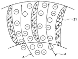
- FIG. 2 is a II-II sectional view showing a part of the fan of FIG. 1.
- FIG. 3 is a III-III cross-sectional view showing a part of the fan and casing of FIG. 1. It is sectional drawing of the principal part which shows the modification of the air blower which concerns on one Embodiment. It is a schematic diagram which shows the air blower which concerns on other embodiment.
- blower of this embodiment is applied to a vehicle air conditioner.
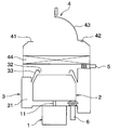
- the blower includes an electric motor 1 having a rotating shaft 11 and a resin fan 2 that is rotationally driven by the electric motor 1 to generate an air flow.
- the blower further includes a resin casing 3 that houses the fan 2 and has a spiral channel 31 that collects air blown from the fan 2.
- the blower further includes an inside / outside air switching unit 4 that selects air to be introduced into the fan 2, a first electrostatic charging device 5 that generates static electricity, and a second electrostatic charging device 6 that generates static electricity.
- the inside / outside air switching unit 4 includes an inside / outside air switching door 43 that selectively opens and closes an inside air introduction port 41 for introducing vehicle interior air and an outside air introduction port 42 for introducing outside air.
- the inside / outside air switching unit 4 includes a filter 44 that collects dust in the introduced air.
- a circular suction port 32 is formed coaxially with the rotary shaft 11.
- a bell mouth 33 for guiding the intake air to the suction port 32 is formed on the outer periphery of the suction port 32.
- the fan 2 is provided with a large number of plate-like blades 21 around the rotating shaft 11.
- the blade 21 is connected to the end portion on the suction port 32 side by an annular side plate 22.
- the end of the blade 21 on the side opposite to the suction port is connected by an annular main plate 23.
- the main plate 23 is coupled to the rotating shaft 11 at the center thereof.
- the driving force of the electric motor 1 is transmitted to the main plate 23 via the rotating shaft 11 so that the fan 2 is driven to rotate.
- the fan 2 is rotationally driven by the electric motor 1 to suck air into the fan 2 from the suction port 32 located on one end side in the fan rotation axis direction, and the sucked air is outside the fan radial direction. It comes to blow out towards. That is, the fan 2 is a centrifugal multiblade fan.
- the first electrostatic charging device 5 is fixed to the case of the inside / outside air switching unit 4 and generates static electricity having a negative polarity (that is, ⁇ ). As shown in FIG. 1, the first electrostatic charging device 5 is disposed between the inside / outside air switching door 43 and the suction port 32. More specifically, the first electrostatic charging device 5 is disposed between the inside / outside air switching door 43 and the filter 44 as shown in FIG. The first electrostatic charging device 5 discharges static electricity to the downstream side of the air flow from the inside air introduction port 41 and the outside air introduction port 42 and to the upstream side of the air flow from the filter 44 in the case of the inside / outside air switching unit 4. The negative charge is charged to the air sucked into the air. By charging the air with a negative charge, air sterilization and cleaning effects can be expected.
- ⁇ negative polarity
- the second electrostatic charging device 6 is fixed to the side opposite to the suction port in the casing 3 and is disposed to face the blade 21.
- the second electrostatic charging device 6 generates static electricity having a positive polarity (that is, +), discharges the generated static electricity into the casing 3, and charges the blade 21, the side plate 22, and the main plate 23 of the fan 2 with positive charges.
- the first electrostatic charging device 5 and the second electrostatic charging device 6 charge the air sucked into the fan 2 and the electric charges of different polarities to the fan 2.
- the material of the fan 2 may be a resin such as polypropylene or nylon.
- nylon When nylon is employed, there is an advantage that positive charges are easily charged.
- resin containing glass fiber when employed, there is an advantage that positive charges are easily charged.
- Polypropylene is also represented as PP.
- the electric motor 1 rotates the fan 2 to generate an air flow, and the first electrostatic charging device 5 and the second electrostatic charging device 6 generate static electricity. Then, the air flow A charged with a negative charge passes between the adjacent blades 21, more specifically, in the space surrounded by the blades 21, the side plates 22 and the main plate 23.
- the first electrostatic charging device 5 and the second electrostatic charging device 6 charge the air sucked into the fan 2 and the electric charges of different polarities with respect to the fan 2. Therefore, the air sucked into the fan 2 is attracted to the blade 21, the side plate 22, and the main plate 23 by the Coulomb force, and the separation of the air flow is suppressed.
- the resin fan 2 is used.
- the surface of the resin fan 2 is made of a coating layer 7 made of a substance that easily charges positive charges. May be provided.
- the material of the coating layer 7, for example, mica, that is, mica can be adopted.
- the present disclosure is applied to the blower of the vehicle air conditioner.
- the present disclosure can be applied to a blower for uses other than the vehicle air conditioner.
- centrifugal multiblade fan is shown as the fan 2, but the present disclosure can be applied to a fan 2 other than the centrifugal multiblade fan.
- the first electrostatic charging device 5 and the second electrostatic charging device 6 charge the air sucked into the fan 2 with a negative charge, and charge the fan 2 with a positive charge.
- the first electrostatic charging device 5 and the second electrostatic charging device 6 may charge the air sucked into the fan 2 with a positive charge and charge the fan 2 with a negative charge.
- the first electrostatic charging device 5 is disposed between the inside / outside air switching door 43 and the filter 44.
- the first electrostatic charging device 5 may be disposed between the filter 44 and the suction port 32.
- the first electrostatic charging device 5 discharges static electricity to the downstream side of the air flow from the filter 44 and the upstream side of the air flow from the suction port 32, and charges the air sucked into the fan 2 with a negative charge. By doing so, the charge amount of the filter 44 can be reduced.
- the blower is configured to rotate the fan to generate an air flow and to charge the air and the fan sucked into the fan with different polar charges. Device.
- the electrostatic charging device charges the air sucked into the fan with a negative charge and charges the fan with a positive charge. According to this, sterilization and cleaning effects of air can be expected.
- the fan is made of polypropylene. According to this, positive charges are easily charged, and separation of the air flow is more reliably suppressed.
- the fan is made of a resin containing glass fiber. According to this, positive charges are easily charged, and separation of the air flow is more reliably suppressed.
- the surface of the fan has a coating layer made of a substance that makes it easy to charge positive charges. According to this, positive charges are easily charged, and separation of the air flow is more reliably suppressed.
- the electrostatic charging device is disposed between an inside / outside air switching door for selecting air to be introduced into the fan and an inlet of the fan.
- the electrostatic charging device includes a device that charges one of the air sucked into the fan and the fan with a negative charge, and the air sucked into the fan and the other of the fan. And a device for charging a positive charge.
- the device that charges the negative charge and the device that charges the positive charge are arranged at different positions.
Landscapes
- Engineering & Computer Science (AREA)
- Mechanical Engineering (AREA)
- General Engineering & Computer Science (AREA)
- Structures Of Non-Positive Displacement Pumps (AREA)
- Air-Conditioning For Vehicles (AREA)
Abstract
送風機は、回転して空気流を発生させるファン(2)と、前記ファンに吸入される空気および前記ファンに対して、異なる極性の電荷を帯電させる静電気帯電装置(5、6)とを備える。
Description
本出願は、2016年3月31日に出願された日本特許出願番号2016-70721に基づくもので、ここにその記載内容が参照により組み入れられる。
本開示は、空気流を発生させる送風機に関するものである。
従来、この種の送風機として、例えば特許文献1に記載されたものがある。この特許文献1に記載された送風機は、遠心式多翼ファンであり、ブレードの前縁を曲率半径が小さい急峻な角形状に形成することにより、前縁での空気流れの剥離を抑制するものである。
しかしながら、従来の送風機は、ブレードの前縁での剥離領域の縮小効果はあるものの剥離領域は依然存在しており、ファン効率の向上や低騒音化への障害となっている。また、側板での空気流れの剥離も発生しており、これもファン効率の向上や低騒音化への障害となっている。
本開示は、ファン効率の向上および騒音の低減を図ることを目的とする。
本開示の1つの観点によれば、送風機は、回転して空気流を発生させるファンと、ファンに吸入される空気およびファンに対して、異なる極性の電荷を帯電させる静電気帯電装置とを備える。
これによると、ファンに吸入される空気はクーロン力によりファンに引き寄せられて空気流れの剥離が抑制されるため、ファン効率の向上および騒音の低減を図ることができる。
以下、本開示の実施形態について図面を参照して説明する。本実施形態の送風機は、車両用空調装置に適用される。
図1~図3に示すように、送風機は、回転軸11を有する電動モータ1と、この電動モータ1により回転駆動されて空気流を発生させる樹脂製のファン2とを備える。送風機は更に、このファン2を収納するとともに、ファン2から吹き出す空気を集合させる渦巻き状の流路31を有する樹脂製のケーシング3を備える。送風機は更に、ファン2に導入する空気を選択する内外気切換ユニット4と、静電気を発生させる第1静電気帯電装置5と、静電気を発生させる第2静電気帯電装置6とを備えている。
内外気切換ユニット4は、車室内気を導入するための内気導入口41と外気を導入するための外気導入口42を選択的に開閉する内外気切換ドア43を備えている。また、内外気切換ユニット4は、導入空気中の埃を捕集するフィルタ44を備えている。
ケーシング3には、回転軸11と同軸上に円形の吸入口32が形成されている。この吸入口32の外周部には、吸入空気を吸入口32に導くベルマウス33が形成されている。
ファン2は、回転軸11の周りに板状のブレード21が多数枚配設されている。このブレード21は、吸入口32側の端部が環状の側板22によって連結されている。また、ブレード21は、反吸入口側の端部が環状の主板23によって連結されている。
主板23は、その中心部において回転軸11に結合されている。電動モータ1の駆動力が回転軸11を介して主板23に伝達されることにより、ファン2が回転駆動される。そして、ファン2は、電動モータ1によって回転駆動されることにより、ファン回転軸方向の一端側に位置する吸入口32からファン2内に空気を吸引し、その吸入した空気をファン径方向の外側に向かって吹き出すようになっている。すなわち、ファン2は、遠心式多翼ファンである。
第1静電気帯電装置5は、内外気切換ユニット4のケースに固定され、極性が負(すなわち-)の静電気を発生する。第1静電気帯電装置5は、図1に示すように、内外気切換ドア43と吸入口32との間に配置される。より詳しくは、第1静電気帯電装置5は、図1に示すように、内外気切換ドア43とフィルタ44との間に配置される。第1静電気帯電装置5は、内外気切換ユニット4のケース内における内気導入口41および外気導入口42よりも空気流れ下流側で且つフィルタ44よりも空気流れ上流側に静電気を放出し、ファン2に吸入される空気に負電荷を帯電させる。空気に負電荷を帯電させることにより、空気の除菌や清浄効果が期待できる。
第2静電気帯電装置6は、ケーシング3における反吸入口側に固定され、ブレード21に対向して配置されている。第2静電気帯電装置6は、極性が正(すなわち+)の静電気を発生し、発生させた静電気をケーシング3内に放出し、ファン2のブレード21と側板22と主板23に正電荷を帯電させる。換言すると、第1静電気帯電装置5および第2静電気帯電装置6は、ファン2に吸入される空気およびファン2に対して、異なる極性の電荷を帯電させる。
なお、ファン2の材質は、ポリプロピレンやナイロン等の樹脂を採用することができる。ナイロンを採用した場合、正電荷が帯電しやすいという利点がある。また、ガラス繊維入りの樹脂を採用した場合も、正電荷が帯電しやすいという利点がある。ポリプロピレンはPPとも表される。
上記構成において、電動モータ1がファン2を回転させて空気流を発生させ、第1静電気帯電装置5および第2静電気帯電装置6に静電気を発生させる。すると、隣接するブレード21間を、より詳細には、ブレード21と側板22と主板23で囲まれた空間を、負電荷を帯電した空気の流れAが通過する。
ここで、第1静電気帯電装置5および第2静電気帯電装置6は、ファン2に吸入される空気およびファン2に対して、異なる極性の電荷を帯電させている。したがって、ファン2に吸入される空気はクーロン力によりブレード21と側板22と主板23に引き寄せられて空気流れの剥離が抑制される。
したがって、本実施形態によると、空気流れの剥離が抑制されるため、ファン効率の向上および騒音の低減を図ることができる。
なお、上記実施形態においては、樹脂製のファン2を用いたが、図4に示す変形例のように、樹脂製のファン2の表面に、正電荷を帯電させやすくする物質よりなるコーティング層7を設けてもよい。この場合、コーティング層7の物質は、例えば雲母、すなわちマイカ、を採用することができる。
(他の実施形態)
なお、上記実施形態では、本開示を車両用空調装置の送風機に適用したが、本開示は車両用空調装置以外の用途の送風機にも適用することができる。
なお、上記実施形態では、本開示を車両用空調装置の送風機に適用したが、本開示は車両用空調装置以外の用途の送風機にも適用することができる。
また、上記実施形態では、ファン2として遠心式多翼ファンを示したが、本開示は遠心式多翼ファン以外のファン2にも適用することができる。
また、上記実施形態では、第1静電気帯電装置5および第2静電気帯電装置6は、ファン2に吸入される空気に負電荷を帯電させ、ファン2に正電荷を帯電させた。しかし、第1静電気帯電装置5および第2静電気帯電装置6は、ファン2に吸入される空気に正電荷を帯電させ、ファン2に負電荷を帯電させてもよい。
また、上記実施形態では、第1静電気帯電装置5は、内外気切換ドア43とフィルタ44との間に配置される。しかし、第1静電気帯電装置5は、フィルタ44と吸入口32との間に配置されてもよい。この場合、第1静電気帯電装置5は、フィルタ44よりも空気流れ下流側で且つ吸入口32よりも空気流れ上流側に静電気を放出し、ファン2に吸入される空気に負電荷を帯電させる。このようにすることで、フィルタ44の帯電量を低減することができる。
また、本開示は上記した実施形態に限定されるものではなく、適宜変更が可能である。
また、上記実施形態において、実施形態を構成する要素は、特に必須であると明示した場合および原理的に明らかに必須であると考えられる場合等を除き、必ずしも必須のものではないことは言うまでもない。
また、上記実施形態において、実施形態の構成要素の個数、数値、量、範囲等の数値が言及されている場合、特に必須であると明示した場合および原理的に明らかに特定の数に限定される場合等を除き、その特定の数に限定されるものではない。
また、上記実施形態において、構成要素等の形状、位置関係等に言及するときは、特に明示した場合および原理的に特定の形状、位置関係等に限定される場合等を除き、その形状、位置関係等に限定されるものではない。
(まとめ)
上記実施形態で示された第1の観点によれば、送風機は、回転して空気流を発生させるファンと、ファンに吸入される空気およびファンに対して、異なる極性の電荷を帯電させる静電気帯電装置とを備える。
上記実施形態で示された第1の観点によれば、送風機は、回転して空気流を発生させるファンと、ファンに吸入される空気およびファンに対して、異なる極性の電荷を帯電させる静電気帯電装置とを備える。
また、第2の観点によれば、静電気帯電装置は、ファンに吸入される空気に負電荷を帯電させ、ファンに正電荷を帯電させる。これによると、空気の除菌や清浄効果が期待できる。
また、第3の観点によれば、ファンはポリプロピレンよりなる。これによると、正電荷が帯電しやすくなり、空気流れの剥離が一層確実に抑制される。
また、第4の観点によれば、ファンは、ガラス繊維入りの樹脂よりなる。これによると、正電荷が帯電しやすくなり、空気流れの剥離が一層確実に抑制される。
また、第5の観点によれば、ファンの表面に、正電荷を帯電させやすくする物質よりなるコーティング層を有する。これによると、正電荷が帯電しやすくなり、空気流れの剥離が一層確実に抑制される。
また、第6の観点によれば、前記静電気帯電装置は、前記ファンに導入する空気を選択する内外気切換ドアと、前記ファンの吸入口との間に配置される。
また、第7の観点によれば、前記静電気帯電装置は、前記ファンに吸入される空気および前記ファンの一方に負電荷を帯電させる装置と、前記ファンに吸入される空気および前記ファンの他方に正電荷を帯電させる装置とを有する。そして、前記負電荷を帯電させる装置と前記正電荷を帯電させる装置は、異なる位置に配置されている。
Claims (7)
- 回転して空気流を発生させるファン(2)と、
前記ファンに吸入される空気および前記ファンに対して、異なる極性の電荷を帯電させる静電気帯電装置(5、6)とを備える送風機。 - 前記静電気帯電装置は、前記ファンに吸入される空気に負電荷を帯電させ、前記ファンに正電荷を帯電させる請求項1に記載の送風機。
- 前記ファンはポリプロピレンよりなる請求項2に記載の送風機。
- 前記ファンは、ガラス繊維入りの樹脂よりなる請求項2または3に記載の送風機。
- 前記ファンの表面に、正電荷を帯電させやすくする物質よりなるコーティング層(7)を有する請求項2ないし4のいずれか1つに記載の送風機。
- 前記静電気帯電装置は、前記ファンに導入する空気を選択する内外気切換ドア(43)と、前記ファンの吸入口(32)との間に配置される請求項1ないし5のいずれか1つに記載の送風機。
- 前記静電気帯電装置は、前記ファンに吸入される空気および前記ファンの一方に負電荷を帯電させる装置(5)と、前記ファンに吸入される空気および前記ファンの他方に正電荷を帯電させる装置(6)とを有し、
前記負電荷を帯電させる装置と前記正電荷を帯電させる装置は、異なる位置に配置されている請求項1ないし6のいずれか1つに記載の送風機。
Priority Applications (1)
| Application Number | Priority Date | Filing Date | Title |
|---|---|---|---|
| JP2018509022A JP6489284B2 (ja) | 2016-03-31 | 2017-03-16 | 送風機 |
Applications Claiming Priority (2)
| Application Number | Priority Date | Filing Date | Title |
|---|---|---|---|
| JP2016-070721 | 2016-03-31 | ||
| JP2016070721 | 2016-03-31 |
Publications (1)
| Publication Number | Publication Date |
|---|---|
| WO2017169859A1 true WO2017169859A1 (ja) | 2017-10-05 |
Family
ID=59965348
Family Applications (1)
| Application Number | Title | Priority Date | Filing Date |
|---|---|---|---|
| PCT/JP2017/010758 Ceased WO2017169859A1 (ja) | 2016-03-31 | 2017-03-16 | 送風機 |
Country Status (2)
| Country | Link |
|---|---|
| JP (1) | JP6489284B2 (ja) |
| WO (1) | WO2017169859A1 (ja) |
Cited By (1)
| Publication number | Priority date | Publication date | Assignee | Title |
|---|---|---|---|---|
| JP2021085402A (ja) * | 2019-11-29 | 2021-06-03 | 株式会社Soken | 送風装置 |
Citations (3)
| Publication number | Priority date | Publication date | Assignee | Title |
|---|---|---|---|---|
| JP2002213391A (ja) * | 2001-01-15 | 2002-07-31 | Matsushita Seiko Co Ltd | 遠心送風羽根車 |
| JP2013245580A (ja) * | 2012-05-24 | 2013-12-09 | Sharp Corp | 送風装置 |
| JP2015175279A (ja) * | 2014-03-14 | 2015-10-05 | 株式会社デンソー | 遠心式多翼送風機 |
Family Cites Families (1)
| Publication number | Priority date | Publication date | Assignee | Title |
|---|---|---|---|---|
| JP2011168195A (ja) * | 2010-02-19 | 2011-09-01 | Denso Corp | 車両用空気浄化装置 |
-
2017
- 2017-03-16 WO PCT/JP2017/010758 patent/WO2017169859A1/ja not_active Ceased
- 2017-03-16 JP JP2018509022A patent/JP6489284B2/ja not_active Expired - Fee Related
Patent Citations (3)
| Publication number | Priority date | Publication date | Assignee | Title |
|---|---|---|---|---|
| JP2002213391A (ja) * | 2001-01-15 | 2002-07-31 | Matsushita Seiko Co Ltd | 遠心送風羽根車 |
| JP2013245580A (ja) * | 2012-05-24 | 2013-12-09 | Sharp Corp | 送風装置 |
| JP2015175279A (ja) * | 2014-03-14 | 2015-10-05 | 株式会社デンソー | 遠心式多翼送風機 |
Cited By (1)
| Publication number | Priority date | Publication date | Assignee | Title |
|---|---|---|---|---|
| JP2021085402A (ja) * | 2019-11-29 | 2021-06-03 | 株式会社Soken | 送風装置 |
Also Published As
| Publication number | Publication date |
|---|---|
| JPWO2017169859A1 (ja) | 2018-06-14 |
| JP6489284B2 (ja) | 2019-03-27 |
Similar Documents
| Publication | Publication Date | Title |
|---|---|---|
| CN105358841B (zh) | 送风机 | |
| US10641282B2 (en) | Fan device and vacuum cleaner including the same | |
| CN102317633B (zh) | 多叶片鼓风机 | |
| JP6303654B2 (ja) | 遠心式多翼送風機 | |
| US20180180050A1 (en) | Fan device and vacuum cleaner including the same | |
| CN106460867B (zh) | 离心式送风机及电动吸尘器 | |
| JP6489284B2 (ja) | 送風機 | |
| WO2015025498A1 (ja) | 送風機 | |
| CN113167295B (zh) | 离心风扇、离心送风机 | |
| JP2016094932A (ja) | タービン | |
| WO2017122406A1 (ja) | 遠心送風機 | |
| CN110494654B (zh) | 远心风扇、成型用模具及流体输送装置 | |
| CN113056613B (zh) | 离心式送风机 | |
| CN113056614B (zh) | 离心式送风机 | |
| CN113439163A (zh) | 离心送风机及使用离心送风机的空调机 | |
| JP2002005091A (ja) | 多翼ファン | |
| JP2019103355A (ja) | モータ、及び、それを有する送風装置 | |
| JPWO2018235221A1 (ja) | 電動送風機、電気掃除機、及び手乾燥装置 | |
| CN114761693A (zh) | 离心送风机 | |
| JP2016070075A (ja) | 遠心送風機 | |
| WO2018066232A1 (ja) | 遠心送風機 | |
| WO2021106406A1 (ja) | 送風機 | |
| CN112752908A (zh) | 具有双旋转翼的空气循环器 | |
| JPS62113893A (ja) | 遠心型送風機 | |
| CN108499238A (zh) | 分离装置 |
Legal Events
| Date | Code | Title | Description |
|---|---|---|---|
| ENP | Entry into the national phase |
Ref document number: 2018509022 Country of ref document: JP Kind code of ref document: A |
|
| NENP | Non-entry into the national phase |
Ref country code: DE |
|
| 121 | Ep: the epo has been informed by wipo that ep was designated in this application |
Ref document number: 17774403 Country of ref document: EP Kind code of ref document: A1 |
|
| 122 | Ep: pct application non-entry in european phase |
Ref document number: 17774403 Country of ref document: EP Kind code of ref document: A1 |