WO2017169591A1 - 多孔質支持体、多孔質支持体の製造方法、分離膜構造体及び分離膜構造体の製造方法 - Google Patents
多孔質支持体、多孔質支持体の製造方法、分離膜構造体及び分離膜構造体の製造方法 Download PDFInfo
- Publication number
- WO2017169591A1 WO2017169591A1 PCT/JP2017/009234 JP2017009234W WO2017169591A1 WO 2017169591 A1 WO2017169591 A1 WO 2017169591A1 JP 2017009234 W JP2017009234 W JP 2017009234W WO 2017169591 A1 WO2017169591 A1 WO 2017169591A1
- Authority
- WO
- WIPO (PCT)
- Prior art keywords
- layer
- outermost layer
- separation membrane
- support
- porosity
- Prior art date
Links
- 239000012528 membrane Substances 0.000 title claims description 96
- 238000000926 separation method Methods 0.000 title claims description 84
- 238000004519 manufacturing process Methods 0.000 title claims description 19
- 238000000034 method Methods 0.000 title description 16
- 238000010304 firing Methods 0.000 claims description 42
- 239000000758 substrate Substances 0.000 claims description 27
- 239000002131 composite material Substances 0.000 claims description 15
- 239000000463 material Substances 0.000 abstract description 34
- 239000010410 layer Substances 0.000 description 241
- 239000002245 particle Substances 0.000 description 50
- 239000011148 porous material Substances 0.000 description 34
- 239000002002 slurry Substances 0.000 description 20
- VYPSYNLAJGMNEJ-UHFFFAOYSA-N Silicium dioxide Chemical compound O=[Si]=O VYPSYNLAJGMNEJ-UHFFFAOYSA-N 0.000 description 18
- 239000011230 binding agent Substances 0.000 description 16
- 239000000470 constituent Substances 0.000 description 12
- 229910021536 Zeolite Inorganic materials 0.000 description 11
- HNPSIPDUKPIQMN-UHFFFAOYSA-N dioxosilane;oxo(oxoalumanyloxy)alumane Chemical compound O=[Si]=O.O=[Al]O[Al]=O HNPSIPDUKPIQMN-UHFFFAOYSA-N 0.000 description 11
- 239000000843 powder Substances 0.000 description 11
- 239000010457 zeolite Substances 0.000 description 11
- 238000005259 measurement Methods 0.000 description 10
- 239000000243 solution Substances 0.000 description 10
- XLYOFNOQVPJJNP-UHFFFAOYSA-N water Substances O XLYOFNOQVPJJNP-UHFFFAOYSA-N 0.000 description 10
- 239000013078 crystal Substances 0.000 description 9
- 229910010293 ceramic material Inorganic materials 0.000 description 8
- 239000000377 silicon dioxide Substances 0.000 description 8
- PNEYBMLMFCGWSK-UHFFFAOYSA-N aluminium oxide Inorganic materials [O-2].[O-2].[O-2].[Al+3].[Al+3] PNEYBMLMFCGWSK-UHFFFAOYSA-N 0.000 description 7
- 239000002344 surface layer Substances 0.000 description 7
- OKTJSMMVPCPJKN-UHFFFAOYSA-N Carbon Chemical compound [C] OKTJSMMVPCPJKN-UHFFFAOYSA-N 0.000 description 6
- GWEVSGVZZGPLCZ-UHFFFAOYSA-N Titan oxide Chemical compound O=[Ti]=O GWEVSGVZZGPLCZ-UHFFFAOYSA-N 0.000 description 6
- 239000012298 atmosphere Substances 0.000 description 6
- 229910052799 carbon Inorganic materials 0.000 description 6
- 238000004891 communication Methods 0.000 description 6
- 239000012530 fluid Substances 0.000 description 6
- 239000011521 glass Substances 0.000 description 6
- 238000002156 mixing Methods 0.000 description 6
- 229910052878 cordierite Inorganic materials 0.000 description 5
- JSKIRARMQDRGJZ-UHFFFAOYSA-N dimagnesium dioxido-bis[(1-oxido-3-oxo-2,4,6,8,9-pentaoxa-1,3-disila-5,7-dialuminabicyclo[3.3.1]nonan-7-yl)oxy]silane Chemical compound [Mg++].[Mg++].[O-][Si]([O-])(O[Al]1O[Al]2O[Si](=O)O[Si]([O-])(O1)O2)O[Al]1O[Al]2O[Si](=O)O[Si]([O-])(O1)O2 JSKIRARMQDRGJZ-UHFFFAOYSA-N 0.000 description 5
- 239000002270 dispersing agent Substances 0.000 description 5
- 239000007789 gas Substances 0.000 description 5
- 239000002994 raw material Substances 0.000 description 5
- 239000002562 thickening agent Substances 0.000 description 5
- 238000012935 Averaging Methods 0.000 description 4
- CURLTUGMZLYLDI-UHFFFAOYSA-N Carbon dioxide Chemical compound O=C=O CURLTUGMZLYLDI-UHFFFAOYSA-N 0.000 description 4
- CPLXHLVBOLITMK-UHFFFAOYSA-N Magnesium oxide Chemical compound [Mg]=O CPLXHLVBOLITMK-UHFFFAOYSA-N 0.000 description 4
- 238000001914 filtration Methods 0.000 description 4
- 229910052751 metal Inorganic materials 0.000 description 4
- 239000002184 metal Substances 0.000 description 4
- 239000002243 precursor Substances 0.000 description 4
- 230000000630 rising effect Effects 0.000 description 4
- 238000005245 sintering Methods 0.000 description 4
- 239000004094 surface-active agent Substances 0.000 description 4
- DKNWSYNQZKUICI-UHFFFAOYSA-N amantadine Chemical compound C1C(C2)CC3CC2CC1(N)C3 DKNWSYNQZKUICI-UHFFFAOYSA-N 0.000 description 3
- 230000015572 biosynthetic process Effects 0.000 description 3
- 239000011248 coating agent Substances 0.000 description 3
- 238000000576 coating method Methods 0.000 description 3
- 238000001816 cooling Methods 0.000 description 3
- 238000000445 field-emission scanning electron microscopy Methods 0.000 description 3
- 238000010438 heat treatment Methods 0.000 description 3
- 239000003002 pH adjusting agent Substances 0.000 description 3
- 238000005192 partition Methods 0.000 description 3
- 230000002093 peripheral effect Effects 0.000 description 3
- 229910018072 Al 2 O 3 Inorganic materials 0.000 description 2
- LFQSCWFLJHTTHZ-UHFFFAOYSA-N Ethanol Chemical compound CCO LFQSCWFLJHTTHZ-UHFFFAOYSA-N 0.000 description 2
- PIICEJLVQHRZGT-UHFFFAOYSA-N Ethylenediamine Chemical compound NCCN PIICEJLVQHRZGT-UHFFFAOYSA-N 0.000 description 2
- KDLHZDBZIXYQEI-UHFFFAOYSA-N Palladium Chemical compound [Pd] KDLHZDBZIXYQEI-UHFFFAOYSA-N 0.000 description 2
- 239000001569 carbon dioxide Substances 0.000 description 2
- 229910002092 carbon dioxide Inorganic materials 0.000 description 2
- 239000000919 ceramic Substances 0.000 description 2
- 239000004927 clay Substances 0.000 description 2
- 239000008119 colloidal silica Substances 0.000 description 2
- KZHJGOXRZJKJNY-UHFFFAOYSA-N dioxosilane;oxo(oxoalumanyloxy)alumane Chemical compound O=[Si]=O.O=[Si]=O.O=[Al]O[Al]=O.O=[Al]O[Al]=O.O=[Al]O[Al]=O KZHJGOXRZJKJNY-UHFFFAOYSA-N 0.000 description 2
- 239000006185 dispersion Substances 0.000 description 2
- 229910010272 inorganic material Inorganic materials 0.000 description 2
- 239000011147 inorganic material Substances 0.000 description 2
- 239000007788 liquid Substances 0.000 description 2
- 239000000395 magnesium oxide Substances 0.000 description 2
- VNWKTOKETHGBQD-UHFFFAOYSA-N methane Chemical compound C VNWKTOKETHGBQD-UHFFFAOYSA-N 0.000 description 2
- 229910052863 mullite Inorganic materials 0.000 description 2
- 238000010899 nucleation Methods 0.000 description 2
- 229920001721 polyimide Polymers 0.000 description 2
- 239000009719 polyimide resin Substances 0.000 description 2
- 239000011347 resin Substances 0.000 description 2
- 229920005989 resin Polymers 0.000 description 2
- 238000007789 sealing Methods 0.000 description 2
- 239000007787 solid Substances 0.000 description 2
- 239000000126 substance Substances 0.000 description 2
- 238000003786 synthesis reaction Methods 0.000 description 2
- KXGFMDJXCMQABM-UHFFFAOYSA-N 2-methoxy-6-methylphenol Chemical compound [CH]OC1=CC=CC([CH])=C1O KXGFMDJXCMQABM-UHFFFAOYSA-N 0.000 description 1
- SUBDBMMJDZJVOS-UHFFFAOYSA-N 5-methoxy-2-{[(4-methoxy-3,5-dimethylpyridin-2-yl)methyl]sulfinyl}-1H-benzimidazole Chemical compound N=1C2=CC(OC)=CC=C2NC=1S(=O)CC1=NC=C(C)C(OC)=C1C SUBDBMMJDZJVOS-UHFFFAOYSA-N 0.000 description 1
- 238000007088 Archimedes method Methods 0.000 description 1
- ODINCKMPIJJUCX-UHFFFAOYSA-N Calcium oxide Chemical compound [Ca]=O ODINCKMPIJJUCX-UHFFFAOYSA-N 0.000 description 1
- UGFAIRIUMAVXCW-UHFFFAOYSA-N Carbon monoxide Chemical compound [O+]#[C-] UGFAIRIUMAVXCW-UHFFFAOYSA-N 0.000 description 1
- 229910004298 SiO 2 Inorganic materials 0.000 description 1
- BOTDANWDWHJENH-UHFFFAOYSA-N Tetraethyl orthosilicate Chemical compound CCO[Si](OCC)(OCC)OCC BOTDANWDWHJENH-UHFFFAOYSA-N 0.000 description 1
- 229910010413 TiO 2 Inorganic materials 0.000 description 1
- 239000012752 auxiliary agent Substances 0.000 description 1
- 230000005540 biological transmission Effects 0.000 description 1
- 239000000292 calcium oxide Substances 0.000 description 1
- 235000012255 calcium oxide Nutrition 0.000 description 1
- 229910002091 carbon monoxide Inorganic materials 0.000 description 1
- 238000005266 casting Methods 0.000 description 1
- 238000006555 catalytic reaction Methods 0.000 description 1
- 239000002734 clay mineral Substances 0.000 description 1
- 239000011362 coarse particle Substances 0.000 description 1
- 238000005260 corrosion Methods 0.000 description 1
- 230000007797 corrosion Effects 0.000 description 1
- 238000003618 dip coating Methods 0.000 description 1
- 239000003822 epoxy resin Substances 0.000 description 1
- 239000001307 helium Substances 0.000 description 1
- 229910052734 helium Inorganic materials 0.000 description 1
- SWQJXJOGLNCZEY-UHFFFAOYSA-N helium atom Chemical compound [He] SWQJXJOGLNCZEY-UHFFFAOYSA-N 0.000 description 1
- 239000001257 hydrogen Substances 0.000 description 1
- 229910052739 hydrogen Inorganic materials 0.000 description 1
- 125000004435 hydrogen atom Chemical class [H]* 0.000 description 1
- 238000001027 hydrothermal synthesis Methods 0.000 description 1
- NLYAJNPCOHFWQQ-UHFFFAOYSA-N kaolin Chemical compound O.O.O=[Al]O[Si](=O)O[Si](=O)O[Al]=O NLYAJNPCOHFWQQ-UHFFFAOYSA-N 0.000 description 1
- QSHDDOUJBYECFT-UHFFFAOYSA-N mercury Chemical compound [Hg] QSHDDOUJBYECFT-UHFFFAOYSA-N 0.000 description 1
- 229910052753 mercury Inorganic materials 0.000 description 1
- 239000007769 metal material Substances 0.000 description 1
- 239000011259 mixed solution Substances 0.000 description 1
- 239000003960 organic solvent Substances 0.000 description 1
- 230000001590 oxidative effect Effects 0.000 description 1
- 229910052763 palladium Inorganic materials 0.000 description 1
- 230000035515 penetration Effects 0.000 description 1
- 239000012466 permeate Substances 0.000 description 1
- 239000005011 phenolic resin Substances 0.000 description 1
- 229920001568 phenolic resin Polymers 0.000 description 1
- 238000005498 polishing Methods 0.000 description 1
- 229920000647 polyepoxide Polymers 0.000 description 1
- 238000002360 preparation method Methods 0.000 description 1
- 238000003825 pressing Methods 0.000 description 1
- 238000012545 processing Methods 0.000 description 1
- 238000004904 shortening Methods 0.000 description 1
- RMAQACBXLXPBSY-UHFFFAOYSA-N silicic acid Chemical compound O[Si](O)(O)O RMAQACBXLXPBSY-UHFFFAOYSA-N 0.000 description 1
- 238000000992 sputter etching Methods 0.000 description 1
- 238000004381 surface treatment Methods 0.000 description 1
Images


Classifications
-
- B—PERFORMING OPERATIONS; TRANSPORTING
- B01—PHYSICAL OR CHEMICAL PROCESSES OR APPARATUS IN GENERAL
- B01D—SEPARATION
- B01D69/00—Semi-permeable membranes for separation processes or apparatus characterised by their form, structure or properties; Manufacturing processes specially adapted therefor
- B01D69/10—Supported membranes; Membrane supports
-
- B—PERFORMING OPERATIONS; TRANSPORTING
- B01—PHYSICAL OR CHEMICAL PROCESSES OR APPARATUS IN GENERAL
- B01D—SEPARATION
- B01D53/00—Separation of gases or vapours; Recovering vapours of volatile solvents from gases; Chemical or biological purification of waste gases, e.g. engine exhaust gases, smoke, fumes, flue gases, aerosols
- B01D53/22—Separation of gases or vapours; Recovering vapours of volatile solvents from gases; Chemical or biological purification of waste gases, e.g. engine exhaust gases, smoke, fumes, flue gases, aerosols by diffusion
- B01D53/228—Separation of gases or vapours; Recovering vapours of volatile solvents from gases; Chemical or biological purification of waste gases, e.g. engine exhaust gases, smoke, fumes, flue gases, aerosols by diffusion characterised by specific membranes
-
- B—PERFORMING OPERATIONS; TRANSPORTING
- B01—PHYSICAL OR CHEMICAL PROCESSES OR APPARATUS IN GENERAL
- B01D—SEPARATION
- B01D67/00—Processes specially adapted for manufacturing semi-permeable membranes for separation processes or apparatus
- B01D67/0002—Organic membrane manufacture
- B01D67/0006—Organic membrane manufacture by chemical reactions
-
- B—PERFORMING OPERATIONS; TRANSPORTING
- B01—PHYSICAL OR CHEMICAL PROCESSES OR APPARATUS IN GENERAL
- B01D—SEPARATION
- B01D67/00—Processes specially adapted for manufacturing semi-permeable membranes for separation processes or apparatus
- B01D67/0039—Inorganic membrane manufacture
- B01D67/0041—Inorganic membrane manufacture by agglomeration of particles in the dry state
- B01D67/00411—Inorganic membrane manufacture by agglomeration of particles in the dry state by sintering
-
- B—PERFORMING OPERATIONS; TRANSPORTING
- B01—PHYSICAL OR CHEMICAL PROCESSES OR APPARATUS IN GENERAL
- B01D—SEPARATION
- B01D69/00—Semi-permeable membranes for separation processes or apparatus characterised by their form, structure or properties; Manufacturing processes specially adapted therefor
- B01D69/12—Composite membranes; Ultra-thin membranes
- B01D69/1216—Three or more layers
-
- B—PERFORMING OPERATIONS; TRANSPORTING
- B01—PHYSICAL OR CHEMICAL PROCESSES OR APPARATUS IN GENERAL
- B01D—SEPARATION
- B01D71/00—Semi-permeable membranes for separation processes or apparatus characterised by the material; Manufacturing processes specially adapted therefor
- B01D71/02—Inorganic material
- B01D71/024—Oxides
- B01D71/025—Aluminium oxide
-
- B—PERFORMING OPERATIONS; TRANSPORTING
- B01—PHYSICAL OR CHEMICAL PROCESSES OR APPARATUS IN GENERAL
- B01D—SEPARATION
- B01D71/00—Semi-permeable membranes for separation processes or apparatus characterised by the material; Manufacturing processes specially adapted therefor
- B01D71/02—Inorganic material
- B01D71/028—Molecular sieves
- B01D71/0281—Zeolites
-
- C—CHEMISTRY; METALLURGY
- C04—CEMENTS; CONCRETE; ARTIFICIAL STONE; CERAMICS; REFRACTORIES
- C04B—LIME, MAGNESIA; SLAG; CEMENTS; COMPOSITIONS THEREOF, e.g. MORTARS, CONCRETE OR LIKE BUILDING MATERIALS; ARTIFICIAL STONE; CERAMICS; REFRACTORIES; TREATMENT OF NATURAL STONE
- C04B38/00—Porous mortars, concrete, artificial stone or ceramic ware; Preparation thereof
- C04B38/0006—Honeycomb structures
-
- C—CHEMISTRY; METALLURGY
- C04—CEMENTS; CONCRETE; ARTIFICIAL STONE; CERAMICS; REFRACTORIES
- C04B—LIME, MAGNESIA; SLAG; CEMENTS; COMPOSITIONS THEREOF, e.g. MORTARS, CONCRETE OR LIKE BUILDING MATERIALS; ARTIFICIAL STONE; CERAMICS; REFRACTORIES; TREATMENT OF NATURAL STONE
- C04B41/00—After-treatment of mortars, concrete, artificial stone or ceramics; Treatment of natural stone
- C04B41/009—After-treatment of mortars, concrete, artificial stone or ceramics; Treatment of natural stone characterised by the material treated
-
- C—CHEMISTRY; METALLURGY
- C04—CEMENTS; CONCRETE; ARTIFICIAL STONE; CERAMICS; REFRACTORIES
- C04B—LIME, MAGNESIA; SLAG; CEMENTS; COMPOSITIONS THEREOF, e.g. MORTARS, CONCRETE OR LIKE BUILDING MATERIALS; ARTIFICIAL STONE; CERAMICS; REFRACTORIES; TREATMENT OF NATURAL STONE
- C04B41/00—After-treatment of mortars, concrete, artificial stone or ceramics; Treatment of natural stone
- C04B41/45—Coating or impregnating, e.g. injection in masonry, partial coating of green or fired ceramics, organic coating compositions for adhering together two concrete elements
- C04B41/52—Multiple coating or impregnating multiple coating or impregnating with the same composition or with compositions only differing in the concentration of the constituents, is classified as single coating or impregnation
-
- C—CHEMISTRY; METALLURGY
- C04—CEMENTS; CONCRETE; ARTIFICIAL STONE; CERAMICS; REFRACTORIES
- C04B—LIME, MAGNESIA; SLAG; CEMENTS; COMPOSITIONS THEREOF, e.g. MORTARS, CONCRETE OR LIKE BUILDING MATERIALS; ARTIFICIAL STONE; CERAMICS; REFRACTORIES; TREATMENT OF NATURAL STONE
- C04B41/00—After-treatment of mortars, concrete, artificial stone or ceramics; Treatment of natural stone
- C04B41/80—After-treatment of mortars, concrete, artificial stone or ceramics; Treatment of natural stone of only ceramics
- C04B41/81—Coating or impregnation
- C04B41/85—Coating or impregnation with inorganic materials
-
- C—CHEMISTRY; METALLURGY
- C04—CEMENTS; CONCRETE; ARTIFICIAL STONE; CERAMICS; REFRACTORIES
- C04B—LIME, MAGNESIA; SLAG; CEMENTS; COMPOSITIONS THEREOF, e.g. MORTARS, CONCRETE OR LIKE BUILDING MATERIALS; ARTIFICIAL STONE; CERAMICS; REFRACTORIES; TREATMENT OF NATURAL STONE
- C04B41/00—After-treatment of mortars, concrete, artificial stone or ceramics; Treatment of natural stone
- C04B41/80—After-treatment of mortars, concrete, artificial stone or ceramics; Treatment of natural stone of only ceramics
- C04B41/81—Coating or impregnation
- C04B41/89—Coating or impregnation for obtaining at least two superposed coatings having different compositions
-
- B—PERFORMING OPERATIONS; TRANSPORTING
- B01—PHYSICAL OR CHEMICAL PROCESSES OR APPARATUS IN GENERAL
- B01D—SEPARATION
- B01D2256/00—Main component in the product gas stream after treatment
- B01D2256/24—Hydrocarbons
- B01D2256/245—Methane
-
- B—PERFORMING OPERATIONS; TRANSPORTING
- B01—PHYSICAL OR CHEMICAL PROCESSES OR APPARATUS IN GENERAL
- B01D—SEPARATION
- B01D2257/00—Components to be removed
- B01D2257/50—Carbon oxides
- B01D2257/504—Carbon dioxide
-
- B—PERFORMING OPERATIONS; TRANSPORTING
- B01—PHYSICAL OR CHEMICAL PROCESSES OR APPARATUS IN GENERAL
- B01D—SEPARATION
- B01D2325/00—Details relating to properties of membranes
- B01D2325/02—Details relating to pores or porosity of the membranes
-
- B—PERFORMING OPERATIONS; TRANSPORTING
- B01—PHYSICAL OR CHEMICAL PROCESSES OR APPARATUS IN GENERAL
- B01D—SEPARATION
- B01D2325/00—Details relating to properties of membranes
- B01D2325/02—Details relating to pores or porosity of the membranes
- B01D2325/0283—Pore size
-
- B—PERFORMING OPERATIONS; TRANSPORTING
- B01—PHYSICAL OR CHEMICAL PROCESSES OR APPARATUS IN GENERAL
- B01D—SEPARATION
- B01D2325/00—Details relating to properties of membranes
- B01D2325/04—Characteristic thickness
-
- B—PERFORMING OPERATIONS; TRANSPORTING
- B01—PHYSICAL OR CHEMICAL PROCESSES OR APPARATUS IN GENERAL
- B01D—SEPARATION
- B01D69/00—Semi-permeable membranes for separation processes or apparatus characterised by their form, structure or properties; Manufacturing processes specially adapted therefor
- B01D69/04—Tubular membranes
-
- B—PERFORMING OPERATIONS; TRANSPORTING
- B01—PHYSICAL OR CHEMICAL PROCESSES OR APPARATUS IN GENERAL
- B01D—SEPARATION
- B01D69/00—Semi-permeable membranes for separation processes or apparatus characterised by their form, structure or properties; Manufacturing processes specially adapted therefor
- B01D69/08—Hollow fibre membranes
-
- C—CHEMISTRY; METALLURGY
- C04—CEMENTS; CONCRETE; ARTIFICIAL STONE; CERAMICS; REFRACTORIES
- C04B—LIME, MAGNESIA; SLAG; CEMENTS; COMPOSITIONS THEREOF, e.g. MORTARS, CONCRETE OR LIKE BUILDING MATERIALS; ARTIFICIAL STONE; CERAMICS; REFRACTORIES; TREATMENT OF NATURAL STONE
- C04B2111/00—Mortars, concrete or artificial stone or mixtures to prepare them, characterised by specific function, property or use
- C04B2111/00474—Uses not provided for elsewhere in C04B2111/00
- C04B2111/00793—Uses not provided for elsewhere in C04B2111/00 as filters or diaphragms
- C04B2111/00801—Membranes; Diaphragms
-
- Y—GENERAL TAGGING OF NEW TECHNOLOGICAL DEVELOPMENTS; GENERAL TAGGING OF CROSS-SECTIONAL TECHNOLOGIES SPANNING OVER SEVERAL SECTIONS OF THE IPC; TECHNICAL SUBJECTS COVERED BY FORMER USPC CROSS-REFERENCE ART COLLECTIONS [XRACs] AND DIGESTS
- Y02—TECHNOLOGIES OR APPLICATIONS FOR MITIGATION OR ADAPTATION AGAINST CLIMATE CHANGE
- Y02C—CAPTURE, STORAGE, SEQUESTRATION OR DISPOSAL OF GREENHOUSE GASES [GHG]
- Y02C20/00—Capture or disposal of greenhouse gases
- Y02C20/40—Capture or disposal of greenhouse gases of CO2
Definitions
- the present invention relates to a porous support, a method for producing a porous support, a separation membrane structure, and a method for producing a separation membrane structure.
- a separation membrane structure comprising a base material, an intermediate layer formed on the base material and a surface layer formed on the intermediate layer, and a separation membrane formed on the surface layer. It is known (see Patent Document 1).
- the average pore diameter of the intermediate layer is smaller than the average pore diameter of the substrate, and the average pore diameter of the surface layer is the average pore diameter of the intermediate layer Has been smaller than.
- the present invention has been made to solve the above-mentioned problems, and is capable of improving the permeation amount of the separation membrane while maintaining the strength, the method for producing the porous support, the separation membrane structure, and the It aims at providing the manufacturing method of a separation membrane structure.
- the porous support according to the present invention includes a base material, a support layer, and an outermost layer.
- the support layer is disposed between the base material and the outermost layer and is in contact with the outermost layer.
- the ratio of the porosity of the outermost layer to the porosity of the support layer is 1.08 or more.
- the ratio of the thickness of the outermost layer to the thickness of the support layer is 0.9 or less.
- a porous support capable of improving the permeation amount of the separation membrane, a method for producing the porous support, a separation membrane structure, and a method for producing the separation membrane structure can be provided.
- the “monolith” means a shape having a plurality of communication holes formed in the longitudinal direction, and is a concept including a honeycomb shape.
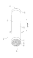
- FIG. 1 is a perspective view of the separation membrane structure 10.
- FIG. 2 is a cross-sectional view taken along the line AA in FIG.
- the separation membrane structure 10 includes a porous support 20, a first seal portion 21, a second seal portion 22, and a separation membrane 23.
- the porous support 20 is a monolithic porous body.
- the length of the porous support 20 is not particularly limited, but may be, for example, 150 mm to 2000 mm.
- the diameter of the porous support 20 is not particularly limited, but can be, for example, 30 mm to 220 mm.
- the outer shape of the porous support 20 is not limited to the monolith shape, and may be a flat plate shape, a tube shape, a cylindrical shape, a columnar shape, a prismatic shape, or the like.
- the porous support 20 has a first end surface S1, a second end surface S2, and a side surface S3.
- the first end surface S1 is provided opposite to the second end surface S2.
- the side surface S3 continues to the outer edges of the first end surface S1 and the second end surface S2.
- the porous support 20 has a plurality of communication holes TH that are continuous with the first end surface S1 and the second end surface S2.
- the plurality of communication holes TH extend in the longitudinal direction of the porous support 20.
- the first seal portion 21 covers substantially the entire first end surface S1 and a part of the side surface S3.
- the first seal portion 21 prevents the mixed fluid (liquid mixed fluid or gas mixed fluid) to be filtered from infiltrating the first end surface S ⁇ b> 1 of the porous support 20.
- a material constituting the first seal portion 21 glass, metal, or the like can be used, and glass is suitable in consideration of consistency with the thermal expansion coefficient of the porous support 20.
- the second seal portion 22 covers substantially the entire second end surface S2 and part of the side surface S3.
- the second seal portion 22 prevents the mixed fluid to be filtered from infiltrating the second end surface S ⁇ b> 2 of the porous support 20.
- glass, metal, or the like can be used, and glass is preferable in consideration of consistency with the thermal expansion coefficient of the porous support 20.
- the separation membrane 23 is formed on the inner surface of each of the plurality of communication holes TH formed in the porous support 20.
- the separation membrane 23 is formed in a cylindrical shape.
- the inside of the separation membrane 23 is a cell CL for flowing a mixed fluid to be filtered.
- the separation membrane structure 10 has a plurality of cells CL including a central cell CL1 and a plurality of outermost cells CL2. Note that the cross-sectional shape of the cell CL is not limited to a circle, and may be a polygon more than a triangle.
- an inorganic material, a metal, or the like can be used as a material constituting the separation membrane 23 as a material constituting the separation membrane 23.
- the inorganic material for the separation membrane 23 include zeolite, carbon, and silica.
- the crystal structure of the zeolite constituting the separation membrane 23 is not particularly limited, and for example, LTA, MFI, MOR, FER, FAU, DDR, CHA, BEA and the like can be used.
- the separation membrane 23 is a DDR type zeolite membrane, it can be suitably used as a gas separation membrane for selectively separating carbon dioxide.
- the metal material of the separation membrane 23 include palladium.
- the thickness of the separation membrane 23 in the radial direction around the central axis of the cell CL can be arbitrarily set depending on the material type constituting the separation membrane 23, but the permeation amount of the permeated component that can permeate the separation membrane 23 in the mixed fluid Is preferably 10 ⁇ m or less, more preferably 5 ⁇ m or less.
- (Configuration of porous support 20) 3 is a cross-sectional view taken along the line BB of FIG.
- the porous support 20 includes a base material 30, an intermediate layer 31, a support layer 32, and an outermost layer 33.
- the substrate 30 is made of a porous material.
- a porous material constituting the substrate 30, ceramics, metal, resin, and the like can be used, and a porous ceramic material is particularly preferable.
- aggregate particles of the porous ceramic material alumina (Al 2 O 3 ), titania (TiO 2 ), mullite (Al 2 O 3 .SiO 2 ), cerven and cordierite (Mg 2 Al 4 Si 5 O 18 ) In view of easy availability, stability of clay, and corrosion resistance, alumina is particularly preferable.
- the base material 30 may contain an inorganic binder in addition to the porous material.
- the inorganic binding material is a binding material for binding aggregate particles, and is an inorganic component that is sintered and solidified at a temperature at which the aggregate particles are not sintered.
- As the inorganic binder at least one of titania, magnesia, calcia, mullite, sinterable alumina, silica, glass frit, clay mineral, and sinterable cordierite can be used.
- the easily sinterable alumina can be used when the aggregate particles are alumina, and has an average particle size of 1/10 or less of the average particle size of the aggregate particles.
- the easily sinterable cordierite can be used when the aggregate particles are cordierite, and is cordierite having an average particle size of 1/10 or less of the average particle size of the aggregate particles.
- the porosity of the substrate 30 is not particularly limited, but can be 25% to 50%.
- the porosity of the substrate 30 is preferably 45% or less in consideration of the strength (for example, internal pressure fracture strength) of the porous support 20.
- the porosity of the substrate 30 can be measured by the Archimedes method.
- the average pore diameter of the substrate 30 is not particularly limited, but can be 5 ⁇ m to 25 ⁇ m.
- the average pore diameter of the base material 30 is preferably 10 ⁇ m or more in consideration of the permeation speed of the permeation component that has passed through the separation membrane 23 through the base material 30.
- the average pore diameter of the substrate 30 can be measured with a mercury porosimeter.
- the average particle diameter of the constituent particles of the substrate 30 is not limited, but can be 5 ⁇ m to 200 ⁇ m.
- the average particle size of the constituent particles of the substrate 30 is preferably 75 ⁇ m to 150 ⁇ m in consideration of the permeation resistance of the substrate 30.
- the average particle diameter of the constituent particles of the base material 30 is obtained by arithmetically averaging the maximum diameters of 30 measurement target particles measured by cross-sectional microstructure observation using a scanning electron microscope (SEM).
- the thickness of the base material 30 between the two cells CL (hereinafter referred to as “partition wall thickness”) is not particularly limited, but may be 0.5 mm to 2.0 mm.
- partition wall thickness By increasing the partition wall thickness, the strength (for example, internal pressure fracture strength) of the porous support 20 can be improved.
- partition wall thickness By reducing the partition wall thickness, the number of cells CL that can be formed on the porous support 20 can be increased, so that the permeation amount of the permeation component can be increased.
- the intermediate layer 31 is formed on the inner surface of the base material 30.
- the intermediate layer 31 is formed in a cylindrical shape.
- the intermediate layer 31 is made of a porous ceramic material. Examples of the porous ceramic material include those that can be used for the substrate 30 described above.
- the intermediate layer 31 may include an inorganic binder in addition to the porous material. As an inorganic binder, what can be used for the base material 30 mentioned above is mentioned.
- the porosity of the intermediate layer 31 is not particularly limited, but can be 5% to 60%. Considering the strength of the porous support 20, the porosity of the intermediate layer 31 is preferably 30% or less. The porosity of the intermediate layer 31 is preferably 31% or more in consideration of the permeation rate of the permeated component that has passed through the separation membrane 23 in the intermediate layer 31. The porosity of the intermediate layer 31 can be measured by calculation by binarizing an image acquired by FE-SEM observation.
- the thickness of the intermediate layer 31 is not particularly limited, but can be 50 ⁇ m to 500 ⁇ m, preferably 100 ⁇ m to 300 ⁇ m. By increasing the thickness of the intermediate layer 31, the strength of the porous support 20 can be improved. By reducing the thickness of the intermediate layer 31, the surface area of the separation membrane 23 in the cell CL can be increased, so that the permeation amount of the permeation component can be increased.
- the average pore diameter of the intermediate layer 31 is not particularly limited, but may be smaller than the average pore diameter of the substrate 30, and may be 0.05 ⁇ m to 5 ⁇ m, for example.
- the average pore diameter of the intermediate layer 31 is preferably 0.1 ⁇ m or more in consideration of the permeation speed of the permeated component that has passed through the separation membrane 23 in the intermediate layer 31.
- the average pore diameter of the intermediate layer 31 can be measured by an air flow method described in ASTM F316.
- the average particle diameter of the constituent particles of the intermediate layer 31 is not particularly limited, but may be 1 ⁇ m to 100 ⁇ m.
- the average particle diameter of the constituent particles of the intermediate layer 31 is preferably 20 ⁇ m to 50 ⁇ m in consideration of permeation resistance and strength.
- the average particle diameter of the constituent particles of the intermediate layer 31 is obtained by arithmetically averaging the maximum diameters of 30 measurement target particles measured by cross-sectional microstructure observation using an SEM.
- Support layer 32 The support layer 32 is formed on the inner surface of the intermediate layer 31.
- the support layer 32 is formed in a cylindrical shape.
- the support layer 32 supports the outermost layer 33 described later.
- the support layer 32 is made of a porous ceramic material. Examples of the porous ceramic material include those that can be used for the substrate 30 described above.
- the support layer 32 may contain an inorganic binder in addition to the porous material. As an inorganic binder, what can be used for the base material 30 mentioned above is mentioned.
- the porosity of the support layer 32 only needs to be lower than the porosity of the outermost layer 33 in order to ensure strength, and can be, for example, 5% to 50%.
- the porosity of the support layer 32 is preferably 42% or less, more preferably 35% or less, and particularly preferably 27% or less in consideration of the strength of the support layer 32 itself that supports the outermost layer 33.
- the porosity of the support layer 32 is preferably 12% or more, more preferably 27% or more, and particularly preferably 35% or more in consideration of the permeation rate of the permeable component that has passed through the separation membrane 23 in the support layer 32.
- the porosity of the support layer 32 can be calculated by binarizing an image acquired by SEM observation.
- the thickness of the support layer 32 is not particularly limited, but can be 1 ⁇ m to 300 ⁇ m, preferably 10 ⁇ m to 250 ⁇ m. By increasing the thickness of the support layer 32, the strength of the porous support 20 can be improved. By reducing the thickness of the support layer 32, the surface area of the separation membrane 23 in the cell CL can be increased, so that the permeation amount of the permeation component can be increased.
- the average pore diameter of the support layer 32 is not particularly limited, but may be smaller than the average pore diameter of the intermediate layer 31, and may be, for example, 0.001 ⁇ m to 1 ⁇ m.
- the average pore diameter of the support layer 32 is preferably 0.05 ⁇ m or more in consideration of the permeation speed of the permeable component that has passed through the separation membrane 23 in the support layer 32.
- the average pore diameter of the support layer 32 can be measured by an air flow method described in ASTM F316.
- the average particle size of the constituent particles of the support layer 32 is not particularly limited, but may be 0.01 ⁇ m to 1 ⁇ m.
- the average particle diameter of the constituent particles of the support layer 32 is preferably 0.05 ⁇ m to 0.8 ⁇ m in consideration of permeation resistance and strength.
- the average particle diameter of the constituent particles of the support layer 32 is obtained by arithmetically averaging the maximum diameters of 30 measurement target particles measured by cross-sectional microstructure observation using an SEM.
- Outermost layer 33 The outermost layer 33 is formed on the inner surface of the support layer 32.
- the outermost layer 33 is formed in a cylindrical shape.
- the outermost layer 33 is made of a porous ceramic material. Examples of the porous ceramic material include those that can be used for the substrate 30 described above.
- the outermost layer 33 may contain an inorganic binder in addition to the porous material. As an inorganic binder, what can be used for the base material 30 mentioned above is mentioned.
- the porosity of the outermost layer 33 is higher than the porosity of the support layer 32. Specifically, the ratio of the porosity of the outermost layer 33 to the porosity of the support layer 32 is 1.08 or more. As a result, a sufficient number of passages through which the permeated component that has permeated the separation membrane 23 flows into the outermost layer 33 can be secured, so that the effective area of the separation membrane 23 is increased and the permeation amount of the separation membrane 23 is improved.
- the ratio of the porosity of the outermost layer 33 to the porosity of the support layer 32 is more preferably 1.14 or more, and particularly preferably 1.40 or more.
- the porosity of the outermost layer 33 is not particularly limited, but may be, for example, 10% to 60%.
- the porosity of the outermost layer 33 is preferably 38% or more, more preferably 42% or more, and particularly preferably 48% or more in consideration of improvement in the permeation amount of the separation membrane 23.
- the porosity of the outermost layer 33 is preferably 60% or less, more preferably 50% or less, and particularly preferably 48% or less, considering the strength of the outermost layer 33.
- the porosity of the outermost layer 33 can be calculated by binarizing an image acquired by FE-SEM observation.
- the thickness of the outermost layer 33 is thinner than the thickness of the support layer 32. Specifically, the ratio of the thickness of the outermost layer 33 to the thickness of the support layer 32 is 0.9 or less. As a result, the strength of the outermost layer 33 itself can be secured, and the strength of the support layer 32 that supports the outermost layer 33 can be secured. As a result, the strength of the porous support 20 can be improved.
- the ratio of the thickness of the outermost layer 33 to the thickness of the support layer 32 is preferably 0.1 or less, more preferably 0.05 or less, and particularly preferably 0.025 or less.
- the thickness of the outermost layer 33 is not particularly limited, but may be, for example, 0.1 to 30 ⁇ m. In consideration of the strength of the outermost layer 33 itself, the thickness of the outermost layer 33 is preferably 0.1 ⁇ m or more, more preferably 0.5 ⁇ m or more, and particularly preferably 1.0 ⁇ m or more.
- the average pore diameter of the outermost layer 33 is not particularly limited, but may be larger than the average pore diameter of the support layer 32, and may be, for example, 0.001 ⁇ m to 1 ⁇ m. Considering the film formability of the separation membrane 23 and the penetration of the separation membrane 23 into the outermost layer 33 (that is, the composite layer 33a described later), the average pore diameter of the outermost layer 33 is preferably 0.5 ⁇ m or less. The average pore diameter of the outermost layer 33 can be measured by an air flow method described in ASTM F316.
- the average particle size of the constituent particles of the outermost layer 33 is not particularly limited, but may be 0.02 ⁇ m to 1 ⁇ m.
- the average particle size of the constituent particles of the outermost layer 33 is preferably 0.7 ⁇ m or less in consideration of permeation resistance and strength.
- the average particle diameter of the constituent particles of the outermost layer 33 is obtained by arithmetically averaging the maximum diameters of 30 measurement target particles measured by cross-sectional microstructure observation using an SEM.
- FIG. 4 is a partially enlarged view of FIG. In FIG. 4, the bonding region between the outermost layer 33 and the separation membrane 23 is schematically shown.
- the outermost layer 33 has a composite layer 33a.
- the composite layer 33 a is a portion in contact with the separation membrane 23 in the outermost layer 33.
- a composite layer 33a which is a mixed layer of particles constituting the outermost layer 33 and substances constituting the separation membrane 23, is formed.
- the thickness of the composite layer 33a is not particularly limited, but can be 0.01 ⁇ m to 1 ⁇ m.
- the thickness of the composite layer 33a is preferably 0.01 ⁇ m or more, more preferably 0.1 ⁇ m or more, and particularly preferably 0.2 ⁇ m or more in consideration of the adhesion strength between the separation layer 23 and the outermost layer 33.
- the thickness of the outermost layer 33 is preferably 1 ⁇ m or less, more preferably 0.2 ⁇ m or less, and particularly preferably 0.1 ⁇ m or less in consideration of the amount of transmission.
- the porous support 20 has a central cell CL1 and an outermost cell CL2, and is provided in the outermost layer 33 and the outermost cell CL2 provided in the central cell CL1. It is preferable that the “thickness difference” of the outermost layer 33 is small. Specifically, when the molded body of the outermost layer 33 is produced by the flow-down method, the first thickness of the outermost layer 33 provided in the central cell CL1 is greater than the second thickness of the outermost layer 33 provided in the outermost cell CL2. However, the first thickness is preferably 1.2 times or less of the second thickness, and more preferably 1.1 times or less.
- a molded body of the monolithic substrate 30 is formed by extruding, pressing, or casting the raw material of the substrate 30. Then, the base material 30 is formed by firing (for example, 900 ° C. to 1600 ° C., 1 hour to 100 hours).
- an intermediate layer slurry is prepared by mixing a sintering aid (for example, silica, magnesia, etc.), an organic binder, a pH adjuster, and a surfactant with the aggregate and inorganic binder of the intermediate layer 31.
- a sintering aid for example, silica, magnesia, etc.
- a formed body of the intermediate layer 31 is formed by a flow-down method, a filtration method, or a dip method using the intermediate layer slurry. Then, the intermediate layer 31 is formed by firing (for example, 900 ° C. to 1600 ° C., 1 hour to 100 hours).
- a support layer slurry is prepared by mixing a sintering aid, an organic binder, a pH adjuster, and a surfactant into the aggregate and inorganic binder of the support layer 32.
- a molded body of the support layer 32 is formed by a flow-down method, a filtration method, or a dip method using the support layer slurry. Then, the support layer 32 is formed by firing the molded body of the support layer 32 (for example, 1100 ° C. to 1400 ° C., 1 hour to 100 hours). At this time, the porosity of the support layer 32 can be controlled by adjusting the firing temperature and / or firing time.
- the outermost layer slurry is prepared by mixing the aggregate and the inorganic binder of the outermost layer 33 with a sintering aid, an organic binder, a pH adjuster, and a surfactant.
- a sintering aid for example, a sintering aid, a sintering aid, a sintering aid, a organic binder, a pH adjuster, and a surfactant.
- the average pore diameter of the outermost layer 33 can be adjusted by adjusting the particle size of the aggregate in the slurry for outermost layer, and the addition amount of a baking auxiliary agent and surfactant.
- a molded body of the outermost layer 33 is formed by a flow-down method, a filtration method or a dip method using the outermost layer slurry.
- the thickness of the outermost layer 33 can be adjusted by adjusting the concentration of the outermost layer slurry.
- the outermost layer 33 is formed by firing the molded body of the outermost layer 33 (for example, 1100 ° C. to 1400 ° C., 1 hour to 100 hours).
- the porosity of the outermost layer 33 can be controlled by adjusting the firing temperature and / or the firing time.
- the porosity of the outermost layer 33 can be made higher than the porosity of the support layer 32.
- the porosity of the outermost layer 33 can be made higher than the porosity of the support layer 32.
- the porosity of the outermost layer 33 can be made higher than the porosity of the support layer 32 by making the firing temperature of the outermost layer 33 lower than the firing temperature of the support layer 32 and shortening the firing time.
- the porosity of the outermost layer 33 can be controlled by the amount of pore former added regardless of the firing temperature and firing time.
- the separation membrane 23 is formed on the surface of the outermost layer 33.
- a well-known method according to the type of membrane can be appropriately used.
- a carbon monoxide separation membrane see, for example, Japanese Patent No. 4006107
- a helium separation membrane see, for example, Japanese Patent No. 395833
- a hydrogen separation membrane see, for example, Japanese Patent No. 3933907
- a carbon membrane for example, JP-A-2003-286018
- zeolite membranes for example, see JP-A-2004-66188
- silica membranes for example, see WO2008 / 050812 pamphlet
- the composite layer 33a of the outermost layer 33 is also formed at the same time as the formation of the separation membrane 23.
- the thickness of the composite layer 33a is such that when the seed crystal is secondarily grown like a zeolite membrane, the grain size of the seed crystal , The synthesis temperature, the synthesis time, the average pore diameter of the outermost layer 33, and a combination thereof.
- the thickness of the composite layer 33a is adjusted by the particle size, solid content, viscosity, average pore diameter of the outermost layer 33, and a combination thereof. can do.
- first seal portion 21 and the second seal portion 22 are formed by applying a sealing slurry to the first end surface S1 and the second end surface S2 of the porous support 20. Then, the first seal portion 21 and the second seal portion 22 are formed by firing the molded body of the first seal portion 21 and the second seal portion 22 (800 to 1000 ° C., 1 hour to 100 hours).
- the porous support 20 has only one intermediate layer 31, but may have a plurality of intermediate layers 31.
- the porosity, average pore diameter, average particle diameter, and thickness may be different for each of the plurality of intermediate layers 31.
- the porosity, average pore diameter, average particle diameter, and thickness of the plurality of intermediate layers 31 can be set so as to decrease as the support layer 32 is approached.
- the separation membrane structure 10 has the intermediate layer 31, but may not have the intermediate layer 31.
- the separation membrane structure 10 has the support layer 32, but may not have the support layer 32.
- the intermediate layer 31 functions as a support layer for the outermost layer 33.
- a support layer slurry was prepared by adding and mixing the support layer material powder (average particle size 0.2 ⁇ m) shown in Table 1, water, a dispersant and a thickener.
- the support layer molded body was formed by adhering the support layer slurry to the inner peripheral surface of the intermediate layer by a filtration method. And it baked with the electric furnace in air
- Sample No. In No. 7 the firing conditions were 1250 ° C., 110 hours, temperature increase / decrease rate 100 ° C./hour.
- Sample No. In 8 to 10 the firing conditions were 1250 ° C., 10 hours, and the temperature increase / decrease rate was 100 ° C./hour.
- Sample No. In No. 32 the firing conditions were 1150 ° C., 1 hour, temperature increase and temperature decrease rate 100 ° C./hour.
- the outermost layer slurry shown in Table 1 was prepared by adding and mixing the outermost layer material powder, water, a dispersant and a thickener.
- Sample No. In 31, 32, 34, and 35 a slurry for the outermost layer was prepared by adding a sintering aid (colloidal silica) to the outermost layer material powder, water, a dispersant, and a thickener.
- a sintering aid colloidal silica
- the outermost layer slurry was adhered to the inner peripheral surface of the support layer by the flow-down method to form the outermost layer molded body. And it baked with the electric furnace in air
- sample no. for 1, 4, 8, 12 to 21, 23 to 24, 29 to 30, 33 the firing conditions were 1250 ° C., 1 hour, and the temperature rising and cooling rate was 50 ° C./hour.
- Sample No. In No. 7 the firing conditions were 1250 ° C., 90 hours, temperature increase / decrease rate 100 ° C./hour.
- the firing conditions were 950 ° C., 6 hours, and the temperature rising / falling rate was 100 ° C./hour.
- Sample No. In No. 26 the firing conditions were 950 ° C., 1 hour, temperature increase and temperature decrease rate 100 ° C./hour.
- Sample No. In No. 27 the firing conditions were 1250 ° C., 1 hour, temperature increase and temperature decrease rate 100 ° C./hour.
- Sample No. In No. 28 the firing conditions were 1250 ° C., 1 hour, temperature increase and temperature decrease rate 100 ° C./hour.
- Sample No. In 31, 34, and 35 the firing conditions were set to 1250 ° C., 10 hours, and the rate of temperature rise and fall was 100 ° C./hour.
- Sample No. In No. 32 the firing conditions were 1250 ° C., 1 hour, temperature increase and temperature decrease rate 100 ° C./hour.
- the separation membrane shown in Table 1 was formed on the inner surface of the outermost layer.
- a silica membrane was formed as a separation membrane.
- a carbon membrane was formed as a separation membrane.
- Each production method was as follows.
- the seed crystal dispersion was diluted with ion-exchanged water so that the DDR concentration was adjusted to 0.001 to 0.36% by mass to obtain a seeding slurry.
- the seeding slurry was poured into the cell, and seed crystals were adhered to the surface of the outermost layer.
- the 1-adamantanamine was burned and removed by heating the DDR type zeolite membrane in an electric furnace (in air, 450 ° C., 50 hours).
- silica film Preparation of silica film First, tetraethoxysilane was hydrolyzed in ethanol and dispersed in a silica sol solution to prepare a coating solution having a solid content of 1%. The coating solution was applied to the surface of the outermost layer and dried, followed by air baking at 400 ° C. for 1 hour. The silica film was formed by repeating the application and baking of the above coating solution three times.
- a precursor solution was obtained by mixing and dissolving phenolic resin in an organic solvent.
- the precursor solution was formed on the inner surface of the surface layer by dip coating.
- a polyimide resin as a precursor was disposed on the surface of the formed precursor solution by heat treatment (300 ° C., 1 hour).
- the carbon film was formed by heat-processing a polyimide resin (non-oxidizing atmosphere, 600 degreeC, 5 hours).
- the porosity in the support layer and outermost layer of each sample was measured as follows. First, the cut sample was embedded in an epoxy resin, and surface treatment was performed by ion milling after mechanical polishing. Thereafter, the reflected electron image was observed at a magnification of 30000 times with FE-SEM (JSM-7800F manufactured by JEOL). The porosity was measured by binarizing the resin and the ceramic part of the photographed SEM photograph (image processing software Image-Pro Plus).
- Table 1 shows the porosity (A) of the outermost layer, the porosity (B) of the support layer, and the ratio (A / B) of the porosity (A) of the outermost layer to the porosity (B) of the support layer. .
- the thickness of the support layer, outermost layer, composite layer, and separation membrane of each sample was measured as follows. First, the arithmetic average value of the measured values at three locations equally spaced on the SEM photograph used for the measurement of the porosity was taken as the thickness of each layer and separation membrane. The thickness (C) of the outermost layer, the thickness (D) of the support layer, the ratio (C / D) of the thickness (C) of the outermost layer to the thickness (D) of the support layer, the thickness of the composite layer, and the thickness of the separation membrane Table 1 shows.
- the CO 2 permeation amount was calculated by measuring the permeation flow rate of the gas that permeated the membrane structure with a mass flow meter. The calculation results are summarized in Table 1.
- the internal pressure breaking strength (pressure strength) at which the separation membrane structure is broken was measured by pressurizing the water flowing into the cell of each sample. The measurement results are summarized in Table 1.
- sample No. 1 using a zeolite membrane as a separation membrane was used.
- the ratio of the porosity of the outermost layer to the porosity of the support layer (A / B) is 1.08 or more, and the ratio of the thickness of the outermost layer to the thickness of the support layer (C / B) Sample No. with D) of 0.9 or less.
- sample no. 29, 34 the ratio of the porosity of the outermost layer to the porosity of the support layer (A / B) is 1.40, and the ratio of the thickness of the outermost layer to the thickness of the support layer (C / D) is 0.
- sample no. 30 and 35 the ratio of the porosity of the outermost layer to the porosity of the support layer (A / B) is 1.40, and the ratio of the thickness of the outermost layer to the thickness of the support layer (C / D) is 0.
Landscapes
- Chemical & Material Sciences (AREA)
- Engineering & Computer Science (AREA)
- Ceramic Engineering (AREA)
- Chemical Kinetics & Catalysis (AREA)
- Materials Engineering (AREA)
- Structural Engineering (AREA)
- Organic Chemistry (AREA)
- Inorganic Chemistry (AREA)
- Manufacturing & Machinery (AREA)
- Analytical Chemistry (AREA)
- General Chemical & Material Sciences (AREA)
- Oil, Petroleum & Natural Gas (AREA)
- Life Sciences & Earth Sciences (AREA)
- Geology (AREA)
- Separation Using Semi-Permeable Membranes (AREA)
- Dispersion Chemistry (AREA)
Abstract
多孔質支持体(20)は、基材(30)と、支持層(32)と、最表層(33)とを備える。支持層(32)は、基材(30)と最表層(33)の間に配置され、最表層(33)に接する。支持層(32)の気孔率(B)に対する最表層33の気孔率(A)の比(A/B)は、1.08以上である。支持層(32)の厚み(D)に対する最表層(33)の厚み(C)の比(C/D)は、0.9以下である。
Description
本発明は、多孔質支持体、多孔質支持体の製造方法、分離膜構造体及び分離膜構造体の製造方法に関する。
従来、基材と基材上に形成される中間層と中間層上に形成される表層とによって構成される多孔質支持体と、表層上に形成される分離膜とを備える分離膜構造体が知られている(特許文献1参照)。多孔質支持体の強度と分離膜の成膜性を向上させるために、中間層の平均細孔径は基材の平均細孔径よりも小さく、かつ、表層の平均細孔径は中間層の平均細孔径よりも小さくされている。
しかしながら、表層の平均細孔径を小さくすると、表層の気孔率が小さくなりやすいため、分離膜を透過した成分が分離膜から表層へ流れ込む通路の本数が少なくなる。その結果、分離膜の有効面積が減少して、分離膜の透過量が低下するという問題がある。
本発明は、上述の課題を解決するためになされたものであり、強度を維持しつつ分離膜の透過量を向上可能な多孔質支持体、多孔質支持体の製造方法、分離膜構造体及び分離膜構造体の製造方法を提供することを目的とする。
本発明に係る多孔質支持体は、基材と、支持層と、最表層とを備える。支持層は、基材と最表層の間に配置され、最表層に接する。支持層の気孔率に対する最表層の気孔率の比は、1.08以上である。支持層の厚みに対する最表層の厚みの比は、0.9以下である。
本発明によれば、分離膜の透過量を向上可能な多孔質支持体、多孔質支持体の製造方法、分離膜構造体及び分離膜構造体の製造方法を提供することができる。
次に、図面を参照しながら、本発明の実施形態について説明する。以下の図面の記載において、同一又は類似の部分には、同一又は類似の符号を付している。ただし、図面は模式的なものであり、各寸法の比率等は現実のものとは異なっている場合がある。従って、具体的な寸法等は以下の説明を参酌して判断すべきものである。又、図面相互間においても互いの寸法の関係や比率が異なる部分が含まれていることは勿論である。
以下の実施形態において、「モノリス」とは、長手方向に形成された複数の連通孔を有する形状を意味し、ハニカム形状を含む概念である。
(分離膜構造体10の構成)
図1は、分離膜構造体10の斜視図である。図2は、図1のA-A断面図である。
図1は、分離膜構造体10の斜視図である。図2は、図1のA-A断面図である。
分離膜構造体10は、多孔質支持体20、第1シール部21、第2シール部22及び分離膜23を備える。
多孔質支持体20は、モノリス形状の多孔体である。多孔質支持体20の長さは特に制限されないが、例えば150mm~2000mmとすることができる。多孔質支持体20の直径は特に制限されないが、例えば30mm~220mmとすることができる。ただし、多孔質支持体20の外形は、モノリス形状に限られるものではなく、平板形状、管形状、円筒形状、円柱形状、及び角柱形状などであってもよい。
多孔質支持体20は、第1端面S1、第2端面S2及び側面S3を有する。第1端面S1は、第2端面S2の反対に設けられる。側面S3は、第1端面S1と第2端面S2の外縁に連なる。多孔質支持体20は、第1端面S1と第2端面S2とに連なる複数の連通孔THを有する。複数の連通孔THは、多孔質支持体20の長手方向に延びる。
第1シール部21は、第1端面S1の略全面と側面S3の一部とを覆う。第1シール部21は、濾過対象である混合流体(液体混合流体又は気体混合流体)が多孔質支持体20の第1端面S1に浸潤することを抑制する。第1シール部21を構成する材料としては、ガラスや金属などを用いることができ、多孔質支持体20の熱膨張係数との整合性を考慮するとガラスが好適である。
第2シール部22は、第2端面S2の略全面と側面S3の一部とを覆う。第2シール部22は、濾過対象の混合流体が多孔質支持体20の第2端面S2に浸潤することを抑制する。第2シール部22を構成する材料としては、ガラスや金属などを用いることができ、多孔質支持体20の熱膨張係数との整合性を考慮するとガラスが好適である。
分離膜23は、多孔質支持体20に形成された複数の連通孔THそれぞれの内表面上に形成される。分離膜23は、筒状に形成される。分離膜23の内側は、濾過対象の混合流体を流すためのセルCLとなっている。分離膜構造体10は、図2に示すように、中央セルCL1と複数の最外セルCL2とを含む複数のセルCLを有している。なお、セルCLの断面形状は円形に限られるものではなく、三角形以上の多角形であってもよい。
分離膜23を構成する材料としては、無機材料や金属などを用いることができる。分離膜23の無機材料としては、ゼオライト、炭素及びシリカなどが挙げられる。分離膜23を構成するゼオライトの結晶構造は特に限られるものではなく、例えばLTA、MFI、MOR、FER、FAU、DDR、CHA、BEAなどを用いることができる。分離膜23がDDR型ゼオライト膜である場合には、二酸化炭素を選択的に分離するためのガス分離膜として好適に用いることができる。分離膜23の金属材料としては、パラジウムなどが挙げられる。
セルCLの中心軸を中心とする径方向における分離膜23の厚みは、分離膜23を構成する材料種によって任意に設定できるが、混合流体のうち分離膜23を透過可能な透過成分の透過量を考慮すると、10μm以下であることが好ましく、5μm以下であることがより好ましい。
(多孔質支持体20の構成)
図3は、図2のB-B断面図である。多孔質支持体20は、基材30、中間層31、支持層32及び最表層33を含む。
図3は、図2のB-B断面図である。多孔質支持体20は、基材30、中間層31、支持層32及び最表層33を含む。
1.基材30
基材30は、多孔質材料によって構成される。基材30を構成する多孔質材料としては、セラミックス、金属及び樹脂などを用いることができ、特に多孔質セラミックス材料が好適である。多孔質セラミックス材料の骨材粒子としては、アルミナ(Al2O3)、チタニア(TiO2)、ムライト(Al2O3・SiO2)、セルベン及びコージェライト(Mg2Al4Si5O18)などを用いることができ、入手容易性と坏土安定性と耐食性を考慮すると特にアルミナが好適である。
基材30は、多孔質材料によって構成される。基材30を構成する多孔質材料としては、セラミックス、金属及び樹脂などを用いることができ、特に多孔質セラミックス材料が好適である。多孔質セラミックス材料の骨材粒子としては、アルミナ(Al2O3)、チタニア(TiO2)、ムライト(Al2O3・SiO2)、セルベン及びコージェライト(Mg2Al4Si5O18)などを用いることができ、入手容易性と坏土安定性と耐食性を考慮すると特にアルミナが好適である。
基材30は、多孔質材料に加えて、無機結合材を含んでいてもよい。無機結合材は、骨材粒子を結合させるための結合材であり、骨材粒子が焼結しない温度で、焼結固化する無機成分のことである。無機結合材としては、チタニア、マグネシア、カルシア、ムライト、易焼結性アルミナ、シリカ、ガラスフリット、粘土鉱物、易焼結性コージェライトのうち少なくとも一つを用いることができる。易焼結性アルミナは、骨材粒子がアルミナである場合に用いることができ、骨材粒子の平均粒径の1/10以下の平均粒径を有するものである。易焼結性コージェライトとは、骨材粒子がコージェライトである場合に用いることができ、骨材粒子の平均粒径の1/10以下の平均粒径を有するコージェライトである。
基材30の気孔率は特に制限されないが、25%~50%とすることができる。基材30の気孔率は、多孔質支持体20の強度(例えば、内圧破壊強度)を考慮すると、45%以下が好ましい。基材30の気孔率は、アルキメデス法により測定することができる。
基材30の平均細孔径は特に制限されないが、5μm~25μmとすることができる。基材30の平均細孔径は、分離膜23を透過した透過成分の基材30における透過速度を考慮すると、10μm以上が好ましい。基材30の平均細孔径は、水銀ポロシメータにより測定することができる。
基材30の構成粒子の平均粒径は制限されないが、5μm~200μmとすることができる。基材30の構成粒子の平均粒径は、基材30の透過抵抗を考慮すると75μm~150μmが好ましい。基材30の構成粒子の平均粒径は、SEM(Scanning Electron Microscope)を用いた断面微構造観察によって測定される30個の測定対象粒子の最大直径を算術平均することによって得られる。
2つのセルCL間における基材30の厚み(以下、「隔壁厚み」という。)は特に制限されないが、0.5mm~2.0mmとすることができる。隔壁厚みを厚くすることによって、多孔質支持体20の強度(例えば、内圧破壊強度)を向上させることができる。隔壁厚みを薄くすることによって、多孔質支持体20に形成できるセルCLの本数を多くできるため、透過成分の透過量を増大させることができる。
2.中間層31
中間層31は、基材30の内表面上に形成される。中間層31は、筒状に形成される。中間層31は、多孔質セラミックス材料によって構成される。多孔質セラミックス材料としては、上述した基材30に用いることのできるものが挙げられる。中間層31は、多孔質材料に加えて無機結合材を含んでいてもよい。無機結合材としては、上述した基材30に用いることのできるものが挙げられる。
中間層31は、基材30の内表面上に形成される。中間層31は、筒状に形成される。中間層31は、多孔質セラミックス材料によって構成される。多孔質セラミックス材料としては、上述した基材30に用いることのできるものが挙げられる。中間層31は、多孔質材料に加えて無機結合材を含んでいてもよい。無機結合材としては、上述した基材30に用いることのできるものが挙げられる。
中間層31の気孔率は特に制限されないが、5%~60%とすることができる。中間層31の気孔率は、多孔質支持体20の強度を考慮すると、30%以下が好ましい。中間層31の気孔率は、分離膜23を透過した透過成分の中間層31における透過速度を考慮すると、31%以上が好ましい。中間層31の気孔率は、FE-SEM観察にて取得した画像を2値化処理することで算出により測定することができる。
中間層31の厚みは特に制限されないが、50μm~500μmとすることができ、100μm~300μmが好ましい。中間層31の厚みを厚くすることによって、多孔質支持体20の強度を向上させることができる。中間層31の厚みを薄くすることによって、当該セルCLにおける分離膜23の表面積を広くできるため、透過成分の透過量を増大させることができる。
中間層31の平均細孔径は特に制限されないが、基材30の平均細孔径より小さくてもよく、例えば0.05μm~5μmとすることができる。中間層31の平均細孔径は、分離膜23を透過した透過成分の中間層31における透過速度を考慮すると、0.1μm以上が好ましい。中間層31の平均細孔径は、ASTM F316に記載のエアフロー法により測定することができる。
中間層31の構成粒子の平均粒径は特に制限されないが、1μm~100μmとすることができる。中間層31の構成粒子の平均粒径は、透過抵抗と強度を考慮すると20μm~50μmが好ましい。中間層31の構成粒子の平均粒径は、SEMを用いた断面微構造観察によって測定される30個の測定対象粒子の最大直径を算術平均することによって得られる。
3.支持層32
支持層32は、中間層31の内表面上に形成される。支持層32は、筒状に形成される。支持層32は、後述する最表層33を支持する。支持層32は、多孔質セラミックス材料によって構成される。多孔質セラミックス材料としては、上述した基材30に用いることのできるものが挙げられる。支持層32は、多孔質材料に加えて無機結合材を含んでいてもよい。無機結合材としては、上述した基材30に用いることのできるものが挙げられる。
支持層32は、中間層31の内表面上に形成される。支持層32は、筒状に形成される。支持層32は、後述する最表層33を支持する。支持層32は、多孔質セラミックス材料によって構成される。多孔質セラミックス材料としては、上述した基材30に用いることのできるものが挙げられる。支持層32は、多孔質材料に加えて無機結合材を含んでいてもよい。無機結合材としては、上述した基材30に用いることのできるものが挙げられる。
支持層32の気孔率は、強度を確保するために最表層33の気孔率よりも低ければよく、例えば5%~50%とすることができる。支持層32の気孔率は、最表層33を支持する支持層32自体の強度を考慮すると42%以下が好ましく、35%以下がより好ましく、27%以下が特に好ましい。支持層32の気孔率は、分離膜23を透過した透過成分の支持層32における透過速度を考慮すると12%以上が好ましく、27%以上がより好ましく、35%以上が特に好ましい。支持層32の気孔率は、SEM観察にて取得した画像を2値化処理することで算出することができる。
支持層32の厚みは特に制限されないが、1μm~300μmとすることができ、10μm~250μmが好ましい。支持層32の厚みを厚くすることによって、多孔質支持体20の強度を向上させることができる。支持層32の厚みを薄くすることによって、当該セルCLにおける分離膜23の表面積を広くできるため、透過成分の透過量を増大させることができる。
支持層32の平均細孔径は特に制限されないが、中間層31の平均細孔径より小さくてもよく、例えば0.001μm~1μmとすることができる。支持層32の平均細孔径は、分離膜23を透過した透過成分の支持層32における透過速度を考慮すると、0.05μm以上が好ましい。支持層32の平均細孔径は、ASTM F316に記載のエアフロー法により測定することができる。
支持層32の構成粒子の平均粒径は特に制限されないが、0.01μm~1μmとすることができる。支持層32の構成粒子の平均粒径は、透過抵抗、強度を考慮すると0.05μm~0.8μmが好ましい。支持層32の構成粒子の平均粒径は、SEMを用いた断面微構造観察によって測定される30個の測定対象粒子の最大直径を算術平均することによって得られる。
4.最表層33
最表層33は、支持層32の内表面上に形成される。最表層33は、筒状に形成される。最表層33は、多孔質セラミックス材料によって構成される。多孔質セラミックス材料としては、上述した基材30に用いることのできるものが挙げられる。最表層33は、多孔質材料に加えて無機結合材を含んでいてもよい。無機結合材としては、上述した基材30に用いることのできるものが挙げられる。
最表層33は、支持層32の内表面上に形成される。最表層33は、筒状に形成される。最表層33は、多孔質セラミックス材料によって構成される。多孔質セラミックス材料としては、上述した基材30に用いることのできるものが挙げられる。最表層33は、多孔質材料に加えて無機結合材を含んでいてもよい。無機結合材としては、上述した基材30に用いることのできるものが挙げられる。
最表層33の気孔率は、支持層32の気孔率よりも高い。具体的に、支持層32の気孔率に対する最表層33の気孔率の比は、1.08以上である。これによって、分離膜23を透過した透過成分が最表層33へ流れ込む通路の本数を十分確保できるため、分離膜23の有効面積が増大して分離膜23の透過量が向上する。支持層32の気孔率に対する最表層33の気孔率の比は、1.14以上がより好ましく、1.40以上が特に好ましい。
支持層32の気孔率に対する最表層33の気孔率の比が1.08以上である限り、最表層33の気孔率は特に制限されないが、例えば10%~60%とすることができる。最表層33の気孔率は、分離膜23の透過量向上を考慮すると、38%以上が好ましく、42%以上がより好ましく、48%以上が特に好ましい。また、最表層33の気孔率は、最表層33の強度を考慮すると、60%以下が好ましく、50%以下がより好ましく、48%以下が特に好ましい。最表層33の気孔率は、FE-SEM観察にて取得した画像を2値化処理することで算出することができる。
最表層33の厚みは、支持層32の厚みより薄い。具体的に、支持層32の厚みに対する最表層33の厚みの比は、0.9以下である。これによって、最表層33自体の強度を確保できるとともに、最表層33を支持する支持層32の強度も確保できるため、結果として多孔質支持体20の強度を向上させることができる。支持層32の厚みに対する最表層33の厚みの比は、0.1以下が好ましく、0.05以下がより好ましく、0.025以下が特に好ましい。
支持層32の厚みに対する最表層33の厚みの比は、0.9以下である限り、最表層33の厚みは特に制限されないが、例えば0.1~30μmとすることができる。最表層33の厚みは、最表層33自体の強度を考慮すると0.1μm以上が好ましく、0.5μm以上がより好ましく、1.0μm以上が特に好ましい。
最表層33の平均細孔径は特に制限されないが、支持層32の平均細孔径より大きくてもよく、例えば0.001μm~1μmとすることができる。分離膜23の成膜性や分離膜23の最表層33への染み込み(すなわち、後述する複合層33a)を考慮すると、最表層33の平均細孔径は0.5μm以下が好ましい。最表層33の平均細孔径は、ASTM F316に記載のエアフロー法により測定することができる。
最表層33の構成粒子の平均粒径は特に制限されないが、0.02μm~1μmとすることができる。最表層33の構成粒子の平均粒径は、透過抵抗、強度を考慮すると0.7μm以下が好ましい。最表層33の構成粒子の平均粒径は、SEMを用いた断面微構造観察によって測定される30個の測定対象粒子の最大直径を算術平均することによって得られる。
ここで、図4は、図3の部分拡大図である。図4では、最表層33と分離膜23との接合領域が模式的に示されている。最表層33は、複合層33aを有する。複合層33aは、最表層33のうち分離膜23と接する部分である。最表層33に分離膜23が入り込むことによって、最表層33を構成する粒子と分離膜23を構成する物質とによる混層である複合層33aが形成されている。複合層33aの厚みは特に制限されないが、0.01μm~1μmとすることができる。複合層33aの厚みは、分離層23と最表層33の密着強度を考慮すると0.01μm以上が好ましく、0.1μm以上がより好ましく、0.2μm以上が特に好ましい。最表層33の厚みは、透過量を考慮すると1μm以下が好ましく、0.2μm以下がより好ましく、0.1μm以下が特に好ましい。
また、図2に示したように、多孔質支持体20は、中央セルCL1と最外セルCL2とを有しているところ、中央セルCL1に設けられた最表層33と最外セルCL2に設けられた最表層33の「厚み差」は小さいことが好ましい。具体的には、最表層33の成形体を流下法で作製すると、中央セルCL1に設けられた最表層33の第1厚みは、最外セルCL2に設けられた最表層33の第2厚みよりも大きくなりやすいが、第1厚みは第2厚みの1.2倍以下であることが好ましく、1.1倍以下がより好ましい。
(分離膜構造体10の製造方法)
次に、分離膜構造体10の製造方法の一例について説明する。
次に、分離膜構造体10の製造方法の一例について説明する。
まず、基材30の原材料を押出成形、プレス成形、或いは鋳込み成形することによって、モノリス形状の基材30の成形体を形成する。そして、基材30の成形体を焼成(例えば、900℃~1600℃、1時間~100時間)することによって基材30を形成する。
次に、中間層31の骨材と無機結合材に焼結助剤(例えば、シリカやマグネシアなど)と有機バインダとpH調整剤と界面活性剤を混合することによって中間層用スラリーを調製する。
次に、中間層用スラリーを用いた流下法、濾過法又はディップ法によって、中間層31の成形体を形成する。そして、中間層31の成形体を焼成(例えば、900℃~1600℃、1時間~100時間)することによって中間層31を形成する。
次に、支持層32の骨材と無機結合材に焼結助剤と有機バインダとpH調整剤と界面活性剤を混合することによって支持層用スラリーを調製する。
次に、支持層用スラリーを用いた流下法、濾過法又はディップ法によって、支持層32の成形体を形成する。そして、支持層32の成形体を焼成(例えば、1100℃~1400℃、1時間~100時間)することによって支持層32を形成する。この際、焼成温度及び/又は焼成時間を調整することによって、支持層32の気孔率を制御することができる。
次に、最表層33の骨材と無機結合材に焼結助剤と有機バインダとpH調整剤と界面活性剤を混合することによって最表層用スラリーを調製する。この際、最表層用スラリー中の骨材の粒径、焼成助剤及び界面活性剤の添加量を調整することによって、最表層33の平均細孔径を調整することができる。
次に、最表層用スラリーを用いた流下法、濾過法又はディップ法によって、最表層33の成形体を形成する。この際、最表層スラリーの濃度を調整することによって、最表層33の厚みを調整することができる。そして、最表層33の成形体を焼成(例えば、1100℃~1400℃、1時間~100時間)することによって最表層33を形成する。この際、焼成温度及び/又は焼成時間を調整することによって、最表層33の気孔率を制御することができる。
具体的には、最表層33の焼成温度を支持層32の焼成温度よりも低くすることによって、最表層33の気孔率を支持層32の気孔率よりも高くすることができる。また、最表層33の焼成時間を支持層32の焼成時間よりも短くすることによって、最表層33の気孔率を支持層32の気孔率よりも高くすることができる。また、最表層33の焼成温度を支持層32の焼成温度よりも低く、かつ、焼成時間を短くすることで最表層33の気孔率を支持層32の気孔率よりも高くすることができる。
ただし、最表層用スラリーに造孔材を添加する場合には、焼成温度や焼成時間に関わらず、造孔材の添加量によって最表層33の気孔率を制御することができる。
次に、最表層33の表面上に分離膜23を形成する。分離膜23の製法は、膜種に応じた周知の手法を適宜用いることができる。
例えば、一酸化炭素分離膜(例えば、特許第4006107号公報参照)、ヘリウム分離膜(例えば、特許第3953833号公報参照)、水素分離膜(例えば、特許第3933907号公報参照)、炭素膜(例えば、特開2003-286018号公報参照)、ゼオライト膜(例えば、特開2004-66188号公報参照)、シリカ膜(例えば、国際公開第2008/050812号パンフレット参照)が知られている。
なお、分離膜23の形成と同時に最表層33の複合層33aも形成されるが、複合層33aの厚みは、ゼオライト膜のように種結晶を二次成長させる場合には、種結晶の粒径、合成温度、合成時間、最表層の33の平均細孔径、及びこれらの組み合わせによって調整できる。また、シリカ膜や炭素膜などのように直接膜を形成させる場合、複合層33aの厚みは、膜原料の粒径、固形分、粘度、最表層33の平均細孔径、及びこれらの組み合わせによって調整することができる。
次に、第1シール部21及び第2シール部22の原材料に水と有機バインダを混合してシール用スラリーを調製する。次に、多孔質支持体20の第1端面S1と第2端面S2にシール用スラリーを塗布することによって、第1シール部21と第2シール部22の成形体を形成する。そして、第1シール部21と第2シール部22の成形体を焼成(800~1000℃、1時間~100時間)することによって、第1シール部21と第2シール部22を形成する。
(他の実施形態)
以上、本発明の一実施形態について説明したが、本発明は上記実施形態に限定されるものではなく、発明の要旨を逸脱しない範囲で種々の変更が可能である。
以上、本発明の一実施形態について説明したが、本発明は上記実施形態に限定されるものではなく、発明の要旨を逸脱しない範囲で種々の変更が可能である。
上記実施形態において、多孔質支持体20は、中間層31を1層だけ有することとしたが、複数の中間層31を有していてもよい。この場合、複数の中間層31ごとに気孔率、平均細孔径、平均粒径及び厚みが異なっていてもよい。複数の中間層31における気孔率、平均細孔径、平均粒径及び厚みは、支持層32に近づくほど小さくなるように設定することができる。
上記実施形態において、分離膜構造体10は、中間層31を有することとしたが、中間層31を有していなくてもよい。
上記実施形態において、分離膜構造体10は、支持層32を有することとしたが、支持層32を有していなくてもよい。この場合、中間層31が最表層33の支持層として機能する。
以下において、本発明の実施例について説明する。ただし、本発明は以下に説明する実施例に限定されるものではない。
(サンプルNo.1~35の作製)
まず、平均粒径100μmのアルミナ粉末(骨材)100質量部に対してガラス粉末(無機結合材)20質量部を添加し、更に、水、分散剤、及び増粘剤を加えて混合し混練することにより坏土を調製した。得られた坏土を押出成形することによって、モノリス形状の基材の成形体を作製した。そして、基材の成形体を焼成(1250℃、2時間、昇温及び降温速度100℃/時間)した。基材の平均細孔径は、20μmであった。
まず、平均粒径100μmのアルミナ粉末(骨材)100質量部に対してガラス粉末(無機結合材)20質量部を添加し、更に、水、分散剤、及び増粘剤を加えて混合し混練することにより坏土を調製した。得られた坏土を押出成形することによって、モノリス形状の基材の成形体を作製した。そして、基材の成形体を焼成(1250℃、2時間、昇温及び降温速度100℃/時間)した。基材の平均細孔径は、20μmであった。
次に、平均粒径50μmのアルミナ粉末100質量部に対してチタニア粉末14質量部を添加し、更に、水、分散剤、及び増粘剤を加えて混合することにより中間層用スラリーを調製した。次に、中間層用スラリーを流下法で基材30の連通孔の内周面に付着させることによって中間層の成形体を形成した。そして、大気雰囲気下、電気炉にて焼成(1250℃、1時間、昇温及び降温速度100℃/時間)した。
次に、表1に示す支持層材料粉末(平均粒径0.2μm)、水、分散剤及び増粘剤を加えて混合することにより支持層用スラリーを調製した。次に、支持層用スラリーをろ過法で中間層の内周面に付着させることによって支持層の成形体を形成した。そして、大気雰囲気下、電気炉にて焼成した。
具体的に、サンプルNo.1~3、12~30、33では、焼成条件を1250℃、100時間、昇温及び降温速度100℃/時間とした。サンプルNo.4~6では、焼成条件を1250℃、200時間、昇温及び降温速度100℃/時間とした。サンプルNo.7では、焼成条件を1250℃、110時間、昇温及び降温速度100℃/時間とした。サンプルNo.8~10では、焼成条件を1250℃、10時間、昇温及び降温速度100℃/時間とした。サンプルNo.11,31,34,35では、焼成条件を1200℃、1時間、昇温及び降温速度100℃/時間とした。サンプルNo.32では、焼成条件を1150℃、1時間、昇温及び降温速度100℃/時間とした。
次に、表1に示す最表層材料粉末、水、分散剤及び増粘剤を加えて混合することにより最表層用スラリーを調製した。サンプルNo.22では最表層材料粉の平均粒径を0.05μmとし、サンプルNo.28では最表層材料粉の平均粒径を0.5μmとし、その他のサンプルでは最表層材料粉の平均粒径を0.2μmとした。また、サンプルNo.31,32,34,35では、最表層材料粉末、水、分散剤及び増粘剤に焼結助剤(コロイダルシリカ)を加えて最表層用スラリーを調製した。
次に、最表層用スラリーを流下法で支持層の内周面に付着させることによって最表層の成形体を形成した。そして、大気雰囲気下、電気炉にて焼成した。
具体的に、サンプルNo.1,4,8,12~21,23~24,29~30,33では、焼成条件を1250℃、1時間、昇温及び降温速度50℃/時間とした。サンプルNo.2,5,9では、焼成条件を1200℃、1時間、昇温及び降温速度100℃/時間とした。サンプルNo.3,6,10~11,25では、焼成条件を1150℃、1時間、昇温及び降温速度100℃/時間とした。サンプルNo.7では、焼成条件を1250℃、90時間、昇温及び降温速度100℃/時間とした。サンプルNo.22では、焼成条件を950℃、6時間、昇温及び降温速度100℃/時間とした。サンプルNo.26では、焼成条件を950℃、1時間、昇温及び降温速度100℃/時間とした。サンプルNo.27では、焼成条件を1250℃、1時間、昇温及び降温速度100℃/時間とした。サンプルNo.28では、焼成条件を1250℃、1時間、昇温及び降温速度100℃/時間とした。サンプルNo.31,34,35では、焼成条件を1250℃、10時間、昇温及び降温速度100℃/時間とした。サンプルNo.32では、焼成条件を1250℃、1時間、昇温及び降温速度100℃/時間とした。
次に、最表層の内表面上に表1に示す分離膜を形成した。サンプルNo.1~28,31~33では分離膜としてDDR型ゼオライト膜を形成し、サンプルNo.29,34では分離膜としてシリカ膜を形成し、サンプルNo.30,35では分離膜として炭素膜を形成した。それぞれの作製方法は以下の通りとした。
(1)DDR型ゼオライト膜の作製
まず、M. J. den Exter, J. C. Jansen, H. van Bekkum, Studies in Surface Science and Catalysis vol.84, Ed. by J. Weitkamp et al., Elsevier(1994)1159-1166、または特開2004-083375に記載のDDR型ゼオライトを製造する方法を基に、DDR型ゼオライト結晶粉末を製造し、これを種結晶に使用した。そして、種結晶を水に分散させた後、粗い粒子を除去して種結晶分散液を作製した。
まず、M. J. den Exter, J. C. Jansen, H. van Bekkum, Studies in Surface Science and Catalysis vol.84, Ed. by J. Weitkamp et al., Elsevier(1994)1159-1166、または特開2004-083375に記載のDDR型ゼオライトを製造する方法を基に、DDR型ゼオライト結晶粉末を製造し、これを種結晶に使用した。そして、種結晶を水に分散させた後、粗い粒子を除去して種結晶分散液を作製した。
次に、種結晶分散液をイオン交換水で希釈することでDDR濃度が0.001~0.36質量%になるように調整して種付け用スラリー液とした。次に、種付け用スラリー液をセル内に流し込んで、最表層の表面に種結晶を付着させた。
次に、7.35gのエチレンジアミン(和光純薬工業製)に1.156gの1-アダマンタンアミン(アルドリッチ製)を加えて溶解させた。また、98.0gの30質量%のコロイダルシリカ(スノーテックスS,日産化学製)と516.55gのイオン交換水を入れた後、これをエチレンジアミンと1-アダマンタンアミンの混合液に加えて原料溶液とした。そして、原料溶液に多孔質支持体20を原料溶液に入れて、125℃で30時間加熱処理(水熱合成)を行ってDDR型ゼオライト膜を形成した。
次に、DDR型ゼオライト膜を電気炉で加熱(大気中、450℃、50時間)することによって、1-アダマンタンアミンを燃焼除去した。
(2)シリカ膜の作製
まず、テトラエトキシシランをエタノール中で加水分解して作製したシリカゾル液に分散させ、固形分1%のコーティング液とした。コーティング液を最表層の表面に塗布乾燥した後、400℃で1時間大気焼成した。以上のコーティング液の塗布と焼成を3回繰り返すことによってシリカ膜を形成した。
まず、テトラエトキシシランをエタノール中で加水分解して作製したシリカゾル液に分散させ、固形分1%のコーティング液とした。コーティング液を最表層の表面に塗布乾燥した後、400℃で1時間大気焼成した。以上のコーティング液の塗布と焼成を3回繰り返すことによってシリカ膜を形成した。
(3)炭素膜の作製
まず、フェノ一ル樹脂を有機溶媒に混合及び溶解させることによって、前駆体溶液を得た。次に、ディップコーティング法によって、前駆体溶液を表層の内表面に成膜した。次に、成膜された前駆体溶液の表面に熱処理(300℃、1時間)によって前駆体であるポリイミド樹脂を配設した。その後、ポリイミド樹脂を熱処理(非酸化雰囲気下、600℃、5時間)することによって炭素膜を形成した。
まず、フェノ一ル樹脂を有機溶媒に混合及び溶解させることによって、前駆体溶液を得た。次に、ディップコーティング法によって、前駆体溶液を表層の内表面に成膜した。次に、成膜された前駆体溶液の表面に熱処理(300℃、1時間)によって前駆体であるポリイミド樹脂を配設した。その後、ポリイミド樹脂を熱処理(非酸化雰囲気下、600℃、5時間)することによって炭素膜を形成した。
(支持層及び最表層の気孔率測定)
以下のようにして、各サンプルの支持層及び最表層における気孔率を測定した。
まず、切断したサンプルをエポキシ樹脂に埋めこみ、機械研磨後にイオンミリング法にて表面処理を行った。その後FE-SEM(JEOL製 JSM-7800F)にて反射電子像30000倍で観察した。撮影したSEM写真の樹脂とセラミック部分を2値化処理(画像処理ソフトImage-Pro Plus)することで気孔率を測定した。
以下のようにして、各サンプルの支持層及び最表層における気孔率を測定した。
まず、切断したサンプルをエポキシ樹脂に埋めこみ、機械研磨後にイオンミリング法にて表面処理を行った。その後FE-SEM(JEOL製 JSM-7800F)にて反射電子像30000倍で観察した。撮影したSEM写真の樹脂とセラミック部分を2値化処理(画像処理ソフトImage-Pro Plus)することで気孔率を測定した。
最表層の気孔率(A)と、支持層の気孔率(B)と、支持層の気孔率(B)に対する最表層の気孔率(A)の比(A/B)とを表1に示す。
(支持層、最表層、複合層及び分離膜の厚み測定)
以下のようにして、各サンプルの支持層、最表層、複合層及び分離膜の厚みを測定した。
まず、気孔率の測定に用いたSEM写真上で均等に離れた3箇所の測定値の算術平均値を各層及び分離膜の厚みとした。
最表層の厚み(C)、支持層の厚み(D)、支持層の厚み(D)に対する最表層の厚み(C)の比(C/D)、複合層の厚み、及び分離膜の厚みを表1に示す。
以下のようにして、各サンプルの支持層、最表層、複合層及び分離膜の厚みを測定した。
まず、気孔率の測定に用いたSEM写真上で均等に離れた3箇所の測定値の算術平均値を各層及び分離膜の厚みとした。
最表層の厚み(C)、支持層の厚み(D)、支持層の厚み(D)に対する最表層の厚み(C)の比(C/D)、複合層の厚み、及び分離膜の厚みを表1に示す。
(CO2透過量測定)
各サンプルのセル内にCO2(二酸化炭素)とCH4(メタン)の混合ガス(CO2:CH4=50vol%:50vol%、各ガスの分圧;0.3MPa)を供給して、分離膜構造体を透過したガスの透過流量をマスフローメーターで測定することによって、CO2透過量を算出した。算出結果を表1にまとめて示す。
各サンプルのセル内にCO2(二酸化炭素)とCH4(メタン)の混合ガス(CO2:CH4=50vol%:50vol%、各ガスの分圧;0.3MPa)を供給して、分離膜構造体を透過したガスの透過流量をマスフローメーターで測定することによって、CO2透過量を算出した。算出結果を表1にまとめて示す。
(耐圧強度の測定)
各サンプルのセル内に流入させた水に加圧することによって、分離膜構造体が破壊される内圧破壊強度(耐圧強度)を測定した。測定結果を表1にまとめて示す。
各サンプルのセル内に流入させた水に加圧することによって、分離膜構造体が破壊される内圧破壊強度(耐圧強度)を測定した。測定結果を表1にまとめて示す。

表1に示すように、ゼオライト膜を分離膜としたサンプルNo.1~28,31~33において、支持層の気孔率に対する最表層の気孔率の比(A/B)を1.08以上とし、かつ、支持層の厚みに対する最表層の厚みの比(C/D)を0.9以下としたサンプルNo.1~28では、サンプルNo.31~33に比べてCO2透過量と耐圧強度の両方について良好な結果が得られた。
同様に、シリカ膜を分離膜としたサンプルNo.29,34において、支持層の気孔率に対する最表層の気孔率の比(A/B)を1.40とし、かつ、支持層の厚みに対する最表層の厚みの比(C/D)を0.025としたサンプルNo.29では、サンプルNo.34に比べてCO2透過量と耐圧強度の両方について良好な結果が得られた。
同様に、炭素膜を分離膜としたサンプルNo.30,35において、支持層の気孔率に対する最表層の気孔率の比(A/B)を1.40とし、かつ、支持層の厚みに対する最表層の厚みの比(C/D)を0.025としたサンプルNo.30では、サンプルNo.35に比べてCO2透過量と耐圧強度の両方について良好な結果が得られた。
以上の結果が得られたのは、気孔率比(A/B)を1.08以上とすることによって、分離膜から最表層にCO2が流れ込む通路の本数を多くできたとともに、厚み比(C/D)を0.9以下とすることによって最表層を支持する支持層の強度を維持できたためである。
また、表1に示すように、サンプルNo.1~28のうち気孔率比(A/B)を2.50以上としたサンプルNo.4~7では、耐圧強度をより向上させることができた。
また、表1に示すように、サンプルNo.1~28のうち気孔率(A)を38%以上とし、かつ、気孔率(B)を35%以上としたサンプルNo.8~11では、CO2透過量をより向上させることができた。
10 分離膜構造体
20 多孔質支持体
21 第1シール部
22 第2シール部
23 分離膜
30 基材
31 中間層
32 支持層
33 最表層
33a 複合層
CL セル
TH 連通孔
20 多孔質支持体
21 第1シール部
22 第2シール部
23 分離膜
30 基材
31 中間層
32 支持層
33 最表層
33a 複合層
CL セル
TH 連通孔
Claims (10)
- 基材と、
最表層と、
前記基材と前記最表層の間に配置され、前記最表層に接する支持層と、
を備え、
前記支持層の気孔率に対する前記最表層の気孔率の比は、1.08以上であり、
前記支持層の厚みに対する前記最表層の厚みの比は、0.9以下である、
多孔質支持体。 - 前記支持層の気孔率は、12%以上であり、
前記最表層の気孔率は、30%以上である、
請求項1に記載の多孔質支持体。 - 前記支持層の気孔率は、35%以上であり、
前記最表層の気孔率は、38%以上である、
請求項2に記載の多孔質支持体。 - 前記支持層の厚みは、10μm以上であり、
前記最表層の厚みは、0.1μm以上である、
請求項1乃至3のいずれかに記載の多孔質支持体。 - 基材を形成する工程と、
前記基材上に配置された支持層の成形体を焼成することによって、前記支持層を形成する工程と、
前記支持層の表面上に配置された最表層の成形体を焼成することによって、前記最表層を形成する工程と、
を備え、
前記最表層を形成する工程では、前記支持層の気孔率に対する前記最表層の気孔率の比を1.08以上とし、かつ、前記支持層の厚みに対する前記最表層の厚みの比を0.9以下とする、
多孔質支持体の製造方法。 - 前記最表層を形成する工程における前記最表層の前記成形体の焼成温度を、前記支持層を形成する工程における前記支持層の前記成形体の焼成温度よりも低くする、
請求項5に記載の多孔質支持体の製造方法。 - 前記最表層を形成する工程における前記最表層の前記成形体の焼成時間を、前記支持層を形成する工程における前記支持層の前記成形体の焼成時間よりも短くする、
請求項5又は6に記載の多孔質支持体の製造方法。 - 基材と、最表層と、前記基材と前記最表層の間に配置され、前記最表層に接する支持層とを有する多孔質支持体と、
前記最表層上に形成される分離膜と、
を備え、
前記支持層の気孔率に対する前記最表層の気孔率の比は、1.08以上であり、
前記支持層の厚みに対する前記最表層の厚みの比は、0.9以下である、
分離膜構造体。 - 前記最表層は、前記分離膜との接合領域において、前記分離膜の一部が入り込んだ複合層を有しており、
前記複合層の厚みは、0.1μm以上1.0μm以下である、
請求項8に記載の分離膜構造体。 - 基材を形成する工程と、
前記基材上に配置された支持層の成形体を焼成することによって、前記支持層を形成する工程と、
前記支持層の表面上に配置された最表層の成形体を焼成することによって、前記最表層を形成する工程と、
前記最表層の表面上に分離膜を形成する工程と、
を備え、
前記最表層を形成する工程では、前記支持層の気孔率に対する前記最表層の気孔率の比を1.08以上とし、かつ、前記支持層の厚みに対する前記最表層の厚みの比を0.9以下とする、
分離膜構造体の製造方法。
Priority Applications (4)
| Application Number | Priority Date | Filing Date | Title |
|---|---|---|---|
| DE112017001673.8T DE112017001673T5 (de) | 2016-03-31 | 2017-03-08 | Poröser Träger, Verfahren zur Herstellung des porösen Trägers, Trennmembranstruktur und Verfahren zur Herstellung der Trennmembranstruktur |
| JP2018508894A JP6667614B2 (ja) | 2016-03-31 | 2017-03-08 | 多孔質支持体、多孔質支持体の製造方法、分離膜構造体及び分離膜構造体の製造方法 |
| CN201780015295.1A CN108883377B (zh) | 2016-03-31 | 2017-03-08 | 多孔质支撑体、多孔质支撑体的制造方法、分离膜结构体以及分离膜结构体的制造方法 |
| US16/123,254 US11135553B2 (en) | 2016-03-31 | 2018-09-06 | Porous support, method for manufacturing porous support, separation membrane structure, and method for manufacturing separation membrane structure |
Applications Claiming Priority (2)
| Application Number | Priority Date | Filing Date | Title |
|---|---|---|---|
| JP2016072611 | 2016-03-31 | ||
| JP2016-072611 | 2016-03-31 |
Related Child Applications (1)
| Application Number | Title | Priority Date | Filing Date |
|---|---|---|---|
| US16/123,254 Continuation US11135553B2 (en) | 2016-03-31 | 2018-09-06 | Porous support, method for manufacturing porous support, separation membrane structure, and method for manufacturing separation membrane structure |
Publications (1)
| Publication Number | Publication Date |
|---|---|
| WO2017169591A1 true WO2017169591A1 (ja) | 2017-10-05 |
Family
ID=59964083
Family Applications (1)
| Application Number | Title | Priority Date | Filing Date |
|---|---|---|---|
| PCT/JP2017/009234 WO2017169591A1 (ja) | 2016-03-31 | 2017-03-08 | 多孔質支持体、多孔質支持体の製造方法、分離膜構造体及び分離膜構造体の製造方法 |
Country Status (5)
| Country | Link |
|---|---|
| US (1) | US11135553B2 (ja) |
| JP (1) | JP6667614B2 (ja) |
| CN (1) | CN108883377B (ja) |
| DE (1) | DE112017001673T5 (ja) |
| WO (1) | WO2017169591A1 (ja) |
Cited By (3)
| Publication number | Priority date | Publication date | Assignee | Title |
|---|---|---|---|---|
| WO2019187479A1 (ja) * | 2018-03-30 | 2019-10-03 | 日本碍子株式会社 | セラミック支持体、ゼオライト膜複合体、ゼオライト膜複合体の製造方法および分離方法 |
| WO2020179432A1 (ja) * | 2019-03-04 | 2020-09-10 | 日本碍子株式会社 | ゼオライト膜複合体、ゼオライト膜複合体の製造方法、および、分離方法 |
| WO2022097728A1 (ja) * | 2020-11-05 | 2022-05-12 | 京セラ株式会社 | 釉薬層付きセラミック構造体 |
Families Citing this family (1)
| Publication number | Priority date | Publication date | Assignee | Title |
|---|---|---|---|---|
| DE102020202677A1 (de) | 2020-03-03 | 2021-09-09 | Siemens Aktiengesellschaft | Brenngasreinigung |
Citations (5)
| Publication number | Priority date | Publication date | Assignee | Title |
|---|---|---|---|---|
| JP2005081246A (ja) * | 2003-09-09 | 2005-03-31 | Noritake Co Ltd | 酸素分離膜エレメント及びその製造方法 |
| JP2009220039A (ja) * | 2008-03-17 | 2009-10-01 | Toshiba Corp | 多孔質膜複合構造体および多孔質体における微細孔の製造方法 |
| JP2010188262A (ja) * | 2009-02-17 | 2010-09-02 | Ngk Insulators Ltd | 水素分離体用基材、及び水素分離体用基材の製造方法 |
| WO2013042262A1 (ja) * | 2011-09-22 | 2013-03-28 | 日本碍子株式会社 | 炭素膜の製造方法 |
| WO2015146354A1 (ja) * | 2014-03-28 | 2015-10-01 | 日本碍子株式会社 | モノリス型分離膜構造体及びモノリス型分離膜構造体の製造方法 |
Family Cites Families (21)
| Publication number | Priority date | Publication date | Assignee | Title |
|---|---|---|---|---|
| JPS636107A (ja) | 1986-06-24 | 1988-01-12 | Asahi Chem Ind Co Ltd | ポリプロピレン極細繊維の製造方法 |
| WO1998021164A1 (en) * | 1996-11-12 | 1998-05-22 | National Research Council Of Canada | Functionally gradient ceramic structures |
| JP4204273B2 (ja) | 2002-08-09 | 2009-01-07 | 日本碍子株式会社 | Ddr型ゼオライト膜複合体及びその製造方法 |
| JP3933907B2 (ja) | 2001-10-23 | 2007-06-20 | 日本碍子株式会社 | ガス分離体固定構造体及びそれを用いたガス分離装置 |
| JP3953833B2 (ja) | 2002-02-22 | 2007-08-08 | 日本碍子株式会社 | ゼオライト成形体及び製造方法 |
| JP4253459B2 (ja) | 2002-03-27 | 2009-04-15 | 日本碍子株式会社 | 炭素膜構造体及びその製造方法 |
| JP4355478B2 (ja) | 2002-08-29 | 2009-11-04 | 日本碍子株式会社 | Ddr型ゼオライトの製造方法 |
| EP1764147A1 (en) * | 2005-09-20 | 2007-03-21 | Nederlandse Organisatie voor Toegepast-Natuuurwetenschappelijk Onderzoek TNO | Composite membrane and its use in separation processes |
| US20070131609A1 (en) * | 2005-12-08 | 2007-06-14 | General Electric Company | Membrane structure and method of making |
| AU2007263408B2 (en) * | 2006-07-20 | 2011-08-25 | Ngk Insulators, Ltd. | Ceramic filter |
| US7717272B2 (en) | 2006-10-18 | 2010-05-18 | Ngk Insulators, Ltd. | Ceramic porous membrane and ceramic filter |
| EP2161073B1 (en) * | 2007-06-27 | 2019-03-06 | NGK Insulators, Ltd. | Inorganic separation membrane complex, and production thereof |
| US8118910B2 (en) * | 2009-03-23 | 2012-02-21 | General Electric Company | Layered filtration membrane and methods of making same |
| RU2661402C2 (ru) | 2011-10-17 | 2018-07-16 | Лексикон Фармасьютикалз, Инк. | Твердые дозированные формы (s)-этил 2-амино-3-(4-(2-амино-6((r)-1-(4-хлор-2-(3-метил-1н-пиразол-1-ил)фенил)-2,2,2-трифторэтокси)пиримидин-4-ил)фенил)пропаноата |
| CN102580567B (zh) * | 2011-12-31 | 2014-08-27 | 大连理工大学 | 一种具有介微梯度孔道结构的复合炭膜及其制备方法 |
| JP6046697B2 (ja) | 2012-03-30 | 2016-12-21 | 日本碍子株式会社 | ハニカム形状セラミック多孔質体、その製造方法、及びハニカム形状セラミック分離膜構造体 |
| WO2014027966A1 (en) * | 2012-08-15 | 2014-02-20 | Nanyang Technological University | Reinforced membranes for producing osmotic power in pressure retarded osmosis |
| US10974206B2 (en) * | 2013-05-30 | 2021-04-13 | Toray Industries, Inc. | Composite semipermeable membrane |
| US20150209721A1 (en) * | 2014-01-28 | 2015-07-30 | Air Products And Chemicals, Inc. | Solid-State Membrane Module |
| US9943808B2 (en) * | 2016-02-19 | 2018-04-17 | King Fahd University Of Petroleum And Minerals | Aluminum oxide supported gas permeable membranes |
| DE112019001707T5 (de) * | 2018-03-30 | 2020-12-24 | Ngk Insulators, Ltd. | Keramischer Träger, Zeolith-Membrankomplex, Verfahren zur Herstellung eines Zeolith-Membrankomplexes und Trennverfahren |
-
2017
- 2017-03-08 JP JP2018508894A patent/JP6667614B2/ja active Active
- 2017-03-08 CN CN201780015295.1A patent/CN108883377B/zh active Active
- 2017-03-08 DE DE112017001673.8T patent/DE112017001673T5/de active Pending
- 2017-03-08 WO PCT/JP2017/009234 patent/WO2017169591A1/ja active Application Filing
-
2018
- 2018-09-06 US US16/123,254 patent/US11135553B2/en active Active
Patent Citations (5)
| Publication number | Priority date | Publication date | Assignee | Title |
|---|---|---|---|---|
| JP2005081246A (ja) * | 2003-09-09 | 2005-03-31 | Noritake Co Ltd | 酸素分離膜エレメント及びその製造方法 |
| JP2009220039A (ja) * | 2008-03-17 | 2009-10-01 | Toshiba Corp | 多孔質膜複合構造体および多孔質体における微細孔の製造方法 |
| JP2010188262A (ja) * | 2009-02-17 | 2010-09-02 | Ngk Insulators Ltd | 水素分離体用基材、及び水素分離体用基材の製造方法 |
| WO2013042262A1 (ja) * | 2011-09-22 | 2013-03-28 | 日本碍子株式会社 | 炭素膜の製造方法 |
| WO2015146354A1 (ja) * | 2014-03-28 | 2015-10-01 | 日本碍子株式会社 | モノリス型分離膜構造体及びモノリス型分離膜構造体の製造方法 |
Cited By (9)
| Publication number | Priority date | Publication date | Assignee | Title |
|---|---|---|---|---|
| WO2019187479A1 (ja) * | 2018-03-30 | 2019-10-03 | 日本碍子株式会社 | セラミック支持体、ゼオライト膜複合体、ゼオライト膜複合体の製造方法および分離方法 |
| JPWO2019187479A1 (ja) * | 2018-03-30 | 2021-02-25 | 日本碍子株式会社 | セラミック支持体、ゼオライト膜複合体、ゼオライト膜複合体の製造方法および分離方法 |
| JP7052011B2 (ja) | 2018-03-30 | 2022-04-11 | 日本碍子株式会社 | セラミック支持体、ゼオライト膜複合体、ゼオライト膜複合体の製造方法および分離方法 |
| US11400422B2 (en) | 2018-03-30 | 2022-08-02 | Ngk Insulators, Ltd. | Ceramic support, zeolite membrane complex, method of producing zeolite membrane complex, and separation method |
| WO2020179432A1 (ja) * | 2019-03-04 | 2020-09-10 | 日本碍子株式会社 | ゼオライト膜複合体、ゼオライト膜複合体の製造方法、および、分離方法 |
| JPWO2020179432A1 (ja) * | 2019-03-04 | 2021-11-18 | 日本碍子株式会社 | ゼオライト膜複合体、ゼオライト膜複合体の製造方法、および、分離方法 |
| JP7230176B2 (ja) | 2019-03-04 | 2023-02-28 | 日本碍子株式会社 | ゼオライト膜複合体、ゼオライト膜複合体の製造方法、および、分離方法 |
| WO2022097728A1 (ja) * | 2020-11-05 | 2022-05-12 | 京セラ株式会社 | 釉薬層付きセラミック構造体 |
| CN116438151A (zh) * | 2020-11-05 | 2023-07-14 | 京瓷株式会社 | 带釉层的陶瓷结构体 |
Also Published As
| Publication number | Publication date |
|---|---|
| CN108883377A (zh) | 2018-11-23 |
| US20190001278A1 (en) | 2019-01-03 |
| JP6667614B2 (ja) | 2020-03-18 |
| DE112017001673T5 (de) | 2019-01-10 |
| CN108883377B (zh) | 2021-05-07 |
| JPWO2017169591A1 (ja) | 2019-01-17 |
| US11135553B2 (en) | 2021-10-05 |
Similar Documents
| Publication | Publication Date | Title |
|---|---|---|
| EP2066426B1 (en) | Method for preparing a porous inorganic coating on a porous support using certain pore formers | |
| JP6023792B2 (ja) | ハニカム形状セラミック多孔質体、その製造方法、及びハニカム形状セラミック分離膜構造体 | |
| JP6228923B2 (ja) | セラミック分離膜構造体、およびその補修方法 | |
| US11135553B2 (en) | Porous support, method for manufacturing porous support, separation membrane structure, and method for manufacturing separation membrane structure | |
| JP2018118250A (ja) | ゼオライト膜の再生方法 | |
| JP6008943B2 (ja) | ハニカム形状セラミック多孔質体、その製造方法、及びハニカム形状セラミック分離膜構造体 | |
| WO2013146956A1 (ja) | ハニカム形状セラミック多孔質体、その製造方法、及びハニカム形状セラミック分離膜構造体 | |
| CN106102879B (zh) | 整体型分离膜结构体及整体型分离膜结构体的制造方法 | |
| WO2016104048A1 (ja) | ガス分離方法 | |
| WO2016093192A1 (ja) | 分離膜構造体及びその製造方法 | |
| WO2015151699A1 (ja) | モノリス型分離膜構造体 | |
| WO2016051910A1 (ja) | 分離膜構造体の製造方法 | |
| JP6577866B2 (ja) | モノリス型分離膜構造体及びその製造方法 | |
| JP6417355B2 (ja) | モノリス型分離膜構造体 | |
| WO2016104049A1 (ja) | ガス分離方法 | |
| US10894234B2 (en) | Zeolite membrane having AFX structure, membrane structure, and method for manufacturing membrane structure | |
| JP2017177078A (ja) | モノリス型分離膜構造体 |
Legal Events
| Date | Code | Title | Description |
|---|---|---|---|
| WWE | Wipo information: entry into national phase |
Ref document number: 2018508894 Country of ref document: JP |
|
| 121 | Ep: the epo has been informed by wipo that ep was designated in this application |
Ref document number: 17774136 Country of ref document: EP Kind code of ref document: A1 |
|
| 122 | Ep: pct application non-entry in european phase |
Ref document number: 17774136 Country of ref document: EP Kind code of ref document: A1 |