EP2066426B1 - Method for preparing a porous inorganic coating on a porous support using certain pore formers - Google Patents
Method for preparing a porous inorganic coating on a porous support using certain pore formers Download PDFInfo
- Publication number
- EP2066426B1 EP2066426B1 EP20080754803 EP08754803A EP2066426B1 EP 2066426 B1 EP2066426 B1 EP 2066426B1 EP 20080754803 EP20080754803 EP 20080754803 EP 08754803 A EP08754803 A EP 08754803A EP 2066426 B1 EP2066426 B1 EP 2066426B1
- Authority
- EP
- European Patent Office
- Prior art keywords
- support
- porous
- coating
- particles
- inorganic
- Prior art date
- Legal status (The legal status is an assumption and is not a legal conclusion. Google has not performed a legal analysis and makes no representation as to the accuracy of the status listed.)
- Expired - Fee Related
Links
- 238000000576 coating method Methods 0.000 title claims description 119
- 239000011248 coating agent Substances 0.000 title claims description 96
- 238000000034 method Methods 0.000 title claims description 52
- 239000011148 porous material Substances 0.000 title description 68
- 239000002245 particle Substances 0.000 claims description 74
- PNEYBMLMFCGWSK-UHFFFAOYSA-N aluminium oxide Inorganic materials [O-2].[O-2].[O-2].[Al+3].[Al+3] PNEYBMLMFCGWSK-UHFFFAOYSA-N 0.000 claims description 62
- 239000000463 material Substances 0.000 claims description 48
- 239000010954 inorganic particle Substances 0.000 claims description 32
- 108090000623 proteins and genes Proteins 0.000 claims description 19
- 102000004169 proteins and genes Human genes 0.000 claims description 19
- 239000000919 ceramic Substances 0.000 claims description 16
- 229920002472 Starch Polymers 0.000 claims description 15
- 239000008107 starch Substances 0.000 claims description 15
- 235000019698 starch Nutrition 0.000 claims description 15
- 238000010438 heat treatment Methods 0.000 claims description 12
- MCMNRKCIXSYSNV-UHFFFAOYSA-N Zirconium dioxide Chemical compound O=[Zr]=O MCMNRKCIXSYSNV-UHFFFAOYSA-N 0.000 claims description 10
- 229920001059 synthetic polymer Polymers 0.000 claims description 10
- 238000010304 firing Methods 0.000 claims description 9
- GWEVSGVZZGPLCZ-UHFFFAOYSA-N Titan oxide Chemical compound O=[Ti]=O GWEVSGVZZGPLCZ-UHFFFAOYSA-N 0.000 claims description 8
- 238000005245 sintering Methods 0.000 claims description 6
- 229910052878 cordierite Inorganic materials 0.000 claims description 4
- JSKIRARMQDRGJZ-UHFFFAOYSA-N dimagnesium dioxido-bis[(1-oxido-3-oxo-2,4,6,8,9-pentaoxa-1,3-disila-5,7-dialuminabicyclo[3.3.1]nonan-7-yl)oxy]silane Chemical compound [Mg++].[Mg++].[O-][Si]([O-])(O[Al]1O[Al]2O[Si](=O)O[Si]([O-])(O1)O2)O[Al]1O[Al]2O[Si](=O)O[Si]([O-])(O1)O2 JSKIRARMQDRGJZ-UHFFFAOYSA-N 0.000 claims description 4
- KZHJGOXRZJKJNY-UHFFFAOYSA-N dioxosilane;oxo(oxoalumanyloxy)alumane Chemical compound O=[Si]=O.O=[Si]=O.O=[Al]O[Al]=O.O=[Al]O[Al]=O.O=[Al]O[Al]=O KZHJGOXRZJKJNY-UHFFFAOYSA-N 0.000 claims description 4
- 229910052863 mullite Inorganic materials 0.000 claims description 4
- 229910052782 aluminium Inorganic materials 0.000 claims description 3
- XAGFODPZIPBFFR-UHFFFAOYSA-N aluminium Chemical compound [Al] XAGFODPZIPBFFR-UHFFFAOYSA-N 0.000 claims description 3
- CETPSERCERDGAM-UHFFFAOYSA-N ceric oxide Chemical compound O=[Ce]=O CETPSERCERDGAM-UHFFFAOYSA-N 0.000 claims description 3
- 229910000422 cerium(IV) oxide Inorganic materials 0.000 claims description 3
- 239000000725 suspension Substances 0.000 claims description 3
- 239000012528 membrane Substances 0.000 description 86
- 108091006146 Channels Proteins 0.000 description 48
- 235000020183 skimmed milk Nutrition 0.000 description 21
- XLYOFNOQVPJJNP-UHFFFAOYSA-N water Substances O XLYOFNOQVPJJNP-UHFFFAOYSA-N 0.000 description 20
- 239000010410 layer Substances 0.000 description 17
- 239000000203 mixture Substances 0.000 description 17
- 238000000151 deposition Methods 0.000 description 16
- 238000001914 filtration Methods 0.000 description 15
- 230000008021 deposition Effects 0.000 description 13
- 238000005336 cracking Methods 0.000 description 12
- 238000001035 drying Methods 0.000 description 11
- 239000007789 gas Substances 0.000 description 11
- 230000035699 permeability Effects 0.000 description 11
- 238000009826 distribution Methods 0.000 description 10
- 238000000926 separation method Methods 0.000 description 10
- 239000002202 Polyethylene glycol Substances 0.000 description 9
- 229920001223 polyethylene glycol Polymers 0.000 description 9
- 230000008569 process Effects 0.000 description 9
- 239000003795 chemical substances by application Substances 0.000 description 8
- 238000011049 filling Methods 0.000 description 8
- 238000001878 scanning electron micrograph Methods 0.000 description 8
- 239000007788 liquid Substances 0.000 description 7
- 239000012705 liquid precursor Substances 0.000 description 7
- 239000012466 permeate Substances 0.000 description 7
- 241000264877 Hippospongia communis Species 0.000 description 6
- VYPSYNLAJGMNEJ-UHFFFAOYSA-N Silicium dioxide Chemical compound O=[Si]=O VYPSYNLAJGMNEJ-UHFFFAOYSA-N 0.000 description 5
- ISWQCIVKKSOKNN-UHFFFAOYSA-L Tiron Chemical compound [Na+].[Na+].OC1=CC(S([O-])(=O)=O)=CC(S([O-])(=O)=O)=C1O ISWQCIVKKSOKNN-UHFFFAOYSA-L 0.000 description 5
- QVGXLLKOCUKJST-UHFFFAOYSA-N atomic oxygen Chemical compound [O] QVGXLLKOCUKJST-UHFFFAOYSA-N 0.000 description 5
- 239000011247 coating layer Substances 0.000 description 5
- 239000002270 dispersing agent Substances 0.000 description 5
- 239000012530 fluid Substances 0.000 description 5
- 238000003475 lamination Methods 0.000 description 5
- 238000004519 manufacturing process Methods 0.000 description 5
- 239000001301 oxygen Substances 0.000 description 5
- 229910052760 oxygen Inorganic materials 0.000 description 5
- 239000000126 substance Substances 0.000 description 5
- 238000012360 testing method Methods 0.000 description 5
- 230000008901 benefit Effects 0.000 description 4
- 239000003054 catalyst Substances 0.000 description 4
- 230000004907 flux Effects 0.000 description 4
- 238000002156 mixing Methods 0.000 description 4
- -1 petrochemical Substances 0.000 description 4
- 239000000654 additive Substances 0.000 description 3
- 230000000694 effects Effects 0.000 description 3
- 239000011368 organic material Substances 0.000 description 3
- 238000012856 packing Methods 0.000 description 3
- 229920000058 polyacrylate Polymers 0.000 description 3
- 238000002459 porosimetry Methods 0.000 description 3
- 239000000843 powder Substances 0.000 description 3
- 238000002791 soaking Methods 0.000 description 3
- 238000009987 spinning Methods 0.000 description 3
- IJGRMHOSHXDMSA-UHFFFAOYSA-N Atomic nitrogen Chemical compound N#N IJGRMHOSHXDMSA-UHFFFAOYSA-N 0.000 description 2
- CURLTUGMZLYLDI-UHFFFAOYSA-N Carbon dioxide Chemical compound O=C=O CURLTUGMZLYLDI-UHFFFAOYSA-N 0.000 description 2
- LFQSCWFLJHTTHZ-UHFFFAOYSA-N Ethanol Chemical compound CCO LFQSCWFLJHTTHZ-UHFFFAOYSA-N 0.000 description 2
- CPLXHLVBOLITMK-UHFFFAOYSA-N Magnesium oxide Chemical compound [Mg]=O CPLXHLVBOLITMK-UHFFFAOYSA-N 0.000 description 2
- 229910000323 aluminium silicate Inorganic materials 0.000 description 2
- 239000007900 aqueous suspension Substances 0.000 description 2
- 238000000498 ball milling Methods 0.000 description 2
- 239000011230 binding agent Substances 0.000 description 2
- 230000003197 catalytic effect Effects 0.000 description 2
- 239000008199 coating composition Substances 0.000 description 2
- 238000007872 degassing Methods 0.000 description 2
- 238000009472 formulation Methods 0.000 description 2
- 102000034238 globular proteins Human genes 0.000 description 2
- 108091005896 globular proteins Proteins 0.000 description 2
- QSHDDOUJBYECFT-UHFFFAOYSA-N mercury Chemical compound [Hg] QSHDDOUJBYECFT-UHFFFAOYSA-N 0.000 description 2
- 229910052753 mercury Inorganic materials 0.000 description 2
- 229910052751 metal Inorganic materials 0.000 description 2
- 239000002184 metal Substances 0.000 description 2
- 230000035515 penetration Effects 0.000 description 2
- 239000004033 plastic Substances 0.000 description 2
- 229920003023 plastic Polymers 0.000 description 2
- 239000000047 product Substances 0.000 description 2
- 238000004626 scanning electron microscopy Methods 0.000 description 2
- 239000004065 semiconductor Substances 0.000 description 2
- 238000007493 shaping process Methods 0.000 description 2
- 239000000377 silicon dioxide Substances 0.000 description 2
- 239000002904 solvent Substances 0.000 description 2
- 229910052596 spinel Inorganic materials 0.000 description 2
- 239000011029 spinel Substances 0.000 description 2
- 238000009210 therapy by ultrasound Methods 0.000 description 2
- KXGFMDJXCMQABM-UHFFFAOYSA-N 2-methoxy-6-methylphenol Chemical compound [CH]OC1=CC=CC([CH])=C1O KXGFMDJXCMQABM-UHFFFAOYSA-N 0.000 description 1
- 102000009027 Albumins Human genes 0.000 description 1
- 108010088751 Albumins Proteins 0.000 description 1
- 240000001592 Amaranthus caudatus Species 0.000 description 1
- 235000009328 Amaranthus caudatus Nutrition 0.000 description 1
- 241000894006 Bacteria Species 0.000 description 1
- 239000002028 Biomass Substances 0.000 description 1
- OKTJSMMVPCPJKN-UHFFFAOYSA-N Carbon Chemical compound [C] OKTJSMMVPCPJKN-UHFFFAOYSA-N 0.000 description 1
- 240000006162 Chenopodium quinoa Species 0.000 description 1
- 244000205754 Colocasia esculenta Species 0.000 description 1
- 235000006481 Colocasia esculenta Nutrition 0.000 description 1
- 239000004971 Cross linker Substances 0.000 description 1
- UFHFLCQGNIYNRP-UHFFFAOYSA-N Hydrogen Chemical compound [H][H] UFHFLCQGNIYNRP-UHFFFAOYSA-N 0.000 description 1
- 108090000862 Ion Channels Proteins 0.000 description 1
- 102000004310 Ion Channels Human genes 0.000 description 1
- 229910000502 Li-aluminosilicate Inorganic materials 0.000 description 1
- FYYHWMGAXLPEAU-UHFFFAOYSA-N Magnesium Chemical compound [Mg] FYYHWMGAXLPEAU-UHFFFAOYSA-N 0.000 description 1
- 239000004793 Polystyrene Substances 0.000 description 1
- 229910052581 Si3N4 Inorganic materials 0.000 description 1
- 241000700605 Viruses Species 0.000 description 1
- 230000001464 adherent effect Effects 0.000 description 1
- 235000012735 amaranth Nutrition 0.000 description 1
- 239000004178 amaranth Substances 0.000 description 1
- 238000004458 analytical method Methods 0.000 description 1
- 239000002518 antifoaming agent Substances 0.000 description 1
- GIXWDMTZECRIJT-UHFFFAOYSA-N aurintricarboxylic acid Chemical compound C1=CC(=O)C(C(=O)O)=CC1=C(C=1C=C(C(O)=CC=1)C(O)=O)C1=CC=C(O)C(C(O)=O)=C1 GIXWDMTZECRIJT-UHFFFAOYSA-N 0.000 description 1
- 230000004888 barrier function Effects 0.000 description 1
- 230000015572 biosynthetic process Effects 0.000 description 1
- 238000001354 calcination Methods 0.000 description 1
- 239000001569 carbon dioxide Substances 0.000 description 1
- 229910002092 carbon dioxide Inorganic materials 0.000 description 1
- 229910010293 ceramic material Inorganic materials 0.000 description 1
- 239000004927 clay Substances 0.000 description 1
- 229910052570 clay Inorganic materials 0.000 description 1
- 238000005056 compaction Methods 0.000 description 1
- 150000001875 compounds Chemical class 0.000 description 1
- 238000007596 consolidation process Methods 0.000 description 1
- 238000004320 controlled atmosphere Methods 0.000 description 1
- 238000009295 crossflow filtration Methods 0.000 description 1
- 230000007547 defect Effects 0.000 description 1
- 239000008367 deionised water Substances 0.000 description 1
- 238000011161 development Methods 0.000 description 1
- 238000003618 dip coating Methods 0.000 description 1
- 238000007598 dipping method Methods 0.000 description 1
- 239000006185 dispersion Substances 0.000 description 1
- 238000002296 dynamic light scattering Methods 0.000 description 1
- 238000005516 engineering process Methods 0.000 description 1
- 230000002708 enhancing effect Effects 0.000 description 1
- 230000007613 environmental effect Effects 0.000 description 1
- 238000002474 experimental method Methods 0.000 description 1
- 238000001125 extrusion Methods 0.000 description 1
- 230000002349 favourable effect Effects 0.000 description 1
- 239000010433 feldspar Substances 0.000 description 1
- 239000010419 fine particle Substances 0.000 description 1
- 238000005187 foaming Methods 0.000 description 1
- 235000013305 food Nutrition 0.000 description 1
- 235000011389 fruit/vegetable juice Nutrition 0.000 description 1
- 239000005350 fused silica glass Substances 0.000 description 1
- 239000008246 gaseous mixture Substances 0.000 description 1
- 239000003349 gelling agent Substances 0.000 description 1
- 239000011521 glass Substances 0.000 description 1
- 239000002241 glass-ceramic Substances 0.000 description 1
- 239000010439 graphite Substances 0.000 description 1
- 229910002804 graphite Inorganic materials 0.000 description 1
- 238000007654 immersion Methods 0.000 description 1
- 239000003317 industrial substance Substances 0.000 description 1
- 239000004615 ingredient Substances 0.000 description 1
- 229910010272 inorganic material Inorganic materials 0.000 description 1
- 239000011147 inorganic material Substances 0.000 description 1
- 230000003993 interaction Effects 0.000 description 1
- 238000011068 loading method Methods 0.000 description 1
- 239000000314 lubricant Substances 0.000 description 1
- 229910052749 magnesium Inorganic materials 0.000 description 1
- 239000011777 magnesium Substances 0.000 description 1
- 239000000395 magnesium oxide Substances 0.000 description 1
- 239000011159 matrix material Substances 0.000 description 1
- 238000005374 membrane filtration Methods 0.000 description 1
- 150000001247 metal acetylides Chemical class 0.000 description 1
- 229910044991 metal oxide Inorganic materials 0.000 description 1
- 150000004706 metal oxides Chemical class 0.000 description 1
- 238000001471 micro-filtration Methods 0.000 description 1
- 238000004377 microelectronic Methods 0.000 description 1
- 230000004048 modification Effects 0.000 description 1
- 238000012986 modification Methods 0.000 description 1
- 238000000465 moulding Methods 0.000 description 1
- 150000004767 nitrides Chemical class 0.000 description 1
- 229910052757 nitrogen Inorganic materials 0.000 description 1
- 239000012299 nitrogen atmosphere Substances 0.000 description 1
- 239000003921 oil Substances 0.000 description 1
- 239000005011 phenolic resin Substances 0.000 description 1
- 229920001568 phenolic resin Polymers 0.000 description 1
- 230000000704 physical effect Effects 0.000 description 1
- 239000004014 plasticizer Substances 0.000 description 1
- 229920000642 polymer Polymers 0.000 description 1
- 229920000098 polyolefin Polymers 0.000 description 1
- 229920002223 polystyrene Polymers 0.000 description 1
- 239000010970 precious metal Substances 0.000 description 1
- 238000002360 preparation method Methods 0.000 description 1
- 238000000746 purification Methods 0.000 description 1
- 239000002994 raw material Substances 0.000 description 1
- 230000009919 sequestration Effects 0.000 description 1
- 150000004760 silicates Chemical class 0.000 description 1
- HBMJWWWQQXIZIP-UHFFFAOYSA-N silicon carbide Chemical compound [Si+]#[C-] HBMJWWWQQXIZIP-UHFFFAOYSA-N 0.000 description 1
- 229910010271 silicon carbide Inorganic materials 0.000 description 1
- HQVNEWCFYHHQES-UHFFFAOYSA-N silicon nitride Chemical compound N12[Si]34N5[Si]62N3[Si]51N64 HQVNEWCFYHHQES-UHFFFAOYSA-N 0.000 description 1
- 239000002356 single layer Substances 0.000 description 1
- 238000007569 slipcasting Methods 0.000 description 1
- 239000007787 solid Substances 0.000 description 1
- 239000000758 substrate Substances 0.000 description 1
- 239000004094 surface-active agent Substances 0.000 description 1
- 239000000454 talc Substances 0.000 description 1
- 229910052623 talc Inorganic materials 0.000 description 1
- 238000011282 treatment Methods 0.000 description 1
- 238000004065 wastewater treatment Methods 0.000 description 1
- 235000014101 wine Nutrition 0.000 description 1
- 229910052845 zircon Inorganic materials 0.000 description 1
- GFQYVLUOOAAOGM-UHFFFAOYSA-N zirconium(iv) silicate Chemical compound [Zr+4].[O-][Si]([O-])([O-])[O-] GFQYVLUOOAAOGM-UHFFFAOYSA-N 0.000 description 1
Images


Classifications
-
- B—PERFORMING OPERATIONS; TRANSPORTING
- B01—PHYSICAL OR CHEMICAL PROCESSES OR APPARATUS IN GENERAL
- B01D—SEPARATION
- B01D63/00—Apparatus in general for separation processes using semi-permeable membranes
- B01D63/06—Tubular membrane modules
- B01D63/066—Tubular membrane modules with a porous block having membrane coated passages
-
- B—PERFORMING OPERATIONS; TRANSPORTING
- B01—PHYSICAL OR CHEMICAL PROCESSES OR APPARATUS IN GENERAL
- B01D—SEPARATION
- B01D39/00—Filtering material for liquid or gaseous fluids
- B01D39/14—Other self-supporting filtering material ; Other filtering material
- B01D39/20—Other self-supporting filtering material ; Other filtering material of inorganic material, e.g. asbestos paper, metallic filtering material of non-woven wires
- B01D39/2068—Other inorganic materials, e.g. ceramics
- B01D39/2072—Other inorganic materials, e.g. ceramics the material being particulate or granular
- B01D39/2075—Other inorganic materials, e.g. ceramics the material being particulate or granular sintered or bonded by inorganic agents
-
- B—PERFORMING OPERATIONS; TRANSPORTING
- B01—PHYSICAL OR CHEMICAL PROCESSES OR APPARATUS IN GENERAL
- B01D—SEPARATION
- B01D67/00—Processes specially adapted for manufacturing semi-permeable membranes for separation processes or apparatus
- B01D67/0039—Inorganic membrane manufacture
- B01D67/0046—Inorganic membrane manufacture by slurry techniques, e.g. die or slip-casting
-
- B—PERFORMING OPERATIONS; TRANSPORTING
- B01—PHYSICAL OR CHEMICAL PROCESSES OR APPARATUS IN GENERAL
- B01D—SEPARATION
- B01D69/00—Semi-permeable membranes for separation processes or apparatus characterised by their form, structure or properties; Manufacturing processes specially adapted therefor
- B01D69/12—Composite membranes; Ultra-thin membranes
- B01D69/1213—Laminated layers
-
- B—PERFORMING OPERATIONS; TRANSPORTING
- B01—PHYSICAL OR CHEMICAL PROCESSES OR APPARATUS IN GENERAL
- B01D—SEPARATION
- B01D71/00—Semi-permeable membranes for separation processes or apparatus characterised by the material; Manufacturing processes specially adapted therefor
- B01D71/02—Inorganic material
- B01D71/024—Oxides
-
- C—CHEMISTRY; METALLURGY
- C04—CEMENTS; CONCRETE; ARTIFICIAL STONE; CERAMICS; REFRACTORIES
- C04B—LIME, MAGNESIA; SLAG; CEMENTS; COMPOSITIONS THEREOF, e.g. MORTARS, CONCRETE OR LIKE BUILDING MATERIALS; ARTIFICIAL STONE; CERAMICS; REFRACTORIES; TREATMENT OF NATURAL STONE
- C04B38/00—Porous mortars, concrete, artificial stone or ceramic ware; Preparation thereof
- C04B38/0093—Other features
- C04B38/0096—Pores with coated inner walls
-
- C—CHEMISTRY; METALLURGY
- C04—CEMENTS; CONCRETE; ARTIFICIAL STONE; CERAMICS; REFRACTORIES
- C04B—LIME, MAGNESIA; SLAG; CEMENTS; COMPOSITIONS THEREOF, e.g. MORTARS, CONCRETE OR LIKE BUILDING MATERIALS; ARTIFICIAL STONE; CERAMICS; REFRACTORIES; TREATMENT OF NATURAL STONE
- C04B38/00—Porous mortars, concrete, artificial stone or ceramic ware; Preparation thereof
- C04B38/06—Porous mortars, concrete, artificial stone or ceramic ware; Preparation thereof by burning-out added substances by burning natural expanding materials or by sublimating or melting out added substances
- C04B38/063—Preparing or treating the raw materials individually or as batches
- C04B38/0635—Compounding ingredients
- C04B38/0645—Burnable, meltable, sublimable materials
- C04B38/067—Macromolecular compounds
-
- C—CHEMISTRY; METALLURGY
- C04—CEMENTS; CONCRETE; ARTIFICIAL STONE; CERAMICS; REFRACTORIES
- C04B—LIME, MAGNESIA; SLAG; CEMENTS; COMPOSITIONS THEREOF, e.g. MORTARS, CONCRETE OR LIKE BUILDING MATERIALS; ARTIFICIAL STONE; CERAMICS; REFRACTORIES; TREATMENT OF NATURAL STONE
- C04B41/00—After-treatment of mortars, concrete, artificial stone or ceramics; Treatment of natural stone
- C04B41/009—After-treatment of mortars, concrete, artificial stone or ceramics; Treatment of natural stone characterised by the material treated
-
- C—CHEMISTRY; METALLURGY
- C04—CEMENTS; CONCRETE; ARTIFICIAL STONE; CERAMICS; REFRACTORIES
- C04B—LIME, MAGNESIA; SLAG; CEMENTS; COMPOSITIONS THEREOF, e.g. MORTARS, CONCRETE OR LIKE BUILDING MATERIALS; ARTIFICIAL STONE; CERAMICS; REFRACTORIES; TREATMENT OF NATURAL STONE
- C04B41/00—After-treatment of mortars, concrete, artificial stone or ceramics; Treatment of natural stone
- C04B41/45—Coating or impregnating, e.g. injection in masonry, partial coating of green or fired ceramics, organic coating compositions for adhering together two concrete elements
- C04B41/50—Coating or impregnating, e.g. injection in masonry, partial coating of green or fired ceramics, organic coating compositions for adhering together two concrete elements with inorganic materials
- C04B41/5025—Coating or impregnating, e.g. injection in masonry, partial coating of green or fired ceramics, organic coating compositions for adhering together two concrete elements with inorganic materials with ceramic materials
- C04B41/5031—Alumina
-
- C—CHEMISTRY; METALLURGY
- C04—CEMENTS; CONCRETE; ARTIFICIAL STONE; CERAMICS; REFRACTORIES
- C04B—LIME, MAGNESIA; SLAG; CEMENTS; COMPOSITIONS THEREOF, e.g. MORTARS, CONCRETE OR LIKE BUILDING MATERIALS; ARTIFICIAL STONE; CERAMICS; REFRACTORIES; TREATMENT OF NATURAL STONE
- C04B41/00—After-treatment of mortars, concrete, artificial stone or ceramics; Treatment of natural stone
- C04B41/80—After-treatment of mortars, concrete, artificial stone or ceramics; Treatment of natural stone of only ceramics
- C04B41/81—Coating or impregnation
- C04B41/85—Coating or impregnation with inorganic materials
- C04B41/87—Ceramics
-
- B—PERFORMING OPERATIONS; TRANSPORTING
- B01—PHYSICAL OR CHEMICAL PROCESSES OR APPARATUS IN GENERAL
- B01D—SEPARATION
- B01D2239/00—Aspects relating to filtering material for liquid or gaseous fluids
- B01D2239/04—Additives and treatments of the filtering material
- B01D2239/0471—Surface coating material
- B01D2239/0478—Surface coating material on a layer of the filter
-
- B—PERFORMING OPERATIONS; TRANSPORTING
- B01—PHYSICAL OR CHEMICAL PROCESSES OR APPARATUS IN GENERAL
- B01D—SEPARATION
- B01D2239/00—Aspects relating to filtering material for liquid or gaseous fluids
- B01D2239/12—Special parameters characterising the filtering material
- B01D2239/1208—Porosity
-
- B—PERFORMING OPERATIONS; TRANSPORTING
- B01—PHYSICAL OR CHEMICAL PROCESSES OR APPARATUS IN GENERAL
- B01D—SEPARATION
- B01D2239/00—Aspects relating to filtering material for liquid or gaseous fluids
- B01D2239/12—Special parameters characterising the filtering material
- B01D2239/1216—Pore size
-
- B—PERFORMING OPERATIONS; TRANSPORTING
- B01—PHYSICAL OR CHEMICAL PROCESSES OR APPARATUS IN GENERAL
- B01D—SEPARATION
- B01D2239/00—Aspects relating to filtering material for liquid or gaseous fluids
- B01D2239/12—Special parameters characterising the filtering material
- B01D2239/1241—Particle diameter
-
- B—PERFORMING OPERATIONS; TRANSPORTING
- B01—PHYSICAL OR CHEMICAL PROCESSES OR APPARATUS IN GENERAL
- B01D—SEPARATION
- B01D2323/00—Details relating to membrane preparation
- B01D2323/15—Use of additives
- B01D2323/18—Pore-control agents or pore formers
-
- B—PERFORMING OPERATIONS; TRANSPORTING
- B01—PHYSICAL OR CHEMICAL PROCESSES OR APPARATUS IN GENERAL
- B01D—SEPARATION
- B01D2325/00—Details relating to properties of membranes
- B01D2325/02—Details relating to pores or porosity of the membranes
-
- B—PERFORMING OPERATIONS; TRANSPORTING
- B01—PHYSICAL OR CHEMICAL PROCESSES OR APPARATUS IN GENERAL
- B01D—SEPARATION
- B01D2325/00—Details relating to properties of membranes
- B01D2325/02—Details relating to pores or porosity of the membranes
- B01D2325/0283—Pore size
-
- C—CHEMISTRY; METALLURGY
- C04—CEMENTS; CONCRETE; ARTIFICIAL STONE; CERAMICS; REFRACTORIES
- C04B—LIME, MAGNESIA; SLAG; CEMENTS; COMPOSITIONS THEREOF, e.g. MORTARS, CONCRETE OR LIKE BUILDING MATERIALS; ARTIFICIAL STONE; CERAMICS; REFRACTORIES; TREATMENT OF NATURAL STONE
- C04B2111/00—Mortars, concrete or artificial stone or mixtures to prepare them, characterised by specific function, property or use
- C04B2111/00474—Uses not provided for elsewhere in C04B2111/00
- C04B2111/00793—Uses not provided for elsewhere in C04B2111/00 as filters or diaphragms
- C04B2111/00801—Membranes; Diaphragms
-
- Y—GENERAL TAGGING OF NEW TECHNOLOGICAL DEVELOPMENTS; GENERAL TAGGING OF CROSS-SECTIONAL TECHNOLOGIES SPANNING OVER SEVERAL SECTIONS OF THE IPC; TECHNICAL SUBJECTS COVERED BY FORMER USPC CROSS-REFERENCE ART COLLECTIONS [XRACs] AND DIGESTS
- Y10—TECHNICAL SUBJECTS COVERED BY FORMER USPC
- Y10T—TECHNICAL SUBJECTS COVERED BY FORMER US CLASSIFICATION
- Y10T428/00—Stock material or miscellaneous articles
- Y10T428/24—Structurally defined web or sheet [e.g., overall dimension, etc.]
- Y10T428/24149—Honeycomb-like
-
- Y—GENERAL TAGGING OF NEW TECHNOLOGICAL DEVELOPMENTS; GENERAL TAGGING OF CROSS-SECTIONAL TECHNOLOGIES SPANNING OVER SEVERAL SECTIONS OF THE IPC; TECHNICAL SUBJECTS COVERED BY FORMER USPC CROSS-REFERENCE ART COLLECTIONS [XRACs] AND DIGESTS
- Y10—TECHNICAL SUBJECTS COVERED BY FORMER USPC
- Y10T—TECHNICAL SUBJECTS COVERED BY FORMER US CLASSIFICATION
- Y10T428/00—Stock material or miscellaneous articles
- Y10T428/249921—Web or sheet containing structurally defined element or component
- Y10T428/249953—Composite having voids in a component [e.g., porous, cellular, etc.]
- Y10T428/249955—Void-containing component partially impregnated with adjacent component
- Y10T428/249956—Void-containing component is inorganic
- Y10T428/249957—Inorganic impregnant
-
- Y—GENERAL TAGGING OF NEW TECHNOLOGICAL DEVELOPMENTS; GENERAL TAGGING OF CROSS-SECTIONAL TECHNOLOGIES SPANNING OVER SEVERAL SECTIONS OF THE IPC; TECHNICAL SUBJECTS COVERED BY FORMER USPC CROSS-REFERENCE ART COLLECTIONS [XRACs] AND DIGESTS
- Y10—TECHNICAL SUBJECTS COVERED BY FORMER USPC
- Y10T—TECHNICAL SUBJECTS COVERED BY FORMER US CLASSIFICATION
- Y10T428/00—Stock material or miscellaneous articles
- Y10T428/249921—Web or sheet containing structurally defined element or component
- Y10T428/249953—Composite having voids in a component [e.g., porous, cellular, etc.]
- Y10T428/249981—Plural void-containing components
Definitions
- the invention relates to a method for preparing a porous inorganic coating on a porous support using certain pore formers.
- porous inorganic coatings may serve as membranes useful in, for example, liquid-liquid, liquid-particulate, gas-gas, or gas-particulate separation applications.
- An inorganic membrane may be applied, for example, as a porous coating on a porous ceramic support.
- Inorganic membranes offer several advantages over organic membranes. Inorganic membranes, for example, typically have high chemical and thermal stabilities that allow the membranes to be used in extreme pH and chemical environments. In addition, inorganic membranes can be easily cleaned by applying high temperature treatments such as firing.
- Inorganic membranes may be used for filtration and separation applications in the environmental, biological, food and drink, semiconductor, chemical, petrochemical, gas and energy industries. These industries often require purified gas/vapor or purified liquid whose source is a mixed feed stream composed of different gas and/or liquid/particulate combinations. Specific examples include purification and separation of hydrogen gas, sequestration of carbon dioxide gas, filtration of oil/water mixtures, wastewater treatment, filtration of wines and juices, filtration of bacteria and viruses from fluid streams, separation of ethanol from biomass, and production of high purity gas and water for the semiconductor and microelectronics industry.
- Inorganic membranes may be applied as layered structures comprising a porous inorganic monolayer or multilayer coating on a porous support, such as a ceramic support.
- the porous coating layer is generally prepared by dipping the support into a coating slip and by subsequently withdrawing it out of that slip, followed by drying and firing.
- the coating slip is a dispersion of solid particles in a liquid. Fine particles that are in the colloidal range ( ⁇ 1um) usually aggregate in the dispersing medium due to relatively high strength of the inter-particle van der Waals attractive forces. Thus, a dispersant such as Darvan C, Tiron or Aluminon is often introduced to build up a repulsive force barrier and to stabilize the slips ( Briscoe, Khan, Luckham, J. Europ. Ceram. Soc., 18 (1998) 2141-2147 ). Also, coating slips generally contain more than one polymeric compound, such as surfactants, lubricants, and plasticizers.
- WO 85/01937 discusses a process to make adherent Microfiltration coatings on the inside of macroporous tubes by filling and draining a tube with a deagglomerated alumina slip and subsequent drying and firing of the coating.
- the slip contained polyethylene glycol (PEG) and Darvan C dispersant by 0.2 %.
- PEG polyethylene glycol
- Darvan C dispersant by 0.2 %.
- the slip was ball-milled for 24 h, which was believed to be essential for breaking up the agglomerates and dispersing the particles well.
- EP 0344961 B1 discusses another formulation of an inorganic coating slip used for coating on a porous metal.
- the slip comprises 60-95% by weight of relatively larger inorganic particles such as alumina and zirconia, the balance being of much smaller particles.
- the larger particles may have an average in the range of 0.5-50 um, chosen to generate membranes with pores of desired size.
- the smaller particles may have an average size of 4 nm up to 1 um, but not more than 0.1 times the size of the larger particles.
- the smaller particles act as a sintering aid, enabling the membrane to be sintered at lower temperatures.
- the portions of the smaller particles should not be too large to substantially block the pores between the larger particles.
- Inorganic membrane coatings furthermore often encounter problems of mud cracking, de-lamination, and pore closure.
- Some anti cracking organic materials such as, PEG, PVP, PVA, etc, are often used in the coating slip. However, in many cases, those additives are not effective.
- Another problem encountered with inorganic membrane coating relates to pore structure. For high flux, uniform pore structures and large porosity is desired. However, in conventional coating processes, pore structures are generally formed from particle packing during drying and firing process, thus limiting porosity.
- Document WO 2006/130759 A2 discloses a ceramic forming batch mixture including inorganic batch material, a pore-former combination including first and second pore-formers with different compositions, an organic binder and a solvent.
- the first pore former may consist of starch in 5% to 15%, by weight, of the inorganic batch materials
- the second pore former may consist of graphite in 5% to 15%, by weight of the inorganic batch materials.
- BHATTACHARJEE ET AL "Effect of additives on the microstructure of porous alumina", JOURNAL OF THE EUROPEAN CERAMIC SOCIETY, ELSEVIER SCIENCE PUBLISHERS, BARKING, ESSEX, GB, vol. 27, no. 1, 6 November 2006 (2008-11-06), pages 47-52, XP005848773, ISSN: 0955-2219 discloses protein forming as a direct consolidation technique for shaping of powders into a rigid body by using globular protein as gelling agent.
- globular protein albumin
- starch to consolidate a ceramic body to develop porous structure based on alumina are described.
- Document US 2005/0046063 A1 further relates to a method for manufacturing a porous ceramic structure which comprises molding a raw material which contains a ceramic material as a main component and a pore-forming agent and then drying and firing the obtained molded article.
- Document US 4 980 062 A relates to a process for preparing microporous inorganic membranes comprising mixing a sol comprised of inorganic colloidal particles dispersed in liquid medium with an organic polymeric film forming material dissolved in a suitable solvent.
- Document EP 0 732 139 A2 discloses a tubular solid-state membrane module for separating oxygen from an oxygen-containing gaseous mixture.
- the modules are formed from a plurality of tubular membrane units, each comprising a channel-free porous support having connected through porosity which is in contact with a contiguous dense mixed conducting oxide layer having no connected through porosity.
- the invention relates to methods for preparing porous inorganic coatings on porous supports using certain pore formers (i.e., pore formers added with the inorganic particles forming the coating), and to porous supports coated with porous inorganic coatings.
- a method of the invention comprises:
- Fig. 1 is a schematic of a multi-channel porous support useful in an embodiment of the invention.
- Figs. 2a-2c are scanning electron microscope (SEM) images of a bare support and the pre-coated support, where Fig. 2a illustrates the surface morphology of the bare support, Fig. 2b illustrates the surface morphology of the pre-coat formed on the support, and Fig. 2c provides a cross-sectional view of the pre-coated support.
- SEM scanning electron microscope
- Figs. 3a and 3b are SEM images of the surface morphology of two alumina coatings, AA-07 ( Fig. 3a ) and A-16 ( Fig. 3b ), which were not made using organic pore formers of the invention.
- Fig. 4a is a top view SEM image and Fig. 4b is a cross-section SEM, image of a porous alumina membrane AA-07, made using skim milk as a pore former, deposited on a pre-coated alumina support.
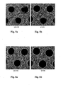
- Figs. 5a and 5b are images comparing porous alpha-alumina membranes prepared from a coating solution without skim milk ( Fig. 5a ) and with skim milk ( Fig. 5b ).
- Figs. 6a and 6b are images comparing porous alpha-alumina membranes prepared from a coating solution without skim milk ( Fig. 6a ) and with skim milk ( Fig. 6b ).
- Fig. 7 is a graph illustrating the pore size distributions of three unsupported alumina membranes made of different alumina materials.
- Figs. 8a and 8b are SEM images of the channel surfaces of alumina membranes AA-07/AKP30 ( Fig. 8a ) and AA-07/A-16 ( Fig. 8b ).
- Fig. 9 is a graph illustrating pore size distributions of alumina membranes AKP30 (made without pore former) and AKP30M (made with pore former).
- Figs. 10a and 10b are SEM images of channel surfaces coated with an AA-07/AKP30M alumina coating.
- Figs. 11 a and 11 b are SEM images of cross-sectional views of AKP30 and AKP30M coatings as underlying layers for a gamma-alumina coating of finer pores.
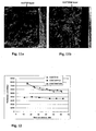
- Fig. 12 is a graph illustrating the pure water permeability of different membrane coatings at room temperature.
- Fig. 13 is a graph illustrating filtration efficiency of different membrane coatings at room temperature.
- Fig. 14 is a schematic of a flow coating process and apparatus useful in an embodiment of the invention.
- An embodiment of the invention is a method for preparing a porous inorganic coating on a porous support, which comprises:
- the porous support used in the invention may be in the form of, for example, a honeycomb monolith.
- the method of the invention works advantageously well in depositing membranes within honeycomb channels of small diameter.
- the porous support such as a honeycomb monolith, could have a channel density of, for example, from 50 to 600 cells per square inch.
- Example honeycomb monolith supports are disclosed in U.S. Patent Nos. 3,885,977 and 3,790,654 , the contents of both being incorporated by reference herein.
- the channels are plugged at one end of the support, while other channels are plugged at the other end of the support.
- the plugged and/or unplugged channels form a checkerboard pattern with each other.
- one channel is plugged on one end (referred to as “the reference end") but not the opposite end of the support
- at least some, for example a majority, of the channels (preferably all of the channels in certain other embodiments) immediately proximate thereto (those sharing at least one wall with the channel of concern) are plugged at such opposite end of the support but not on the reference end.
- individual supports such as honeycombs can be stacked or housed in various manners to form larger supports having various sizes, service duration, and the like, to meet the needs of differing use conditions.
- the support is an inorganic material.
- Suitable porous inorganic support materials include ceramic, glass ceramic, glass, metal, clays, and combinations thereof.
- materials include cordierite, mullite, clay, magnesia, metal oxides, talc, zircon, zirconia, zirconates, zirconia-spinel, magnesium alumino-silicates, spinel, alumina, silica, silicates, borides, alumino-silicates, e.g., porcelains, lithium aluminosilicates, alumina silica, feldspar, titania, fused silica, nitrides, borides, carbides, e.g., silicon carbide, silicon nitride or combinations of these.
- the porous inorganic support could be a ceramic, such as cordierite, alumina (such as alpha-alumina), mullite, aluminum titinate, titania, zirconia, ceria or combinations thereof.
- a ceramic such as cordierite, alumina (such as alpha-alumina), mullite, aluminum titinate, titania, zirconia, ceria or combinations thereof.
- the porous support is an alpha-alumina support as disclosed in co-pending U.S. Application No. 60/874,070, filed on December 11, 2006 , and titled “Alpha-Alumina Inorganic Membrane Support and Method of Making the Same," the contents of which are incorporated by reference herein.
- the support can be made, for example, according to a process comprising:
- the support can comprise an organic material, such as a phenolic resin.
- the support structure should have adequate thermal stability so that it maintains a useful shape upon application of heat when carrying out the methods of the invention.
- the porous support "provided" according to the invention may be a unitary structure, such as a bare ceramic support.
- the inner channels of the support have surfaces defined by porous walls of the unitary porous ceramic support.
- the porous support "provided" according to the invention may comprise a unitary structure, such as a ceramic support, already coated with a porous material that forms the porous walls of the inner channels of the support.
- That pre-existing coating may be, for example, one or more coatings of inorganic particles, such as alpha-alumina particles.
- the inner channels of the provided support have surfaces defined by the porous coating of inorganic particles.
- the method of the invention is carried out beginning with a coated support and results in the deposition of a further coating of inorganic particles placed over the previous coating. That embodiment may be carried out, for example, to ultimately deposit a coating of inorganic particles of a smaller median diameter over a pre-existing coating of inorganic particles having a larger median diameter.
- the porous support "provided" according to the invention comprises a ceramic already pre-coated with a porous membrane of inorganic particles that forms the porous walls of the inner channels of the support.
- the pre-coat may be in the form of one or several layers.
- the pre-coat itself can be applied by any method, including a method of the invention having been performed on a bare ceramic support.
- the pre-coat itself discussed above can also be applied using techniques disclosed in U.S. application no. 11/880,066, filed on July 19, 2007 , the contents of which are incorporated by reference herein. More specifically, the pre-coat can be applied according to a method that comprises:
- the porous support "provided" according to the invention comprises a ceramic having inner channel surfaces that have been modified by application of a composition comprising an organic pore-filling material selected from protein particles, starch particles, synthetic polymer particles, and combinations thereof.
- a composition comprising an organic pore-filling material selected from protein particles, starch particles, synthetic polymer particles, and combinations thereof.
- Such a composition may be skim milk used to supply the protein particles.
- the method of the invention could then carried out on such a modified support that, for example, has been dried after application of the pore-filling material.
- the method would comprise:
- the porous support 10 is a multi-channel structure, in particular a cylindrical structure (length not illustrated), comprising a plurality of inner channels 12 defined by porous walls 14 throughout its cross-section.
- the inner channels of the support can be circular and have an average diameter of, for instance, from 0.5 to 10 mm, for example from 0.5 to 2 mm.
- the length of the support may be selected in view of its particular application.
- the support may have a length of 80 mm or more, for example 100 mm, 150 mm or 200 mm or more.
- the support may have a length of 0.5 m or more, or 1.0 m or more.
- the invention can be applied to supports having a wide range of porosities and pore sizes on the porous walls that define the inner channel surfaces of the provided support.
- the pores of the porous walls of the provided support have a median pore size of from 0.5 to 100 ⁇ m, for example from 0.5 to 10 ⁇ m.
- a coating comprising inorganic particles and an organic pore-forming material selected from protein particles, starch particles, synthetic polymer particles, and combinations thereof, is applied to the inner channel surfaces of the support.
- the porosity and pore-sizes of the inorganic porous coatings ultimately made according to the invention are influenced by the addition of the organic pore-formers at this stage.
- the organic pore-forming material comprises protein particles.
- Protein particles may be supplied, for example, by contacting the inner channel surfaces of the support with a composition comprising an aqueous suspension of protein particles.
- a composition comprising an aqueous suspension of protein particles.
- an aqueous suspension of protein particles is skim milk.
- the organic pore-filling material comprises starch particles, such as amaranth starch (for example, having a mean diameter of 1.5 ⁇ m), quinoa starch (for example, having a mean diameter of 1.8 ⁇ m), taro starch (for example, having a mean diameter of 2.8 ⁇ m), or combinations thereof.
- the organic pore-forming material comprises synthetic polymer particles, such as polystyrene, polyacrylate, an oligomer, or combinations thereof.
- Example oligomers include polyolefins having a molecular weight of 5000 daltons or less.
- the particle size of the organic pore-forming material can be selected depending on the characteristics of the support, such as its pore size or pore size distribution, and on the characteristics of the inorganic particles that will be subsequently applied, such as their particle size.
- the organic pore-forming material may comprise particles having a median particle size of from 0.02 to 3 ⁇ m.
- the particle size distribution of the pore-forming material may also be selected depending on the desired characteristics of the resulting coating.
- the particle size distribution of the pore-forming material meets the condition (d90-d10)/d50 ⁇ 2, for example ⁇ 1.6, ⁇ 1.5, ⁇ 1.2 or ⁇ 1.1, where particles having a size of d90 or less, d50 or less, and d10 or less account for 90%, 50%, and 10% of the of the total light intensity, respectively.
- the pore-forming material comprises protein particles that meet the condition (d90-d10)/d50 ⁇ 1.6.
- the pore-forming material comprises starch particles that meet the condition (d90-d10)/d50 ⁇ 1.1.
- inorganic particles may be used in the coating of the invention, including but not limited to cordierite, alumina (such as alpha-alumina and gamma-alumina), mullite, aluminum titinate, titania, zirconia, and ceria particles and combinations thereof.
- the size of the inorganic particles may be selected depending, for example, on the pore size of the underlying modified support. For instance, the inorganic particles may have a median particle size of from 0.02 to 10 ⁇ m.
- the coating comprising inorganic particles and the organic pore-forming material may be applied, for example, by contacting the provided support with a composition comprising them.
- the coating composition may comprise, for instance, from 0.1 to 50 wt. % of inorganic particles. Generally speaking, higher inorganic particle concentrations tend to produce a thicker, more viscous slip, which in turn tends to produce a thicker coating on the support.
- the coating composition may also comprise, for example, a dispersant, a binder, an anti-cracking agent, an antifoam agent, or combinations thereof, and may comprise an aqueous or organic carrier and is in the form of a suspension.
- the coating comprising inorganic particles and the organic pore-forming material may be applied to the inner channel surfaces of the support through various methods, for example, by dip coating, flow coating, slip-casting, immersion, or combinations thereof. Using these methods, membrane materials are transported from a fluid medium onto the channel walls and deposited on the wall surfaces, leaving an intact deposition layer after the fluid is discharged.
- the coating is deposited as a coating slip on the porous support while the provided support is mounted inside a flow coater illustrated in Fig. 14 , as discussed in co-pending U.S. application no. 11/729,732, filed on March 29, 2007 , and titled "Method and Apparatus for Membrane Deposition," the contents of which are incorporated by reference herein.
- This technique includes providing a liquid precursor comprising membrane-forming materials to the support and applying a pressure differential across the support. The pressure differential causes the liquid precursor to travel uniformly through the channels, depositing the membrane-forming materials on the walls of the channels and forming the membrane on the walls of the through-channels.
- a liquid precursor coating solution 1402 to a monolith support 1404, such as a monolith honeycomb structure, a chamber 1406 capable of holding the support and maintaining a pressure differential across the plurality of through-channels, and an outlet.
- a monolith support 1404 such as a monolith honeycomb structure
- a chamber 1406 capable of holding the support and maintaining a pressure differential across the plurality of through-channels
- the thickness, texture, and uniformity of the deposited membrane films may be controlled by process conditions. It will be apparent that the process conditions that are actually employed in the deposition of such membrane films depend on the nature of the membrane film and the liquid precursor, as well as other variables. For example, the linear velocity of the liquid precursor through the plurality of through-channels affects the hydrodynamics and mass transport of the liquid precursor onto the walls of the plurality of through-channels. In one embodiment, the liquid precursor flows through the plurality of through-channels at a predetermined linear velocity.
- the resulting coated support may then be dried under a variety of conditions.
- the coated support may be dried for 15-25 hours at room temperature or higher up to 120 °C in an air or nitrogen atmosphere. Drying may also be conducted under conditions of 60-90% humidity.
- the drying step in one embodiment, is carried out in a controlled gas environment.
- the controlled gas environment is one in which the content of at least one of oxygen and water content is controlled.
- the oxygen content of the controlled atmosphere is typically kept to a minimum.
- the coated support is then heated, for example fired, to remove the organic pore-forming material, leaving a porous inorganic coating on the underlying porous support.
- the inorganic particles in the porous inorganic coating can be sintered.
- the support may be fired at 900°C to 1500°C for a period of from 0.5 to 10 hours in a controlled gas environment at a heating rate of, for example, 0.5-2 °C/min.
- the firing process can be executed for 20-45 hours at 1100-1300 °C in air or in a mixture of nitrogen and oxygen.
- the coated support is heated to calcinate the organic pore-forming material, for example at a temperature of 600 °C or more, then fired at a higher temperature to achieve sintering of the inorganic particles.
- the resulting sintered porous inorganic coating has a thickness of from 0.2 to 25 ⁇ m throughout the length of the inner channels, which could be throughout a length of 80 mm or more.
- the thickness of the coating can be increased by simply repeating the application of the same size particles in additional coating steps.
- the pore size of the inorganic coating can be selected through appropriate choice of, for example, the inorganic particle size, the type and size of pore-forming material, and sintering conditions.
- the sintered inorganic coating has a median pore size of from 0.01 to 2 ⁇ m.
- a coated porous support prepared by the method of the invention may comprises:
- the coated support may exhibit a steady state pure water permeance of 2500 L/m 2 /h/bar or more at 22 °C, for example 4000 L/m 2 /h/bar or more or 5000 L/m 2 /h/bar or more.
- the coatings on the supports may be used as inorganic membranes suitable for liquid filtration and gas separation applications.
- the separations could be achieved by passing the liquid or gas stream through the channels of the coated support to effect the desired separation.
- the coatings can also be applicable to automotive catalytic products and diesel particulate filter products.
- the methods described herein can provide direct deposition of coatings with small pores on-a porous support with large pores, while reducing coating thickness, and thereby reducing costs and enhancing the permeation flux.
- the methods described herein can enable deposition of a uniform, thin layer catalyst on a porous support and minimize penetration of the catalyst material into the support pores, thereby resulting in better catalyst utilization, significant cost saving in the precious metal catalyst as well as reduced heating costs.
- the coated supports may furthermore be used as intermediate structures in processes that deposit additional membranes on the coated supports. Accordingly, it will be understood that the methods described herein can be used to manufacture membranes for use in a variety of applications.
- Example 1 Application of pre-coat to alpha alumina monolith support
- the bare monolith support is made of alpha-alumina with an outer diameter of 8.7-10.0 mm and a length of 80-150 mm and comprising 19 rounded channels of average diameter of 0.75 mm uniformly distributed over the cross-sectional area.
- the median pore size of the bare support is 8.4-8.7 ⁇ m and porosity is 43.5-50.8% as measured by Hg porosimetry.
- a pre-coating of inorganic particles was first applied to the support.
- the support was flushed through the channels with D.I. water.
- the support was fully dried at 120 °C in an oven overnight.
- the support was modified by application of skim milk (Great ValueTM) using a flow-coater illustrated in Fig. 14 .
- the soaking time was 20 seconds.
- the modified support was dried at ambient conditions for 23 hours.
- the dried support was mounted into the flow coater again and coated with a 30 wt. % alumina slip AA-3.
- the resulting alumina membrane was characterized by SEM.
- Figs. 2a and 2b show SEM images of the channel surface of the bare support and pre-coat layer, respectively.
- Fig. 2c is a cross-section illustrating a pre-coat thickness of about 40 ⁇ m.
- the mean pore size is approximately 800 nm.
- Example 2 Deposition of alpha-alumina membranes without the use of a pore-former
- Inorganic membrane coatings often encounter problems of mud cracking, de-lamination, and pore closure.
- Some anti cracking organic materials such as, PEG, PVP, PVA, etc, are often used in the coating slip. However, in many cases, those additives are not effective.
- This example describes deposition of two porous alpha-alumina membranes using a general coating solution formulation comprising different alumina materials.
- the same alumina monolith support as described in Example 1 was used.
- Two 10 wt. % water-based alumina coating solutions were prepared using PEG as an anti-cracking agent and Tiron as a dispersant. The only difference between these two slips lies in the raw alumina materials used.
- alumina particles of a mean particle size of 0.8-1.1 um from Sumitomo Chemical were used, while the other coating slip (A-16) used alumina of a mean particle size of 0.3-0.4 um from Alcoa Industrial Chemicals.
- the coating solution AA-07 was prepared as follows. First, 0.13 g Tiron was added into a 150 ml plastic jar containing 100 g D.I. water, followed by adding 26 g alumina AA-07.
- the coated slip was further mixed with 52.78 g D.I. water, 38.89 g 20 wt. % PEG and 2.80 g 1% DCB. After ball-milling for 15-20 h, the slip was poured through a fine screen (opening size of 0.037 mm) into a flask, followed by degassing with a vacuum pump.
- the coating solution A-16 was prepared using the same procedure.
- the two alumina coating slips (AA-07 and A-16) were applied on to the pre-coated support (see Example 1) by use of a flow-coater shown in Fig. 14 .
- the same procedure was used for each, which included loading the monolith sample on the coater, introduction of coating slip and soaking, unloading the sample, and spinning the sample to remove the excess coating solution.
- the soaking time was 20 seconds, and the spinning speed was set at 725 rpm with spinning time of 60 seconds.
- the same coating process was repeated once in order to reduce defects.
- the coated sample was dried at 120 °C and fired at 1250 °C with a heating rate of 1 °C/min in a flow reactor to remove all the organic and sinter the coating layer. Referring to Figs. 3a (AA-07) and 3b (A-16), the SEM images show that both membranes have serious problems of cracking and de-lamination, even though anti-cracking agent PEG had been added.
- Example 3 Deposition of alpha-alumina membranes using protein from skim milk as a pore former
- pore structure In addition to cracking and de-lamination problems, another problem encountered with inorganic membrane coatings relates to pore structure. For high flux, uniform pore structures and large porosity is desired. However, in conventional coating processes, pore structures are generally formed from particle packing during drying and firing process, thus limiting porosity.
- This example demonstrates feasibility of an alumina membrane coating using skim milk as a pore former.
- Two water-based coating solutions were made containing 17 wt. % skim milk (Great ValueTM) having a mean particle size of the skim milk around 0.40 um, which was measured by use of a Nanotrac Particle size analyzer.
- the two coating slips, AA-07M and A-16M, of the present example were prepared by mixing 100 g of the coating solution, 10 wt% AA-07 and 10 wt% A-16 prepared in Example 2, with 20 g skim milk at ambient condition, respectively.
- the porous alpha-alumina membrane layer was prepared with the AA-07M or A-16M coating slip by use of the same procedures and parameters as used in Example 2. Scanning electron microscope (SEM) analysis showed that a highly porous alpha-alumina membrane layer was formed on the pre-coated supports, with the SEM analysis for AA-07M shown in the top view of Fig. 4a and the cross-sectional view of 4b. Fig. 4b illustrates the support 10, the pre-coat 40 and the outer membrane layer 50. Another benefit was found that the pore former (skim milk) can be used as an anti-cracking agent and adhesion agent.
- SEM scanning electron microscope
- the SEM analysis of the cross-sectional views indicates de-lamination occurred with a coating made without the use of a pore former ( Fig. 5a ), but did not occur when the pore former was used ( Fig. 5b ).
- the cracking problems present in the coating made without the use of a pore former as shown in Fig. 6a may be reduced or eliminated by the addition of a pore former as shown in Fig. 6b .
- Example 4 Deposition of porous alpha-alumina membranes with graded pore structures without the use of a pore former of the invention
- This example describes deposition of two porous alpha-alumina membranes with graded pore structure.
- a multilayer membrane with graded pore structure has less flow resistance and therefore high flux.
- the same alumina pre-coat monolith support in Example 1 was used as the support for this coating.
- Three 5 wt. % water-based alumina coating solutions used here were prepared using PEG as an anti-cracking agent and Tiron as a dispersant. The only difference of three slips was raw alumina materials.
- AA-07, A-16, and AKP30 (Sumitomo Chemical) have a mean particle size of 0.8-1.1 ⁇ m, 0.3-0.4 um, and 0.2-0.3 um, respectively.
- the 5 wt. % alumina coating solutions were prepared using the same procedure as the following example with the AA-07.
- Tiron 0.06 g Tiron was added into a 150 ml plastic jar containing 100 g D.I. water, followed by adding 12 g alumina AA-07. After the jar was shaken for a while, it was put into an ice bath with ice cover around. Then, an ultrasonic horn was put down into the jar and the ultrasonic treatment was run for 30 times with 10 sec ON and 30 sec OFF. The treated slip was then mixed with 45.3 g D.I. water, 99.13 g 20 wt. % PEG and 3.40 g 1% DCB. After ball-milling for 15-20 h, the slip was poured through a fine screen into a flask, followed by degassing with a vacuum pump.
- Two layers of the alumina membrane were prepared using different slips containing gradually smaller particle size.
- a first layer AA-07 was made on the pre-coated support using the slip of 5 wt. % AA-07.
- the same coating procedure and parameters as in Example 2 was used.
- a second layer A-16 was coated on top of the AA-07 coating using the slip of 5 wt. % A-16 with the same procedure.
- the two-layer membrane was fired at 1250 °C for 15 min with a heating rate of 1 °C/min.
- the other membrane AA-07/AKP30 was made by the same way using 5 wt. % AA-07 and 5 wt. % AKP30.
- the graph of Fig. 7 compares the pore size distributions of the alumina powders prepared from the coating slips AA-07, A-16 and AKP30, by use of the same drying and firing conditions as the membrane formation.
- the membrane coating slips AA-07 and A-16 have narrow single mode pore size distribution with a peak pore size of 420 and 220 nm, respectively.
- the membrane slip AKP30 has a wide pore size distribution with several peaks at 14, 100, 270 nm. SEM images show that the membrane AA-07/AKP30 has no visible crack, while AA-07/A-16 has some cracks and penetration, as shown in Figs. 8a and 8b , respectively.
- Example 5 Deposition of alpha-alumina membrane using protein particles from skim milk as pore former
- This example describes another deposition of multi-layer alpha-alumina membrane using skim milk as a pore former.
- Two water-based alumina coating solutions used here were 5 wt. % AA-07 and 5 wt. % AKP30M.
- the preparation procedure for the slip AA-07 was the same as in Example 4.
- the slip AKP30M contained 17 wt. % skim milk, which serves as a pore former. The same skim milk as in Example 3 was used.
- the coating slip AKP30M was made by mixing 100 g coating solution having 5 wt. % AKP30 (in Example 4) with 20 g skim milk at ambient conditions.
- the alumina membrane AA-07/AKP30M was prepared by sequential coating of the monolith substrate with the AA07 and AKP30M coating slip, as described in Example 4. The resulting two-layer membrane coating was fired at 1150 °C for 2 hours.
- the graph of Fig. 9 shows the effect of pore former on pore size distribution of the resulting porous alumina structure. As shown, the addition of the pore former makes the pore size narrower.
- Figs: 10a and 10b using different magnifications, show a uniform, crack-free surface of the resulting AA-07/AKP30M membrane structure.
- Fig. 10a illustrates two channel surfaces 60 and porous wall 62.
- Fig. 10b illustrates a higher magnification of one of the channel surfaces 60.
- 11 a and 11 b show the use of the AKP30 and AKP30M coatings as an underlying layer for a gamma-alumina membrane coating having finer pores, such as for a gas-separation application. As shown, the AKP30M coating layer appears more porous than the AKP30 coating structure.
- Fig. 12 shows permeance of the water through three different membrane structures, AA-07/A-16, AA-07/AKP30, and AA-07/AKP30M.
- Figure 12 shows that the AA-07/A-16 and AA-07/AKP30M membrane structure has substantially higher permeability than the AA07/AKP30.
- the higher permeability of the AA-07/A16 than the AA-07/AKP30 is expected, since the A-16 coating layer has much larger pore sizes than the AKP30 layer, and even has some cracks.
- the higher permeability of the AA-07/AKP30M than the AA-07/AKP30 demonstrates a permeability advantage of the present invention through use of the skim milk pore former over AKP30.
- Permeability is one characteristic of the membrane structure.
- Another property of the membrane structure is filtration function.
- the filtration efficiency was characterized by conduct cross-flow filtration with a polyacrylate/water mixture.
- the mixture contains polyacrylate particles of size ranging from approximately 100 to approximately 500 nm.
- the mixture looks cloudy and has a turbidity unit number (nephelometric turbidity unit, NTU) of approximately 600.
- NTU turbidity unit number
- Clarity of the permeate is a direct indication to the filtration efficiency of the membrane structure.
- the graph of Fig. 13 plots the variation of NTU of the permeate against the time on stream.
- the NTU numbers for the permeate of the AA-07/A-16 membrane structure equals about 80, which indicates lesser filtration efficiency consistent with the large pore size and cracks of the AA-07/A-16 membrane coating.
- NTU numbers for the permeate from the AA-07/AKP30M and the AA-07/AKP30 are all low, ⁇ 0.5, which indicates an excellent filtration performance.
- the membrane structure AA-07/AKP30M prepared from the present invention shows similar or slightly better filtration efficiency than the AA07/AKP30 and substantially higher permeability.
- wt % or “weight percent” or “percent by weight” of a component, unless specifically stated to the contrary, is based on the total weight of the composition or article in which the component is included.
Description
- This application claims the benefit of priority to
U.S. application no. 60/932,462, filed on May 31, 2007 U.S. application no. 11/880,073, filed July 19, 2007 - The invention relates to a method for preparing a porous inorganic coating on a porous support using certain pore formers.
- The porous inorganic coatings may serve as membranes useful in, for example, liquid-liquid, liquid-particulate, gas-gas, or gas-particulate separation applications.
- An inorganic membrane may be applied, for example, as a porous coating on a porous ceramic support. Inorganic membranes offer several advantages over organic membranes. Inorganic membranes, for example, typically have high chemical and thermal stabilities that allow the membranes to be used in extreme pH and chemical environments. In addition, inorganic membranes can be easily cleaned by applying high temperature treatments such as firing.
- Inorganic membranes may be used for filtration and separation applications in the environmental, biological, food and drink, semiconductor, chemical, petrochemical, gas and energy industries. These industries often require purified gas/vapor or purified liquid whose source is a mixed feed stream composed of different gas and/or liquid/particulate combinations. Specific examples include purification and separation of hydrogen gas, sequestration of carbon dioxide gas, filtration of oil/water mixtures, wastewater treatment, filtration of wines and juices, filtration of bacteria and viruses from fluid streams, separation of ethanol from biomass, and production of high purity gas and water for the semiconductor and microelectronics industry.
- Inorganic membranes may be applied as layered structures comprising a porous inorganic monolayer or multilayer coating on a porous support, such as a ceramic support. The porous coating layer is generally prepared by dipping the support into a coating slip and by subsequently withdrawing it out of that slip, followed by drying and firing.
- The coating slip is a dispersion of solid particles in a liquid. Fine particles that are in the colloidal range (≤ 1um) usually aggregate in the dispersing medium due to relatively high strength of the inter-particle van der Waals attractive forces. Thus, a dispersant such as Darvan C, Tiron or Aluminon is often introduced to build up a repulsive force barrier and to stabilize the slips (Briscoe, Khan, Luckham, J. Europ. Ceram. Soc., 18 (1998) 2141-2147). Also, coating slips generally contain more than one polymeric compound, such as surfactants, lubricants, and plasticizers. The interaction between all these compounds determines the slip behavior and the microstructure development during compaction, drying and calcining (Burggraaf and Cot, Fundamentals of Inorganic Membrane Science and Technology, Elsevier Science B.V., 1996, Page 157).
-
WO 85/01937 -
EP 0344961 B1 discusses another formulation of an inorganic coating slip used for coating on a porous metal. The slip comprises 60-95% by weight of relatively larger inorganic particles such as alumina and zirconia, the balance being of much smaller particles. The larger particles may have an average in the range of 0.5-50 um, chosen to generate membranes with pores of desired size. The smaller particles may have an average size of 4 nm up to 1 um, but not more than 0.1 times the size of the larger particles. The smaller particles act as a sintering aid, enabling the membrane to be sintered at lower temperatures. The portions of the smaller particles should not be too large to substantially block the pores between the larger particles. - Inorganic membrane coatings furthermore often encounter problems of mud cracking, de-lamination, and pore closure. Some anti cracking organic materials, such as, PEG, PVP, PVA, etc, are often used in the coating slip. However, in many cases, those additives are not effective. Another problem encountered with inorganic membrane coating relates to pore structure. For high flux, uniform pore structures and large porosity is desired. However, in conventional coating processes, pore structures are generally formed from particle packing during drying and firing process, thus limiting porosity.
- Document
WO 2006/130759 A2 discloses a ceramic forming batch mixture including inorganic batch material, a pore-former combination including first and second pore-formers with different compositions, an organic binder and a solvent. There, the first pore former may consist of starch in 5% to 15%, by weight, of the inorganic batch materials, and the second pore former may consist of graphite in 5% to 15%, by weight of the inorganic batch materials. - BHATTACHARJEE ET AL: "Effect of additives on the microstructure of porous alumina", JOURNAL OF THE EUROPEAN CERAMIC SOCIETY, ELSEVIER SCIENCE PUBLISHERS, BARKING, ESSEX, GB, vol. 27, no. 1, 6 November 2006 (2008-11-06), pages 47-52, XP005848773, ISSN: 0955-2219 discloses protein forming as a direct consolidation technique for shaping of powders into a rigid body by using globular protein as gelling agent. In particular, the foaming and gelling capabilities of globular protein (albumin) along with starch to consolidate a ceramic body to develop porous structure based on alumina are described.
- Document
US 2005/0046063 A1 further relates to a method for manufacturing a porous ceramic structure which comprises molding a raw material which contains a ceramic material as a main component and a pore-forming agent and then drying and firing the obtained molded article. - Document
US 4 980 062 A relates to a process for preparing microporous inorganic membranes comprising mixing a sol comprised of inorganic colloidal particles dispersed in liquid medium with an organic polymeric film forming material dissolved in a suitable solvent. -
Document EP 0 732 139 A2 discloses a tubular solid-state membrane module for separating oxygen from an oxygen-containing gaseous mixture. The modules are formed from a plurality of tubular membrane units, each comprising a channel-free porous support having connected through porosity which is in contact with a contiguous dense mixed conducting oxide layer having no connected through porosity. - In view of the above, there is a need in the art for more favorable processes for depositing porous membranes of inorganic particles on porous supports.
- The invention relates to methods for preparing porous inorganic coatings on porous supports using certain pore formers (i.e., pore formers added with the inorganic particles forming the coating), and to porous supports coated with porous inorganic coatings. A method of the invention comprises:
- providing a porous support comprising a first end, a second end, and a plurality of inner channels having surfaces defined by porous walls and extending through the support from the first end to the second end;
- applying to the inner channel surfaces of the support a coating suspension comprising inorganic particles and an organic pore-forming material selected from protein particles, starch particles, synthetic polymer particles, and combinations thereof; and
- heating the coated support to remove the organic pore-forming material, leaving a porous inorganic coating on the porous support.
- This and additional features provided by embodiments of the present invention will be more fully discussed in the following detailed description.
-
Fig. 1 is a schematic of a multi-channel porous support useful in an embodiment of the invention. -
Figs. 2a-2c are scanning electron microscope (SEM) images of a bare support and the pre-coated support, whereFig. 2a illustrates the surface morphology of the bare support,Fig. 2b illustrates the surface morphology of the pre-coat formed on the support, andFig. 2c provides a cross-sectional view of the pre-coated support. -
Figs. 3a and 3b are SEM images of the surface morphology of two alumina coatings, AA-07 (Fig. 3a ) and A-16 (Fig. 3b ), which were not made using organic pore formers of the invention. -
Fig. 4a is a top view SEM image andFig. 4b is a cross-section SEM, image of a porous alumina membrane AA-07, made using skim milk as a pore former, deposited on a pre-coated alumina support. -
Figs. 5a and 5b are images comparing porous alpha-alumina membranes prepared from a coating solution without skim milk (Fig. 5a ) and with skim milk (Fig. 5b ). -
Figs. 6a and 6b are images comparing porous alpha-alumina membranes prepared from a coating solution without skim milk (Fig. 6a ) and with skim milk (Fig. 6b ). -
Fig. 7 is a graph illustrating the pore size distributions of three unsupported alumina membranes made of different alumina materials. -
Figs. 8a and 8b are SEM images of the channel surfaces of alumina membranes AA-07/AKP30 (Fig. 8a ) and AA-07/A-16 (Fig. 8b ). -
Fig. 9 is a graph illustrating pore size distributions of alumina membranes AKP30 (made without pore former) and AKP30M (made with pore former). -
Figs. 10a and 10b are SEM images of channel surfaces coated with an AA-07/AKP30M alumina coating. -
Figs. 11 a and 11 b are SEM images of cross-sectional views of AKP30 and AKP30M coatings as underlying layers for a gamma-alumina coating of finer pores. -
Fig. 12 is a graph illustrating the pure water permeability of different membrane coatings at room temperature. -
Fig. 13 is a graph illustrating filtration efficiency of different membrane coatings at room temperature. -
Fig. 14 is a schematic of a flow coating process and apparatus useful in an embodiment of the invention. - The embodiments set forth in the figures are illustrative in nature and not intended to be limiting of the invention defined by the claims. Moreover, individual features of the drawings and the invention will be more fully discussed in view of the detailed description.
- An embodiment of the invention is a method for preparing a porous inorganic coating on a porous support, which comprises:
- providing a porous support comprising a first end, a second end, and a plurality of inner channels having surfaces defined by porous walls and extending through the support from the first end to the second end;
- applying to the inner channel surfaces of the support a coating comprising inorganic particles and an organic pore-forming material selected from protein particles, starch particles, synthetic polymer particles, and combinations thereof; and
- heating the coated support to remove the organic pore-forming material, leaving a porous inorganic coating on the porous support.
- The porous support used in the invention may be in the form of, for example, a honeycomb monolith. The method of the invention works advantageously well in depositing membranes within honeycomb channels of small diameter. The porous support, such as a honeycomb monolith, could have a channel density of, for example, from 50 to 600 cells per square inch. Example honeycomb monolith supports are disclosed in
U.S. Patent Nos. 3,885,977 and3,790,654 , the contents of both being incorporated by reference herein. - To allow for more intimate contact between a fluid stream flowing through the support and the coated support itself, for example when used in a separation application, it is desired in certain embodiments that at least some of the channels are plugged at one end of the support, while other channels are plugged at the other end of the support. In certain embodiments, it is desired that at each end of the support, the plugged and/or unplugged channels form a checkerboard pattern with each other. In certain embodiments, it is desired that where one channel is plugged on one end (referred to as "the reference end") but not the opposite end of the support, at least some, for example a majority, of the channels (preferably all of the channels in certain other embodiments) immediately proximate thereto (those sharing at least one wall with the channel of concern) are plugged at such opposite end of the support but not on the reference end. Furthermore, individual supports such as honeycombs can be stacked or housed in various manners to form larger supports having various sizes, service duration, and the like, to meet the needs of differing use conditions.
- In one embodiment, the support is an inorganic material. Suitable porous inorganic support materials include ceramic, glass ceramic, glass, metal, clays, and combinations thereof. Some example, materials include cordierite, mullite, clay, magnesia, metal oxides, talc, zircon, zirconia, zirconates, zirconia-spinel, magnesium alumino-silicates, spinel, alumina, silica, silicates, borides, alumino-silicates, e.g., porcelains, lithium aluminosilicates, alumina silica, feldspar, titania, fused silica, nitrides, borides, carbides, e.g., silicon carbide, silicon nitride or combinations of these.
- In view of the above, the porous inorganic support could be a ceramic, such as cordierite, alumina (such as alpha-alumina), mullite, aluminum titinate, titania, zirconia, ceria or combinations thereof.
- In one embodiment, the porous support is an alpha-alumina support as disclosed in co-pending
U.S. Application No. 60/874,070, filed on December 11, 2006 - combining 60 weight% to 70 weight% α-alumina comprising a particle size in the range of 5µm to 30µm, 30 weight % of an organic pore former comprising a particle size in the range of 7µm to 45µm, 10 weight % of a sintering aid, and other batch components such as crosslinker, etc., to form a batch;
- mixing the batch and allowing it to soak for 8 hours to 16 hours;
- shaping a green body by extrusion; and
- sintering the green body by heating the green body at a temperature of at least 1500 °C for 8 hours to 16 hours.
- In another embodiment, the support can comprise an organic material, such as a phenolic resin. In any event, the support structure should have adequate thermal stability so that it maintains a useful shape upon application of heat when carrying out the methods of the invention.
- The porous support "provided" according to the invention may be a unitary structure, such as a bare ceramic support. In that instance, the inner channels of the support have surfaces defined by porous walls of the unitary porous ceramic support.
- In another embodiment, the porous support "provided" according to the invention may comprise a unitary structure, such as a ceramic support, already coated with a porous material that forms the porous walls of the inner channels of the support. That pre-existing coating may be, for example, one or more coatings of inorganic particles, such as alpha-alumina particles. In that instance, the inner channels of the provided support have surfaces defined by the porous coating of inorganic particles. Thus, in that embodiment, the method of the invention is carried out beginning with a coated support and results in the deposition of a further coating of inorganic particles placed over the previous coating. That embodiment may be carried out, for example, to ultimately deposit a coating of inorganic particles of a smaller median diameter over a pre-existing coating of inorganic particles having a larger median diameter.
- In one embodiment, the porous support "provided" according to the invention comprises a ceramic already pre-coated with a porous membrane of inorganic particles that forms the porous walls of the inner channels of the support. The pre-coat may be in the form of one or several layers. The pre-coat itself can be applied by any method, including a method of the invention having been performed on a bare ceramic support.
- The pre-coat itself discussed above can also be applied using techniques disclosed in
U.S. application no. 11/880,066, filed on July 19, 2007 - providing a porous support comprising a first end, a second end, and a plurality of inner channels having surfaces defined by porous walls and extending through the support from the first end to the second end;
- modifying the inner channel surfaces of the support by applying to the inner channel surfaces a composition comprising an organic pore-filling material selected from protein particles, starch particles, synthetic polymer particles, and combinations thereof;
- applying to the modified inner channel surfaces a coating comprising inorganic particles; and
- heating the coated support to remove the organic pore-filling material, leaving a porous inorganic coating on the porous support.
- In yet a further embodiment, the porous support "provided" according to the invention comprises a ceramic having inner channel surfaces that have been modified by application of a composition comprising an organic pore-filling material selected from protein particles, starch particles, synthetic polymer particles, and combinations thereof. Such a composition may be skim milk used to supply the protein particles. The method of the invention could then carried out on such a modified support that, for example, has been dried after application of the pore-filling material. Thus, in combination with the modification step, the method would comprise:
- providing a porous support comprising a first end, a second end, and a plurality of inner channels having surfaces defined by porous walls and extending through the support from the first end to the second end;
- modifying the inner channel surfaces of the support by applying to the inner channel surfaces a composition comprising an organic pore-filling material selected from protein particles, starch particles, synthetic polymer particles, and combinations thereof;
- applying to the modified inner channel surfaces of the support a coating comprising inorganic particles and an organic pore-forming material selected from protein particles, starch particles, synthetic polymer particles, and combinations thereof; and
- heating the coated support to remove the organic pore-forming material and pore-filling material, leaving a porous inorganic coating on the porous support.
- Referring to
Fig. 1 , an exemplary multi-channelporous support 10 is illustrated. In this embodiment, theporous support 10 is a multi-channel structure, in particular a cylindrical structure (length not illustrated), comprising a plurality ofinner channels 12 defined byporous walls 14 throughout its cross-section. In this and other embodiments, the inner channels of the support can be circular and have an average diameter of, for instance, from 0.5 to 10 mm, for example from 0.5 to 2 mm. The length of the support may be selected in view of its particular application. For example, the support may have a length of 80 mm or more, for example 100 mm, 150 mm or 200 mm or more. On a larger scale, the support may have a length of 0.5 m or more, or 1.0 m or more. - The invention can be applied to supports having a wide range of porosities and pore sizes on the porous walls that define the inner channel surfaces of the provided support. In one embodiment, the pores of the porous walls of the provided support have a median pore size of from 0.5 to 100 µm, for example from 0.5 to 10 µm.
- A coating comprising inorganic particles and an organic pore-forming material selected from protein particles, starch particles, synthetic polymer particles, and combinations thereof, is applied to the inner channel surfaces of the support. The porosity and pore-sizes of the inorganic porous coatings ultimately made according to the invention are influenced by the addition of the organic pore-formers at this stage.
- In one embodiment, the organic pore-forming material comprises protein particles. Protein particles may be supplied, for example, by contacting the inner channel surfaces of the support with a composition comprising an aqueous suspension of protein particles. One example of an aqueous suspension of protein particles is skim milk. In another embodiment, the organic pore-filling material comprises starch particles, such as amaranth starch (for example, having a mean diameter of 1.5 µm), quinoa starch (for example, having a mean diameter of 1.8 µm), taro starch (for example, having a mean diameter of 2.8 µm), or combinations thereof. In yet another embodiment, the organic pore-forming material comprises synthetic polymer particles, such as polystyrene, polyacrylate, an oligomer, or combinations thereof. Example oligomers include polyolefins having a molecular weight of 5000 daltons or less.
- The particle size of the organic pore-forming material can be selected depending on the characteristics of the support, such as its pore size or pore size distribution, and on the characteristics of the inorganic particles that will be subsequently applied, such as their particle size. For example, the organic pore-forming material may comprise particles having a median particle size of from 0.02 to 3 µm.
- The particle size distribution of the pore-forming material may also be selected depending on the desired characteristics of the resulting coating. In one embodiment, the particle size distribution of the pore-forming material, as measured by dynamic light scattering, meets the condition (d90-d10)/d50 ≤ 2, for example ≤ 1.6, ≤ 1.5, ≤ 1.2 or ≤ 1.1, where particles having a size of d90 or less, d50 or less, and d10 or less account for 90%, 50%, and 10% of the of the total light intensity, respectively. In another embodiment, the pore-forming material comprises protein particles that meet the condition (d90-d10)/d50 ≤ 1.6. In another embodiment, the pore-forming material comprises starch particles that meet the condition (d90-d10)/d50 ≤ 1.1.
- A wide variety of inorganic particles may be used in the coating of the invention, including but not limited to cordierite, alumina (such as alpha-alumina and gamma-alumina), mullite, aluminum titinate, titania, zirconia, and ceria particles and combinations thereof. The size of the inorganic particles may be selected depending, for example, on the pore size of the underlying modified support. For instance, the inorganic particles may have a median particle size of from 0.02 to 10 µm.
- The coating comprising inorganic particles and the organic pore-forming material may be applied, for example, by contacting the provided support with a composition comprising them. The coating composition may comprise, for instance, from 0.1 to 50 wt. % of inorganic particles. Generally speaking, higher inorganic particle concentrations tend to produce a thicker, more viscous slip, which in turn tends to produce a thicker coating on the support. The coating composition may also comprise, for example, a dispersant, a binder, an anti-cracking agent, an antifoam agent, or combinations thereof, and may comprise an aqueous or organic carrier and is in the form of a suspension.
- The coating comprising inorganic particles and the organic pore-forming material may be applied to the inner channel surfaces of the support through various methods, for example, by dip coating, flow coating, slip-casting, immersion, or combinations thereof. Using these methods, membrane materials are transported from a fluid medium onto the channel walls and deposited on the wall surfaces, leaving an intact deposition layer after the fluid is discharged.
- In one embodiment, the coating is deposited as a coating slip on the porous support while the provided support is mounted inside a flow coater illustrated in
Fig. 14 , as discussed in co-pendingU.S. application no. 11/729,732, filed on March 29, 2007 Fig. 14 , includes an inlet that uniformly distributes a liquidprecursor coating solution 1402 to amonolith support 1404, such as a monolith honeycomb structure, achamber 1406 capable of holding the support and maintaining a pressure differential across the plurality of through-channels, and an outlet. - The thickness, texture, and uniformity of the deposited membrane films may be controlled by process conditions. It will be apparent that the process conditions that are actually employed in the deposition of such membrane films depend on the nature of the membrane film and the liquid precursor, as well as other variables. For example, the linear velocity of the liquid precursor through the plurality of through-channels affects the hydrodynamics and mass transport of the liquid precursor onto the walls of the plurality of through-channels. In one embodiment, the liquid precursor flows through the plurality of through-channels at a predetermined linear velocity.
- The resulting coated support may then be dried under a variety of conditions. For example, the coated support may be dried for 15-25 hours at room temperature or higher up to 120 °C in an air or nitrogen atmosphere. Drying may also be conducted under conditions of 60-90% humidity. The drying step, in one embodiment, is carried out in a controlled gas environment. The controlled gas environment is one in which the content of at least one of oxygen and water content is controlled. The oxygen content of the controlled atmosphere is typically kept to a minimum.
- The coated support is then heated, for example fired, to remove the organic pore-forming material, leaving a porous inorganic coating on the underlying porous support. During the same or different heating step, the inorganic particles in the porous inorganic coating can be sintered. In one embodiment, the support may be fired at 900°C to 1500°C for a period of from 0.5 to 10 hours in a controlled gas environment at a heating rate of, for example, 0.5-2 °C/min. In another embodiment, the firing process can be executed for 20-45 hours at 1100-1300 °C in air or in a mixture of nitrogen and oxygen. In yet another embodiment, the coated support is heated to calcinate the organic pore-forming material, for example at a temperature of 600 °C or more, then fired at a higher temperature to achieve sintering of the inorganic particles.
- In one embodiment, the resulting sintered porous inorganic coating has a thickness of from 0.2 to 25 µm throughout the length of the inner channels, which could be throughout a length of 80 mm or more. The thickness of the coating can be increased by simply repeating the application of the same size particles in additional coating steps.
- The pore size of the inorganic coating can be selected through appropriate choice of, for example, the inorganic particle size, the type and size of pore-forming material, and sintering conditions. In one embodiment, the sintered inorganic coating has a median pore size of from 0.01 to 2 µm.
- A coated porous support prepared by the method of the invention may comprises:
- a porous support comprising a first end, a second end, and a plurality of inner channels that have surfaces defined by an outer porous coating of inorganic particles and that extend through the support from the first end to the second end;
- wherein the porosity of the outer coating of inorganic particles, measured by mercury porosimetry, is 40% or higher, for example 50% or higher; and
- wherein the pore size distribution of the outer porous coating of inorganic particles, measured by mercury porosimetry, meets the condition (d90-d10)/d50 ≤ 2, for example ≤ 1.5,
- ≤ 1.2, or ≤ 1.0, where pores having a size of d90 or less, d50 or less, and d10 or less account for 90%, 50%, and 10% of the of the total pore volume, respectively.
- The coated support may exhibit a steady state pure water permeance of 2500 L/m2/h/bar or more at 22 °C, for example 4000 L/m2/h/bar or more or 5000 L/m2/h/bar or more.
- The coatings on the supports may be used as inorganic membranes suitable for liquid filtration and gas separation applications. The separations could be achieved by passing the liquid or gas stream through the channels of the coated support to effect the desired separation. The coatings can also be applicable to automotive catalytic products and diesel particulate filter products.
- For membrane filtration or separation applications, the methods described herein can provide direct deposition of coatings with small pores on-a porous support with large pores, while reducing coating thickness, and thereby reducing costs and enhancing the permeation flux. For catalytic applications, the methods described herein can enable deposition of a uniform, thin layer catalyst on a porous support and minimize penetration of the catalyst material into the support pores, thereby resulting in better catalyst utilization, significant cost saving in the precious metal catalyst as well as reduced heating costs. The coated supports may furthermore be used as intermediate structures in processes that deposit additional membranes on the coated supports. Accordingly, it will be understood that the methods described herein can be used to manufacture membranes for use in a variety of applications.
- Membrane coating experiments in this example are discussed with respect to a porous alpha alumina monolith support. The bare monolith support is made of alpha-alumina with an outer diameter of 8.7-10.0 mm and a length of 80-150 mm and comprising 19 rounded channels of average diameter of 0.75 mm uniformly distributed over the cross-sectional area. The median pore size of the bare support is 8.4-8.7 µm and porosity is 43.5-50.8% as measured by Hg porosimetry.
- A pre-coating of inorganic particles was first applied to the support. The support was flushed through the channels with D.I. water. The support was fully dried at 120 °C in an oven overnight. The support was modified by application of skim milk (Great Value™) using a flow-coater illustrated in
Fig. 14 . The soaking time was 20 seconds. The modified support was dried at ambient conditions for 23 hours. The dried support was mounted into the flow coater again and coated with a 30 wt. % alumina slip AA-3. After dried at 120 °C and fired at 1400 °C for 2 hours, the resulting alumina membrane was characterized by SEM.Figs. 2a and 2b show SEM images of the channel surface of the bare support and pre-coat layer, respectively.Fig. 2c is a cross-section illustrating a pre-coat thickness of about 40 µm. The mean pore size is approximately 800 nm. - Inorganic membrane coatings often encounter problems of mud cracking, de-lamination, and pore closure. Some anti cracking organic materials, such as, PEG, PVP, PVA, etc, are often used in the coating slip. However, in many cases, those additives are not effective.
- This example describes deposition of two porous alpha-alumina membranes using a general coating solution formulation comprising different alumina materials. The same alumina monolith support as described in Example 1 was used.
- Two 10 wt. % water-based alumina coating solutions were prepared using PEG as an anti-cracking agent and Tiron as a dispersant. The only difference between these two slips lies in the raw alumina materials used. In one coating slip (AA-07), alumina particles of a mean particle size of 0.8-1.1 um from Sumitomo Chemical were used, while the other coating slip
(A-16) used alumina of a mean particle size of 0.3-0.4 um from Alcoa Industrial Chemicals. The coating solution AA-07 was prepared as follows. First, 0.13 g Tiron was added into a 150 ml plastic jar containing 100 g D.I. water, followed by adding 26 g alumina AA-07. After the jar was shaken for a while, it was put into an ice bath with ice cover around. Then, an ultrasonic horn was put down into the jar and the ultrasonic treatment was run for 30 times with 10 sec ON and 30 sec OFF. The treated slip was further mixed with 52.78 g D.I. water, 38.89g 20 wt. % PEG and 2.80g 1% DCB. After ball-milling for 15-20 h, the slip was poured through a fine screen (opening size of 0.037 mm) into a flask, followed by degassing with a vacuum pump. The coating solution A-16 was prepared using the same procedure. - The two alumina coating slips (AA-07 and A-16) were applied on to the pre-coated support (see Example 1) by use of a flow-coater shown in
Fig. 14 . The same procedure was used for each, which included loading the monolith sample on the coater, introduction of coating slip and soaking, unloading the sample, and spinning the sample to remove the excess coating solution. The soaking time was 20 seconds, and the spinning speed was set at 725 rpm with spinning time of 60 seconds. The same coating process was repeated once in order to reduce defects. Then, the coated sample was dried at 120 °C and fired at 1250 °C with a heating rate of 1 °C/min in a flow reactor to remove all the organic and sinter the coating layer. Referring toFigs. 3a (AA-07) and 3b (A-16), the SEM images show that both membranes have serious problems of cracking and de-lamination, even though anti-cracking agent PEG had been added. - In addition to cracking and de-lamination problems, another problem encountered with inorganic membrane coatings relates to pore structure. For high flux, uniform pore structures and large porosity is desired. However, in conventional coating processes, pore structures are generally formed from particle packing during drying and firing process, thus limiting porosity.
- This example demonstrates feasibility of an alumina membrane coating using skim milk as a pore former. Two water-based coating solutions were made containing 17 wt. % skim milk (Great Value™) having a mean particle size of the skim milk around 0.40 um, which was measured by use of a Nanotrac Particle size analyzer. The two coating slips, AA-07M and
A-16M, of the present example were prepared by mixing 100 g of the coating solution, 10 wt% AA-07 and 10 wt% A-16 prepared in Example 2, with 20 g skim milk at ambient condition, respectively. - The porous alpha-alumina membrane layer was prepared with the AA-07M or A-16M coating slip by use of the same procedures and parameters as used in Example 2. Scanning electron microscope (SEM) analysis showed that a highly porous alpha-alumina membrane layer was formed on the pre-coated supports, with the SEM analysis for AA-07M shown in the top view of
Fig. 4a and the cross-sectional view of 4b.Fig. 4b illustrates thesupport 10, the pre-coat 40 and theouter membrane layer 50. Another benefit was found that the pore former (skim milk) can be used as an anti-cracking agent and adhesion agent. Referring toFigs 5a and 5b , the SEM analysis of the cross-sectional views indicates de-lamination occurred with a coating made without the use of a pore former (Fig. 5a ), but did not occur when the pore former was used (Fig. 5b ). Similarly, the cracking problems present in the coating made without the use of a pore former as shown inFig. 6a may be reduced or eliminated by the addition of a pore former as shown inFig. 6b . - This example describes deposition of two porous alpha-alumina membranes with graded pore structure. A multilayer membrane with graded pore structure has less flow resistance and therefore high flux. The same alumina pre-coat monolith support in Example 1 was used as the support for this coating.
- Three 5 wt. % water-based alumina coating solutions used here were prepared using PEG as an anti-cracking agent and Tiron as a dispersant. The only difference of three slips was raw alumina materials. AA-07, A-16, and AKP30 (Sumitomo Chemical) have a mean particle size of 0.8-1.1 µm, 0.3-0.4 um, and 0.2-0.3 um, respectively. The 5 wt. % alumina coating solutions were prepared using the same procedure as the following example with the AA-07.
- First, 0.06 g Tiron was added into a 150 ml plastic jar containing 100 g D.I. water, followed by adding 12 g alumina AA-07. After the jar was shaken for a while, it was put into an ice bath with ice cover around. Then, an ultrasonic horn was put down into the jar and the ultrasonic treatment was run for 30 times with 10 sec ON and 30 sec OFF. The treated slip was then mixed with 45.3 g D.I. water, 99.13
g 20 wt. % PEG and 3.40g 1% DCB. After ball-milling for 15-20 h, the slip was poured through a fine screen into a flask, followed by degassing with a vacuum pump. - Two layers of the alumina membrane were prepared using different slips containing gradually smaller particle size. For the membrane AA-07/A-16, a first layer AA-07 was made on the pre-coated support using the slip of 5 wt. % AA-07. The same coating procedure and parameters as in Example 2 was used. After drying at 120 °C and polymer-bum out at 600 °C, a second layer A-16 was coated on top of the AA-07 coating using the slip of 5 wt. % A-16 with the same procedure. After drying, the two-layer membrane was fired at 1250 °C for 15 min with a heating rate of 1 °C/min. The other membrane AA-07/AKP30 was made by the same way using 5 wt. % AA-07 and 5 wt. % AKP30.
- According to the particle dense packing theory, the larger particles form larger pores. The graph of
Fig. 7 compares the pore size distributions of the alumina powders prepared from the coating slips AA-07, A-16 and AKP30, by use of the same drying and firing conditions as the membrane formation. The membrane coating slips AA-07 and A-16 have narrow single mode pore size distribution with a peak pore size of 420 and 220 nm, respectively. The membrane slip AKP30 has a wide pore size distribution with several peaks at 14, 100, 270 nm. SEM images show that the membrane AA-07/AKP30 has no visible crack, while AA-07/A-16 has some cracks and penetration, as shown inFigs. 8a and 8b , respectively. - This example describes another deposition of multi-layer alpha-alumina membrane using skim milk as a pore former. Two water-based alumina coating solutions used here were 5 wt. % AA-07 and 5 wt. % AKP30M. The preparation procedure for the slip AA-07 was the same as in Example 4. The slip AKP30M contained 17 wt. % skim milk, which serves as a pore former. The same skim milk as in Example 3 was used. The coating slip AKP30M was made by mixing 100 g coating solution having 5 wt. % AKP30 (in Example 4) with 20 g skim milk at ambient conditions. The alumina membrane AA-07/AKP30M was prepared by sequential coating of the monolith substrate with the AA07 and AKP30M coating slip, as described in Example 4. The resulting two-layer membrane coating was fired at 1150 °C for 2 hours.
- The graph of
Fig. 9 shows the effect of pore former on pore size distribution of the resulting porous alumina structure. As shown, the addition of the pore former makes the pore size narrower.Figs: 10a and 10b , using different magnifications, show a uniform, crack-free surface of the resulting AA-07/AKP30M membrane structure.Fig. 10a illustrates twochannel surfaces 60 andporous wall 62.Fig. 10b illustrates a higher magnification of one of the channel surfaces 60.Figs. 11 a and 11 b show the use of the AKP30 and AKP30M coatings as an underlying layer for a gamma-alumina membrane coating having finer pores, such as for a gas-separation application. As shown, the AKP30M coating layer appears more porous than the AKP30 coating structure. - The permeability of the membrane coatings prepared in above Examples 4 and 5 was measured with de-ionized water on a laboratory-scale filtration testing apparatus. The water flows through the membrane channel at a linear velocity of about 170 cm/s. A pressure gradient of approximately 25 psi was maintained between the flow channel and exterior of the monolith membrane body. Under such a pressure driving force, the water flows across the membrane coating layer from the channel, permeates through the porous support matrix, and comes out at the exterior of the monolith body.
Fig. 12 shows permeance of the water through three different membrane structures, AA-07/A-16, AA-07/AKP30, and AA-07/AKP30M. The permeance measures permeability of the membrane structure and is calculated from the following equation:
where P = permeance, L/m2/h/bar; VP = water permeation flow rate out of the testing membrane sample, Uh; SAM = membrane surface area in all the channels that are exposed to the permeation fluid, m2; and TMP = trans-membrane pressure, bar. -
Figure 12 shows that the AA-07/A-16 and AA-07/AKP30M membrane structure has substantially higher permeability than the AA07/AKP30. The higher permeability of the AA-07/A16 than the AA-07/AKP30 is expected, since the A-16 coating layer has much larger pore sizes than the AKP30 layer, and even has some cracks. The higher permeability of the AA-07/AKP30M than the AA-07/AKP30 demonstrates a permeability advantage of the present invention through use of the skim milk pore former over AKP30. - Permeability is one characteristic of the membrane structure. Another property of the membrane structure is filtration function. The filtration efficiency was characterized by conduct cross-flow filtration with a polyacrylate/water mixture. The mixture contains polyacrylate particles of size ranging from approximately 100 to approximately 500 nm. The mixture looks cloudy and has a turbidity unit number (nephelometric turbidity unit, NTU) of approximately 600. The filtration test was conducted in a similar manner to the permeability testing. Under a drive force of trans-membrane pressure, the water flows across the membrane and permeates out of the monolith support body, while the particles are blocked by the membrane coating. The permeate was collected and measured for NTU number. Clarity of the permeate is a direct indication to the filtration efficiency of the membrane structure. The graph of
Fig. 13 plots the variation of NTU of the permeate against the time on stream. The NTU numbers for the permeate of the AA-07/A-16 membrane structure equals about 80, which indicates lesser filtration efficiency consistent with the large pore size and cracks of the AA-07/A-16 membrane coating. By contrast, NTU numbers for the permeate from the AA-07/AKP30M and the AA-07/AKP30 are all low, <0.5, which indicates an excellent filtration performance. ComparingFig. 13 to Fig. 12 , the membrane structure AA-07/AKP30M prepared from the present invention shows similar or slightly better filtration efficiency than the AA07/AKP30 and substantially higher permeability. - Unless otherwise indicated, all numbers such as those expressing weight percents of ingredients, dimensions, and values for certain physical properties used in the specification and claims are to be understood as being modified in all instances by the term "about." It should also be understood that the precise numerical values used in the specification and claims form additional embodiments of the invention. Efforts have been made to ensure the accuracy of the numerical values disclosed in the Examples. Any measured numerical value, however, can inherently contain certain errors resulting from the standard deviation found in its respective measuring technique.
- Furthermore, as used herein, in describing and claiming the present invention, the use of the indefinite article "a" or "an" includes one or more of the recited elements and should not be limited to "only one" unless explicitly indicated to the contrary.
- Also as used herein, a "wt %" or "weight percent" or "percent by weight" of a component, unless specifically stated to the contrary, is based on the total weight of the composition or article in which the component is included.
Claims (9)
- A method for preparing a porous inorganic coating on a porous support, which comprises:providing a porous support (10) comprising a first end, a second end, and a plurality of inner channels (12) having surfaces defined by porous walls (14) and extending through the support from the first end to the second end;applying to the inner channel surfaces of the support (10) a coating suspension comprising inorganic particles and an organic pore-forming material selected from protein particles, starch particles, synthetic polymer particles, and combinations thereof; andheating the coated support (10) to remove the organic pore-forming material, leaving a porous inorganic coating on the porous support.
- The method of claim 1, wherein the provided porous support (10) is in the form of a honeycomb monolith.
- The method of claim 1, wherein the provided porous support (10) is inorganic.
- The method of claim 3, wherein the provided porous inorganic support (10) is ceramic, wherein the inner channels (12) have surfaces defined by porous walls (14) of the porous ceramic support.
- The method of claim 1, wherein the organic pore-forming material comprises protein particles.
- The method of claim 1, wherein the organic pore-forming material comprises synthetic polymer particles.
- The method of claim 1, wherein the inorganic particles used in the coating include cordierite, alumina, mullite, aluminum titinate, titania, zirconia, or ceria particles or combinations thereof.
- The method of claim 1, wherein heating the coated support (10) to remove the organic pore-forming material comprises firing the coated support (10) to calcinate the organic pore-forming material, leaving a porous inorganic coating on the porous support.
- The method of claim 1, which further comprises sintering the inorganic particles in the porous inorganic coating.
Applications Claiming Priority (3)
| Application Number | Priority Date | Filing Date | Title |
|---|---|---|---|
| US93246207P | 2007-05-31 | 2007-05-31 | |
| US11/880,073 US7767257B2 (en) | 2007-05-31 | 2007-07-19 | Method for preparing a porous inorganic coating on a porous support using certain pore formers |
| PCT/US2008/006819 WO2008153828A2 (en) | 2007-05-31 | 2008-05-29 | Method for preparing a porous inorganic coating on a porous support using certain pore formers |
Publications (2)
| Publication Number | Publication Date |
|---|---|
| EP2066426A2 EP2066426A2 (en) | 2009-06-10 |
| EP2066426B1 true EP2066426B1 (en) | 2013-04-17 |
Family
ID=40088598
Family Applications (1)
| Application Number | Title | Priority Date | Filing Date |
|---|---|---|---|
| EP20080754803 Expired - Fee Related EP2066426B1 (en) | 2007-05-31 | 2008-05-29 | Method for preparing a porous inorganic coating on a porous support using certain pore formers |
Country Status (7)
| Country | Link |
|---|---|
| US (1) | US7767257B2 (en) |
| EP (1) | EP2066426B1 (en) |
| JP (1) | JP5302957B2 (en) |
| KR (1) | KR101501792B1 (en) |
| CN (1) | CN101678281B (en) |
| TW (1) | TWI388372B (en) |
| WO (1) | WO2008153828A2 (en) |
Families Citing this family (34)
| Publication number | Priority date | Publication date | Assignee | Title |
|---|---|---|---|---|
| WO2010062794A1 (en) * | 2008-11-26 | 2010-06-03 | Corning Incorporated | Coated particulate filter and method |
| US20100184197A1 (en) * | 2009-01-22 | 2010-07-22 | Longying Dong | Methods For Harvesting Biological Materials Using Membrane Filters |
| US8101010B2 (en) * | 2009-05-28 | 2012-01-24 | Corning Incorporated | Gas separation module |
| US7989373B2 (en) * | 2009-06-30 | 2011-08-02 | Corning Incorporated | Hermetic sealing material |
| US20110160048A1 (en) * | 2009-12-29 | 2011-06-30 | Boumendjel Nariman | Coating method for structured catalysts |
| WO2011149744A1 (en) * | 2010-05-25 | 2011-12-01 | Corning Incorporated | Cordierite membrane on a cordierite monolith |
| US9878272B2 (en) | 2010-05-28 | 2018-01-30 | Corning Incorporated | Porous inorganic membranes and method of manufacture |
| CN103080046B (en) * | 2010-09-01 | 2016-02-17 | 陶氏环球技术有限责任公司 | For discriminating layer being applied to the method on porous ceramic filter |
| US8685144B2 (en) | 2010-11-12 | 2014-04-01 | The Texas A&M University System | System and method for efficient air dehumidification and liquid recovery |
| US8685145B2 (en) | 2010-11-12 | 2014-04-01 | The Texas A&M University System | System and method for efficient multi-stage air dehumidification and liquid recovery |
| US8685142B2 (en) | 2010-11-12 | 2014-04-01 | The Texas A&M University System | System and method for efficient air dehumidification and liquid recovery with evaporative cooling |
| MX2013005224A (en) | 2010-11-12 | 2013-07-03 | Texas A & M Univ Sys | Systems and methods for air dehumidification and sensible cooling using a multiple stage pump. |
| US8784541B2 (en) * | 2011-11-10 | 2014-07-22 | Corning Incorporated | Cordierite-based composite membrane coated on cordierite monolith |
| US10286391B2 (en) | 2012-02-17 | 2019-05-14 | Inaeris Technologies, Llc | Catalyst system having meso and macro hierarchical pore structure |
| US20150027871A1 (en) * | 2012-02-17 | 2015-01-29 | Kior, Inc. | Catalyst Compositions Comprising In Situ Grown Zeolites on Clay Matrixes Exhibiting Hierarchical Pore Structures |
| US10124300B2 (en) * | 2012-02-28 | 2018-11-13 | Massachusetts Institute Of Technology | Flux-enhanced hierarchical porous membrane for oil-water nanoemulsion separation |
| JP2014188492A (en) * | 2013-03-28 | 2014-10-06 | Kubota Corp | Membrane element and production method of membrane element |
| JP6349706B2 (en) * | 2013-12-11 | 2018-07-04 | 株式会社明電舎 | Manufacturing method of ceramic filter |
| CN104326719B (en) * | 2014-10-07 | 2016-08-24 | 唐世群 | Good water-retaining property exterior wall heat-insulating paint |
| JP6219871B2 (en) * | 2015-03-27 | 2017-10-25 | トヨタ自動車株式会社 | Exhaust gas purification catalyst |
| JP6219872B2 (en) * | 2015-03-27 | 2017-10-25 | トヨタ自動車株式会社 | Exhaust gas purification catalyst |
| JP2018533471A (en) | 2015-10-30 | 2018-11-15 | コーニング インコーポレイテッド | Porous ceramic filter and method of manufacturing the same |
| CN106925135A (en) * | 2017-02-24 | 2017-07-07 | 华南理工大学 | A kind of composite ceramics grid film and preparation method thereof |
| CN116078052A (en) | 2017-10-31 | 2023-05-09 | 康宁股份有限公司 | Honeycomb body and particle filter comprising a honeycomb body |
| DE102018106260B4 (en) * | 2018-03-16 | 2019-12-24 | Siemens Aktiengesellschaft | Process for producing a ceramic absorber, ceramic absorber and use of the same |
| CN109020622A (en) * | 2018-07-27 | 2018-12-18 | 四川大学 | A method of regulation porous material hole structure |
| KR102493620B1 (en) * | 2018-09-14 | 2023-01-30 | 주식회사 엘지화학 | Ceramic membrane and method for preparing same |
| KR102508586B1 (en) * | 2018-09-27 | 2023-03-09 | 주식회사 엘지화학 | Ceramic membrane and method for preparing same |
| US11819806B1 (en) | 2018-10-15 | 2023-11-21 | Ampcera Inc. | Methods for manufacturing a solid state ionic conductive membrane on a macro porous support scaffold |
| US11177498B1 (en) | 2018-10-15 | 2021-11-16 | Ampcera Inc. | Redox flow batteries, components for redox flow batteries and methods for manufacture thereof |
| WO2020107286A1 (en) * | 2018-11-28 | 2020-06-04 | 湖南中锂新材料有限公司 | Porous coating film, and preparation method therefor and application thereof |
| US11600853B1 (en) | 2019-05-14 | 2023-03-07 | Ampcera Inc. | Systems and methods for storing, transporting, and handling of solid-state electrolytes |
| DE102019121084A1 (en) | 2019-08-05 | 2021-02-11 | Umicore Ag & Co. Kg | Catalyst substrates with porous coating |
| WO2021257582A1 (en) * | 2020-06-15 | 2021-12-23 | Metalmark Innovations, Inc. | Porous materials for treating contaminants |
Family Cites Families (17)
| Publication number | Priority date | Publication date | Assignee | Title |
|---|---|---|---|---|
| NL8303079A (en) | 1983-09-05 | 1985-04-01 | Stichting Energie | PROCESS FOR THE PREPARATION OF CRACK-FREE SEMI-PERMEABLE INORGANIC MEMBRANES. |
| FR2553758B1 (en) | 1983-10-25 | 1991-07-05 | Ceraver | POROUS MATERIAL AND TUBULAR FILTER COMPRISING SUCH MATERIAL |
| US5120576A (en) | 1988-05-24 | 1992-06-09 | Ceramem Separations Limited Partnership | Impregnating porous inorganic membrane with reactive inorganic binder |
| GB8812217D0 (en) | 1988-05-24 | 1988-06-29 | Alcan Int Ltd | Composite membranes |
| US4929406A (en) | 1988-05-27 | 1990-05-29 | Ngk Insulators, Ltd. | Process for producing an inorganic porous membrane |
| US4980062A (en) | 1988-09-16 | 1990-12-25 | W. R. Grace & Co.-Conn. | Inorganic membrane |
| JPH02102723A (en) * | 1988-10-12 | 1990-04-16 | Ngk Insulators Ltd | Inorganic porous membrane |
| FR2693921B1 (en) | 1992-07-24 | 1994-09-30 | Tech Sep | Monolithic ceramic support for tangential filtration membrane. |
| BR9406483A (en) | 1993-04-23 | 1996-01-09 | Exxon Chemical Patents Inc | Layer and processes for preparing it to separate a fluid mixture and to catalyze a chemical reaction |
| US5599383A (en) | 1995-03-13 | 1997-02-04 | Air Products And Chemicals, Inc. | Tubular solid-state membrane module |
| JP3750178B2 (en) * | 1995-04-05 | 2006-03-01 | 株式会社デンソー | Exhaust gas purification filter and manufacturing method thereof |
| FR2826956B1 (en) * | 2001-07-04 | 2004-05-28 | Air Liquide | PROCESS FOR PREPARING A LOW THICKNESS CERAMIC COMPOSITION WITH TWO MATERIALS, COMPOSITION OBTAINED, ELECTROCHEMICAL CELL AND MEMBRANE COMPRISING IT |
| JP2003212672A (en) * | 2002-01-21 | 2003-07-30 | Ngk Insulators Ltd | Process for manufacturing porous ceramic structure |
| US7429351B2 (en) | 2002-01-21 | 2008-09-30 | Ngk Insulators, Ltd. | Method for manufacturing a porous ceramic structure |
| JP2003210922A (en) * | 2002-01-23 | 2003-07-29 | Ibiden Co Ltd | Ceramic honeycomb filter |
| US7387829B2 (en) | 2004-01-13 | 2008-06-17 | Ibiden Co., Ltd. | Honeycomb structure, porous body, pore forming material for the porous body, and methods for manufacturing the pore forming material, the porous body and the honeycomb structure |
| EP1890983B1 (en) | 2005-05-31 | 2012-12-12 | Corning Incorporated | Aluminum titanate ceramic forming batch mixtures and green bodies including pore former combinations and methods of manufacturing and firing same |
-
2007
- 2007-07-19 US US11/880,073 patent/US7767257B2/en active Active
-
2008
- 2008-05-29 KR KR1020097027501A patent/KR101501792B1/en not_active IP Right Cessation
- 2008-05-29 CN CN2008800176904A patent/CN101678281B/en not_active Expired - Fee Related
- 2008-05-29 TW TW97119990A patent/TWI388372B/en not_active IP Right Cessation
- 2008-05-29 EP EP20080754803 patent/EP2066426B1/en not_active Expired - Fee Related
- 2008-05-29 WO PCT/US2008/006819 patent/WO2008153828A2/en active Application Filing
- 2008-05-29 JP JP2010510346A patent/JP5302957B2/en not_active Expired - Fee Related
Also Published As
| Publication number | Publication date |
|---|---|
| TWI388372B (en) | 2013-03-11 |
| JP5302957B2 (en) | 2013-10-02 |
| CN101678281A (en) | 2010-03-24 |
| US7767257B2 (en) | 2010-08-03 |
| WO2008153828A2 (en) | 2008-12-18 |
| CN101678281B (en) | 2012-09-05 |
| JP2010528835A (en) | 2010-08-26 |
| WO2008153828A3 (en) | 2009-02-19 |
| TW200920472A (en) | 2009-05-16 |
| KR20100028067A (en) | 2010-03-11 |
| EP2066426A2 (en) | 2009-06-10 |
| US20080299377A1 (en) | 2008-12-04 |
| KR101501792B1 (en) | 2015-03-11 |
Similar Documents
| Publication | Publication Date | Title |
|---|---|---|
| EP2066426B1 (en) | Method for preparing a porous inorganic coating on a porous support using certain pore formers | |
| EP2150513B1 (en) | Method for preparing a porous inorganic coating on a porous support using certain pore fillers | |
| JP2010528835A5 (en) | ||
| US20190202747A1 (en) | Inorganic membrane filter and methods thereof | |
| EP2689828B1 (en) | Honeycomb-shaped ceramic separation-membrane structure | |
| Agrafiotis et al. | Deposition of meso-porous γ-alumina coatings on ceramic honeycombs by sol-gel methods | |
| US8481110B2 (en) | Methods of making inorganic membranes | |
| US5773103A (en) | Inorganic membranes using porous cordierite support | |
| WO2008010452A1 (en) | Ceramic filter | |
| US10183242B2 (en) | Porous inorganic membranes and method of manufacture | |
| CN108883377B (en) | Porous support, method for producing porous support, separation membrane structure, and method for producing separation membrane structure | |
| JP5082067B2 (en) | Method for producing high-strength macroporous porous ceramic and porous body thereof | |
| KR102076733B1 (en) | MANUFACTURING METHOD OF CERAMIC MEMBRANE SURFACE MODIFIED WITH SiO2 AND TiO2 | |
| JP6417355B2 (en) | Monolith type separation membrane structure | |
| JP2002219318A (en) | gamma-ALUMINA POROUS BODY, METHOD FOR MANUFACTURING THE SAME AND FLUID SEPARATION FILTER USING THE POROUS BODY |
Legal Events
| Date | Code | Title | Description |
|---|---|---|---|
| PUAI | Public reference made under article 153(3) epc to a published international application that has entered the european phase |
Free format text: ORIGINAL CODE: 0009012 |
|
| 17P | Request for examination filed |
Effective date: 20090330 |
|
| AK | Designated contracting states |
Kind code of ref document: A2 Designated state(s): AT BE BG CH CY CZ DE DK EE ES FI FR GB GR HR HU IE IS IT LI LT LU LV MC MT NL NO PL PT RO SE SI SK TR |
|
| AX | Request for extension of the european patent |
Extension state: AL BA MK RS |
|
| 17Q | First examination report despatched |
Effective date: 20090710 |
|
| REG | Reference to a national code |
Ref country code: DE Ref legal event code: 8566 |
|
| RIN1 | Information on inventor provided before grant (corrected) |
Inventor name: WANG, JIANGUO Inventor name: GU, YUNFENG Inventor name: LIU, WEI Inventor name: ST. CLAIR, TODD, P. |
|
| RBV | Designated contracting states (corrected) |
Designated state(s): FR GB NL NO |
|
| DAX | Request for extension of the european patent (deleted) | ||
| GRAP | Despatch of communication of intention to grant a patent |
Free format text: ORIGINAL CODE: EPIDOSNIGR1 |
|
| GRAS | Grant fee paid |
Free format text: ORIGINAL CODE: EPIDOSNIGR3 |
|
| GRAA | (expected) grant |
Free format text: ORIGINAL CODE: 0009210 |
|
| AK | Designated contracting states |
Kind code of ref document: B1 Designated state(s): FR GB NL NO |
|
| REG | Reference to a national code |
Ref country code: GB Ref legal event code: FG4D |
|
| REG | Reference to a national code |
Ref country code: NL Ref legal event code: T3 |
|
| PG25 | Lapsed in a contracting state [announced via postgrant information from national office to epo] |
Ref country code: NO Free format text: LAPSE BECAUSE OF FAILURE TO SUBMIT A TRANSLATION OF THE DESCRIPTION OR TO PAY THE FEE WITHIN THE PRESCRIBED TIME-LIMIT Effective date: 20130717 |
|
| PLBE | No opposition filed within time limit |
Free format text: ORIGINAL CODE: 0009261 |
|
| STAA | Information on the status of an ep patent application or granted ep patent |
Free format text: STATUS: NO OPPOSITION FILED WITHIN TIME LIMIT |
|
| 26N | No opposition filed |
Effective date: 20140120 |
|
| REG | Reference to a national code |
Ref country code: FR Ref legal event code: PLFP Year of fee payment: 8 |
|
| PGFP | Annual fee paid to national office [announced via postgrant information from national office to epo] |
Ref country code: GB Payment date: 20150527 Year of fee payment: 8 |
|
| PGFP | Annual fee paid to national office [announced via postgrant information from national office to epo] |
Ref country code: FR Payment date: 20150519 Year of fee payment: 8 Ref country code: NL Payment date: 20150526 Year of fee payment: 8 |
|
| REG | Reference to a national code |
Ref country code: NL Ref legal event code: MM Effective date: 20160601 |
|
| GBPC | Gb: european patent ceased through non-payment of renewal fee |
Effective date: 20160529 |
|
| PG25 | Lapsed in a contracting state [announced via postgrant information from national office to epo] |
Ref country code: NL Free format text: LAPSE BECAUSE OF NON-PAYMENT OF DUE FEES Effective date: 20160601 |
|
| REG | Reference to a national code |
Ref country code: FR Ref legal event code: ST Effective date: 20170131 |
|
| PG25 | Lapsed in a contracting state [announced via postgrant information from national office to epo] |
Ref country code: FR Free format text: LAPSE BECAUSE OF NON-PAYMENT OF DUE FEES Effective date: 20160531 |
|
| PG25 | Lapsed in a contracting state [announced via postgrant information from national office to epo] |
Ref country code: GB Free format text: LAPSE BECAUSE OF NON-PAYMENT OF DUE FEES Effective date: 20160529 |