WO2017169331A1 - 水陸両用車 - Google Patents
水陸両用車 Download PDFInfo
- Publication number
- WO2017169331A1 WO2017169331A1 PCT/JP2017/006629 JP2017006629W WO2017169331A1 WO 2017169331 A1 WO2017169331 A1 WO 2017169331A1 JP 2017006629 W JP2017006629 W JP 2017006629W WO 2017169331 A1 WO2017169331 A1 WO 2017169331A1
- Authority
- WO
- WIPO (PCT)
- Prior art keywords
- wheel
- cover
- wheel cover
- vehicle body
- suspension
- Prior art date
- Legal status (The legal status is an assumption and is not a legal conclusion. Google has not performed a legal analysis and makes no representation as to the accuracy of the status listed.)
- Ceased
Links
Images







Classifications
-
- B—PERFORMING OPERATIONS; TRANSPORTING
- B60—VEHICLES IN GENERAL
- B60F—VEHICLES FOR USE BOTH ON RAIL AND ON ROAD; VEHICLES CAPABLE OF TRAVELLING IN OR ON DIFFERENT MEDIA, e.g. AMPHIBIOUS VEHICLES
- B60F3/00—Amphibious vehicles, i.e. vehicles capable of travelling both on land and on water; Land vehicles capable of travelling under water
- B60F3/0007—Arrangement of propulsion or steering means on amphibious vehicles
- B60F3/0015—Arrangement of propulsion or steering means on amphibious vehicles comprising tracks specially adapted therefor
Definitions
- the present disclosure relates to an amphibian.
- Patent Document 1 discloses an amphibious vehicle that is not provided with a crawler belt, but covers the upper part of the wheel by side covers provided on both sides of the vehicle body when traveling underwater or on water. It is disclosed. Further, Patent Document 1 discloses a construction in which an crawler belt functions as a buoyant body by attaching a large number of blocks formed of lightweight materials to a crawler belt in an amphibious vehicle having an endless track.
- a wheel for example, an activation wheel, a turning wheel, a guiding wheel, etc.
- a resistance occurs due to the uneven shape of the wheel, and this resistance may cause a reduction in the propulsion performance on the water of the amphibious vehicle.
- Patent Document 1 in an amphibious vehicle not having a crawler belt, in order to prevent the water flow from hitting the wheel and the buoyant body, the upper part of the wheel may be covered by side covers provided on both sides of the vehicle body. It is disclosed. However, even if the side cover described in Patent Document 1 is applied to an amphibious vehicle equipped with a crawler belt, the side cover is limited in size in the longitudinal direction of the vehicle body and in the height direction. It is difficult to completely prevent water flow collisions. When the water collides with the wheel, the water flow is disturbed and the resistance increases.
- some embodiments of the present invention aim to provide an amphibious vehicle capable of suppressing the occurrence of water flow disturbance due to a wheel surrounded by a crawler belt.
- An amphibian With the car body, A plurality of wheels respectively provided on both sides of the vehicle body; Tracks respectively provided on both sides of the vehicle body so as to surround the plurality of wheels; At least one wheel cover attached to an outer side or an inner side of at least one wheel of the plurality of wheels and covering a side surface of the wheel; Equipped with According to the configuration of the above (1), by providing the wheel cover on the outer side or the inner side of at least one wheel of the plurality of wheels, it is possible to suppress the occurrence of water flow disturbance caused by the uneven shape of the wheel side surface. By this, the resistance which an amphibious vehicle receives from water can be reduced and propulsion performance can be improved.
- the “outside” of the wheel refers to the side of the wheel that is farther from the center line of the vehicle body in the width direction.
- the “inside” of the wheel refers to the side of the wheel near the center line of the vehicle body in the width direction.
- the outer surface of the wheel cover is a flat surface. According to the configuration of the above (2), since the outer surface of the wheel cover is a flat surface, the disturbance of the water flow near the wheel can be effectively suppressed, whereby the propulsion performance can be effectively improved. .
- the wheel cover is provided to cover a connection between the at least one wheel and the suspension. According to the configuration of the above (3), by covering the connection portion between the wheel and the suspension with the wheel cover, it is possible to suppress the disturbance of the water flow caused due to the complicated shape of the connection portion. By this, the propulsion performance of the amphibious vehicle can be effectively improved.
- the wheel cover is attached to at least one of an activation wheel or a guide wheel among the plurality of wheels.
- the starting wheel and the guiding wheel have a more complicated uneven shape on the side as compared with the rotating wheel and the like. According to the configuration of the above (4), by attaching the wheel cover to the starting wheel and the guiding wheel, the disturbance caused by the collision of the water flow to the starting wheel and the guiding wheel is suppressed, and the propulsion performance of the amphibious vehicle is improved. Can.
- a seal is provided between the at least one wheel and the wheel cover, and the seal forms a watertight space between the wheel cover and the wheel.
- the wheel functions as a buoyant body, and the volume of the submerged portion of the vehicle body can be reduced. This can reduce the resistance of water to the vehicle body, thereby improving the propulsion performance.
- the seal portion includes a first packing provided on an outer peripheral edge of the wheel cover,
- the at least one wheel has a groove for receiving the first packing provided on the outer peripheral edge of the wheel cover.
- the at least one wheel is Rim part, An inwardly directed flange portion which projects radially inward of the wheel from the rim portion; Including The seal portion includes a second packing that closes a gap between the inward flange portion of the wheel and the wheel cover. According to the configuration of the above (7), the sealing portion can further improve the watertight performance by closing the gap between the inward flange portion and the wheel cover with the second packing.
- the one or more wheel covers include an inner wheel cover attached to the inside of the wheel,
- the inner wheel cover has a through hole through which the suspension passes.
- the wheel cover since the through hole through which the suspension passes is provided in the inner wheel cover, the wheel cover (inner wheel cover) is provided on the inner side of the wheel while avoiding interference between the inner wheel cover and the suspension. It can be attached. By this, generation
- the inner wheel cover is A first cover section having a first recess, A second cover section having a second recess, Have a split structure that includes The through hole is formed by the first recess and the second recess.
- the inner wheel cover has the divided structure, and the through hole is formed by the first recess and the second recess, so that interference with the suspension can be performed easily and at low cost. An avoidable inner wheel cover can be formed.
- a third packing is provided to fill a gap between the inner peripheral edge of the through hole of the inner wheel cover and the suspension.
- the space between the wheel and the inner wheel cover can be made a watertight space.
- the buoyancy of the vehicle body can be increased and the volume of the submerged portion of the vehicle body can be reduced, so that the water resistance to the vehicle body can be reduced, and the propulsion performance can be improved.
- the vehicle further includes a pair of vehicle body side covers provided on both sides of the vehicle body so as to cover the outer side surface of the crawler belt.
- the vehicle body side cover by additionally providing the vehicle body side cover in addition to the wheel cover described in the above (1), while the vehicle body side cover suppresses the collision of the water flow to the wheel, the wheel temporarily Even if the water stream collides with the wheel cover, the wheel cover can suppress the occurrence of the disturbance by the wheel.
- the occurrence of water flow disturbance around the track can be effectively suppressed, and the propulsion performance of the amphibious vehicle can be effectively improved.
- the present invention it is possible to reduce the resistance that the amphibian receives from water when traveling on water or in the water of the amphibian, and to improve the propulsion performance.
- FIG. 1 is a side view of an amphibian according to one embodiment. It is a rear view of the amphibious vehicle which concerns on one Embodiment.
- FIG. 1 is a cross-sectional view of an amphibian wheel according to one embodiment.
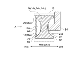
- FIG. 4 is an outer front view of the wheel as viewed from direction A in FIG. 3;
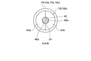
- FIG. 1 is a cross-sectional view of an amphibian wheel according to one embodiment. It is an inner front view of the wheel seen from the B direction in FIG. It is a sectional view showing the peripheral structure of the wheel concerning one embodiment. It is an outside front view of the wheel seen from the C direction in FIG. It is an inner front view of the wheel seen from the D direction in FIG. FIG.
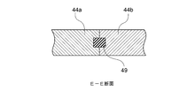
- FIG. 10 is a cross-sectional view taken along the line EE of FIG. 9; It is sectional drawing which shows the attachment structure of the wheel cover to the wheel which concerns on one Embodiment. It is the graph which compared the resistance of the water of one embodiment and a comparative example.
- expressions that indicate that things such as “identical”, “equal” and “homogeneous” are equal states not only represent strictly equal states, but also have tolerances or differences with which the same function can be obtained. It also represents the existing state.
- expressions representing shapes such as quadrilateral shapes and cylindrical shapes not only represent shapes such as rectangular shapes and cylindrical shapes in a geometrically strict sense, but also uneven portions and chamfers within the range where the same effect can be obtained. The shape including a part etc. shall also be expressed.
- the expressions “comprising”, “having”, “having”, “including” or “having” one component are not exclusive expressions excluding the presence of other components.
- FIG. 1 is a side view of an amphibian according to one embodiment.
- Figure 2 is a rear view of the amphibian of Figure 1;
- the amphibian 10 includes a vehicle body 12, a plurality of wheels 14 on each side of the vehicle body 12, and a track 16 surrounding the wheels 14. .
- the vehicle body 12 may be provided with a front flap 20 and a rear flap 22 at the front part and the rear part of the vehicle body 12, respectively.
- the amphibious vehicle 10 can obtain lift by the front flap 20 and the rear flap 22 during waterborne navigation, thereby reducing the area of the submerged portion of the vehicle body 12 and reducing the water resistance to the vehicle body 12 can do.
- each vehicle body side cover 50 may be provided on both sides of the vehicle body 12.
- each vehicle body side cover 50 has a gap with respect to the wheel 14 and the crawler belt 16 so as to cover the outer side surface of the crawler belt 16 in the vehicle body width direction. It is provided outside in the width direction.
- a plurality of wheels 14 is rotatably supported by the vehicle body 12 via a suspension 24 (see FIG. 2) described later.
- a plurality of wheels 14 includes an activation wheel 14a for rotating the crawler belt 16, a guide wheel 14b provided on the opposite side of the activation wheel 14a to enable smooth rotation of the crawler belt 16, and an activation wheel It may be located between 14a and the guide wheel 14b, and may include a wheel 14c that defines the activation of the track 16.
- the activation wheel 14 a is provided on the front side of the vehicle body 12
- the guide wheel 14 b is provided on the rear side of the vehicle body 12.
- the amphibian 10 can travel on land by transmitting power from a power source (not shown) to the activation wheel 14a and rotating the crawler belt 16 via the activation wheel 14a.
- the amphibious vehicle 10 is provided with propulsion devices such as a water jet and a propeller, and can be navigated on the water by using this propulsion device.
- the amphibious vehicle 10 Since the amphibious vehicle 10 is premised on land traveling as described above, it has a configuration in which the plurality of wheels 14 are supported by the vehicle body 12 via the suspension 24. Both side surfaces of the wheel 14 have a complicated uneven shape around the connection between the central portion of the wheel 14 and the suspension 24. For this reason, in the amphibious vehicle 10 equipped with the crawler belt 16, when traveling on the water, the crawler belt 16 is submerged and travels, so the resistance due to the uneven shape of each wheel 14 increases, and the propulsion performance on water decreases Resulting in. Even when the amphibious vehicle 10 has the vehicle body side cover 50, the vehicle body side cover 50 is limited in size in the longitudinal direction and height direction of the vehicle, so the wheel 14 surrounded by the crawler belt 16 is It is difficult to completely prevent water flow collisions.
- the amphibian 10 further includes a wheel cover that covers the sides of at least one wheel 14.
- the wheel cover described below may be made of metal or resin (for example, fiber reinforced plastic such as CFRP or GFRP). When a resin wheel cover is used, the weight of the wheel cover can be reduced.
- FIG. 3 is a cross-sectional view showing the configuration of a wheel with an outer wheel cover attached.
- FIG. 4 is a view of the wheel of FIG. 3 as viewed from the A direction.
- FIG. 5 is a cross-sectional view showing the configuration of a wheel with an inner wheel cover attached.
- FIG. 6 is a view of the wheel of FIG. 5 as viewed from the B direction.
- the amphibian 10 includes a wheel cover 18 (outer wheel cover 18 a) attached to the wheel 14 so as to cover the side of the wheel 14.
- the outer wheel cover 18 a is attached to the outside of the wheel 14 in the vehicle width direction. That is, the outer wheel cover 18a is attached to the side of the wheel 14 far from the center line L (see FIG. 2) of the vehicle body 12 in the width direction.
- the connecting portion 24 a between the central portion of the wheel 14 and the suspension 24 is covered by the outer wheel cover 18 a, and the resistance due to the complicated uneven shape of the wheel 14 around the connecting portion 24 can be reduced.
- the outer wheel cover 18a is a surface of the outer end face (outer end face) 60 in the vehicle width direction among the end faces (60, 62) of the wheel 14 and the surface of the outer wheel cover 18a.
- the position with (the outer surface) 64 is aligned.
- the surface 64 of the outer wheel cover 18a itself is a flat surface. In this case, a flat surface is formed by the outer end surface 60 of the wheel 14 and the surface 64 of the outer wheel cover 18a, and the installation of the outer wheel cover 18a can effectively reduce the on-water resistance of the amphibious vehicle 10.
- the central portion of the wheel 14 is recessed with respect to the outer end surface 60, and a recess 70 is formed on the radially inner side of the outer end surface 60.
- the outer wheel cover 18 a may be fitted into the recess 70.
- the amphibian 10 includes an inner wheel cover 18b attached to the inside of the wheel 14 in the vehicle width direction in addition to the outer wheel cover 18a.
- the amphibian 10 includes an inner wheel cover 18b instead of the outer wheel cover 18a (ie, only the inner wheel cover 18b is attached to the wheel 14).
- the inner wheel cover 18 b is attached to the wheel 14 so as to cover the inner side surface of the wheel 14 in the vehicle width direction. That is, the inner wheel cover 18b is attached to the side of the wheel 14 closer to the center line L (see FIG. 2) of the vehicle body 12 in the width direction. As a result, the connecting portion 24a between the central portion of the wheel 14 and the suspension 24 is covered by the inner wheel cover 18b, and the resistance due to the complicated uneven shape of the wheel 14 around the connecting portion 24a can be reduced.
- the inner wheel cover 18b is a surface of the inner end face (inner end face) 62 in the vehicle width direction among the both end faces (60, 62) of the wheel 14 and the surface of the inner wheel cover 18b.
- the position with (the outer surface) 66 is aligned.
- the surface 66 itself of the inner wheel cover 18b is a flat surface. In this case, a flat surface is formed by the inner end face 62 of the wheel 14 and the surface 66 of the inner wheel cover 18b, and the installation of the inner wheel cover 18b can effectively reduce the on-water resistance of the amphibian 10.
- the central portion of the wheel 14 is recessed with respect to the inner end surface 62, and a recess 72 is formed on the inner side in the radial direction of the inner end surface 62.
- the inner wheel cover 18 b may be fitted into the recess 72.
- a through hole 42 through which the suspension 24 can pass is provided at the center of the inner wheel cover 18b.
- the inner wheel cover 18 b can be attached to the inside of the wheel 14 while avoiding the interference between the inner wheel cover 18 b and the suspension 24.
- corrugated shape inside the wheel 14 can be suppressed.
- the inner wheel cover 18b has a split structure including a first cover section 44a and a second cover section 44b.
- a semicircular recess 46a is formed on the inner peripheral side of the first cover section 44a.
- a semicircular recess 46b is formed on the inner peripheral side of the second cover section 44b.
- the inner wheel cover 18b is formed by combining the pair of cover sections 44a and 44b.
- the recesses 46a and 46b of the cover sections 44a and 44b are combined to form a through hole 42 for the suspension 24 to pass through.
- the inner wheel cover 18b having the through holes 42 through which the suspension 24 passes is divided, it is possible to realize the inner wheel cover 18b capable of avoiding interference with the suspension 24 simply and at low cost.
- the wheel cover 18 (18a, 18b) described above with reference to FIGS. 3 to 6 may be attached to at least one of the drive wheel 14a or the guide wheel 14b among the plurality of wheels 14.
- the wheel covers 18 (18a, 18b) described above are attached to all the wheels 14.
- the driving wheel 14a and the guiding wheel 14b have a more complicated uneven shape on the side as compared with the rotating wheel 14c.
- the wheel cover 18 (18a, 18b) to at least one of the drive wheel 14a or the guide wheel 14b among the plurality of wheels 14, the collision of the water flow to the drive wheel 14a and the guide wheel 14b Can be suppressed, and the propulsion performance of the amphibian 10 can be improved.
- the amphibian 10 is configured to use the wheel covers 18 (18a, 18b) to form a watertight space Sw and provide the wheel 14 with buoyancy by the watertight space Sw.
- the water-tight space Sw is a space surrounded by the inner surface of the wheel cover 18 (18a, 18b) and the wall surface of the recess (70, 72) of the wheel 14 facing the inner surface.
- seal portions 26 may be provided between the wheel cover 18 (18a, 18b) and the wheel 14.
- the seal portion 26 is configured to form a watertight space Sw between the wheel cover 18 and the wheel.
- the wheel 14 functions as a buoyant body, and the volume of the submerged portion of the vehicle body 12 can be reduced.
- the resistance of water to the vehicle body 12 can be reduced, so that the propulsion performance of the amphibian 10 can be improved.
- the specific configuration of the seal portion 26 (26a, 26b) will be described in detail later.
- the amphibian 10 includes an inner peripheral edge of the through hole 42 of the inner wheel cover 18 b and a suspension 24 as shown in FIG. 5 in order to form a watertight space Sw between the inner wheel cover 18 b and the wheel 14.
- the third packing 26 c may be further included to fill the gap between the two. By filling the gap between the inner wheel cover 18b and the suspension 24 with the third packing 26c, the watertight space Sw can be made between the wheel 14 and the inner wheel cover 18b.
- the buoyancy of the vehicle body 12 can be increased by the watertight space Sw, and the volume of the submerged portion of the vehicle body 12 can be reduced, so that the water resistance to the vehicle body 12 can be reduced, and the propulsion performance of the amphibious vehicle 10 can be improved.
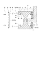
- FIG. 7 is a cross-sectional view showing a peripheral structure of a wheel according to an embodiment.
- FIG. 8 is a view on arrow C of FIG.
- FIG. 9 is a view on arrow D of FIG. 7.
- FIG. 10 is a cross-sectional view taken along the line EE of FIG.
- FIG. 11 is a view showing a mounting structure of a wheel cover on a wheel according to an embodiment.
- attachment of the wheel cover 18 (18a, 18b) to the wheel 14 is performed using a fastening member 40.
- 7 and 11 show an example in which a bolt is used as the fastening member 40.
- the wheel 14 includes a rim portion 15 forming an outer peripheral surface 80 and both end surfaces 60 and 62 of the wheel 14, and an inward flange portion 32 projecting radially inward from the rim portion 15.
- an annular coupling portion 34 is provided on the inner peripheral side of the inward flange portion 32.
- the end face of the annular coupling portion 34 is a flat surface for contacting the wheel cover 18.
- the coupling portion 34 is provided with a plurality of bolt holes 35 in the circumferential direction.
- a plurality of through holes 38 are provided in the wheel cover 18 (18a, 18b) corresponding to the intervals between the bolt holes 35 adjacent in the circumferential direction (see FIGS. 8 and 9).
- the plurality of bolts 40 respectively pass through the through holes 38 of the wheel cover 18 (18a, 18b) and are screwed into the bolt holes 35 of the joint portion 34 of the wheel 14.
- the wheel cover 18 (18a, 18b) is fastened to the wheel 14 by the bolt 40, so that the wheel cover 18 (18a, 18b) can be prevented from coming off the wheel 14.
- the head of the bolt 40 may be fitted into a recess 41 provided in the wheel cover 18 (18a, 18b). In this case, since the head of the bolt 40 does not protrude from the outer surface 64, 66 of the wheel cover 18 (18a, 18b), the resistance caused by the bolt 40 can be reduced.
- the seal 26 (26a, 26b) includes an annular first packing 28 provided on the outer peripheral edge of the wheel cover 18 (18a, 18b).
- the first packing 28 may be a rubber packing (elastic packing), and may be attached to the outer peripheral edge of the wheel cover 18 (18a, 18b) by vulcanization bonding.
- the first packing 28 is received in a groove 30 formed on the inner peripheral surface of the rim portion 15 of the wheel 14.
- the groove 30 is an outer peripheral edge of the wheel cover 18 (18a, 18b) coupled by a bolt 40 to the coupling portion 34 of the inward flange portion 32 on the side far from the widthwise center of the wheel 14 with respect to the inward flange portion 32.
- the first packing 28 provided at the position is provided in such a position as to be fitted into the groove 30.
- the seal 26 (26a, 26b) is between the inward flange 32 of the wheel 14 and the wheel cover 18 (18a, 18b).
- a second packing 36 is included to close the gap c (see FIG. 11).
- the second packing 36 is fitted in a recess 33 provided on the surface of the inward flange portion 32 facing the wheel cover 18 (18 a, 18 b).
- the second packing 36 is annularly provided on the outer peripheral side of the bolt 40.
- a recess is formed in the surface of the wheel cover 18 facing the recess 33, and the second recess
- the packing 36 may be filled.
- the third packing 26 c described above with reference to FIG. 5 is provided between the inner peripheral edge of the through hole 42 of the inner wheel cover 18 b and the suspension 24.
- the first packing 28, the second packing 36 and the third packing 48 it is possible to reliably form the watertight space Sw between the wheel cover 18 (18a, 18b) and the wheel 14. it can.
- recesses are respectively formed on the contact surfaces where the first cover section 44a and the second cover section 44b constituting the inner wheel cover 18b abut, and these recesses Packing 49 is filled.
- the inner wheel cover 18b has a divided structure, it is possible to prevent water from entering the watertight space Sw via the contact surface between the first cover section 44a and the second cover section 44b.
- the foregoing has described an amphibian 10 according to some embodiments of the present invention.
- the wheel cover 18 (18a, 18b) is provided on the outer side or the inner side of at least one wheel 14, the disturbance of the water flow generated by the uneven shape of the side surface of the wheel 14 The occurrence can be suppressed.
- the resistance which the amphibious vehicle 10 receives from water can be reduced, and the propulsion performance can be improved.
- FIG. 12 is a graph showing the relationship between the boat speed of the amphibious vehicle 10 and the water resistance according to the present embodiment.
- FIG. 12 also shows the resistance of water when only the vehicle body side cover 50 is provided as a comparative example. As shown to the same figure, in the Example, the resistance reduction effect superior to the comparative example was shown.
- the amphibian 10 according to the embodiment includes both the wheel cover 18 and the vehicle body side cover 50, so that the collision of the water flow to the wheel 14 is suppressed by the vehicle body side cover 50 while the wheel 14 is temporarily used. It is considered that the occurrence of disturbance by the wheel 14 can be suppressed by the wheel cover 18 (18a, 18b) even if the water stream collides.
Landscapes
- Engineering & Computer Science (AREA)
- Chemical & Material Sciences (AREA)
- Combustion & Propulsion (AREA)
- Transportation (AREA)
- Mechanical Engineering (AREA)
- Body Structure For Vehicles (AREA)
- Vehicle Body Suspensions (AREA)
- Arrangement Or Mounting Of Propulsion Units For Vehicles (AREA)
Abstract
幾つかの実施形態に係る水陸両用車は、車体と、前記車体の両側にそれぞれ設けられる複数のホイールと、前記複数のホイールを囲むように、前記車体の両側にそれぞれ設けられる履帯と、前記複数のホイールの少なくとも一つのホイールの外側又は内側に取り付けられ、前記ホイールの側面を覆う1以上のホイールカバーと、を備える。
Description
本開示は、水陸両用車に関する。
従来から、水陸両用車の水上抵抗を低減するための試みがなされている。
例えば、特許文献1には、履帯を備えたものではないが、水中又は水上を航行する際、車体の両側面に設けられた側面カバーにより、車輪の上側部分を覆うようにした水陸両用車が開示されている。
また、特許文献1には、無限軌道を備えた水陸両用車において、軽量材料により形成したブロックを履帯に多数取り付けることで履帯を浮力体として機能させるようにした構成が開示されている。
例えば、特許文献1には、履帯を備えたものではないが、水中又は水上を航行する際、車体の両側面に設けられた側面カバーにより、車輪の上側部分を覆うようにした水陸両用車が開示されている。
また、特許文献1には、無限軌道を備えた水陸両用車において、軽量材料により形成したブロックを履帯に多数取り付けることで履帯を浮力体として機能させるようにした構成が開示されている。
ところで、履帯を備えた水陸両用車では、履帯によって囲まれたホイール(例えば、起動輪、転輪、誘導輪等)は、ホイールの中心部と懸架との接続部周辺において凹凸が存在する。このため、履帯を備えた水陸両用車では、ホイールの凹凸形状に起因した抵抗が発生し、この抵抗が、水陸両用車の水上における推進性能低下の原因となり得る。
この点、特許文献1には、履帯を備えない水陸両用車において、車輪や浮力体に水流がぶつかることを避けるために、車体の両側面に設けた側面カバーにより車輪の上側部分を覆うことが開示されている。
しかしながら、履帯を備えた水陸両用車に特許文献1記載の側面カバーを適用しても、側面カバーには車体前後方向および高さ方向にサイズの制約が存在するため、履帯によって囲まれたホイールへの水流の衝突を完全に阻止することは困難である。ホイールに水流が衝突すると、水流が乱れて抵抗が増加する。
しかしながら、履帯を備えた水陸両用車に特許文献1記載の側面カバーを適用しても、側面カバーには車体前後方向および高さ方向にサイズの制約が存在するため、履帯によって囲まれたホイールへの水流の衝突を完全に阻止することは困難である。ホイールに水流が衝突すると、水流が乱れて抵抗が増加する。
また、特許文献2には、履帯を備えた水陸両用車が水から受ける抵抗を低減するための構成が開示されていない。
上記課題に鑑み、本発明の幾つかの実施形態は、履帯に囲まれたホイールによる水流の乱れの発生を抑制することが可能な水陸両用車を提供することを目的とする。
(1)幾つかの実施形態に係る水陸両用車は、
車体と、
前記車体の両側にそれぞれ設けられる複数のホイールと、
前記複数のホイールを囲むように、前記車体の両側にそれぞれ設けられる履帯と、
前記複数のホイールの少なくとも一つのホイールの外側又は内側に取り付けられ、前記ホイールの側面を覆う1以上のホイールカバーと、
を備える。
上記(1)の構成によれば、上記複数のホイールの少なくとも一つのホイールの外側又は内側に上記ホイールカバーを備えることで、ホイール側面の凹凸形状によって発生する水流の乱れの発生を抑制できる。これによって、水陸両用車が水から受ける抵抗を低減でき、推進性能を向上させることができる。
なお、本明細書において、ホイールの「外側」とは、ホイールのうち、幅方向における車体の中心線から遠い側を指す。一方、ホイールの「内側」とは、ホイールのうち、幅方向における車体の中心線に近い側を指す。
車体と、
前記車体の両側にそれぞれ設けられる複数のホイールと、
前記複数のホイールを囲むように、前記車体の両側にそれぞれ設けられる履帯と、
前記複数のホイールの少なくとも一つのホイールの外側又は内側に取り付けられ、前記ホイールの側面を覆う1以上のホイールカバーと、
を備える。
上記(1)の構成によれば、上記複数のホイールの少なくとも一つのホイールの外側又は内側に上記ホイールカバーを備えることで、ホイール側面の凹凸形状によって発生する水流の乱れの発生を抑制できる。これによって、水陸両用車が水から受ける抵抗を低減でき、推進性能を向上させることができる。
なお、本明細書において、ホイールの「外側」とは、ホイールのうち、幅方向における車体の中心線から遠い側を指す。一方、ホイールの「内側」とは、ホイールのうち、幅方向における車体の中心線に近い側を指す。
(2)幾つかの実施形態では、前記(1)の構成において、
前記ホイールカバーの外表面は平坦面である。
上記(2)の構成によれば、上記ホイールカバーの外表面を平坦面としたので、ホイール付近の水流の乱れを効果的に抑制でき、これによって、推進性能を効果的に向上させることができる。
前記ホイールカバーの外表面は平坦面である。
上記(2)の構成によれば、上記ホイールカバーの外表面を平坦面としたので、ホイール付近の水流の乱れを効果的に抑制でき、これによって、推進性能を効果的に向上させることができる。
(3)幾つかの実施形態では、前記(1)又は(2)の構成において、
前記ホイールを前記車体に支持する懸架をさらに備え、
前記ホイールカバーは、前記少なくとも一つの前記ホイールと前記懸架との接続部を覆うように設けられる。
上記(3)の構成によれば、ホイールカバーによってホイールと上記懸架との接続部を覆うことで、上記接続部の複雑な形状に起因して発生する水流の乱れを抑制できる。これによって、水陸両用車の推進性能を効果的に向上させることができる。
前記ホイールを前記車体に支持する懸架をさらに備え、
前記ホイールカバーは、前記少なくとも一つの前記ホイールと前記懸架との接続部を覆うように設けられる。
上記(3)の構成によれば、ホイールカバーによってホイールと上記懸架との接続部を覆うことで、上記接続部の複雑な形状に起因して発生する水流の乱れを抑制できる。これによって、水陸両用車の推進性能を効果的に向上させることができる。
(4)幾つかの実施形態では、前記(1)~(3)の何れかの構成において、
前記ホイールカバーは、前記複数のホイールのうち起動輪又は誘導輪の少なくとも一方に取り付けられる。
水陸両用車に設けられるホイールのうち、起動輪及び誘導輪は転輪などと比べて側面はさらに複雑な凹凸形状を有している。
上記(4)の構成によれば、起動輪及び誘導輪にホイールカバーを取り付けることで、起動輪及び誘導輪への水流の衝突によって生じる乱れを抑制し、水陸両用車の推進性能を向上させることができる。
前記ホイールカバーは、前記複数のホイールのうち起動輪又は誘導輪の少なくとも一方に取り付けられる。
水陸両用車に設けられるホイールのうち、起動輪及び誘導輪は転輪などと比べて側面はさらに複雑な凹凸形状を有している。
上記(4)の構成によれば、起動輪及び誘導輪にホイールカバーを取り付けることで、起動輪及び誘導輪への水流の衝突によって生じる乱れを抑制し、水陸両用車の推進性能を向上させることができる。
(5)幾つかの実施形態では、前記(1)~(4)の何れかの構成において、
前記少なくとも一つの前記ホイールと前記ホイールカバーとの間に設けられたシール部をさらに備え、前記シール部によって、前記ホイールカバーと前記ホイールとの間に水密な空間が形成される。
上記(5)の構成によれば、ホイールカバーとホイール表面との間に水密空間を形成することで、ホイールが浮力体として機能し、車体の水没部の体積を減少できる。これによって、車体に対する水の抵抗を低減できるため、推進性能を向上できる。
前記少なくとも一つの前記ホイールと前記ホイールカバーとの間に設けられたシール部をさらに備え、前記シール部によって、前記ホイールカバーと前記ホイールとの間に水密な空間が形成される。
上記(5)の構成によれば、ホイールカバーとホイール表面との間に水密空間を形成することで、ホイールが浮力体として機能し、車体の水没部の体積を減少できる。これによって、車体に対する水の抵抗を低減できるため、推進性能を向上できる。
(6)幾つかの実施形態では、前記(5)の構成において、
前記シール部は、前記ホイールカバーの外周縁に設けられた第1パッキンを含み、
前記少なくとも一つの前記ホイールは、前記ホイールカバーの外周縁に設けられた前記第1パッキンを受け入れる溝を有する。
上記(6)の構成によれば、ホイールカバーとホイールとの間に形成される上記水密空間を、上記第1パッキン及び上記溝で構成される上記シール部によって簡易かつ低コストで実現できる。
前記シール部は、前記ホイールカバーの外周縁に設けられた第1パッキンを含み、
前記少なくとも一つの前記ホイールは、前記ホイールカバーの外周縁に設けられた前記第1パッキンを受け入れる溝を有する。
上記(6)の構成によれば、ホイールカバーとホイールとの間に形成される上記水密空間を、上記第1パッキン及び上記溝で構成される上記シール部によって簡易かつ低コストで実現できる。
(7)幾つかの実施形態では、前記(5)又は(6)の構成において、
前記少なくとも一つのホイールは、
リム部と、
前記リム部から前記ホイールの径方向内側に突出する内向きフランジ部と、
を含み、
前記シール部は、前記ホイールの前記内向きフランジ部と前記ホイールカバーとの間の隙間を塞ぐ第2パッキンを含む。
上記(7)の構成によれば、上記シール部は、上記内向きフランジ部とホイールカバーとの間の隙間を上記第2パッキンで塞ぐことで、さらに水密性能を向上できる。
前記少なくとも一つのホイールは、
リム部と、
前記リム部から前記ホイールの径方向内側に突出する内向きフランジ部と、
を含み、
前記シール部は、前記ホイールの前記内向きフランジ部と前記ホイールカバーとの間の隙間を塞ぐ第2パッキンを含む。
上記(7)の構成によれば、上記シール部は、上記内向きフランジ部とホイールカバーとの間の隙間を上記第2パッキンで塞ぐことで、さらに水密性能を向上できる。
(8)幾つかの実施形態では、前記(1)~(7)の何れかの構成において、
前記ホイールを前記車体に支持する懸架をさらに備え、
前記1以上のホイールカバーは、前記ホイールの内側に取り付けられる内側ホイールカバーを含み、
前記内側ホイールカバーは、前記懸架が貫通する貫通孔を有する。
上記(8)の構成によれば、懸架が貫通する貫通孔を内側ホイールカバーに設けたので、内側ホイールカバーと懸架との干渉を回避しながら、ホイールの内側にホイールカバー(内側ホイールカバー)を取り付けることができる。これによって、ホイールの内側の凹凸形状による水流の乱れの発生を抑制できる。
前記ホイールを前記車体に支持する懸架をさらに備え、
前記1以上のホイールカバーは、前記ホイールの内側に取り付けられる内側ホイールカバーを含み、
前記内側ホイールカバーは、前記懸架が貫通する貫通孔を有する。
上記(8)の構成によれば、懸架が貫通する貫通孔を内側ホイールカバーに設けたので、内側ホイールカバーと懸架との干渉を回避しながら、ホイールの内側にホイールカバー(内側ホイールカバー)を取り付けることができる。これによって、ホイールの内側の凹凸形状による水流の乱れの発生を抑制できる。
(9)幾つかの実施形態では、前記(8)の構成において、
前記内側ホイールカバーは、
第1凹部を有する第1カバーセクションと、
第2凹部を有する第2カバーセクションと、
を含む分割構造を有し、
前記第1凹部及び前記第2凹部によって、前記貫通孔が形成される。
上記(9)の構成によれば、内側ホイールカバーは上記分割構造を有し、上記第1凹部及び上記第2凹部によって上記貫通孔を形成するため、簡易かつ低コストで、懸架との干渉を回避可能な内側ホイールカバーを形成できる。
前記内側ホイールカバーは、
第1凹部を有する第1カバーセクションと、
第2凹部を有する第2カバーセクションと、
を含む分割構造を有し、
前記第1凹部及び前記第2凹部によって、前記貫通孔が形成される。
上記(9)の構成によれば、内側ホイールカバーは上記分割構造を有し、上記第1凹部及び上記第2凹部によって上記貫通孔を形成するため、簡易かつ低コストで、懸架との干渉を回避可能な内側ホイールカバーを形成できる。
(10)幾つかの実施形態では、前記(8)又は(9)の構成において、
前記内側ホイールカバーの前記貫通孔の内周縁と前記懸架との間の隙間を埋めるための第3パッキンを備える。
上記(10)の構成によれば、上記第3パッキンによって内側ホイールカバーと懸架との間の隙間を埋めることで、ホイールと内側ホイールカバーとの間を水密空間とすることができる。これによって、車体の浮力を増加でき、車体の水没部の体積を減少できるため、車体に対する水の抵抗を低減でき、推進性能を向上できる。
前記内側ホイールカバーの前記貫通孔の内周縁と前記懸架との間の隙間を埋めるための第3パッキンを備える。
上記(10)の構成によれば、上記第3パッキンによって内側ホイールカバーと懸架との間の隙間を埋めることで、ホイールと内側ホイールカバーとの間を水密空間とすることができる。これによって、車体の浮力を増加でき、車体の水没部の体積を減少できるため、車体に対する水の抵抗を低減でき、推進性能を向上できる。
(11)幾つかの実施形態では、前記(1)~(10)の何れかの構成において、
前記履帯の外側の側面を覆うように、前記車体の両側に設けられた一対の車体側面カバーをさらに備える。
上記(11)の構成によれば、上記(1)で述べたホイールカバーに加えて、上記車体側面カバーをさらに備えることで、車体側面カバーによりホイールへの水流の衝突を抑制しつつ、仮にホイールに水流が衝突してもホイールによる乱れ発生をホイールカバーで抑制することができる。こうして、履帯周辺における水流の乱れ発生を効果的に抑制でき、水陸両用車の推進性能を効果的に向上させることができる。
前記履帯の外側の側面を覆うように、前記車体の両側に設けられた一対の車体側面カバーをさらに備える。
上記(11)の構成によれば、上記(1)で述べたホイールカバーに加えて、上記車体側面カバーをさらに備えることで、車体側面カバーによりホイールへの水流の衝突を抑制しつつ、仮にホイールに水流が衝突してもホイールによる乱れ発生をホイールカバーで抑制することができる。こうして、履帯周辺における水流の乱れ発生を効果的に抑制でき、水陸両用車の推進性能を効果的に向上させることができる。
本発明の少なくとも幾つかの実施形態によれば、水陸両用車の水上又は水中航行時に、水陸両用車が水から受ける抵抗を低減でき、推進性能を向上させることができる。
以下、添付図面を参照して本発明の幾つかの実施形態について説明する。ただし、実施形態として記載され又は図面に示されている構成部品の寸法、材質、形状、その相対的配置等は、本発明の範囲をこれに限定する趣旨ではなく、単なる説明例にすぎない。
例えば、「ある方向に」、「ある方向に沿って」、「平行」、「直交」、「中心」、「同心」或いは「同軸」等の相対的或いは絶対的な配置を表す表現は、厳密にそのような配置を表すのみならず、公差、若しくは、同じ機能が得られる程度の角度や距離をもって相対的に変位している状態も表すものとする。
例えば、「同一」、「等しい」及び「均質」等の物事が等しい状態であることを表す表現は、厳密に等しい状態を表すのみならず、公差、若しくは、同じ機能が得られる程度の差が存在している状態も表すものとする。
例えば、四角形状や円筒形状等の形状を表す表現は、幾何学的に厳密な意味での四角形状や円筒形状等の形状を表すのみならず、同じ効果が得られる範囲で、凹凸部や面取り部等を含む形状も表すものとする。
一方、一つの構成要素を「備える」、「具える」、「具備する」、「含む」、又は「有する」という表現は、他の構成要素の存在を除外する排他的な表現ではない。
例えば、「ある方向に」、「ある方向に沿って」、「平行」、「直交」、「中心」、「同心」或いは「同軸」等の相対的或いは絶対的な配置を表す表現は、厳密にそのような配置を表すのみならず、公差、若しくは、同じ機能が得られる程度の角度や距離をもって相対的に変位している状態も表すものとする。
例えば、「同一」、「等しい」及び「均質」等の物事が等しい状態であることを表す表現は、厳密に等しい状態を表すのみならず、公差、若しくは、同じ機能が得られる程度の差が存在している状態も表すものとする。
例えば、四角形状や円筒形状等の形状を表す表現は、幾何学的に厳密な意味での四角形状や円筒形状等の形状を表すのみならず、同じ効果が得られる範囲で、凹凸部や面取り部等を含む形状も表すものとする。
一方、一つの構成要素を「備える」、「具える」、「具備する」、「含む」、又は「有する」という表現は、他の構成要素の存在を除外する排他的な表現ではない。
はじめに、図1及び図2を参照して、水陸両用車の全体構成について説明する。図1は、一実施形態に係る水陸両用車の側面図である。図2は、図1に示す水陸両用車の背面図である。
図1及び2に示すように、幾つかの実施形態では、水陸両用車10は、車体12と、車体12の両側に夫々複数のホイール14と、複数のホイール14を囲む履帯16と、を備える。
車体12は、車体12の前方部及び後方部にそれぞれ前フラップ20及び後フラップ22を備えていてもよい。
この場合、水陸両用車10は、水上航行中、前フラップ20及び後フラップ22によって揚力を得ることができ、これによって、車体12の水没部の面積を減少でき、車体12に対する水の抵抗を低減することができる。
この場合、水陸両用車10は、水上航行中、前フラップ20及び後フラップ22によって揚力を得ることができ、これによって、車体12の水没部の面積を減少でき、車体12に対する水の抵抗を低減することができる。
また、車体12の両側に一対の車体側面カバー50が設けられていてもよい。この場合、各々の車体側面カバー50は、図1及び図2に示すように、履帯16の車体幅方向における外側の側面を覆うように、ホイール14及び履帯16に対して隙間を有して車体幅方向における外側に設けられる。
複数のホイール14は、それぞれ、後述する懸架24(図2参照)を介して車体12に回転自在に支持されている。
また、複数のホイール14は、履帯16を回転させるための起動輪14aと、起動輪14aとは反対側に設けられて履帯16の円滑な回転を可能とするための誘導輪14bと、起動輪14aと誘導輪14bの間に位置し、履帯16の起動を規定する転輪14cと、を含んでいてもよい。なお、図1に示す例示的な実施形態では、車体12の前方側に起動輪14aが設けられ、車体12の後方側に誘導輪14bが設けられる。
また、複数のホイール14は、履帯16を回転させるための起動輪14aと、起動輪14aとは反対側に設けられて履帯16の円滑な回転を可能とするための誘導輪14bと、起動輪14aと誘導輪14bの間に位置し、履帯16の起動を規定する転輪14cと、を含んでいてもよい。なお、図1に示す例示的な実施形態では、車体12の前方側に起動輪14aが設けられ、車体12の後方側に誘導輪14bが設けられる。
水陸両用車10は、陸上において、不図示の動力源からの動力を起動輪14aに伝えて、起動輪14aを介して履帯16を回転させることで、走行可能になっている。
また、水陸両用車10は、ウォータジェットやプロペラなどの推進装置を備えており、この推進装置を用いて水上航行可能となっている。
また、水陸両用車10は、ウォータジェットやプロペラなどの推進装置を備えており、この推進装置を用いて水上航行可能となっている。
水陸両用車10は、上述のとおり、陸上走行を前提としているため、懸架24を介して複数のホイール14が車体12に支持された構成を有する。ホイール14の両側面は、ホイール14の中心部と懸架24との接続部周辺において複雑な凹凸形状を有する。このため、履帯16を備えた水陸両用車10では、水上航行時には、履帯16が水没して航行するために、各々のホイール14の凹凸形状に起因した抵抗が増加し、水上における推進性能が低下してしまう。
なお、水陸両用車10が車体側面カバー50を有する場合であっても、車体側面カバー50には車体前後方向および高さ方向にサイズの制約が存在するため、履帯16によって囲まれたホイール14への水流の衝突を完全に阻止することは困難である。
なお、水陸両用車10が車体側面カバー50を有する場合であっても、車体側面カバー50には車体前後方向および高さ方向にサイズの制約が存在するため、履帯16によって囲まれたホイール14への水流の衝突を完全に阻止することは困難である。
そこで、幾つかの実施形態では、水陸両用車10は、少なくとも一つのホイール14の側面を覆うホイールカバーをさらに備える。なお、以下で述べるホイールカバーは、金属製であってもよいし、樹脂(例えば、CFRPやGFRPのような繊維強化プラスチック)製であってもよい。樹脂製のホイールカバーを用いる場合、ホイールカバーを軽量化することができる。
以下、図3~図6を参照して、ホイールカバーの構成について説明する。
図3は、外側ホイールカバーが取り付けられたホイールの構成を示す断面図である。図4は、図3のホイールをA方向から視た図である。図5は、内側ホイールカバーが取り付けられたホイールの構成を示す断面図である。図6は、図5のホイールをB方向から視た図である。
図3は、外側ホイールカバーが取り付けられたホイールの構成を示す断面図である。図4は、図3のホイールをA方向から視た図である。図5は、内側ホイールカバーが取り付けられたホイールの構成を示す断面図である。図6は、図5のホイールをB方向から視た図である。
図3及び図4に示す実施形態では、水陸両用車10は、ホイール14の側面を覆うようにホイール14に取り付けられるホイールカバー18(外側ホイールカバー18a)を備える。外側ホイールカバー18aは、ホイール14の車体幅方向における外側に取り付けられる。即ち、外側ホイールカバー18aは、ホイール14のうち、幅方向における車体12の中心線L(図2参照)から遠い側に取り付けられる。
これにより、ホイール14の中心部と懸架24との接続部24aは、外側ホイールカバー18aによって覆われ、接続部24周辺におけるホイール14の複雑な凹凸形状に起因した抵抗を低減することができる。
これにより、ホイール14の中心部と懸架24との接続部24aは、外側ホイールカバー18aによって覆われ、接続部24周辺におけるホイール14の複雑な凹凸形状に起因した抵抗を低減することができる。
一実施形態では、図3に示すように、外側ホイールカバー18aは、ホイール14の両端面(60,62)のうち、車体幅方向における外側の端面(外側端面)60と外側ホイールカバー18aの表面(外表面)64との位置が揃っている。また、外側ホイールカバー18aの表面64自体は平坦面である。
この場合、ホイール14の外側端面60と、外側ホイールカバー18aの表面64とで平坦面が形成され、外側ホイールカバー18aの設置により水陸両用車10の水上抵抗を効果的に低減することができる。
この場合、ホイール14の外側端面60と、外側ホイールカバー18aの表面64とで平坦面が形成され、外側ホイールカバー18aの設置により水陸両用車10の水上抵抗を効果的に低減することができる。
また、図3に示すように、ホイール14の中心部は外側端面60に対して凹んでおり、外側端面60の径方向内側には凹部70が形成されている。外側ホイールカバー18aは、この凹部70に嵌め込まれていてもよい。
ホイール14の外側端面60の径方向内側に位置する凹部70に外側ホイールカバー18aを嵌め込むことで、外側ホイールカバー18aがホイール14の径方向外側に突出することがないため、ホイール14の周囲に存在する履帯16と外側ホイールカバー18aとの干渉を回避できる。
ホイール14の外側端面60の径方向内側に位置する凹部70に外側ホイールカバー18aを嵌め込むことで、外側ホイールカバー18aがホイール14の径方向外側に突出することがないため、ホイール14の周囲に存在する履帯16と外側ホイールカバー18aとの干渉を回避できる。
図5及び図6に示す実施形態では、水陸両用車10は、外側ホイールカバー18aに加えて、ホイール14の車両幅方向における内側に取り付けられる内側ホイールカバー18bを備えている。
なお、他の実施形態では、水陸両用車10は、外側ホイールカバー18aに替えて内側ホイールカバー18bを備える(即ち、内側ホイールカバー18bのみがホイール14に取り付けられている)。
なお、他の実施形態では、水陸両用車10は、外側ホイールカバー18aに替えて内側ホイールカバー18bを備える(即ち、内側ホイールカバー18bのみがホイール14に取り付けられている)。
内側ホイールカバー18bは、ホイール14のうち車両幅方向における内側の側面を覆うようにホイール14に取り付けられる。即ち、内側ホイールカバー18bは、ホイール14のうち、幅方向における車体12の中心線L(図2参照)に近い側に取り付けられる。
これにより、ホイール14の中心部と懸架24との接続部24aは、内側ホイールカバー18bによって覆われ、接続部24a周辺におけるホイール14の複雑な凹凸形状に起因した抵抗を低減することができる。
これにより、ホイール14の中心部と懸架24との接続部24aは、内側ホイールカバー18bによって覆われ、接続部24a周辺におけるホイール14の複雑な凹凸形状に起因した抵抗を低減することができる。
一実施形態では、図5に示すように、内側ホイールカバー18bは、ホイール14の両端面(60,62)のうち、車体幅方向における内側の端面(内側端面)62と内側ホイールカバー18bの表面(外表面)66との位置が揃っている。また、内側ホイールカバー18bの表面66自体は平坦面である。
この場合、ホイール14の内側端面62と、内側ホイールカバー18bの表面66とで平坦面が形成され、内側ホイールカバー18bの設置により水陸両用車10の水上抵抗を効果的に低減することができる。
この場合、ホイール14の内側端面62と、内側ホイールカバー18bの表面66とで平坦面が形成され、内側ホイールカバー18bの設置により水陸両用車10の水上抵抗を効果的に低減することができる。
また、図5に示すように、ホイール14の中心部は内側端面62に対して凹んでおり、内側端面62の径方向内側には凹部72が形成されている。内側ホイールカバー18bは、この凹部72に嵌め込まれていてもよい。
ホイール14の内側端面62の径方向内側に位置する凹部72に内側ホイールカバー18bを嵌め込むことで、内側ホイールカバー18bがホイール14の径方向外側に突出することがないため、ホイール14の周囲に存在する履帯16と内側ホイールカバー18bとの干渉を回避できる。
ホイール14の内側端面62の径方向内側に位置する凹部72に内側ホイールカバー18bを嵌め込むことで、内側ホイールカバー18bがホイール14の径方向外側に突出することがないため、ホイール14の周囲に存在する履帯16と内側ホイールカバー18bとの干渉を回避できる。
また、図5及び図6に示す実施形態では、内側ホイールカバー18bの中央部には、懸架24が貫通可能な貫通孔42が設けられる。
このように、内側ホイールカバー18bに貫通孔42を設けることで、内側ホイールカバー18bと懸架24との干渉を回避しながら、ホイール14の内側に内側ホイールカバー18bを装着できる。これによって、ホイール14の内側の凹凸形状による水流の乱れの発生を抑制できる。
このように、内側ホイールカバー18bに貫通孔42を設けることで、内側ホイールカバー18bと懸架24との干渉を回避しながら、ホイール14の内側に内側ホイールカバー18bを装着できる。これによって、ホイール14の内側の凹凸形状による水流の乱れの発生を抑制できる。
さらに、図6に示すように、内側ホイールカバー18bは、第1カバーセクション44a及び第2カバーセクション44bを含む分割構造を有する。
第1カバーセクション44aの内周側には、半円形状の凹部46aが形成されている。一方、第2カバーセクション44bの内周側には、半円形状の凹部46bが形成されている。これら一対のカバーセクション44a,44bを合せることで、内側ホイールカバー18bが形成される。また、各々のカバーセクション44a,44bの凹部46a,46bが合わさって、懸架24が貫通するための貫通孔42が形成されるようになっている。
このように、懸架24が貫通する貫通孔42を有する内側ホイールカバー18bを分割構造にすることで、簡易かつ低コストで、懸架24との干渉を回避可能な内側ホイールカバー18bを実現できる。
第1カバーセクション44aの内周側には、半円形状の凹部46aが形成されている。一方、第2カバーセクション44bの内周側には、半円形状の凹部46bが形成されている。これら一対のカバーセクション44a,44bを合せることで、内側ホイールカバー18bが形成される。また、各々のカバーセクション44a,44bの凹部46a,46bが合わさって、懸架24が貫通するための貫通孔42が形成されるようになっている。
このように、懸架24が貫通する貫通孔42を有する内側ホイールカバー18bを分割構造にすることで、簡易かつ低コストで、懸架24との干渉を回避可能な内側ホイールカバー18bを実現できる。
なお、図3~図6を参照して上述したホイールカバー18(18a,18b)は、複数のホイール14のうち起動輪14a又は誘導輪14bの少なくとも一方に取り付けられてもよい。一実施形態では、上述のホイールカバー18(18a,18b)が、全てのホイール14に対して取り付けられる。
水陸両用車10に設けられるホイール14のうち、起動輪14a及び誘導輪14bは、転輪14cと比べて側面がさらに複雑な凹凸形状を有している。このため、上述のように、複数のホイール14のうち起動輪14a又は誘導輪14bの少なくとも一方にホイールカバー18(18a,18b)を取り付けることで、起動輪14a及び誘導輪14bへの水流の衝突によって生じる乱れを抑制し、水陸両用車10の推進性能を向上できる。
水陸両用車10に設けられるホイール14のうち、起動輪14a及び誘導輪14bは、転輪14cと比べて側面がさらに複雑な凹凸形状を有している。このため、上述のように、複数のホイール14のうち起動輪14a又は誘導輪14bの少なくとも一方にホイールカバー18(18a,18b)を取り付けることで、起動輪14a及び誘導輪14bへの水流の衝突によって生じる乱れを抑制し、水陸両用車10の推進性能を向上できる。
幾つかの実施形態では、水陸両用車10は、ホイールカバー18(18a,18b)を利用して水密空間Swを形成し、水密空間Swによってホイール14に浮力を与えるように構成される。
ここで、水密空間Swは、ホイールカバー18(18a,18b)の内表面と、該内表面に対向するホイール14の凹部(70,72)の壁面とで囲まれた空間である。
ここで、水密空間Swは、ホイールカバー18(18a,18b)の内表面と、該内表面に対向するホイール14の凹部(70,72)の壁面とで囲まれた空間である。
水密空間Swを形成するために、図3及び図5に示すように、ホイールカバー18(18a,18b)とホイール14との間にシール部26(26a,26b)を設けてもよい。シール部26は、ホイールカバー18とホイールとの間に水密空間Swを形成するように構成される。
このように、ホイールカバー18とホイール14の側面との間に水密空間Swを形成することで、ホイール14が浮力体として機能し、車体12の水没部の体積を減少できる。これによって、車体12に対する水の抵抗を低減できるため、水陸両用車10の推進性能を向上できる。なお、シール部26(26a,26b)の具体的構成については後で詳述する。
このように、ホイールカバー18とホイール14の側面との間に水密空間Swを形成することで、ホイール14が浮力体として機能し、車体12の水没部の体積を減少できる。これによって、車体12に対する水の抵抗を低減できるため、水陸両用車10の推進性能を向上できる。なお、シール部26(26a,26b)の具体的構成については後で詳述する。
また、内側ホイールカバー18bとホイール14との間に水密空間Swを形成するために、図5に示すように、水陸両用車10は、内側ホイールカバー18bの貫通孔42の内周縁と懸架24との間の隙間を埋めるための第3パッキン26cをさらに備えてもよい。
上記第3パッキン26cによって内側ホイールカバー18bと懸架24との間の隙間を埋めることで、ホイール14と内側ホイールカバー18bとの間を水密空間Swとすることができる。こうして、水密空間Swにより車体12の浮力を増加でき、車体12の水没部の体積を減少できるため、車体12に対する水の抵抗を低減でき、水陸両用車10の推進性能を向上できる。
上記第3パッキン26cによって内側ホイールカバー18bと懸架24との間の隙間を埋めることで、ホイール14と内側ホイールカバー18bとの間を水密空間Swとすることができる。こうして、水密空間Swにより車体12の浮力を増加でき、車体12の水没部の体積を減少できるため、車体12に対する水の抵抗を低減でき、水陸両用車10の推進性能を向上できる。
続いて、図7~図11を参照して、ホイール14へのホイールカバー18(18a,18b)の取付構造及びシール部26(26a,26b)の構造について説明する。
図7は、一実施形態に係るホイールの周辺構造を示す断面図である。図8は、図7のC矢視図である。図9は、図7のD矢視図である。図10は、図9のE-E断面図である。図11は、一実施形態に係るホイールへのホイールカバーの取付構造を示す図である。
図7は、一実施形態に係るホイールの周辺構造を示す断面図である。図8は、図7のC矢視図である。図9は、図7のD矢視図である。図10は、図9のE-E断面図である。図11は、一実施形態に係るホイールへのホイールカバーの取付構造を示す図である。
図7及び図11に示すように、幾つかの実施形態では、ホイール14へのホイールカバー18(18a,18b)の取付けは、締結部材40を用いて行われる。なお、図7及び図11には、締結部材40としてボルトを用いた例を示している。
具体的には、ホイール14は、ホイール14の外周面80及び両端面60,62を形成するリム部15と、リム部15から径方向内側に突出する内向きフランジ部32と、を含む。内向きフランジ部32の内周側には、図7に示すように、環状の結合部34が設けられている。環状の結合部34の端面はホイールカバー18に当接するための平坦面となっている。結合部34には、周方向に複数のボルト穴35が設けられている。周方向に隣り合うボルト穴35の間隔に対応して、ホイールカバー18(18a,18b)には複数の貫通孔38が設けられている(図8及び図9参照)。複数のボルト40は、それぞれ、ホイールカバー18(18a,18b)の貫通孔38を貫通するとともに、ホイール14の結合部34のボルト穴35にねじ込まれる。こうして、ホイールカバー18(18a,18b)は、ボルト40によってホイール14に締結されるので、ホイールカバー18(18a,18b)のホイール14からの脱落を防止できる。
具体的には、ホイール14は、ホイール14の外周面80及び両端面60,62を形成するリム部15と、リム部15から径方向内側に突出する内向きフランジ部32と、を含む。内向きフランジ部32の内周側には、図7に示すように、環状の結合部34が設けられている。環状の結合部34の端面はホイールカバー18に当接するための平坦面となっている。結合部34には、周方向に複数のボルト穴35が設けられている。周方向に隣り合うボルト穴35の間隔に対応して、ホイールカバー18(18a,18b)には複数の貫通孔38が設けられている(図8及び図9参照)。複数のボルト40は、それぞれ、ホイールカバー18(18a,18b)の貫通孔38を貫通するとともに、ホイール14の結合部34のボルト穴35にねじ込まれる。こうして、ホイールカバー18(18a,18b)は、ボルト40によってホイール14に締結されるので、ホイールカバー18(18a,18b)のホイール14からの脱落を防止できる。
なお、ボルト40の頭部は、ホイールカバー18(18a,18b)に設けた凹部41に嵌り込むようになっていてもよい。この場合、ホイールカバー18(18a,18b)の外表面64,66からボルト40の頭部が突出しないので、ボルト40に起因した抵抗を低減できる。
幾つかの実施形態では、図7及び図11に示すように、シール部26(26a、26b)はホイールカバー18(18a、18b)の外周縁に設けられた環状の第1パッキン28を含む。第1パッキン28は、ゴムパッキン(弾性パッキン)であってもよく、ホイールカバー18(18a、18b)の外周縁に対して加硫接合により取り付けてもよい。
第1パッキン28は、ホイール14のリム部15の内周面に形成された溝30に受け入れられる。溝30は、内向きフランジ部32に対してホイール14の幅方向中心から遠い側において、内向きフランジ部32の結合部34にボルト40によって結合されたホイールカバー18(18a,18b)の外周縁に設けられた第1パッキン28が溝30に嵌り込むような位置に設けられる。
これにより、第1パッキン28を用いて、ホイールカバー18(18a,18b)とホイール14との間に形成される水密空間Swを簡易かつ低コストで実現できる。
第1パッキン28は、ホイール14のリム部15の内周面に形成された溝30に受け入れられる。溝30は、内向きフランジ部32に対してホイール14の幅方向中心から遠い側において、内向きフランジ部32の結合部34にボルト40によって結合されたホイールカバー18(18a,18b)の外周縁に設けられた第1パッキン28が溝30に嵌り込むような位置に設けられる。
これにより、第1パッキン28を用いて、ホイールカバー18(18a,18b)とホイール14との間に形成される水密空間Swを簡易かつ低コストで実現できる。
また、幾つかの実施形態では、図7及び図11に示すように、シール部26(26a,26b)は、ホイール14の内向きフランジ部32とホイールカバー18(18a,18b)との間の隙間c(図11参照)を塞ぐ第2パッキン36を含む。
図7及び図11に示す例では、第2パッキン36は、内向きフランジ部32のホイールカバー18(18a,18b)に対向する面に設けられた凹部33に嵌め込まれている。第2パッキン36は、ボルト40の外周側において、環状に設けられている。内向きフランジ部32とホイールカバー18(18a,18b)との間の隙間cを第2パッキン36で塞ぐことで、さらに水密性能を向上できる。
なお、他の実施形態において、内向きフランジ部32に凹部33を形成する代わりに、又は凹部33に加えて、凹部33と対面するホイールカバー18の面に凹部を形成し、この凹部に第2パッキン36を充填するようにしてもよい。
図7及び図11に示す例では、第2パッキン36は、内向きフランジ部32のホイールカバー18(18a,18b)に対向する面に設けられた凹部33に嵌め込まれている。第2パッキン36は、ボルト40の外周側において、環状に設けられている。内向きフランジ部32とホイールカバー18(18a,18b)との間の隙間cを第2パッキン36で塞ぐことで、さらに水密性能を向上できる。
なお、他の実施形態において、内向きフランジ部32に凹部33を形成する代わりに、又は凹部33に加えて、凹部33と対面するホイールカバー18の面に凹部を形成し、この凹部に第2パッキン36を充填するようにしてもよい。
なお、内側ホイールカバー18bの貫通孔42の内周縁と懸架24との間には、図5を参照して上述した第3パッキン26cが設けられている。
以上述べたように、第1パッキン28,第2パッキン36及び第3パッキン48を用いることで、ホイールカバー18(18a,18b)とホイール14との間に水密空間Swを確実に形成することができる。
また、図9及び図10に示す実施形態では、内側ホイールカバー18bを構成する第1カバーセクション44aと第2カバーセクション44bとが当接する当接面には、夫々凹部が形成され、これらの凹部にパッキン49が充填される。
これによって、内側ホイールカバー18bが分割構造である場合においても、第1カバーセクション44aと第2カバーセクション44bとの当接面を介した水密空間Swへの水の侵入を阻止できる。
これによって、内側ホイールカバー18bが分割構造である場合においても、第1カバーセクション44aと第2カバーセクション44bとの当接面を介した水密空間Swへの水の侵入を阻止できる。
以上、本発明の幾つかの実施形態に係る水陸両用車10について述べた。上述の実施形態に係る水陸両用車10によれば、少なくとも一つのホイール14の外側又は内側にホイールカバー18(18a,18b)を設けたので、ホイール14側面の凹凸形状によって発生する水流の乱れの発生を抑制できる。これによって、水陸両用車10が水から受ける抵抗を低減でき、推進性能を向上させることができる。
図12は、本実施形態に係る水陸両用車10の船速と水の抵抗との関係を示すグラフである。図12において、比較例として、車体側面カバー50のみを設けた場合の水の抵抗も示している。
同図に示すように、実施例では、比較例よりも優れた抵抗低減効果を示した。このことは、実施例に係る水陸両用車10は、ホイールカバー18及び車体側面カバー50の両方を備えることから、車体側面カバー50によりホイール14への水流の衝突を抑制しつつ、仮にホイール14に水流が衝突してもホイール14による乱れ発生をホイールカバー18(18a,18b)で抑制可能であるためであると考えられる。
同図に示すように、実施例では、比較例よりも優れた抵抗低減効果を示した。このことは、実施例に係る水陸両用車10は、ホイールカバー18及び車体側面カバー50の両方を備えることから、車体側面カバー50によりホイール14への水流の衝突を抑制しつつ、仮にホイール14に水流が衝突してもホイール14による乱れ発生をホイールカバー18(18a,18b)で抑制可能であるためであると考えられる。
10 水陸両用車
12 車体
14(14a、14b、14c) ホイール
14a 起動輪
14b 誘導輪
14c 転輪
15 リム部
16 履帯
18 ホイールカバー
18a 外側ホイールカバー
18b 内側ホイールカバー
20 前フラップ
22 後フラップ
24 懸架
24a 接続部
26(26a、26b、26c) シール部
28 第1パッキン
30 溝
32 内向きフランジ部
33 凹部
34 結合部
36 第2パッキン
38、42 貫通孔
40 締結部材(ボルト)
44a 第1カバーセクション
44b 第2カバーセクション
46a 第1凹部
46b 第2凹部
48 第3パッキン
49 パッキン
50 車体側面カバー
Sw 水密空間
c 隙間
12 車体
14(14a、14b、14c) ホイール
14a 起動輪
14b 誘導輪
14c 転輪
15 リム部
16 履帯
18 ホイールカバー
18a 外側ホイールカバー
18b 内側ホイールカバー
20 前フラップ
22 後フラップ
24 懸架
24a 接続部
26(26a、26b、26c) シール部
28 第1パッキン
30 溝
32 内向きフランジ部
33 凹部
34 結合部
36 第2パッキン
38、42 貫通孔
40 締結部材(ボルト)
44a 第1カバーセクション
44b 第2カバーセクション
46a 第1凹部
46b 第2凹部
48 第3パッキン
49 パッキン
50 車体側面カバー
Sw 水密空間
c 隙間
Claims (11)
- 車体と、
前記車体の両側にそれぞれ設けられる複数のホイールと、
前記複数のホイールを囲むように、前記車体の両側にそれぞれ設けられる履帯と、
前記複数のホイールの少なくとも一つのホイールの外側又は内側に取り付けられ、前記ホイールの側面を覆う1以上のホイールカバーと、
を備えることを特徴とする水陸両用車。 - 前記ホイールカバーの外表面は平坦面であることを特徴とする請求項1に記載の水陸両用車。
- 前記ホイールを前記車体に支持する懸架をさらに備え、
前記ホイールカバーは、前記少なくとも一つの前記ホイールと前記懸架との接続部を覆うように設けられることを特徴とする請求項1又は2に記載の水陸両用車。 - 前記ホイールカバーは、前記複数のホイールのうち起動輪又は誘導輪の少なくとも一方に取り付けられることを特徴とする請求項1乃至3の何れか一項に記載の水陸両用車。
- 前記少なくとも一つの前記ホイールと前記ホイールカバーとの間に設けられたシール部をさらに備え、前記シール部によって、前記ホイールカバーと前記ホイールとの間に水密な空間が形成されることを特徴とする請求項1乃至4の何れか一項に記載の水陸両用車。
- 前記シール部は、前記ホイールカバーの外周縁に設けられた第1パッキンを含み、
前記少なくとも一つの前記ホイールは、前記ホイールカバーの外周縁に設けられた前記第1パッキンを受け入れる溝を有することを特徴とする請求項5に記載の水陸両用車。 - 前記少なくとも一つのホイールは、
リム部と、
前記リム部から前記ホイールの径方向内側に突出する内向きフランジ部と、
を含み、
前記シール部は、前記ホイールの前記内向きフランジ部と前記ホイールカバーとの間の隙間を塞ぐ第2パッキンを含むことを特徴とする請求項5又は6に記載の水陸両用車。 - 前記ホイールを前記車体に支持する懸架をさらに備え、
前記1以上のホイールカバーは、前記ホイールの内側に取り付けられる内側ホイールカバーを含み、
前記内側ホイールカバーは、前記懸架が貫通する貫通孔を有することを特徴とする請求項1乃至7の何れか一項に記載の水陸両用車。 - 前記内側ホイールカバーは、
第1凹部を有する第1カバーセクションと、
第2凹部を有する第2カバーセクションと、
を含む分割構造を有し、
前記第1凹部及び前記第2凹部によって、前記貫通孔が形成されることを特徴とする請求項8に記載の水陸両用車。 - 前記内側ホイールカバーの前記貫通孔の内周縁と前記懸架との間の隙間を埋めるための第3パッキンを備えることを特徴とする請求項8又は9に記載の水陸両用車。
- 前記履帯の外側の側面を覆うように、前記車体の両側に設けられた一対の車体側面カバーをさらに備えることを特徴とする請求項1乃至10の何れか一項に記載の水陸両用車。
Priority Applications (1)
| Application Number | Priority Date | Filing Date | Title |
|---|---|---|---|
| US16/063,402 US10406878B2 (en) | 2016-03-30 | 2017-02-22 | Amphibious vehicle |
Applications Claiming Priority (2)
| Application Number | Priority Date | Filing Date | Title |
|---|---|---|---|
| JP2016068157A JP6633439B2 (ja) | 2016-03-30 | 2016-03-30 | 水陸両用車 |
| JP2016-068157 | 2016-03-30 |
Publications (1)
| Publication Number | Publication Date |
|---|---|
| WO2017169331A1 true WO2017169331A1 (ja) | 2017-10-05 |
Family
ID=59963083
Family Applications (1)
| Application Number | Title | Priority Date | Filing Date |
|---|---|---|---|
| PCT/JP2017/006629 Ceased WO2017169331A1 (ja) | 2016-03-30 | 2017-02-22 | 水陸両用車 |
Country Status (3)
| Country | Link |
|---|---|
| US (1) | US10406878B2 (ja) |
| JP (1) | JP6633439B2 (ja) |
| WO (1) | WO2017169331A1 (ja) |
Citations (3)
| Publication number | Priority date | Publication date | Assignee | Title |
|---|---|---|---|---|
| JPS474654B1 (ja) * | 1967-09-20 | 1972-02-09 | ||
| US3898949A (en) * | 1972-04-03 | 1975-08-12 | John Antony Kearsey | Amphibious vehicles |
| JP2013159184A (ja) * | 2012-02-02 | 2013-08-19 | Mitsubishi Heavy Ind Ltd | 水陸両用車 |
Family Cites Families (2)
| Publication number | Priority date | Publication date | Assignee | Title |
|---|---|---|---|---|
| US3238913A (en) * | 1963-09-26 | 1966-03-08 | Fmc Corp | Apparatus for propelling buoyant vehicles |
| JP2000255232A (ja) | 1999-03-09 | 2000-09-19 | Hiroshi Ashida | 無限軌道装置を浮力体とした乗物 |
-
2016
- 2016-03-30 JP JP2016068157A patent/JP6633439B2/ja active Active
-
2017
- 2017-02-22 WO PCT/JP2017/006629 patent/WO2017169331A1/ja not_active Ceased
- 2017-02-22 US US16/063,402 patent/US10406878B2/en active Active
Patent Citations (3)
| Publication number | Priority date | Publication date | Assignee | Title |
|---|---|---|---|---|
| JPS474654B1 (ja) * | 1967-09-20 | 1972-02-09 | ||
| US3898949A (en) * | 1972-04-03 | 1975-08-12 | John Antony Kearsey | Amphibious vehicles |
| JP2013159184A (ja) * | 2012-02-02 | 2013-08-19 | Mitsubishi Heavy Ind Ltd | 水陸両用車 |
Also Published As
| Publication number | Publication date |
|---|---|
| JP2017178045A (ja) | 2017-10-05 |
| US20190001771A1 (en) | 2019-01-03 |
| JP6633439B2 (ja) | 2020-01-22 |
| US10406878B2 (en) | 2019-09-10 |
Similar Documents
| Publication | Publication Date | Title |
|---|---|---|
| US7730978B2 (en) | All-terrain robotic omni-directional drive assembly | |
| JP5461715B2 (ja) | 車体アンダカバー | |
| JP2016113078A (ja) | 非空気入りタイヤ | |
| JP6534795B2 (ja) | 非空気入りタイヤ | |
| EP3162591B1 (en) | Non-pneumatic tire | |
| WO2015060035A1 (ja) | 非空気入りタイヤ | |
| US10293649B2 (en) | Amphibious vehicle | |
| US7128175B1 (en) | Multi-terrain amphibious vehicle | |
| JP2015123764A (ja) | 自動二輪車 | |
| JP5823330B2 (ja) | 水陸両用車 | |
| JP6633439B2 (ja) | 水陸両用車 | |
| JP2014519447A (ja) | 水陸両用車船体 | |
| US20170297392A1 (en) | Amphibian | |
| US10227100B2 (en) | Wheel designs for use within a track assembly of a work vehicle | |
| JP2013159184A (ja) | 水陸両用車 | |
| JP6501491B2 (ja) | 水陸両用車 | |
| CN211869067U (zh) | 轮毂装饰盖和具有其的车辆 | |
| US2914017A (en) | Amphibious vehicle | |
| JP3212703U (ja) | 陸上・水上・潜水三用推進器 | |
| KR20120116070A (ko) | 수륙양용 수단을 구비하는 교통수단 | |
| KR101128330B1 (ko) | 수륙양용 자전거 | |
| KR20170051805A (ko) | 차량용 어시스트 암의 프로텍터 | |
| CN221003749U (zh) | 一种车辆轮组密封结构 | |
| KR20220039086A (ko) | 수륙양용차 | |
| JP7451933B2 (ja) | 車両の下部構造 |
Legal Events
| Date | Code | Title | Description |
|---|---|---|---|
| NENP | Non-entry into the national phase |
Ref country code: DE |
|
| 121 | Ep: the epo has been informed by wipo that ep was designated in this application |
Ref document number: 17773877 Country of ref document: EP Kind code of ref document: A1 |
|
| 122 | Ep: pct application non-entry in european phase |
Ref document number: 17773877 Country of ref document: EP Kind code of ref document: A1 |