WO2017169250A1 - ウォームホイールの製造方法 - Google Patents
ウォームホイールの製造方法 Download PDFInfo
- Publication number
- WO2017169250A1 WO2017169250A1 PCT/JP2017/005739 JP2017005739W WO2017169250A1 WO 2017169250 A1 WO2017169250 A1 WO 2017169250A1 JP 2017005739 W JP2017005739 W JP 2017005739W WO 2017169250 A1 WO2017169250 A1 WO 2017169250A1
- Authority
- WO
- WIPO (PCT)
- Prior art keywords
- mold
- tooth
- wheel
- teeth
- worm
- Prior art date
- Legal status (The legal status is an assumption and is not a legal conclusion. Google has not performed a legal analysis and makes no representation as to the accuracy of the status listed.)
- Ceased
Links
Images




Classifications
-
- B—PERFORMING OPERATIONS; TRANSPORTING
- B29—WORKING OF PLASTICS; WORKING OF SUBSTANCES IN A PLASTIC STATE IN GENERAL
- B29C—SHAPING OR JOINING OF PLASTICS; SHAPING OF MATERIAL IN A PLASTIC STATE, NOT OTHERWISE PROVIDED FOR; AFTER-TREATMENT OF THE SHAPED PRODUCTS, e.g. REPAIRING
- B29C33/00—Moulds or cores; Details thereof or accessories therefor
- B29C33/42—Moulds or cores; Details thereof or accessories therefor characterised by the shape of the moulding surface, e.g. ribs or grooves
-
- B—PERFORMING OPERATIONS; TRANSPORTING
- B29—WORKING OF PLASTICS; WORKING OF SUBSTANCES IN A PLASTIC STATE IN GENERAL
- B29D—PRODUCING PARTICULAR ARTICLES FROM PLASTICS OR FROM SUBSTANCES IN A PLASTIC STATE
- B29D15/00—Producing gear wheels or similar articles with grooves or projections, e.g. control knobs
-
- B—PERFORMING OPERATIONS; TRANSPORTING
- B21—MECHANICAL METAL-WORKING WITHOUT ESSENTIALLY REMOVING MATERIAL; PUNCHING METAL
- B21K—MAKING FORGED OR PRESSED METAL PRODUCTS, e.g. HORSE-SHOES, RIVETS, BOLTS OR WHEELS
- B21K1/00—Making machine elements
- B21K1/28—Making machine elements wheels; discs
- B21K1/30—Making machine elements wheels; discs with gear-teeth
-
- B—PERFORMING OPERATIONS; TRANSPORTING
- B29—WORKING OF PLASTICS; WORKING OF SUBSTANCES IN A PLASTIC STATE IN GENERAL
- B29C—SHAPING OR JOINING OF PLASTICS; SHAPING OF MATERIAL IN A PLASTIC STATE, NOT OTHERWISE PROVIDED FOR; AFTER-TREATMENT OF THE SHAPED PRODUCTS, e.g. REPAIRING
- B29C45/00—Injection moulding, i.e. forcing the required volume of moulding material through a nozzle into a closed mould; Apparatus therefor
- B29C45/0025—Preventing defects on the moulded article, e.g. weld lines, shrinkage marks
-
- B—PERFORMING OPERATIONS; TRANSPORTING
- B29—WORKING OF PLASTICS; WORKING OF SUBSTANCES IN A PLASTIC STATE IN GENERAL
- B29C—SHAPING OR JOINING OF PLASTICS; SHAPING OF MATERIAL IN A PLASTIC STATE, NOT OTHERWISE PROVIDED FOR; AFTER-TREATMENT OF THE SHAPED PRODUCTS, e.g. REPAIRING
- B29C45/00—Injection moulding, i.e. forcing the required volume of moulding material through a nozzle into a closed mould; Apparatus therefor
- B29C45/16—Making multilayered or multicoloured articles
-
- B—PERFORMING OPERATIONS; TRANSPORTING
- B29—WORKING OF PLASTICS; WORKING OF SUBSTANCES IN A PLASTIC STATE IN GENERAL
- B29C—SHAPING OR JOINING OF PLASTICS; SHAPING OF MATERIAL IN A PLASTIC STATE, NOT OTHERWISE PROVIDED FOR; AFTER-TREATMENT OF THE SHAPED PRODUCTS, e.g. REPAIRING
- B29C45/00—Injection moulding, i.e. forcing the required volume of moulding material through a nozzle into a closed mould; Apparatus therefor
- B29C45/16—Making multilayered or multicoloured articles
- B29C45/1615—The materials being injected at different moulding stations
- B29C45/162—The materials being injected at different moulding stations using means, e.g. mould parts, for transferring an injected part between moulding stations
-
- B—PERFORMING OPERATIONS; TRANSPORTING
- B62—LAND VEHICLES FOR TRAVELLING OTHERWISE THAN ON RAILS
- B62D—MOTOR VEHICLES; TRAILERS
- B62D5/00—Power-assisted or power-driven steering
- B62D5/04—Power-assisted or power-driven steering electrical, e.g. using an electric servo-motor connected to, or forming part of, the steering gear
-
- F—MECHANICAL ENGINEERING; LIGHTING; HEATING; WEAPONS; BLASTING
- F16—ENGINEERING ELEMENTS AND UNITS; GENERAL MEASURES FOR PRODUCING AND MAINTAINING EFFECTIVE FUNCTIONING OF MACHINES OR INSTALLATIONS; THERMAL INSULATION IN GENERAL
- F16H—GEARING
- F16H1/00—Toothed gearings for conveying rotary motion
- F16H1/02—Toothed gearings for conveying rotary motion without gears having orbital motion
- F16H1/04—Toothed gearings for conveying rotary motion without gears having orbital motion involving only two intermeshing members
- F16H1/12—Toothed gearings for conveying rotary motion without gears having orbital motion involving only two intermeshing members with non-parallel axes
- F16H1/16—Toothed gearings for conveying rotary motion without gears having orbital motion involving only two intermeshing members with non-parallel axes comprising worm and worm-wheel
-
- F—MECHANICAL ENGINEERING; LIGHTING; HEATING; WEAPONS; BLASTING
- F16—ENGINEERING ELEMENTS AND UNITS; GENERAL MEASURES FOR PRODUCING AND MAINTAINING EFFECTIVE FUNCTIONING OF MACHINES OR INSTALLATIONS; THERMAL INSULATION IN GENERAL
- F16H—GEARING
- F16H55/00—Elements with teeth or friction surfaces for conveying motion; Worms, pulleys or sheaves for gearing mechanisms
- F16H55/02—Toothed members; Worms
- F16H55/06—Use of materials; Use of treatments of toothed members or worms to affect their intrinsic material properties
-
- F—MECHANICAL ENGINEERING; LIGHTING; HEATING; WEAPONS; BLASTING
- F16—ENGINEERING ELEMENTS AND UNITS; GENERAL MEASURES FOR PRODUCING AND MAINTAINING EFFECTIVE FUNCTIONING OF MACHINES OR INSTALLATIONS; THERMAL INSULATION IN GENERAL
- F16H—GEARING
- F16H55/00—Elements with teeth or friction surfaces for conveying motion; Worms, pulleys or sheaves for gearing mechanisms
- F16H55/02—Toothed members; Worms
- F16H55/08—Profiling
-
- F—MECHANICAL ENGINEERING; LIGHTING; HEATING; WEAPONS; BLASTING
- F16—ENGINEERING ELEMENTS AND UNITS; GENERAL MEASURES FOR PRODUCING AND MAINTAINING EFFECTIVE FUNCTIONING OF MACHINES OR INSTALLATIONS; THERMAL INSULATION IN GENERAL
- F16H—GEARING
- F16H55/00—Elements with teeth or friction surfaces for conveying motion; Worms, pulleys or sheaves for gearing mechanisms
- F16H55/02—Toothed members; Worms
- F16H55/08—Profiling
- F16H55/0886—Profiling with corrections along the width, e.g. flank width crowning for better load distribution
-
- F—MECHANICAL ENGINEERING; LIGHTING; HEATING; WEAPONS; BLASTING
- F16—ENGINEERING ELEMENTS AND UNITS; GENERAL MEASURES FOR PRODUCING AND MAINTAINING EFFECTIVE FUNCTIONING OF MACHINES OR INSTALLATIONS; THERMAL INSULATION IN GENERAL
- F16H—GEARING
- F16H55/00—Elements with teeth or friction surfaces for conveying motion; Worms, pulleys or sheaves for gearing mechanisms
- F16H55/02—Toothed members; Worms
- F16H55/22—Toothed members; Worms for transmissions with crossing shafts, especially worms, worm-gears
-
- B—PERFORMING OPERATIONS; TRANSPORTING
- B29—WORKING OF PLASTICS; WORKING OF SUBSTANCES IN A PLASTIC STATE IN GENERAL
- B29L—INDEXING SCHEME ASSOCIATED WITH SUBCLASS B29C, RELATING TO PARTICULAR ARTICLES
- B29L2015/00—Gear wheels or similar articles with grooves or projections, e.g. control knobs
- B29L2015/003—Gears
-
- F—MECHANICAL ENGINEERING; LIGHTING; HEATING; WEAPONS; BLASTING
- F16—ENGINEERING ELEMENTS AND UNITS; GENERAL MEASURES FOR PRODUCING AND MAINTAINING EFFECTIVE FUNCTIONING OF MACHINES OR INSTALLATIONS; THERMAL INSULATION IN GENERAL
- F16H—GEARING
- F16H55/00—Elements with teeth or friction surfaces for conveying motion; Worms, pulleys or sheaves for gearing mechanisms
- F16H55/02—Toothed members; Worms
- F16H55/06—Use of materials; Use of treatments of toothed members or worms to affect their intrinsic material properties
- F16H2055/065—Moulded gears, e.g. inserts therefor
Definitions
- the present invention relates to a method for manufacturing a worm wheel.
- An electric power steering device that transmits the rotational force of an electric motor to a rack shaft via a worm shaft and a worm wheel.
- the worm wheel has a plurality of teeth that mesh with the teeth of the worm shaft.
- Each tooth of the worm wheel has a first tooth surface pressed by the teeth of the worm shaft when the worm shaft rotates in a predetermined direction, and a second tooth surface pressed by the teeth of the worm shaft when the worm shaft rotates in the opposite direction. And a tooth surface.
- JP2013-160334A discloses a worm wheel in which a part of the first tooth surface and a part of the second tooth surface are formed in a concave curved surface shape. Specifically, a substantially half region of the tooth surface is formed as a concave curved surface portion, and the other region is formed as a helical surface portion. The concave curved surface portion is formed so as to be away from the tooth trace as it goes from the center to the end of the tooth, and the helical surface portion is formed in parallel with the tooth trace.
- JP2013-160334A discloses a method for manufacturing a worm wheel using a mold that can be divided into a first mold and a second mold.
- the first mold has a first molding surface that molds the first tooth surface
- the second mold has a second molding surface that molds the second tooth surface.
- the first molding surface and the second molding surface are opposed to each other with a space therebetween, and the first divided surface opposite to the first molding surface in the first mold is in the second mold. They are combined with each other so as to come into contact with the second divided surface opposite to the second molding surface.
- a cavity for molding the teeth of the worm wheel is defined by a first molding surface and a second molding surface.
- the molded worm wheel is removed from the first mold and the second mold by pulling the first mold and the second mold away from each other along the tooth trace direction.
- contact surface pressure is generated on the teeth of the worm wheel.
- the contact surface pressure is reduced by forming the curved surfaces of the first tooth surface and the second tooth surface in a shape corresponding to the teeth of the worm shaft and increasing the contact area between the teeth of the worm shaft and the worm wheel. .
- the first molding surface of the first mold and the second molding surface of the second mold are separated from the tooth traces toward the one end from the center of the tooth. It is formed so that it may leave
- An object of the present invention is to enlarge the curved surface portion of the tooth surface of the worm wheel while forming the shape corresponding to the teeth of the worm shaft.
- a method for manufacturing a worm wheel includes a first mold for forming a first tooth surface of a wheel tooth pushed by a shaft tooth when the worm shaft rotates in a predetermined direction, and a reverse direction. Combining a second mold for forming a second tooth surface of a wheel tooth pushed by the shaft teeth during rotation of the worm shaft to form a cavity defined by the first mold and the second mold; and Injecting molten material to form wheel teeth, and separating the first mold and the second mold from each other in a direction inclined with respect to the tooth traces of the wheel teeth.
- FIG. 1 is a side view of a worm wheel manufactured by a manufacturing method according to an embodiment of the present invention, and shows a state in which it is engaged with a worm shaft.
- FIG. 2 is a perspective view showing a part of the worm wheel in FIG.
- FIG. 3 is a partial development view of the pitch cylindrical surface of the worm wheel in FIG.
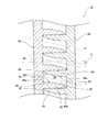
- FIG. 4 is a view for explaining the manufacturing method according to the embodiment of the present invention, and shows a state in which the first mold and the second mold are combined.
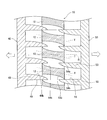
- FIG. 5 is a view for explaining the manufacturing method according to the embodiment of the present invention, and shows a state in which a molten resin is injected into the cavity.
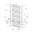
- FIG. 6 is a view for explaining the manufacturing method according to the embodiment of the present invention, and shows a state in which the first mold and the second mold are separated from each other.
- FIG. 7 is a diagram for explaining a manufacturing method according to a comparative example.
- FIG. 8 is a diagram for explaining a manufacturing method according to a modification of the embodiment of the present invention.
- the worm wheel 10 is used in a worm speed reducer 100.
- the worm wheel 10 meshes with the worm shaft 20.
- the worm shaft 20 is connected to a rotating shaft (not shown) of the motor, and the worm wheel 10 is connected to, for example, a pinion (not shown).
- the rotational force output from the motor is transmitted to the rack shaft that rolls the wheel through the worm wheel 10 and the pinion, and assists the driver in steering the wheel.
- the worm wheel 10 When the worm shaft 20 is rotated with the rotation of the rotating shaft of the motor, the worm wheel 10 is rotated. At this time, the rotation of the worm shaft 20 is decelerated and transmitted to the worm wheel 10. As the worm wheel 10 rotates, the pinion rotates. Thus, the worm reduction gear 100 reduces the rotation of the motor via the worm shaft 20 and the worm wheel 10 and transmits it to the pinion.
- the worm shaft 20 has a cylindrical shaft body 21 and shaft teeth 22 formed in a spiral shape on the outer periphery of the shaft body 21.
- the worm wheel 10 includes an annular wheel body 11 and a plurality of wheel teeth 12 protruding from the outer periphery of the wheel body 11.
- the pitch of the wheel teeth 12 is substantially equal to the pitch of the shaft teeth 22, and the wheel teeth 12 mesh with the shaft teeth 22.
- the wheel body 11 and the wheel teeth 12 are made of a resin material and are integrally molded.
- a metal sleeve 17 is provided on the inner periphery of the wheel body 11.
- the wheel teeth 12 are formed on the outer periphery of the worm wheel 10.
- the wheel teeth 12 have first and second tooth surfaces 13 and 14 that intersect with the circumferential direction of the worm wheel 10.
- the second tooth surface 14 is located on the opposite side of the wheel tooth 12 from the first tooth surface 13.
- FIG. 2 is a perspective view showing a part of the worm wheel 10.
- FIG. 3 is a partial development view of the pitch cylindrical surface of the worm wheel 10.
- the wheel teeth 12 have first and second end faces 15 and 16 orthogonal to a direction along the rotation axis R of the worm wheel 10 (hereinafter simply referred to as “rotation axis direction”). Also have.
- the second end face 16 is located on the side opposite to the first end face 15 of the wheel tooth 12.
- the first tooth surface 13 is a curved surface from the first end surface 15 to the flat surface 13 a along the rotation axis R of the worm wheel 10 and from the flat surface portion 13 a to the second end surface 16. And a curved surface portion 13b formed in a shape.
- the curved surface portion 13b is formed by being bent in the D4 direction from the flat surface portion 13a, corresponding to the shaft teeth 22 (see FIG. 1) of the worm shaft 20.
- the second tooth surface 14 has a flat surface portion 14 a and a curved surface portion 14 b, similarly to the first tooth surface 13.
- the flat surface portion 14 a is formed in a planar shape from the second end surface 16 along the rotation axis R of the worm wheel 10.
- the curved surface portion 14 b is formed in a curved surface shape corresponding to the shaft teeth 22 of the worm shaft 20.
- the tooth trace direction of the wheel teeth 12 is inclined with respect to the rotation axis direction.
- tooth trace means an imaginary line passing through the center of the first end face 15 and the center of the second end face 16, and is indicated by a one-dot chain line with a symbol “T” in FIG.
- tooth trace direction means a direction along the tooth trace T.
- the 1st tooth surface 13 has the curved surface part 13b, compared with the case where the whole 1st tooth surface 13 is formed only by the plane part 13a, the 1st tooth surface when the worm shaft 20 rotates to D1 direction
- the contact area between 13 and the shaft teeth 22 can be increased.
- the second tooth surface 14 has the curved surface portion 14b, the second tooth surface 14 is formed when the worm shaft 20 rotates in the direction D2 as compared with the case where the entire second tooth surface 14 is formed by only the flat surface portion 14a.
- the contact area between the two tooth surfaces 14 and the shaft teeth 22 can be increased.
- the contact surface pressure generated on the first and second tooth surfaces 13 and 14 can be reduced by increasing the contact area between the first and second tooth surfaces 13 and 14 and the shaft teeth 22. Therefore, the durability of the wheel teeth 12 can be improved.
- the mold 30 is formed so as to be divided into a first mold block 40 and a second mold block 50.
- the first mold block 40 has a plurality of first molds 43 for molding the first tooth surfaces 13 (see FIG. 3) of the wheel teeth 12.
- the first mold 43 protrudes from the main body 41 of the first mold block 40.
- a flat surface 44 a and a curved surface 44 b are formed on the molding surface 44 of the first mold 43 corresponding to the first tooth surface 13. That is, the flat surface portion 44a is formed in a planar shape along the rotation axis R, and the curved surface portion 44b is formed by being bent in the D4 direction from the flat surface portion 44a.
- the second mold block 50 has a plurality of second molds 53 for molding the second tooth surfaces 14 (see FIG. 3) of the wheel teeth 12.
- the second mold 53 protrudes from the main body 51 of the second mold block 50.
- a flat surface portion 54 a and a curved surface portion 54 b are formed on the molding surface 54 of the second mold 53 corresponding to the second tooth surface 14.
- the molding surface 44 and the molding surface 54 face each other with a space therebetween.
- the tip of the first mold 43 contacts the side surface 52 of the main body 51 of the second mold block 50.
- the distal end of the second mold 53 contacts the side surface 42 of the main body 41 of the first mold block 40.
- the cavity 31 for molding the wheel teeth 12 (see FIG. 3) is defined by the molding surfaces 44 and 54 and the side surfaces 42 and 52. That is, the side surface 42 of the main body 41 forms the first end surface 15 of the wheel tooth 12, and the side surface 52 of the main body 51 forms the second end surface 16 of the wheel tooth 12.
- the surface 45 of the first mold 43 opposite to the molding surface 44 and the molding surface 54 of the second mold 53 are opposite.
- the side surfaces 55 are in contact with each other. That is, the mold 30 can be divided with the surface 45 and the surface 55 as a boundary.
- surface 45 and “surface 55” are also referred to as “divided surface 45” and “divided surface 55”, respectively.
- the first mold block 40 and the second mold block 50 are combined to form the cavity 31.
- molten resin is injected into the cavity 31 to cool the molten resin.
- the resin hardens in a shape corresponding to the shape of the cavity 31, and the resin-made wheel teeth 12 are molded.
- the first mold block 40 and the second mold block 50 are separated from each other in the direction of the rotation axis.
- the molded worm wheel 10 is removed from the first mold block 40 and the second mold block 50.
- the dividing surface 45 of the first mold block 40 and the dividing surface 55 of the second mold block 50 are , Formed along the rotation axis R of the worm wheel 10.
- the curved surface portion 44b of the first mold 43 is formed by being bent in the D4 direction from the flat surface portion 44a along the rotation axis R. Since the dividing surface 45 of the first mold 43 is formed along the rotation axis R, the curved surface portion 44b is formed to be bent so as to approach the dividing surface 45 toward the tip of the first mold 43 from the flat surface portion 44a. The Therefore, the first mold 43 is formed so as to be narrower from the base end (the end of the first mold 43 in the direction of separating the first mold 43) toward the distal end. Therefore, the 1st type
- the curved surface portion 54b of the second mold 53 is formed by being bent in the D3 direction from the flat surface portion 54a along the rotation axis R. Since the dividing surface 55 of the second mold 53 is formed along the rotation axis R, the curved surface portion 54b is bent and formed so as to approach the dividing surface 55 from the flat surface portion 54a toward the tip of the second mold 53. The Therefore, the second mold 53 is formed so as to become narrower from the base end (the end of the second mold 53 in the direction of separating the second mold 53) toward the distal end. Accordingly, the second mold 53 can be extracted from the molded worm wheel 10.
- the first mold block 140 has a plurality of first molds 143 having a molding surface 144 and a split surface 145
- the second mold block 150 has a molding surface 154 and a split surface 155.
- a plurality of second molds 153 are provided.
- the molding surface 144 is formed with a flat surface portion 144a and a curved surface portion 144b
- the molding surface 154 is formed with a flat surface portion 154a and a curved surface portion 154b.
- the first mold block 140 and the second mold block 150 are separated from each other in the tooth trace direction of the wheel teeth 112.
- the dividing surface 145 of the first mold 143 is formed along the tooth trace T. Therefore, the flat surface portion 144a of the first mold 143 is formed along the tooth trace T, and the curved surface portion 144b of the first mold 143 is formed by being bent in the D4 direction from the flat surface portion 144a.
- the flat surface portion 144a when the flat surface portion 144a is formed along the rotation axis R as shown by a two-dotted line in FIG. 7, the flat surface portion 144a is separated from the dividing surface 145 toward the curved surface portion 144b from the base end. So as to extend.
- the curved surface portion 144b is formed by bending from the flat surface portion 144a, a part of the curved surface portion 144b bends away from the dividing surface 145 toward the center of the first mold 143 from the flat surface portion 144a. Therefore, the 1st type
- the flat surface portion 144a is formed along the tooth trace T, the curved surface portion 144b is bent from the flat surface portion 144a. That is, in the comparative example, the flat surface portion 144a cannot be formed so as to be inclined with respect to the tooth trace T, and the curved surface portion 144b is moved toward the center of the first mold 143 from the flat surface portion 144a. Can not be formed to approach.
- the flat portion 113 a of the wheel tooth 112 is formed so as to be inclined with respect to the tooth trace T. I can't. Further, the curved surface portion 113b of the wheel tooth 112 cannot be bent so as to approach the tooth trace T toward the center of the wheel tooth 112 from the flat surface portion 113a. Therefore, the curved surface portion 113b of the wheel tooth 112 cannot be enlarged while being formed in a shape corresponding to the shaft tooth 22 (see FIG. 1) of the worm shaft 20.
- the flat portion 114a of the wheel tooth 112 cannot be formed so as to be inclined with respect to the tooth trace T, and the curved surface portion 114b is closer to the tooth trace T toward the center of the wheel tooth 112 from the flat portion 114a. Can't bend. Therefore, the curved surface portion 114b of the wheel tooth 112 cannot be enlarged while being formed in a shape corresponding to the shaft tooth 22 (see FIG. 1) of the worm shaft 20.
- the first mold block 40 is separated from the second mold block 50 in the direction of the rotation axis, so that the dividing surface 45 of the first mold 43 is formed along the rotation axis R. Is done. Therefore, the flat surface portion 44 a of the first mold 43 formed along the rotation axis R extends along the dividing surface 145. Further, the curved surface portion 44b formed by bending from the flat surface portion 44a is bent so as to approach the dividing surface 45 as it goes from the flat surface portion 44a to the tip of the first mold 43. Therefore, the 1st type
- the flat surface portion 44a can be formed along the rotation axis R, and the curved surface portion 44b can be formed by bending from the flat surface portion 44a. That is, the flat surface portion 44a can be formed so as to be inclined with respect to the tooth trace T, and the curved surface portion 44b is formed so as to approach the tooth trace T toward the center of the first mold 43 from the flat surface portion 44a. can do.
- the flat surface portion 13 a of the wheel tooth 12 is formed to be inclined with respect to the tooth trace T. be able to. Further, the curved surface portion 13b of the wheel tooth 12 can be bent so as to approach the tooth trace T toward the center of the wheel tooth 12 from the flat surface portion 13a. Therefore, the curved surface portion 13b of the wheel tooth 12 can be enlarged while being formed in a shape corresponding to the shaft tooth 22 (see FIG. 1) of the worm shaft 20.
- the dividing surface 55 of the second mold 53 is formed along the rotation axis R. Therefore, the flat surface portion 14a of the wheel tooth 12 can be formed so as to be inclined with respect to the tooth trace T, and the curved surface portion 14b is bent so as to approach the tooth trace T toward the center of the wheel tooth 12 from the flat surface portion 14a. be able to. Therefore, the curved surface portion 14b of the wheel tooth 12 can be enlarged while being formed in a shape corresponding to the shaft tooth 22 (see FIG. 1) of the worm shaft 20.
- the molding surface 44 can be formed to be bent away from the tooth trace T from the center toward the base end until the tangent of the molding surface 44 is parallel to the rotation axis R.
- the molding surface 54 can be bent away from the tooth trace T from the center toward the base end. Therefore, the curved surface portions 13 b and 14 b of the wheel teeth 12 can be made larger while being formed in a shape corresponding to the shaft teeth 22.
- the flat surface portion 13a and the curved surface portion 13b are formed on the first tooth surface 13, but the entire first tooth surface 13 may be formed in a curved surface shape.
- the entire second tooth surface 14 may be formed in a curved surface shape.
- the entire first tooth surface 13 may be formed in a curved shape using the first mold 43
- the entire second tooth surface 14 may be formed in a curved surface using the second mold 53.
- the first and second tooth surfaces When forming the whole of 13 and 14 in the shape of a curved surface, it is not necessary to process the wheel teeth 12 formed by molding. Therefore, the curved surface portions 13b and 14b of the first and second tooth surfaces 13 and 14 can be enlarged with less man-hours.
- the first mold block 40 and the second mold block 50 are not limited to being separated along the rotation axis direction, and may be separated in a direction inclined with respect to the tooth trace T of the wheel tooth 12. Even in this case, the dividing surfaces 45 and 55 of the first mold block 40 and the second mold block 50 are formed to be inclined with respect to the tooth trace T. Therefore, the molding surfaces 44 and 54 of the first mold 43 and the second mold 53 can be formed by bending away from the tooth trace T from the center toward the base end. Therefore, the curved surface portions 13 b and 14 b of the wheel teeth 12 can be enlarged while being formed in a shape corresponding to the shaft teeth 22.
- the direction in which the first mold block 40 and the second mold block 50 are separated is preferably inclined with respect to the tooth trace T toward the rotation axis R.
- the dividing surfaces 45 and 55 are formed so as to be inclined toward the rotation axis R with respect to the tooth trace T. Therefore, the molding surfaces 44 and 54 of the first mold 43 and the second mold 53 can be formed to be bent away from the tooth trace T from the center to the vicinity of the base end. Therefore, the curved surface portions 13 b and 14 b can be enlarged while being formed in a shape corresponding to the shaft teeth 22.
- FIG. 8 is a view for explaining a manufacturing method according to a modification of the present embodiment, and shows a wheel tooth 212 manufactured by this manufacturing method and a mold 230 used in this manufacturing method.
- a cavity 231 for molding the wheel teeth 212 (see FIG. 3) is defined by the first mold block 240 and the second mold block 250.
- the dividing surface 245 of the first mold block 240 is inclined from the tooth trace T toward the rotation axis R and beyond the rotation axis R.
- the dividing surface 255 of the second mold block 250 is inclined from the tooth trace T toward the rotation axis R and beyond the rotation axis R.
- the first mold block 240 and the second mold block 250 are moved along the dividing surfaces 245 and 255, that is, from the tooth trace T to the rotation axis R side and the rotation axis. They are separated from each other in the direction of inclination beyond R.
- the molding surfaces 244 and 254 are formed in curved shapes until the molding surfaces 244 and 254 at the base ends of the first mold 243 and the second mold 253 are parallel to the divided surfaces 245 and 255. it can. Therefore, the curved surface portions 213b and 214b of the first and second tooth surfaces 213 and 214 of the wheel teeth 212 can be enlarged, and the contact area between the wheel teeth 212 and the shaft teeth 22 (see FIG. 1) can be increased. it can.
- the present embodiment relates to a method of manufacturing the worm wheel 10 including a plurality of wheel teeth 12 and 212 that mesh with the shaft teeth 22 of the worm shaft 20.
- the manufacturing method of the worm wheel 10 includes the first molds 43 and 243 for forming the first tooth surfaces 13 and 213 of the wheel teeth 12 and 212 pressed by the shaft teeth 22 when the worm shaft 20 rotates in the D1 direction, and the D2 direction.
- the second molds 53 and 253 for forming the second tooth surfaces 14 and 214 of the wheel teeth 12 and 212 that are pushed by the shaft teeth 22 when the worm shaft 20 rotates to the first molds 43 and 243 and the first molds 43 and 243 are combined.
- the dividing surface of the first molds 43 and 243 and the second molds 53 and 253 is separated. 45, 245, 55, and 255 are formed to be inclined with respect to the tooth trace T. Therefore, the molding surfaces 44, 244, 54, 254 of the first molds 43, 243 and the second molds 53, 253 can be formed to be bent away from the tooth trace T from the center toward the base end. Therefore, the curved surface portions 13b, 213b, 14b, and 214b of the wheel teeth 12 and 212 can be enlarged while being formed in a shape corresponding to the shaft teeth 22.
- the first molds 43 and 243 and the second molds 53 and 253 are separated from each other in a direction inclined toward the rotation axis R with respect to the tooth trace T of the wheel teeth 12 and 212.
- the first molds 43 and 243 and the second molds 53 and 253 are separated from each other in a direction inclined toward the rotation axis R with respect to the tooth traces T of the wheel teeth 12 and 212.
- the second molds 53 and 253 are formed so that the dividing surfaces 45, 245, 55 and 255 are inclined with respect to the tooth trace T toward the rotation axis R. Therefore, the molding surfaces 44, 244, 54, 254 of the first molds 43, 243 and the second molds 53, 253 can be formed to be bent away from the tooth trace T from the center to the vicinity of the proximal end. Therefore, the curved surface portions 13b, 213b, 14b, and 214b of the wheel teeth 12 and 212 can be enlarged while being formed in a shape corresponding to the shaft teeth 22.
- the first mold 43 and the second mold 53 are separated from each other in the direction along the rotation axis R of the worm wheel 10.
- the molding surfaces 44 and 54 can be formed to be bent away from the tooth trace T from the center toward the base end until the tangent lines of the molding surfaces 44 and 54 are parallel to the rotation axis R. Therefore, the curved surface portions 13 b and 14 b of the wheel teeth 12 can be made larger while being formed in a shape corresponding to the shaft teeth 22.
- the worm wheel 10 is manufactured by forming the entire first tooth surfaces 13 and 213 into a curved surface using the first molds 43 and 243 and using the second molds 53 and 253 to form the second tooth surfaces 14 and 14.
- the entirety of 214 is formed into a curved surface.
- the entire first tooth surfaces 13 and 213 are formed into a curved surface shape using the first molds 43 and 243, and the entire second tooth surfaces 14 and 214 are formed into a curved surface shape using the second molds 53 and 253. Therefore, when the entire first and second tooth surfaces 13, 213, 14, and 214 are formed into a curved surface, it is not necessary to add processing to the wheel teeth 12 and 212 formed by molding. Therefore, the curved surface portions 13b, 213b, 14b, and 214b of the wheel teeth 12 and 212 can be enlarged with less man-hours.
- the wheel teeth 12, 212 are made of resin.
- the wheel teeth 12, 212 may be formed from a meltable material.
Landscapes
- Engineering & Computer Science (AREA)
- General Engineering & Computer Science (AREA)
- Mechanical Engineering (AREA)
- Manufacturing & Machinery (AREA)
- Physics & Mathematics (AREA)
- Electromagnetism (AREA)
- Thermal Sciences (AREA)
- Transportation (AREA)
- Combustion & Propulsion (AREA)
- Chemical & Material Sciences (AREA)
- Gears, Cams (AREA)
- Moulds For Moulding Plastics Or The Like (AREA)
- Power Steering Mechanism (AREA)
- Gear Transmission (AREA)
Abstract
ウォームホイール10の製造方法は、D1方向へのウォームシャフト20の回転時にシャフト歯22によって押されるホイール歯12の第1歯面13を成形する第1型43と、D2方向へのウォームシャフト20の回転時にシャフト歯22によって押されるホイール歯12の第2歯面14を成形する第2型53と、を組み合わせて、第1型43と第2型53とによって画定されるキャビティ31を形成する工程と、キャビティ31に溶融樹脂を注入し、ホイール歯12を成形する工程と、第1型43及び第2型53を、ホイール歯12の歯筋Tに対して傾斜する方向に互いに引き離す工程と、を備える。
Description
本発明は、ウォームホイールの製造方法に関する。
ウォームシャフト及びウォームホイールを介して、電動モータの回転力をラック軸に伝達する電動パワーステアリング装置が知られている。ウォームホイールは、ウォームシャフトの歯と噛み合う複数の歯を有する。ウォームホイールの各歯は、ウォームシャフトが所定の方向に回転するときにウォームシャフトの歯によって押される第1歯面と、ウォームシャフトが逆方向に回転するときにウォームシャフトの歯によって押される第2歯面とを有する。
JP2013-160334Aには、第1歯面の一部及び第2歯面の一部が凹曲面状に形成されたウォームホイールが開示されている。具体的には、歯面の略半分の領域が凹曲面部分として形成され、他方の領域がヘリカル面部分として形成される。凹曲面部分は、歯の中央から端に向かうほど歯筋から離れるように形成され、ヘリカル面部分は、歯筋と平行に形成される。
また、JP2013-160334Aには、第1型と第2型とに分割可能な成形型を用いてウォームホイールを製造する方法が開示されている。第1型は第1歯面を成形する第1成形面を有し、第2型は第2歯面を成形する第2成形面を有する。第1型と第2型とは、第1成形面と第2成形面とが間隔を空けて対向しかつ第1型における第1成形面とは反対側の第1分割面が第2型における第2成形面とは反対側の第2分割面と接触するように、互いに組み合わされる。ウォームホイールの歯を成形するためのキャビティは、第1成形面と第2成形面とによって画定される。成形後のウォームホイールは、第1型と第2型を歯筋方向に沿って互いに引き離すことによって、第1型と第2型から取り外される。
ウォームホイールがウォームシャフトと噛み合うと、ウォームホイールの歯に接触面圧が生じる。この接触面圧は、第1歯面及び第2歯面の曲面部を、ウォームシャフトの歯に対応した形状で形成しウォームシャフトとウォームホイールの歯どうしの接触面積を大きくすることによって低減される。接触面圧をより低減するために、曲面部をさらに大きくすることが望まれている。
しかしながら、JP2013-160334Aに開示される方法では、第1型及び第2型から成形後のウォームホイールを取り外す際に、第1型及び第2型が歯筋方向に互いに引き離される。第1型及び第2型を歯筋方向に互いに引き離すためには、第1分割面及び第2分割面を歯筋方向に平行に形成する必要がある。そのため、第1歯面及び第2歯面の曲面部を大きくすることができない。
仮に、第1歯面及び第2歯面の曲面部を大きくすると、第1型の第1成形面及び第2型の第2成形面は、歯の中央から一端に向かうほど歯筋から離れるように形成されるだけでなく、歯の中央から他端に向かうほど歯筋から離れるように形成される。第1分割面及び第2分割面が歯筋に沿って形成されるので、第1型及び第2型の中央部が両端部よりも太くなる。そのため、第1型及び第2型を成形後のウォームホイールから抜き出すことができない。
このように、JP2013-160334Aに開示される方法では、第1歯面及び第2歯面の曲面部を大きくすることができない。
本発明は、ウォームホイールの歯面の曲面部をウォームシャフトの歯に対応した形状で形成しつつ大きくすることを目的とする。
本発明は、ウォームシャフトのシャフト歯と噛み合う複数のホイール歯を備えるウォームホイールを製造する方法に関する。本発明のある態様によれば、ウォームホイールの製造方法は、所定の方向へのウォームシャフトの回転時にシャフト歯によって押されるホイール歯の第1歯面を成形する第1型と、逆方向へのウォームシャフトの回転時にシャフト歯によって押されるホイール歯の第2歯面を成形する第2型と、を組み合わせて、第1型と第2型とによって画定されるキャビティを形成する工程と、キャビティに溶融材料を注入し、ホイール歯を成形する工程と、第1型及び第2型を、ホイール歯の歯筋に対して傾斜する方向に互いに引き離す工程と、を備える。
以下、図面を参照して、本発明の実施形態に係るウォームホイール10の製造方法について説明する。
図1に示すように、ウォームホイール10は、ウォーム減速機100に用いられる。ウォーム減速機100では、ウォームホイール10はウォームシャフト20と噛み合う。ウォームシャフト20はモータの回転軸(不図示)に連結され、ウォームホイール10は例えばピニオン(不図示)に連結される。モータから出力される回転力は、ウォームホイール10及びピニオンを通じて車輪を転蛇するラック軸に伝達され、ドライバーによる車輪の操舵を補助する。
モータの回転軸の回転に伴ってウォームシャフト20が回転すると、ウォームホイール10が回転する。このとき、ウォームシャフト20の回転は、減速してウォームホイール10に伝達される。ウォームホイール10の回転に伴って、ピニオンが回転する。このように、ウォーム減速機100は、モータの回転をウォームシャフト20及びウォームホイール10を介して減速してピニオンに伝達する。
ウォームシャフト20は、円柱状のシャフト本体21と、シャフト本体21の外周に螺旋状に形成されるシャフト歯22と、を有する。ウォームホイール10は、円環状のホイール本体11と、ホイール本体11の外周から突出する複数のホイール歯12と、を有する。ホイール歯12のピッチは、シャフト歯22のピッチとほぼ等しく、ホイール歯12がシャフト歯22と噛み合う。
ホイール本体11及びホイール歯12は、樹脂材料からなり一体的に成形される。ホイール本体11の内周には金属製のスリーブ17が設けられる。
ホイール歯12は、ウォームホイール10の外周に形成される。また、ホイール歯12は、ウォームホイール10の周方向と交差する第1及び第2歯面13,14を有する。第2歯面14は、ホイール歯12の第1歯面13とは反対側に位置する。
ウォームシャフト20が所定の方向(図1に示すD1方向)に回転すると、ホイール歯12の第1歯面13がシャフト歯22によって押される。その結果、ウォームホイール10は、図1に示すD3方向に回転する。ウォームシャフト20が逆方向(図1に示すD2方向)に回転すると、ホイール歯12の第2歯面14がシャフト歯22によって押される。その結果、ウォームホイール10は、図1に示すD4方向に回転する。
図2は、ウォームホイール10の一部を示す斜視図である。図3は、ウォームホイール10のピッチ円筒面の部分展開図である。
図2及び図3に示すように、ホイール歯12は、ウォームホイール10の回転軸Rに沿う方向(以下、単に「回転軸方向」と称する)と直交する第1及び第2端面15,16を更に有する。第2端面16は、ホイール歯12の第1端面15とは反対側に位置する。
図3に示すように、第1歯面13は、ウォームホイール10の回転軸Rに沿って第1端面15から平面状に形成される平面部13aと、平面部13aから第2端面16まで曲面状に形成される曲面部13bと、を有する。曲面部13bは、ウォームシャフト20のシャフト歯22(図1参照)に対応して、平面部13aからD4方向に曲げられて形成される。
第2歯面14は、第1歯面13と同様に、平面部14aと曲面部14bとを有する。平面部14aは、ウォームホイール10の回転軸Rに沿って第2端面16から平面状に形成される。曲面部14bは、ウォームシャフト20のシャフト歯22に対応した形状で曲面状に形成される。
第1歯面13に曲面部13bが形成され第2歯面14に曲面部14bが形成されるので、ホイール歯12の歯筋方向は、回転軸方向に対して傾斜する。
ここで、「歯筋」は、第1端面15の中心と第2端面16の中心とを通る仮想線を意味し、図3において符合「T」が付された一点鎖線で示される。「歯筋方向」は、歯筋Tに沿った方向を意味する。
第1歯面13が曲面部13bを有するので、第1歯面13の全体が平面部13aのみによって形成された場合と比較して、ウォームシャフト20がD1方向に回転するときの第1歯面13とシャフト歯22との接触面積を増やすことができる。同様に、第2歯面14が曲面部14bを有するので、第2歯面14の全体が平面部14aのみによって形成された場合と比較して、ウォームシャフト20がD2方向に回転するときの第2歯面14とシャフト歯22との接触面積を増やすことができる。
第1及び第2歯面13,14とシャフト歯22との接触面積が増加することによって、第1及び第2歯面13,14に生じる接触面圧を低減することができる。したがって、ホイール歯12の耐久性を向上させることができる。
次に、ウォームホイール10のホイール歯12を成形するための金型30について、図4から図6を参照して説明する。金型30は、第1金型ブロック40と第2金型ブロック50とに分割可能に形成される。
第1金型ブロック40は、ホイール歯12の第1歯面13(図3参照)を成形する複数の第1型43を有する。第1型43は、第1金型ブロック40の本体部41から突出する。第1型43の成形面44には、第1歯面13に対応して、平面部44aと曲面部44bとが形成される。つまり、平面部44aは回転軸Rに沿って平面状に形成され、曲面部44bは平面部44aからD4方向に曲げられて形成される。
第2金型ブロック50は、ホイール歯12の第2歯面14(図3参照)を成形する複数の第2型53を有する。第2型53は、第2金型ブロック50の本体部51から突出する。第2型53の成形面54には、第2歯面14に対応して、平面部54aと曲面部54bとが形成される。
第1金型ブロック40と第2金型ブロック50とを組み合わせた状態では、成形面44と成形面54とが間隔を空けて対向する。第1型43の先端は、第2金型ブロック50の本体部51の側面52に接触する。第2型53の先端は、第1金型ブロック40の本体部41の側面42に接触する。
ホイール歯12(図3参照)を成形するためのキャビティ31は、成形面44,54、及び側面42、52によって画定される。つまり、本体部41の側面42がホイール歯12の第1端面15を成形し、本体部51の側面52がホイール歯12の第2端面16を成形する。
また、第1金型ブロック40と第2金型ブロック50とを組み合わせた状態では、第1型43における成形面44とは反対側の面45と、第2型53における成形面54とは反対側の面55と、が互いに接する。つまり、金型30は、面45及び面55を境に分割可能である。以下において、「面45」、「面55」を、それぞれ、「分割面45」、「分割面55」とも称する。
次に、ウォームホイール10の製造方法、より具体的にはホイール歯12の成形方法について説明する。
まず、図4に示すように、第1金型ブロック40と第2金型ブロック50とを組み合わせ、キャビティ31を形成する。次に、図5に示すように、キャビティ31に溶融樹脂を注入し、溶融樹脂を冷却する。樹脂がキャビティ31の形状に対応した形状で固まり、樹脂製のホイール歯12が成形される。
次に、図6に示すように、第1金型ブロック40と第2金型ブロック50とを回転軸方向に互いに引き離す。その結果、成形後のウォームホイール10が第1金型ブロック40と第2金型ブロック50とから取り外される。
本実施形態では、第1金型ブロック40及び第2金型ブロック50が回転軸方向に互いに引き離されるので、第1金型ブロック40の分割面45及び第2金型ブロック50の分割面55は、ウォームホイール10の回転軸Rに沿って形成される。
第1型43の曲面部44bは、前述のように、回転軸Rに沿う平面部44aからD4方向に曲げられて形成される。第1型43の分割面45が回転軸Rに沿って形成されるので、曲面部44bは、平面部44aから第1型43の先端に向かうほど分割面45に近づくように曲げられて形成される。そのため、第1型43は、基端(第1型43を引き離す方向における第1型43の端部)から先端に向かうほど細く形成される。したがって、第1型43を成形後のウォームホイール10から抜き出すことができる。
同様に、第2型53の曲面部54bは、回転軸Rに沿う平面部54aからD3方向に曲げられて形成される。第2型53の分割面55が回転軸Rに沿って形成されるので、曲面部54bは、平面部54aから第2型53の先端に向かうほど分割面55に近づくように曲げられて形成される。そのため、第2型53は、基端(第2型53を引き離す方向における第2型53の端部)から先端に向かうほど細く形成される。したがって、第2型53を成形後のウォームホイール10から抜き出すことができる。
ここで、比較例に係るウォームホイールの製造方法について、図7を参照して説明する。比較例においても、第1金型ブロック140は、成形面144と分割面145とを有する複数の第1型143を有し、第2金型ブロック150は、成形面154と分割面155とを有する複数の第2型153を有する。成形面144には平面部144aと曲面部144bとが形成され、成形面154には平面部154aと曲面部154bとが形成されている。
比較例では、第1金型ブロック140と第2金型ブロック150とは、ホイール歯112の歯筋方向に互いに引き離される。この場合、第1型143の分割面145は、歯筋Tに沿って形成される。そのため、第1型143の平面部144aは歯筋Tに沿って形成され、第1型143の曲面部144bは平面部144aからD4方向に曲げられて形成される。
仮に、比較例において、図7に2点差線で示すように、平面部144aを回転軸Rに沿って形成した場合、平面部144aは、基端から曲面部144bに向かうほど分割面145から離れるように延在する。また、曲面部144bを平面部144aから曲げて形成した場合、曲面部144bの一部は、平面部144aから第1型143の中央に向かうほど分割面145から離れるように曲がる。そのため、第1型143は、基端から中央に向かうほど太く形成される。したがって、第1型143を成形後のウォームホイールから抜き出すことができない。
このように、比較例では、平面部144aを歯筋Tに沿って形成しているため曲面部144bを平面部144aから曲げて形成する。つまり、比較例では、平面部144aを歯筋Tに対して傾斜するように形成することができず、また、曲面部144bを、平面部144aから第1型143の中央に向かうほど歯筋Tに近づくように形成することができない。
ホイール歯112の第1歯面113は第1型143の成形面144の形状に対応した形状で成形されるので、ホイール歯112の平面部113aを歯筋Tに対して傾斜するように形成することができない。また、ホイール歯112の曲面部113bを平面部113aからホイール歯112の中央へ向かうほど歯筋Tに近づくように曲げることができない。したがって、ホイール歯112の曲面部113bを、ウォームシャフト20のシャフト歯22(図1参照)に対応した形状で形成しつつ大きくすることができない。
同様に、比較例では、第2型153の分割面155を歯筋Tに沿って形成する必要がある。そのため、ホイール歯112の平面部114aを歯筋Tに対して傾斜するように形成することができず、曲面部114bを平面部114aからホイール歯112の中央へ向かうほど歯筋Tに近づくように曲げることができない。したがって、ホイール歯112の曲面部114bを、ウォームシャフト20のシャフト歯22(図1参照)に対応した形状で形成しつつ大きくすることができない。
本実施形態では、図6に示すように、第1金型ブロック40が第2金型ブロック50から回転軸方向に引き離されるので、第1型43の分割面45が回転軸Rに沿って形成される。そのため、回転軸Rに沿って形成された第1型43の平面部44aは、分割面145に沿って延在する。また、平面部44aから曲げて形成された曲面部44bは、平面部44aから第1型43の先端に向かうほど分割面45に近づくように曲がる。そのため、第1型43は、基端から先端に向かうほど細く形成される。したがって、第1型43を成形後のウォームホイール10から抜き出すことができる。
このように、本実施形態では、平面部44aを回転軸Rに沿って形成することができ曲面部44bを平面部44aから曲げて形成することができる。つまり、平面部44aを歯筋Tに対して傾斜するように形成することができ、また、曲面部44bを、平面部44aから第1型43の中央に向かうほど歯筋Tに近づくように形成することができる。
ホイール歯12の第1歯面13は第1型43の成形面44の形状に対応した形状で成形されるので、ホイール歯12の平面部13aを歯筋Tに対して傾斜するように形成することができる。また、ホイール歯12の曲面部13bを平面部13aからホイール歯12の中央へ向かうほど歯筋Tに近づくように曲げることができる。したがって、ホイール歯12の曲面部13bを、ウォームシャフト20のシャフト歯22(図1参照)に対応した形状で形成しつつ大きくすることができる。
同様に、第2型53の分割面55は回転軸Rに沿って形成される。そのため、ホイール歯12の平面部14aを歯筋Tに対して傾斜するように形成することができ、曲面部14bを平面部14aからホイール歯12の中央へ向かうほど歯筋Tに近づくように曲げることができる。したがって、ホイール歯12の曲面部14bを、ウォームシャフト20のシャフト歯22(図1参照)に対応した形状で形成しつつ大きくすることができる。
また、本実施形態では、第1型43が第2型53から回転軸方向に引き離されるので、第1型43の分割面45が回転軸Rに沿って形成される。そのため、成形面44の接線が回転軸Rと平行になるまで、成形面44を、中央から基端に向かうほど歯筋Tから離れるように曲げて形成することができる。同様に、成形面54の接線が回転軸Rと平行になるまで、成形面54を、中央から基端に向かうほど歯筋Tから離れるように曲げて形成することができる。したがって、ホイール歯12の曲面部13b,14bをシャフト歯22に対応した形状で形成しつつより大きくすることができる。
本実施形態では、第1歯面13に平面部13aと曲面部13bが形成されるが、第1歯面13の全体が曲面状に形成されていてもよい。同様に、第2歯面14の全体が曲面状に形成されていてもよい。つまり、第1型43を用いて第1歯面13の全体を曲面状に形成し、第2型53を用いて第2歯面14の全体を曲面状に形成してもよい。
第1型43を用いて第1歯面13の全体が曲面状に形成され第2型53を用いて第2歯面14の全体が曲面状に形成されるので、第1及び第2歯面13,14の全体を曲面状に形成する際に、型成形によって成形したホイール歯12に加工を加える必要がない。したがって、より少ない工数で第1及び第2歯面13,14の曲面部13b,14bを大きくすることができる。
第1金型ブロック40及び第2金型ブロック50は、回転軸方向に沿って引き離される形態に限られず、ホイール歯12の歯筋Tに対して傾斜する方向に引き離されればよい。この場合であっても、第1金型ブロック40と第2金型ブロック50との分割面45,55は、歯筋Tに対して傾斜して形成される。そのため、第1型43及び第2型53の成形面44,54を、中央から基端に向かうほど歯筋Tから離れるように曲げて形成することができる。したがって、ホイール歯12の曲面部13b,14bをシャフト歯22に対応した形状で形成しつつ大きくすることができる。
第1金型ブロック40及び第2金型ブロック50を引き離す方向は、歯筋Tに対して回転軸R側に傾斜していることが好ましい。この場合には、分割面45,55は、歯筋Tに対して回転軸R側に傾斜して形成される。そのため、第1型43及び第2型53の成形面44,54を、中央から基端の近傍まで歯筋Tから離れるように曲げて形成することができる。したがって、曲面部13b,14bをシャフト歯22に対応した形状で形成しつつ大きくすることができる。
図8は、本実施形態の変形例に係る製造方法を説明するための図であり、この製造方法によって製造されるホイール歯212、及びこの製造方法において用いられる金型230を示す。ホイール歯212(図3参照)を成形するためのキャビティ231は、第1金型ブロック240と第2金型ブロック250とによって画定される。
第1金型ブロック240の分割面245は、歯筋Tから回転軸R側にかつ回転軸Rを超えて傾斜している。同様に、第2金型ブロック250の分割面255は、歯筋Tから回転軸R側にかつ回転軸Rを超えて傾斜している。金型230では、ホイール歯212の成形後に、第1金型ブロック240と第2金型ブロック250とが、分割面245,255に沿って、つまり歯筋Tから回転軸R側にかつ回転軸Rを超えて傾斜する方向に互いに引き離される。
変形例に係る製造方法では、第1型243及び第2型253の基端における成形面244,254が分割面245,255と平行になるまで成形面244,254を曲面状に形成することができる。したがって、ホイール歯212の第1及び第2歯面213,214の曲面部213b,214bを拡大させることができ、ホイール歯212とシャフト歯22(図1参照)との接触面積を大きくすることができる。
以下、本発明の実施形態の構成、作用、及び効果をまとめて説明する。
本実施形態は、ウォームシャフト20のシャフト歯22と噛み合う複数のホイール歯12,212を備えるウォームホイール10の製造方法に係る。ウォームホイール10の製造方法は、D1方向へのウォームシャフト20の回転時にシャフト歯22によって押されるホイール歯12,212の第1歯面13,213を成形する第1型43,243と、D2方向へのウォームシャフト20の回転時にシャフト歯22によって押されるホイール歯12,212の第2歯面14,214を成形する第2型53,253と、を組み合わせて、第1型43,243と第2型53,253とによって画定されるキャビティ31,231を形成する工程と、キャビティ31,231に溶融樹脂を注入し、ホイール歯12,212を成形する工程と、第1型43,243及び第2型53,253を、ホイール歯12,212の歯筋Tに対して傾斜する方向に互いに引き離す工程と、を備える。
この構成では、第1型43,243及び第2型53,253が歯筋Tに対して傾斜する方向に互いに引き離されるので、第1型43,243と第2型53,253との分割面45,245,55,255は、歯筋Tに対して傾斜して形成される。そのため、第1型43,243及び第2型53,253の成形面44,244,54,254を、中央から基端に向かうほど歯筋Tから離れるように曲げて形成することができる。したがって、ホイール歯12,212の曲面部13b,213b,14b,214bをシャフト歯22に対応した形状で形成しつつ大きくすることができる。
また、ウォームホイール10の製造方法は、ホイール歯12,212の歯筋Tに対して回転軸R側に傾斜する方向に第1型43,243及び第2型53,253を互いに引き離す。
この構成では、第1型43,243及び第2型53,253がホイール歯12,212の歯筋Tに対して回転軸R側に傾斜する方向に互いに引き離されるので、第1型43,243と第2型53,253との分割面45,245,55,255は、歯筋Tに対して回転軸R側に傾斜して形成される。そのため、第1型43,243及び第2型53,253の成形面44,244,54,254を、中央から基端の近傍まで歯筋Tから離れるように曲げて形成することができる。したがって、ホイール歯12,212の曲面部13b,213b,14b,214bをシャフト歯22に対応した形状で形成しつつ大きくすることができる。
また、ウォームホイール10の製造方法は、ウォームホイール10の回転軸Rに沿う方向に第1型43及び第2型53を互いに引き離す。
この構成では、第1型43及び第2型53が回転軸方向に互いに引き離されるので、第1型43と第2型53との分割面45,55は、回転軸Rに沿って形成される。そのため、成形面44,54の接線が回転軸Rと平行になるまで、成形面44,54を、中央から基端に向かうほど歯筋Tから離れるように曲げて形成することができる。したがって、ホイール歯12の曲面部13b,14bをシャフト歯22に対応した形状で形成しつつより大きくすることができる。
また、ウォームホイール10の製造方法は、第1型43,243を用いて第1歯面13,213の全体を曲面状に形成するとともに第2型53,253を用いて第2歯面14,214の全体を曲面状に形成する。
この構成では、第1型43,243を用いて第1歯面13,213の全体が曲面状に形成され第2型53,253を用いて第2歯面14,214の全体が曲面状に形成されるので、第1及び第2歯面13,213,14,214の全体を曲面状に形成する際に、型成形によって成形したホイール歯12,212に加工を加える必要がない。したがって、より少ない工数でホイール歯12,212の曲面部13b,213b,14b,214bを大きくすることができる。
以上、本発明の実施形態について説明したが、上記実施形態は本発明の適用例の一部を示したに過ぎず、本発明の技術的範囲を上記実施形態の具体的構成に限定する趣旨ではない。
例えば、上記実施形態では、ホイール歯12,212は樹脂からなる。樹脂に代え、溶融可能な材料からホイール歯12,212が形成されていてもよい。
本願は2016年3月28日に日本国特許庁に出願された特願2016-63851に基づく優先権を主張し、この出願の全ての内容は参照により本明細書に組み込まれる。
Claims (4)
- ウォームシャフトのシャフト歯と噛み合う複数のホイール歯を備えるウォームホイールの製造方法であって、
所定の方向への前記ウォームシャフトの回転時に前記シャフト歯によって押される前記ホイール歯の第1歯面を成形する第1型と、逆方向への前記ウォームシャフトの回転時に前記シャフト歯によって押される前記ホイール歯の第2歯面を成形する第2型と、を組み合わせて、前記第1型と前記第2型とによって画定されるキャビティを形成する工程と、
前記キャビティに溶融材料を注入し、前記ホイール歯を成形する工程と、
前記第1型及び前記第2型を、前記ホイール歯の歯筋に対して傾斜する方向に互いに引き離す工程と、を備える
ウォームホイールの製造方法。 - 請求項1に記載のウォームホイールの製造方法であって、
前記ホイール歯の歯筋に対して前記ウォームホイールの回転軸側に傾斜する方向に前記第1型及び前記第2型を互いに引き離す
ウォームホイールの製造方法。 - 請求項1に記載のウォームホイールの製造方法であって、
前記ウォームホイールの回転軸に沿う方向に前記第1型及び前記第2型を互いに引き離す
ウォームホイールの製造方法。 - 請求項1に記載のウォームホイールの製造方法であって、
前記第1型を用いて前記第1歯面の全体を曲面状に形成するとともに前記第2型を用いて前記第2歯面の全体を曲面状に形成する
ウォームホイールの製造方法。
Priority Applications (3)
| Application Number | Priority Date | Filing Date | Title |
|---|---|---|---|
| US16/087,096 US20210178712A1 (en) | 2016-03-28 | 2017-02-16 | Method for manufacturing worm wheel |
| CN201780021126.9A CN108884925A (zh) | 2016-03-28 | 2017-02-16 | 蜗轮的制造方法 |
| DE112017001589.8T DE112017001589T5 (de) | 2016-03-28 | 2017-02-16 | Verfahren zur Herstellung eines Schneckenrades |
Applications Claiming Priority (2)
| Application Number | Priority Date | Filing Date | Title |
|---|---|---|---|
| JP2016-063851 | 2016-03-28 | ||
| JP2016063851A JP6180574B1 (ja) | 2016-03-28 | 2016-03-28 | ウォームホイールの製造方法 |
Publications (1)
| Publication Number | Publication Date |
|---|---|
| WO2017169250A1 true WO2017169250A1 (ja) | 2017-10-05 |
Family
ID=59604866
Family Applications (1)
| Application Number | Title | Priority Date | Filing Date |
|---|---|---|---|
| PCT/JP2017/005739 Ceased WO2017169250A1 (ja) | 2016-03-28 | 2017-02-16 | ウォームホイールの製造方法 |
Country Status (5)
| Country | Link |
|---|---|
| US (1) | US20210178712A1 (ja) |
| JP (1) | JP6180574B1 (ja) |
| CN (1) | CN108884925A (ja) |
| DE (1) | DE112017001589T5 (ja) |
| WO (1) | WO2017169250A1 (ja) |
Citations (4)
| Publication number | Priority date | Publication date | Assignee | Title |
|---|---|---|---|---|
| JPH0263661A (ja) * | 1988-08-31 | 1990-03-02 | Honda Motor Co Ltd | 羽根車の鋳造方法および鋳造装置 |
| JP2007245521A (ja) * | 2006-03-15 | 2007-09-27 | Shangyin Sci & Technol Co Ltd | ボール連結チェーンの製造方法 |
| JP2009137067A (ja) * | 2007-12-04 | 2009-06-25 | Aisin Seiki Co Ltd | ウォームホイールギヤ成形用の金型製造方法及びウォームホイールギヤ成形用の金型 |
| JP2013160334A (ja) * | 2012-02-07 | 2013-08-19 | Jtekt Corp | ウォームホイール |
Family Cites Families (1)
| Publication number | Priority date | Publication date | Assignee | Title |
|---|---|---|---|---|
| JP5719963B1 (ja) | 2014-09-08 | 2015-05-20 | 株式会社美創 | 身飾品製造方法、身飾品成形用金型及び身飾品 |
-
2016
- 2016-03-28 JP JP2016063851A patent/JP6180574B1/ja active Active
-
2017
- 2017-02-16 DE DE112017001589.8T patent/DE112017001589T5/de not_active Withdrawn
- 2017-02-16 US US16/087,096 patent/US20210178712A1/en not_active Abandoned
- 2017-02-16 WO PCT/JP2017/005739 patent/WO2017169250A1/ja not_active Ceased
- 2017-02-16 CN CN201780021126.9A patent/CN108884925A/zh active Pending
Patent Citations (4)
| Publication number | Priority date | Publication date | Assignee | Title |
|---|---|---|---|---|
| JPH0263661A (ja) * | 1988-08-31 | 1990-03-02 | Honda Motor Co Ltd | 羽根車の鋳造方法および鋳造装置 |
| JP2007245521A (ja) * | 2006-03-15 | 2007-09-27 | Shangyin Sci & Technol Co Ltd | ボール連結チェーンの製造方法 |
| JP2009137067A (ja) * | 2007-12-04 | 2009-06-25 | Aisin Seiki Co Ltd | ウォームホイールギヤ成形用の金型製造方法及びウォームホイールギヤ成形用の金型 |
| JP2013160334A (ja) * | 2012-02-07 | 2013-08-19 | Jtekt Corp | ウォームホイール |
Also Published As
| Publication number | Publication date |
|---|---|
| US20210178712A1 (en) | 2021-06-17 |
| JP2017180512A (ja) | 2017-10-05 |
| JP6180574B1 (ja) | 2017-08-16 |
| CN108884925A (zh) | 2018-11-23 |
| DE112017001589T5 (de) | 2018-12-13 |
Similar Documents
| Publication | Publication Date | Title |
|---|---|---|
| CN101939570B (zh) | 蜗轮、蜗轮用注射成型模具的制造方法及蜗轮的制造方法 | |
| KR20100138761A (ko) | 파동기어장치 | |
| CN106573291B (zh) | 齿条以及齿条的制造方法 | |
| JP5141329B2 (ja) | ウォームギヤ | |
| JP5873724B2 (ja) | 歯車装置 | |
| JP6180574B1 (ja) | ウォームホイールの製造方法 | |
| JP5857770B2 (ja) | ウォームホイールの製造方法及びウォームホイールの製造装置 | |
| JP7323164B2 (ja) | 可撓性外歯歯車および波動歯車装置 | |
| JP7099253B2 (ja) | 歯車の鍛造成形方法及び鍛造成形装置 | |
| JP2004148525A (ja) | 筒状部材および筒状部材装置および筒状部材を成形するための金型 | |
| JP2007098632A (ja) | 歯車の製造方法、歯車の製造装置、歯車、並びに減速機構付きモータ | |
| JP2004223813A (ja) | ウォームホイールの製造用成形型 | |
| JP4203714B2 (ja) | ウォームホイールの製造方法 | |
| JP4273296B2 (ja) | ウォームホイールとその製造用成形型 | |
| JP2007181955A (ja) | 射出成形用金型装置 | |
| JP6393599B2 (ja) | ヘリカルギヤ及びその製造方法 | |
| JP5607803B1 (ja) | 台形歯すじ歯車 | |
| WO2024209642A1 (ja) | 可撓性外歯歯車の成形型および成形方法 | |
| JP3158242B2 (ja) | 内周に凹凸部を有する部品の製造方法 | |
| JP2004098070A (ja) | ヘリカルギア、その製造装置及び製造方法 | |
| CN121773280A (zh) | 蜗轮以及蜗轮的制造方法 | |
| JP2008055649A (ja) | ウォームホイール成形用型および成形方法 | |
| JP2009137067A (ja) | ウォームホイールギヤ成形用の金型製造方法及びウォームホイールギヤ成形用の金型 | |
| JP2016205265A (ja) | トルク伝達装置及びその製造方法 | |
| JP2019047597A (ja) | ギアードモータ |
Legal Events
| Date | Code | Title | Description |
|---|---|---|---|
| 121 | Ep: the epo has been informed by wipo that ep was designated in this application |
Ref document number: 17773798 Country of ref document: EP Kind code of ref document: A1 |
|
| 122 | Ep: pct application non-entry in european phase |
Ref document number: 17773798 Country of ref document: EP Kind code of ref document: A1 |