WO2017168474A1 - Cellule de batterie solaire, module solaire, et procédé de fabrication de cellule de batterie solaire - Google Patents
Cellule de batterie solaire, module solaire, et procédé de fabrication de cellule de batterie solaire Download PDFInfo
- Publication number
- WO2017168474A1 WO2017168474A1 PCT/JP2016/004425 JP2016004425W WO2017168474A1 WO 2017168474 A1 WO2017168474 A1 WO 2017168474A1 JP 2016004425 W JP2016004425 W JP 2016004425W WO 2017168474 A1 WO2017168474 A1 WO 2017168474A1
- Authority
- WO
- WIPO (PCT)
- Prior art keywords
- conversion layer
- photoelectric conversion
- height
- disposed
- wiring member
- Prior art date
Links
- 238000004519 manufacturing process Methods 0.000 title claims description 11
- 238000000034 method Methods 0.000 title claims description 11
- 238000006243 chemical reaction Methods 0.000 claims abstract description 116
- 239000000463 material Substances 0.000 claims abstract description 66
- 238000007650 screen-printing Methods 0.000 claims description 15
- 239000000853 adhesive Substances 0.000 description 33
- 230000001070 adhesive effect Effects 0.000 description 33
- 239000010408 film Substances 0.000 description 25
- 238000007789 sealing Methods 0.000 description 23
- 230000002829 reductive effect Effects 0.000 description 17
- 238000010248 power generation Methods 0.000 description 13
- 230000001681 protective effect Effects 0.000 description 13
- BQCADISMDOOEFD-UHFFFAOYSA-N Silver Chemical compound [Ag] BQCADISMDOOEFD-UHFFFAOYSA-N 0.000 description 11
- 229910052709 silver Inorganic materials 0.000 description 11
- 239000004332 silver Substances 0.000 description 11
- 229910052751 metal Inorganic materials 0.000 description 7
- 239000002184 metal Substances 0.000 description 7
- 229920005989 resin Polymers 0.000 description 6
- 239000011347 resin Substances 0.000 description 6
- 229910052710 silicon Inorganic materials 0.000 description 6
- 239000010703 silicon Substances 0.000 description 6
- 230000007423 decrease Effects 0.000 description 5
- 238000007639 printing Methods 0.000 description 4
- RYGMFSIKBFXOCR-UHFFFAOYSA-N Copper Chemical compound [Cu] RYGMFSIKBFXOCR-UHFFFAOYSA-N 0.000 description 3
- 229910052802 copper Inorganic materials 0.000 description 3
- 239000010949 copper Substances 0.000 description 3
- 238000012986 modification Methods 0.000 description 3
- 230000004048 modification Effects 0.000 description 3
- 229910021419 crystalline silicon Inorganic materials 0.000 description 2
- 230000000694 effects Effects 0.000 description 2
- 239000012789 electroconductive film Substances 0.000 description 2
- 239000000945 filler Substances 0.000 description 2
- 238000010438 heat treatment Methods 0.000 description 2
- 238000005259 measurement Methods 0.000 description 2
- 229920002037 poly(vinyl butyral) polymer Polymers 0.000 description 2
- 229920000139 polyethylene terephthalate Polymers 0.000 description 2
- 239000005020 polyethylene terephthalate Substances 0.000 description 2
- 239000004065 semiconductor Substances 0.000 description 2
- 229920001187 thermosetting polymer Polymers 0.000 description 2
- JBRZTFJDHDCESZ-UHFFFAOYSA-N AsGa Chemical compound [As]#[Ga] JBRZTFJDHDCESZ-UHFFFAOYSA-N 0.000 description 1
- GPXJNWSHGFTCBW-UHFFFAOYSA-N Indium phosphide Chemical compound [In]#P GPXJNWSHGFTCBW-UHFFFAOYSA-N 0.000 description 1
- 239000004642 Polyimide Substances 0.000 description 1
- 229910021417 amorphous silicon Inorganic materials 0.000 description 1
- 239000000470 constituent Substances 0.000 description 1
- 230000008602 contraction Effects 0.000 description 1
- 230000003247 decreasing effect Effects 0.000 description 1
- 238000013461 design Methods 0.000 description 1
- 238000010586 diagram Methods 0.000 description 1
- 239000011888 foil Substances 0.000 description 1
- 239000011521 glass Substances 0.000 description 1
- 238000010030 laminating Methods 0.000 description 1
- 239000011159 matrix material Substances 0.000 description 1
- 239000002245 particle Substances 0.000 description 1
- 230000000149 penetrating effect Effects 0.000 description 1
- 239000004033 plastic Substances 0.000 description 1
- 229920003023 plastic Polymers 0.000 description 1
- 229920001200 poly(ethylene-vinyl acetate) Polymers 0.000 description 1
- 229920000058 polyacrylate Polymers 0.000 description 1
- -1 polyethylene terephthalate Polymers 0.000 description 1
- 229920001721 polyimide Polymers 0.000 description 1
- 239000002952 polymeric resin Substances 0.000 description 1
- 229920000098 polyolefin Polymers 0.000 description 1
- 229920001296 polysiloxane Polymers 0.000 description 1
- 238000012545 processing Methods 0.000 description 1
- 230000002441 reversible effect Effects 0.000 description 1
- 229920003002 synthetic resin Polymers 0.000 description 1
- 238000012360 testing method Methods 0.000 description 1
- 229920005992 thermoplastic resin Polymers 0.000 description 1
- 230000003313 weakening effect Effects 0.000 description 1
Images


Classifications
-
- H—ELECTRICITY
- H01—ELECTRIC ELEMENTS
- H01L—SEMICONDUCTOR DEVICES NOT COVERED BY CLASS H10
- H01L31/00—Semiconductor devices sensitive to infrared radiation, light, electromagnetic radiation of shorter wavelength or corpuscular radiation and specially adapted either for the conversion of the energy of such radiation into electrical energy or for the control of electrical energy by such radiation; Processes or apparatus specially adapted for the manufacture or treatment thereof or of parts thereof; Details thereof
- H01L31/02—Details
- H01L31/0224—Electrodes
- H01L31/022408—Electrodes for devices characterised by at least one potential jump barrier or surface barrier
- H01L31/022425—Electrodes for devices characterised by at least one potential jump barrier or surface barrier for solar cells
- H01L31/022433—Particular geometry of the grid contacts
-
- H—ELECTRICITY
- H01—ELECTRIC ELEMENTS
- H01L—SEMICONDUCTOR DEVICES NOT COVERED BY CLASS H10
- H01L31/00—Semiconductor devices sensitive to infrared radiation, light, electromagnetic radiation of shorter wavelength or corpuscular radiation and specially adapted either for the conversion of the energy of such radiation into electrical energy or for the control of electrical energy by such radiation; Processes or apparatus specially adapted for the manufacture or treatment thereof or of parts thereof; Details thereof
- H01L31/02—Details
- H01L31/02002—Arrangements for conducting electric current to or from the device in operations
- H01L31/02005—Arrangements for conducting electric current to or from the device in operations for device characterised by at least one potential jump barrier or surface barrier
- H01L31/02008—Arrangements for conducting electric current to or from the device in operations for device characterised by at least one potential jump barrier or surface barrier for solar cells or solar cell modules
-
- H—ELECTRICITY
- H01—ELECTRIC ELEMENTS
- H01L—SEMICONDUCTOR DEVICES NOT COVERED BY CLASS H10
- H01L31/00—Semiconductor devices sensitive to infrared radiation, light, electromagnetic radiation of shorter wavelength or corpuscular radiation and specially adapted either for the conversion of the energy of such radiation into electrical energy or for the control of electrical energy by such radiation; Processes or apparatus specially adapted for the manufacture or treatment thereof or of parts thereof; Details thereof
- H01L31/04—Semiconductor devices sensitive to infrared radiation, light, electromagnetic radiation of shorter wavelength or corpuscular radiation and specially adapted either for the conversion of the energy of such radiation into electrical energy or for the control of electrical energy by such radiation; Processes or apparatus specially adapted for the manufacture or treatment thereof or of parts thereof; Details thereof adapted as photovoltaic [PV] conversion devices
- H01L31/042—PV modules or arrays of single PV cells
- H01L31/05—Electrical interconnection means between PV cells inside the PV module, e.g. series connection of PV cells
- H01L31/0504—Electrical interconnection means between PV cells inside the PV module, e.g. series connection of PV cells specially adapted for series or parallel connection of solar cells in a module
-
- H—ELECTRICITY
- H01—ELECTRIC ELEMENTS
- H01L—SEMICONDUCTOR DEVICES NOT COVERED BY CLASS H10
- H01L31/00—Semiconductor devices sensitive to infrared radiation, light, electromagnetic radiation of shorter wavelength or corpuscular radiation and specially adapted either for the conversion of the energy of such radiation into electrical energy or for the control of electrical energy by such radiation; Processes or apparatus specially adapted for the manufacture or treatment thereof or of parts thereof; Details thereof
- H01L31/18—Processes or apparatus specially adapted for the manufacture or treatment of these devices or of parts thereof
-
- Y—GENERAL TAGGING OF NEW TECHNOLOGICAL DEVELOPMENTS; GENERAL TAGGING OF CROSS-SECTIONAL TECHNOLOGIES SPANNING OVER SEVERAL SECTIONS OF THE IPC; TECHNICAL SUBJECTS COVERED BY FORMER USPC CROSS-REFERENCE ART COLLECTIONS [XRACs] AND DIGESTS
- Y02—TECHNOLOGIES OR APPLICATIONS FOR MITIGATION OR ADAPTATION AGAINST CLIMATE CHANGE
- Y02E—REDUCTION OF GREENHOUSE GAS [GHG] EMISSIONS, RELATED TO ENERGY GENERATION, TRANSMISSION OR DISTRIBUTION
- Y02E10/00—Energy generation through renewable energy sources
- Y02E10/50—Photovoltaic [PV] energy
Definitions
- the present invention relates to a solar battery cell, and more particularly to a solar battery cell, a solar battery module, and a solar battery manufacturing method in which a wiring material is connected to the surface.
- the solar cell module a plurality of solar cells are arranged flat and flush with each other.
- An electrode is formed on the surface of each solar battery cell, and the electrodes of two adjacent solar battery cells are electrically connected via a wiring material.
- the photovoltaic cell and the wiring material are sealed with a filler between the front surface member and the back surface member (see, for example, Patent Document 1).
- silicon is used for solar cells, and metal such as silver or copper is used for wiring materials.
- Silicon and metal have different coefficients of thermal expansion, and silicon has a lower coefficient of thermal expansion than metal, so that silicon is less likely to expand and contract than metal.
- the wiring material that is a metal expands and contracts accordingly.
- the photovoltaic cell which is silicon does not expand and contract as much as the wiring material, it receives stress due to being pulled by the wiring material. In order to improve the durability of the solar battery cell, it is preferable that the stress applied to the solar battery cell is small.
- This invention is made
- the objective is to provide the technique which reduces the stress added to a photovoltaic cell.
- a solar battery cell includes a photoelectric conversion layer and a plurality of collector electrodes arranged on the surface of the photoelectric conversion layer and extending in the first direction.
- the plurality of collector electrodes are arranged in a second direction that extends in the second direction in which the wiring member that can be disposed on the surface of the photoelectric conversion layer extends and intersects the first direction, and among the plurality of collector electrodes,
- the height from the photoelectric conversion layer of the portion where the wiring material can be arranged is the same as that in the collector electrode arranged in the center part in the second direction. Is higher than the height from the photoelectric conversion layer in the portion where the can be disposed.
- This solar cell module is a solar cell module comprising a plurality of solar cells and a wiring material that electrically connects adjacent solar cells, each of the plurality of solar cells comprising a photoelectric conversion layer and And a plurality of collector electrodes disposed on the surface of the photoelectric conversion layer and extending in the first direction.
- the plurality of collector electrodes are arranged in a second direction in which the wiring material disposed on the surface of the photoelectric conversion layer extends and intersects the first direction, and among the plurality of collector electrodes, In the collector electrode arranged on the end side in the second direction, the height from the photoelectric conversion layer of the portion where the wiring material is arranged is the same as that in the collector electrode arranged in the center portion in the second direction. It is higher than the height from the photoelectric conversion layer of the part in which is arranged.
- Still another aspect of the present invention is a method for manufacturing a solar battery cell.
- This method includes the steps of preparing a photoelectric conversion layer and forming a plurality of collector electrodes extending in a first direction on the surface of the photoelectric conversion layer.
- the plurality of collector electrodes are arranged in a second direction that extends in the second direction in which the wiring member that can be disposed on the surface of the photoelectric conversion layer extends and intersects the first direction, and among the plurality of collector electrodes,
- the height from the photoelectric conversion layer of the portion where the wiring material can be arranged is the same as that in the collector electrode arranged in the center part in the second direction. Is higher than the height from the photoelectric conversion layer in the portion where the can be disposed.
- the stress applied to the solar battery cell can be reduced.
- FIG. 3A to 3B are plan views showing the configuration of the solar battery cell of FIG. It is sectional drawing along the y-axis of the solar cell module of FIG. 5 (a)-(b) are diagrams showing in detail a part of the solar battery cell of FIG. 3 (a). 6 (a)-(b) are cross-sectional views along the y-axis of the finger electrode of FIG. 3 (a).
- FIGS. 7A and 7B are plan views showing in detail a part of the finger electrode of FIG. FIGS.
- FIGS. 8A and 8B are plan views showing another example of part of the finger electrodes of FIGS. 7A and 7B.
- FIGS. 9A to 9E are other views showing in detail a part of the solar battery cell of FIG. It is a top view which shows the screen plate in which the finger electrode of FIG.7 (b) is included.
- FIGS. 11A to 11B are plan views showing in detail a part of the finger electrode according to the second embodiment of the present invention.
- 12 (a)-(b) are plan views showing the configuration of the solar battery cell according to Example 3 of the present invention.
- Example 1 of the present invention relates to a solar cell module in which a plurality of solar cells are arranged.
- a bus bar electrode is disposed on the surface of each solar battery cell.
- a wiring material is bonded to the bus bar electrode via a conductive film adhesive. By this adhesion, the bus bar electrode and the wiring material are electrically connected.
- the wiring material is also bonded to the solar cell adjacent to the solar cell, the two adjacent solar cells are electrically connected.
- the solar battery cell and the wiring material are sealed by a sealing member disposed between the two protective members. As described above, since silicon is used for the solar battery cells and metal such as silver or copper is used for the wiring material, the solar battery cells are less likely to expand and contract than the wiring material.
- a resin sheet is used for the sealing member.
- Such a sealing member expands and contracts due to the influence of temperature change when the solar cell module is used outdoors.
- the wiring member also expands / contracts.
- the solar battery cell does not expand and contract as much as the wiring material, it receives stress due to being pulled by the wiring material.
- it is effective to weaken the connection between the solar battery cell and the wiring material, which is realized by, for example, reducing the bonding area between the bus bar electrode and the wiring material.
- the adhesion area is reduced, the electrical resistance is increased and the conductivity is lowered. It is required to reduce the stress applied to the solar cell while suppressing the decrease in conductivity.
- positioned at the surface of a photovoltaic cell will have a shape extended in one direction. Stress becomes larger on the end side than the central portion of the solar battery cell in the one direction.
- the connection between the solar cell and the wiring material is weakened in the portion where the stress is increased, but the connection between the solar cell and the wiring material is not weakened in the other portions.
- parallel and orthogonal include not only perfect parallel and orthogonal, but also a case of deviating from parallel within an error range. Further, “substantially” means that they are the same in an approximate range.
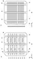
- FIG. 1 is a plan view from the light-receiving surface side of the configuration of the solar cell module 100.
- FIG. 2 is a plan view from the back side of the solar cell module 100.
- an orthogonal coordinate system including an x-axis, a y-axis, and a z-axis is defined.
- the x axis and the y axis are orthogonal to each other in the plane of the solar cell module 100.
- the z axis is perpendicular to the x axis and the y axis and extends in the thickness direction of the solar cell module 100.
- the positive directions of the x-axis, y-axis, and z-axis are each defined in the direction of the arrow in FIG. 1, and the negative direction is defined in the direction opposite to the arrow.
- the main plane arranged on the positive side of the z axis is the light receiving surface
- the z axis The main plane arranged on the negative direction side is the back surface.
- the positive direction side of the z-axis is referred to as “light-receiving surface side”
- the negative direction side of the z-axis is referred to as “back surface side”.
- the solar cell module 100 includes eleventh solar cells 10aa, collectively referred to as solar cells 10, ..., 84th solar cell 10hd, inter-group wiring member 14, group end wiring member 16, inter-cell wiring member 18, A termination wiring member 20 is included.
- the first non-power generation region 38a and the second non-power generation region 38b are arranged so as to sandwich the plurality of solar cells 10 in the y-axis direction. Specifically, the first non-power generation region 38 a is arranged on the positive side of the y axis with respect to the plurality of solar cells 10, and the second non-power generation region 38 b is on the y axis with respect to the plurality of solar cells 10. It is arranged on the negative direction side.
- the first non-power generation region 38 a and the second non-power generation region 38 b (hereinafter, sometimes collectively referred to as “non-power generation region 38”) have a rectangular shape and do not include the solar battery cell 10.
- the solar battery cell 10 is made of, for example, a semiconductor material such as crystalline silicon, gallium arsenide (GaAs), or indium phosphorus (InP).
- the structure of the solar battery cell 10 is not particularly limited, but here, as an example, it is assumed that crystalline silicon and amorphous silicon are stacked.
- FIGS. 3A to 3B are plan views showing the configuration of the solar battery cell 10.
- FIG. 3A shows the light receiving surface of the solar battery cell 10
- FIG. 3B shows the back surface of the solar battery cell 10.
- the photoelectric conversion layer 60 corresponds to the semiconductor material described above.
- the light receiving surface and the back surface of the photoelectric conversion layer 60 are configured by octagons in which long sides and short sides are alternately connected, but other shapes, for example, the short sides included in the octagon are non-linear. It may be formed by a quadrangle.
- a plurality of finger electrodes 52 extending in the x-axis direction are arranged in parallel to each other.
- the number of finger electrodes 52 is not limited to “9”.
- a plurality of, for example, three bus bar electrodes 50 that extend in the y-axis direction so as to intersect, for example, orthogonal to the plurality of finger electrodes 52 are arranged.
- the bus bar electrode 50 connects each of the plurality of finger electrodes 52.
- the bus bar electrode 50 and the finger electrode 52 are formed of, for example, silver paste.
- the inter-cell wiring member 18 is arranged so as to overlap each of the plurality of bus bar electrodes 50 from the positive side of the z axis.
- the bus bar electrode 50 and the inter-cell wiring member 18 are bonded with a conductive film adhesive.
- the inter-cell wiring member 18 is made of a metal such as silver or copper, and extends in the direction of another adjacent solar battery cell 10, that is, the y-axis direction. Therefore, it can be said that the bus bar electrode 50 is disposed between the light receiving surface of the photoelectric conversion layer 60 and the inter-cell wiring member 18.
- the bus bar electrode 50, the finger electrode 52, and the inter-cell wiring member 18 are disposed in the same manner as the light receiving surface of the photoelectric conversion layer 60.
- the number of bus bar electrodes 50 and inter-cell wiring members 18 are the same on the light receiving surface and the back surface of the photoelectric conversion layer 60, but the number of finger electrodes 52 is greater on the back surface than the light receiving surface of the photoelectric conversion layer 60. .
- the x-axis direction corresponds to the “first direction”
- the y-axis direction corresponds to the “second direction”.
- the bus bar electrode 50 is referred to as “another collecting electrode”.
- the plurality of solar cells 10 are arranged in a matrix on the xy plane.
- eight solar cells 10 are arranged in the x-axis direction, and four solar cells 10 are arranged in the y-axis direction.
- the number of the photovoltaic cells 10 arranged in the x-axis direction and the number of the photovoltaic cells 10 arranged in the y-axis direction are not limited to this.
- the four solar cells 10 arranged side by side in the y-axis direction are connected in series by the inter-cell wiring member 18 to form one solar cell group 12.
- the first solar cell group 12a is formed by connecting the eleventh solar cell 10aa, the twelfth solar cell 10ab, the thirteenth solar cell 10ac, and the fourteenth solar cell 10ad.
- Other solar cell groups 12, for example, the second solar cell group 12b to the eighth solar cell group 12h are formed in the same manner.
- the eight solar cell groups 12 are arranged in parallel in the x-axis direction.
- the solar cell group 12 corresponds to a string.
- the inter-cell wiring member 18 connects the bus bar electrode 50 on one light receiving surface side of the adjacent solar cells 10 and the bus bar electrode 50 on the other back surface side.
- the three inter-cell wiring members 18 for connecting the eleventh solar cell 10aa and the twelfth solar cell 10ab include the bus bar electrode 50 on the back surface side of the eleventh solar cell 10aa and the twelfth solar cell 10ab. Are electrically connected to the bus bar electrode 50 on the light receiving surface side.
- the inter-cell wiring member 18 is disposed so as to overlap the bus bar electrodes 50.
- Each of the seven inter-group wiring members 14 extends in the x-axis direction and is electrically connected to two adjacent solar cell groups 12 via the group end wiring member 16.
- Each is electrically connected to the inter-group wiring member 14 via the group end wiring member 16.
- the group end wiring member 16 is arranged in the same manner as the inter-cell wiring member 18 on the light receiving surface or the back surface of the solar battery cell 10.
- the termination wiring member 20 is connected to the first solar cell group 12a and the eighth solar cell group 12h located at both ends in the x-axis direction.
- the termination wiring member 20 connected to the first solar cell group 12a extends in the direction of the first non-power generation region 38a from the light receiving surface side of the eleventh solar cell 10aa.
- a pair of positive and negative lead wires (not shown) is connected to the termination wiring member 20.
- FIG. 4 is a cross-sectional view of the solar cell module 100 along the y-axis.
- FIG. 2 is a cross-sectional view taken along the line A-A ′ of FIG. 1.
- the solar cell module 100 includes an eleventh solar cell 10aa, a twelfth solar cell 10ab, a thirteenth solar cell 10ac, a fourteenth solar cell 10ad, an inter-group wiring member 14, and a group end.
- Wiring material 16, inter-cell wiring material 18, termination wiring material 20, take-out wiring 30, first protective member 40a, second protective member 40b, collectively referred to as protective member 40, and first sealing, collectively referred to as sealing member 42 A member 42a, a second sealing member 42b, and a terminal box 44 are included.
- the upper side in FIG. 4 corresponds to the back side, and the lower side corresponds to the light receiving side.
- the first protective member 40 a is disposed on the light receiving surface side of the solar cell module 100 and protects the surface of the solar cell module 100.
- the first protective member 40a is made of a light-transmitting and water-blocking glass, a light-transmitting plastic, or the like, and is formed in a rectangular plate shape.
- the 1st sealing member 42a is laminated
- the 1st sealing member 42a is arrange
- thermoplastic resins like resin sheets such as polyolefin, EVA, PVB (polyvinyl butyral), a polyimide, are used, for example.
- a thermosetting resin may be used.
- the first sealing member 42a is formed of a rectangular sheet material having translucency and having a surface having substantially the same dimensions as the xy plane of the first protection member 40a.
- the second sealing member 42b is laminated on the back side of the first sealing member 42a.
- the second sealing member 42b seals the plurality of solar cells 10, the inter-cell wiring member 18 and the like with the first sealing member 42a.
- the 2nd sealing member 42b can use the thing similar to the 1st sealing member 42a.
- the second sealing member 42b may be integrated with the first sealing member 42a by heating in the laminating / curing process.
- the second protective member 40b is laminated on the back side of the second sealing member 42b.
- the 2nd protection member 40b protects the back surface side of the solar cell module 100 as a back sheet.
- a resin film such as PET (polyethylene terephthalate), a laminated film having a structure in which an Al foil is sandwiched between resin films, and the like are used.
- the second protective member 40b is provided with an opening (not shown) penetrating in the z-axis direction.
- the terminal box 44 is formed in a rectangular parallelepiped shape, and is bonded from the back surface side of the second protective member 40b using an adhesive such as silicone so as to cover the opening (not shown) of the second protective member 40b.
- the lead-out wiring 30 is led to a bypass diode (not shown) stored in the terminal box 44.
- the terminal box 44 is arrange
- An Al frame frame may be attached around the solar cell module 100.
- a portion to which the bus bar electrode 50, the finger electrode 52, and the inter-cell wiring member 18 are connected is classified into a plurality. As shown in FIG. 3A, the classification of these parts includes a first area 70, a second area 72, and a third area 74.
- the first area 70 is an area provided around a portion where the inter-cell wiring member 18 is arranged in the finger electrodes 52 arranged on the end side in the y-axis direction among the plurality of finger electrodes 52.
- three first areas 70 are provided on the finger electrode 52 arranged on the most positive direction side of the y axis
- three first electrodes 70 are provided on the finger electrode 52 arranged on the most negative direction side of the y axis.
- the second area 72 is an area provided around the portion where the inter-cell wiring member 18 is arranged in the finger electrode 52 arranged at the center in the y-axis direction among the plurality of finger electrodes 52.
- three second areas 72 are provided on the finger electrode 52 arranged at the center in the y-axis direction.
- the third area 74 is an intercell wiring in the finger electrode 52 between the finger electrode 52 provided with the first area 70 and the finger electrode 52 provided with the second area 72 among the plurality of finger electrodes 52. This is an area provided around the portion where the material 18 is arranged.
- three third areas 74 are provided on the finger electrode 52 on the positive direction side of the y axis and three are provided on the finger electrode 52 on the negative direction side of the y axis.
- FIGS. 5A to 5B show a part of the solar battery cell 10 in detail.
- a plan view in which the first area 70 of FIG. 3A is enlarged is shown below FIG.
- the finger electrode 52 extending in the x-axis direction and the bus bar electrode 50 extending in the y-axis direction intersect at a portion where the inter-cell wiring member 18 is disposed.
- the width of the inter-cell wiring member 18 is wider than the width of the bus bar electrode 50, the width of the inter-cell wiring member 18 is, for example, about 1 mm to 3 mm, and the width of the bus bar electrode is, for example, 1 mm or less.
- the width in the y-axis direction of the finger electrode 52 is “ ⁇ ” in the portion where the inter-cell wiring member 18 is not arranged, and the y-axis direction of the finger electrode 52 in the portion where the inter-cell wiring member 18 is arranged.
- the width is “ ⁇ ”. Note that ⁇ > ⁇ . That is, in the finger electrode 52 in the first area 70, the width of the portion where the inter-cell wiring member 18 is disposed is larger than the width of the portion where the inter-cell wiring member 18 is not disposed.
- FIG. 5A shows a B-B ′ cross-sectional view in the plan view shown on the lower side.
- a bus bar electrode 50 and finger electrodes 52 are arranged on the positive side of the z-axis of the photoelectric conversion layer 60.
- the height in the z-axis direction of the finger electrode 52 is “c” in the portion where the inter-cell wiring member 18 is not disposed, and the z-axis direction of the finger electrode 52 in the portion where the inter-cell wiring member 18 is disposed.
- the height of “a” is “a”. Note that a> c.
- the height from the photoelectric conversion layer 60 in the portion where the inter-cell wiring material 18 is disposed is high from the photoelectric conversion layer 60 in the portion where the inter-cell wiring material 18 is not disposed. Higher than that.
- the height of the bus bar electrode 50 in the z-axis direction is “r”. Note that a> r. That is, in the finger electrode 52 in the first area 70, the height from the photoelectric conversion layer 60 at the portion where the inter-cell wiring member 18 is disposed is higher than the height of the bus bar electrode 50 from the photoelectric conversion layer 60. With such a configuration, the inter-cell wiring member 18 is connected mainly to the positive direction side of the finger electrode 52 in the z-axis direction.
- the conductive film adhesive is used for this connection, and the conductive film adhesive is a polymer resin containing an acrylic polymer and a thermosetting resin. The conductive film adhesive also contains conductive particles and has anisotropic conductivity.
- the bonding area between the bus bar electrode 50 and the inter-cell wiring member 18 is reduced, and the connection between the bus bar electrode 50 and the inter-cell wiring member 18 is weakened.
- the finger electrode 52 and the inter-cell wiring member 18 are connected, an increase in electrical resistance is suppressed and a decrease in conductivity is suppressed.
- the bus bar electrode 50 and the finger electrode 52 are formed on the light receiving surface of the photoelectric conversion layer 60 by screen printing. When the finger electrode 52 is formed by screen printing, the height of the finger electrode 52 increases as the width of the finger electrode 52 increases. The same applies to the bus bar electrode 50.
- the bus-bar electrode 50 and the finger electrode 52 are shown as another structure, these may be formed integrally.
- FIG. 5B is an enlarged plan view of the second area 72 in FIG. 3A.
- the finger electrode 52 extending in the x-axis direction and the bus bar electrode 50 extending in the y-axis direction intersect at a portion where the inter-cell wiring member 18 is disposed.
- the width in the y-axis direction of the finger electrode 52 is “ ⁇ ” in the portion where the inter-cell wiring member 18 is not arranged, and the y-axis direction of the finger electrode 52 in the portion where the inter-cell wiring member 18 is arranged.
- the width is “ ⁇ ”. Note that ⁇ > ⁇ .
- the width of the portion where the inter-cell wiring member 18 is disposed is narrower than the width of the portion where the inter-cell wiring member 18 is not disposed.
- FIG. 5B The upper side of FIG. 5B is a cross-sectional view taken along the line C-C ′ in the plan view shown on the lower side.
- a bus bar electrode 50 and finger electrodes 52 are arranged on the positive side of the z-axis of the photoelectric conversion layer 60.
- the height in the z-axis direction of the finger electrode 52 is “c” in the portion where the inter-cell wiring member 18 is not disposed, and the z-axis direction of the finger electrode 52 in the portion where the inter-cell wiring member 18 is disposed. Is "b". Note that c> b.
- the height from the photoelectric conversion layer 60 in the portion where the inter-cell wiring member 18 is disposed is high from the photoelectric conversion layer 60 in the portion where the inter-cell wiring member 18 is not disposed. Lower than that.
- the height of the bus bar electrode 50 in the z-axis direction is “r”. Note that r> b. That is, in the finger electrode 52 in the second area 72, the height from the photoelectric conversion layer 60 at the portion where the inter-cell wiring member 18 is disposed is lower than the height of the bus bar electrode 50 from the photoelectric conversion layer 60. With such a configuration, the inter-cell wiring member 18 is connected mainly to the positive direction side of the z-axis of the bus bar electrode 50 via the conductive film adhesive. The bus bar electrode 50 and the inter-cell wiring member 18 are bonded, but the finger electrode 52 and the inter-cell wiring member 18 are not bonded. This is a configuration for adjusting the adhesive strength in the first area 70.
- the height of the finger electrode 52 decreases as the width of the finger electrode 52 decreases.
- the height of the finger electrode 52 in the first area 70 is the same as that in the second area 72. It is higher than the height of the electrode 52.
- the wiring member 18 is arranged at a location where the heights of the finger electrodes 52 are different.
- the inter-cell wiring member 18 has different heights of the finger electrodes 52. You may arrange
- the width in the y-axis direction of the finger electrode 52 is “ ⁇ ” in a portion where the inter-cell wiring member 18 is not disposed and a portion where the inter-cell wiring member 18 is disposed. That is, in the third area 74, the width of the finger electrode 52 is constant regardless of whether the inter-cell wiring member 18 is a portion where the inter-cell wiring member 18 is disposed or not.
- the height in the z-axis direction of the finger electrode 52 is “c” in the portion where the inter-cell wiring member 18 is not disposed and the portion where the inter-cell wiring member 18 is disposed. That is, in the second area 72, the height of the finger electrode 52 is constant regardless of whether the inter-cell wiring member 18 is a portion where it is disposed or not.
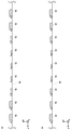
- FIG. 6A to 6B are cross-sectional views of the finger electrode 52 along the y-axis. This is an E-E ′ sectional view of FIG.
- a plurality of finger electrodes 52 are arranged side by side in the y-axis direction.
- the height from the photoelectric conversion layer 60 is set to “a” in the finger electrode 52 arranged on the most positive direction side of the y-axis and the finger electrode 52 adjacent thereto.
- the height from the photoelectric conversion layer 60 is also set to “a” in the finger electrode 52 arranged on the most negative direction side of the y-axis and the finger electrode 52 adjacent thereto. That is, the first area 70 is provided for the four finger electrodes 52.
- the height from the photoelectric conversion layer 60 is set to “b” in the three finger electrodes 52 including the central finger electrode 52 in the y-axis direction. That is, the second area 72 is provided for the three finger electrodes 52. Further, in the remaining two finger electrodes 52, the height from the photoelectric conversion layer 60 is set to “c”. That is, the third area 74 is provided for the two finger electrodes 52. In this way, the height is defined by the number of types smaller than the value obtained by dividing the number of finger electrodes 52 by two. That is, in the plurality of finger electrodes 52, the height from the photoelectric conversion layer 60 in the portion where the inter-cell wiring member 18 is disposed is increased stepwise from the center in the y-axis direction toward the end.
- FIG. 6 (b) is an example different from FIG. 6 (a).
- FIG. 6B is also shown in the same manner as FIG.
- the height from the photoelectric conversion layer 60 is set to “a” in the finger electrode 52 arranged on the most positive direction side of the y axis and the finger electrode 52 arranged on the most negative direction side of the y axis.
- the height from the photoelectric conversion layer 60 is set to “b” in the finger electrode 52 at the center in the y-axis direction.
- the height from the photoelectric conversion layer 60 is set to “c”.
- the height from the photoelectric conversion layer 60 is limited to these “3” types.
- FIG. 6A the height from the photoelectric conversion layer 60 is limited to these “3” types.
- the height from the photoelectric conversion layer 60 is gradually increased as the finger electrode 52 is closer to the end in the y-axis direction. That is, the height of each finger electrode 52 from the center finger electrode 52 in the y-axis direction toward the finger electrode 52 arranged on the most positive side in the y-axis is “b”, “d”, “c”. , “E”, and “a”.
- the example of a different structure of the finger electrode 52 is demonstrated.
- the cross-sectional area of the finger electrode 52 in such a part is made smaller than the cross-sectional area of the finger electrode 52 in the other part.
- the electrical resistance may increase and the conductivity may be reduced.
- a configuration for maintaining the conductivity of the finger electrode 52 even when the finger electrode 52 is thin and low will be described.
- FIGS. 7A to 7B are plan views showing a part of the finger electrode 52 in detail.
- FIG. 7A shows another configuration of the finger electrode 52 in the second area 72.
- the finger electrode 52 extends in the positive direction from the negative direction of the x axis, thereby reaching the portion where the inter-cell wiring member 18 is disposed.
- a branch point 80 is defined in the reached portion, and the finger electrode 52 is branched into the first branch electrode 82, the second branch electrode 84, and the third branch electrode 86 at the branch point 80.
- the respective cross-sectional areas are the finger electrodes.
- the sum of the cross-sectional areas of the first branch electrode 82, the second branch electrode 84, and the third branch electrode 86 is formed to be equal to or larger than the cross-sectional area of the finger electrode 52.
- the first branch electrode 82, the second branch electrode 84, and the third branch electrode 86 are connected to the bus bar electrode 50.
- first branch electrode 82, the second branch electrode 84, and the third branch electrode 86 extend from the bus bar electrode 50 in the positive direction of the x-axis, and they merge at a junction 88. That is, the finger electrode 52 is branched into a plurality of portions at the portion where the inter-cell wiring member 18 is disposed.
- branch point 80 and the junction point 88 are distinguished for convenience of explanation, they are actually configured in the same manner, and they may be arranged in reverse.
- the positive direction side of the x-axis from the junction point 88 is a portion where the inter-cell wiring member 18 is not disposed, and the finger electrode 52 is disposed.
- each of the first branch electrode 82, the second branch electrode 84, and the third branch electrode 86 is larger than the electric resistance of the finger electrode 52, but the first branch electrode 82, the second branch electrode 84, and the third branch.
- FIG. 7B shows a case where the configuration of FIG. 7A is applied to the first area 70.
- the finger electrode 52, the branch point 80, the first branch electrode 82, the second branch electrode 84, the third branch electrode 86, and the junction point 88 are configured in the same manner as in FIG. However, since the height of each of the first branch electrode 82, the second branch electrode 84, and the third branch electrode 86 is higher than the height of the finger electrode 52, the respective cross-sectional areas are larger than the cross-sectional areas of the finger electrodes 52. Increased.
- each of the first branch electrode 82, the second branch electrode 84, and the third branch electrode 86 is thicker than the finger electrode 52. Note that the finger electrode 52 is branched into a plurality of portions other than the first area 70 and the second area 72 and also in a portion where the bus bar electrode 50 and the finger electrode 52 intersect.
- the branch point 80 and the junction point 88 are hidden by the inter-cell wiring member 18 when the solar battery cell 10 is viewed from the positive direction side of the z-axis.
- the branch point 80 or the junction point 88 may protrude from the inter-cell wiring member 18 when the solar battery cell 10 is viewed from the positive direction side of the z axis. Even in such a configuration, the effect of controlling the adhesive force is sufficiently exhibited as compared with the case where the branch point 80 and the junction point 88 are hidden by the inter-cell wiring member 18.
- FIGS. 8A and 8B are plan views showing another example of part of the finger electrode 52.
- the finger electrode 52, the branch point 80, the first branch electrode 82, the second branch electrode 84, the third branch electrode 86, and the junction point 88 are configured in the same manner as in FIG.
- the first branch electrode 82 and the third branch electrode 86 include an arc shape, which is different from the conventional configuration configured by a combination of linear shapes.
- the finger electrode 52 is branched from the branch point 80 into four parts, a first branch electrode 82, a second branch electrode 84, a third branch electrode 86, and a fourth branch electrode 90, and these are joined together. Join at point 88. That is, the number of branching of the finger electrodes 52 is not limited to “3”.
- FIGS. 9A to 9E are other views showing a part of the solar battery cell 10 of FIG. 3A in detail. 9 (a)-(b) are the same as FIGS. 5 (a)-(b). Here, the direction of a sectional view to be described later is shown.
- FIGS. 9C to 9D are F-F ′ cross-sectional views in which the first area 70 of FIG. 9A is enlarged.
- the conductive film adhesive 62 is disposed on the solar battery cell 10, and the inter-cell wiring member 18 is further disposed thereon, and is fixed by thermocompression bonding.
- the conductive film adhesive 62 is once melted in thermocompression bonding and moved in the z-axis direction to be solidified as shown in FIGS. 9 (c) to 9 (d).
- FIGS. 9 (c) to 9 (d) the arrangement of the conductive film adhesive 62 after thermocompression bonding is as shown in FIG. d) and so on.
- the inter-cell wiring member 18 is supported by the finger electrodes 52 and the height of the finger electrodes 52 in the z-axis direction is increased to “a”. Therefore, the space between the inter-cell wiring member 18 and the photoelectric conversion layer 60 and the space where the finger electrodes 52 are not disposed is widened. Thereby, an area where the inter-cell wiring member 18 or the photoelectric conversion layer 60 and the conductive film adhesive 62 are bonded is reduced.
- FIG. 9E is a G-G ′ sectional view in which the second area 72 of FIG. 9B is enlarged.
- the conductive film adhesive 62 is melted once in the thermocompression bonding and moves in the z-axis direction to be in a state as shown in FIG.
- the conductive film adhesive 62 is also disposed between the inter-cell wiring member 18 and the finger electrode 52, and the height of the inter-cell wiring member 18 from the photoelectric conversion layer 60 is “r”.
- the height of the finger electrode 52 in the z-axis direction is reduced to “b”. Therefore, the space between the inter-cell wiring member 18 and the photoelectric conversion layer 60 and the space where the finger electrodes 52 are not arranged is narrow. Thereby, an area where the inter-cell wiring member 18 and the photoelectric conversion layer 60 are bonded to the conductive film adhesive 62 is increased.
- the bonding area of the conductive film adhesive 62 is smaller in the former than the latter, that is, in the first area 70 than in the second area 72. Become. Therefore, the adhesive force is smaller in the first area 70 than in the second area 72.
- the manufacturing method of the solar cell module 100 is demonstrated.
- the photoelectric conversion layer 60 is prepared.
- the plurality of finger electrodes 52 extending in the x-axis direction and the plurality of bus bar electrodes 50 extending in the y-axis direction are formed, whereby the solar battery cell 10 is formed.
- the shape of the finger electrode 52 is as described above.
- the 1st protection member 40a, the 1st sealing member 42a, the photovoltaic cell 10, the 2nd sealing member 42b, and the 2nd protection member 40b are piled up in order toward the negative direction from the positive direction of the z axis. Thereby, a laminated body is produced
- the conductive film adhesive is drawn out from the roll of the conductive film adhesive wound around the reel member and used to bond the surface of the solar cell 10 and the inter-cell wiring member 18. . Moreover, thermocompression bonding is performed for adhesion.
- a laminate curing process is performed on the laminate.
- air is extracted from the laminated body, and heated and pressurized to integrate the laminated body.
- the terminal box 44 is attached to the second protective member 40b with an adhesive.
- the bus bar electrode 50 and the finger electrode 52 are formed by screen printing.
- screen printing a screen plate having openings corresponding to the patterns of the bus bar electrodes 50 and the finger electrodes 52 to be formed is used.
- the silver paste is put on the screen plate and the silver paste is slid with a squeegee, the silver paste passes through the opening of the screen plate and is transferred to the photoelectric conversion layer 60.
- FIG. 10 is a plan view showing a screen plate including the finger electrode 52. This is shown in the same way as in FIG. 7 (a), but the printing direction 92 for screen printing is shown.
- the printing direction 92 is determined so as to go from the negative direction of the x axis to the positive direction.
- the thickness of the finger electrode 52 toward the branch point 80 is “ ⁇ ”.
- the first branch electrode 82, the second branch electrode 84, and the third branch electrode 86 are joined at the junction 88, so that the first branch electrode 82, the second branch electrode 84, and the third branch electrode 86 are joined. Silver paste from is collected at the confluence 88.
- the amount of silver paste at the junction 88 tends to be larger than the amount of silver paste at the branch point 80.
- the thickness of the finger electrode 52 from the junction point 88 in the positive direction of the x-axis is also “ ⁇ ”
- the thickness of the finger electrode 52 in this portion is at the branch point 80. It becomes higher than the height of the finger electrode 52 which goes.
- the thickness of the finger electrode 52 in the positive direction of the x-axis from the junction 88 is set to “ ⁇ ” in a certain range in the screen plate. Note that ⁇ ⁇ .
- the opening of the screen plate in the screen printing is preferably thinner than before branching over a range of 1 mm to 20 mm, for example, about 5 mm after the finger electrodes 52 merge.
- the height of the portion where the inter-cell wiring member 18 can be arranged is the finger electrode in the central portion in the same direction.
- the adhesion area of the bus-bar electrode 50 and the intercell wiring material 18 can be made small.
- the connection of the photovoltaic cell 10 and the intercell wiring material 18 can be weakened.
- the stress applied to the solar battery cell 10 can be reduced.
- the durability of the solar battery cell 10 can be improved.
- the durability of the solar battery module 100 can also be improved.
- the height of the finger electrode 52 may be continuously changed from the center in the direction in which the inter-cell wiring member 18 extends toward the end, or the finger electrode 52 close to the end has a particularly high configuration.
- the types of height of the finger electrodes 52 are limited to several types. The design and manufacture of the cell 10 can be simplified.
- the adhesive force between the solar battery cell 10 and the inter-cell wiring member 18 can be adjusted in detail.
- the height of the portion where the inter-cell wiring member 18 can be disposed is higher than the height of the other portions.
- the height of the part other than can be lowered.
- the finger electrode 52 of the said part can be made thin.
- photoelectric conversion efficiency can be improved.
- the second electrode 72 can be divided into a plurality of portions in the second area 72 by branching the finger electrode 52 in a portion where the inter-cell wiring member 18 can be disposed. Also, the same conductivity as that of the portion other than the second area 72 can be secured. In addition, since the finger electrode 52 is branched into a plurality of portions where the inter-cell wiring member 18 can be disposed, the effect of weakening the adhesive force between the inter-cell wiring member 18 and the finger electrode 52 in the first area 70 is sufficiently exhibited. be able to.
- the bus bar electrode 50 is lower than the height of the portion where the inter-cell wiring material 18 can be disposed in the finger electrode 52 disposed on the end side in the direction in which the inter-cell wiring material 18 extends, the bus bar electrode 50 and the cell The adhesion area with the interwiring material 18 can be reduced. Further, since the bus bar electrode 50 is higher than the height of the portion where the inter-cell wiring member 18 can be disposed in the finger electrode 52 disposed at the center in the direction in which the inter-cell wiring member 18 extends, the adhesive strength can be adjusted. Moreover, since the thickness of the opening formed in the screen plate used for screen printing is made thinner than the thickness before branching after the joining of the finger electrodes 52, the thickness of the finger electrodes 52 after printing is reduced. Can be uniform.
- the solar battery cell 10 of an aspect of the present invention includes a photoelectric conversion layer 60 and a plurality of finger electrodes 52 that are disposed on the surface of the photoelectric conversion layer 60 and extend in the first direction.
- the plurality of finger electrodes 52 are arranged in a second direction in which the inter-cell wiring member 18 that can be disposed on the surface of the photoelectric conversion layer 60 extends, and in a second direction intersecting the first direction.
- the height from the photoelectric conversion layer 60 of the portion where the inter-cell wiring member 18 can be arranged in the finger electrode 52 arranged on the end side in the second direction is the center in the second direction.
- the height from the photoelectric conversion layer 60 in the part where the inter-cell wiring member 18 can be arranged is higher.
- the height from the photoelectric conversion layer 60 where the inter-cell wiring member 18 can be disposed is higher as the inter-cell wiring member 18 is closer to the end in the second direction.
- the height from the photoelectric conversion layer 60 where the inter-cell wiring member 18 can be disposed may be increased stepwise from the center in the second direction toward the end. .
- the height from the photoelectric conversion layer 60 of the portion where the inter-cell wiring member 18 can be arranged is It is higher than the height from the photoelectric conversion layer 60 in a portion other than the portion where the inter-wiring member 18 can be disposed, and (2) the inter-cell wiring member 18 is disposed in the finger electrode 52 disposed in the center portion in the second direction.
- the height from the photoelectric conversion layer 60 of the part which can be done is lower than the height from the photoelectric conversion layer 60 of parts other than the part which can arrange
- Each of the plurality of finger electrodes 52 may be branched into a plurality of portions where the inter-cell wiring member 18 can be disposed.
- a bus bar electrode 50 disposed between the surface of the photoelectric conversion layer 60 and the inter-cell wiring member 18 and extending in the second direction may be further provided.
- the height of the bus bar electrode 50 from the photoelectric conversion layer 60 is (1) from the portion of the photoelectric conversion layer 60 where the inter-cell wiring member 18 can be disposed in the finger electrode 52 disposed on the end side in the second direction. (2) In the finger electrode 52 disposed in the center portion in the second direction, the height from the photoelectric conversion layer 60 in the portion where the inter-cell wiring member 18 can be disposed is higher.
- This solar cell module 100 is a solar cell module 100 including a plurality of solar cells 10 and an inter-cell wiring member 18 that electrically connects adjacent solar cells 10, and the plurality of solar cells 10.
- Each includes a photoelectric conversion layer 60 and a plurality of finger electrodes 52 disposed on the surface of the photoelectric conversion layer 60 and extending in the first direction.
- the plurality of finger electrodes 52 are arranged in a second direction in which the inter-cell wiring member 18 disposed on the surface of the photoelectric conversion layer 60 extends and intersects the first direction.
- the height from the photoelectric conversion layer 60 of the portion where the inter-cell wiring member 18 is arranged in the finger electrode 52 arranged on the end side in the second direction is the center in the second direction.
- the height from the photoelectric conversion layer 60 in the portion where the inter-cell wiring member 18 is arranged is higher.
- Still another aspect of the present invention is a method for manufacturing a solar battery cell 10.
- This method includes the steps of preparing the photoelectric conversion layer 60 and forming a plurality of finger electrodes 52 extending in the first direction on the surface of the photoelectric conversion layer 60.
- the plurality of finger electrodes 52 are arranged in a second direction in which the inter-cell wiring member 18 that can be disposed on the surface of the photoelectric conversion layer 60 extends, and in a second direction intersecting the first direction.
- the height from the photoelectric conversion layer 60 of the portion where the inter-cell wiring member 18 can be arranged in the finger electrode 52 arranged on the end side in the second direction is the center in the second direction.
- the height from the photoelectric conversion layer 60 in the part where the inter-cell wiring member 18 can be arranged is higher.
- each of the plurality of finger electrodes 52 is branched into a plurality of portions where the inter-cell wiring member 18 can be disposed.
- each finger electrode 52 in the screen plate in the screen printing before branching is thicker than the thickness after joining. It will be lost.
- Example 2 is related to a solar cell module in which a plurality of solar cells are arranged in the same manner as Example 1. Finger electrodes and bus bar electrodes are arranged on the light receiving surface and back surface of the solar battery cell in Example 1, and an inter-cell wiring material is arranged so as to overlap the bus bar electrodes. On the other hand, the bus bar electrode is not disposed on the light receiving surface and the back surface of the solar battery cell in Example 2, and the finger electrode is disposed. Also in such a solar cell, the stress which a solar cell receives becomes large in the edge part side of the solar cell in the direction where the wiring material between cells extends.
- the solar cell module 100 according to the second embodiment is of the same type as that shown in FIGS. Further, the solar battery cell 10 according to Example 2 has a configuration in which the bus bar electrode 50 is omitted from FIGS. 3A to 3B. Below, it demonstrates focusing on a difference.
- FIGS. 11A to 11B are plan views showing a part of the finger electrode 52 in detail.
- FIG. 11A shows the configuration of the finger electrode 52 in the second area 72. This is shown in the same manner as FIG. 7A, although the bus bar electrode 50 is omitted.
- FIG. 11B shows the configuration of the finger electrode 52 in the first area 70. This also shows the same as in FIG. 7B, although the bus bar electrode 50 is omitted. In addition, it is comprised similarly also in the part other than the 2nd area 72, and the part which the bus-bar electrode 50 and the finger electrode 52 cross
- the bus bar electrode 50 since the bus bar electrode 50 is not disposed, the stress can be reduced even in the solar battery cell 10 in which only the finger electrode 52 is disposed. Further, since the finger electrode 52 is branched into a plurality of parts, in the output measurement process in the manufacturing process of the solar battery cell 10, even if the bus bar electrode 50 is not disposed, the finger electrode 52 and the measurement terminal of the measuring device are contacted. Easy to do. For this reason, the test of the photovoltaic cell 10 can be easily performed.
- Example 3 is related with the solar cell module by which the several photovoltaic cell is arrange
- the height of the finger electrodes has been increased on both end sides of the solar cell in the direction in which the inter-cell wiring member extends. This is because the stress that the solar cell receives on the end side increases.
- the inter-cell wiring member electrically connects two adjacent solar cells. Therefore, the stress on the end side closer to the adjacent solar cell out of both end sides in the direction in which the inter-cell wiring member extends becomes larger than the stress on the far end side.
- Example 3 the height of the finger electrode is increased on the end side closer to the adjacent solar battery cell than the central part of the solar battery cell in the direction in which the inter-cell wiring member extends.
- the solar cell module 100 according to Example 3 is the same type as that shown in FIGS. Below, it demonstrates focusing on a difference.
- the inter-cell wiring member 18 extends in the y-axis direction, and in particular, toward the positive direction side of the y-axis where another adjacent solar cell 10 (not shown) is arranged. It extends from 10 forward.
- the first area 70 is a periphery of a portion where the inter-cell wiring member 18 is arranged in the finger electrode 52 arranged on the end side in the positive direction of the y-axis among the plurality of finger electrodes 52. Provided.
- the third area 74 is provided around the portion of the plurality of finger electrodes 52 other than the finger electrode 52 provided with the first area 70 where the inter-cell wiring member 18 is disposed. For this reason, among the plurality of finger electrodes 52, the third area 74 is provided around the portion where the inter-cell wiring member 18 is arranged in the finger electrode 52 arranged on the end side in the negative direction of the y-axis. Since the height of the finger electrode 52 in each of the first area 70 and the third area 74 is the same as before, description thereof is omitted here.
- FIG. 12 (b) shows a pattern different from FIG. 12 (a).
- the arrangement of the first areas 70 in FIG. 12B is the same as that in FIG.
- the second area 72 is the periphery of the portion where the inter-cell wiring member 18 is disposed in the finger electrode 52 disposed in the central portion in the y-axis direction among the plurality of finger electrodes 52.
- three second areas 72 are provided on the finger electrode 52 arranged at the center in the y-axis direction. Since the height of the finger electrode 52 in the second area 72 is the same as before, the description thereof is omitted here. Moreover, since the back surface of the photovoltaic cell 10 should just be comprised similarly, description is abbreviate
- the height from the photoelectric conversion layer 60 is higher in the finger electrode 52 disposed on one end side in the direction in which the inter-cell wiring member 18 extends than in the finger electrode 52 disposed in the central portion. Therefore, the stress applied to the solar battery cell 10 on one end side can be reduced. In addition, since the height from the photoelectric conversion layer 60 is increased in the finger electrodes 52 arranged on one end side, the number of finger electrodes 52 that increase the height can be reduced. Further, since the number of finger electrodes 52 that increase the height decreases, the amount of silver paste used can be reduced.
- similar to the adjacent photovoltaic cell 10 since it makes it higher than the finger electrode 52 arrange
- the outline of this example is as follows.
- the height from the photoelectric conversion layer 60 of the portion where the inter-cell wiring member 18 can be disposed in the finger electrode 52 disposed on one end side in the second direction is the second.
- the height from the photoelectric conversion layer 60 of the part where the inter-cell wiring member 18 can be arranged may be higher.
- the inter-cell wiring member 18 is electrically connected to the present solar cell 10 and another solar cell 10 adjacent to the present solar cell 10, and is disposed on one end side in the second direction.
- the finger electrode 52 may be a finger electrode 52 disposed on the end side closer to another solar battery cell 10.
- a bus bar electrode is provided as in FIG. 3 .
- the present embodiment may be applied to a solar battery cell that does not have a bus bar electrode as in FIG. Specifically, even when the bus bar electrode is not provided, three finger electrodes arranged on the most positive side of the y axis may be provided with three areas with high finger electrode heights.
- the inter-cell wiring member 18 and the upper surface of the finger electrode 52 are electrically conductive film adhesive 62.
- the part which contacts directly without going through is increased.
- the conductive film adhesive 62 is melted by heating, it moves in the z-axis direction and further spreads in the y-axis direction between the surface of the solar battery cell 10 and the inter-cell wiring member 18. It is greatly influenced by the distance. That is, the conductive film adhesive 62 spreads in the second area 72 where the height of the finger electrode 52 is lower than the area where the conductive film adhesive 62 spreads in the first area 70 where the height of the finger electrode 52 is high. The area is larger. Therefore, the adhesive force can be made smaller in the first area 70 than in the second area 72.
- the finger electrode 52 is formed by screen printing, and the height of the finger electrode 52 is increased as the width of the finger electrode 52 is increased. That is, the height of the finger electrode 52 is adjusted by adjusting the thickness of the finger electrode 52.
- the present invention is not limited thereto.
- the height of the finger electrode 52 may be adjusted without adjusting the thickness of the finger electrode 52 by executing screen printing a plurality of times. At that time, the same screen plate may be used a plurality of times, or different screen plates may be used depending on the number of times of printing. According to this modification, the degree of freedom of configuration can be increased.
- the stress applied to the solar battery cell can be reduced.
Landscapes
- Engineering & Computer Science (AREA)
- Condensed Matter Physics & Semiconductors (AREA)
- Physics & Mathematics (AREA)
- Electromagnetism (AREA)
- General Physics & Mathematics (AREA)
- Computer Hardware Design (AREA)
- Microelectronics & Electronic Packaging (AREA)
- Power Engineering (AREA)
- Life Sciences & Earth Sciences (AREA)
- Sustainable Development (AREA)
- Sustainable Energy (AREA)
- Manufacturing & Machinery (AREA)
- Photovoltaic Devices (AREA)
Abstract
Selon l'invention, une pluralité d'électrodes de doigt (52) sont disposées sur une surface d'une couche de conversion photoélectrique (60) et s'étendent dans une première direction. Les électrodes de doigt (52) sont alignées les unes aux autres dans une seconde direction dans laquelle un matériau de câblage entre cellules (18) peut être disposé sur la surface de la couche de conversion photoélectrique (60). Dans une électrode de doigt (52) disposée du côté d'une section d'extrémité dans la seconde direction, ladite électrode de doigt faisant partie des électrodes de doigt (52), la hauteur d'une partie sur laquelle le matériau de câblage entre cellules (18) peut être disposé, ladite hauteur étant mesurée par rapport à la couche de conversion photoélectrique (60), est supérieure à la hauteur d'une partie sur laquelle le matériau de câblage entre cellules (18) peut être disposé dans une électrode de doigt (52) disposée au niveau d'une section centrale dans la seconde direction, ladite hauteur étant mesurée par rapport à la couche de conversion photoélectrique (60).
Priority Applications (2)
| Application Number | Priority Date | Filing Date | Title |
|---|---|---|---|
| JP2018507808A JP6706849B2 (ja) | 2016-03-30 | 2016-09-30 | 太陽電池セル、太陽電池モジュール、太陽電池セルの製造方法 |
| US16/146,607 US10797186B2 (en) | 2016-03-30 | 2018-09-28 | Solar cell, solar cell module, and solar cell manufacturing method in which wiring member is connected to surface |
Applications Claiming Priority (2)
| Application Number | Priority Date | Filing Date | Title |
|---|---|---|---|
| JP2016069263 | 2016-03-30 | ||
| JP2016-069263 | 2016-03-30 |
Related Child Applications (1)
| Application Number | Title | Priority Date | Filing Date |
|---|---|---|---|
| US16/146,607 Continuation US10797186B2 (en) | 2016-03-30 | 2018-09-28 | Solar cell, solar cell module, and solar cell manufacturing method in which wiring member is connected to surface |
Publications (1)
| Publication Number | Publication Date |
|---|---|
| WO2017168474A1 true WO2017168474A1 (fr) | 2017-10-05 |
Family
ID=59963595
Family Applications (1)
| Application Number | Title | Priority Date | Filing Date |
|---|---|---|---|
| PCT/JP2016/004425 WO2017168474A1 (fr) | 2016-03-30 | 2016-09-30 | Cellule de batterie solaire, module solaire, et procédé de fabrication de cellule de batterie solaire |
Country Status (3)
| Country | Link |
|---|---|
| US (1) | US10797186B2 (fr) |
| JP (1) | JP6706849B2 (fr) |
| WO (1) | WO2017168474A1 (fr) |
Cited By (3)
| Publication number | Priority date | Publication date | Assignee | Title |
|---|---|---|---|---|
| CN109037363A (zh) * | 2018-07-24 | 2018-12-18 | 浙江爱旭太阳能科技有限公司 | 具有防断栅功能的晶硅太阳能电池的正电极 |
| KR20210037697A (ko) * | 2018-07-24 | 2021-04-06 | 저지앙 아이코 솔라 에너지 테크놀로지 컴퍼니., 리미티드. | 양전극 중공 성형을 위한 결정성 실리콘 태양 전지 스크린 |
| CN113302746A (zh) * | 2018-11-27 | 2021-08-24 | 法国原子能及替代能源委员会 | 光伏电池和光伏链及相关的制造方法 |
Families Citing this family (1)
| Publication number | Priority date | Publication date | Assignee | Title |
|---|---|---|---|---|
| CN115207146A (zh) * | 2022-07-13 | 2022-10-18 | 通威太阳能(合肥)有限公司 | 一种施胶方法以及施胶系统 |
Citations (9)
| Publication number | Priority date | Publication date | Assignee | Title |
|---|---|---|---|---|
| JPH09169103A (ja) * | 1995-12-19 | 1997-06-30 | Murata Mfg Co Ltd | スクリーン印刷版 |
| JP2003218373A (ja) * | 2002-01-22 | 2003-07-31 | Sharp Corp | 太陽電池、その製造方法および製造器具 |
| JP2004014566A (ja) * | 2002-06-03 | 2004-01-15 | Sharp Corp | 太陽電池およびその製造方法 |
| JP2007214455A (ja) * | 2006-02-10 | 2007-08-23 | Sharp Corp | 太陽電池の製造方法および太陽電池製造用スクリーンマスク |
| JP2008263163A (ja) * | 2007-03-19 | 2008-10-30 | Sanyo Electric Co Ltd | 太陽電池モジュール |
| WO2012009809A1 (fr) * | 2010-07-23 | 2012-01-26 | Cyrium Technologies Incorporated | Cellule solaire à motif de quadrillage fractionné |
| JP2013045951A (ja) * | 2011-08-25 | 2013-03-04 | Sanyo Electric Co Ltd | 太陽電池および太陽電池モジュール |
| WO2013042241A1 (fr) * | 2011-09-22 | 2013-03-28 | 三洋電機株式会社 | Procédé de fabrication d'un dispositif photovoltaïque |
| JP2015139944A (ja) * | 2014-01-29 | 2015-08-03 | パナソニックIpマネジメント株式会社 | スクリーン印刷装置及び電子部品実装システム並びにスクリーン印刷方法 |
Family Cites Families (10)
| Publication number | Priority date | Publication date | Assignee | Title |
|---|---|---|---|---|
| JP3661836B2 (ja) * | 1999-04-05 | 2005-06-22 | シャープ株式会社 | 太陽電池の製造方法 |
| JP3838979B2 (ja) * | 2001-03-19 | 2006-10-25 | 信越半導体株式会社 | 太陽電池 |
| CN102349166A (zh) * | 2009-03-10 | 2012-02-08 | 三洋电机株式会社 | 太阳能电池的制造方法和太阳能电池 |
| JP5874011B2 (ja) * | 2011-01-28 | 2016-03-01 | パナソニックIpマネジメント株式会社 | 太陽電池及び太陽電池モジュール |
| TWI434427B (zh) * | 2011-04-08 | 2014-04-11 | Gintech Energy Corp | 光伏面板及形成光伏面板之導電通道的方法 |
| JP5903550B2 (ja) * | 2011-07-28 | 2016-04-13 | パナソニックIpマネジメント株式会社 | 太陽電池、太陽電池モジュール、太陽電池の製造方法 |
| WO2013073045A1 (fr) * | 2011-11-18 | 2013-05-23 | 三洋電機株式会社 | Cellule solaire et procédé de production pour cellule solaire |
| DE112012006596T5 (de) * | 2012-06-29 | 2015-04-02 | Sanyo Electric Co., Ltd. | Solarzellenmodul und Verfahren zum Fertigen eines Solarzellenmoduls |
| JP2015528645A (ja) * | 2012-09-17 | 2015-09-28 | アイメック・ヴェーゼットウェーImec Vzw | めっき金属層のシリコンへの接着の改良方法 |
| US9806206B2 (en) * | 2015-04-28 | 2017-10-31 | International Business Machines Corporation | Optimized grid design for concentrator solar cell |
-
2016
- 2016-09-30 JP JP2018507808A patent/JP6706849B2/ja not_active Expired - Fee Related
- 2016-09-30 WO PCT/JP2016/004425 patent/WO2017168474A1/fr active Application Filing
-
2018
- 2018-09-28 US US16/146,607 patent/US10797186B2/en active Active
Patent Citations (9)
| Publication number | Priority date | Publication date | Assignee | Title |
|---|---|---|---|---|
| JPH09169103A (ja) * | 1995-12-19 | 1997-06-30 | Murata Mfg Co Ltd | スクリーン印刷版 |
| JP2003218373A (ja) * | 2002-01-22 | 2003-07-31 | Sharp Corp | 太陽電池、その製造方法および製造器具 |
| JP2004014566A (ja) * | 2002-06-03 | 2004-01-15 | Sharp Corp | 太陽電池およびその製造方法 |
| JP2007214455A (ja) * | 2006-02-10 | 2007-08-23 | Sharp Corp | 太陽電池の製造方法および太陽電池製造用スクリーンマスク |
| JP2008263163A (ja) * | 2007-03-19 | 2008-10-30 | Sanyo Electric Co Ltd | 太陽電池モジュール |
| WO2012009809A1 (fr) * | 2010-07-23 | 2012-01-26 | Cyrium Technologies Incorporated | Cellule solaire à motif de quadrillage fractionné |
| JP2013045951A (ja) * | 2011-08-25 | 2013-03-04 | Sanyo Electric Co Ltd | 太陽電池および太陽電池モジュール |
| WO2013042241A1 (fr) * | 2011-09-22 | 2013-03-28 | 三洋電機株式会社 | Procédé de fabrication d'un dispositif photovoltaïque |
| JP2015139944A (ja) * | 2014-01-29 | 2015-08-03 | パナソニックIpマネジメント株式会社 | スクリーン印刷装置及び電子部品実装システム並びにスクリーン印刷方法 |
Cited By (11)
| Publication number | Priority date | Publication date | Assignee | Title |
|---|---|---|---|---|
| CN109037363A (zh) * | 2018-07-24 | 2018-12-18 | 浙江爱旭太阳能科技有限公司 | 具有防断栅功能的晶硅太阳能电池的正电极 |
| KR20210037697A (ko) * | 2018-07-24 | 2021-04-06 | 저지앙 아이코 솔라 에너지 테크놀로지 컴퍼니., 리미티드. | 양전극 중공 성형을 위한 결정성 실리콘 태양 전지 스크린 |
| JP2021532588A (ja) * | 2018-07-24 | 2021-11-25 | 浙江愛旭太陽能科技有限公司Zhejiang Aiko Solar Energy Technology Co., Ltd. | 破損防止グリッド機能を有する結晶シリコン太陽電池の正極 |
| JP2021532587A (ja) * | 2018-07-24 | 2021-11-25 | 浙江愛旭太陽能科技有限公司Zhejiang Aiko Solar Energy Technology Co., Ltd. | 正極くり抜き成型用の結晶シリコン系太陽電池スクリーン印刷版 |
| JP7210697B2 (ja) | 2018-07-24 | 2023-01-23 | 浙江愛旭太陽能科技有限公司 | 破損防止グリッド機能を有する結晶シリコン太陽電池の正極 |
| JP7210696B2 (ja) | 2018-07-24 | 2023-01-23 | 浙江愛旭太陽能科技有限公司 | 正極くり抜き成型用の結晶シリコン系太陽電池スクリーン印刷版 |
| KR102548459B1 (ko) * | 2018-07-24 | 2023-06-28 | 저지앙 아이코 솔라 에너지 테크놀로지 컴퍼니., 리미티드. | 양전극 중공 성형을 위한 결정성 실리콘 태양 전지 스크린 |
| US11817511B2 (en) | 2018-07-24 | 2023-11-14 | Zhejiang Aiko Solar Energy Technology Co., Ltd. | Positive electrode of crystalline silicon solar cell having gate rupture prevention function |
| CN113302746A (zh) * | 2018-11-27 | 2021-08-24 | 法国原子能及替代能源委员会 | 光伏电池和光伏链及相关的制造方法 |
| CN113611757A (zh) * | 2018-11-27 | 2021-11-05 | 法国原子能及替代能源委员会 | 光伏电池和光伏链及相关的制造方法 |
| EP3926692A1 (fr) * | 2018-11-27 | 2021-12-22 | Commissariat à l'Energie Atomique et aux Energies Alternatives | Cellule et guirlande photovoltaiques et procedes de fabrication associes |
Also Published As
| Publication number | Publication date |
|---|---|
| US10797186B2 (en) | 2020-10-06 |
| JPWO2017168474A1 (ja) | 2019-01-31 |
| JP6706849B2 (ja) | 2020-06-10 |
| US20190035952A1 (en) | 2019-01-31 |
Similar Documents
| Publication | Publication Date | Title |
|---|---|---|
| US10797186B2 (en) | Solar cell, solar cell module, and solar cell manufacturing method in which wiring member is connected to surface | |
| JP7317479B2 (ja) | 太陽電池モジュールおよび太陽電池モジュールの製造方法 | |
| US20190207045A1 (en) | Solar cell module including a plurality of solar cells | |
| US9490382B2 (en) | Solar module and manufacturing method therefor | |
| JP2018046112A (ja) | 太陽電池モジュール | |
| JP2017174986A (ja) | 太陽電池セルおよび太陽電池モジュール | |
| US20180097135A1 (en) | Solar cell module and solar cell in which wiring member is connected to surface | |
| US11075312B2 (en) | Solar cell module and method for manufacturing solar cell module | |
| JP6735472B2 (ja) | 太陽電池モジュール | |
| JP2020088268A (ja) | 太陽電池モジュール | |
| WO2017150372A1 (fr) | Module de batterie solaire et procédé de fabrication de module de batterie solaire | |
| US20190305145A1 (en) | Solar cell module and solar cell including collecting electrodes on both surfaces | |
| CN111211190A (zh) | 太阳能电池模块 | |
| CN111403509A (zh) | 太阳能电池模块 | |
| JP6706841B2 (ja) | 端子ボックス、太陽電池モジュール、太陽電池モジュールの製造方法 | |
| JP2017183650A (ja) | 太陽電池セル、太陽電池モジュール、太陽電池セルの製造方法 | |
| US20210066523A1 (en) | Solar cell module including solar cell | |
| WO2020066395A1 (fr) | Procédé de fabrication de module de cellules solaires et module de cellules solaires | |
| US20170207359A1 (en) | Solar cell module including wiring layer overlappingly disposed on solar cell | |
| WO2016103626A1 (fr) | Boîte de bornes et module de batterie solaire sur lequel est fixée ladite boîte de bornes | |
| JP2017059776A (ja) | 太陽電池モジュール | |
| CN112531059A (zh) | 太阳能电池模块、太阳能电池模块制作方法 | |
| WO2016051624A1 (fr) | Module de cellules solaires | |
| JP2018107211A (ja) | 太陽電池モジュール | |
| JP2017037909A (ja) | 太陽電池モジュール |
Legal Events
| Date | Code | Title | Description |
|---|---|---|---|
| WWE | Wipo information: entry into national phase |
Ref document number: 2018507808 Country of ref document: JP |
|
| NENP | Non-entry into the national phase |
Ref country code: DE |
|
| 121 | Ep: the epo has been informed by wipo that ep was designated in this application |
Ref document number: 16896695 Country of ref document: EP Kind code of ref document: A1 |
|
| 122 | Ep: pct application non-entry in european phase |
Ref document number: 16896695 Country of ref document: EP Kind code of ref document: A1 |