WO2017163895A1 - Système d'affichage d'informations, et terminal de fourniture d'informations - Google Patents
Système d'affichage d'informations, et terminal de fourniture d'informations Download PDFInfo
- Publication number
- WO2017163895A1 WO2017163895A1 PCT/JP2017/009410 JP2017009410W WO2017163895A1 WO 2017163895 A1 WO2017163895 A1 WO 2017163895A1 JP 2017009410 W JP2017009410 W JP 2017009410W WO 2017163895 A1 WO2017163895 A1 WO 2017163895A1
- Authority
- WO
- WIPO (PCT)
- Prior art keywords
- operator
- display panel
- user
- camera
- image
- Prior art date
Links
Images


Classifications
-
- H—ELECTRICITY
- H04—ELECTRIC COMMUNICATION TECHNIQUE
- H04N—PICTORIAL COMMUNICATION, e.g. TELEVISION
- H04N7/00—Television systems
- H04N7/14—Systems for two-way working
- H04N7/141—Systems for two-way working between two video terminals, e.g. videophone
- H04N7/142—Constructional details of the terminal equipment, e.g. arrangements of the camera and the display
-
- H—ELECTRICITY
- H04—ELECTRIC COMMUNICATION TECHNIQUE
- H04N—PICTORIAL COMMUNICATION, e.g. TELEVISION
- H04N23/00—Cameras or camera modules comprising electronic image sensors; Control thereof
- H04N23/90—Arrangement of cameras or camera modules, e.g. multiple cameras in TV studios or sports stadiums
Definitions
- This disclosure relates to an information display system and an information providing terminal that display information.
- the multimedia terminal of Patent Document 1 has a camera and three displays, images the user's face and hand with the camera, and transmits the captured image to the operator's terminal. Also, the multimedia terminal displays the user's face on the first display among the three displays, displays multimedia information such as text, still images, and moving images on the second display, and displays on the third display. Displays a touch panel or input panel that can input characters and symbols. Further, the multimedia terminal has a microphone and a speaker for a call with the operator's terminal.
- an operator side camera on the operator side and an operator side monitor on which an image of the user's face is displayed If they are arranged apart from each other, there are the following problems. That is, when the operator talks to the user while looking at the monitor, the camera captures the operator's face from an angle different from the angle at which the operator looks at the monitor. In this case, a monitor provided on the user side (that is, a monitor on which an image of the operator's face is displayed) is projected as if the operator's face is looking in a direction different from the direction in which the user is looking. Therefore, the user cannot take a natural communication with the operator such as speaking with the line of sight facing the same direction, resulting in an unnatural dialogue.
- This disclosure is intended to communicate with the user from a natural viewpoint while saving the space of the installed equipment in the arrangement of terminals on the operator side.
- An information display system is an information display system in which an information display terminal that can be operated by a user and an information providing terminal that can be operated by an operator are connected to be able to communicate with each other.
- a first camera that captures a face, a second camera that captures the user's hand, a video of the user's face, and a video of the user's hand are transmitted to the information providing terminal and transmitted from the information providing terminal.
- a first communication unit that receives the image of the operator's face and at least a part of the upper body and the image of the operator's hand, and displays an image of the operator's face and at least a part of the upper body.
- a third camera that captures the operator's hand, a video of the operator's face and at least a part of the upper body, and a video of the operator's hand to the information display terminal.
- a second communication unit that receives a video of the user's face and a video of the user's hand transmitted from the display terminal; a third display panel that displays the video of the user's face; A fourth display panel for displaying an image, and reflects the display content of the third display panel toward the operator and transmits the incident light of the third camera above the fourth display panel. Reflecting means is attached at a predetermined angle, and the third camera is arranged behind the reflecting means.
- the information providing terminal is an information providing terminal that is communicably connected to an information display terminal that can be operated by a user and that can be operated by an operator, and is at least part of the face and upper body of the operator.
- a first camera that images the operator's hand, a video of the operator's face and at least a part of the upper body, and an image of the operator's hand are transmitted to the information display terminal.
- a communication unit that receives the video of the user's face and the video of the user's hand transmitted from the information display terminal, a first display panel that displays the video of the user's face, and the hand of the user
- a second display panel that displays the image of the first display panel, the display content of the first display panel being reflected toward the operator above the second display panel, and the third camera Reflecting means for transmitting the incident light is mounted at a predetermined angle, the first camera to the rear of the reflecting means is disposed.
- FIG. 1 is a diagram illustrating an example of a schematic configuration of an information display system according to the first embodiment.
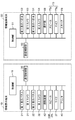
- FIG. 2 is a block diagram illustrating in detail an example of an internal configuration of the information display terminal and the information providing terminal according to the first embodiment.
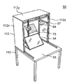
- FIG. 3 is a perspective view showing an example of the appearance of the information providing terminal.
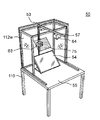
- FIG. 4 is a perspective view showing an internal arrangement example of the information providing terminal with the top plate and one side plate removed.
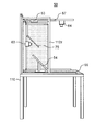
- FIG. 5 is a side view of the inside of the information providing terminal with the top plate and one side plate removed.
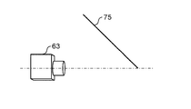
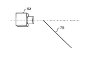
- FIG. 6A is a diagram illustrating a positional relationship between the half mirror and the third camera.
- FIG. 6B is a diagram illustrating a positional relationship between the half mirror and the third camera.
- FIG. 6C is a diagram illustrating a positional relationship between the half mirror and the third camera.
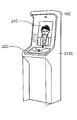
- FIG. 7A is an external view in the front direction of the information display terminal in the first modification.
- FIG. 7B is an external view in the side surface direction of the information display terminal in the first modification.
- FIG. 8A is a perspective view illustrating an appearance of an information display terminal according to the second modification.
- FIG. 8B is a side view of the information display terminal according to the second modification.
- FIG. 9A is a perspective view showing an appearance of a normal-size information display terminal in Modification 3.
- FIG. 9B is an external view in the front direction of a low-size information display terminal in Modification 3.
- FIG. 9A is a perspective view showing an appearance of a normal-size information display terminal in Modification 3.
- FIG. 9B is an external view in the front direction of a low-size information display terminal in Modification 3.
- FIG. 10 is a block diagram illustrating in detail an example of the internal configuration of the information display terminal and the information providing terminal according to the second embodiment.
- FIG. 11 is a diagram illustrating an example of the switching menu displayed on the fourth display panel.
- FIG. 12A is a diagram illustrating a display screen example of the third display panel in each use case.
- FIG. 12B is a diagram illustrating a display screen example of the third display panel in each use case.
- FIG. 12C is a diagram illustrating a display screen example of the third display panel in each use case.
- FIG. 13A is a diagram illustrating a display screen example of the fourth display panel in each use case.
- FIG. 13B is a diagram illustrating a display screen example of the fourth display panel in each use case.
- FIG. 13C is a diagram illustrating a display screen example of the fourth display panel in each use case.
- a user who is a customer who has entered the facility communicates with an operator who is standing by at an operation center that is far away, and receives various guidance from the operator. Applies to possible systems.
- FIG. 1 is a diagram illustrating an example of a schematic configuration of an information display system 5 according to the first embodiment.
- the information display system 5 includes a user-side information display terminal 10 and an operator-side information providing terminal 50 that are connected via a network 90.
- the information display terminal 10 and the information providing terminal 50 can communicate various data (text data, image data, audio data, etc.) with each other via the network 90.
- a wired LAN Local Area Network
- a wide area communication network such as the Internet, a wireless LAN, a dedicated line, or the like
- both the information display terminal 10 and the information providing terminal 50 can access various server devices (not shown) connected to the network 90.
- the information display terminal 10 is placed on a box-shaped mount 12 having a certain height so as to match the height of the person.
- the gantry 12 is integrated with the information display terminal 10 by, for example, being painted in the same color as the casing of the information display terminal 10 or being covered with a cover common to the information display terminal 10.
- the information display terminal 10 includes a first housing 15 provided so as to protrude upward so as to face the user's face, and a part of the user's hand (that is, a hand, an arm, a palm, a nail, or the like). And a second housing 18 extended to the front so that the surrounding area of the hand can be contacted.
- a first display panel 21 on which an image of an operator's face and at least a part of the upper body captured by a third camera 63 described later is displayed.
- an image of at least a part of the operator's face and upper body is displayed with substantially the same size as the actual size.
- a second camera 32 that captures the vicinity of the user's hand is provided at the upper front of the first housing 15.
- a lower portion of the front surface of the first housing 15, that is, an intermediate portion 15 z of the housing in which the first display panel 21 and the second display panel 22 are disposed is an area in which the display panel is not disposed.
- the intermediate portion 15z is provided with a first camera 31 that captures images of at least a part of the user's face and upper body. Near the both ends of the intermediate portion 15z, a pair of left and right speakers 25L and 25R (an example of an output device) that outputs voice data emitted by an operator are provided. Near the center of the intermediate portion 15z, a microphone 27 (an example of an input device) that collects the voice uttered by the user is provided.
- the output device and the input device are arranged in the middle portion 15z of the casing in which the first display panel 21 and the second display panel 22 are arranged, so that the operator is naturally projected on the first display panel 21. Realism is expected to increase.
- a second display panel 22 on which an image near the operator's hand, a UI (User Interface) screen, and the like imaged by a fourth camera 64 described later is displayed.
- the second display panel 22 may be configured with a display device that simply displays an image, or may be configured with a touch panel capable of touch input operation.
- the touch-input information is transmitted from the information display terminal 10 to the information providing terminal 50 connected to the network 90 and various server devices.
- the case where the 2nd display panel 22 is comprised with a touch panel is shown.
- a discharge port of the printer 40 capable of printing a hard copy of the screen displayed on the second display panel 22 is disposed on the front end face 18z of the second casing 18.
- the main body of the printer 40 is built in the gantry 12.
- the front end face 18z of the second housing 18 has authentication information for performing personal authentication of the user (for example, various information about the card required at the time of card settlement processing, and a personal identification number such as a PIN (Personal Identification Number)). ) Is installed.
- the information providing terminal 50 has an operation desk 110. Details of the structure of the information providing terminal 50 including the operation desk 110 will be described later with reference to FIGS. 3 to 5 and will be briefly described here.
- the side plate 112x (see FIG. 3) is removed for the sake of explanation, and the inside can be seen.
- the operator op wearing the headset 73 is sitting on the chair 71 in an easy-to-guide posture.
- the headset 73 is connected to the information providing terminal 50, outputs a voice uttered by the user, and collects a voice uttered by the operator.
- a U-shaped or gate-shaped support base 112 is fixed to the operation surface of the operation desk 110.
- the support base 112 supports electronic components to be described later.
- the support base 112 captures at least a part of the face and upper body of the operator op, and a third display panel 53 on which at least part of the face and upper part of the user imaged by the first camera 31 is projected.
- a third camera 63 is supported.
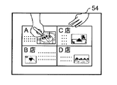
- a fourth display panel 54 that displays an image of the user's hand imaged by the second camera 32 is disposed so as to be easily visible to the operator.
- the screen size of the fourth display panel 54 is larger than that of the third display panel 53, so that the operator op can easily see the user's hand.
- the fourth display panel 54 may be configured by a display device that simply displays an image, or may be configured by a touch panel capable of touch input operation.
- the fourth display panel 54 is configured by a touch panel, the touch-input information is transmitted from the information providing terminal 50 to the information display terminal 10 connected to the network 90 and various server devices.
- the 4th display panel 54 is comprised with a touch panel is shown.
- a fourth camera 64 that images the operation surface of the operation desk 110 including the hand of the operator op is provided.
- the fourth camera 64 can image materials such as a guide pamphlet placed on the operation desk 110 in addition to imaging the hand of the operator op.
- the information providing terminal 50 can capture a Web site, a UI screen, or the like displayed on the fourth display panel 54 as an image captured by the fourth camera 64.
- an operation unit 68 such as a keyboard and a mouse, a scanner 69, and the like can be placed.
- the information display terminal 10 on the user side displays the video of at least a part of the face and upper body of the operator op on the first display panel 21 based on the image data received from the information providing terminal 50, and the second The display panel 22 displays an image of the operator op, a UI screen, and the like. Note that when the operator op places a material such as a guide pamphlet on the surface of the desk 55, the second display panel 22 also displays the material. Further, the information display terminal 10 outputs the audio data received from the information providing terminal 50 from the speakers 25L and 25R, and transmits the audio data collected by the microphone 27 to the information providing terminal 50.
- the information providing terminal 50 on the operator side displays at least a part of the image of the user's face and upper body on the third display panel 53, and the fourth display panel 54.
- the image of the user's hand is displayed on the screen.
- the information providing terminal 50 outputs the audio data received from the information display terminal 10 from the speaker 73z of the headset 73, and transmits the audio data collected by the microphone 73y of the headset 73 to the information display terminal 10.
- the displayable area of the third display panel 53 may be smaller than the displayable area of the fourth display panel 54 that displays the image at hand of the user. This is due to the following reason. What is important for the operator is that the operator op indicates the location indicated by the user with respect to the second display panel 22 that displays information (for example, a brochure, a map, etc.) at hand of the operator op imaged by the fourth camera 64 to the user. Is sharing with the same size as the user. The displayable area of the fourth display panel 54 that displays the image at hand of the user needs a certain size. Furthermore, it is desirable that the resolution and the number of pixels of the fourth display panel 54 are approximately the same as those of the second display panel 22 on the user side.
- the fourth display panel 54 may be a general-purpose monitor.
- the third display panel 53 that displays the user's face (or at least a part of the upper body) only needs to be sufficient for the operator op to understand the user's facial expression and the background situation.
- the displayable area does not have to be so large, and the resolution and the number of pixels do not need to be so high.
- the displayable area of the third display panel 53 may be smaller than the displayable area of the fourth display panel 54 that displays the image at hand of the user, and the resolution and the number of pixels of the third display panel 53 are as follows.
- the resolution and the number of pixels of the fourth display panel 54 may be smaller.
- the third display panel 53 may also be a general-purpose monitor.
- the system of the information providing terminal 50 on the operator op side can be configured using a general-purpose monitor and an information processing apparatus (PC (personal computer), tablet terminal, etc.) or a receiver. That is, the information providing terminal 50 on the operator op side has a simpler configuration than the information display terminal 10 on the user side, but can realize natural and smooth communication between the user and the operator op.
- the layout of each monitor and device has a degree of freedom, so that each monitor and device can always be placed at an optimal position for different operators. .
- FIG. 2 is a block diagram illustrating in detail an example of the internal configuration of the information display terminal 10 and the information providing terminal 50 according to the first embodiment.
- the information display terminal 10 includes a control unit 11 that comprehensively controls each unit.
- the control unit 11 includes communication.
- the control unit 20 is connected.
- the first display panel 21 has an ultra-high resolution 4K display (that is, 3840 pixels ⁇ 2160 pixels) that displays the face of the operator op and a part of the upper body.
- the 1st display panel 21 may be comprised with the touchscreen which a user can touch-input.
- the first camera 31 is a built-in camera disposed in the lower part of the first housing 15 and captures an image of at least a part of the face and upper body of the user standing in front of the information display terminal 10. Note that the angle of view of the first camera 31 may be remotely operable from the information providing terminal 50 on the operator side. As the first camera 31, a high-resolution full high-definition camera, high-definition camera, or normal camera is used.
- the second display panel 22 is configured as a touch panel having a 4K display as an interactive display panel, displays an image of an operator op, an operation menu screen, an application screen, a website, various documents, etc., and is a button by a touch operation. Accepts pressing, handwriting input, and the like.
- the second display panel 22 accepts an input operation with a user's finger or stylus pen for an instruction to enlarge or reduce the screen display.
- the second camera 32 is a built-in camera disposed at the top of the first housing 15, and has a field angle fixed around the second display panel 22, and a video of a user operating the second display panel 22 at hand. And so on.
- the second camera 32 is preferably a 4K or full high vision high resolution camera.
- the 2nd camera 32 is a PTZ camera, it can image so that it can visually recognize to a detail by zooming in on a desired location.
- Speakers 25L and 25R are stereo speakers having directivity that makes it easy for the user in front of the information display terminal 10 to hear, and outputs sound or the like emitted by the operator op.
- the microphone 27 is a directional microphone having a directivity direction with respect to the user, and collects sound emitted by the user. Note that the microphone 27 and the speakers 25L and 25R may be configured as a headset, and when the user operates the information display terminal 10, the headset is attached to the head.
- the printer 40 can print the screen of the second display panel 22 as a hard copy, and prints by either monochrome printing or color printing.
- a printing method an ink jet method, a laser printing method, an electrostatic recording method, or the like is employed.
- the communication control unit 20 as an example of the first communication unit is a network I / F that performs secure communication with the communication control unit 60 of the information providing terminal 50 via the network 90. Specifically, the communication control unit 20 transmits data of the user's face image captured by the first camera 31 and the user's hand image captured by the second camera 32 to the information providing terminal 50. Further, the communication control unit 20 receives the image of the operator's face and at least a part of the upper body and the image of the operator's hand transmitted from the information providing terminal 50.
- the reading device 42 reads the user's personal information.
- a non-contact reader / writer device that reads information on an IC tag by near-field non-contact communication such as NFC (Near Field Communication), or an IC card reader / writer device that reads information on an IC card inserted into a slot.
- NFC Near Field Communication
- a biometric authentication device that performs personal authentication using a pattern such as a fingerprint or a vein may be used.
- the personal information of the user read by the reading device 42 may be used as payment information or electronic money as authentication information. By performing personal authentication, convenience can be improved and spoofing can be eliminated.
- the information display terminal 10 is a multilingual terminal, and when a user selects a language displayed on the second display panel 22 in advance, a voice uttered by the operator op is automatically translated into the selected language. And output from the speakers 25L and 25R.
- the information display terminal 10 also has a function of displaying voices uttered by an operator as text, an OCR function for recognizing handwritten characters, and the like.
- the information providing terminal 50 includes a control unit 51 that controls each unit in an integrated manner.
- the control unit 51 includes communication.
- a control unit 60 is connected.
- the third display panel 53 has a display for displaying at least part of the image of the user's face and upper body.
- the third display panel 53 is not limited to 4K, and may be a normal, high-definition or full high-definition display. Note that the third display panel 53 may be configured with a touch panel that allows an operator op to perform touch input.
- the third camera 63 is a camera attached to the frame 112Z, and images at least a part of the face and upper body of the operator op displayed on the first display panel 21 of the information display terminal 10. It is desirable that the resolution is a 4K camera.
- the fourth display panel 54 is composed of a touch panel having a 4K display as an interactive display panel.
- the fourth display panel 54 displays a user's image, an operation menu screen, an application screen, a website, various documents, and the like, and a button is pressed by a touch operation. Etc. are accepted. Further, the fourth display panel 54 receives an input operation with an operator op's finger or stylus pen for an instruction to enlarge or reduce the screen display.
- the fourth camera 64 is a camera attached to the bar 57, and picks up images, pamphlets, and the like at hand of the operator op placed on the surface of the desk 55.
- the fourth camera 64 captures an image of a hand or the like displayed on the second display panel 22, and is preferably a 4K camera with an ultra-high resolution. Furthermore, in the case of a PTZ camera, details can be imaged so as to be visible.
- the operation unit 68 is an input device such as a mouse or a keyboard that can be operated by the operator op.
- the scanner 69 scans a pamphlet or the like.
- the headset 73 is attached to the head of the operator op, and has a microphone 73y that collects a sound emitted by the operator op, and a pair of left and right speakers 73z that outputs a sound emitted by the user.
- the pair of left and right speakers and microphones may each have a stand-alone casing, in addition to being integrated as a headset.
- the communication control unit 60 as an example of the second communication unit is a network I / F that performs secure communication with the communication control unit 20 of the information display terminal 10 via the network 90. Specifically, the communication control unit 60 stores data of the video of the operator's face and at least a part of the upper body captured by the third camera 63 and the video of the operator's hand captured by the fourth camera 64. It transmits to the display terminal 10. Further, the communication control unit 60 receives the image of the user's face and the image of the user's hand transmitted from the information display terminal 10.
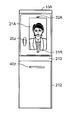
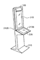
- FIG. 3 is a perspective view showing an example of the appearance of the information providing terminal 50.
- FIG. 4 is a perspective view showing an example of the arrangement inside the information providing terminal 50 with the top plate 112y and one side plate 112x removed.
- FIG. 5 is a side view of the inside of the information providing terminal 50 with the top plate 112y and one side plate 112x removed.
- the information providing terminal 50 includes the operation desk 110 as a main component, and the operation desk 110 includes the third display panel 53, the fourth display panel 54, the half mirror 75, the third camera 63, and the third display panel. It has a configuration in which four cameras 64 are arranged.
- a gate-shaped support base 112 is fixed to the operation surface of the operation desk 110.
- the support base 112 has a structure in which a top plate 112y, two side plates 112x, and a back plate 112w are attached to a frame 112z assembled in a substantially box shape.
- the surface of the support 112 facing the operator is open. 4 and 5, in order to make the inside of the support base 112 easy to understand, one side plate 112x and the top plate 112y are removed for convenience.
- the fourth display panel 54 is attached to the rear side (opposite to the operator), for example, with an inclination of 45 °, so that the operator can easily see.
- a switching menu 122 capable of switching display contents displayed on the fourth display panel 54 is displayed.
- the fourth display panel 54 is configured by a touch panel, and the user may operate the switching menu 122 by directly touching the fourth display panel 54 or may operate the switching menu 122 using a mouse. Also good.
- a third camera 63 capable of imaging the operator is fixed to the frame 112z on the back plate side of the support base 112.
- the third display panel 53 is fixed to the frame 112z on the top plate side of the support base 112.
- a half mirror 75 is attached to the center of the support base 112 so as to be supported by a frame 112z protruding obliquely.
- the half mirror 75 as the reflecting means reflects the light from the image projected on the third display panel 53 to the operator side, and transmits the incident light to the third camera 63 from the operator side at a predetermined angle. (In this embodiment, it is attached with an inclination of 45 ° with respect to the operation surface, for example).
- the half mirror 75, the third display panel 53, and the third camera 63 constitute a function as a prompter system.
- a prompter has a transparent glass plate arranged at a predetermined angle with respect to an operator, for example, information such as characters displayed on a display (monitor, PC, etc.) placed below.
- a transparent glass plate By projecting on a transparent glass plate, and this transparent glass plate reflects information such as characters to the operator side, the operator can visually recognize the information such as characters.
- the half mirror 75 is made of a transparent glass plate.
- the two side plates 112x, the top plate 112y, and the back plate 112w of the support base 112 function as a hood (cover) that blocks outside light incident on the half mirror 75. That is, the fourth display panel 54, the third display panel 53, and the half mirror 75 are covered except for the front surface by the top plate 112y, the two side plates 112x, and the back plate 112w, and thus can block outside light. Thereby, the visibility of the image
- the fourth display panel 54, the center of the fourth display panel 54, the center of the half mirror 75, and the center of the third display panel 53 are positioned on substantially the same vertical line.
- a half mirror 75 and a third display panel 53 are arranged. Since the center of the half mirror 75 and the center of the third display panel 53 are located on substantially the same vertical line, the half mirror 75 can be used in the third display panel 53 without increasing the size of the half mirror 75 more than necessary.
- the video displayed on the screen can be directed to the operator without missing.
- the fourth camera 64 is attached to the bar 57 extending to the operator side as a part of the frame 112z arranged on the upper part of the support base 112 so that the operator's hand can be easily captured.
- the information providing terminal 50 has a reverse arrangement structure, which is different from the prompter system arrangement, in which the third display panel 53 is arranged above the half mirror 75 and the third camera 63 is arranged behind the half mirror 75. .
- the half mirror 75 is arranged between the third display panel 53 and the fourth display panel 54.
- a monitor corresponding to the third display panel is usually arranged below the half mirror.
- the information providing terminal 50 has a normal arrangement structure in which the third display panel 53 is attached to the back side of the fourth display panel 54 as well as the normal prompter. May be.
- the half mirror 75 is arranged above the third display panel 53 and the fourth display panel 54.
- the inclination angle of the half mirror 75 in the normal arrangement is opposite to the inclination angle of the half mirror 75 in the reverse arrangement with respect to the horizontal direction, and is an angle such that the reflection surface floats with respect to the operator side.
- the third display panel 53 is arranged in the back of the fourth display panel 54, so that the length of the support base 112 in the depth direction becomes long. For this reason, a support stand becomes large and it becomes difficult to make compact. In addition, a wasteful space that is not used is also created in the upper part inside the support base.
- the upper portion inside the support base 112 to which the third display panel 53 is attached can be effectively used without leaving a useless space. Accordingly, the length of the support base 112 in the depth direction can be shortened, and the support base 112 can be made compact.
- the third display panel is configured such that the direction of the image displayed on the third display panel 53 in the reverse arrangement is opposite to the direction of the image displayed on the third display panel 53 in the normal arrangement.
- the direction of the image projected on the operator side can be made uniform.
- FIG. 6A, 6B, and 6C are diagrams showing the positional relationship between the half mirror 75 and the third camera 63.
- FIG. 6A, 6B, and 6C are diagrams showing the positional relationship between the half mirror 75 and the third camera 63.
- the half mirror 75 and the third camera 63 are attached so that the optical axis of the third camera 63 is positioned at the lower end of the half mirror 75.
- the third camera 63 captures the operator's face image so that the operator's eyes are slightly upward. As a result, the user can interact with an operator who is displayed on the first display panel 21 and looks slightly up.
- the half mirror 75 and the third camera 63 are attached so that the optical axis of the third camera 63 is positioned at the center of the half mirror 75.
- the third camera 63 captures the operator's face image so that the operator's line of sight is in front. Thereby, the user can interact with the operator of the expression that is displayed on the first display panel 21 and that looks directly in front.
- the half mirror 75 and the third camera 63 are attached so that the optical axis of the third camera 63 is positioned at the upper end of the half mirror 75.
- the third camera 63 captures the operator's face image so that the operator's eyes are slightly downward.
- the user can interact with an operator who is displayed on the first display panel 21 and has a slightly looking down expression.
- the operator has a conversation with the user while viewing the user's face image displayed on the half mirror 75.
- the third camera 63 disposed on the back of the half mirror 75 captures the operator's face image from the front through the half mirror 75.
- the face image of the operator facing the front is displayed on the first display panel 21 of the information display terminal 10.
- the operator slightly shifts his / her line of sight to the fourth display panel 54 located below the half mirror 75 and looks at the image of the user's hand displayed on the fourth display panel 54 while viewing the fourth display panel 54. Operate with touch panel or mouse.
- the fourth camera 64 captures the vicinity of the operator's hand.
- the second display panel 22 of the information display terminal 10 displays an image near the operator's hand that is captured by the fourth camera 64.
- the user can view an image near the operator's hand displayed on the second display panel 22 while watching the operator appearing slightly on the first display panel 21 while the operator is slightly looking down.
- the user receives an impression as if the operator is operating in front of him / her, so that he / she can respond with a sense of reality.
- FIG. 7A and 7B are diagrams illustrating an appearance of the information display terminal 10A according to the first modification.
- FIG. 7A is an external view in the front direction of the information display terminal 10A according to the first modification.
- FIG. 7B is an external view of the information display terminal 10 ⁇ / b> A in the first modification in the side surface direction.
- the information display terminal 10 ⁇ / b> A is a smart integrated case that is shorter and narrower in width than the information display terminal 10 in the above-described embodiment, and has a height similar to a human height (life size).
- a monitor base 213 is provided in the center of the front surface of the housing 212 so as to extend from the housing 212 to the front side.
- the first display panel 21A is disposed on the front surface of the upper portion of the housing 212 (the portion above the monitor base 213 in the figure). On the first display panel 21A, an operator's face image captured by the third camera 63 is displayed.
- an interphone 25z is arranged beside the first display panel 21A instead of the speaker and the microphone.
- a second camera 32A that captures the user's hand and a first camera 31A that captures the user's face image are arranged above and below the first display panel 21A, respectively. It is.
- a hood 214 is provided below the monitor base 213 so as to extend from both sides of the housing 212.
- a printer slot 40z through which printed paper is discharged is provided below the monitor table 213.
- the user can easily store baggage or the like in a space below the monitor base 213 and surrounded by the hood 214.
- the information display terminal 10A in the first modification has a life-size size, the user can face the operator's face image displayed on the first display panel 21A while standing. Therefore, the user can communicate with the operator from a more natural viewpoint.
- the space provided below the monitor base 213 can be used as a simple storage where temporary baggage can be placed, improving convenience.
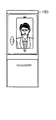
- Modification 2 8A and 8B are diagrams illustrating an appearance of the information display terminal 10B according to the second modification.
- FIG. 8A is a perspective view illustrating an appearance of an information display terminal 10B according to the second modification.
- FIG. 8B is a diagram of the information display terminal 10 ⁇ / b> B according to the second modification viewed from the side.
- the information display terminal 10B has a slim casing 212B with a shorter depth than the information display terminal 10A in the first modification.
- a mountain-shaped base member 215 that supports the casing 212B so as not to fall down is provided at the lower end of the casing 212B.
- the housing 212B is inclined at a predetermined angle so as to lean toward the rear side with respect to the vertical direction.
- the display surface of the first display panel 21B faces slightly upward and more faces the operator's face, thereby improving the visibility of the user.
- the operation surface of the monitor base 213B is inclined downward by a predetermined angle (for example, 15 °) with respect to the horizontal direction.
- a predetermined angle for example, 15 °
- FIG. 9A and 9B are perspective views showing the appearance of information display terminals 10C and 10D having different sizes in Modification 3.
- FIG. 9A is a perspective view illustrating an appearance of an information display terminal 10C having a normal size according to the third modification.
- the information display terminal 10C has substantially the same size as the information display terminal 10A in the first modification, and unlike the information display terminal 10A, the monitor base 213C is inclined toward the front side by a predetermined angle. Therefore, the user can easily operate the operation surface of the second display panel 22C while standing and interacting while looking at the operator's face displayed on the first display panel 21C.
- FIG. 9B is an external view in the front direction of the low-size information display terminal 10D in the third modification.
- the information display terminal 10D is lower in height than the information display terminal 10D of a normal size, and the operator's line of sight is easy for a child or a user on a wheelchair. Therefore, the usability of children and users on wheelchairs is improved.
- the information display system 5 of the present embodiment is an information display system in which the information display terminal 10 that can be operated by the user and the information providing terminal 50 that can be operated by the operator are connected to be communicable.
- the information display terminal 10 includes information on the first camera 31 that captures the image of the user's face, the second camera 32 that captures the image of the user's hand, and data of the image of the user's face and the image of the user's hand.
- a communication control unit 20 (first communication unit) that receives the image of the operator's face and at least a part of the upper body and the image of the operator's hand transmitted to the providing terminal 50 and transmitted from the information providing terminal 50;
- a first display panel 21 that displays an image of the operator's face and at least a part of the upper body, and a second display panel 22 that displays an image of the operator's hand are provided.
- the information providing terminal 50 includes a third camera 63 that images the operator's face and at least a part of the upper body, a fourth camera 64 that images the operator's hand, and images of the operator's face and at least a part of the upper body.
- a communication control unit 60 (second communication unit) that transmits data with the image of the operator's hand to the information display terminal 10 and receives the image of the user's face and the image of the user's hand transmitted from the information display terminal 10. ), A third display panel 53 that displays the video of the user's face, and a fourth display panel 54 that displays the video of the user's hand. Above the fourth display panel 54, a half mirror 75 (reflecting means) that reflects the display content of the third display panel 53 toward the operator and transmits the incident light of the third camera 63 is oblique to the horizontal direction. It is attached at 45 ° (predetermined angle). A third camera 63 is disposed behind the half mirror 75.
- the operator has a conversation with the user while viewing the face image of the user projected by the third display panel 53 and projected on the half mirror 75.
- the third camera 63 disposed on the back of the half mirror 75 captures the operator's face image from the front through the half mirror 75.
- the face image of the operator facing the front is displayed on the first display panel 21 of the information display terminal 10.
- the information display system 5 can communicate with the user from a natural viewpoint while saving the installation equipment space in the arrangement of the terminal on the operator side.
- the third display panel 53 is disposed above the fourth display panel 54, and the half mirror 75 is disposed between the third display panel 53 and the fourth display panel 54.
- the length of the support base 112 in the depth direction can be shortened, and the support base 112 can be made compact.
- the half mirror 75 is attached so that the optical axis of the third camera 63 passes through the center of the half mirror 75.
- the third camera 63 captures the operator's face image so that the operator's line of sight is in front.
- the user can interact with the operator of the expression that is displayed on the first display panel 21 and that looks directly in front.
- the half mirror 75 is attached so that the optical axis of the third camera 63 passes through the upper end of the half mirror 75.
- the third camera 63 captures the operator's face image so that the operator's eyes are slightly downward.
- the user can interact with an operator who is displayed on the first display panel 21 and has a slightly looking down expression.
- the half mirror 75 is attached so that the optical axis of the third camera 63 passes through the lower end of the half mirror 75.
- the third camera 63 captures the operator's face image so that the operator's eyes are slightly upward.
- the user can interact with an operator who is displayed on the first display panel 21 and looks slightly up.
- the information display system of the second embodiment has almost the same configuration as that of the first embodiment.
- the description is abbreviate
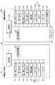
- FIG. 10 is a block diagram showing in detail an example of the internal configuration of the information display terminal 10 and the information providing terminal 50A in the second embodiment.
- the information providing terminal 50A of the second embodiment includes a display switching remote control 85 and a remote control receiving unit 83 that performs wireless connection with the remote control 85.
- control unit 51A in the information providing terminal 50A performs the third operation according to the instruction from the remote control 85 received by the remote control reception unit 83 or the selection of the switching menu 122 (see FIG. 11) displayed on the fourth display panel 54.
- a display switching control unit 51z that switches display contents on the display panel 53 and the fourth display panel 54 is provided.
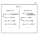
- FIG. 11 is a diagram showing the switching menu 122 displayed on the fourth display panel 54.
- the fourth display panel 54 displays a UI screen that allows touch operation. As part of the UI screen, the fourth display panel 54 displays a third display panel 53 and a switching menu 122 that can switch display contents displayed on the fourth display panel 54.
- a list of display items on the third display panel 53 and the fourth display panel 54 is displayed in a selectable manner.
- As display items of the third display panel 53 No. 1 User face (initial state), No. 2 User's hand, No. 3 Operator's face, No. 4 The operator's hand etc. can be selected.
- As display items on the fourth display panel 54 No. 5 User's hand and UI screen (initial state), No. 6 User's face, No. 7 Operator's face, No. 8 The operator's hand can be selected.
- one of the third display panel 53 and the fourth display panel 54 is fixed to the initial state and the other display item is selected or changed. However, both display items are selected or changed. An operation may be performed.
- the operator can select any display item of the switching menu 122 and switch the display content by directly touching the fourth display panel 54. .
- the operator may select a desired display item by operating the markers 122z and 122y of the switching menu 122 up and down using the remote controller 85.
- the operator may switch to a desired display item by directly specifying, for example, a number without using the switching menu 122.
- the first camera 31 on the information display terminal 10 side photographs the face of the user (customer).
- the second camera 32 on the information display terminal 10 side captures the user's hand.
- the third camera 63 on the information providing terminal 50A side captures the operator's face.
- the fourth camera 64 on the information providing terminal 50A side captures the operator's hand.
- the third display panel 53 on the information providing terminal 50A side is a small monitor, and normally displays the user's face image in the initial state.
- the fourth display panel 54 on the information providing terminal 50A side is a large monitor, and normally displays a user's hand image and a UI (user interface) screen in an initial state.
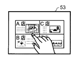
- FIGS 12A, 12B, and 12C are diagrams showing display screens of the third display panel 53 in each use case.
- the third display panel 53 on the information providing terminal 50A side normally displays the face image of the user.
- the third display panel 53 displays a user's hand image captured by the second camera 32 on the information display terminal 10 side.
- the operator operates the UI screen displayed on the fourth display panel 54.
- FIG. 12A a situation as shown in FIG. 12A is assumed.
- a user customer
- brings a paper medium such as a storefront map, a leaflet, or a pamphlet and spreads it to his hand and makes an inquiry to the operator
- the second camera 32 images these paper medium.
- the operator operates the UI screen of the fourth display panel 54 while checking the information on the paper medium displayed on the third display panel 53, and searches for related information such as the presence / absence of inventory and the sales floor, and is appropriate for the user. Make a response.
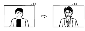
- the third display panel 53 displays an operator's face image (including the upper body) captured by the third camera 63 on the information providing terminal 50A side.
- the operator adjusts the focus, zoom, and the like of the third camera 63 while viewing his / her face image displayed on the third display panel 53.
- the focus of the operator's image captured by the third camera 63 may be slightly shifted depending on the physique of the operator and how to sit down.
- the operator appropriately sets the third camera 63 for the user (customer) while checking on the third display panel 53 how his / her face image is visible. Change to
- the third display panel 53 normally displays the user's face, and the operator is interacting with the user while looking at the third display panel 53. Even if you switch to your own face image, you can check your own image without changing your line of sight. Therefore, the operator can easily confirm the video of the operator actually viewed by the user by adjusting the third camera 63 while looking at the third display panel 53. Thereby, the 3rd camera 63 can be adjusted easily.
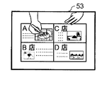
- the third display panel 53 displays the operator's hand image captured by the fourth camera 64, as shown in FIG. 12C.
- the operator adjusts the focus, zoom, and the like of the fourth camera 64 while looking at his / her hand image displayed on the third display panel 53.
- the operator When the information display system 5 is initially set, the operator focuses the fourth camera 64.
- the third display panel 53 displays a map or a flyer as an operator's hand image during dialogue with the user (customer), it is difficult to see the third display panel 53 by enlarging the fourth camera 64 by optical zoom. Maps and flyers become clearer. As a result, the user can check the contents of the map or flyer. Note that the operator may enlarge the fourth camera 64 and then return the settings (coordinates) and the like of the fourth camera 64 to preset values (initial positions) stored in advance.
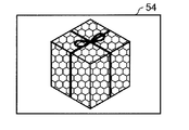
- FIGS. 13A, 13B, and 13C are diagrams showing display screens of the fourth display panel 54 in each use case.
- the fourth display panel 54 normally displays the user's hand image and UI screen.
- the hand image includes a UI screen when there is a UI screen in the vicinity of the hand image.
- the fourth display panel 54 displays the user's hand image. Normally, the third display panel 53 displays the user's face image captured by the first camera 31, but it is difficult to confirm the contents of the range corresponding to the face image in the image captured by the second camera 32. , The fourth display panel 54 corresponds to this.
- the operator correctly displays the content of the product in the user's hand image captured by the second camera 32 installed above the information display terminal 10. It may not be confirmed.
- the operator instructs the first camera 31 installed below the information display terminal 10 by voice or the like so that the user can take an image by moving the product closer or away from the first camera 31, as shown in FIG. 13A.
- the operator can confirm the contents of the commodity imaged by the first camera 31 displayed on the fourth display panel 54.
- the fourth display panel 54 displays an operator's face image (including the upper body) captured by the third camera 63.
- the operator interacts with the user while confirming how his / her face image looks to the user (customer).
- the fourth display panel 54 displays the operator's hand image captured by the fourth camera 64.
- the operator interacts with the user while confirming how the user's hand image looks to the user.
- the operator adjusts the focus and zoom of the fourth camera 64.
- the fourth display panel 54 may display the operator's hand image and the UI screen at the same time.
- the operator's hand image may be displayed as a wipe image such as a small window. Is possible.
- the information display system 5A in the second embodiment is an information display system in which the information display terminal 10 that can be operated by the user and the information providing terminal 50A that can be operated by the operator are communicably connected.
- the information display terminal 10 includes information on the first camera 31 that captures the image of the user's face, the second camera 32 that captures the image of the user's hand, and data of the image of the user's face and the image of the user's hand.
- a communication control unit 20 (first communication unit) that receives the image of the operator's face and at least a part of the upper body and the image of the operator's hand transmitted to the providing terminal 50A and transmitted from the information providing terminal 50A;
- a first display panel 21 that displays an image of the operator's face and at least a part of the upper body, and a second display panel 22 that displays an image of the operator's hand are provided.
- the information providing terminal 50A includes a third camera 63 that images the operator's face and at least a part of the upper body, a fourth camera 64 that images the operator's hand, and images of the operator's face and at least a part of the upper body.
- a communication control unit 60 (second communication unit) that transmits data with the image of the operator's hand to the information display terminal 10 and receives the image of the user's face and the image of the user's hand transmitted from the information display terminal 10. ), A third display panel 53 that displays the video of the user's face, and a fourth display panel 54 that displays the video of the user's hand.
- the display switching control unit 51z switching processing unit displays the display content of the third display panel 53 from the video of the user's face captured by the first camera 31, the second camera 32, the third camera 63, and the fourth camera. 64, an instruction to switch to an image captured by any one of the cameras is given.
- the display content of the third display panel is displayed as the image of the face of the user. To other captured images. Therefore, it is possible to provide the user with a sense of reality that the user is actually facing the communication partner, thereby improving the usability of the operator.
- the display switching control unit 51z changes the display content of the fourth display panel 54 from the first camera 31, the third camera 63, and the fourth camera 64 from the image of the user's hand imaged by the second camera 32. An instruction to switch to an image captured by any camera is given. Thereby, the display content of the fourth display panel can be switched from the user's hand image to another captured image, and the convenience of the operator can be improved.
- the information display system 5 includes a remote controller 85 for switching the display.
- the display switching control unit 51z instructs switching by operating the remote controller 85. In this way, the switching instruction can be easily performed by using the remote controller. Further, it is possible to instruct switching of the display contents even in a place where the person who owns the remote control is away from the information providing terminal. Furthermore, even if the operator does not know the switching of the display contents, it is possible to instruct switching of the display contents instead.
- the fourth display panel 54 displays a switching menu 122.
- the display switching control unit 51z instructs switching by an operation on the switching menu 122. As a result, the operator can easily instruct switching while looking at the fourth display panel.
- the information display system has shown a case where the information display terminal and the information providing terminal communicate on a one-to-one basis.
- one-to-N, N-to-one, N-to-N N: plural
- the present disclosure can also be applied when communicating via a multipoint connection.
- the first display panel to the fourth display panel display a face image or a hand image captured by each camera in a plurality of terminals in a multi-screen display or a screen switching display. Also good.
- the first display panel to the fourth display panel may be capable of displaying a plurality of terminal information together.
- the display contents of the third display panel 53 and the fourth display panel 54 when the display contents of the third display panel 53 and the fourth display panel 54 are switched, one of the display contents is fixed and the other display contents can be arbitrarily switched.
- the display contents of both the display panel 53 and the fourth display panel 54 may be switched at the same time.
- a combination of these display contents may be registered in advance according to the use case.
- the information providing terminal may be configured such that the operator directly views the fourth display panel without using a prompter system, that is, without using a half mirror.
- the information display terminal projects at least part of the upper body as the most natural feeling when projecting at least part of the operator's face and upper body. You may project up to the elbow or waist area. Further, it is possible to project only up to the vicinity of the neck or the face without projecting almost the upper body. In addition, it is desirable that the face and a part of the upper body projected on the display panel are projected so as to match the actual size, which makes the feeling more natural. Further, when the information display terminal has a life-size display panel, the whole body of the operator may be projected. In this case, the operator may be in the same standing posture as the user or may be in a sitting posture.
- An information display system and an information providing terminal according to the present disclosure are capable of communicating with a natural viewpoint to a user while saving space of installed equipment in the arrangement of terminals on an operator side. It is useful as a providing terminal.
Abstract
Selon l'invention, un terminal de fourniture d'informations comprend un demi-miroir placé au-dessus d'un quatrième panneau d'affichage et reflétant un contenu affiché d'un troisième panneau d'affichage à destination d'un opérateur tout en transmettant une lumière incidente sur une troisième caméra, le demi-miroir étant incliné à 45° par rapport à la direction horizontale. La troisième caméra est placée à l'arrière du demi-miroir. L'opérateur converse avec un utilisateur tout en regardant une image faciale de l'utilisateur projetée par le troisième panneau d'affichage et représentée sur le demi-miroir. La troisième caméra placée derrière le demi-miroir capture une image faciale de l'opérateur depuis l'avant, à travers le demi-miroir. L'image faciale de l'opérateur regardant vers l'avant s'affiche alors sur un premier panneau d'affichage d'un terminal d'affichage d'informations.
Priority Applications (4)
| Application Number | Priority Date | Filing Date | Title |
|---|---|---|---|
| CN201780018960.2A CN108781274A (zh) | 2016-03-25 | 2017-03-09 | 信息显示系统和信息提供终端 |
| EP17769940.2A EP3435662A4 (fr) | 2016-03-25 | 2017-03-09 | Système d'affichage d'informations, et terminal de fourniture d'informations |
| US16/084,448 US10582153B2 (en) | 2016-03-25 | 2017-03-09 | Information displaying system and information providing terminal |
| US16/084,448 US20190075272A1 (en) | 2016-03-25 | 2018-03-09 | Information displaying system and information providing terminal |
Applications Claiming Priority (2)
| Application Number | Priority Date | Filing Date | Title |
|---|---|---|---|
| JP2016062797A JP2017175579A (ja) | 2016-03-25 | 2016-03-25 | 情報表示システム及び情報提供端末 |
| JP2016-062797 | 2016-03-25 |
Publications (1)
| Publication Number | Publication Date |
|---|---|
| WO2017163895A1 true WO2017163895A1 (fr) | 2017-09-28 |
Family
ID=59900181
Family Applications (1)
| Application Number | Title | Priority Date | Filing Date |
|---|---|---|---|
| PCT/JP2017/009410 WO2017163895A1 (fr) | 2016-03-25 | 2017-03-09 | Système d'affichage d'informations, et terminal de fourniture d'informations |
Country Status (5)
| Country | Link |
|---|---|
| US (2) | US10582153B2 (fr) |
| EP (1) | EP3435662A4 (fr) |
| JP (1) | JP2017175579A (fr) |
| CN (1) | CN108781274A (fr) |
| WO (1) | WO2017163895A1 (fr) |
Families Citing this family (5)
| Publication number | Priority date | Publication date | Assignee | Title |
|---|---|---|---|---|
| US11290628B2 (en) * | 2018-12-27 | 2022-03-29 | Dynascan Technology Corp. | Display apparatus |
| USD907032S1 (en) | 2019-07-07 | 2021-01-05 | Tangible Play, Inc. | Virtualization device |
| US20210006730A1 (en) | 2019-07-07 | 2021-01-07 | Tangible Play, Inc. | Computing device |
| US11522961B2 (en) | 2019-10-23 | 2022-12-06 | Ricoh Company, Ltd. | Communication terminal, communication system, communication method, and non-transitory computer-readable medium |
| US20220368853A1 (en) * | 2021-05-13 | 2022-11-17 | Graham Smith | Multimodal Video Conferencing Device |
Citations (3)
| Publication number | Priority date | Publication date | Assignee | Title |
|---|---|---|---|---|
| JPH0224687U (fr) * | 1988-07-29 | 1990-02-19 | ||
| JP2004056207A (ja) * | 2002-07-16 | 2004-02-19 | Oki Electric Ind Co Ltd | コミュニケーション装置およびそのプログラム |
| JP2010504709A (ja) * | 2006-09-22 | 2010-02-12 | ピーター マクダフィー ホワイト | 3次元ディスプレイおよびテレプレゼンシステムならびにその方法 |
Family Cites Families (5)
| Publication number | Priority date | Publication date | Assignee | Title |
|---|---|---|---|---|
| JPH0224687A (ja) | 1988-07-13 | 1990-01-26 | Hitachi Ltd | 定着装置 |
| US5239373A (en) * | 1990-12-26 | 1993-08-24 | Xerox Corporation | Video computational shared drawing space |
| US8199185B2 (en) * | 1995-09-20 | 2012-06-12 | Videotronic Systems | Reflected camera image eye contact terminal |
| US5639151A (en) * | 1996-02-16 | 1997-06-17 | Mcnelley; Steve H. | Pass-through reflective projection display |
| JP2004147105A (ja) | 2002-10-24 | 2004-05-20 | Oki Electric Ind Co Ltd | 遠隔対面用端末装置 |
-
2016
- 2016-03-25 JP JP2016062797A patent/JP2017175579A/ja active Pending
-
2017
- 2017-03-09 WO PCT/JP2017/009410 patent/WO2017163895A1/fr active Application Filing
- 2017-03-09 EP EP17769940.2A patent/EP3435662A4/fr not_active Withdrawn
- 2017-03-09 CN CN201780018960.2A patent/CN108781274A/zh active Pending
- 2017-03-09 US US16/084,448 patent/US10582153B2/en not_active Expired - Fee Related
-
2018
- 2018-03-09 US US16/084,448 patent/US20190075272A1/en active Granted
Patent Citations (3)
| Publication number | Priority date | Publication date | Assignee | Title |
|---|---|---|---|---|
| JPH0224687U (fr) * | 1988-07-29 | 1990-02-19 | ||
| JP2004056207A (ja) * | 2002-07-16 | 2004-02-19 | Oki Electric Ind Co Ltd | コミュニケーション装置およびそのプログラム |
| JP2010504709A (ja) * | 2006-09-22 | 2010-02-12 | ピーター マクダフィー ホワイト | 3次元ディスプレイおよびテレプレゼンシステムならびにその方法 |
Non-Patent Citations (1)
| Title |
|---|
| See also references of EP3435662A4 * |
Also Published As
| Publication number | Publication date |
|---|---|
| US10582153B2 (en) | 2020-03-03 |
| CN108781274A (zh) | 2018-11-09 |
| JP2017175579A (ja) | 2017-09-28 |
| EP3435662A1 (fr) | 2019-01-30 |
| EP3435662A4 (fr) | 2019-03-27 |
| US20190075272A1 (en) | 2019-03-07 |
Similar Documents
| Publication | Publication Date | Title |
|---|---|---|
| WO2017163895A1 (fr) | Système d'affichage d'informations, et terminal de fourniture d'informations | |
| WO2017163897A1 (fr) | Système d'affichage d'informations et terminal de fourniture d'informations | |
| EP3316573B1 (fr) | Système d'affichage d'informations et terminal d'affichage d'informations | |
| US11005982B2 (en) | Information processing terminal | |
| CN111309183B (zh) | 触控显示系统及其控制方法 | |
| JP2014157482A (ja) | 操作表示システム | |
| JPH11127275A (ja) | 通信装置 | |
| JP2010504709A (ja) | 3次元ディスプレイおよびテレプレゼンシステムならびにその方法 | |
| US20080055564A1 (en) | Interactive document camera and system of the same | |
| JP2013054643A (ja) | 情報表示装置およびプログラム | |
| JP2018067261A (ja) | 表示システム | |
| JP2018112894A (ja) | システムおよび制御方法 | |
| JPH10124178A (ja) | 電子メール端末、電子メール端末の処理方法、媒体 | |
| US11161048B2 (en) | Interactive table covering device and electronic interactive table system | |
| CN115004281A (zh) | 视听终端、视听方法、视听系统以及程序 | |
| JP3074677B2 (ja) | 伝送手段を介して対話者間の視線を一致させる機構を備えた双方向対話型システム | |
| JP2003043579A (ja) | 出力機能を備えたオーバーヘッドスライドプロジェクタシステムおよび該システムを含む多機能オフィス機器装置ならびにオーバーヘッドプロジェクタからスライドのコピーを生成する方法 | |
| JPH11289523A (ja) | 双方向対話型システム | |
| JP2970661B2 (ja) | モニタ像の表示方法 | |
| JP2023049060A (ja) | 書画カメラ | |
| WO2019234462A1 (fr) | Système et procédé de fourniture d'une collaboration visuelle, en particulier un service de client virtuel entre des personnes à distance | |
| JP2023067427A (ja) | プレゼンテーション用システム及びプログラム | |
| JP2021026750A (ja) | 受付装置 | |
| JP3074678B2 (ja) | 端末装置 | |
| JP2000134594A (ja) | 書類デ―タ等送信システム |
Legal Events
| Date | Code | Title | Description |
|---|---|---|---|
| NENP | Non-entry into the national phase |
Ref country code: DE |
|
| WWE | Wipo information: entry into national phase |
Ref document number: 2017769940 Country of ref document: EP |
|
| ENP | Entry into the national phase |
Ref document number: 2017769940 Country of ref document: EP Effective date: 20181025 |
|
| 121 | Ep: the epo has been informed by wipo that ep was designated in this application |
Ref document number: 17769940 Country of ref document: EP Kind code of ref document: A1 |