WO2017163895A1 - Information displaying system and information providing terminal - Google Patents
Information displaying system and information providing terminal Download PDFInfo
- Publication number
- WO2017163895A1 WO2017163895A1 PCT/JP2017/009410 JP2017009410W WO2017163895A1 WO 2017163895 A1 WO2017163895 A1 WO 2017163895A1 JP 2017009410 W JP2017009410 W JP 2017009410W WO 2017163895 A1 WO2017163895 A1 WO 2017163895A1
- Authority
- WO
- WIPO (PCT)
- Prior art keywords
- operator
- display panel
- user
- camera
- image
- Prior art date
Links
Images


Classifications
-
- H—ELECTRICITY
- H04—ELECTRIC COMMUNICATION TECHNIQUE
- H04N—PICTORIAL COMMUNICATION, e.g. TELEVISION
- H04N7/00—Television systems
- H04N7/14—Systems for two-way working
- H04N7/141—Systems for two-way working between two video terminals, e.g. videophone
- H04N7/142—Constructional details of the terminal equipment, e.g. arrangements of the camera and the display
-
- H—ELECTRICITY
- H04—ELECTRIC COMMUNICATION TECHNIQUE
- H04N—PICTORIAL COMMUNICATION, e.g. TELEVISION
- H04N23/00—Cameras or camera modules comprising electronic image sensors; Control thereof
- H04N23/90—Arrangement of cameras or camera modules, e.g. multiple cameras in TV studios or sports stadiums
Definitions
- This disclosure relates to an information display system and an information providing terminal that display information.
- the multimedia terminal of Patent Document 1 has a camera and three displays, images the user's face and hand with the camera, and transmits the captured image to the operator's terminal. Also, the multimedia terminal displays the user's face on the first display among the three displays, displays multimedia information such as text, still images, and moving images on the second display, and displays on the third display. Displays a touch panel or input panel that can input characters and symbols. Further, the multimedia terminal has a microphone and a speaker for a call with the operator's terminal.
- an operator side camera on the operator side and an operator side monitor on which an image of the user's face is displayed If they are arranged apart from each other, there are the following problems. That is, when the operator talks to the user while looking at the monitor, the camera captures the operator's face from an angle different from the angle at which the operator looks at the monitor. In this case, a monitor provided on the user side (that is, a monitor on which an image of the operator's face is displayed) is projected as if the operator's face is looking in a direction different from the direction in which the user is looking. Therefore, the user cannot take a natural communication with the operator such as speaking with the line of sight facing the same direction, resulting in an unnatural dialogue.
- This disclosure is intended to communicate with the user from a natural viewpoint while saving the space of the installed equipment in the arrangement of terminals on the operator side.
- An information display system is an information display system in which an information display terminal that can be operated by a user and an information providing terminal that can be operated by an operator are connected to be able to communicate with each other.
- a first camera that captures a face, a second camera that captures the user's hand, a video of the user's face, and a video of the user's hand are transmitted to the information providing terminal and transmitted from the information providing terminal.
- a first communication unit that receives the image of the operator's face and at least a part of the upper body and the image of the operator's hand, and displays an image of the operator's face and at least a part of the upper body.
- a third camera that captures the operator's hand, a video of the operator's face and at least a part of the upper body, and a video of the operator's hand to the information display terminal.
- a second communication unit that receives a video of the user's face and a video of the user's hand transmitted from the display terminal; a third display panel that displays the video of the user's face; A fourth display panel for displaying an image, and reflects the display content of the third display panel toward the operator and transmits the incident light of the third camera above the fourth display panel. Reflecting means is attached at a predetermined angle, and the third camera is arranged behind the reflecting means.
- the information providing terminal is an information providing terminal that is communicably connected to an information display terminal that can be operated by a user and that can be operated by an operator, and is at least part of the face and upper body of the operator.
- a first camera that images the operator's hand, a video of the operator's face and at least a part of the upper body, and an image of the operator's hand are transmitted to the information display terminal.
- a communication unit that receives the video of the user's face and the video of the user's hand transmitted from the information display terminal, a first display panel that displays the video of the user's face, and the hand of the user
- a second display panel that displays the image of the first display panel, the display content of the first display panel being reflected toward the operator above the second display panel, and the third camera Reflecting means for transmitting the incident light is mounted at a predetermined angle, the first camera to the rear of the reflecting means is disposed.
- FIG. 1 is a diagram illustrating an example of a schematic configuration of an information display system according to the first embodiment.
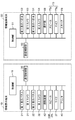
- FIG. 2 is a block diagram illustrating in detail an example of an internal configuration of the information display terminal and the information providing terminal according to the first embodiment.
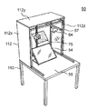
- FIG. 3 is a perspective view showing an example of the appearance of the information providing terminal.
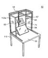
- FIG. 4 is a perspective view showing an internal arrangement example of the information providing terminal with the top plate and one side plate removed.
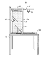
- FIG. 5 is a side view of the inside of the information providing terminal with the top plate and one side plate removed.
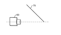
- FIG. 6A is a diagram illustrating a positional relationship between the half mirror and the third camera.
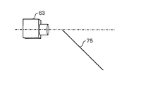
- FIG. 6B is a diagram illustrating a positional relationship between the half mirror and the third camera.
- FIG. 6C is a diagram illustrating a positional relationship between the half mirror and the third camera.
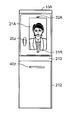
- FIG. 7A is an external view in the front direction of the information display terminal in the first modification.
- FIG. 7B is an external view in the side surface direction of the information display terminal in the first modification.
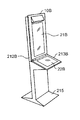
- FIG. 8A is a perspective view illustrating an appearance of an information display terminal according to the second modification.
- FIG. 8B is a side view of the information display terminal according to the second modification.
- FIG. 9A is a perspective view showing an appearance of a normal-size information display terminal in Modification 3.
- FIG. 9B is an external view in the front direction of a low-size information display terminal in Modification 3.
- FIG. 9A is a perspective view showing an appearance of a normal-size information display terminal in Modification 3.
- FIG. 9B is an external view in the front direction of a low-size information display terminal in Modification 3.
- FIG. 10 is a block diagram illustrating in detail an example of the internal configuration of the information display terminal and the information providing terminal according to the second embodiment.
- FIG. 11 is a diagram illustrating an example of the switching menu displayed on the fourth display panel.
- FIG. 12A is a diagram illustrating a display screen example of the third display panel in each use case.
- FIG. 12B is a diagram illustrating a display screen example of the third display panel in each use case.
- FIG. 12C is a diagram illustrating a display screen example of the third display panel in each use case.
- FIG. 13A is a diagram illustrating a display screen example of the fourth display panel in each use case.
- FIG. 13B is a diagram illustrating a display screen example of the fourth display panel in each use case.
- FIG. 13C is a diagram illustrating a display screen example of the fourth display panel in each use case.
- a user who is a customer who has entered the facility communicates with an operator who is standing by at an operation center that is far away, and receives various guidance from the operator. Applies to possible systems.
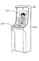
- FIG. 1 is a diagram illustrating an example of a schematic configuration of an information display system 5 according to the first embodiment.
- the information display system 5 includes a user-side information display terminal 10 and an operator-side information providing terminal 50 that are connected via a network 90.
- the information display terminal 10 and the information providing terminal 50 can communicate various data (text data, image data, audio data, etc.) with each other via the network 90.
- a wired LAN Local Area Network
- a wide area communication network such as the Internet, a wireless LAN, a dedicated line, or the like
- both the information display terminal 10 and the information providing terminal 50 can access various server devices (not shown) connected to the network 90.
- the information display terminal 10 is placed on a box-shaped mount 12 having a certain height so as to match the height of the person.
- the gantry 12 is integrated with the information display terminal 10 by, for example, being painted in the same color as the casing of the information display terminal 10 or being covered with a cover common to the information display terminal 10.
- the information display terminal 10 includes a first housing 15 provided so as to protrude upward so as to face the user's face, and a part of the user's hand (that is, a hand, an arm, a palm, a nail, or the like). And a second housing 18 extended to the front so that the surrounding area of the hand can be contacted.
- a first display panel 21 on which an image of an operator's face and at least a part of the upper body captured by a third camera 63 described later is displayed.
- an image of at least a part of the operator's face and upper body is displayed with substantially the same size as the actual size.
- a second camera 32 that captures the vicinity of the user's hand is provided at the upper front of the first housing 15.
- a lower portion of the front surface of the first housing 15, that is, an intermediate portion 15 z of the housing in which the first display panel 21 and the second display panel 22 are disposed is an area in which the display panel is not disposed.
- the intermediate portion 15z is provided with a first camera 31 that captures images of at least a part of the user's face and upper body. Near the both ends of the intermediate portion 15z, a pair of left and right speakers 25L and 25R (an example of an output device) that outputs voice data emitted by an operator are provided. Near the center of the intermediate portion 15z, a microphone 27 (an example of an input device) that collects the voice uttered by the user is provided.
- the output device and the input device are arranged in the middle portion 15z of the casing in which the first display panel 21 and the second display panel 22 are arranged, so that the operator is naturally projected on the first display panel 21. Realism is expected to increase.
- a second display panel 22 on which an image near the operator's hand, a UI (User Interface) screen, and the like imaged by a fourth camera 64 described later is displayed.
- the second display panel 22 may be configured with a display device that simply displays an image, or may be configured with a touch panel capable of touch input operation.
- the touch-input information is transmitted from the information display terminal 10 to the information providing terminal 50 connected to the network 90 and various server devices.
- the case where the 2nd display panel 22 is comprised with a touch panel is shown.
- a discharge port of the printer 40 capable of printing a hard copy of the screen displayed on the second display panel 22 is disposed on the front end face 18z of the second casing 18.
- the main body of the printer 40 is built in the gantry 12.
- the front end face 18z of the second housing 18 has authentication information for performing personal authentication of the user (for example, various information about the card required at the time of card settlement processing, and a personal identification number such as a PIN (Personal Identification Number)). ) Is installed.
- the information providing terminal 50 has an operation desk 110. Details of the structure of the information providing terminal 50 including the operation desk 110 will be described later with reference to FIGS. 3 to 5 and will be briefly described here.
- the side plate 112x (see FIG. 3) is removed for the sake of explanation, and the inside can be seen.
- the operator op wearing the headset 73 is sitting on the chair 71 in an easy-to-guide posture.
- the headset 73 is connected to the information providing terminal 50, outputs a voice uttered by the user, and collects a voice uttered by the operator.
- a U-shaped or gate-shaped support base 112 is fixed to the operation surface of the operation desk 110.
- the support base 112 supports electronic components to be described later.
- the support base 112 captures at least a part of the face and upper body of the operator op, and a third display panel 53 on which at least part of the face and upper part of the user imaged by the first camera 31 is projected.
- a third camera 63 is supported.
- a fourth display panel 54 that displays an image of the user's hand imaged by the second camera 32 is disposed so as to be easily visible to the operator.
- the screen size of the fourth display panel 54 is larger than that of the third display panel 53, so that the operator op can easily see the user's hand.
- the fourth display panel 54 may be configured by a display device that simply displays an image, or may be configured by a touch panel capable of touch input operation.
- the fourth display panel 54 is configured by a touch panel, the touch-input information is transmitted from the information providing terminal 50 to the information display terminal 10 connected to the network 90 and various server devices.
- the 4th display panel 54 is comprised with a touch panel is shown.
- a fourth camera 64 that images the operation surface of the operation desk 110 including the hand of the operator op is provided.
- the fourth camera 64 can image materials such as a guide pamphlet placed on the operation desk 110 in addition to imaging the hand of the operator op.
- the information providing terminal 50 can capture a Web site, a UI screen, or the like displayed on the fourth display panel 54 as an image captured by the fourth camera 64.
- an operation unit 68 such as a keyboard and a mouse, a scanner 69, and the like can be placed.
- the information display terminal 10 on the user side displays the video of at least a part of the face and upper body of the operator op on the first display panel 21 based on the image data received from the information providing terminal 50, and the second The display panel 22 displays an image of the operator op, a UI screen, and the like. Note that when the operator op places a material such as a guide pamphlet on the surface of the desk 55, the second display panel 22 also displays the material. Further, the information display terminal 10 outputs the audio data received from the information providing terminal 50 from the speakers 25L and 25R, and transmits the audio data collected by the microphone 27 to the information providing terminal 50.
- the information providing terminal 50 on the operator side displays at least a part of the image of the user's face and upper body on the third display panel 53, and the fourth display panel 54.
- the image of the user's hand is displayed on the screen.
- the information providing terminal 50 outputs the audio data received from the information display terminal 10 from the speaker 73z of the headset 73, and transmits the audio data collected by the microphone 73y of the headset 73 to the information display terminal 10.
- the displayable area of the third display panel 53 may be smaller than the displayable area of the fourth display panel 54 that displays the image at hand of the user. This is due to the following reason. What is important for the operator is that the operator op indicates the location indicated by the user with respect to the second display panel 22 that displays information (for example, a brochure, a map, etc.) at hand of the operator op imaged by the fourth camera 64 to the user. Is sharing with the same size as the user. The displayable area of the fourth display panel 54 that displays the image at hand of the user needs a certain size. Furthermore, it is desirable that the resolution and the number of pixels of the fourth display panel 54 are approximately the same as those of the second display panel 22 on the user side.
- the fourth display panel 54 may be a general-purpose monitor.
- the third display panel 53 that displays the user's face (or at least a part of the upper body) only needs to be sufficient for the operator op to understand the user's facial expression and the background situation.
- the displayable area does not have to be so large, and the resolution and the number of pixels do not need to be so high.
- the displayable area of the third display panel 53 may be smaller than the displayable area of the fourth display panel 54 that displays the image at hand of the user, and the resolution and the number of pixels of the third display panel 53 are as follows.
- the resolution and the number of pixels of the fourth display panel 54 may be smaller.
- the third display panel 53 may also be a general-purpose monitor.
- the system of the information providing terminal 50 on the operator op side can be configured using a general-purpose monitor and an information processing apparatus (PC (personal computer), tablet terminal, etc.) or a receiver. That is, the information providing terminal 50 on the operator op side has a simpler configuration than the information display terminal 10 on the user side, but can realize natural and smooth communication between the user and the operator op.
- the layout of each monitor and device has a degree of freedom, so that each monitor and device can always be placed at an optimal position for different operators. .
- FIG. 2 is a block diagram illustrating in detail an example of the internal configuration of the information display terminal 10 and the information providing terminal 50 according to the first embodiment.
- the information display terminal 10 includes a control unit 11 that comprehensively controls each unit.
- the control unit 11 includes communication.
- the control unit 20 is connected.
- the first display panel 21 has an ultra-high resolution 4K display (that is, 3840 pixels ⁇ 2160 pixels) that displays the face of the operator op and a part of the upper body.
- the 1st display panel 21 may be comprised with the touchscreen which a user can touch-input.
- the first camera 31 is a built-in camera disposed in the lower part of the first housing 15 and captures an image of at least a part of the face and upper body of the user standing in front of the information display terminal 10. Note that the angle of view of the first camera 31 may be remotely operable from the information providing terminal 50 on the operator side. As the first camera 31, a high-resolution full high-definition camera, high-definition camera, or normal camera is used.
- the second display panel 22 is configured as a touch panel having a 4K display as an interactive display panel, displays an image of an operator op, an operation menu screen, an application screen, a website, various documents, etc., and is a button by a touch operation. Accepts pressing, handwriting input, and the like.
- the second display panel 22 accepts an input operation with a user's finger or stylus pen for an instruction to enlarge or reduce the screen display.
- the second camera 32 is a built-in camera disposed at the top of the first housing 15, and has a field angle fixed around the second display panel 22, and a video of a user operating the second display panel 22 at hand. And so on.
- the second camera 32 is preferably a 4K or full high vision high resolution camera.
- the 2nd camera 32 is a PTZ camera, it can image so that it can visually recognize to a detail by zooming in on a desired location.
- Speakers 25L and 25R are stereo speakers having directivity that makes it easy for the user in front of the information display terminal 10 to hear, and outputs sound or the like emitted by the operator op.
- the microphone 27 is a directional microphone having a directivity direction with respect to the user, and collects sound emitted by the user. Note that the microphone 27 and the speakers 25L and 25R may be configured as a headset, and when the user operates the information display terminal 10, the headset is attached to the head.
- the printer 40 can print the screen of the second display panel 22 as a hard copy, and prints by either monochrome printing or color printing.
- a printing method an ink jet method, a laser printing method, an electrostatic recording method, or the like is employed.
- the communication control unit 20 as an example of the first communication unit is a network I / F that performs secure communication with the communication control unit 60 of the information providing terminal 50 via the network 90. Specifically, the communication control unit 20 transmits data of the user's face image captured by the first camera 31 and the user's hand image captured by the second camera 32 to the information providing terminal 50. Further, the communication control unit 20 receives the image of the operator's face and at least a part of the upper body and the image of the operator's hand transmitted from the information providing terminal 50.
- the reading device 42 reads the user's personal information.
- a non-contact reader / writer device that reads information on an IC tag by near-field non-contact communication such as NFC (Near Field Communication), or an IC card reader / writer device that reads information on an IC card inserted into a slot.
- NFC Near Field Communication
- a biometric authentication device that performs personal authentication using a pattern such as a fingerprint or a vein may be used.
- the personal information of the user read by the reading device 42 may be used as payment information or electronic money as authentication information. By performing personal authentication, convenience can be improved and spoofing can be eliminated.
- the information display terminal 10 is a multilingual terminal, and when a user selects a language displayed on the second display panel 22 in advance, a voice uttered by the operator op is automatically translated into the selected language. And output from the speakers 25L and 25R.
- the information display terminal 10 also has a function of displaying voices uttered by an operator as text, an OCR function for recognizing handwritten characters, and the like.
- the information providing terminal 50 includes a control unit 51 that controls each unit in an integrated manner.
- the control unit 51 includes communication.
- a control unit 60 is connected.
- the third display panel 53 has a display for displaying at least part of the image of the user's face and upper body.
- the third display panel 53 is not limited to 4K, and may be a normal, high-definition or full high-definition display. Note that the third display panel 53 may be configured with a touch panel that allows an operator op to perform touch input.
- the third camera 63 is a camera attached to the frame 112Z, and images at least a part of the face and upper body of the operator op displayed on the first display panel 21 of the information display terminal 10. It is desirable that the resolution is a 4K camera.
- the fourth display panel 54 is composed of a touch panel having a 4K display as an interactive display panel.
- the fourth display panel 54 displays a user's image, an operation menu screen, an application screen, a website, various documents, and the like, and a button is pressed by a touch operation. Etc. are accepted. Further, the fourth display panel 54 receives an input operation with an operator op's finger or stylus pen for an instruction to enlarge or reduce the screen display.
- the fourth camera 64 is a camera attached to the bar 57, and picks up images, pamphlets, and the like at hand of the operator op placed on the surface of the desk 55.
- the fourth camera 64 captures an image of a hand or the like displayed on the second display panel 22, and is preferably a 4K camera with an ultra-high resolution. Furthermore, in the case of a PTZ camera, details can be imaged so as to be visible.
- the operation unit 68 is an input device such as a mouse or a keyboard that can be operated by the operator op.
- the scanner 69 scans a pamphlet or the like.
- the headset 73 is attached to the head of the operator op, and has a microphone 73y that collects a sound emitted by the operator op, and a pair of left and right speakers 73z that outputs a sound emitted by the user.
- the pair of left and right speakers and microphones may each have a stand-alone casing, in addition to being integrated as a headset.
- the communication control unit 60 as an example of the second communication unit is a network I / F that performs secure communication with the communication control unit 20 of the information display terminal 10 via the network 90. Specifically, the communication control unit 60 stores data of the video of the operator's face and at least a part of the upper body captured by the third camera 63 and the video of the operator's hand captured by the fourth camera 64. It transmits to the display terminal 10. Further, the communication control unit 60 receives the image of the user's face and the image of the user's hand transmitted from the information display terminal 10.
- FIG. 3 is a perspective view showing an example of the appearance of the information providing terminal 50.
- FIG. 4 is a perspective view showing an example of the arrangement inside the information providing terminal 50 with the top plate 112y and one side plate 112x removed.
- FIG. 5 is a side view of the inside of the information providing terminal 50 with the top plate 112y and one side plate 112x removed.
- the information providing terminal 50 includes the operation desk 110 as a main component, and the operation desk 110 includes the third display panel 53, the fourth display panel 54, the half mirror 75, the third camera 63, and the third display panel. It has a configuration in which four cameras 64 are arranged.
- a gate-shaped support base 112 is fixed to the operation surface of the operation desk 110.
- the support base 112 has a structure in which a top plate 112y, two side plates 112x, and a back plate 112w are attached to a frame 112z assembled in a substantially box shape.
- the surface of the support 112 facing the operator is open. 4 and 5, in order to make the inside of the support base 112 easy to understand, one side plate 112x and the top plate 112y are removed for convenience.
- the fourth display panel 54 is attached to the rear side (opposite to the operator), for example, with an inclination of 45 °, so that the operator can easily see.
- a switching menu 122 capable of switching display contents displayed on the fourth display panel 54 is displayed.
- the fourth display panel 54 is configured by a touch panel, and the user may operate the switching menu 122 by directly touching the fourth display panel 54 or may operate the switching menu 122 using a mouse. Also good.
- a third camera 63 capable of imaging the operator is fixed to the frame 112z on the back plate side of the support base 112.
- the third display panel 53 is fixed to the frame 112z on the top plate side of the support base 112.
- a half mirror 75 is attached to the center of the support base 112 so as to be supported by a frame 112z protruding obliquely.
- the half mirror 75 as the reflecting means reflects the light from the image projected on the third display panel 53 to the operator side, and transmits the incident light to the third camera 63 from the operator side at a predetermined angle. (In this embodiment, it is attached with an inclination of 45 ° with respect to the operation surface, for example).
- the half mirror 75, the third display panel 53, and the third camera 63 constitute a function as a prompter system.
- a prompter has a transparent glass plate arranged at a predetermined angle with respect to an operator, for example, information such as characters displayed on a display (monitor, PC, etc.) placed below.
- a transparent glass plate By projecting on a transparent glass plate, and this transparent glass plate reflects information such as characters to the operator side, the operator can visually recognize the information such as characters.
- the half mirror 75 is made of a transparent glass plate.
- the two side plates 112x, the top plate 112y, and the back plate 112w of the support base 112 function as a hood (cover) that blocks outside light incident on the half mirror 75. That is, the fourth display panel 54, the third display panel 53, and the half mirror 75 are covered except for the front surface by the top plate 112y, the two side plates 112x, and the back plate 112w, and thus can block outside light. Thereby, the visibility of the image
- the fourth display panel 54, the center of the fourth display panel 54, the center of the half mirror 75, and the center of the third display panel 53 are positioned on substantially the same vertical line.
- a half mirror 75 and a third display panel 53 are arranged. Since the center of the half mirror 75 and the center of the third display panel 53 are located on substantially the same vertical line, the half mirror 75 can be used in the third display panel 53 without increasing the size of the half mirror 75 more than necessary.
- the video displayed on the screen can be directed to the operator without missing.
- the fourth camera 64 is attached to the bar 57 extending to the operator side as a part of the frame 112z arranged on the upper part of the support base 112 so that the operator's hand can be easily captured.
- the information providing terminal 50 has a reverse arrangement structure, which is different from the prompter system arrangement, in which the third display panel 53 is arranged above the half mirror 75 and the third camera 63 is arranged behind the half mirror 75. .
- the half mirror 75 is arranged between the third display panel 53 and the fourth display panel 54.
- a monitor corresponding to the third display panel is usually arranged below the half mirror.
- the information providing terminal 50 has a normal arrangement structure in which the third display panel 53 is attached to the back side of the fourth display panel 54 as well as the normal prompter. May be.
- the half mirror 75 is arranged above the third display panel 53 and the fourth display panel 54.
- the inclination angle of the half mirror 75 in the normal arrangement is opposite to the inclination angle of the half mirror 75 in the reverse arrangement with respect to the horizontal direction, and is an angle such that the reflection surface floats with respect to the operator side.
- the third display panel 53 is arranged in the back of the fourth display panel 54, so that the length of the support base 112 in the depth direction becomes long. For this reason, a support stand becomes large and it becomes difficult to make compact. In addition, a wasteful space that is not used is also created in the upper part inside the support base.
- the upper portion inside the support base 112 to which the third display panel 53 is attached can be effectively used without leaving a useless space. Accordingly, the length of the support base 112 in the depth direction can be shortened, and the support base 112 can be made compact.
- the third display panel is configured such that the direction of the image displayed on the third display panel 53 in the reverse arrangement is opposite to the direction of the image displayed on the third display panel 53 in the normal arrangement.
- the direction of the image projected on the operator side can be made uniform.
- FIG. 6A, 6B, and 6C are diagrams showing the positional relationship between the half mirror 75 and the third camera 63.
- FIG. 6A, 6B, and 6C are diagrams showing the positional relationship between the half mirror 75 and the third camera 63.
- the half mirror 75 and the third camera 63 are attached so that the optical axis of the third camera 63 is positioned at the lower end of the half mirror 75.
- the third camera 63 captures the operator's face image so that the operator's eyes are slightly upward. As a result, the user can interact with an operator who is displayed on the first display panel 21 and looks slightly up.
- the half mirror 75 and the third camera 63 are attached so that the optical axis of the third camera 63 is positioned at the center of the half mirror 75.
- the third camera 63 captures the operator's face image so that the operator's line of sight is in front. Thereby, the user can interact with the operator of the expression that is displayed on the first display panel 21 and that looks directly in front.
- the half mirror 75 and the third camera 63 are attached so that the optical axis of the third camera 63 is positioned at the upper end of the half mirror 75.
- the third camera 63 captures the operator's face image so that the operator's eyes are slightly downward.
- the user can interact with an operator who is displayed on the first display panel 21 and has a slightly looking down expression.
- the operator has a conversation with the user while viewing the user's face image displayed on the half mirror 75.
- the third camera 63 disposed on the back of the half mirror 75 captures the operator's face image from the front through the half mirror 75.
- the face image of the operator facing the front is displayed on the first display panel 21 of the information display terminal 10.
- the operator slightly shifts his / her line of sight to the fourth display panel 54 located below the half mirror 75 and looks at the image of the user's hand displayed on the fourth display panel 54 while viewing the fourth display panel 54. Operate with touch panel or mouse.
- the fourth camera 64 captures the vicinity of the operator's hand.
- the second display panel 22 of the information display terminal 10 displays an image near the operator's hand that is captured by the fourth camera 64.
- the user can view an image near the operator's hand displayed on the second display panel 22 while watching the operator appearing slightly on the first display panel 21 while the operator is slightly looking down.
- the user receives an impression as if the operator is operating in front of him / her, so that he / she can respond with a sense of reality.
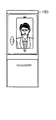
- FIG. 7A and 7B are diagrams illustrating an appearance of the information display terminal 10A according to the first modification.
- FIG. 7A is an external view in the front direction of the information display terminal 10A according to the first modification.
- FIG. 7B is an external view of the information display terminal 10 ⁇ / b> A in the first modification in the side surface direction.
- the information display terminal 10 ⁇ / b> A is a smart integrated case that is shorter and narrower in width than the information display terminal 10 in the above-described embodiment, and has a height similar to a human height (life size).
- a monitor base 213 is provided in the center of the front surface of the housing 212 so as to extend from the housing 212 to the front side.
- the first display panel 21A is disposed on the front surface of the upper portion of the housing 212 (the portion above the monitor base 213 in the figure). On the first display panel 21A, an operator's face image captured by the third camera 63 is displayed.
- an interphone 25z is arranged beside the first display panel 21A instead of the speaker and the microphone.
- a second camera 32A that captures the user's hand and a first camera 31A that captures the user's face image are arranged above and below the first display panel 21A, respectively. It is.
- a hood 214 is provided below the monitor base 213 so as to extend from both sides of the housing 212.
- a printer slot 40z through which printed paper is discharged is provided below the monitor table 213.
- the user can easily store baggage or the like in a space below the monitor base 213 and surrounded by the hood 214.
- the information display terminal 10A in the first modification has a life-size size, the user can face the operator's face image displayed on the first display panel 21A while standing. Therefore, the user can communicate with the operator from a more natural viewpoint.
- the space provided below the monitor base 213 can be used as a simple storage where temporary baggage can be placed, improving convenience.
- Modification 2 8A and 8B are diagrams illustrating an appearance of the information display terminal 10B according to the second modification.
- FIG. 8A is a perspective view illustrating an appearance of an information display terminal 10B according to the second modification.
- FIG. 8B is a diagram of the information display terminal 10 ⁇ / b> B according to the second modification viewed from the side.
- the information display terminal 10B has a slim casing 212B with a shorter depth than the information display terminal 10A in the first modification.
- a mountain-shaped base member 215 that supports the casing 212B so as not to fall down is provided at the lower end of the casing 212B.
- the housing 212B is inclined at a predetermined angle so as to lean toward the rear side with respect to the vertical direction.
- the display surface of the first display panel 21B faces slightly upward and more faces the operator's face, thereby improving the visibility of the user.
- the operation surface of the monitor base 213B is inclined downward by a predetermined angle (for example, 15 °) with respect to the horizontal direction.
- a predetermined angle for example, 15 °
- FIG. 9A and 9B are perspective views showing the appearance of information display terminals 10C and 10D having different sizes in Modification 3.
- FIG. 9A is a perspective view illustrating an appearance of an information display terminal 10C having a normal size according to the third modification.
- the information display terminal 10C has substantially the same size as the information display terminal 10A in the first modification, and unlike the information display terminal 10A, the monitor base 213C is inclined toward the front side by a predetermined angle. Therefore, the user can easily operate the operation surface of the second display panel 22C while standing and interacting while looking at the operator's face displayed on the first display panel 21C.
- FIG. 9B is an external view in the front direction of the low-size information display terminal 10D in the third modification.
- the information display terminal 10D is lower in height than the information display terminal 10D of a normal size, and the operator's line of sight is easy for a child or a user on a wheelchair. Therefore, the usability of children and users on wheelchairs is improved.
- the information display system 5 of the present embodiment is an information display system in which the information display terminal 10 that can be operated by the user and the information providing terminal 50 that can be operated by the operator are connected to be communicable.
- the information display terminal 10 includes information on the first camera 31 that captures the image of the user's face, the second camera 32 that captures the image of the user's hand, and data of the image of the user's face and the image of the user's hand.
- a communication control unit 20 (first communication unit) that receives the image of the operator's face and at least a part of the upper body and the image of the operator's hand transmitted to the providing terminal 50 and transmitted from the information providing terminal 50;
- a first display panel 21 that displays an image of the operator's face and at least a part of the upper body, and a second display panel 22 that displays an image of the operator's hand are provided.
- the information providing terminal 50 includes a third camera 63 that images the operator's face and at least a part of the upper body, a fourth camera 64 that images the operator's hand, and images of the operator's face and at least a part of the upper body.
- a communication control unit 60 (second communication unit) that transmits data with the image of the operator's hand to the information display terminal 10 and receives the image of the user's face and the image of the user's hand transmitted from the information display terminal 10. ), A third display panel 53 that displays the video of the user's face, and a fourth display panel 54 that displays the video of the user's hand. Above the fourth display panel 54, a half mirror 75 (reflecting means) that reflects the display content of the third display panel 53 toward the operator and transmits the incident light of the third camera 63 is oblique to the horizontal direction. It is attached at 45 ° (predetermined angle). A third camera 63 is disposed behind the half mirror 75.
- the operator has a conversation with the user while viewing the face image of the user projected by the third display panel 53 and projected on the half mirror 75.
- the third camera 63 disposed on the back of the half mirror 75 captures the operator's face image from the front through the half mirror 75.
- the face image of the operator facing the front is displayed on the first display panel 21 of the information display terminal 10.
- the information display system 5 can communicate with the user from a natural viewpoint while saving the installation equipment space in the arrangement of the terminal on the operator side.
- the third display panel 53 is disposed above the fourth display panel 54, and the half mirror 75 is disposed between the third display panel 53 and the fourth display panel 54.
- the length of the support base 112 in the depth direction can be shortened, and the support base 112 can be made compact.
- the half mirror 75 is attached so that the optical axis of the third camera 63 passes through the center of the half mirror 75.
- the third camera 63 captures the operator's face image so that the operator's line of sight is in front.
- the user can interact with the operator of the expression that is displayed on the first display panel 21 and that looks directly in front.
- the half mirror 75 is attached so that the optical axis of the third camera 63 passes through the upper end of the half mirror 75.
- the third camera 63 captures the operator's face image so that the operator's eyes are slightly downward.
- the user can interact with an operator who is displayed on the first display panel 21 and has a slightly looking down expression.
- the half mirror 75 is attached so that the optical axis of the third camera 63 passes through the lower end of the half mirror 75.
- the third camera 63 captures the operator's face image so that the operator's eyes are slightly upward.
- the user can interact with an operator who is displayed on the first display panel 21 and looks slightly up.
- the information display system of the second embodiment has almost the same configuration as that of the first embodiment.
- the description is abbreviate
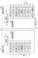
- FIG. 10 is a block diagram showing in detail an example of the internal configuration of the information display terminal 10 and the information providing terminal 50A in the second embodiment.
- the information providing terminal 50A of the second embodiment includes a display switching remote control 85 and a remote control receiving unit 83 that performs wireless connection with the remote control 85.
- control unit 51A in the information providing terminal 50A performs the third operation according to the instruction from the remote control 85 received by the remote control reception unit 83 or the selection of the switching menu 122 (see FIG. 11) displayed on the fourth display panel 54.
- a display switching control unit 51z that switches display contents on the display panel 53 and the fourth display panel 54 is provided.
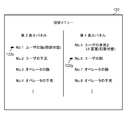
- FIG. 11 is a diagram showing the switching menu 122 displayed on the fourth display panel 54.
- the fourth display panel 54 displays a UI screen that allows touch operation. As part of the UI screen, the fourth display panel 54 displays a third display panel 53 and a switching menu 122 that can switch display contents displayed on the fourth display panel 54.
- a list of display items on the third display panel 53 and the fourth display panel 54 is displayed in a selectable manner.
- As display items of the third display panel 53 No. 1 User face (initial state), No. 2 User's hand, No. 3 Operator's face, No. 4 The operator's hand etc. can be selected.
- As display items on the fourth display panel 54 No. 5 User's hand and UI screen (initial state), No. 6 User's face, No. 7 Operator's face, No. 8 The operator's hand can be selected.
- one of the third display panel 53 and the fourth display panel 54 is fixed to the initial state and the other display item is selected or changed. However, both display items are selected or changed. An operation may be performed.
- the operator can select any display item of the switching menu 122 and switch the display content by directly touching the fourth display panel 54. .
- the operator may select a desired display item by operating the markers 122z and 122y of the switching menu 122 up and down using the remote controller 85.
- the operator may switch to a desired display item by directly specifying, for example, a number without using the switching menu 122.
- the first camera 31 on the information display terminal 10 side photographs the face of the user (customer).
- the second camera 32 on the information display terminal 10 side captures the user's hand.
- the third camera 63 on the information providing terminal 50A side captures the operator's face.
- the fourth camera 64 on the information providing terminal 50A side captures the operator's hand.
- the third display panel 53 on the information providing terminal 50A side is a small monitor, and normally displays the user's face image in the initial state.
- the fourth display panel 54 on the information providing terminal 50A side is a large monitor, and normally displays a user's hand image and a UI (user interface) screen in an initial state.
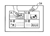
- FIGS 12A, 12B, and 12C are diagrams showing display screens of the third display panel 53 in each use case.
- the third display panel 53 on the information providing terminal 50A side normally displays the face image of the user.
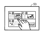
- the third display panel 53 displays a user's hand image captured by the second camera 32 on the information display terminal 10 side.
- the operator operates the UI screen displayed on the fourth display panel 54.
- FIG. 12A a situation as shown in FIG. 12A is assumed.
- a user customer
- brings a paper medium such as a storefront map, a leaflet, or a pamphlet and spreads it to his hand and makes an inquiry to the operator
- the second camera 32 images these paper medium.
- the operator operates the UI screen of the fourth display panel 54 while checking the information on the paper medium displayed on the third display panel 53, and searches for related information such as the presence / absence of inventory and the sales floor, and is appropriate for the user. Make a response.
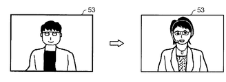
- the third display panel 53 displays an operator's face image (including the upper body) captured by the third camera 63 on the information providing terminal 50A side.
- the operator adjusts the focus, zoom, and the like of the third camera 63 while viewing his / her face image displayed on the third display panel 53.
- the focus of the operator's image captured by the third camera 63 may be slightly shifted depending on the physique of the operator and how to sit down.
- the operator appropriately sets the third camera 63 for the user (customer) while checking on the third display panel 53 how his / her face image is visible. Change to
- the third display panel 53 normally displays the user's face, and the operator is interacting with the user while looking at the third display panel 53. Even if you switch to your own face image, you can check your own image without changing your line of sight. Therefore, the operator can easily confirm the video of the operator actually viewed by the user by adjusting the third camera 63 while looking at the third display panel 53. Thereby, the 3rd camera 63 can be adjusted easily.
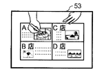
- the third display panel 53 displays the operator's hand image captured by the fourth camera 64, as shown in FIG. 12C.
- the operator adjusts the focus, zoom, and the like of the fourth camera 64 while looking at his / her hand image displayed on the third display panel 53.
- the operator When the information display system 5 is initially set, the operator focuses the fourth camera 64.
- the third display panel 53 displays a map or a flyer as an operator's hand image during dialogue with the user (customer), it is difficult to see the third display panel 53 by enlarging the fourth camera 64 by optical zoom. Maps and flyers become clearer. As a result, the user can check the contents of the map or flyer. Note that the operator may enlarge the fourth camera 64 and then return the settings (coordinates) and the like of the fourth camera 64 to preset values (initial positions) stored in advance.
- FIGS. 13A, 13B, and 13C are diagrams showing display screens of the fourth display panel 54 in each use case.
- the fourth display panel 54 normally displays the user's hand image and UI screen.
- the hand image includes a UI screen when there is a UI screen in the vicinity of the hand image.
- the fourth display panel 54 displays the user's hand image. Normally, the third display panel 53 displays the user's face image captured by the first camera 31, but it is difficult to confirm the contents of the range corresponding to the face image in the image captured by the second camera 32. , The fourth display panel 54 corresponds to this.
- the operator correctly displays the content of the product in the user's hand image captured by the second camera 32 installed above the information display terminal 10. It may not be confirmed.
- the operator instructs the first camera 31 installed below the information display terminal 10 by voice or the like so that the user can take an image by moving the product closer or away from the first camera 31, as shown in FIG. 13A.
- the operator can confirm the contents of the commodity imaged by the first camera 31 displayed on the fourth display panel 54.
- the fourth display panel 54 displays an operator's face image (including the upper body) captured by the third camera 63.
- the operator interacts with the user while confirming how his / her face image looks to the user (customer).
- the fourth display panel 54 displays the operator's hand image captured by the fourth camera 64.
- the operator interacts with the user while confirming how the user's hand image looks to the user.
- the operator adjusts the focus and zoom of the fourth camera 64.
- the fourth display panel 54 may display the operator's hand image and the UI screen at the same time.
- the operator's hand image may be displayed as a wipe image such as a small window. Is possible.
- the information display system 5A in the second embodiment is an information display system in which the information display terminal 10 that can be operated by the user and the information providing terminal 50A that can be operated by the operator are communicably connected.
- the information display terminal 10 includes information on the first camera 31 that captures the image of the user's face, the second camera 32 that captures the image of the user's hand, and data of the image of the user's face and the image of the user's hand.
- a communication control unit 20 (first communication unit) that receives the image of the operator's face and at least a part of the upper body and the image of the operator's hand transmitted to the providing terminal 50A and transmitted from the information providing terminal 50A;
- a first display panel 21 that displays an image of the operator's face and at least a part of the upper body, and a second display panel 22 that displays an image of the operator's hand are provided.
- the information providing terminal 50A includes a third camera 63 that images the operator's face and at least a part of the upper body, a fourth camera 64 that images the operator's hand, and images of the operator's face and at least a part of the upper body.
- a communication control unit 60 (second communication unit) that transmits data with the image of the operator's hand to the information display terminal 10 and receives the image of the user's face and the image of the user's hand transmitted from the information display terminal 10. ), A third display panel 53 that displays the video of the user's face, and a fourth display panel 54 that displays the video of the user's hand.
- the display switching control unit 51z switching processing unit displays the display content of the third display panel 53 from the video of the user's face captured by the first camera 31, the second camera 32, the third camera 63, and the fourth camera. 64, an instruction to switch to an image captured by any one of the cameras is given.
- the display content of the third display panel is displayed as the image of the face of the user. To other captured images. Therefore, it is possible to provide the user with a sense of reality that the user is actually facing the communication partner, thereby improving the usability of the operator.
- the display switching control unit 51z changes the display content of the fourth display panel 54 from the first camera 31, the third camera 63, and the fourth camera 64 from the image of the user's hand imaged by the second camera 32. An instruction to switch to an image captured by any camera is given. Thereby, the display content of the fourth display panel can be switched from the user's hand image to another captured image, and the convenience of the operator can be improved.
- the information display system 5 includes a remote controller 85 for switching the display.
- the display switching control unit 51z instructs switching by operating the remote controller 85. In this way, the switching instruction can be easily performed by using the remote controller. Further, it is possible to instruct switching of the display contents even in a place where the person who owns the remote control is away from the information providing terminal. Furthermore, even if the operator does not know the switching of the display contents, it is possible to instruct switching of the display contents instead.
- the fourth display panel 54 displays a switching menu 122.
- the display switching control unit 51z instructs switching by an operation on the switching menu 122. As a result, the operator can easily instruct switching while looking at the fourth display panel.
- the information display system has shown a case where the information display terminal and the information providing terminal communicate on a one-to-one basis.
- one-to-N, N-to-one, N-to-N N: plural
- the present disclosure can also be applied when communicating via a multipoint connection.
- the first display panel to the fourth display panel display a face image or a hand image captured by each camera in a plurality of terminals in a multi-screen display or a screen switching display. Also good.
- the first display panel to the fourth display panel may be capable of displaying a plurality of terminal information together.
- the display contents of the third display panel 53 and the fourth display panel 54 when the display contents of the third display panel 53 and the fourth display panel 54 are switched, one of the display contents is fixed and the other display contents can be arbitrarily switched.
- the display contents of both the display panel 53 and the fourth display panel 54 may be switched at the same time.
- a combination of these display contents may be registered in advance according to the use case.
- the information providing terminal may be configured such that the operator directly views the fourth display panel without using a prompter system, that is, without using a half mirror.
- the information display terminal projects at least part of the upper body as the most natural feeling when projecting at least part of the operator's face and upper body. You may project up to the elbow or waist area. Further, it is possible to project only up to the vicinity of the neck or the face without projecting almost the upper body. In addition, it is desirable that the face and a part of the upper body projected on the display panel are projected so as to match the actual size, which makes the feeling more natural. Further, when the information display terminal has a life-size display panel, the whole body of the operator may be projected. In this case, the operator may be in the same standing posture as the user or may be in a sitting posture.
- An information display system and an information providing terminal according to the present disclosure are capable of communicating with a natural viewpoint to a user while saving space of installed equipment in the arrangement of terminals on an operator side. It is useful as a providing terminal.
Landscapes
- Engineering & Computer Science (AREA)
- Multimedia (AREA)
- Signal Processing (AREA)
- Controls And Circuits For Display Device (AREA)
- Two-Way Televisions, Distribution Of Moving Picture Or The Like (AREA)
- User Interface Of Digital Computer (AREA)
Abstract
An information providing terminal includes a half mirror which is provided above a fourth display panel and which reflects a displayed content of a third display panel toward an operator while transmitting incident light on a third camera, the half mirror being inclined at 45 degrees relative to the horizontal direction. The third camera is placed rearwardly of the half mirror. The operator converses with a user while seeing a face image of the user projected by the third display panel and shown on the half mirror. The third camera placed behind the half mirror captures a face image of the operator from the front through the half mirror. At this moment, the face image of the frontward-looking operator is displayed on a first display panel of an information displaying terminal.
Description
本開示は、情報を表示する情報表示システム及び情報提供端末に関する。
This disclosure relates to an information display system and an information providing terminal that display information.
離れた場所にいる通信相手であるオペレータの使用端末との間で通信を行い、ユーザは、オペレータと対面しているような感覚で、種々の情報をやり取りするマルチメディア端末が知られている(例えば特許文献1参照)。
There is known a multimedia terminal that communicates with a terminal used by an operator who is a communication partner at a remote place and exchanges various information as if the user is facing the operator ( For example, see Patent Document 1).
特許文献1のマルチメディア端末は、カメラ及び3つのディスプレイを有し、カメラによりユーザの顔及び手元を撮像し、撮像した画像をオペレータの使用端末に送信する。また、マルチメディア端末は、3つのディスプレイのうち、第1のディスプレイにユーザの顔を表示し、第2のディスプレイにテキスト、静止画、動画等のマルチメディア情報を表示し、第3のディスプレイに文字・記号等を入力可能なタッチパネルや入力パネルを表示する。さらに、マルチメディア端末は、オペレータの使用端末との通話のためにマイク及びスピーカを有する。
The multimedia terminal of Patent Document 1 has a camera and three displays, images the user's face and hand with the camera, and transmits the captured image to the operator's terminal. Also, the multimedia terminal displays the user's face on the first display among the three displays, displays multimedia information such as text, still images, and moving images on the second display, and displays on the third display. Displays a touch panel or input panel that can input characters and symbols. Further, the multimedia terminal has a microphone and a speaker for a call with the operator's terminal.
ところが、ユーザが使用するマルチメディア端末とオペレータの使用端末との間の通信において、ユーザが使用するマルチメディア端末のディスプレイにオペレータの顔画像だけが表示されるのでは、ユーザがオペレータと実際にやり取りをしているような臨場感の提供が不十分である。
However, in communication between the multimedia terminal used by the user and the operator's terminal, if only the operator's face image is displayed on the display of the multimedia terminal used by the user, the user actually communicates with the operator. Insufficient provision of a sense of presence like
また、離れた場所にいるユーザとオペレータとが通話(会話)するシステム構成を検討した場合、オペレータ側において、オペレータの顔を撮像するカメラと、ユーザの顔の画像が表示されるオペレータ側のモニタとが離れて配置されていると、次のような不具合がある。即ち、オペレータはモニタを見ながらユーザと話をする際、カメラは、オペレータがモニタを見る角度とは違った角度からオペレータの顔を撮像することになる。この場合、ユーザ側に設けられるモニタ(つまり、オペレータの顔の画像が表示されるモニタ)には、オペレータの顔がユーザを見ている方向とは別の方向を見ているように映し出される。従って、ユーザは、オペレータとの間で、同一の方向を向く目線で話すような自然なコミュニケーションをとることが出来ず、不自然な対話となる。
In addition, when considering a system configuration in which a user and an operator at a remote location talk (conversely), an operator side camera on the operator side and an operator side monitor on which an image of the user's face is displayed If they are arranged apart from each other, there are the following problems. That is, when the operator talks to the user while looking at the monitor, the camera captures the operator's face from an angle different from the angle at which the operator looks at the monitor. In this case, a monitor provided on the user side (that is, a monitor on which an image of the operator's face is displayed) is projected as if the operator's face is looking in a direction different from the direction in which the user is looking. Therefore, the user cannot take a natural communication with the operator such as speaking with the line of sight facing the same direction, resulting in an unnatural dialogue.
一方で、ユーザとオペレータとの間で自然なコミュニケーションをとることができるためにオペレータ側の端末を配置するにあたり、モニタの設置場所にカメラを近づけて配置することも案外簡単ではなく、カメラの配置によってはモニタの設置位置との関係で無駄な空きスペースが生じてしまい、省スペース化を図ることが難しい。
On the other hand, since it is possible to communicate naturally between the user and the operator, it is not surprisingly easy to place the camera close to the monitor installation place when placing the terminal on the operator side. Depending on the position where the monitor is installed, there is a wasteful empty space, which makes it difficult to save space.
本開示は、オペレータ側の端末の配置において設置機器の省スペース化を図りつつ、ユーザに対して、自然な目線でコミュニケーションをとることを目的とする。
This disclosure is intended to communicate with the user from a natural viewpoint while saving the space of the installed equipment in the arrangement of terminals on the operator side.
本開示の情報表示システムは、ユーザが操作可能な情報表示端末と、オペレータが操作可能な情報提供端末とが通信可能に接続された情報表示システムであって、前記情報表示端末は、前記ユーザの顔を撮像する第1カメラと、前記ユーザの手元を撮像する第2カメラと、前記ユーザの顔の映像と前記ユーザの手元の映像とを前記情報提供端末に送信し、前記情報提供端末から送信された、前記オペレータの顔と上半身の少なくとも一部との映像と前記オペレータの手元の映像とを受信する第1通信部と、前記オペレータの顔と上半身の少なくとも一部との映像を表示する第1表示パネルと、前記オペレータの手元の映像を表示する第2表示パネルと、を備え、前記情報提供端末は、前記オペレータの顔と上半身の少なくとも一部とを撮像する第3カメラと、前記オペレータの手元を撮像する第4カメラと、前記オペレータの顔と上半身の少なくとも一部との映像と前記オペレータの手元の映像とを前記情報表示端末に送信し、前記情報表示端末から送信された、前記ユーザの顔の映像と前記ユーザの手元の映像とを受信する第2通信部と、前記ユーザの顔の映像を表示する第3表示パネルと、前記ユーザの手元の映像を表示する第4表示パネルと、を備え、前記第4表示パネルより上方に、前記第3表示パネルの表示内容を前記オペレータに向けて反射し、かつ前記第3カメラの入射光を透過する反射手段が所定角度で取り付けられ、前記反射手段の後方に前記第3カメラが配置される。
An information display system according to the present disclosure is an information display system in which an information display terminal that can be operated by a user and an information providing terminal that can be operated by an operator are connected to be able to communicate with each other. A first camera that captures a face, a second camera that captures the user's hand, a video of the user's face, and a video of the user's hand are transmitted to the information providing terminal and transmitted from the information providing terminal A first communication unit that receives the image of the operator's face and at least a part of the upper body and the image of the operator's hand, and displays an image of the operator's face and at least a part of the upper body. 1 display panel and a second display panel for displaying an image of the operator's hand, and the information providing terminal images at least a part of the operator's face and upper body A third camera that captures the operator's hand, a video of the operator's face and at least a part of the upper body, and a video of the operator's hand to the information display terminal. A second communication unit that receives a video of the user's face and a video of the user's hand transmitted from the display terminal; a third display panel that displays the video of the user's face; A fourth display panel for displaying an image, and reflects the display content of the third display panel toward the operator and transmits the incident light of the third camera above the fourth display panel. Reflecting means is attached at a predetermined angle, and the third camera is arranged behind the reflecting means.
また、本開示の情報提供端末は、ユーザが操作可能な情報表示端末との間で通信可能に接続され、オペレータが操作可能な情報提供端末であって、前記オペレータの顔と上半身の少なくとも一部とを撮像する第1カメラと、前記オペレータの手元を撮像する第2カメラと、前記オペレータの顔と上半身の少なくとも一部との映像と前記オペレータの手元の映像とを前記情報表示端末に送信し、前記情報表示端末から送信された、前記ユーザの顔の映像と前記ユーザの手元の映像とを受信する通信部と、前記ユーザの顔の映像を表示する第1表示パネルと、前記ユーザの手元の映像を表示する第2表示パネルと、を備え、前記第2表示パネルより上方に、前記第1表示パネルの表示内容を前記オペレータに向けて反射し、かつ前記第3カメラの入射光を透過する反射手段が所定角度で取り付けられ、前記反射手段の後方に前記第1カメラが配置される。
The information providing terminal according to the present disclosure is an information providing terminal that is communicably connected to an information display terminal that can be operated by a user and that can be operated by an operator, and is at least part of the face and upper body of the operator. A first camera that images the operator's hand, a video of the operator's face and at least a part of the upper body, and an image of the operator's hand are transmitted to the information display terminal. A communication unit that receives the video of the user's face and the video of the user's hand transmitted from the information display terminal, a first display panel that displays the video of the user's face, and the hand of the user A second display panel that displays the image of the first display panel, the display content of the first display panel being reflected toward the operator above the second display panel, and the third camera Reflecting means for transmitting the incident light is mounted at a predetermined angle, the first camera to the rear of the reflecting means is disposed.
本開示によれば、オペレータ側の端末の配置において設置機器の省スペース化を図りつつ、ユーザに対して、自然な目線でコミュニケーションをとることができる。
According to the present disclosure, it is possible to communicate with the user from a natural viewpoint while saving the space of the installed equipment in the arrangement of the terminal on the operator side.
以下、本開示に係る情報表示システム及び情報提供端末の各実施形態について、図面を参照して説明する。但し、必要以上に詳細な説明は省略する場合がある。例えば既によく知られた事項の詳細説明や実質的に同一の構成に対する重複説明を省略する場合がある。これは、以下の説明が不必要に冗長になるのを避け、当業者の理解を容易にするためである。なお、添付図面及び以下の説明は、当業者が本開示を十分に理解するために提供されるのであって、これらにより特許請求の範囲に記載の主題を限定することは意図されていない。
Hereinafter, embodiments of the information display system and the information providing terminal according to the present disclosure will be described with reference to the drawings. However, more detailed description than necessary may be omitted. For example, detailed descriptions of already well-known matters and repeated descriptions for substantially the same configuration may be omitted. This is to avoid the following description from becoming unnecessarily redundant and to facilitate understanding by those skilled in the art. The accompanying drawings and the following description are provided to enable those skilled in the art to fully understand the present disclosure, and are not intended to limit the subject matter described in the claims.
以下の各実施形態の情報表示システムは、例えば施設内に入場した顧客であるユーザが、場所が離れているオペレーションセンタで待機しているオペレータとコミュニケーションを行い、各種の案内をオペレータから受けることが可能なシステムに適用される。
In the information display system of each of the following embodiments, for example, a user who is a customer who has entered the facility communicates with an operator who is standing by at an operation center that is far away, and receives various guidance from the operator. Applies to possible systems.
(第1の実施形態)
図1は、第1の実施形態の情報表示システム5の概略構成の一例を示す図である。情報表示システム5は、ネットワーク90を介して接続された、ユーザ側の情報表示端末10と、オペレータ側の情報提供端末50とを含む構成を有する。情報表示端末10と情報提供端末50は、ネットワーク90を介して各種のデータ(テキストデータ、画像データ、音声データ等)を相互に通信可能である。 (First embodiment)
FIG. 1 is a diagram illustrating an example of a schematic configuration of aninformation display system 5 according to the first embodiment. The information display system 5 includes a user-side information display terminal 10 and an operator-side information providing terminal 50 that are connected via a network 90. The information display terminal 10 and the information providing terminal 50 can communicate various data (text data, image data, audio data, etc.) with each other via the network 90.
図1は、第1の実施形態の情報表示システム5の概略構成の一例を示す図である。情報表示システム5は、ネットワーク90を介して接続された、ユーザ側の情報表示端末10と、オペレータ側の情報提供端末50とを含む構成を有する。情報表示端末10と情報提供端末50は、ネットワーク90を介して各種のデータ(テキストデータ、画像データ、音声データ等)を相互に通信可能である。 (First embodiment)
FIG. 1 is a diagram illustrating an example of a schematic configuration of an
ネットワーク90には、インターネット等の広域通信網に接続される有線LAN(Local Area Network)や無線LAN、或いは専用線等が用いられる。また、情報表示端末10及び情報提供端末50のいずれも、ネットワーク90に接続された各種サーバ装置(不図示)とアクセス可能である。
As the network 90, a wired LAN (Local Area Network) connected to a wide area communication network such as the Internet, a wireless LAN, a dedicated line, or the like is used. In addition, both the information display terminal 10 and the information providing terminal 50 can access various server devices (not shown) connected to the network 90.
情報表示端末10は、人物の身長に合わせるように、ある程度の高さを有する箱形の架台12に載置される。架台12は、例えば情報表示端末10の筐体と同一色で塗装され、或いは情報表示端末10と共通のカバーで覆われることで、情報表示端末10と一体化される。情報表示端末10は、ユーザの顔と向き合うように上側に突出するように設けられた第1筐体15と、ユーザの手元(つまり、手、腕、掌、爪等のうち一部の部位を含む手の周囲。以下同様。)が接触可能なように手前に延出された第2筐体18とを有する。
The information display terminal 10 is placed on a box-shaped mount 12 having a certain height so as to match the height of the person. The gantry 12 is integrated with the information display terminal 10 by, for example, being painted in the same color as the casing of the information display terminal 10 or being covered with a cover common to the information display terminal 10. The information display terminal 10 includes a first housing 15 provided so as to protrude upward so as to face the user's face, and a part of the user's hand (that is, a hand, an arm, a palm, a nail, or the like). And a second housing 18 extended to the front so that the surrounding area of the hand can be contacted.
第1筐体15の前面には、後述する第3カメラ63によって撮像されるオペレータの顔と上半身の少なくとも一部との映像が映し出される第1表示パネル21が設けられる。第1表示パネル21には、実際とほぼ同じサイズで、オペレータの顔と上半身の少なくとも一部の映像が表示される。これにより、ユーザはオペレータと実際に対面しているような臨場感を得ることが可能となる。また、第1筐体15の前面上部には、ユーザの手元付近を撮像する第2カメラ32が設けられる。第1筐体15の前面下部、つまり第1表示パネル21と第2表示パネル22とが配置された筐体の中間部15zは、表示パネルが配置されないエリアとなっている。この中間部15zには、ユーザの顔及び上半身の少なくとも一部の映像を撮像する第1カメラ31が設けられる。また、中間部15zの両端付近には、オペレータが発した音声のデータを出力する左右一対のスピーカ25L,25R(出力機器の一例)が設けられる。中間部15zの中央付近には、ユーザが発した音声を収音するマイク27(入力機器の一例)が設けられる。第1表示パネル21と第2表示パネル22とが配置された筐体の中間部15zに、出力機器や入力機器が配置されることで、第1表示パネル21にオペレータが自然体で映し出され、一層臨場感が高まることが期待される。
On the front surface of the first housing 15, a first display panel 21 on which an image of an operator's face and at least a part of the upper body captured by a third camera 63 described later is displayed. On the first display panel 21, an image of at least a part of the operator's face and upper body is displayed with substantially the same size as the actual size. As a result, the user can obtain a sense of presence that is actually facing the operator. In addition, a second camera 32 that captures the vicinity of the user's hand is provided at the upper front of the first housing 15. A lower portion of the front surface of the first housing 15, that is, an intermediate portion 15 z of the housing in which the first display panel 21 and the second display panel 22 are disposed is an area in which the display panel is not disposed. The intermediate portion 15z is provided with a first camera 31 that captures images of at least a part of the user's face and upper body. Near the both ends of the intermediate portion 15z, a pair of left and right speakers 25L and 25R (an example of an output device) that outputs voice data emitted by an operator are provided. Near the center of the intermediate portion 15z, a microphone 27 (an example of an input device) that collects the voice uttered by the user is provided. The output device and the input device are arranged in the middle portion 15z of the casing in which the first display panel 21 and the second display panel 22 are arranged, so that the operator is naturally projected on the first display panel 21. Realism is expected to increase.
一方、第2筐体18の上面には、後述する第4カメラ64によって撮像されるオペレータの手元付近の映像やUI(User Interface)画面等が映し出される第2表示パネル22が設けられる。第2表示パネル22は、単に画像を表示するディスプレイ装置で構成されてもよいし、タッチ入力操作が可能なタッチパネルで構成されてもよい。第2表示パネル22がタッチパネルで構成される場合、タッチ入力された情報は、情報表示端末10からネットワーク90に接続される情報提供端末50や各種サーバ装置に伝送される。ここでは、第2表示パネル22がタッチパネルで構成される場合を示す。
On the other hand, on the upper surface of the second housing 18, a second display panel 22 on which an image near the operator's hand, a UI (User Interface) screen, and the like imaged by a fourth camera 64 described later is displayed. The second display panel 22 may be configured with a display device that simply displays an image, or may be configured with a touch panel capable of touch input operation. When the second display panel 22 is configured by a touch panel, the touch-input information is transmitted from the information display terminal 10 to the information providing terminal 50 connected to the network 90 and various server devices. Here, the case where the 2nd display panel 22 is comprised with a touch panel is shown.
また、第2筐体18の前端面18zには、第2表示パネル22に表示された画面のハードコピーを印刷可能なプリンタ40の排出口が配置される。プリンタ40の本体は架台12に内蔵される。また、第2筐体18の前端面18zには、ユーザの個人認証を行うための認証情報(例えばカード決済処理時に要求される、カードに関する各種情報や、PIN(Personal Identification Number)等の暗証番号)を読み取る読取装置42が設置される。
In addition, a discharge port of the printer 40 capable of printing a hard copy of the screen displayed on the second display panel 22 is disposed on the front end face 18z of the second casing 18. The main body of the printer 40 is built in the gantry 12. Further, the front end face 18z of the second housing 18 has authentication information for performing personal authentication of the user (for example, various information about the card required at the time of card settlement processing, and a personal identification number such as a PIN (Personal Identification Number)). ) Is installed.
一方、情報提供端末50は、操作デスク110を有する。操作デスク110を含む情報提供端末50の構造の詳細については、図3~図5を用いて後述するので、ここでは、簡単に説明する。なお、図1では、説明上、側板112x(図3参照)が外され、内部が見える状態である。
On the other hand, the information providing terminal 50 has an operation desk 110. Details of the structure of the information providing terminal 50 including the operation desk 110 will be described later with reference to FIGS. 3 to 5 and will be briefly described here. In FIG. 1, the side plate 112x (see FIG. 3) is removed for the sake of explanation, and the inside can be seen.
操作デスク110の前では、ヘッドセット73を装着したオペレータopが案内し易い姿勢でチェア71に座っている。ヘッドセット73は、情報提供端末50に接続され、ユーザが発した音声を出力し、オペレータが発した音声を収音する。
In front of the operation desk 110, the operator op wearing the headset 73 is sitting on the chair 71 in an easy-to-guide posture. The headset 73 is connected to the information providing terminal 50, outputs a voice uttered by the user, and collects a voice uttered by the operator.
操作デスク110の操作面には、コの字型又は門型の支持台112が固定されている。支持台112は、後述する電子部品を支持する。支持台112には、第1カメラ31によって撮像されたユーザの顔及び上半身の少なくとも一部の映像が映し出される第3表示パネル53と、オペレータopの顔及び上半身の少なくとも一部の映像を撮像する第3カメラ63とが支持される。
A U-shaped or gate-shaped support base 112 is fixed to the operation surface of the operation desk 110. The support base 112 supports electronic components to be described later. The support base 112 captures at least a part of the face and upper body of the operator op, and a third display panel 53 on which at least part of the face and upper part of the user imaged by the first camera 31 is projected. A third camera 63 is supported.
また、操作デスク110の操作面には、第2カメラ32によって撮像されたユーザの手元の映像を表示する第4表示パネル54がオペレータにとって視認し易くなるように傾斜して配置されている。第4表示パネル54の画面サイズは、第3表示パネル53に比べて大きく、オペレータopがユーザの手元を視認し易くなっている。第4表示パネル54は、単に画像を表示するディスプレイ装置で構成されてもよいし、タッチ入力操作が可能なタッチパネルで構成されてもよい。第4表示パネル54がタッチパネルで構成される場合、タッチ入力された情報は、情報提供端末50からネットワーク90に接続される情報表示端末10や各種サーバ装置に伝送される。ここでは、第4表示パネル54がタッチパネルで構成される場合を示す。
Also, on the operation surface of the operation desk 110, a fourth display panel 54 that displays an image of the user's hand imaged by the second camera 32 is disposed so as to be easily visible to the operator. The screen size of the fourth display panel 54 is larger than that of the third display panel 53, so that the operator op can easily see the user's hand. The fourth display panel 54 may be configured by a display device that simply displays an image, or may be configured by a touch panel capable of touch input operation. When the fourth display panel 54 is configured by a touch panel, the touch-input information is transmitted from the information providing terminal 50 to the information display terminal 10 connected to the network 90 and various server devices. Here, the case where the 4th display panel 54 is comprised with a touch panel is shown.
また、支持台112からオペレータ側に延出したバー57の中程には、オペレータopの手元を含む操作デスク110の操作面を撮像する第4カメラ64が設けられる。第4カメラ64は、オペレータopの手元を撮像する他、操作デスク110に載置された案内パンフレット等の資料を撮像可能である。また、情報提供端末50は、第4カメラ64で撮像された画像として、第4表示パネル54に表示されたWebサイトやUI画面等をキャプチャ可能である。また、デスク55には、キーボード、マウス等の操作部68やスキャナ69等が載置可能である。
In the middle of the bar 57 extending from the support base 112 to the operator side, a fourth camera 64 that images the operation surface of the operation desk 110 including the hand of the operator op is provided. The fourth camera 64 can image materials such as a guide pamphlet placed on the operation desk 110 in addition to imaging the hand of the operator op. Further, the information providing terminal 50 can capture a Web site, a UI screen, or the like displayed on the fourth display panel 54 as an image captured by the fourth camera 64. On the desk 55, an operation unit 68 such as a keyboard and a mouse, a scanner 69, and the like can be placed.
このように、ユーザ側の情報表示端末10は、情報提供端末50から受信した画像データを基に、第1表示パネル21にオペレータopの顔と上半身の少なくとも一部の映像を表示し、第2表示パネル22にオペレータopの手元の映像及びUI画面等を表示する。なお、第2表示パネル22は、オペレータopがデスク55の表面に案内パンフレット等の資料を載置すると、その資料も併せて表示する。また、情報表示端末10は、情報提供端末50から受信した音声データをスピーカ25L,25Rから出力し、マイク27で収音した音声データを情報提供端末50に送信する。
As described above, the information display terminal 10 on the user side displays the video of at least a part of the face and upper body of the operator op on the first display panel 21 based on the image data received from the information providing terminal 50, and the second The display panel 22 displays an image of the operator op, a UI screen, and the like. Note that when the operator op places a material such as a guide pamphlet on the surface of the desk 55, the second display panel 22 also displays the material. Further, the information display terminal 10 outputs the audio data received from the information providing terminal 50 from the speakers 25L and 25R, and transmits the audio data collected by the microphone 27 to the information providing terminal 50.
一方、オペレータ側の情報提供端末50は、情報表示端末10から受信した画像データを基に、第3表示パネル53にユーザの顔と上半身の少なくとも一部の映像を表示し、第4表示パネル54にユーザの手元の映像等を表示する。また、情報提供端末50は、情報表示端末10から受信した音声データをヘッドセット73のスピーカ73zから出力し、ヘッドセット73のマイク73yで収音した音声データを情報表示端末10に送信する。
On the other hand, based on the image data received from the information display terminal 10, the information providing terminal 50 on the operator side displays at least a part of the image of the user's face and upper body on the third display panel 53, and the fourth display panel 54. The image of the user's hand is displayed on the screen. The information providing terminal 50 outputs the audio data received from the information display terminal 10 from the speaker 73z of the headset 73, and transmits the audio data collected by the microphone 73y of the headset 73 to the information display terminal 10.
ここで、第3表示パネル53の表示可能領域は、ユーザの手元の映像等を表示する第4表示パネル54の表示可能領域よりも小さくてよい。これは、以下の理由による。オペレータにとって重要なのは、第4カメラ64により撮像されるオペレータopの手元にある情報(例えばパンフレット、地図など)をユーザに表示する第2表示パネル22に対して、ユーザが指示する箇所を、オペレータopがユーザと同程度の大きさで共有することである。ユーザの手元の映像等を表示する第4表示パネル54の表示可能領域は、ある程度の大きさを必要とする。さらには、第4表示パネル54の解像度や画素数も、ユーザ側の第2表示パネル22と同程度であることが望ましい。ただし、第4表示パネル54は、汎用のモニタであってもよい。これに対して、ユーザの顔(あるいは、それと上半身の少なくとも一部)を表示する第3表示パネル53は、オペレータopにとっては、ユーザの表情やその背景の状況がわかる程度であればよいので、その表示可能領域はそれほど大きなものでなくてよく、解像度、画素数についてもそれほど高いものを必要としない。
Here, the displayable area of the third display panel 53 may be smaller than the displayable area of the fourth display panel 54 that displays the image at hand of the user. This is due to the following reason. What is important for the operator is that the operator op indicates the location indicated by the user with respect to the second display panel 22 that displays information (for example, a brochure, a map, etc.) at hand of the operator op imaged by the fourth camera 64 to the user. Is sharing with the same size as the user. The displayable area of the fourth display panel 54 that displays the image at hand of the user needs a certain size. Furthermore, it is desirable that the resolution and the number of pixels of the fourth display panel 54 are approximately the same as those of the second display panel 22 on the user side. However, the fourth display panel 54 may be a general-purpose monitor. On the other hand, the third display panel 53 that displays the user's face (or at least a part of the upper body) only needs to be sufficient for the operator op to understand the user's facial expression and the background situation. The displayable area does not have to be so large, and the resolution and the number of pixels do not need to be so high.
そのため、第3表示パネル53の表示可能領域は、ユーザの手元の映像等を表示する第4表示パネル54の表示可能領域より小さくてよいし、第3表示パネル53の解像度や画素数についても、第4表示パネル54の解像度や画素数より小さくてよい。第3表示パネル53も、汎用のモニタであってよい。このことによって、オペレータop側の情報提供端末50のシステムは、汎用的なモニタと情報処理装置(PC(パーソナルコンピュータ)、タブレット端末等)又は受像機を用いて構成することが可能である。すなわち、オペレータop側の情報提供端末50は、ユーザ側の情報表示端末10よりも簡易な構成でありながら、ユーザとオペレータopとの間の自然かつスムーズなコミュニケーションを実現することができる。さらには、汎用的なモニタ及び装置により構成することで、各モニタ及び装置のレイアウトに自由度を有するので、異なるオペレータに対して、各モニタ及び装置を、常に最適な位置に配置することができる。
Therefore, the displayable area of the third display panel 53 may be smaller than the displayable area of the fourth display panel 54 that displays the image at hand of the user, and the resolution and the number of pixels of the third display panel 53 are as follows. The resolution and the number of pixels of the fourth display panel 54 may be smaller. The third display panel 53 may also be a general-purpose monitor. Thus, the system of the information providing terminal 50 on the operator op side can be configured using a general-purpose monitor and an information processing apparatus (PC (personal computer), tablet terminal, etc.) or a receiver. That is, the information providing terminal 50 on the operator op side has a simpler configuration than the information display terminal 10 on the user side, but can realize natural and smooth communication between the user and the operator op. Furthermore, since it is configured with general-purpose monitors and devices, the layout of each monitor and device has a degree of freedom, so that each monitor and device can always be placed at an optimal position for different operators. .
図2は、第1の実施形態の情報表示端末10及び情報提供端末50の内部構成の一例を詳細に示すブロック図である。情報表示端末10は、各部を統括的に制御する制御部11を有する。制御部11には、前述した第1表示パネル21、第1カメラ31、第2表示パネル22、第2カメラ32、読取装置42、左右のスピーカ25L,25R、マイク27及びプリンタ40の他、通信制御部20が接続される。
FIG. 2 is a block diagram illustrating in detail an example of the internal configuration of the information display terminal 10 and the information providing terminal 50 according to the first embodiment. The information display terminal 10 includes a control unit 11 that comprehensively controls each unit. In addition to the first display panel 21, the first camera 31, the second display panel 22, the second camera 32, the reading device 42, the left and right speakers 25L and 25R, the microphone 27, and the printer 40, the control unit 11 includes communication. The control unit 20 is connected.
第1表示パネル21は、オペレータopの顔及び上半身の一部を表示する、超高解像度な4K(つまり、3840画素×2160画素)のディスプレイを有する。なお、第1表示パネル21は、ユーザがタッチ入力可能なタッチパネルで構成されてもよい。
The first display panel 21 has an ultra-high resolution 4K display (that is, 3840 pixels × 2160 pixels) that displays the face of the operator op and a part of the upper body. In addition, the 1st display panel 21 may be comprised with the touchscreen which a user can touch-input.
第1カメラ31は、第1筐体15の下部に配置された内蔵カメラであり、情報表示端末10の前に立つユーザの顔と上半身の少なくとも一部の映像を撮像する。なお、第1カメラ31の画角は、オペレータ側の情報提供端末50から遠隔操作可能であってもよい。第1カメラ31には、高解像度なフルハイビジョンカメラ、ハイビジョンカメラ或いはノーマルカメラが用いられる。
The first camera 31 is a built-in camera disposed in the lower part of the first housing 15 and captures an image of at least a part of the face and upper body of the user standing in front of the information display terminal 10. Note that the angle of view of the first camera 31 may be remotely operable from the information providing terminal 50 on the operator side. As the first camera 31, a high-resolution full high-definition camera, high-definition camera, or normal camera is used.
第2表示パネル22は、インタラクティブな表示パネルとして、4Kディスプレイを有するタッチパネルで構成され、オペレータopの手元の映像、操作メニュー画面、アプリ画面、ウェブサイト、各種ドキュメント等を表示し、タッチ操作によるボタン押下、手書き入力等を受け付ける。また、第2表示パネル22は、画面表示の拡大・縮小の指示を、ユーザの指又はスタイラスペンによる入力操作を受け付ける。
The second display panel 22 is configured as a touch panel having a 4K display as an interactive display panel, displays an image of an operator op, an operation menu screen, an application screen, a website, various documents, etc., and is a button by a touch operation. Accepts pressing, handwriting input, and the like. The second display panel 22 accepts an input operation with a user's finger or stylus pen for an instruction to enlarge or reduce the screen display.
第2カメラ32は、第1筐体15の上部に配置された内蔵カメラであり、第2表示パネル22の周囲に画角が固定され、ユーザが第2表示パネル22に対し操作する手元の映像等を撮像する。第2カメラ32は、4K或いはフルハイビジョンの高解像度カメラであることが望ましい。さらに、第2カメラ32がPTZカメラである場合、所望の箇所にズームアップすることで、細部まで視認できるように撮像可能である。
The second camera 32 is a built-in camera disposed at the top of the first housing 15, and has a field angle fixed around the second display panel 22, and a video of a user operating the second display panel 22 at hand. And so on. The second camera 32 is preferably a 4K or full high vision high resolution camera. Furthermore, when the 2nd camera 32 is a PTZ camera, it can image so that it can visually recognize to a detail by zooming in on a desired location.
スピーカ25L,25Rは、情報表示端末10の前にいるユーザが聞き取り易くなるような指向性を有するステレオスピーカであり、オペレータopが発する音声等を出力する。マイク27は、ユーザに対し指向方向を有する指向性マイクであり、ユーザが発する音声を収音する。なお、マイク27及びスピーカ25L,25Rはヘッドセットで構成されてもよく、ユーザが情報表示端末10を操作する際、このヘッドセットを頭部に装着する。
Speakers 25L and 25R are stereo speakers having directivity that makes it easy for the user in front of the information display terminal 10 to hear, and outputs sound or the like emitted by the operator op. The microphone 27 is a directional microphone having a directivity direction with respect to the user, and collects sound emitted by the user. Note that the microphone 27 and the speakers 25L and 25R may be configured as a headset, and when the user operates the information display terminal 10, the headset is attached to the head.
プリンタ40は、第2表示パネル22の画面をハードコピーとして印刷可能であり、モノクロ印刷或いはカラー印刷のいずれかで印刷する。また、印刷方式としては、インクジェット方式、レーザプリント方式、静電記録方式等が採用される。
The printer 40 can print the screen of the second display panel 22 as a hard copy, and prints by either monochrome printing or color printing. As a printing method, an ink jet method, a laser printing method, an electrostatic recording method, or the like is employed.
第1通信部の一例としての通信制御部20は、情報提供端末50の通信制御部60とネットワーク90を介してセキュア通信を行うネットワークI/Fである。具体的には、通信制御部20は、第1カメラ31により撮像されたユーザの顔の映像と第2カメラ32により撮像されたユーザの手元の映像とのデータを情報提供端末50に送信する。また通信制御部20は、情報提供端末50から送信された、オペレータの顔と上半身の少なくとも一部との映像とオペレータの手元の映像とを受信する。
The communication control unit 20 as an example of the first communication unit is a network I / F that performs secure communication with the communication control unit 60 of the information providing terminal 50 via the network 90. Specifically, the communication control unit 20 transmits data of the user's face image captured by the first camera 31 and the user's hand image captured by the second camera 32 to the information providing terminal 50. Further, the communication control unit 20 receives the image of the operator's face and at least a part of the upper body and the image of the operator's hand transmitted from the information providing terminal 50.
読取装置42は、ユーザの個人情報を読み取る。読取装置42として、例えばNFC(Near Field Communication)等の近距離非接触通信によりICタグの情報を読み取る非接触リーダライタ装置や、スロットに挿入されたICカードの情報を読み取るICカードリーダライタ装置が挙げられる。なお、指紋や静脈等のパターンで個人認証を行う生体認証装置が用いられてもよい。また、読取装置42により読み取られたユーザの個人情報は、認証情報として、決済処理や電子マネーに使用されてもよい。個人認証を行うことで、利便性を高めるとともに、なりすまし等を排除できる。
The reading device 42 reads the user's personal information. As the reading device 42, for example, a non-contact reader / writer device that reads information on an IC tag by near-field non-contact communication such as NFC (Near Field Communication), or an IC card reader / writer device that reads information on an IC card inserted into a slot. Can be mentioned. Note that a biometric authentication device that performs personal authentication using a pattern such as a fingerprint or a vein may be used. In addition, the personal information of the user read by the reading device 42 may be used as payment information or electronic money as authentication information. By performing personal authentication, convenience can be improved and spoofing can be eliminated.
なお、情報表示端末10は、多言語対応型の端末であり、ユーザが予め第2表示パネル22に表示された言語を選択すると、オペレータopが発する音声を、選択された言語に自動翻訳して、スピーカ25L,25Rから出力する。また、情報表示端末10は、オペレータが発した音声をテキストとして表示する機能、手書き入力された文字を認識するOCR機能等も有する。
Note that the information display terminal 10 is a multilingual terminal, and when a user selects a language displayed on the second display panel 22 in advance, a voice uttered by the operator op is automatically translated into the selected language. And output from the speakers 25L and 25R. The information display terminal 10 also has a function of displaying voices uttered by an operator as text, an OCR function for recognizing handwritten characters, and the like.
一方、情報提供端末50は、各部を統括的に制御する制御部51を有する。制御部51には、前述した第3表示パネル53、第3カメラ63、第4表示パネル54、第4カメラ64、操作部68、ヘッドセット73のスピーカ73z,マイク73y及びスキャナ69の他、通信制御部60が接続される。
On the other hand, the information providing terminal 50 includes a control unit 51 that controls each unit in an integrated manner. In addition to the third display panel 53, the third camera 63, the fourth display panel 54, the fourth camera 64, the operation unit 68, the speaker 73z of the headset 73, the microphone 73y, and the scanner 69, the control unit 51 includes communication. A control unit 60 is connected.
第3表示パネル53は、ユーザの顔及び上半身の少なくとも一部の映像を表示するディスプレイを有する。第3表示パネル53は、4Kに限らず、ノーマル、ハイビジョン或いはフルハイビジョンディスプレイであってもよい。なお、第3表示パネル53は、オペレータopがタッチ入力可能なタッチパネルで構成されてもよい。
The third display panel 53 has a display for displaying at least part of the image of the user's face and upper body. The third display panel 53 is not limited to 4K, and may be a normal, high-definition or full high-definition display. Note that the third display panel 53 may be configured with a touch panel that allows an operator op to perform touch input.
第3カメラ63は、フレーム112Zに取り付けられたカメラであり、情報表示端末10の第1表示パネル21に表示される、オペレータopの顔及び上半身の少なくとも一部の映像を撮像するので、超高解像度な4Kカメラであることが望ましい。
The third camera 63 is a camera attached to the frame 112Z, and images at least a part of the face and upper body of the operator op displayed on the first display panel 21 of the information display terminal 10. It is desirable that the resolution is a 4K camera.
第4表示パネル54は、インタラクティブな表示パネルとして、4Kディスプレイを有するタッチパネルで構成され、ユーザの手元の映像、操作メニュー画面、アプリ画面、ウェブサイト、各種ドキュメント等を表示し、タッチ操作によるボタン押下等を受け付ける。また、第4表示パネル54は、画面表示の拡大・縮小の指示を、オペレータopの指又はスタイラスペンによる入力操作を受け付ける。
The fourth display panel 54 is composed of a touch panel having a 4K display as an interactive display panel. The fourth display panel 54 displays a user's image, an operation menu screen, an application screen, a website, various documents, and the like, and a button is pressed by a touch operation. Etc. are accepted. Further, the fourth display panel 54 receives an input operation with an operator op's finger or stylus pen for an instruction to enlarge or reduce the screen display.
第4カメラ64は、バー57に取り付けられたカメラであり、デスク55の表面に置かれたオペレータopの手元の映像やパンフレット等を撮像する。第4カメラ64は、第2表示パネル22に表示される手元等の画像を撮像するので、超高解像度な4Kカメラであることが望ましい。さらに、PTZカメラである場合、細部を視認可能に撮像することができる。
The fourth camera 64 is a camera attached to the bar 57, and picks up images, pamphlets, and the like at hand of the operator op placed on the surface of the desk 55. The fourth camera 64 captures an image of a hand or the like displayed on the second display panel 22, and is preferably a 4K camera with an ultra-high resolution. Furthermore, in the case of a PTZ camera, details can be imaged so as to be visible.
操作部68は、オペレータopが操作可能なマウスやキーボード等の入力デバイスである。スキャナ69は、パンフレット等に対し読み取り走査を行う。
The operation unit 68 is an input device such as a mouse or a keyboard that can be operated by the operator op. The scanner 69 scans a pamphlet or the like.
ヘッドセット73は、オペレータopの頭部に装着され、オペレータopが発する音声を収音するマイク73y、及びユーザが発する音声等を出力する左右一対のスピーカ73zを有する。なお、左右一対のスピーカ及びマイクは、ヘッドセットとして一体化される以外に、それぞれスタンドアローン型の筐体を有するものであってもよい。
The headset 73 is attached to the head of the operator op, and has a microphone 73y that collects a sound emitted by the operator op, and a pair of left and right speakers 73z that outputs a sound emitted by the user. Note that the pair of left and right speakers and microphones may each have a stand-alone casing, in addition to being integrated as a headset.
第2通信部の一例としての通信制御部60は、情報表示端末10の通信制御部20とネットワーク90を介してセキュア通信を行うネットワークI/Fである。具体的には、通信制御部60は、第3カメラ63により撮像されたオペレータの顔と上半身の少なくとも一部との映像と第4カメラ64により撮像されたオペレータの手元の映像とのデータを情報表示端末10に送信する。また通信制御部60は、情報表示端末10から送信された、ユーザの顔の映像とユーザの手元の映像とを受信する。
The communication control unit 60 as an example of the second communication unit is a network I / F that performs secure communication with the communication control unit 20 of the information display terminal 10 via the network 90. Specifically, the communication control unit 60 stores data of the video of the operator's face and at least a part of the upper body captured by the third camera 63 and the video of the operator's hand captured by the fourth camera 64. It transmits to the display terminal 10. Further, the communication control unit 60 receives the image of the user's face and the image of the user's hand transmitted from the information display terminal 10.
図3は、情報提供端末50の外観例を示す斜視図である。図4は、天板112y及び片側の側板112xを外した状態の情報提供端末50の内部の配置例を示す斜視図である。図5は、天板112y及び片側の側板112xを外した状態の情報提供端末50の内部を側方から見た図である。
FIG. 3 is a perspective view showing an example of the appearance of the information providing terminal 50. FIG. 4 is a perspective view showing an example of the arrangement inside the information providing terminal 50 with the top plate 112y and one side plate 112x removed. FIG. 5 is a side view of the inside of the information providing terminal 50 with the top plate 112y and one side plate 112x removed.
前述したように、情報提供端末50は、操作デスク110を主要な構成要素とし、この操作デスク110に、第3表示パネル53、第4表示パネル54、ハーフミラー75、第3カメラ63、及び第4カメラ64が配置された構成を有する。
As described above, the information providing terminal 50 includes the operation desk 110 as a main component, and the operation desk 110 includes the third display panel 53, the fourth display panel 54, the half mirror 75, the third camera 63, and the third display panel. It has a configuration in which four cameras 64 are arranged.
操作デスク110の操作面には、門形の支持台112が固定される。支持台112は、略箱型に組まれたフレーム112zに、天板112y、2枚の側板112x及び背面板112wが取り付けられた構造を有する。支持台112の、オペレータと対向する面は開放されている。なお、図4及び図5では、支持台112の内部を分かり易くするために、便宜上、1枚の側板112xと天板112yが外されている。
A gate-shaped support base 112 is fixed to the operation surface of the operation desk 110. The support base 112 has a structure in which a top plate 112y, two side plates 112x, and a back plate 112w are attached to a frame 112z assembled in a substantially box shape. The surface of the support 112 facing the operator is open. 4 and 5, in order to make the inside of the support base 112 easy to understand, one side plate 112x and the top plate 112y are removed for convenience.
操作デスク110の操作面には、第4表示パネル54が後側(オペレータと反対側)に例えば45°斜めに傾けた状態で取り付けられており、オペレータが視認し易くなる。第4表示パネル54には、例えば第4表示パネル54に表示される表示内容を切替可能な切替メニュー122が表示される。第4表示パネル54は、タッチパネルで構成されており、ユーザが第4表示パネル54に直接にタッチすることで切替メニュー122を操作してもよいし、マウスを用いて切替メニュー122を操作してもよい。
On the operation surface of the operation desk 110, the fourth display panel 54 is attached to the rear side (opposite to the operator), for example, with an inclination of 45 °, so that the operator can easily see. On the fourth display panel 54, for example, a switching menu 122 capable of switching display contents displayed on the fourth display panel 54 is displayed. The fourth display panel 54 is configured by a touch panel, and the user may operate the switching menu 122 by directly touching the fourth display panel 54 or may operate the switching menu 122 using a mouse. Also good.
また、支持台112の背面板側のフレーム112zには、オペレータを撮像可能な第3カメラ63が固定される。また、支持台112の天板側のフレーム112zには、第3表示パネル53が固定される。支持台112の内部中央には、ハーフミラー75が斜めに突出したフレーム112zに支持されるように取り付けられる。
Also, a third camera 63 capable of imaging the operator is fixed to the frame 112z on the back plate side of the support base 112. The third display panel 53 is fixed to the frame 112z on the top plate side of the support base 112. A half mirror 75 is attached to the center of the support base 112 so as to be supported by a frame 112z protruding obliquely.
反射手段としてのハーフミラー75は、第3表示パネル53に映し出された映像による光をオペレータ側に反射し、また、オペレータ側からの第3カメラ63への入射光を透過するように、所定角度(本実施形態では、例えば操作面に対して45°)傾斜して取り付けられる。本実施形態では、ハーフミラー75と、第3表示パネル53と、第3カメラ63とで、プロンプターシステムとしての機能が構成される。
The half mirror 75 as the reflecting means reflects the light from the image projected on the third display panel 53 to the operator side, and transmits the incident light to the third camera 63 from the operator side at a predetermined angle. (In this embodiment, it is attached with an inclination of 45 ° with respect to the operation surface, for example). In the present embodiment, the half mirror 75, the third display panel 53, and the third camera 63 constitute a function as a prompter system.
一般的に、プロンプターは、オペレータに対して所定角度に傾斜して配置された透明ガラス板を有し、例えば下方に置かれた表示器(モニタ、PC等)に表示される文字等の情報を透明なガラス板に投影し、この透明なガラス板が文字等の情報をオペレータ側に反射させることで、オペレータに文字等の情報を視認させる。本実施形態では、ハーフミラー75は透明ガラス板でできている。
In general, a prompter has a transparent glass plate arranged at a predetermined angle with respect to an operator, for example, information such as characters displayed on a display (monitor, PC, etc.) placed below. By projecting on a transparent glass plate, and this transparent glass plate reflects information such as characters to the operator side, the operator can visually recognize the information such as characters. In the present embodiment, the half mirror 75 is made of a transparent glass plate.
また、支持台112の2枚の側板112x、天板112y及び背面板112wは、ハーフミラー75に入射する外光を遮るフード(覆い)として機能する。つまり、第4表示パネル54、第3表示パネル53及びハーフミラー75は、天板112y、2枚の側板112x及び背面板112wによって前面を除き覆われるので、外光を遮ることができる。これにより、第4表示パネル54、第3表示パネル53及びハーフミラー75に映し出される映像の視認性が確保される。
Further, the two side plates 112x, the top plate 112y, and the back plate 112w of the support base 112 function as a hood (cover) that blocks outside light incident on the half mirror 75. That is, the fourth display panel 54, the third display panel 53, and the half mirror 75 are covered except for the front surface by the top plate 112y, the two side plates 112x, and the back plate 112w, and thus can block outside light. Thereby, the visibility of the image | video projected on the 4th display panel 54, the 3rd display panel 53, and the half mirror 75 is ensured.
また、本実施形態では、第4表示パネル54の中心と、ハーフミラー75の中心と、第3表示パネル53の中心とが、略同一の鉛直線上に位置するように、第4表示パネル54、ハーフミラー75及び第3表示パネル53が配置される。ハーフミラー75の中心と第3表示パネル53の中心とが略同一の鉛直線上に位置することで、ハーフミラー75のサイズを必要以上に大きくすることなく、ハーフミラー75は、第3表示パネル53に映し出された映像を欠くことなくオペレータに向けることができる。
In the present embodiment, the fourth display panel 54, the center of the fourth display panel 54, the center of the half mirror 75, and the center of the third display panel 53 are positioned on substantially the same vertical line. A half mirror 75 and a third display panel 53 are arranged. Since the center of the half mirror 75 and the center of the third display panel 53 are located on substantially the same vertical line, the half mirror 75 can be used in the third display panel 53 without increasing the size of the half mirror 75 more than necessary. The video displayed on the screen can be directed to the operator without missing.
また、支持台112の上部に配されたフレーム112zの一部としてオペレータ側に延びたバー57には、第4カメラ64がオペレータの手元を写し易いように取り付けられる。
Further, the fourth camera 64 is attached to the bar 57 extending to the operator side as a part of the frame 112z arranged on the upper part of the support base 112 so that the operator's hand can be easily captured.
情報提供端末50は、ハーフミラー75の上部に第3表示パネル53が配置され、ハーフミラー75の背部に第3カメラ63が配置される、プロンプターシステムの配置とは異なる、逆配置の構造を有する。逆配置では、ハーフミラー75は、第3表示パネル53と第4表示パネル54との間に配置される。一方、プロンプターでは、通常、ハーフミラーの下方に第3表示パネルに相当するモニタが配置される。
The information providing terminal 50 has a reverse arrangement structure, which is different from the prompter system arrangement, in which the third display panel 53 is arranged above the half mirror 75 and the third camera 63 is arranged behind the half mirror 75. . In the reverse arrangement, the half mirror 75 is arranged between the third display panel 53 and the fourth display panel 54. On the other hand, in the prompter, a monitor corresponding to the third display panel is usually arranged below the half mirror.
なお、情報提供端末50は、通常のプロンプターと同様、ハーフミラー75の下方に配置され、かつ、第4表示パネル54の奥側に第3表示パネル53が取り付けられる、通常配置の構造を有してもよい。通常配置では、ハーフミラー75は、第3表示パネル53と第4表示パネル54の上方に配置される。また、通常配置におけるハーフミラー75の傾斜角度は、逆配置におけるハーフミラー75の傾斜角度と水平方向に対して反対向きであり、オペレータ側に対して反射面が浮くような角度である。
Note that the information providing terminal 50 has a normal arrangement structure in which the third display panel 53 is attached to the back side of the fourth display panel 54 as well as the normal prompter. May be. In the normal arrangement, the half mirror 75 is arranged above the third display panel 53 and the fourth display panel 54. Further, the inclination angle of the half mirror 75 in the normal arrangement is opposite to the inclination angle of the half mirror 75 in the reverse arrangement with respect to the horizontal direction, and is an angle such that the reflection surface floats with respect to the operator side.
この通常配置では、第3表示パネル53は、第4表示パネル54の奥に配置されるので、支持台112の奥行き方向の長さが長くなる。このため、支持台が大きくなり、コンパクト化が困難となる。また、支持台の内側の上部にも、使用されていない無駄な空間が生まれる。
In this normal arrangement, the third display panel 53 is arranged in the back of the fourth display panel 54, so that the length of the support base 112 in the depth direction becomes long. For this reason, a support stand becomes large and it becomes difficult to make compact. In addition, a wasteful space that is not used is also created in the upper part inside the support base.
一方、逆配置では、通常配置と比べ、第3表示パネル53が取り付けられる支持台112の内側の上部を無駄な空間として空けておくことなく、有効に活用できる。その分、支持台112の奥行き方向の長さを短くでき、支持台112をコンパクト化できる。
On the other hand, in the reverse arrangement, compared to the normal arrangement, the upper portion inside the support base 112 to which the third display panel 53 is attached can be effectively used without leaving a useless space. Accordingly, the length of the support base 112 in the depth direction can be shortened, and the support base 112 can be made compact.
なお、逆配置の場合に第3表示パネル53に映し出される映像の向きと、通常配置の場合に第3表示パネル53に映し出される映像の向きとは、180度反対となるように第3表示パネル53を取り付けることで、オペレータ側に投影される映像の向きを揃えることができる。
Note that the third display panel is configured such that the direction of the image displayed on the third display panel 53 in the reverse arrangement is opposite to the direction of the image displayed on the third display panel 53 in the normal arrangement. By attaching 53, the direction of the image projected on the operator side can be made uniform.
図6A、図6B及び図6Cは、ハーフミラー75と第3カメラ63との位置関係を示す図である。
6A, 6B, and 6C are diagrams showing the positional relationship between the half mirror 75 and the third camera 63. FIG.
図6Aでは、ハーフミラー75の下端に第3カメラ63の光軸が位置するように、ハーフミラー75と第3カメラ63が取り付けられる。第3表示パネル53からの映像がハーフミラー75の中央に映し出される場合、オペレータの目線が僅かに上向きになるように、第3カメラ63はオペレータの顔画像を撮像することになる。これにより、ユーザは、第1表示パネル21に表示される、若干、見上げるような表情のオペレータと対話することができる。
In FIG. 6A, the half mirror 75 and the third camera 63 are attached so that the optical axis of the third camera 63 is positioned at the lower end of the half mirror 75. When the video from the third display panel 53 is projected in the center of the half mirror 75, the third camera 63 captures the operator's face image so that the operator's eyes are slightly upward. As a result, the user can interact with an operator who is displayed on the first display panel 21 and looks slightly up.
図6Bでは、ハーフミラー75の中心に第3カメラ63の光軸が位置するように、ハーフミラー75と第3カメラ63が取り付けられる。第3表示パネル53からの映像がハーフミラー75の中央に映し出される場合、オペレータの目線が正面になるように、第3カメラ63はオペレータの顔画像を撮像することになる。これにより、ユーザは、第1表示パネル21に表示される、真正面に見える表情のオペレータと対話することができる。
6B, the half mirror 75 and the third camera 63 are attached so that the optical axis of the third camera 63 is positioned at the center of the half mirror 75. When the video from the third display panel 53 is projected in the center of the half mirror 75, the third camera 63 captures the operator's face image so that the operator's line of sight is in front. Thereby, the user can interact with the operator of the expression that is displayed on the first display panel 21 and that looks directly in front.
図6Cでは、ハーフミラー75の上端に第3カメラ63の光軸が位置するように、ハーフミラー75と第3カメラ63が取り付けられる。第3表示パネル53からの映像がハーフミラー75の中央に映し出される場合、オペレータの目線が僅かに下向きになるように、第3カメラ63はオペレータの顔画像を撮像することになる。これにより、ユーザは、第1表示パネル21に表示される、若干、見下ろすような表情のオペレータと対話することができる。
6C, the half mirror 75 and the third camera 63 are attached so that the optical axis of the third camera 63 is positioned at the upper end of the half mirror 75. When the video from the third display panel 53 is projected in the center of the half mirror 75, the third camera 63 captures the operator's face image so that the operator's eyes are slightly downward. Thus, the user can interact with an operator who is displayed on the first display panel 21 and has a slightly looking down expression.
上記構造を有する情報提供端末50では、オペレータは、ハーフミラー75に映し出されるユーザの顔画像を見ながらユーザと会話をする。ハーフミラー75の背部に配された、第3カメラ63は、ハーフミラー75越しにオペレータの顔画像を正面から撮像する。この時、情報表示端末10の第1表示パネル21には、正面を向くオペレータの顔画像が映し出される。これにより、ユーザは、オペレータが自分と目線を合わせて話しているかのような印象を受けるので、臨場感に溢れた対話が可能となる。
In the information providing terminal 50 having the above structure, the operator has a conversation with the user while viewing the user's face image displayed on the half mirror 75. The third camera 63 disposed on the back of the half mirror 75 captures the operator's face image from the front through the half mirror 75. At this time, the face image of the operator facing the front is displayed on the first display panel 21 of the information display terminal 10. As a result, the user feels as if the operator is talking with himself / herself, so that a dialogue with a sense of reality is possible.
また、オペレータが、ハーフミラー75の下方に位置する第4表示パネル54に視線を僅かに移し、第4表示パネル54に表示されるユーザの手元の画像を見ながら、第4表示パネル54に対してタッチパネルあるいはマウス等で操作する。この時、第4カメラ64は、オペレータの手元付近を撮像する。また、情報表示端末10の第2表示パネル22には、第4カメラ64で撮像された、オペレータの手元付近の画像が映し出される。ユーザは、第1表示パネル21に映し出される、オペレータが僅かに視線を下にしている様子を見ながら、第2表示パネル22に映し出されるオペレータの手元付近の画像を見ることができる。これにより、ユーザは、会話中、オペレータが目前で操作しているかのような印象を受けるので、臨場感に溢れた応対が可能となる。
In addition, the operator slightly shifts his / her line of sight to the fourth display panel 54 located below the half mirror 75 and looks at the image of the user's hand displayed on the fourth display panel 54 while viewing the fourth display panel 54. Operate with touch panel or mouse. At this time, the fourth camera 64 captures the vicinity of the operator's hand. The second display panel 22 of the information display terminal 10 displays an image near the operator's hand that is captured by the fourth camera 64. The user can view an image near the operator's hand displayed on the second display panel 22 while watching the operator appearing slightly on the first display panel 21 while the operator is slightly looking down. As a result, during the conversation, the user receives an impression as if the operator is operating in front of him / her, so that he / she can respond with a sense of reality.
(変形例1)
図7A及び図7Bは、変形例1における情報表示端末10Aの外観を示す図である。図7Aは、変形例1における情報表示端末10Aの正面方向の外観図である。図7Bは、変形例1における情報表示端末10Aの側面方向の外観図である。情報表示端末10Aは、前記実施形態における情報表示端末10と比べ、奥行きが短くかつ幅が狭く、また、高さが人間の身長と同程度である(等身大)、スマートな一体型の筐体212を有する。筐体212の前面中央には、モニタ台213が筐体212から手前側に延出して設けられている。また、筐体212の上部(図中、モニタ台213より上の部分)の前面には、第1表示パネル21Aが配置される。第1表示パネル21Aには、第3カメラ63で撮像されたオペレータの顔画像が表示される。 (Modification 1)
7A and 7B are diagrams illustrating an appearance of theinformation display terminal 10A according to the first modification. FIG. 7A is an external view in the front direction of the information display terminal 10A according to the first modification. FIG. 7B is an external view of the information display terminal 10 </ b> A in the first modification in the side surface direction. The information display terminal 10 </ b> A is a smart integrated case that is shorter and narrower in width than the information display terminal 10 in the above-described embodiment, and has a height similar to a human height (life size). 212. A monitor base 213 is provided in the center of the front surface of the housing 212 so as to extend from the housing 212 to the front side. In addition, the first display panel 21A is disposed on the front surface of the upper portion of the housing 212 (the portion above the monitor base 213 in the figure). On the first display panel 21A, an operator's face image captured by the third camera 63 is displayed.
図7A及び図7Bは、変形例1における情報表示端末10Aの外観を示す図である。図7Aは、変形例1における情報表示端末10Aの正面方向の外観図である。図7Bは、変形例1における情報表示端末10Aの側面方向の外観図である。情報表示端末10Aは、前記実施形態における情報表示端末10と比べ、奥行きが短くかつ幅が狭く、また、高さが人間の身長と同程度である(等身大)、スマートな一体型の筐体212を有する。筐体212の前面中央には、モニタ台213が筐体212から手前側に延出して設けられている。また、筐体212の上部(図中、モニタ台213より上の部分)の前面には、第1表示パネル21Aが配置される。第1表示パネル21Aには、第3カメラ63で撮像されたオペレータの顔画像が表示される。 (Modification 1)
7A and 7B are diagrams illustrating an appearance of the
また、第1表示パネル21Aの横には、スピーカ及びマイクの代わりに、インターホン25zが配される。また、第1表示パネル21Aの上下には、それぞれユーザの手元を撮像する第2カメラ32A、及びユーザの顔画像を撮像する第1カメラ31Aが配されることは、第1の実施形態と同様である。
Further, an interphone 25z is arranged beside the first display panel 21A instead of the speaker and the microphone. Similarly to the first embodiment, a second camera 32A that captures the user's hand and a first camera 31A that captures the user's face image are arranged above and below the first display panel 21A, respectively. It is.
また、モニタ台213の下方は、筐体212の両側部から延出するように、フード214が設けられる。モニタ台213の下部には、プリントされた用紙が排紙されるプリンタスロット40zが設けられる。また、ユーザは、モニタ台213の下方であって、フード214で囲まれる空間に、手荷物等を簡易に収納可能である。
Further, a hood 214 is provided below the monitor base 213 so as to extend from both sides of the housing 212. A printer slot 40z through which printed paper is discharged is provided below the monitor table 213. In addition, the user can easily store baggage or the like in a space below the monitor base 213 and surrounded by the hood 214.
このように、変形例1における情報表示端末10Aは、等身大の大きさを有することから、ユーザは立ったまま、第1表示パネル21Aに映し出される、オペレータの顔画像と向かい合うことができる。従って、ユーザは、より自然な目線でオペレータとコミュニケーションをとることができる。また、モニタ台213の下方に設けられた空間を、一時的に手荷物等を置くことができる、簡易収納庫として利用でき、利便性が向上する。
Thus, since the information display terminal 10A in the first modification has a life-size size, the user can face the operator's face image displayed on the first display panel 21A while standing. Therefore, the user can communicate with the operator from a more natural viewpoint. In addition, the space provided below the monitor base 213 can be used as a simple storage where temporary baggage can be placed, improving convenience.
(変形例2)
図8A及び図8Bは、変形例2における情報表示端末10Bの外観を示す図である。図8Aは、変形例2における情報表示端末10Bの外観を示す斜視図である。図8Bは、変形例2における情報表示端末10Bを側方から見た図である。 (Modification 2)
8A and 8B are diagrams illustrating an appearance of theinformation display terminal 10B according to the second modification. FIG. 8A is a perspective view illustrating an appearance of an information display terminal 10B according to the second modification. FIG. 8B is a diagram of the information display terminal 10 </ b> B according to the second modification viewed from the side.
図8A及び図8Bは、変形例2における情報表示端末10Bの外観を示す図である。図8Aは、変形例2における情報表示端末10Bの外観を示す斜視図である。図8Bは、変形例2における情報表示端末10Bを側方から見た図である。 (Modification 2)
8A and 8B are diagrams illustrating an appearance of the
情報表示端末10Bは、変形例1における情報表示端末10Aと比べ、さらに奥行きが短く、スリムな筐体212Bを有する。また、筐体212Bの下端部には、筐体212Bが転倒しないように支持する山型のベース部材215が設けられる。
The information display terminal 10B has a slim casing 212B with a shorter depth than the information display terminal 10A in the first modification. In addition, a mountain-shaped base member 215 that supports the casing 212B so as not to fall down is provided at the lower end of the casing 212B.
さらに、筐体212Bは、鉛直方向に対して後側にもたれるように、所定角度傾斜している。これにより、第1表示パネル21Bの表示面は、僅かに上を向き、よりオペレータの顔と向き合うようになるので、ユーザの視認性が向上する。
Further, the housing 212B is inclined at a predetermined angle so as to lean toward the rear side with respect to the vertical direction. As a result, the display surface of the first display panel 21B faces slightly upward and more faces the operator's face, thereby improving the visibility of the user.
また、モニタ台213Bの操作面は、水平方向に対して所定角度(例えば15°)下側に傾斜している。これにより、ユーザには手前側に第2表示パネル22Bの操作面が広く見え、手元の操作がし易くなる。従って、ユーザの使い勝手が向上する。
Further, the operation surface of the monitor base 213B is inclined downward by a predetermined angle (for example, 15 °) with respect to the horizontal direction. As a result, the user can easily see the operation surface of the second display panel 22B on the front side, and can easily perform the operation at hand. Therefore, user convenience is improved.
(変形例3)
図9A及び図9Bは、変形例3におけるサイズの異なる情報表示端末10C、10Dの外観を示す斜視図である。図9Aは、変形例3における通常サイズの情報表示端末10Cの外観を示す斜視図である。情報表示端末10Cは、変形例1における情報表示端末10Aとほぼ同様の等身大の大きさを有し、情報表示端末10Aと異なり、モニタ台213Cが手前側に所定角度傾斜している。従って、ユーザは、立ったまま、第1表示パネル21Cに表示されたオペレータの顔を見ながら対話する際、第2表示パネル22Cの操作面に対して操作し易い。 (Modification 3)
9A and 9B are perspective views showing the appearance of information display terminals 10C and 10D having different sizes in Modification 3. FIG. FIG. 9A is a perspective view illustrating an appearance of an information display terminal 10C having a normal size according to the third modification. The information display terminal 10C has substantially the same size as the information display terminal 10A in the first modification, and unlike the information display terminal 10A, the monitor base 213C is inclined toward the front side by a predetermined angle. Therefore, the user can easily operate the operation surface of the second display panel 22C while standing and interacting while looking at the operator's face displayed on the first display panel 21C.
図9A及び図9Bは、変形例3におけるサイズの異なる情報表示端末10C、10Dの外観を示す斜視図である。図9Aは、変形例3における通常サイズの情報表示端末10Cの外観を示す斜視図である。情報表示端末10Cは、変形例1における情報表示端末10Aとほぼ同様の等身大の大きさを有し、情報表示端末10Aと異なり、モニタ台213Cが手前側に所定角度傾斜している。従って、ユーザは、立ったまま、第1表示パネル21Cに表示されたオペレータの顔を見ながら対話する際、第2表示パネル22Cの操作面に対して操作し易い。 (Modification 3)
9A and 9B are perspective views showing the appearance of
図9Bは、変形例3における低型サイズの情報表示端末10Dの正面方向の外観図である。情報表示端末10Dは、通常サイズの情報表示端末10Dと比べて高さが低く、子供や車いすに乗ったユーザに対してオペレータの目線が合い易い。従って、子供や車いすに乗ったユーザの使い勝手が向上する。
FIG. 9B is an external view in the front direction of the low-size information display terminal 10D in the third modification. The information display terminal 10D is lower in height than the information display terminal 10D of a normal size, and the operator's line of sight is easy for a child or a user on a wheelchair. Therefore, the usability of children and users on wheelchairs is improved.
このように、本実施形態の情報表示システム5は、ユーザが操作可能な情報表示端末10と、オペレータが操作可能な情報提供端末50とが通信可能に接続された情報表示システムである。情報表示端末10は、ユーザの顔の映像を撮像する第1カメラ31と、ユーザの手元の映像を撮像する第2カメラ32と、ユーザの顔の映像とユーザの手元の映像とのデータを情報提供端末50に送信し、情報提供端末50から送信された、オペレータの顔と上半身の少なくとも一部との映像とオペレータの手元の映像とを受信する通信制御部20(第1通信部)と、オペレータの顔と上半身の少なくとも一部との映像を表示する第1表示パネル21と、オペレータの手元の映像を表示する第2表示パネル22と、を備える。情報提供端末50は、オペレータの顔と上半身の少なくとも一部とを撮像する第3カメラ63と、オペレータの手元を撮像する第4カメラ64と、オペレータの顔と上半身の少なくとも一部との映像とオペレータの手元の映像とのデータを情報表示端末10に送信し、情報表示端末10から送信された、ユーザの顔の映像とユーザの手元の映像とを受信する通信制御部60(第2通信部)と、ユーザの顔の映像を表示する第3表示パネル53と、ユーザの手元の映像を表示する第4表示パネル54と、を備える。第4表示パネル54より上方に、第3表示パネル53の表示内容をオペレータに向けて反射し、かつ第3カメラ63の入射光を透過するハーフミラー75(反射手段)が水平方向に対して斜め45°(所定角度)で取り付けられる。ハーフミラー75の後方に第3カメラ63が配置される。
As described above, the information display system 5 of the present embodiment is an information display system in which the information display terminal 10 that can be operated by the user and the information providing terminal 50 that can be operated by the operator are connected to be communicable. The information display terminal 10 includes information on the first camera 31 that captures the image of the user's face, the second camera 32 that captures the image of the user's hand, and data of the image of the user's face and the image of the user's hand. A communication control unit 20 (first communication unit) that receives the image of the operator's face and at least a part of the upper body and the image of the operator's hand transmitted to the providing terminal 50 and transmitted from the information providing terminal 50; A first display panel 21 that displays an image of the operator's face and at least a part of the upper body, and a second display panel 22 that displays an image of the operator's hand are provided. The information providing terminal 50 includes a third camera 63 that images the operator's face and at least a part of the upper body, a fourth camera 64 that images the operator's hand, and images of the operator's face and at least a part of the upper body. A communication control unit 60 (second communication unit) that transmits data with the image of the operator's hand to the information display terminal 10 and receives the image of the user's face and the image of the user's hand transmitted from the information display terminal 10. ), A third display panel 53 that displays the video of the user's face, and a fourth display panel 54 that displays the video of the user's hand. Above the fourth display panel 54, a half mirror 75 (reflecting means) that reflects the display content of the third display panel 53 toward the operator and transmits the incident light of the third camera 63 is oblique to the horizontal direction. It is attached at 45 ° (predetermined angle). A third camera 63 is disposed behind the half mirror 75.
情報表示システム5では、オペレータは、第3表示パネル53によって投影され、ハーフミラー75に映し出されるユーザの顔画像を見ながらユーザと会話をする。ハーフミラー75の背部に配された、第3カメラ63は、ハーフミラー75越しにオペレータの顔画像を正面から撮像する。この時、情報表示端末10の第1表示パネル21には、正面を向くオペレータの顔画像が映し出される。これにより、情報表示システム5は、オペレータ側の端末の配置において設置機器の省スペース化を図りつつ、ユーザに対して、自然な目線でコミュニケーションをとることができる。
In the information display system 5, the operator has a conversation with the user while viewing the face image of the user projected by the third display panel 53 and projected on the half mirror 75. The third camera 63 disposed on the back of the half mirror 75 captures the operator's face image from the front through the half mirror 75. At this time, the face image of the operator facing the front is displayed on the first display panel 21 of the information display terminal 10. As a result, the information display system 5 can communicate with the user from a natural viewpoint while saving the installation equipment space in the arrangement of the terminal on the operator side.
また、第3表示パネル53は第4表示パネル54よりも上部に配置され、ハーフミラー75は、第3表示パネル53と第4表示パネル54との間に配置される。これにより、第3表示パネル53が取り付けられる支持台112の内側の上部を無駄な空間として空けておくことなく、有効に活用できる。その分、支持台112の奥行き方向の長さを短くでき、支持台112をコンパクト化できる。
Further, the third display panel 53 is disposed above the fourth display panel 54, and the half mirror 75 is disposed between the third display panel 53 and the fourth display panel 54. Thereby, it can utilize effectively, without leaving the upper part inside the support stand 112 to which the 3rd display panel 53 is attached as a useless space. Accordingly, the length of the support base 112 in the depth direction can be shortened, and the support base 112 can be made compact.
また、第3カメラ63の光軸がハーフミラー75の中心部を通過するように、ハーフミラー75が取り付けられる。これにより、第3表示パネル53からの映像がハーフミラー75の中央に映し出される場合、オペレータの目線が正面になるように、第3カメラ63はオペレータの顔画像を撮像することになる。これにより、ユーザは、第1表示パネル21に表示される、真正面に見える表情のオペレータと対話することができる。
In addition, the half mirror 75 is attached so that the optical axis of the third camera 63 passes through the center of the half mirror 75. Thereby, when the image from the third display panel 53 is projected in the center of the half mirror 75, the third camera 63 captures the operator's face image so that the operator's line of sight is in front. Thereby, the user can interact with the operator of the expression that is displayed on the first display panel 21 and that looks directly in front.
また、第3カメラ63の光軸がハーフミラー75の上端部を通過するように、ハーフミラー75が取り付けられる。これにより、第3表示パネル53からの映像がハーフミラー75の中央に映し出される場合、オペレータの目線が僅かに下向きになるように、第3カメラ63はオペレータの顔画像を撮像することになる。これにより、ユーザは、第1表示パネル21に表示される、若干、見下ろすような表情のオペレータと対話することができる。
In addition, the half mirror 75 is attached so that the optical axis of the third camera 63 passes through the upper end of the half mirror 75. As a result, when the video from the third display panel 53 is projected in the center of the half mirror 75, the third camera 63 captures the operator's face image so that the operator's eyes are slightly downward. Thus, the user can interact with an operator who is displayed on the first display panel 21 and has a slightly looking down expression.
また、第3カメラ63の光軸がハーフミラー75の下端部を通過するように、ハーフミラー75が取り付けられる。これにより、第3表示パネル53からの映像がハーフミラー75の中央に映し出される場合、オペレータの目線が僅かに上向きになるように、第3カメラ63はオペレータの顔画像を撮像することになる。これにより、ユーザは、第1表示パネル21に表示される、若干、見上げるような表情のオペレータと対話することができる。
In addition, the half mirror 75 is attached so that the optical axis of the third camera 63 passes through the lower end of the half mirror 75. As a result, when the video from the third display panel 53 is projected in the center of the half mirror 75, the third camera 63 captures the operator's face image so that the operator's eyes are slightly upward. As a result, the user can interact with an operator who is displayed on the first display panel 21 and looks slightly up.
(第2の実施形態)
第2の実施形態の情報表示システムは、第1の実施形態とほぼ同一の構成を有する。第1の実施形態と同一の構成要素については同一の符号を用いることで、その説明を省略する。 (Second Embodiment)
The information display system of the second embodiment has almost the same configuration as that of the first embodiment. About the same component as 1st Embodiment, the description is abbreviate | omitted by using the same code | symbol.
図10は、第2の実施形態における情報表示端末10及び情報提供端末50Aの内部構成の一例を詳細に示すブロック図である。第2の実施形態の情報提供端末50Aは、第1の実施形態の情報提供端末50の他、表示切替用のリモコン85、及びこのリモコン85と無線接続を行うリモコン受信部83を備える。
FIG. 10 is a block diagram showing in detail an example of the internal configuration of the information display terminal 10 and the information providing terminal 50A in the second embodiment. In addition to the information providing terminal 50 of the first embodiment, the information providing terminal 50A of the second embodiment includes a display switching remote control 85 and a remote control receiving unit 83 that performs wireless connection with the remote control 85.
また、情報提供端末50A内の制御部51Aは、リモコン受信部83で受信したリモコン85からの指示、あるいは第4表示パネル54に表示された切替メニュー122(図11参照)の選択に従って、第3表示パネル53と第4表示パネル54における表示内容を切り替える表示切替制御部51zを有する。
In addition, the control unit 51A in the information providing terminal 50A performs the third operation according to the instruction from the remote control 85 received by the remote control reception unit 83 or the selection of the switching menu 122 (see FIG. 11) displayed on the fourth display panel 54. A display switching control unit 51z that switches display contents on the display panel 53 and the fourth display panel 54 is provided.
上記構成を有する情報表示システム5Aにおける表示切替動作を説明する。
The display switching operation in the information display system 5A having the above configuration will be described.
図11は、第4表示パネル54に表示された切替メニュー122を示す図である。第4表示パネル54には、タッチ操作可能なUI画面が表示される。UI画面の一部として、第4表示パネル54には、第3表示パネル53及び第4表示パネル54に表示される表示内容を切替可能な切替メニュー122が表示される。
FIG. 11 is a diagram showing the switching menu 122 displayed on the fourth display panel 54. The fourth display panel 54 displays a UI screen that allows touch operation. As part of the UI screen, the fourth display panel 54 displays a third display panel 53 and a switching menu 122 that can switch display contents displayed on the fourth display panel 54.
切替メニュー122には、第3表示パネル53と第4表示パネル54の表示項目の一覧が選択可能に表示される。第3表示パネル53の表示項目として、
No.1 ユーザの顔(初期状態)、
No.2 ユーザの手元、
No.3 オペレータの顔、
No.4 オペレータの手元
等が選択可能である。第4表示パネル54の表示項目として、
No.5 ユーザの手元とUI画面(初期状態)、
No.6 ユーザの顔、
No.7 オペレータの顔、
No.8 オペレータの手元
等が選択可能である。 In theswitching menu 122, a list of display items on the third display panel 53 and the fourth display panel 54 is displayed in a selectable manner. As display items of the third display panel 53,
No. 1 User face (initial state),
No. 2 User's hand,
No. 3 Operator's face,
No. 4 The operator's hand etc. can be selected. As display items on thefourth display panel 54,
No. 5 User's hand and UI screen (initial state),
No. 6 User's face,
No. 7 Operator's face,
No. 8 The operator's hand can be selected.
No.1 ユーザの顔(初期状態)、
No.2 ユーザの手元、
No.3 オペレータの顔、
No.4 オペレータの手元
等が選択可能である。第4表示パネル54の表示項目として、
No.5 ユーザの手元とUI画面(初期状態)、
No.6 ユーザの顔、
No.7 オペレータの顔、
No.8 オペレータの手元
等が選択可能である。 In the
No. 1 User face (initial state),
No. 2 User's hand,
No. 3 Operator's face,
No. 4 The operator's hand etc. can be selected. As display items on the
No. 5 User's hand and UI screen (initial state),
No. 6 User's face,
No. 7 Operator's face,
No. 8 The operator's hand can be selected.
通常、第3表示パネル53と第4表示パネル54のいずれか一方の表示項目を初期状態に固定し、他方の表示項目を選択あるいは変更する操作が行われるが、両方の表示項目を選択あるいは変更する操作が行われてもよい。
Usually, one of the third display panel 53 and the fourth display panel 54 is fixed to the initial state and the other display item is selected or changed. However, both display items are selected or changed. An operation may be performed.
第4表示パネル54がタッチパネルで構成される場合、オペレータは、第4表示パネル54に直接にタッチ操作することで、切替メニュー122のいずれかの表示項目を選択して表示内容を切替可能である。また、オペレータは、リモコン85を用いて、切替メニュー122のマーカ122z,122yを上下に操作することで、所望の表示項目を選択してもよい。また、オペレータは、切替メニュー122を用いることなく、直接に例えば番号を指定することで、所望の表示項目に切り替えてもよい。
When the fourth display panel 54 is configured by a touch panel, the operator can select any display item of the switching menu 122 and switch the display content by directly touching the fourth display panel 54. . The operator may select a desired display item by operating the markers 122z and 122y of the switching menu 122 up and down using the remote controller 85. The operator may switch to a desired display item by directly specifying, for example, a number without using the switching menu 122.
次に、第3表示パネル53と第4表示パネル54の表示内容を切り替える場合のユースケースについて説明する。通常、初期状態では、情報表示端末10側の第1カメラ31は、ユーザ(顧客)の顔を撮影する。情報表示端末10側の第2カメラ32は、ユーザの手元を撮影する。一方、情報提供端末50A側の第3カメラ63はオペレータの顔を撮影する。情報提供端末50A側の第4カメラ64はオペレータの手元を撮影する。
Next, a use case for switching the display contents of the third display panel 53 and the fourth display panel 54 will be described. Normally, in the initial state, the first camera 31 on the information display terminal 10 side photographs the face of the user (customer). The second camera 32 on the information display terminal 10 side captures the user's hand. On the other hand, the third camera 63 on the information providing terminal 50A side captures the operator's face. The fourth camera 64 on the information providing terminal 50A side captures the operator's hand.
また、情報提供端末50A側の第3表示パネル53は、小型モニタであり、通常、初期状態では、ユーザの顔画像を表示する。情報提供端末50A側の第4表示パネル54は、大型モニタであり、通常、初期状態では、ユーザの手元画像とUI(ユーザインターフェース)画面を表示する。
Further, the third display panel 53 on the information providing terminal 50A side is a small monitor, and normally displays the user's face image in the initial state. The fourth display panel 54 on the information providing terminal 50A side is a large monitor, and normally displays a user's hand image and a UI (user interface) screen in an initial state.
図12A、図12B及び図12Cは、各ユースケースにおける第3表示パネル53の表示画面を示す図である。情報提供端末50A側の第3表示パネル53は、前述したように、通常、ユーザの顔画像を表示する。
12A, 12B, and 12C are diagrams showing display screens of the third display panel 53 in each use case. As described above, the third display panel 53 on the information providing terminal 50A side normally displays the face image of the user.
第1のユースケースでは、第3表示パネル53は、情報表示端末10側の第2カメラ32で撮像されたユーザの手元画像を表示する。この場合、オペレータは、第4表示パネル54に表示されたUI画面を操作する。
In the first use case, the third display panel 53 displays a user's hand image captured by the second camera 32 on the information display terminal 10 side. In this case, the operator operates the UI screen displayed on the fourth display panel 54.
具体的に、図12Aに示すような状況が想定される。ユーザ(顧客)が店頭マップ、チラシ、パンフレット等の紙媒体を持ってきて手元に広げてオペレータに問い合わせてきた場合、第2カメラ32は、これらの紙媒体を撮像する。オペレータは、第3表示パネル53に表示された紙媒体の情報を確認しながら、第4表示パネル54のUI画面を操作して、在庫の有無や売り場等の関連情報を検索し、ユーザに適切な応答を行う。
Specifically, a situation as shown in FIG. 12A is assumed. When a user (customer) brings a paper medium such as a storefront map, a leaflet, or a pamphlet and spreads it to his hand and makes an inquiry to the operator, the second camera 32 images these paper medium. The operator operates the UI screen of the fourth display panel 54 while checking the information on the paper medium displayed on the third display panel 53, and searches for related information such as the presence / absence of inventory and the sales floor, and is appropriate for the user. Make a response.
第2のユースケースでは、第3表示パネル53は、情報提供端末50A側の第3カメラ63で撮像されたオペレータの顔画像(上半身を含む)を表示する。オペレータは、第3表示パネル53に表示された自身の顔画像を見ながら、第3カメラ63のピント合わせやズーム等を調整する。
In the second use case, the third display panel 53 displays an operator's face image (including the upper body) captured by the third camera 63 on the information providing terminal 50A side. The operator adjusts the focus, zoom, and the like of the third camera 63 while viewing his / her face image displayed on the third display panel 53.
具体的に、オペレータの体格や座り方等によって、第3カメラ63で撮像されるオペレータの映像のピントが微妙にずれることがある。情報表示システム5の初期設定時等において、オペレータは、ユーザ(顧客)にとって、どのように自身の顔画像が見えているかを第3表示パネル53で確認しながら、第3カメラ63の設定を適切に変更する。
Specifically, the focus of the operator's image captured by the third camera 63 may be slightly shifted depending on the physique of the operator and how to sit down. At the time of initial setting of the information display system 5, the operator appropriately sets the third camera 63 for the user (customer) while checking on the third display panel 53 how his / her face image is visible. Change to
図12Bに示すように、第3表示パネル53は、通常、ユーザの顔を表示しており、オペレータは、第3表示パネル53を見ながらユーザと対話しているので、第3カメラ63で撮像された自身の顔画像に切り替えても、目線を変えることなくそのまま状態で、自身の映像を確認できる。従って、オペレータは、第3表示パネル53を見ながら第3カメラ63を調整することで、実際にユーザが見るオペレータ自身の映像を容易に確認できる。これにより、第3カメラ63を簡易に調整できる。
As shown in FIG. 12B, the third display panel 53 normally displays the user's face, and the operator is interacting with the user while looking at the third display panel 53. Even if you switch to your own face image, you can check your own image without changing your line of sight. Therefore, the operator can easily confirm the video of the operator actually viewed by the user by adjusting the third camera 63 while looking at the third display panel 53. Thereby, the 3rd camera 63 can be adjusted easily.
第3のユースケースでは、第3表示パネル53は、図12Cに示すように、第4カメラ64で撮像されるオペレータの手元画像を表示する。オペレータは、第3表示パネル53に表示された自身の手元画像を見ながら、第4カメラ64のピント合わせやズーム等を調整する。
In the third use case, the third display panel 53 displays the operator's hand image captured by the fourth camera 64, as shown in FIG. 12C. The operator adjusts the focus, zoom, and the like of the fourth camera 64 while looking at his / her hand image displayed on the third display panel 53.
情報表示システム5の初期設定時等において、オペレータは、第4カメラ64のピント合わせを行う。ユーザ(顧客)との対話時、第3表示パネル53がオペレータの手元画像としてマップやチラシを表示している場合、第4カメラ64を光学ズームにより拡大させることで、第3表示パネル53では見にくかったマップやチラシが鮮明になる。これにより、ユーザは、マップやチラシの内容を確認できるようになる。なお、オペレータは、第4カメラ64を拡大させた後、第4カメラ64の位置(座標)等の設定を、あらかじめ記憶されたプリセット値(初期ポジション)に戻すようにしてもよい。
When the information display system 5 is initially set, the operator focuses the fourth camera 64. When the third display panel 53 displays a map or a flyer as an operator's hand image during dialogue with the user (customer), it is difficult to see the third display panel 53 by enlarging the fourth camera 64 by optical zoom. Maps and flyers become clearer. As a result, the user can check the contents of the map or flyer. Note that the operator may enlarge the fourth camera 64 and then return the settings (coordinates) and the like of the fourth camera 64 to preset values (initial positions) stored in advance.
図13A、図13B及び図13Cは、各ユースケースにおける第4表示パネル54の表示画面を示す図である。第4表示パネル54は、前述したように、通常、ユーザの手元画像とUI画面を表示している。なお、手元画像には、手以外にその周辺にUI画面がある場合、そのUI画面も含まれる。
13A, 13B, and 13C are diagrams showing display screens of the fourth display panel 54 in each use case. As described above, the fourth display panel 54 normally displays the user's hand image and UI screen. It should be noted that the hand image includes a UI screen when there is a UI screen in the vicinity of the hand image.
第4のユースケースでは、第4表示パネル54は、ユーザの手元画像を表示する。通常、第3表示パネル53は、第1カメラ31で撮像されたユーザの顔画像を表示しているが、第2カメラ32で撮像された映像では、顔画像に相当する範囲の内容確認が困難である場合、第4表示パネル54がこれに対応する。
In the fourth use case, the fourth display panel 54 displays the user's hand image. Normally, the third display panel 53 displays the user's face image captured by the first camera 31, but it is difficult to confirm the contents of the range corresponding to the face image in the image captured by the second camera 32. , The fourth display panel 54 corresponds to this.
具体的に、ユーザが持ってきた商品が小さかったもしくは大き過ぎた際、情報表示端末10の上方に設置された第2カメラ32で撮像されたユーザの手元画像では、オペレータが商品の内容を正しく確認できない場合がある。その場合、情報表示端末10の下方に設置された第1カメラ31に対し、ユーザが商品を近づけたり、遠ざけたりして撮像するように、オペレータが音声等で指示することで、図13Aに示すように、第4表示パネル54が表示する、第1カメラ31で撮像された商品の内容をオペレータは確認できるようになる。
Specifically, when the product brought by the user is small or too large, the operator correctly displays the content of the product in the user's hand image captured by the second camera 32 installed above the information display terminal 10. It may not be confirmed. In this case, the operator instructs the first camera 31 installed below the information display terminal 10 by voice or the like so that the user can take an image by moving the product closer or away from the first camera 31, as shown in FIG. 13A. As described above, the operator can confirm the contents of the commodity imaged by the first camera 31 displayed on the fourth display panel 54.
第5のユースケースでは、図13Bに示すように、第4表示パネル54は、第3カメラ63で撮像されるオペレータの顔画像(上半身を含む)を表示する。オペレータは、ユーザ(顧客)に自身の顔画像がどのように見えているかを確認しながらユーザと対話を行う。
In the fifth use case, as shown in FIG. 13B, the fourth display panel 54 displays an operator's face image (including the upper body) captured by the third camera 63. The operator interacts with the user while confirming how his / her face image looks to the user (customer).
第6のユースケースでは、図13Cに示すように、第4表示パネル54は、第4カメラ64で撮像されるオペレータの手元画像を表示する。オペレータは、ユーザに自身の手元画像がどのように見えているかを確認しながらユーザと対話を行う。この場合、第3のユースケースと同様、オペレータは、第4カメラ64のピント合わせやズーム等を調整する。なお、第4表示パネル54は、オペレータの手元画像とUI画面とを同時に表示してもよく、同時表示を行う場合、オペレータの手元画像を、小窓とするようなワイプ映像として表示することも可能である。
In the sixth use case, as shown in FIG. 13C, the fourth display panel 54 displays the operator's hand image captured by the fourth camera 64. The operator interacts with the user while confirming how the user's hand image looks to the user. In this case, as in the third use case, the operator adjusts the focus and zoom of the fourth camera 64. Note that the fourth display panel 54 may display the operator's hand image and the UI screen at the same time. In the case of simultaneous display, the operator's hand image may be displayed as a wipe image such as a small window. Is possible.
このように、第2の実施形態における情報表示システム5Aは、ユーザが操作可能な情報表示端末10と、オペレータが操作可能な情報提供端末50Aとが通信可能に接続された情報表示システムである。情報表示端末10は、ユーザの顔の映像を撮像する第1カメラ31と、ユーザの手元の映像を撮像する第2カメラ32と、ユーザの顔の映像とユーザの手元の映像とのデータを情報提供端末50Aに送信し、情報提供端末50Aから送信された、オペレータの顔と上半身の少なくとも一部との映像とオペレータの手元の映像とを受信する通信制御部20(第1通信部)と、オペレータの顔と上半身の少なくとも一部との映像を表示する第1表示パネル21と、オペレータの手元の映像を表示する第2表示パネル22と、を備える。情報提供端末50Aは、オペレータの顔と上半身の少なくとも一部とを撮像する第3カメラ63と、オペレータの手元を撮像する第4カメラ64と、オペレータの顔と上半身の少なくとも一部との映像とオペレータの手元の映像とのデータを情報表示端末10に送信し、情報表示端末10から送信された、ユーザの顔の映像とユーザの手元の映像とを受信する通信制御部60(第2通信部)と、ユーザの顔の映像を表示する第3表示パネル53と、ユーザの手元の映像を表示する第4表示パネル54と、を備える。表示切替制御部51z(切替処理部)は、第3表示パネル53の表示内容を、第1カメラ31により撮像されたユーザの顔の映像から、第2カメラ32、第3カメラ63及び第4カメラ64のうちいずれかのカメラにより撮像された映像への切り替えを指示する。
Thus, the information display system 5A in the second embodiment is an information display system in which the information display terminal 10 that can be operated by the user and the information providing terminal 50A that can be operated by the operator are communicably connected. The information display terminal 10 includes information on the first camera 31 that captures the image of the user's face, the second camera 32 that captures the image of the user's hand, and data of the image of the user's face and the image of the user's hand. A communication control unit 20 (first communication unit) that receives the image of the operator's face and at least a part of the upper body and the image of the operator's hand transmitted to the providing terminal 50A and transmitted from the information providing terminal 50A; A first display panel 21 that displays an image of the operator's face and at least a part of the upper body, and a second display panel 22 that displays an image of the operator's hand are provided. The information providing terminal 50A includes a third camera 63 that images the operator's face and at least a part of the upper body, a fourth camera 64 that images the operator's hand, and images of the operator's face and at least a part of the upper body. A communication control unit 60 (second communication unit) that transmits data with the image of the operator's hand to the information display terminal 10 and receives the image of the user's face and the image of the user's hand transmitted from the information display terminal 10. ), A third display panel 53 that displays the video of the user's face, and a fourth display panel 54 that displays the video of the user's hand. The display switching control unit 51z (switching processing unit) displays the display content of the third display panel 53 from the video of the user's face captured by the first camera 31, the second camera 32, the third camera 63, and the fourth camera. 64, an instruction to switch to an image captured by any one of the cameras is given.
このように、オペレータやユーザの顔や手元を撮像するカメラと、ユーザの顔や手元が表示されるオペレータ側の表示パネルとを使用する際、第3表示パネルの表示内容をユーザの顔の映像から他の撮像された映像に切り替えることができる。従って、ユーザに対して、通信相手と実際に対面しているような臨場感を提供することができ、オペレータの使い勝手を向上できる。
As described above, when using the camera that captures the face or hand of the operator or the user and the display panel on the operator side on which the user's face or hand is displayed, the display content of the third display panel is displayed as the image of the face of the user. To other captured images. Therefore, it is possible to provide the user with a sense of reality that the user is actually facing the communication partner, thereby improving the usability of the operator.
また、表示切替制御部51zは、第4表示パネル54の表示内容を、第2カメラ32により撮像されたユーザの手元の映像から、第1カメラ31、第3カメラ63及び第4カメラ64のうちいずれかのカメラにより撮像された映像への切り替えを指示する。これにより、第4表示パネルの表示内容をユーザの手元画像から他の撮像された映像に切り替えることができ、オペレータの使い勝手を向上できる。
Further, the display switching control unit 51z changes the display content of the fourth display panel 54 from the first camera 31, the third camera 63, and the fourth camera 64 from the image of the user's hand imaged by the second camera 32. An instruction to switch to an image captured by any camera is given. Thereby, the display content of the fourth display panel can be switched from the user's hand image to another captured image, and the convenience of the operator can be improved.
また、情報表示システム5は、表示切替用のリモコン85を備える。表示切替制御部51zは、リモコン85の操作により切り替えを指示する。このように、リモコンを使用することで、切り替え指示を簡単に行うことができる。また、リモコンを所持する者が情報提供端末から離れた場所においても表示内容の切り替えを指示できる。さらに、オペレータが表示内容の切り替えを知らなくても、代わりに表示内容の切り替えを指示できる。
Also, the information display system 5 includes a remote controller 85 for switching the display. The display switching control unit 51z instructs switching by operating the remote controller 85. In this way, the switching instruction can be easily performed by using the remote controller. Further, it is possible to instruct switching of the display contents even in a place where the person who owns the remote control is away from the information providing terminal. Furthermore, even if the operator does not know the switching of the display contents, it is possible to instruct switching of the display contents instead.
また、第4表示パネル54は切替メニュー122を表示する。表示切替制御部51zは、切替メニュー122に対する操作により切り替えを指示する。これにより、オペレータは、第4表示パネルを見ながら、切り替えの指示を簡単に行うことができる。
In addition, the fourth display panel 54 displays a switching menu 122. The display switching control unit 51z instructs switching by an operation on the switching menu 122. As a result, the operator can easily instruct switching while looking at the fourth display panel.
以上、図面を参照しながら各種の実施形態について説明したが、本開示はかかる例に限定されないことは言うまでもない。当業者であれば、特許請求の範囲に記載された範疇内において、各種の変更例又は修正例に想到し得ることは明らかであり、それらについても当然に本開示の技術的範囲に属するものと了解される。
Although various embodiments have been described above with reference to the drawings, it goes without saying that the present disclosure is not limited to such examples. It will be apparent to those skilled in the art that various changes and modifications can be made within the scope of the claims, and these are naturally within the technical scope of the present disclosure. Understood.
例えば上記第2の実施形態では、情報表示システムは、情報表示端末と情報提供端末とが1対1で通信する場合を示したが、1対N、N対1、N対N(N:複数)である多地点接続で通信する場合も、本開示は適用可能である。また、多地点接続で通信する場合、第1表示パネル~第4表示パネルは、マルチ画面表示でもしくは画面切替表示で、複数の端末における各カメラで撮像された顔画像もしくは手元画像を表示してもよい。さらには、第1表示パネル~第4表示パネルは、複数の端末情報を併せて表示可能であってもよい。
For example, in the second embodiment, the information display system has shown a case where the information display terminal and the information providing terminal communicate on a one-to-one basis. However, one-to-N, N-to-one, N-to-N (N: plural The present disclosure can also be applied when communicating via a multipoint connection. In addition, when communicating via multipoint connection, the first display panel to the fourth display panel display a face image or a hand image captured by each camera in a plurality of terminals in a multi-screen display or a screen switching display. Also good. Furthermore, the first display panel to the fourth display panel may be capable of displaying a plurality of terminal information together.
また、第2の実施形態では、第3表示パネル53と第4表示パネル54の表示内容を切り替える際、一方の表示内容を固定し、他方の表示内容を任意に切替可能としていたか、第3表示パネル53と第4表示パネル54の両方の表示内容を同時に切り替えるようにしてもよく、同時に切り替える場合、ユースケースに応じて、これらの表示内容の組み合わせをあらかじめ登録しておいてもよい。
In the second embodiment, when the display contents of the third display panel 53 and the fourth display panel 54 are switched, one of the display contents is fixed and the other display contents can be arbitrarily switched. The display contents of both the display panel 53 and the fourth display panel 54 may be switched at the same time. When switching simultaneously, a combination of these display contents may be registered in advance according to the use case.
また、第2の実施形態では、情報提供端末は、プロンプターシステムを用いることなく、つまり、ハーフミラーを介することなく、オペレータが第4表示パネルを直接に見る構成であってもよい。
In the second embodiment, the information providing terminal may be configured such that the operator directly views the fourth display panel without using a prompter system, that is, without using a half mirror.
また、上記各実施形態では、情報表示端末は、オペレータの顔と上半身の少なくとも一部の映像を映し出す際、最も自然に感じられる、上半身の少なくとも一部として、胸部付近までを映し出していたが、肘付近まで或いは腰部付近まで映し出してもよい。また、上半身をほとんど映し出さずに、首付近まで或いは顔のみ映し出してもよい。また、表示パネルに映し出される顔と上半身の一部は、実際のサイズと一致するように映し出すことが望ましく、より自然な感じとなる。また、情報表示端末が等身大の表示パネルを有する場合、オペレータの全身を映し出すようにしてもよい。この場合、オペレータはユーザと同じように立った姿勢であってもよいし、座った姿勢であってもよい。
In each of the above embodiments, the information display terminal projects at least part of the upper body as the most natural feeling when projecting at least part of the operator's face and upper body. You may project up to the elbow or waist area. Further, it is possible to project only up to the vicinity of the neck or the face without projecting almost the upper body. In addition, it is desirable that the face and a part of the upper body projected on the display panel are projected so as to match the actual size, which makes the feeling more natural. Further, when the information display terminal has a life-size display panel, the whole body of the operator may be projected. In this case, the operator may be in the same standing posture as the user or may be in a sitting posture.
本開示に係る情報表示システム及び情報提供端末は、オペレータ側の端末の配置において設置機器の省スペース化を図りつつ、ユーザに対して、自然な目線でコミュニケーションをとることができる情報表示システム及び情報提供端末として有用である。
An information display system and an information providing terminal according to the present disclosure are capable of communicating with a natural viewpoint to a user while saving space of installed equipment in the arrangement of terminals on an operator side. It is useful as a providing terminal.
5 情報表示システム
10,10A,10B,10C,10D 情報表示端末
11,51 制御部
12 架台
15 第1筐体
15z 中間部
18 第2筐体
18z 前端面
20,60 通信制御部
21,21A,21B,21C 第1表示パネル
22,22B 第2表示パネル
25L,25R スピーカ
25z インターホン
27 マイク
31 第1カメラ
32 第2カメラ
40 プリンタ
40z プリンタスロット
42 読取装置
50,50A 情報提供端末
51,51A 制御部
51z 表示切替制御部
53 第3表示パネル
54 第4表示パネル
57 バー
63 第3カメラ
64 第4カメラ
68 操作部
69 スキャナ
73 ヘッドセット
75 ハーフミラー
83 リモコン受信部
85 リモコン
90 ネットワーク
110 操作デスク
112 支持台
112w 背面板
112x 側板
112y 天板
112z フレーム
122 切替メニュー
122y,122z マーカ
212,212B 筐体
213,213B,213C モニタ台
214 フード
215 ベース部材
op オペレータ 5 Information Display System 10, 10A, 10B, 10C, 10D Information Display Terminal 11, 51 Control Unit 12 Base 15 First Housing 15z Intermediate Unit 18 Second Housing 18z Front End Surface 20, 60 Communication Control Unit 21, 21A, 21B , 21C First display panel 22, 22B Second display panel 25L, 25R Speaker 25z Interphone 27 Microphone 31 First camera 32 Second camera 40 Printer 40z Printer slot 42 Reading device 50, 50A Information providing terminal 51, 51A Control unit 51z Display Switching control unit 53 Third display panel 54 Fourth display panel 57 Bar 63 Third camera 64 Fourth camera 68 Operation unit 69 Scanner 73 Headset 75 Half mirror 83 Remote control reception unit 85 Remote control 90 Network 110 Operation data Click 112 supporting table 112w backplate 112x side plate 112y ceiling plate 112z frame 122 switching menu 122y, 122z marker 212,212B housing 213,213B, 213C monitor base 214 hood 215 base member op operator
10,10A,10B,10C,10D 情報表示端末
11,51 制御部
12 架台
15 第1筐体
15z 中間部
18 第2筐体
18z 前端面
20,60 通信制御部
21,21A,21B,21C 第1表示パネル
22,22B 第2表示パネル
25L,25R スピーカ
25z インターホン
27 マイク
31 第1カメラ
32 第2カメラ
40 プリンタ
40z プリンタスロット
42 読取装置
50,50A 情報提供端末
51,51A 制御部
51z 表示切替制御部
53 第3表示パネル
54 第4表示パネル
57 バー
63 第3カメラ
64 第4カメラ
68 操作部
69 スキャナ
73 ヘッドセット
75 ハーフミラー
83 リモコン受信部
85 リモコン
90 ネットワーク
110 操作デスク
112 支持台
112w 背面板
112x 側板
112y 天板
112z フレーム
122 切替メニュー
122y,122z マーカ
212,212B 筐体
213,213B,213C モニタ台
214 フード
215 ベース部材
op オペレータ 5
Claims (6)
- ユーザが操作可能な情報表示端末と、オペレータが操作可能な情報提供端末とが通信可能に接続された情報表示システムであって、
前記情報表示端末は、
前記ユーザの顔を撮像する第1カメラと、
前記ユーザの手元を撮像する第2カメラと、
前記ユーザの顔の映像と前記ユーザの手元の映像とを前記情報提供端末に送信し、前記情報提供端末から送信された、前記オペレータの顔と上半身の少なくとも一部との映像と前記オペレータの手元の映像とを受信する第1通信部と、
前記オペレータの顔と上半身の少なくとも一部との映像を表示する第1表示パネルと、
前記オペレータの手元の映像を表示する第2表示パネルと、を備え、
前記情報提供端末は、
前記オペレータの顔と上半身の少なくとも一部とを撮像する第3カメラと、
前記オペレータの手元を撮像する第4カメラと、
前記オペレータの顔と上半身の少なくとも一部との映像と前記オペレータの手元の映像とを前記情報表示端末に送信し、前記情報表示端末から送信された、前記ユーザの顔の映像と前記ユーザの手元の映像とを受信する第2通信部と、
前記ユーザの顔の映像を表示する第3表示パネルと、
前記ユーザの手元の映像を表示する第4表示パネルと、を備え、
前記第4表示パネルより上方に、前記第3表示パネルの表示内容を前記オペレータに向けて反射し、かつ前記第3カメラの入射光を透過する反射手段が所定角度で取り付けられ、
前記反射手段の後方に前記第3カメラが配置される、
情報表示システム。 An information display system in which an information display terminal that can be operated by a user and an information providing terminal that can be operated by an operator are connected to be communicable,
The information display terminal is
A first camera that images the face of the user;
A second camera that images the user's hand;
The image of the user's face and the image of the user's hand are transmitted to the information providing terminal, the image of the operator's face and at least a part of the upper body transmitted from the information providing terminal, and the hand of the operator A first communication unit that receives the video of
A first display panel for displaying an image of the operator's face and at least a part of the upper body;
A second display panel for displaying an image of the operator's hand,
The information providing terminal is
A third camera that images at least a part of the operator's face and upper body;
A fourth camera for imaging the hand of the operator;
The image of the operator's face and at least a part of the upper body and the image of the operator's hand are transmitted to the information display terminal, and the image of the user's face and the user's hand transmitted from the information display terminal A second communication unit for receiving the video of
A third display panel for displaying an image of the user's face;
A fourth display panel for displaying a video of the user's hand,
Reflecting means for reflecting the display content of the third display panel toward the operator and transmitting incident light of the third camera at a predetermined angle above the fourth display panel,
The third camera is disposed behind the reflecting means;
Information display system. - 請求項1に記載の情報表示システムであって、
前記第3表示パネルは前記第4表示パネルよりも上方に配置され、
前記反射手段は、前記第3表示パネルと前記第4表示パネルとの間に配置される、
情報表示システム。 The information display system according to claim 1,
The third display panel is disposed above the fourth display panel;
The reflecting means is disposed between the third display panel and the fourth display panel.
Information display system. - 請求項1又は2に記載の情報表示システムであって、
前記反射手段は、前記第3カメラの光軸が前記反射手段の中心部を通過するように取り付けられる、
情報表示システム。 The information display system according to claim 1 or 2,
The reflecting means is attached so that the optical axis of the third camera passes through the center of the reflecting means.
Information display system. - 請求項1又は2に記載の情報表示システムであって、
前記反射手段は、前記第3カメラの光軸が前記反射手段の上端部を通過するように取り付けられる、
情報表示システム。 The information display system according to claim 1 or 2,
The reflection means is attached so that the optical axis of the third camera passes through the upper end of the reflection means.
Information display system. - 請求項1又は2に記載の情報表示システムであって、
前記反射手段は、前記第3カメラの光軸が前記反射手段の下端部を通過するように取り付けられる、
情報表示システム。 The information display system according to claim 1 or 2,
The reflecting means is attached so that the optical axis of the third camera passes through the lower end of the reflecting means.
Information display system. - ユーザが操作可能な情報表示端末との間で通信可能に接続され、オペレータが操作可能な情報提供端末であって、
前記オペレータの顔と上半身の少なくとも一部とを撮像する第1カメラと、
前記オペレータの手元を撮像する第2カメラと、
前記オペレータの顔と上半身の少なくとも一部との映像と前記オペレータの手元の映像とを前記情報表示端末に送信し、前記情報表示端末から送信された、前記ユーザの顔の映像と前記ユーザの手元の映像とを受信する通信部と、
前記ユーザの顔の映像を表示する第1表示パネルと、
前記ユーザの手元の映像を表示する第2表示パネルと、を備え、
前記第2表示パネルより上方に、前記第1表示パネルの表示内容を前記オペレータに向けて反射し、かつ前記第1カメラの入射光を透過する反射手段が所定角度で取り付けられ、
前記反射手段の後方に前記第1カメラが配置される、
情報提供端末。 An information providing terminal that is communicably connected to an information display terminal that can be operated by a user and that can be operated by an operator,
A first camera that images at least a part of the operator's face and upper body;
A second camera for imaging the hand of the operator;
The image of the operator's face and at least a part of the upper body and the image of the operator's hand are transmitted to the information display terminal, and the image of the user's face and the user's hand transmitted from the information display terminal A communication unit that receives the video of
A first display panel for displaying an image of the user's face;
A second display panel for displaying an image of the user's hand,
Reflecting means for reflecting the display content of the first display panel toward the operator and transmitting incident light of the first camera at a predetermined angle above the second display panel,
The first camera is disposed behind the reflecting means;
Information provision terminal.
Priority Applications (4)
| Application Number | Priority Date | Filing Date | Title |
|---|---|---|---|
| US16/084,448 US10582153B2 (en) | 2016-03-25 | 2017-03-09 | Information displaying system and information providing terminal |
| EP17769940.2A EP3435662A4 (en) | 2016-03-25 | 2017-03-09 | Information displaying system and information providing terminal |
| CN201780018960.2A CN108781274A (en) | 2016-03-25 | 2017-03-09 | Information display system and information provide terminal |
| US16/084,448 US20190075272A1 (en) | 2016-03-25 | 2018-03-09 | Information displaying system and information providing terminal |
Applications Claiming Priority (2)
| Application Number | Priority Date | Filing Date | Title |
|---|---|---|---|
| JP2016062797A JP2017175579A (en) | 2016-03-25 | 2016-03-25 | Information display system and information providing terminal |
| JP2016-062797 | 2016-03-25 |
Publications (1)
| Publication Number | Publication Date |
|---|---|
| WO2017163895A1 true WO2017163895A1 (en) | 2017-09-28 |
Family
ID=59900181
Family Applications (1)
| Application Number | Title | Priority Date | Filing Date |
|---|---|---|---|
| PCT/JP2017/009410 WO2017163895A1 (en) | 2016-03-25 | 2017-03-09 | Information displaying system and information providing terminal |
Country Status (5)
| Country | Link |
|---|---|
| US (2) | US10582153B2 (en) |
| EP (1) | EP3435662A4 (en) |
| JP (1) | JP2017175579A (en) |
| CN (1) | CN108781274A (en) |
| WO (1) | WO2017163895A1 (en) |
Families Citing this family (5)
| Publication number | Priority date | Publication date | Assignee | Title |
|---|---|---|---|---|
| US11290628B2 (en) * | 2018-12-27 | 2022-03-29 | Dynascan Technology Corp. | Display apparatus |
| US20210006730A1 (en) | 2019-07-07 | 2021-01-07 | Tangible Play, Inc. | Computing device |
| USD907032S1 (en) | 2019-07-07 | 2021-01-05 | Tangible Play, Inc. | Virtualization device |
| US11522961B2 (en) | 2019-10-23 | 2022-12-06 | Ricoh Company, Ltd. | Communication terminal, communication system, communication method, and non-transitory computer-readable medium |
| US20220368853A1 (en) * | 2021-05-13 | 2022-11-17 | Graham Smith | Multimodal Video Conferencing Device |
Citations (3)
| Publication number | Priority date | Publication date | Assignee | Title |
|---|---|---|---|---|
| JPH0224687U (en) * | 1988-07-29 | 1990-02-19 | ||
| JP2004056207A (en) * | 2002-07-16 | 2004-02-19 | Oki Electric Ind Co Ltd | Communication apparatus and program thereof |
| JP2010504709A (en) * | 2006-09-22 | 2010-02-12 | ピーター マクダフィー ホワイト | Three-dimensional display and telepresentation system and method |
Family Cites Families (5)
| Publication number | Priority date | Publication date | Assignee | Title |
|---|---|---|---|---|
| JPH0224687A (en) | 1988-07-13 | 1990-01-26 | Hitachi Ltd | Fixation device |
| US5239373A (en) * | 1990-12-26 | 1993-08-24 | Xerox Corporation | Video computational shared drawing space |
| US8199185B2 (en) * | 1995-09-20 | 2012-06-12 | Videotronic Systems | Reflected camera image eye contact terminal |
| US5639151A (en) * | 1996-02-16 | 1997-06-17 | Mcnelley; Steve H. | Pass-through reflective projection display |
| JP2004147105A (en) | 2002-10-24 | 2004-05-20 | Oki Electric Ind Co Ltd | Terminal equipment for video phone |
-
2016
- 2016-03-25 JP JP2016062797A patent/JP2017175579A/en active Pending
-
2017
- 2017-03-09 CN CN201780018960.2A patent/CN108781274A/en active Pending
- 2017-03-09 WO PCT/JP2017/009410 patent/WO2017163895A1/en active Application Filing
- 2017-03-09 US US16/084,448 patent/US10582153B2/en not_active Expired - Fee Related
- 2017-03-09 EP EP17769940.2A patent/EP3435662A4/en not_active Withdrawn
-
2018
- 2018-03-09 US US16/084,448 patent/US20190075272A1/en active Granted
Patent Citations (3)
| Publication number | Priority date | Publication date | Assignee | Title |
|---|---|---|---|---|
| JPH0224687U (en) * | 1988-07-29 | 1990-02-19 | ||
| JP2004056207A (en) * | 2002-07-16 | 2004-02-19 | Oki Electric Ind Co Ltd | Communication apparatus and program thereof |
| JP2010504709A (en) * | 2006-09-22 | 2010-02-12 | ピーター マクダフィー ホワイト | Three-dimensional display and telepresentation system and method |
Non-Patent Citations (1)
| Title |
|---|
| See also references of EP3435662A4 * |
Also Published As
| Publication number | Publication date |
|---|---|
| US20190075272A1 (en) | 2019-03-07 |
| CN108781274A (en) | 2018-11-09 |
| JP2017175579A (en) | 2017-09-28 |
| EP3435662A1 (en) | 2019-01-30 |
| US10582153B2 (en) | 2020-03-03 |
| EP3435662A4 (en) | 2019-03-27 |
Similar Documents
| Publication | Publication Date | Title |
|---|---|---|
| WO2017163895A1 (en) | Information displaying system and information providing terminal | |
| WO2017163897A1 (en) | Information displaying system and information providing terminal | |
| EP3316573B1 (en) | Information display system and information display terminal | |
| US11005982B2 (en) | Information processing terminal | |
| JP5696908B2 (en) | Operation display system | |
| CN111309183B (en) | Touch display system and control method thereof | |
| JPH11127275A (en) | Communication equipment | |
| JP2010504709A (en) | Three-dimensional display and telepresentation system and method | |
| US20080055564A1 (en) | Interactive document camera and system of the same | |
| JP2013054643A (en) | Information display device and program | |
| JP2018067261A (en) | Display system | |
| JP2018112894A (en) | System and control method | |
| US11161048B2 (en) | Interactive table covering device and electronic interactive table system | |
| CN115004281A (en) | Viewing terminal, viewing method, viewing system, and program | |
| JP3074677B2 (en) | A two-way interactive system having a mechanism for matching eyes between interlocutors via transmission means | |
| JP2003043579A (en) | Overhead slide projector system provided with output function, multifunctional office equipment containinfg the system and method for producing copy of slide from overhead projector | |
| JPH11289523A (en) | Bidirectional interactive system | |
| JP2970661B2 (en) | How to display a monitor image | |
| JP2023049060A (en) | Overhead camera | |
| JP7420016B2 (en) | Display device, display method, program, display system | |
| WO2019234462A1 (en) | System and method for providing visual collaboration, in particular virtual customer service between remote persons | |
| JP2023067427A (en) | Presentation system and program | |
| JP2021026750A (en) | Reception device | |
| JP3074678B2 (en) | Terminal device | |
| JP2000134594A (en) | System for transmitting document data or the like |
Legal Events
| Date | Code | Title | Description |
|---|---|---|---|
| NENP | Non-entry into the national phase |
Ref country code: DE |
|
| WWE | Wipo information: entry into national phase |
Ref document number: 2017769940 Country of ref document: EP |
|
| ENP | Entry into the national phase |
Ref document number: 2017769940 Country of ref document: EP Effective date: 20181025 |
|
| 121 | Ep: the epo has been informed by wipo that ep was designated in this application |
Ref document number: 17769940 Country of ref document: EP Kind code of ref document: A1 |