WO2017163796A1 - 基板搬送ハンド及びロボット - Google Patents
基板搬送ハンド及びロボット Download PDFInfo
- Publication number
- WO2017163796A1 WO2017163796A1 PCT/JP2017/008143 JP2017008143W WO2017163796A1 WO 2017163796 A1 WO2017163796 A1 WO 2017163796A1 JP 2017008143 W JP2017008143 W JP 2017008143W WO 2017163796 A1 WO2017163796 A1 WO 2017163796A1
- Authority
- WO
- WIPO (PCT)
- Prior art keywords
- blade
- substrate
- rear guide
- pusher
- hand
- Prior art date
Links
Images


Classifications
-
- H—ELECTRICITY
- H01—ELECTRIC ELEMENTS
- H01L—SEMICONDUCTOR DEVICES NOT COVERED BY CLASS H10
- H01L21/00—Processes or apparatus adapted for the manufacture or treatment of semiconductor or solid state devices or of parts thereof
- H01L21/67—Apparatus specially adapted for handling semiconductor or electric solid state devices during manufacture or treatment thereof; Apparatus specially adapted for handling wafers during manufacture or treatment of semiconductor or electric solid state devices or components ; Apparatus not specifically provided for elsewhere
- H01L21/677—Apparatus specially adapted for handling semiconductor or electric solid state devices during manufacture or treatment thereof; Apparatus specially adapted for handling wafers during manufacture or treatment of semiconductor or electric solid state devices or components ; Apparatus not specifically provided for elsewhere for conveying, e.g. between different workstations
- H01L21/67739—Apparatus specially adapted for handling semiconductor or electric solid state devices during manufacture or treatment thereof; Apparatus specially adapted for handling wafers during manufacture or treatment of semiconductor or electric solid state devices or components ; Apparatus not specifically provided for elsewhere for conveying, e.g. between different workstations into and out of processing chamber
- H01L21/67742—Mechanical parts of transfer devices
-
- B—PERFORMING OPERATIONS; TRANSPORTING
- B25—HAND TOOLS; PORTABLE POWER-DRIVEN TOOLS; MANIPULATORS
- B25J—MANIPULATORS; CHAMBERS PROVIDED WITH MANIPULATION DEVICES
- B25J11/00—Manipulators not otherwise provided for
- B25J11/0095—Manipulators transporting wafers
-
- B—PERFORMING OPERATIONS; TRANSPORTING
- B25—HAND TOOLS; PORTABLE POWER-DRIVEN TOOLS; MANIPULATORS
- B25J—MANIPULATORS; CHAMBERS PROVIDED WITH MANIPULATION DEVICES
- B25J15/00—Gripping heads and other end effectors
- B25J15/0014—Gripping heads and other end effectors having fork, comb or plate shaped means for engaging the lower surface on a object to be transported
-
- B—PERFORMING OPERATIONS; TRANSPORTING
- B25—HAND TOOLS; PORTABLE POWER-DRIVEN TOOLS; MANIPULATORS
- B25J—MANIPULATORS; CHAMBERS PROVIDED WITH MANIPULATION DEVICES
- B25J15/00—Gripping heads and other end effectors
- B25J15/0033—Gripping heads and other end effectors with gripping surfaces having special shapes
-
- B—PERFORMING OPERATIONS; TRANSPORTING
- B25—HAND TOOLS; PORTABLE POWER-DRIVEN TOOLS; MANIPULATORS
- B25J—MANIPULATORS; CHAMBERS PROVIDED WITH MANIPULATION DEVICES
- B25J15/00—Gripping heads and other end effectors
- B25J15/0052—Gripping heads and other end effectors multiple gripper units or multiple end effectors
- B25J15/0061—Gripping heads and other end effectors multiple gripper units or multiple end effectors mounted on a modular gripping structure
-
- B—PERFORMING OPERATIONS; TRANSPORTING
- B65—CONVEYING; PACKING; STORING; HANDLING THIN OR FILAMENTARY MATERIAL
- B65G—TRANSPORT OR STORAGE DEVICES, e.g. CONVEYORS FOR LOADING OR TIPPING, SHOP CONVEYOR SYSTEMS OR PNEUMATIC TUBE CONVEYORS
- B65G49/00—Conveying systems characterised by their application for specified purposes not otherwise provided for
- B65G49/05—Conveying systems characterised by their application for specified purposes not otherwise provided for for fragile or damageable materials or articles
- B65G49/07—Conveying systems characterised by their application for specified purposes not otherwise provided for for fragile or damageable materials or articles for semiconductor wafers Not used, see H01L21/677
-
- H—ELECTRICITY
- H01—ELECTRIC ELEMENTS
- H01L—SEMICONDUCTOR DEVICES NOT COVERED BY CLASS H10
- H01L21/00—Processes or apparatus adapted for the manufacture or treatment of semiconductor or solid state devices or of parts thereof
- H01L21/67—Apparatus specially adapted for handling semiconductor or electric solid state devices during manufacture or treatment thereof; Apparatus specially adapted for handling wafers during manufacture or treatment of semiconductor or electric solid state devices or components ; Apparatus not specifically provided for elsewhere
- H01L21/677—Apparatus specially adapted for handling semiconductor or electric solid state devices during manufacture or treatment thereof; Apparatus specially adapted for handling wafers during manufacture or treatment of semiconductor or electric solid state devices or components ; Apparatus not specifically provided for elsewhere for conveying, e.g. between different workstations
- H01L21/67763—Apparatus specially adapted for handling semiconductor or electric solid state devices during manufacture or treatment thereof; Apparatus specially adapted for handling wafers during manufacture or treatment of semiconductor or electric solid state devices or components ; Apparatus not specifically provided for elsewhere for conveying, e.g. between different workstations the wafers being stored in a carrier, involving loading and unloading
- H01L21/67766—Mechanical parts of transfer devices
-
- H—ELECTRICITY
- H01—ELECTRIC ELEMENTS
- H01L—SEMICONDUCTOR DEVICES NOT COVERED BY CLASS H10
- H01L21/00—Processes or apparatus adapted for the manufacture or treatment of semiconductor or solid state devices or of parts thereof
- H01L21/67—Apparatus specially adapted for handling semiconductor or electric solid state devices during manufacture or treatment thereof; Apparatus specially adapted for handling wafers during manufacture or treatment of semiconductor or electric solid state devices or components ; Apparatus not specifically provided for elsewhere
- H01L21/683—Apparatus specially adapted for handling semiconductor or electric solid state devices during manufacture or treatment thereof; Apparatus specially adapted for handling wafers during manufacture or treatment of semiconductor or electric solid state devices or components ; Apparatus not specifically provided for elsewhere for supporting or gripping
- H01L21/687—Apparatus specially adapted for handling semiconductor or electric solid state devices during manufacture or treatment thereof; Apparatus specially adapted for handling wafers during manufacture or treatment of semiconductor or electric solid state devices or components ; Apparatus not specifically provided for elsewhere for supporting or gripping using mechanical means, e.g. chucks, clamps or pinches
- H01L21/68707—Apparatus specially adapted for handling semiconductor or electric solid state devices during manufacture or treatment thereof; Apparatus specially adapted for handling wafers during manufacture or treatment of semiconductor or electric solid state devices or components ; Apparatus not specifically provided for elsewhere for supporting or gripping using mechanical means, e.g. chucks, clamps or pinches the wafers being placed on a robot blade, or gripped by a gripper for conveyance
Definitions
- the present invention relates to a substrate transfer hand for holding and transferring a substrate such as a semiconductor wafer or a glass substrate, and a robot including the same.
- a transfer robot for transferring a substrate such as a semiconductor wafer or a glass substrate has an end effector, for example, a hand at its tip, and is configured to hold and transfer the substrate by this hand.
- An example of a hand that holds a substrate is an edge grip hand that holds a substrate.
- Patent Document 1 describes a hand having two sets of a plurality of claws for holding a substrate (see FIG. 10 and the like). In the hand described in Patent Document 1, one set of claws is used for a contaminated substrate, and the other set of claws is used for a clean substrate, thereby preventing the substrate from being contaminated as described above.
- Patent Literature 1 the two sets of claws are configured such that the substrate held by one set of claws is slightly higher than the substrate held by the other set of claws. ing. It is an object of Patent Document 1 to provide a thin and compact single-wafer workpiece gripping device by configuring the hand in this way.
- a metal belt extending from the blade proximal end side to the blade distal end side is used as a power transmission member for sliding a claw provided at the distal end portion of the blade.
- the strength of the blade is lowered by the hollow portion.
- the blade is a thin plate-like member, and if the bending easily occurs due to a decrease in strength, the stability of the operation of the hand may be impaired.
- an object of the present invention is to provide a substrate transport hand provided with a plurality of sets of substrate support portions on one blade, which realizes a stable operation, and a robot including the substrate transport hand. Yes.
- the substrate transport hand is A casing, A thin blade having a base end coupled to the casing; A front guide having a first support portion and a second support portion of a substrate provided at a tip portion of the blade and having different heights from the blade; A first rear guide provided at a base end portion of the blade and having a portion whose height from the blade coincides with the first support portion of the front guide; A second rear guide provided on the base end side of the blade, and having a portion where the height of the front support and the second support portion of the front guide coincide with each other; The second rear guide, which is provided in the casing and has an output end that moves forward and backward with respect to the substrate supported by the blade, and is coupled to the output end does not overlap the vertical direction of the blade and the blade. And a drive device that is moved in the region.
- the perpendicular direction of the blade means a direction perpendicular to the main surface of the blade and a direction parallel thereto.
- a robot according to an aspect of the present invention is characterized by including an arm and the substrate transfer hand attached to the tip of the arm.
- the second rear guide provided on the base end side of the blade moves forward and backward with respect to the substrate supported by the blade, and the drive device is accommodated in the casing. That is, the second rear guide and the driving device thereof are collectively arranged at the base end portion of the hand. Since the second rear guide moves in a region that does not overlap the blade and the normal direction of the blade, the second rear guide and its driving device can be provided avoiding the blade. Therefore, a reduction in the strength of the blade due to the provision of the second rear guide and its driving device is avoided, and the stability of the operation of the hand is maintained.
- the present invention it is possible to provide a substrate transport hand provided with a plurality of sets of substrate support portions on one blade, which realizes a stable operation, and a robot including the substrate transport hand. .
- FIG. 3 is a schematic side view of the substrate transport hand shown in FIG. 2. It is a block diagram which shows the structure of the drive system of the board
- FIG. 6 is a view taken along arrow VI-VI in FIG. 2. It is a top view which shows the mode of the board
- FIG. 10 is an enlarged plan view of a substrate transport hand according to Modification 1.
- FIG. 15 is a view on arrow XV-XV in FIG. 14. It is a top view which shows a mode that the board
- FIG. 14 is an enlarged plan view of a substrate transport hand according to Modification 2.
- FIG. 19 is a view taken along arrow XIX-XIX in FIG. 18. It is a top view which shows a mode that the board
- FIG. 1 is a perspective view showing a transfer robot 2 including a substrate transfer hand 1 according to an embodiment of the present invention.
- FIG. 2 is an enlarged plan view of the substrate transfer hand 1.
- the blade 11 when the blade 11 is leveled, the side on which the substrate 3 is placed is referred to as “upper” and the opposite side is referred to as “lower”.
- the front end side of the substrate transport hand 1 when viewed from the substrate transport hand 1, the front end side of the substrate transport hand 1 is referred to as “front”, and the opposite side is referred to as “rear”.
- the transfer robot 2 is a robot that transfers the substrate 3 and is provided, for example, in a semiconductor processing facility.
- the substrate 3 is a thin plate used in a semiconductor process or the like. Examples of the substrate include a semiconductor wafer, a glass wafer, and a sapphire (single crystal alumina) wafer.
- the semiconductor wafer includes, for example, a silicon wafer, a wafer of a single semiconductor other than silicon, a compound semiconductor wafer, and the like.
- the glass wafer includes, for example, a glass substrate for FPD (Flat Panel Display), a glass substrate for MEMS (Micro Electro Mechanical Systems), and the like.
- FPD Full Panel Display
- MEMS Micro Electro Mechanical Systems
- the semiconductor processing equipment includes a semiconductor processing apparatus (not shown) for performing process processing such as heat treatment, impurity introduction processing, thin film formation processing, lithography processing, cleaning processing, and planarization processing.
- the transfer robot 2 is configured to hold a semiconductor process wafer (substrate 3) stored in a hoop (not shown) and transfer it to a predetermined storage position in each semiconductor processing apparatus.
- the transfer robot 2 is configured to have a substrate 3 placed at a predetermined accommodation position in each semiconductor processing apparatus and transfer it to another semiconductor processing apparatus.
- the transfer robot 2 is a so-called horizontal articulated three-axis robot.
- the transfer robot 2 includes a base 4 fixed to a casing of a semiconductor processing facility, an arm 40 supported by the base 4, and a substrate transfer hand 1 attached to the tip of the arm 40.
- the base 4 is provided with a lifting shaft 5 that moves up and down in the vertical direction (arrow B in FIG. 1).
- the lifting shaft 5 is configured to be lifted and lowered by an electric motor (not shown).
- the 1st link 6 is attached to the upper end part of the raising / lowering shaft 5 which can be raised / lowered.
- the first link 6 is a long member extending in the horizontal direction, and one end portion in the longitudinal direction thereof is attached to the lifting shaft 5 so as to be rotatable around a vertical axis L1.
- the first link 6 is configured to be rotationally driven by an electric motor (not shown).
- a second link 7 is attached to the other end of the first link 6 in the longitudinal direction.
- the second link 7 is also a long member extending in the horizontal direction, and one end in the longitudinal direction thereof is attached to the first link 6 so as to be rotatable around a vertical axis L2.
- the second link 7 is configured to be rotationally driven by an electric motor (not shown).
- the lifting shaft 5, the first link 6, the second link 7, and the like constitute an arm 40.
- the base end of the substrate transport hand 1 is attached to the other end in the longitudinal direction of the second link 7 so as to be rotatable about a vertical axis L3.
- the substrate transport hand 1 is configured to be rotationally driven by an electric motor (not shown).
- the raising and lowering of the elevating shaft 5 and the rotation of the first link 6, the second link 7 and the substrate transport hand 1 are controlled by a control device 8 which will be described later.
- the substrate transport hand 1 is configured to hold and hold the substrate 3.
- the substrate transport hand 1 has a casing 9 at its proximal end.
- the casing 9 is a rectangular hollow box.
- the lower surface of the casing 9 is attached to the second link 7. Further, the casing 9 has an opening 9 a on a side surface facing the front end side of the substrate transport hand 1.
- the base end of the blade 11 is fixed to the opening 9 a of the casing 9.
- the blade 11 is a thin plate-like member that has a bifurcated front end and is formed in a Y shape when viewed from the direction perpendicular to the blade 11 (hereinafter referred to as “blade perpendicular direction”).
- the blade perpendicular direction refers to a direction perpendicular to the main surface of the blade 11 and a direction parallel thereto. When the blade 11 is horizontal, the blade perpendicular direction coincides with the vertical direction.
- a front guide 12 is provided at each tip of the blade 11 which is divided into two forks. Further, two pairs of rear guides 13 and 130 are provided on the base end side of the blade 11 so as to face the pair of front guides 12.
- the pair of front guides 12 and 12 and the pair of rear guides 13 and 130 have a function of supporting the substrate 3. Therefore, these are formed in a position and shape that can appropriately support the substrate 3 according to the shape of the substrate 3.
- substrate 3 is arbitrary, below, the shape of the board
- the substrate transport hand 1 is provided with pushers 25 and 250 that can move forward and backward in parallel with the center line L4 of the blade 11 on the base end side of the blade 11.
- Drive mechanisms (cylinders 15 and 150 (see FIG. 3)) of the pushers 25 and 250 are housed in the casing 9.
- the pushers 25 and 250 press the substrate 3 supported on the upper surface of the blade 11 by the rear guides 13 and 130 and the front guide 12 against the pair of front guides 12.
- the substrate 3 is gripped by the pushers 25 and 250 and the pair of front guides 12.
- the transport robot 2 includes a control device 8.
- the control device 8 is connected to an electric motor (not shown) that moves the lifting shaft 5 up and down, an electric motor (not shown) that rotates the first link 6, the second link 7, and the substrate transport hand 1.
- the control device 8 is configured to control each electric motor based on a predetermined program. Further, as will be described later, the control device 8 is connected to drive mechanisms for the upper rear guide 130, the lower pusher 25, and the pusher 250, and controls these operations.
- the transfer robot 2 controlled by such a control device 8 moves the substrate transfer hand 1 to a desired position by raising and lowering the elevating shaft 5 and rotating the first link 6, the second link 7 and the substrate transfer hand 1. Then, an operation of holding the substrate 3 by the substrate transfer hand 1 and releasing the held substrate 3 is performed.
- FIG. 3 is a schematic side view of the substrate transport hand 1 shown in FIG. 2
- FIG. 4 is a block diagram showing the configuration of the drive system of the substrate transport hand 1 shown in FIG. 2
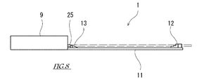
- FIG. 5 is a side view of the front guide 12
- FIG. FIG. 6 is a view taken along arrow VI-VI in FIG. 2.
- a pair of front guides 12 is provided at the tip of the blade 11.
- the front guide 12 is provided so as to protrude from one main surface (upper surface) of the blade 11. Since each front guide 12 has substantially the same structure, only one front guide 12 will be described below, and the other description will be omitted.
- the front guide 12 has a three-step shape in a side view as shown in detail in FIG.
- the front guide 12 has upper and lower two-stage support portions 12c and 12d.
- Each of the upper stage support part 12c and the lower stage support part 12d has an upward surface and can support the substrate 3 placed thereon.
- the front guide 12 has two upper and lower gripping portions 12a and 12b.
- Each of the upper stage gripping part 12 a and the lower stage gripping part 12 b has a surface facing the base end side of the blade 11.
- the upper stage support part 12c and the upper stage holding part 12a form a substantially right angle, and the edge of the substrate 3 placed on the upper stage support part 12c can come into contact with the upper stage holding part 12a.
- the lower support part 12d and the lower support part 12b form a substantially right angle, and the edge of the substrate 3 placed on the lower support part 12d can come into contact with the lower support part 12b.
- the height of the upper support portion 12c from the surface of the blade 11 is different from the height of the lower support portion 12d from the surface of the blade 11, and the upper support portion 12c is higher than the lower support portion 12d.
- the upper stage support part 12c is farther from the surface of the blade 11 than the lower stage support part 12d.
- the upper stage gripping part 12a is located closer to the tip side of the blade 11 than the lower stage gripping part 12b.
- the support parts 12c and 12d and the gripping parts 12a and 12b may be formed on one member, or may be formed on different members.
- a pair of lower rear guides 13 are provided on the base end side of the blade 11 so as to face the pair of front guides 12.
- the lower rear guide 13 has an upward support portion, and this support portion has a portion that matches the height of the lower support portion 12 d of the front guide 12.
- a pair of upper rear guides 130 are provided on the base end side of the blade 11 so as to face the pair of front guides 12.
- the upper rear guide 130 has an upward support portion, and this support portion has a portion that matches the height of the upper support portion 12 c of the front guide 12.
- the upper rear guide 130 is provided to be movable in the front-rear direction along the center line L4 of the blade 11.
- a cylinder 131 is provided as a driving device for the upper rear guide 130.
- a rod 132 extending parallel to the center line L4 is inserted into the cylinder 131 so as to be able to advance and retract.
- a rear guide support member 133 is connected to one end (output end) of the rod 132.
- An upper rear guide 130 is fixed to the rear guide support member 133.
- the upper rear guide 130 is in the casing 9 when it is most retracted, and is in front of the opening 9a of the casing 9 when it is most advanced.
- the opening 11 a is formed in the blade 11.
- the blade 11 is not present in the opening portion 11a, and an object passing through the opening portion 11a can be moved.
- the opening 11a is formed by cutting out the base end of the blade 11.
- the formation method of the opening part 11a is not limited to this.
- the opening 11a is provided over a range of the moving region of the upper rear guide 130 that overlaps the portion in front of the opening 9a of the casing 9 in the blade perpendicular direction. That is, the movement region of the upper rear guide 130 and the blade 11 do not overlap in the blade perpendicular direction.
- the operation of the upper rear guide 130 is controlled by the control device 8. More specifically, as shown in FIG. 4, an air supply device 18 such as a compressor is connected to the cylinder 131. A control valve 134 controlled by the control device 8 is provided between the air supply device 18 and the cylinder 131. The control device 8 switches the air flow rate and direction of the control valve 134 so that the rod 132 extends and the upper rear guide 130 moves forward, or the rod 132 contracts and the upper rear guide 130 moves backward.
- a lower pusher 25 that advances forward from the casing 9 and a cylinder 15 as a drive means for the lower pusher 25.
- a pusher 25 is connected to one end (output end) of the rod 16 of the cylinder 15.
- the lower pusher 25 has a pressing surface facing the tip side of the blade 11, and this pressing surface faces the lower grip portion 12 b of the front guide 12.
- the height of the pressing surface of the pusher 25 from the surface of the blade 11 is set so that the edge of the substrate 3 supported by the lower support portion 12d of the front guide 12 can be pressed. That is, the height of at least a part of the lower pusher 25 is set to coincide with the height of the substrate 3 supported by the lower support portion 12d of the front guide 12.
- the operation of the lower pusher 25 is controlled by the control device 8. More specifically, as shown in FIG. 4, an air supply device 18 such as a compressor is connected to the cylinder 15. A control valve 19 controlled by the control device 8 is provided between the air supply device 18 and the cylinder 15. The control device 8 switches the air flow rate and direction of the control valve 19 so that the rod 16 extends and the lower pusher 25 moves forward, or the rod 16 contracts and the lower pusher 25 moves backward.
- an air supply device 18 such as a compressor is connected to the cylinder 15.
- a control valve 19 controlled by the control device 8 is provided between the air supply device 18 and the cylinder 15. The control device 8 switches the air flow rate and direction of the control valve 19 so that the rod 16 extends and the lower pusher 25 moves forward, or the rod 16 contracts and the lower pusher 25 moves backward.
- the cylinder 15 is provided with a sensor (not shown) for detecting the position of the rod 16.
- the position of the lower pusher 25 can be obtained from the detected position of the rod 16.
- the control device 8 By processing information from this sensor by the control device 8, the presence or absence of the substrate 3 can be determined. That is, when the lower pusher 25 is moved forward from the casing 9 and the lower pusher 25 is held at a position where the predetermined pusher 3 is pressed, the control device 8 has the substrate 3 on the lower support portion 12d. It can be judged. On the other hand, the control device 8 can determine that there is no substrate 3 when the lower pusher 25 has passed the position where the predetermined substrate 3 is pressed.
- an upper pusher 250 that advances forward from the casing 9, and a cylinder 150 as a drive means for the upper pusher 250.
- An upper pusher 250 is connected to one end (output end) of the rod 160 of the cylinder 150.
- the upper pusher 250 has a pressing surface facing the tip side of the blade 11, and this pressing surface faces the upper gripping portion 12 a of the blade 11.
- the height of the pressing surface of the pusher 250 from the surface of the blade 11 is set so that the edge of the substrate 3 supported by the upper support portion 12c of the front guide 12 can be pressed. That is, the height of at least a part of the upper pusher 250 is set to coincide with the height of the substrate 3 supported by the upper support portion 12c.
- the operation of the upper pusher 250 is controlled by the control device 8. More specifically, as shown in FIG. 4, an air supply device 18 such as a compressor is connected to the cylinder 150. A control valve 190 controlled by the control device 8 is provided between the air supply device 18 and the cylinder 150. Then, when the control device 8 switches the flow rate and direction of the air of the control valve 190, the rod 160 extends and the upper pusher 250 moves forward, or the rod 160 contracts and the upper pusher 250 moves backward.
- an air supply device 18 such as a compressor is connected to the cylinder 150.
- a control valve 190 controlled by the control device 8 is provided between the air supply device 18 and the cylinder 150. Then, when the control device 8 switches the flow rate and direction of the air of the control valve 190, the rod 160 extends and the upper pusher 250 moves forward, or the rod 160 contracts and the upper pusher 250 moves backward.
- the cylinder 150 is provided with a sensor (not shown) that detects the position of the rod 160. From the detected position of the rod 160, the position of the upper pusher 250 can be obtained. By processing information from this sensor by the control device 8, the presence or absence of the substrate 3 can be determined. That is, the control device 8 can determine that the substrate 3 is present when the upper pusher 250 is in a position to push the predetermined substrate 3 in a state where the upper pusher 250 has advanced forward from the casing 9. On the other hand, the control device 8 can determine that there is no substrate 3 when the upper pusher 250 has passed the position where the predetermined substrate 3 is pressed.
- FIG. 6 is a view taken along the line VI-VI of the substrate transport hand 1 shown in FIG.
- elements other than the blade 11, the pushers 25 and 250, and the rear guides 13 and 130 are omitted.
- 6 indicates a substrate 3 (hereinafter referred to as “lower substrate 3L” when specifically distinguished) supported by the lower support portion 12d and the lower rear guide 13 of the front guide 12, and the front guide.
- 12 is a substrate 3 supported by an upper support portion 12c and an upper rear guide 130 (hereinafter referred to as “upper substrate 3U” when particularly distinguished).
- the position of the rear guide support member 133 in the blade perpendicular direction and the position of the blade 11 in the blade perpendicular direction partially overlap each other.
- the lowermost surface of the rear guide support member 133 is lower than the uppermost surface of the blade 11.
- the thickness of the rear guide support member 133 can be increased, and the deformation amount of the rear guide support member 133 when the upper rear guide 130 supports the substrate 3 can be reduced.
- the lowermost surface of the upper rear guide 130 is lower than the uppermost surface of the blade 11.
- the lower pusher 25 and the upper pusher 250 are configured differently in the VI-VI arrow view.
- the lower pusher 25 may have a height that does not overlap the upper substrate 3U, and the upper pusher 250 may have a height that does not overlap the lower substrate 3L. By doing so, the lower pusher 25 does not interfere with the upper substrate 3U, and the lower pusher 25 does not interfere with the lower substrate 3L.
- the lower pusher 25 may have a height that overlaps with the upper substrate 3U, and the upper pusher 250 may have a height that overlaps with the lower substrate 3L.
- the stroke of the pushers 25 and 250 means the movement range of the pushers 25 and 250, and is defined by the most backward movement position and the most forward movement position of the pushers 25 and 250.
- the lower support portion 12d of the pair of front guides 12 and the substrate 3 (3L) supported by the lower rear guide 13 are indicated by alternate long and short dash lines.
- This substrate 3 is, for example, a contaminated substrate 3.
- the upper rear guide 130, the lower pusher 25 and the upper pusher 250 are retracted from the substrate 3, and these do not interfere with the substrate 3.
- the lower pusher 25 moves forward from this state, the substrate 3 supported by the lower support portion 12d and the lower rear guide 13 of the front guide 12 is pushed forward by the lower pusher 25.
- the front edge of the substrate 3 comes into contact with the pair of lower gripping portions 12b. In this way, the substrate 3 is gripped by the substrate transport hand 1 by pressing the edge of the substrate 3 from three points of the pair of lower gripping portions 12b and the lower pusher 25 (see FIGS. 7 and 8). .
- the control device 8 monitors a detection signal from a sensor (not shown) for detecting the position of the lower pusher 25 after the lower pusher 25 starts moving forward. 7 and 8, the lower pusher 25 is in a position to push the predetermined substrate 3, so the control device 8 determines that the lower substrate 3 (3 ⁇ / b> L) is on the blade 11.
- the upper support 12c of the pair of front guides 12 and the substrate 3 (3U) supported by the upper rear guide 130 are indicated by alternate long and short dash lines.
- This substrate 3 is, for example, a clean substrate 3.
- the upper rear guide 130 has been advanced to a position where the substrate 3 can be supported.
- the lower pusher 25 and the upper pusher 250 are retracted from the edge of the substrate 3 and do not interfere with the substrate 3.
- the upper pusher 250 moves forward from this state, the substrate 3 supported by the upper support portion 12 c and the upper rear guide 130 of the front guide 12 is pushed forward by the upper pusher 250.
- the front edge of the substrate 3 comes into contact with the pair of upper gripping portions 12a. In this way, the substrate 3 is gripped by the substrate transport hand 1 by pressing the edge of the substrate 3 from three points of the pair of upper gripping portions 12a and the upper pusher 250 (see FIGS. 11 and 12). .
- the control device 8 monitors a detection signal from a sensor (not shown) for detecting the position of the upper pusher 250 after the upper pusher 250 starts moving forward. In the state shown in FIGS. 11 and 12, the upper pusher 250 is in a position to press the predetermined substrate 3, and therefore the control device 8 determines that the upper substrate 3 (3 U) is on the blade 11.
- the contaminated substrate 3 is supported by the lower support portion 12d and the lower rear guide 13 of the pair of front guides 12, and is gripped by the lower grip portion 12b and the lower pusher 25 of the pair of front guides 12.
- the clean substrate 3 is supported by the upper support portion 12 c and the upper rear guide 130 of the pair of front guides 12 and is gripped by the upper grip portion 12 a and the upper pusher 250 of the pair of front guides 12.
- the substrate transfer hand 1 is contaminated by the contaminated substrate 3 by properly using the support portion and the gripping portion for the contaminated substrate and the clean substrate, and the clean substrate held by the substrate transfer hand 1 is used. 3 can be prevented from being contaminated.
- the clean substrate and the contaminated substrate are held at different heights on the substrate transport hand 1, it is desirable to hold the clean substrate at a high position. This is because the pollutant falls from the top to the bottom due to an air flow called downflow for maintaining a clean environment.
- FIG. 13 is a diagram illustrating the stroke of the lower pusher 25 and the stroke of the upper pusher 250.
- the stroke of the lower pusher 25 depends on the advance / retreat distance of the rod 16 of the cylinder 15, the relationship between the position of the substrate 3 held by the substrate transport hand 1 and the mounting position of the cylinder 15, and the lower pusher 25 provided as necessary. It is adjusted depending on the attachment position of a stopper (not shown) for adjusting the stroke, the attachment position of the lower pusher 25 with respect to the rod 16, and the like.
- the stroke of the upper pusher 250 is determined by the advance / retreat distance of the rod 160 of the cylinder 150, the relationship between the position of the substrate 3 held by the substrate transport hand 1 and the mounting position of the cylinder 150, and the upper pusher provided as necessary. It is adjusted depending on the mounting position of a stopper (not shown) for adjusting the stroke of 250, the mounting position of the upper pusher 250 with respect to the rod 160, and the like.
- a position 25a is a state where the lower pusher 25 is most retracted
- a position 25b is a state where the lower substrate 3L is on the blade 11, and the lower pusher 25 is pushing the lower substrate 3L
- a position 25c is The position of 25 points in each state in which the lower substrate 3L is not on the blade 11 and the pusher 25 is most advanced is shown.
- a position 250a is a state in which the upper pusher 250 is most retracted
- a position 250b is a state in which the upper substrate 3U is on the blade 11, and the upper pusher 250 is pressing the upper substrate 3U
- 250c shows the position of 250 points in each state where the upper substrate 3U is not on the blade 11 and the upper pusher 250 is most advanced.
- the stroke of the lower pusher 25 is set so that the lower pusher 25 is located behind the upper substrate 3U in a state where 25point is at the position 25c.
- the stroke of the lower pusher 25 is in front of the two substrates 3 that are held by the substrate transfer hand 1 while being shifted from each other in the front-rear direction (and the up-down direction) with the lower-stage pusher 25 moving forward most.
- the substrate 3 and the lower pusher 25 are set so as not to interfere with each other. In this way, regardless of the position of the lower pusher 25, it is possible to avoid the interference between the lower pusher 25 and the substrate 3 that is shifted forward among the two substrates 3 that are held shifted in the front-rear direction. .
- the stroke of the upper pusher 250 is set so that the upper pusher 250 is located behind the lower substrate 3L when 250 points are at the position 250a.
- the stroke of the upper pusher 250 is behind the two substrates 3 that are held by the substrate transfer hand 1 while being shifted from each other in the front-rear direction (and the vertical direction) with the upper-stage pusher 250 retracted most.
- the substrate 3 and the upper pusher 250 are set so as not to interfere with each other. In this way, if the upper pusher 250 is moved most backward, interference between the rear substrate 3 and the upper pusher 250 out of the two substrates 3 that are held while being shifted in the front-rear direction can be avoided. .
- the substrate transport hand 1 includes the casing 9, the thin blade 11 having the base end coupled to the casing 9, and the tip of the blade 11. 11, a front guide 12 having a lower support portion (first support portion) 12 d and an upper support portion (second support portion) 12 c having different heights from the substrate 11, and a base end portion of the blade 11.
- a lower rear guide (first rear guide) 13 having a portion where the lower support portion 12d of the guide 12 and the height from the blade 11 coincide with each other, and an upper support portion 12c of the front guide 12 provided on the base end side of the blade 11.
- an upper rear guide (second rear guide) 130 having a portion whose height from the blade 11 coincides with each other, and is provided in the casing 9 and supported by the blade 11.
- An output terminal for forward and backward movement relative to the plate, and a cylinder (driving device) 131 which moves in a region which does not overlap the upper rear guide 130 coupled with the output end to the blade 11 and the blade perpendicular direction.
- the transfer robot 2 includes an arm 40 and a substrate transfer hand 1 attached to the tip of the arm 40.
- the upper rear guide 130 provided on the base end side of the substrate transport hand 1 moves forward and backward with respect to the substrate 3 supported by the blade 11.
- a certain cylinder 131 is accommodated in the casing 9. That is, the upper rear guide 130 and its driving device are arranged together at the base end of the substrate transport hand 1. Since the upper rear guide 130 moves in a region that does not overlap the blade 11 and the vertical direction of the blade, the upper rear guide 130 and its driving device can be provided avoiding the blade 11. Therefore, a reduction in the strength of the blade 11 due to the provision of the upper rear guide 130 and the cylinder 131 which is a driving device thereof is avoided. That is, the blade 11 has an appropriate strength, and the stability of the operation of the substrate transport hand 1 is not impaired.
- the height of the lower support portion (first support portion) 12d from the blade 11 is lower than the height of the upper support portion (second support portion) 12c from the blade 11. .
- the lower support portion 12d being lower than the upper support portion 12c means that the lower rear guide 13 is lower than the upper rear guide 130.
- the upper rear guide 130 can be retracted from the substrate 3 when the substrate 3 is supported by the cooperation of the lower rear guide 13 and the lower support portion 12d. That is, the upper rear guide 130 can be kept away from the contamination source. Since the pollutant falls from the top to the bottom, if the rear guide (upper rear guide 130) that can be moved away from the pollution source is placed on the top and the other on the bottom, the rear guide (upper rear guide 130) placed on the top Cleanliness can be further improved.
- the contaminated substrate 3 is supported by the combination of the lower rear guide 13 and the lower support portion 12d, and the clean substrate 3 is combined by the combination of the upper rear guide 130 and the upper support portion 12c. It is good to support.
- FIGS. 14 is an enlarged plan view of the substrate transfer hand 1A according to the first modification
- FIG. 15 is a view taken along the arrow XV-XV in FIG. 14,
- FIG. 16 shows a state in which the substrate transfer hand 1A in FIG.
- FIG. 17 is a plan view showing a state in which the substrate transport hand 1A of FIG. 14 grips the upper substrate 3U.
- the same or similar members as those in the above-described embodiment may be denoted by the same reference numerals in the drawings, and description thereof may be omitted.
- the substrate transport hand 1A according to Modification 1 is different from the substrate transport hand 1 according to the above embodiment in the configuration of the lower pusher 25 and the upper pusher 250, and the other configurations are substantially the same. Therefore, in the following, the configurations of the lower pusher 25A and the upper pusher 250A of the substrate transport hand 1A according to Modification 1 will be described in detail, and the description of the remaining configuration will be omitted.
- a pair of lower pushers 25 ⁇ / b> A is provided on the base end side of the blade 11.
- the pair of lower pushers 25 ⁇ / b> A are arranged symmetrically via the center line L ⁇ b> 4 of the blade 11.
- the pair of lower pushers 25 ⁇ / b> A are attached to both ends of a pusher support member 111 extending in an arc shape in a direction orthogonal to the center line L ⁇ b> 4 of the blade 11.
- the central portion of the pusher support member 111 is connected to the tip portion of the rod 16.
- a pair of upper pushers 250A are provided on the base end side of the blade 11.
- the pair of upper pushers 250 ⁇ / b> A are arranged symmetrically via the center line L ⁇ b> 4 of the blade 11.
- the pair of upper pushers 250A are attached to both ends of the pusher support member 110 extending in an arc shape in a direction orthogonal to the center line L4 of the blade 11.
- the central portion of the pusher support member 110 is connected to the tip portion of the rod 160.
- the distance from the upper pusher 250A to the center line L4 of the blade 11 is smaller than the distance from the lower pusher 25A to the center line L4 of the blade 11. That is, the pair of upper pushers 250A is arranged inside the pair of lower pushers 25A when the center line L4 is the center. Further, the distance from these pushers 25A, 250A to the center line L4 of the blade 11 is larger than the distance from the rear guides 13, 130 to the center line L4 of the blade 11. In other words, the pushers 25A and 250A are disposed outside the rear guides 13 and 130 when the center line L4 is the center.
- the pusher support member 111 and the pusher support member 110 are disposed higher than the lower rear guide 13 and the upper rear guide 130 from the surface of the blade 11.
- the pair of lower pushers 25 ⁇ / b> A is attached to the pusher support member 111 so as to hang down from the pusher support member 111.
- the pair of lower pushers 25 ⁇ / b> A has a pressing surface facing the tip side of the blade 11, and the pressing surfaces are at the same level as and opposed to the lower holding portion 12 b of the front guide 12.
- the pair of upper pushers 250 ⁇ / b> A is attached to the pusher support member 110 so as to hang down from the pusher support member 110.
- the pair of upper pushers 250 ⁇ / b> A has a pressing surface facing the tip side of the blade 11, and the pressing surfaces are at the same level as the upper gripping portion 12 a of the blade 11 and face each other. Note that these pushers 25 ⁇ / b> A and 250 ⁇ / b> A are arranged at a position higher than the bottom surface of the blade 11. In this way, when another substrate transfer hand 1 (not shown) is provided under the substrate transfer hand 1A to form a so-called double-handed transfer robot 2, the two substrate transfer hands 1 Interference can be prevented.
- the substrate 3 can be pressed more stably by pressing the edge of the substrate 3 in two places by the pusher 25A or 250A. Further, since the pusher support members 111 and 110 are elongated members, when the substrate 3 is pushed by the pushers 25A and 250A, the pusher support members 111 and 110 are elastically deformed so that the substrate 3 can be gripped more flexibly. .
- FIGS. 18 is an enlarged plan view of the substrate transport hand 1B according to the second modification
- FIG. 19 is a view taken along the arrow XIX-XIX in FIG. 18,
- FIG. 20 shows a state in which the substrate transport hand 1B in FIG. FIG.
- the same or similar members as those in the above-described embodiment may be denoted by the same reference numerals in the drawings, and description thereof may be omitted.
- the substrate transport hand 1B according to Modification 2 is different from the substrate transport hand 1 according to the above embodiment in the arrangement and configuration of the upper rear guide 130 and the rear guide support member 133, and the remaining configuration is substantially the same. Are the same. Therefore, hereinafter, the configurations of the upper rear guide 130B and the rear guide support member 133B of the substrate transport hand 1B according to Modification 2 will be described in detail, and the description of the remaining configurations will be omitted.
- the pair of upper rear guides 130 is disposed inside the pair of lower rear guides 13 when the center line L4 of the blade 11 is set at the center.
- the pair of upper rear guides 130B is disposed outside the pair of lower rear guides 13 when the center line L4 of the blade 11 is the center.
- the pair of upper rear guides 130 ⁇ / b> B are disposed outside the blade 11.
- a rear guide support member 133B is provided between the rod 132 of the cylinder 131 and the upper rear guide 130.
- the rear guide support member 133B is a member for taking out the upper rear guide 130 to a region (here, both sides of the blade 11) that does not overlap the blade 11 and the vertical direction of the blade.
- the rear guide support member 133B includes a first member 200 extending in a direction orthogonal to the center line L4 of the hand body, and a second member 201 coupled to both ends of the first member 200.
- the first member 200 extends to the outside of the blade 11 on both sides across the center line L4 of the hand body. Further, the first member 200 is connected to the rod 132 so as to be higher than the lower pusher 25, the upper pusher 250, and the lower rear guide 13.
- the second member 201 is formed in an L shape by a vertical portion joined to the first member 200 and a horizontal portion to which the upper rear guide 130B is attached.
- the upper rear guide 130B attached to the second member 201 has an upward support portion, and this support portion has a portion that coincides with the height of the upper support portion 12c of the front guide 12.
- the position in the blade normal direction of at least a portion of the second member 201 of the upper rear guide 130B or the rear guide support member 133B and the position in the blade normal direction of the blade 11 may overlap. That is, at least a part of the second member 201 of the upper rear guide 130B or the rear guide support member 133B and the blade 11 may be at the same level. In this way, the thickness of the substrate transport hand 1 including the rear guide support member 133B can be suppressed, and is particularly useful when the substrate transport hand 1 includes a plurality of hands.
- the upper rear guide 130B having the above configuration moves forward and backward along the center line L4 of the blade 11.
- the upper rear guide 130B and the rear guide support member 133B move within a range that does not overlap the blade 11 and the blade perpendicular direction.
- the operation of the upper rear guide 130B is realized by the action of the cylinder 131 controlled by the control device 8 as in the above-described embodiment.
- the blade 11 has a Y-shape as viewed from the direction of the blade normal, but the blade 11 does not have to be divided into two forks.
- the blade 11 may be composed of a plurality of members.
- the upper rear guide 130 and the rear guide support member 133 are separate members.
- the upper rear guide 130 and the rear guide support member 133 may be integrally formed.
- another element may be interposed between the upper rear guide 130 and the rear guide support member 133.
- the upper rear guide 130 may be provided directly on the rod 132 of the cylinder 131. In short, it is sufficient that the movement of the rod 132 of the air cylinder 131 is transmitted to the upper rear guide 130 and the rear guide 130 is disposed at an appropriate position.
- the pushers 25A and 250A and the pusher support members 111 and 110 are separate members. However, the pushers 25A and 250A and the pusher support members 111 and 110 may be integrally configured. Further, other elements may be interposed between the pushers 25A and 250A and the pusher support members 111 and 110. In short, the movement of the rods 16 and 160 of the air cylinders 15 and 150 may be transmitted to the pushers 25A and 250A, and the pushers 25A and 250A may be arranged at appropriate positions.
- the pushers 25 and 250 and the rear guide 130 may be moved by a moving means other than the cylinder and the rod.
- the moving direction of the output end of the moving means for moving the pushers 25, 250 and the rear guide 130 is not limited to the front-rear direction of the blade 11, and any direction can be used as long as it can move forward and backward with respect to the substrate 3 supported by the blade 11. Such a direction may be used.
- the movement path of the output end of the moving means for moving the pushers 25 and 250 and the rear guide 130 is not limited to a straight line, and may be a circle, a curve, or a combination thereof.
- Substrate transport hand 2 Transport robot 3, 3L, 3U: Substrate 8: Control device 9: Casing 11: Blade 11a: Opening portion 12: Front guide 12a: Upper gripping portion 12b: Lower gripping portion 12c: Upper support 12d: Lower support 13: Lower rear guide 15: Cylinder 16: Rod 18: Air supply device 19: Control valve 25, 25A: Lower pusher 110: Pusher support member 111: Pusher support member 130: Upper rear guide 131 : Cylinder (drive device) 132: Rod 133, 133B: Rear guide support member 150: Cylinder 160: Rod 250, 250A: Upper pusher
Priority Applications (3)
| Application Number | Priority Date | Filing Date | Title |
|---|---|---|---|
| KR1020187029335A KR20180127400A (ko) | 2016-03-25 | 2017-03-01 | 기판 반송 핸드 및 로봇 |
| CN201780018545.7A CN108780771A (zh) | 2016-03-25 | 2017-03-01 | 基板搬送手及机器人 |
| US16/088,389 US20190148210A1 (en) | 2016-03-25 | 2017-03-01 | Substrate transfer hand and robot |
Applications Claiming Priority (2)
| Application Number | Priority Date | Filing Date | Title |
|---|---|---|---|
| JP2016-062130 | 2016-03-25 | ||
| JP2016062130A JP2017175072A (ja) | 2016-03-25 | 2016-03-25 | 基板搬送ハンド及びロボット |
Publications (1)
| Publication Number | Publication Date |
|---|---|
| WO2017163796A1 true WO2017163796A1 (ja) | 2017-09-28 |
Family
ID=59901081
Family Applications (1)
| Application Number | Title | Priority Date | Filing Date |
|---|---|---|---|
| PCT/JP2017/008143 WO2017163796A1 (ja) | 2016-03-25 | 2017-03-01 | 基板搬送ハンド及びロボット |
Country Status (6)
| Country | Link |
|---|---|
| US (1) | US20190148210A1 (zh) |
| JP (1) | JP2017175072A (zh) |
| KR (1) | KR20180127400A (zh) |
| CN (1) | CN108780771A (zh) |
| TW (1) | TWI631648B (zh) |
| WO (1) | WO2017163796A1 (zh) |
Cited By (1)
| Publication number | Priority date | Publication date | Assignee | Title |
|---|---|---|---|---|
| WO2022049783A1 (ja) * | 2020-09-03 | 2022-03-10 | 川崎重工業株式会社 | 基板保持ハンドおよび基板搬送ロボット |
Families Citing this family (6)
| Publication number | Priority date | Publication date | Assignee | Title |
|---|---|---|---|---|
| JP6604890B2 (ja) * | 2016-04-04 | 2019-11-13 | 株式会社荏原製作所 | 基板搬送装置および基板処理装置ならびに結露抑制方法 |
| CN111319047A (zh) * | 2018-12-13 | 2020-06-23 | 上海新昇半导体科技有限公司 | 一种晶圆夹持机械手臂组件 |
| JP2021136397A (ja) * | 2020-02-28 | 2021-09-13 | 川崎重工業株式会社 | 基板保持ハンド及び基板移送ロボット |
| CN111348427B (zh) * | 2020-03-13 | 2022-04-22 | 北京北方华创微电子装备有限公司 | 机械手 |
| TWI746240B (zh) * | 2020-09-03 | 2021-11-11 | 日商川崎重工業股份有限公司 | 基板保持手及基板搬送機器人 |
| JP7420954B2 (ja) | 2020-09-03 | 2024-01-23 | 川崎重工業株式会社 | 基板保持ハンドおよび基板搬送ロボット |
Citations (5)
| Publication number | Priority date | Publication date | Assignee | Title |
|---|---|---|---|---|
| JP2007067345A (ja) * | 2005-09-02 | 2007-03-15 | Hirata Corp | 枚葉式ワーク把持装置 |
| JP2011228625A (ja) * | 2010-03-31 | 2011-11-10 | Yaskawa Electric Corp | 基板搬送用ハンドおよび基板搬送ロボット |
| JP2013006222A (ja) * | 2009-10-14 | 2013-01-10 | Rorze Corp | 薄板状物の把持装置、および薄板状物の把持方法 |
| WO2014103300A1 (ja) * | 2012-12-27 | 2014-07-03 | 川崎重工業株式会社 | エンドエフェクタ装置 |
| WO2015098153A1 (ja) * | 2013-12-26 | 2015-07-02 | 川崎重工業株式会社 | エンドエフェクタおよび基板搬送ロボット |
Family Cites Families (6)
| Publication number | Priority date | Publication date | Assignee | Title |
|---|---|---|---|---|
| US7611182B2 (en) * | 2005-02-25 | 2009-11-03 | Semes Co., Ltd. | Wafer transfer apparatus |
| US20080213076A1 (en) * | 2007-03-02 | 2008-09-04 | Stephen Hanson | Edge grip end effector |
| JP5491834B2 (ja) * | 2009-12-01 | 2014-05-14 | 川崎重工業株式会社 | エッジグリップ装置、及びそれを備えるロボット。 |
| WO2012176060A1 (en) * | 2011-06-23 | 2012-12-27 | Dynamic Micro Systems | Semiconductor cleaner systems and methods |
| US9343341B2 (en) * | 2011-08-10 | 2016-05-17 | Kawasaki Jukogyo Kabushiki Kaisha | End effector device and substrate conveying robot including end effector device |
| JP6009832B2 (ja) * | 2012-06-18 | 2016-10-19 | 株式会社Screenホールディングス | 基板処理装置 |
-
2016
- 2016-03-25 JP JP2016062130A patent/JP2017175072A/ja active Pending
-
2017
- 2017-02-23 TW TW106106143A patent/TWI631648B/zh active
- 2017-03-01 WO PCT/JP2017/008143 patent/WO2017163796A1/ja active Application Filing
- 2017-03-01 KR KR1020187029335A patent/KR20180127400A/ko not_active Application Discontinuation
- 2017-03-01 CN CN201780018545.7A patent/CN108780771A/zh active Pending
- 2017-03-01 US US16/088,389 patent/US20190148210A1/en not_active Abandoned
Patent Citations (5)
| Publication number | Priority date | Publication date | Assignee | Title |
|---|---|---|---|---|
| JP2007067345A (ja) * | 2005-09-02 | 2007-03-15 | Hirata Corp | 枚葉式ワーク把持装置 |
| JP2013006222A (ja) * | 2009-10-14 | 2013-01-10 | Rorze Corp | 薄板状物の把持装置、および薄板状物の把持方法 |
| JP2011228625A (ja) * | 2010-03-31 | 2011-11-10 | Yaskawa Electric Corp | 基板搬送用ハンドおよび基板搬送ロボット |
| WO2014103300A1 (ja) * | 2012-12-27 | 2014-07-03 | 川崎重工業株式会社 | エンドエフェクタ装置 |
| WO2015098153A1 (ja) * | 2013-12-26 | 2015-07-02 | 川崎重工業株式会社 | エンドエフェクタおよび基板搬送ロボット |
Cited By (2)
| Publication number | Priority date | Publication date | Assignee | Title |
|---|---|---|---|---|
| WO2022049783A1 (ja) * | 2020-09-03 | 2022-03-10 | 川崎重工業株式会社 | 基板保持ハンドおよび基板搬送ロボット |
| JP7459265B2 (ja) | 2020-09-03 | 2024-04-01 | 川崎重工業株式会社 | 基板保持ハンドおよび基板搬送ロボット |
Also Published As
| Publication number | Publication date |
|---|---|
| TW201742178A (zh) | 2017-12-01 |
| TWI631648B (zh) | 2018-08-01 |
| JP2017175072A (ja) | 2017-09-28 |
| KR20180127400A (ko) | 2018-11-28 |
| CN108780771A (zh) | 2018-11-09 |
| US20190148210A1 (en) | 2019-05-16 |
Similar Documents
| Publication | Publication Date | Title |
|---|---|---|
| WO2017163796A1 (ja) | 基板搬送ハンド及びロボット | |
| CN107534007B (zh) | 衬底搬送机器人及衬底处理系统 | |
| CN108028218B (zh) | 衬底搬送机器人及衬底处理系统 | |
| US10283395B2 (en) | Substrate gripping hand and substrate transfer apparatus | |
| CN107275268B (zh) | 机械手单元及移载方法 | |
| CN110249420B (zh) | 基板把持手及基板搬运装置 | |
| WO2016175133A1 (ja) | 基板搬送ロボットおよび基板検出方法 | |
| TW201043417A (en) | Robot having end effector and method of operating the same | |
| KR102298468B1 (ko) | 스크라이브 장치 | |
| JP2009065165A (ja) | エンドエフェクタ及びこれを有する基板移送ロボット | |
| JP2002134586A (ja) | 基板保持装置 | |
| KR101495962B1 (ko) | 로봇 시스템 | |
| TWI656003B (zh) | Substrate transfer system and method | |
| JP2011125967A (ja) | ウェーハ搬送ロボット用のハンド、ウェーハ搬送ロボット及びウェーハ搬送装置 | |
| CN112740394A (zh) | 晶片分割装置、翻转装置以及搬运系统 | |
| JP2006327819A (ja) | ガラス板の移載装置および移載方法 | |
| KR101285988B1 (ko) | 프리얼라이너 장치 | |
| JP2009160711A (ja) | エンドエフェクタ及びそれを備えた搬送装置 | |
| US6343905B1 (en) | Edge gripped substrate lift mechanism | |
| JP6116088B2 (ja) | エンドエフェクタ装置及び該エンドエフェクタ装置を用いた板状部材の位置決め方法 | |
| JP5479948B2 (ja) | 搬送機構 | |
| JP3760212B2 (ja) | アライメント処理方法およびアライメント処理装置 | |
| JPH1111662A (ja) | 基板の移載装置及び移載方法 | |
| JP2012135874A (ja) | エンドエフェクタ及びそれを備えた搬送装置 |
Legal Events
| Date | Code | Title | Description |
|---|---|---|---|
| NENP | Non-entry into the national phase |
Ref country code: DE |
|
| ENP | Entry into the national phase |
Ref document number: 20187029335 Country of ref document: KR Kind code of ref document: A |
|
| 121 | Ep: the epo has been informed by wipo that ep was designated in this application |
Ref document number: 17769841 Country of ref document: EP Kind code of ref document: A1 |
|
| 122 | Ep: pct application non-entry in european phase |
Ref document number: 17769841 Country of ref document: EP Kind code of ref document: A1 |