WO2017163796A1 - 基板搬送ハンド及びロボット - Google Patents
基板搬送ハンド及びロボット Download PDFInfo
- Publication number
- WO2017163796A1 WO2017163796A1 PCT/JP2017/008143 JP2017008143W WO2017163796A1 WO 2017163796 A1 WO2017163796 A1 WO 2017163796A1 JP 2017008143 W JP2017008143 W JP 2017008143W WO 2017163796 A1 WO2017163796 A1 WO 2017163796A1
- Authority
- WO
- WIPO (PCT)
- Prior art keywords
- blade
- substrate
- rear guide
- pusher
- hand
- Prior art date
Links
Images


Classifications
-
- H—ELECTRICITY
- H01—ELECTRIC ELEMENTS
- H01L—SEMICONDUCTOR DEVICES NOT COVERED BY CLASS H10
- H01L21/00—Processes or apparatus adapted for the manufacture or treatment of semiconductor or solid state devices or of parts thereof
- H01L21/67—Apparatus specially adapted for handling semiconductor or electric solid state devices during manufacture or treatment thereof; Apparatus specially adapted for handling wafers during manufacture or treatment of semiconductor or electric solid state devices or components ; Apparatus not specifically provided for elsewhere
- H01L21/677—Apparatus specially adapted for handling semiconductor or electric solid state devices during manufacture or treatment thereof; Apparatus specially adapted for handling wafers during manufacture or treatment of semiconductor or electric solid state devices or components ; Apparatus not specifically provided for elsewhere for conveying, e.g. between different workstations
- H01L21/67739—Apparatus specially adapted for handling semiconductor or electric solid state devices during manufacture or treatment thereof; Apparatus specially adapted for handling wafers during manufacture or treatment of semiconductor or electric solid state devices or components ; Apparatus not specifically provided for elsewhere for conveying, e.g. between different workstations into and out of processing chamber
- H01L21/67742—Mechanical parts of transfer devices
-
- B—PERFORMING OPERATIONS; TRANSPORTING
- B25—HAND TOOLS; PORTABLE POWER-DRIVEN TOOLS; MANIPULATORS
- B25J—MANIPULATORS; CHAMBERS PROVIDED WITH MANIPULATION DEVICES
- B25J11/00—Manipulators not otherwise provided for
- B25J11/0095—Manipulators transporting wafers
-
- B—PERFORMING OPERATIONS; TRANSPORTING
- B25—HAND TOOLS; PORTABLE POWER-DRIVEN TOOLS; MANIPULATORS
- B25J—MANIPULATORS; CHAMBERS PROVIDED WITH MANIPULATION DEVICES
- B25J15/00—Gripping heads and other end effectors
- B25J15/0014—Gripping heads and other end effectors having fork, comb or plate shaped means for engaging the lower surface on a object to be transported
-
- B—PERFORMING OPERATIONS; TRANSPORTING
- B25—HAND TOOLS; PORTABLE POWER-DRIVEN TOOLS; MANIPULATORS
- B25J—MANIPULATORS; CHAMBERS PROVIDED WITH MANIPULATION DEVICES
- B25J15/00—Gripping heads and other end effectors
- B25J15/0033—Gripping heads and other end effectors with gripping surfaces having special shapes
-
- B—PERFORMING OPERATIONS; TRANSPORTING
- B25—HAND TOOLS; PORTABLE POWER-DRIVEN TOOLS; MANIPULATORS
- B25J—MANIPULATORS; CHAMBERS PROVIDED WITH MANIPULATION DEVICES
- B25J15/00—Gripping heads and other end effectors
- B25J15/0052—Gripping heads and other end effectors multiple gripper units or multiple end effectors
- B25J15/0061—Gripping heads and other end effectors multiple gripper units or multiple end effectors mounted on a modular gripping structure
-
- B—PERFORMING OPERATIONS; TRANSPORTING
- B65—CONVEYING; PACKING; STORING; HANDLING THIN OR FILAMENTARY MATERIAL
- B65G—TRANSPORT OR STORAGE DEVICES, e.g. CONVEYORS FOR LOADING OR TIPPING, SHOP CONVEYOR SYSTEMS OR PNEUMATIC TUBE CONVEYORS
- B65G49/00—Conveying systems characterised by their application for specified purposes not otherwise provided for
- B65G49/05—Conveying systems characterised by their application for specified purposes not otherwise provided for for fragile or damageable materials or articles
- B65G49/07—Conveying systems characterised by their application for specified purposes not otherwise provided for for fragile or damageable materials or articles for semiconductor wafers Not used, see H01L21/677
-
- H—ELECTRICITY
- H01—ELECTRIC ELEMENTS
- H01L—SEMICONDUCTOR DEVICES NOT COVERED BY CLASS H10
- H01L21/00—Processes or apparatus adapted for the manufacture or treatment of semiconductor or solid state devices or of parts thereof
- H01L21/67—Apparatus specially adapted for handling semiconductor or electric solid state devices during manufacture or treatment thereof; Apparatus specially adapted for handling wafers during manufacture or treatment of semiconductor or electric solid state devices or components ; Apparatus not specifically provided for elsewhere
- H01L21/677—Apparatus specially adapted for handling semiconductor or electric solid state devices during manufacture or treatment thereof; Apparatus specially adapted for handling wafers during manufacture or treatment of semiconductor or electric solid state devices or components ; Apparatus not specifically provided for elsewhere for conveying, e.g. between different workstations
- H01L21/67763—Apparatus specially adapted for handling semiconductor or electric solid state devices during manufacture or treatment thereof; Apparatus specially adapted for handling wafers during manufacture or treatment of semiconductor or electric solid state devices or components ; Apparatus not specifically provided for elsewhere for conveying, e.g. between different workstations the wafers being stored in a carrier, involving loading and unloading
- H01L21/67766—Mechanical parts of transfer devices
-
- H—ELECTRICITY
- H01—ELECTRIC ELEMENTS
- H01L—SEMICONDUCTOR DEVICES NOT COVERED BY CLASS H10
- H01L21/00—Processes or apparatus adapted for the manufacture or treatment of semiconductor or solid state devices or of parts thereof
- H01L21/67—Apparatus specially adapted for handling semiconductor or electric solid state devices during manufacture or treatment thereof; Apparatus specially adapted for handling wafers during manufacture or treatment of semiconductor or electric solid state devices or components ; Apparatus not specifically provided for elsewhere
- H01L21/683—Apparatus specially adapted for handling semiconductor or electric solid state devices during manufacture or treatment thereof; Apparatus specially adapted for handling wafers during manufacture or treatment of semiconductor or electric solid state devices or components ; Apparatus not specifically provided for elsewhere for supporting or gripping
- H01L21/687—Apparatus specially adapted for handling semiconductor or electric solid state devices during manufacture or treatment thereof; Apparatus specially adapted for handling wafers during manufacture or treatment of semiconductor or electric solid state devices or components ; Apparatus not specifically provided for elsewhere for supporting or gripping using mechanical means, e.g. chucks, clamps or pinches
- H01L21/68707—Apparatus specially adapted for handling semiconductor or electric solid state devices during manufacture or treatment thereof; Apparatus specially adapted for handling wafers during manufacture or treatment of semiconductor or electric solid state devices or components ; Apparatus not specifically provided for elsewhere for supporting or gripping using mechanical means, e.g. chucks, clamps or pinches the wafers being placed on a robot blade, or gripped by a gripper for conveyance
Definitions
- the present invention relates to a substrate transfer hand for holding and transferring a substrate such as a semiconductor wafer or a glass substrate, and a robot including the same.
- a transfer robot for transferring a substrate such as a semiconductor wafer or a glass substrate has an end effector, for example, a hand at its tip, and is configured to hold and transfer the substrate by this hand.
- An example of a hand that holds a substrate is an edge grip hand that holds a substrate.
- Patent Document 1 describes a hand having two sets of a plurality of claws for holding a substrate (see FIG. 10 and the like). In the hand described in Patent Document 1, one set of claws is used for a contaminated substrate, and the other set of claws is used for a clean substrate, thereby preventing the substrate from being contaminated as described above.
- Patent Literature 1 the two sets of claws are configured such that the substrate held by one set of claws is slightly higher than the substrate held by the other set of claws. ing. It is an object of Patent Document 1 to provide a thin and compact single-wafer workpiece gripping device by configuring the hand in this way.
- a metal belt extending from the blade proximal end side to the blade distal end side is used as a power transmission member for sliding a claw provided at the distal end portion of the blade.
- the strength of the blade is lowered by the hollow portion.
- the blade is a thin plate-like member, and if the bending easily occurs due to a decrease in strength, the stability of the operation of the hand may be impaired.
- an object of the present invention is to provide a substrate transport hand provided with a plurality of sets of substrate support portions on one blade, which realizes a stable operation, and a robot including the substrate transport hand. Yes.
- the substrate transport hand is A casing, A thin blade having a base end coupled to the casing; A front guide having a first support portion and a second support portion of a substrate provided at a tip portion of the blade and having different heights from the blade; A first rear guide provided at a base end portion of the blade and having a portion whose height from the blade coincides with the first support portion of the front guide; A second rear guide provided on the base end side of the blade, and having a portion where the height of the front support and the second support portion of the front guide coincide with each other; The second rear guide, which is provided in the casing and has an output end that moves forward and backward with respect to the substrate supported by the blade, and is coupled to the output end does not overlap the vertical direction of the blade and the blade. And a drive device that is moved in the region.
- the perpendicular direction of the blade means a direction perpendicular to the main surface of the blade and a direction parallel thereto.
- a robot according to an aspect of the present invention is characterized by including an arm and the substrate transfer hand attached to the tip of the arm.
- the second rear guide provided on the base end side of the blade moves forward and backward with respect to the substrate supported by the blade, and the drive device is accommodated in the casing. That is, the second rear guide and the driving device thereof are collectively arranged at the base end portion of the hand. Since the second rear guide moves in a region that does not overlap the blade and the normal direction of the blade, the second rear guide and its driving device can be provided avoiding the blade. Therefore, a reduction in the strength of the blade due to the provision of the second rear guide and its driving device is avoided, and the stability of the operation of the hand is maintained.
- the present invention it is possible to provide a substrate transport hand provided with a plurality of sets of substrate support portions on one blade, which realizes a stable operation, and a robot including the substrate transport hand. .
- FIG. 3 is a schematic side view of the substrate transport hand shown in FIG. 2. It is a block diagram which shows the structure of the drive system of the board
- FIG. 6 is a view taken along arrow VI-VI in FIG. 2. It is a top view which shows the mode of the board
- FIG. 10 is an enlarged plan view of a substrate transport hand according to Modification 1.
- FIG. 15 is a view on arrow XV-XV in FIG. 14. It is a top view which shows a mode that the board
- FIG. 14 is an enlarged plan view of a substrate transport hand according to Modification 2.
- FIG. 19 is a view taken along arrow XIX-XIX in FIG. 18. It is a top view which shows a mode that the board
- FIG. 1 is a perspective view showing a transfer robot 2 including a substrate transfer hand 1 according to an embodiment of the present invention.
- FIG. 2 is an enlarged plan view of the substrate transfer hand 1.
- the blade 11 when the blade 11 is leveled, the side on which the substrate 3 is placed is referred to as “upper” and the opposite side is referred to as “lower”.
- the front end side of the substrate transport hand 1 when viewed from the substrate transport hand 1, the front end side of the substrate transport hand 1 is referred to as “front”, and the opposite side is referred to as “rear”.
- the transfer robot 2 is a robot that transfers the substrate 3 and is provided, for example, in a semiconductor processing facility.
- the substrate 3 is a thin plate used in a semiconductor process or the like. Examples of the substrate include a semiconductor wafer, a glass wafer, and a sapphire (single crystal alumina) wafer.
- the semiconductor wafer includes, for example, a silicon wafer, a wafer of a single semiconductor other than silicon, a compound semiconductor wafer, and the like.
- the glass wafer includes, for example, a glass substrate for FPD (Flat Panel Display), a glass substrate for MEMS (Micro Electro Mechanical Systems), and the like.
- FPD Full Panel Display
- MEMS Micro Electro Mechanical Systems
- the semiconductor processing equipment includes a semiconductor processing apparatus (not shown) for performing process processing such as heat treatment, impurity introduction processing, thin film formation processing, lithography processing, cleaning processing, and planarization processing.
- the transfer robot 2 is configured to hold a semiconductor process wafer (substrate 3) stored in a hoop (not shown) and transfer it to a predetermined storage position in each semiconductor processing apparatus.
- the transfer robot 2 is configured to have a substrate 3 placed at a predetermined accommodation position in each semiconductor processing apparatus and transfer it to another semiconductor processing apparatus.
- the transfer robot 2 is a so-called horizontal articulated three-axis robot.
- the transfer robot 2 includes a base 4 fixed to a casing of a semiconductor processing facility, an arm 40 supported by the base 4, and a substrate transfer hand 1 attached to the tip of the arm 40.
- the base 4 is provided with a lifting shaft 5 that moves up and down in the vertical direction (arrow B in FIG. 1).
- the lifting shaft 5 is configured to be lifted and lowered by an electric motor (not shown).
- the 1st link 6 is attached to the upper end part of the raising / lowering shaft 5 which can be raised / lowered.
- the first link 6 is a long member extending in the horizontal direction, and one end portion in the longitudinal direction thereof is attached to the lifting shaft 5 so as to be rotatable around a vertical axis L1.
- the first link 6 is configured to be rotationally driven by an electric motor (not shown).
- a second link 7 is attached to the other end of the first link 6 in the longitudinal direction.
- the second link 7 is also a long member extending in the horizontal direction, and one end in the longitudinal direction thereof is attached to the first link 6 so as to be rotatable around a vertical axis L2.
- the second link 7 is configured to be rotationally driven by an electric motor (not shown).
- the lifting shaft 5, the first link 6, the second link 7, and the like constitute an arm 40.
- the base end of the substrate transport hand 1 is attached to the other end in the longitudinal direction of the second link 7 so as to be rotatable about a vertical axis L3.
- the substrate transport hand 1 is configured to be rotationally driven by an electric motor (not shown).
- the raising and lowering of the elevating shaft 5 and the rotation of the first link 6, the second link 7 and the substrate transport hand 1 are controlled by a control device 8 which will be described later.
- the substrate transport hand 1 is configured to hold and hold the substrate 3.
- the substrate transport hand 1 has a casing 9 at its proximal end.
- the casing 9 is a rectangular hollow box.
- the lower surface of the casing 9 is attached to the second link 7. Further, the casing 9 has an opening 9 a on a side surface facing the front end side of the substrate transport hand 1.
- the base end of the blade 11 is fixed to the opening 9 a of the casing 9.
- the blade 11 is a thin plate-like member that has a bifurcated front end and is formed in a Y shape when viewed from the direction perpendicular to the blade 11 (hereinafter referred to as “blade perpendicular direction”).
- the blade perpendicular direction refers to a direction perpendicular to the main surface of the blade 11 and a direction parallel thereto. When the blade 11 is horizontal, the blade perpendicular direction coincides with the vertical direction.
- a front guide 12 is provided at each tip of the blade 11 which is divided into two forks. Further, two pairs of rear guides 13 and 130 are provided on the base end side of the blade 11 so as to face the pair of front guides 12.
- the pair of front guides 12 and 12 and the pair of rear guides 13 and 130 have a function of supporting the substrate 3. Therefore, these are formed in a position and shape that can appropriately support the substrate 3 according to the shape of the substrate 3.
- substrate 3 is arbitrary, below, the shape of the board
- the substrate transport hand 1 is provided with pushers 25 and 250 that can move forward and backward in parallel with the center line L4 of the blade 11 on the base end side of the blade 11.
- Drive mechanisms (cylinders 15 and 150 (see FIG. 3)) of the pushers 25 and 250 are housed in the casing 9.
- the pushers 25 and 250 press the substrate 3 supported on the upper surface of the blade 11 by the rear guides 13 and 130 and the front guide 12 against the pair of front guides 12.
- the substrate 3 is gripped by the pushers 25 and 250 and the pair of front guides 12.
- the transport robot 2 includes a control device 8.
- the control device 8 is connected to an electric motor (not shown) that moves the lifting shaft 5 up and down, an electric motor (not shown) that rotates the first link 6, the second link 7, and the substrate transport hand 1.
- the control device 8 is configured to control each electric motor based on a predetermined program. Further, as will be described later, the control device 8 is connected to drive mechanisms for the upper rear guide 130, the lower pusher 25, and the pusher 250, and controls these operations.
- the transfer robot 2 controlled by such a control device 8 moves the substrate transfer hand 1 to a desired position by raising and lowering the elevating shaft 5 and rotating the first link 6, the second link 7 and the substrate transfer hand 1. Then, an operation of holding the substrate 3 by the substrate transfer hand 1 and releasing the held substrate 3 is performed.
- FIG. 3 is a schematic side view of the substrate transport hand 1 shown in FIG. 2
- FIG. 4 is a block diagram showing the configuration of the drive system of the substrate transport hand 1 shown in FIG. 2
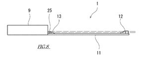
- FIG. 5 is a side view of the front guide 12
- FIG. FIG. 6 is a view taken along arrow VI-VI in FIG. 2.
- a pair of front guides 12 is provided at the tip of the blade 11.
- the front guide 12 is provided so as to protrude from one main surface (upper surface) of the blade 11. Since each front guide 12 has substantially the same structure, only one front guide 12 will be described below, and the other description will be omitted.
- the front guide 12 has a three-step shape in a side view as shown in detail in FIG.
- the front guide 12 has upper and lower two-stage support portions 12c and 12d.
- Each of the upper stage support part 12c and the lower stage support part 12d has an upward surface and can support the substrate 3 placed thereon.
- the front guide 12 has two upper and lower gripping portions 12a and 12b.
- Each of the upper stage gripping part 12 a and the lower stage gripping part 12 b has a surface facing the base end side of the blade 11.
- the upper stage support part 12c and the upper stage holding part 12a form a substantially right angle, and the edge of the substrate 3 placed on the upper stage support part 12c can come into contact with the upper stage holding part 12a.
- the lower support part 12d and the lower support part 12b form a substantially right angle, and the edge of the substrate 3 placed on the lower support part 12d can come into contact with the lower support part 12b.
- the height of the upper support portion 12c from the surface of the blade 11 is different from the height of the lower support portion 12d from the surface of the blade 11, and the upper support portion 12c is higher than the lower support portion 12d.
- the upper stage support part 12c is farther from the surface of the blade 11 than the lower stage support part 12d.
- the upper stage gripping part 12a is located closer to the tip side of the blade 11 than the lower stage gripping part 12b.
- the support parts 12c and 12d and the gripping parts 12a and 12b may be formed on one member, or may be formed on different members.
- a pair of lower rear guides 13 are provided on the base end side of the blade 11 so as to face the pair of front guides 12.
- the lower rear guide 13 has an upward support portion, and this support portion has a portion that matches the height of the lower support portion 12 d of the front guide 12.
- a pair of upper rear guides 130 are provided on the base end side of the blade 11 so as to face the pair of front guides 12.
- the upper rear guide 130 has an upward support portion, and this support portion has a portion that matches the height of the upper support portion 12 c of the front guide 12.
- the upper rear guide 130 is provided to be movable in the front-rear direction along the center line L4 of the blade 11.
- a cylinder 131 is provided as a driving device for the upper rear guide 130.
- a rod 132 extending parallel to the center line L4 is inserted into the cylinder 131 so as to be able to advance and retract.
- a rear guide support member 133 is connected to one end (output end) of the rod 132.
- An upper rear guide 130 is fixed to the rear guide support member 133.
- the upper rear guide 130 is in the casing 9 when it is most retracted, and is in front of the opening 9a of the casing 9 when it is most advanced.
- the opening 11 a is formed in the blade 11.
- the blade 11 is not present in the opening portion 11a, and an object passing through the opening portion 11a can be moved.
- the opening 11a is formed by cutting out the base end of the blade 11.
- the formation method of the opening part 11a is not limited to this.
- the opening 11a is provided over a range of the moving region of the upper rear guide 130 that overlaps the portion in front of the opening 9a of the casing 9 in the blade perpendicular direction. That is, the movement region of the upper rear guide 130 and the blade 11 do not overlap in the blade perpendicular direction.
- the operation of the upper rear guide 130 is controlled by the control device 8. More specifically, as shown in FIG. 4, an air supply device 18 such as a compressor is connected to the cylinder 131. A control valve 134 controlled by the control device 8 is provided between the air supply device 18 and the cylinder 131. The control device 8 switches the air flow rate and direction of the control valve 134 so that the rod 132 extends and the upper rear guide 130 moves forward, or the rod 132 contracts and the upper rear guide 130 moves backward.
- a lower pusher 25 that advances forward from the casing 9 and a cylinder 15 as a drive means for the lower pusher 25.
- a pusher 25 is connected to one end (output end) of the rod 16 of the cylinder 15.
- the lower pusher 25 has a pressing surface facing the tip side of the blade 11, and this pressing surface faces the lower grip portion 12 b of the front guide 12.
- the height of the pressing surface of the pusher 25 from the surface of the blade 11 is set so that the edge of the substrate 3 supported by the lower support portion 12d of the front guide 12 can be pressed. That is, the height of at least a part of the lower pusher 25 is set to coincide with the height of the substrate 3 supported by the lower support portion 12d of the front guide 12.
- the operation of the lower pusher 25 is controlled by the control device 8. More specifically, as shown in FIG. 4, an air supply device 18 such as a compressor is connected to the cylinder 15. A control valve 19 controlled by the control device 8 is provided between the air supply device 18 and the cylinder 15. The control device 8 switches the air flow rate and direction of the control valve 19 so that the rod 16 extends and the lower pusher 25 moves forward, or the rod 16 contracts and the lower pusher 25 moves backward.
- an air supply device 18 such as a compressor is connected to the cylinder 15.
- a control valve 19 controlled by the control device 8 is provided between the air supply device 18 and the cylinder 15. The control device 8 switches the air flow rate and direction of the control valve 19 so that the rod 16 extends and the lower pusher 25 moves forward, or the rod 16 contracts and the lower pusher 25 moves backward.
- the cylinder 15 is provided with a sensor (not shown) for detecting the position of the rod 16.
- the position of the lower pusher 25 can be obtained from the detected position of the rod 16.
- the control device 8 By processing information from this sensor by the control device 8, the presence or absence of the substrate 3 can be determined. That is, when the lower pusher 25 is moved forward from the casing 9 and the lower pusher 25 is held at a position where the predetermined pusher 3 is pressed, the control device 8 has the substrate 3 on the lower support portion 12d. It can be judged. On the other hand, the control device 8 can determine that there is no substrate 3 when the lower pusher 25 has passed the position where the predetermined substrate 3 is pressed.
- an upper pusher 250 that advances forward from the casing 9, and a cylinder 150 as a drive means for the upper pusher 250.
- An upper pusher 250 is connected to one end (output end) of the rod 160 of the cylinder 150.
- the upper pusher 250 has a pressing surface facing the tip side of the blade 11, and this pressing surface faces the upper gripping portion 12 a of the blade 11.
- the height of the pressing surface of the pusher 250 from the surface of the blade 11 is set so that the edge of the substrate 3 supported by the upper support portion 12c of the front guide 12 can be pressed. That is, the height of at least a part of the upper pusher 250 is set to coincide with the height of the substrate 3 supported by the upper support portion 12c.
- the operation of the upper pusher 250 is controlled by the control device 8. More specifically, as shown in FIG. 4, an air supply device 18 such as a compressor is connected to the cylinder 150. A control valve 190 controlled by the control device 8 is provided between the air supply device 18 and the cylinder 150. Then, when the control device 8 switches the flow rate and direction of the air of the control valve 190, the rod 160 extends and the upper pusher 250 moves forward, or the rod 160 contracts and the upper pusher 250 moves backward.
- an air supply device 18 such as a compressor is connected to the cylinder 150.
- a control valve 190 controlled by the control device 8 is provided between the air supply device 18 and the cylinder 150. Then, when the control device 8 switches the flow rate and direction of the air of the control valve 190, the rod 160 extends and the upper pusher 250 moves forward, or the rod 160 contracts and the upper pusher 250 moves backward.
- the cylinder 150 is provided with a sensor (not shown) that detects the position of the rod 160. From the detected position of the rod 160, the position of the upper pusher 250 can be obtained. By processing information from this sensor by the control device 8, the presence or absence of the substrate 3 can be determined. That is, the control device 8 can determine that the substrate 3 is present when the upper pusher 250 is in a position to push the predetermined substrate 3 in a state where the upper pusher 250 has advanced forward from the casing 9. On the other hand, the control device 8 can determine that there is no substrate 3 when the upper pusher 250 has passed the position where the predetermined substrate 3 is pressed.
- FIG. 6 is a view taken along the line VI-VI of the substrate transport hand 1 shown in FIG.
- elements other than the blade 11, the pushers 25 and 250, and the rear guides 13 and 130 are omitted.
- 6 indicates a substrate 3 (hereinafter referred to as “lower substrate 3L” when specifically distinguished) supported by the lower support portion 12d and the lower rear guide 13 of the front guide 12, and the front guide.
- 12 is a substrate 3 supported by an upper support portion 12c and an upper rear guide 130 (hereinafter referred to as “upper substrate 3U” when particularly distinguished).
- the position of the rear guide support member 133 in the blade perpendicular direction and the position of the blade 11 in the blade perpendicular direction partially overlap each other.
- the lowermost surface of the rear guide support member 133 is lower than the uppermost surface of the blade 11.
- the thickness of the rear guide support member 133 can be increased, and the deformation amount of the rear guide support member 133 when the upper rear guide 130 supports the substrate 3 can be reduced.
- the lowermost surface of the upper rear guide 130 is lower than the uppermost surface of the blade 11.
- the lower pusher 25 and the upper pusher 250 are configured differently in the VI-VI arrow view.
- the lower pusher 25 may have a height that does not overlap the upper substrate 3U, and the upper pusher 250 may have a height that does not overlap the lower substrate 3L. By doing so, the lower pusher 25 does not interfere with the upper substrate 3U, and the lower pusher 25 does not interfere with the lower substrate 3L.
- the lower pusher 25 may have a height that overlaps with the upper substrate 3U, and the upper pusher 250 may have a height that overlaps with the lower substrate 3L.
- the stroke of the pushers 25 and 250 means the movement range of the pushers 25 and 250, and is defined by the most backward movement position and the most forward movement position of the pushers 25 and 250.
- the lower support portion 12d of the pair of front guides 12 and the substrate 3 (3L) supported by the lower rear guide 13 are indicated by alternate long and short dash lines.
- This substrate 3 is, for example, a contaminated substrate 3.
- the upper rear guide 130, the lower pusher 25 and the upper pusher 250 are retracted from the substrate 3, and these do not interfere with the substrate 3.
- the lower pusher 25 moves forward from this state, the substrate 3 supported by the lower support portion 12d and the lower rear guide 13 of the front guide 12 is pushed forward by the lower pusher 25.
- the front edge of the substrate 3 comes into contact with the pair of lower gripping portions 12b. In this way, the substrate 3 is gripped by the substrate transport hand 1 by pressing the edge of the substrate 3 from three points of the pair of lower gripping portions 12b and the lower pusher 25 (see FIGS. 7 and 8). .
- the control device 8 monitors a detection signal from a sensor (not shown) for detecting the position of the lower pusher 25 after the lower pusher 25 starts moving forward. 7 and 8, the lower pusher 25 is in a position to push the predetermined substrate 3, so the control device 8 determines that the lower substrate 3 (3 ⁇ / b> L) is on the blade 11.
- the upper support 12c of the pair of front guides 12 and the substrate 3 (3U) supported by the upper rear guide 130 are indicated by alternate long and short dash lines.
- This substrate 3 is, for example, a clean substrate 3.
- the upper rear guide 130 has been advanced to a position where the substrate 3 can be supported.
- the lower pusher 25 and the upper pusher 250 are retracted from the edge of the substrate 3 and do not interfere with the substrate 3.
- the upper pusher 250 moves forward from this state, the substrate 3 supported by the upper support portion 12 c and the upper rear guide 130 of the front guide 12 is pushed forward by the upper pusher 250.
- the front edge of the substrate 3 comes into contact with the pair of upper gripping portions 12a. In this way, the substrate 3 is gripped by the substrate transport hand 1 by pressing the edge of the substrate 3 from three points of the pair of upper gripping portions 12a and the upper pusher 250 (see FIGS. 11 and 12). .
- the control device 8 monitors a detection signal from a sensor (not shown) for detecting the position of the upper pusher 250 after the upper pusher 250 starts moving forward. In the state shown in FIGS. 11 and 12, the upper pusher 250 is in a position to press the predetermined substrate 3, and therefore the control device 8 determines that the upper substrate 3 (3 U) is on the blade 11.
- the contaminated substrate 3 is supported by the lower support portion 12d and the lower rear guide 13 of the pair of front guides 12, and is gripped by the lower grip portion 12b and the lower pusher 25 of the pair of front guides 12.
- the clean substrate 3 is supported by the upper support portion 12 c and the upper rear guide 130 of the pair of front guides 12 and is gripped by the upper grip portion 12 a and the upper pusher 250 of the pair of front guides 12.
- the substrate transfer hand 1 is contaminated by the contaminated substrate 3 by properly using the support portion and the gripping portion for the contaminated substrate and the clean substrate, and the clean substrate held by the substrate transfer hand 1 is used. 3 can be prevented from being contaminated.
- the clean substrate and the contaminated substrate are held at different heights on the substrate transport hand 1, it is desirable to hold the clean substrate at a high position. This is because the pollutant falls from the top to the bottom due to an air flow called downflow for maintaining a clean environment.
- FIG. 13 is a diagram illustrating the stroke of the lower pusher 25 and the stroke of the upper pusher 250.
- the stroke of the lower pusher 25 depends on the advance / retreat distance of the rod 16 of the cylinder 15, the relationship between the position of the substrate 3 held by the substrate transport hand 1 and the mounting position of the cylinder 15, and the lower pusher 25 provided as necessary. It is adjusted depending on the attachment position of a stopper (not shown) for adjusting the stroke, the attachment position of the lower pusher 25 with respect to the rod 16, and the like.
- the stroke of the upper pusher 250 is determined by the advance / retreat distance of the rod 160 of the cylinder 150, the relationship between the position of the substrate 3 held by the substrate transport hand 1 and the mounting position of the cylinder 150, and the upper pusher provided as necessary. It is adjusted depending on the mounting position of a stopper (not shown) for adjusting the stroke of 250, the mounting position of the upper pusher 250 with respect to the rod 160, and the like.
- a position 25a is a state where the lower pusher 25 is most retracted
- a position 25b is a state where the lower substrate 3L is on the blade 11, and the lower pusher 25 is pushing the lower substrate 3L
- a position 25c is The position of 25 points in each state in which the lower substrate 3L is not on the blade 11 and the pusher 25 is most advanced is shown.
- a position 250a is a state in which the upper pusher 250 is most retracted
- a position 250b is a state in which the upper substrate 3U is on the blade 11, and the upper pusher 250 is pressing the upper substrate 3U
- 250c shows the position of 250 points in each state where the upper substrate 3U is not on the blade 11 and the upper pusher 250 is most advanced.
- the stroke of the lower pusher 25 is set so that the lower pusher 25 is located behind the upper substrate 3U in a state where 25point is at the position 25c.
- the stroke of the lower pusher 25 is in front of the two substrates 3 that are held by the substrate transfer hand 1 while being shifted from each other in the front-rear direction (and the up-down direction) with the lower-stage pusher 25 moving forward most.
- the substrate 3 and the lower pusher 25 are set so as not to interfere with each other. In this way, regardless of the position of the lower pusher 25, it is possible to avoid the interference between the lower pusher 25 and the substrate 3 that is shifted forward among the two substrates 3 that are held shifted in the front-rear direction. .
- the stroke of the upper pusher 250 is set so that the upper pusher 250 is located behind the lower substrate 3L when 250 points are at the position 250a.
- the stroke of the upper pusher 250 is behind the two substrates 3 that are held by the substrate transfer hand 1 while being shifted from each other in the front-rear direction (and the vertical direction) with the upper-stage pusher 250 retracted most.
- the substrate 3 and the upper pusher 250 are set so as not to interfere with each other. In this way, if the upper pusher 250 is moved most backward, interference between the rear substrate 3 and the upper pusher 250 out of the two substrates 3 that are held while being shifted in the front-rear direction can be avoided. .
- the substrate transport hand 1 includes the casing 9, the thin blade 11 having the base end coupled to the casing 9, and the tip of the blade 11. 11, a front guide 12 having a lower support portion (first support portion) 12 d and an upper support portion (second support portion) 12 c having different heights from the substrate 11, and a base end portion of the blade 11.
- a lower rear guide (first rear guide) 13 having a portion where the lower support portion 12d of the guide 12 and the height from the blade 11 coincide with each other, and an upper support portion 12c of the front guide 12 provided on the base end side of the blade 11.
- an upper rear guide (second rear guide) 130 having a portion whose height from the blade 11 coincides with each other, and is provided in the casing 9 and supported by the blade 11.
- An output terminal for forward and backward movement relative to the plate, and a cylinder (driving device) 131 which moves in a region which does not overlap the upper rear guide 130 coupled with the output end to the blade 11 and the blade perpendicular direction.
- the transfer robot 2 includes an arm 40 and a substrate transfer hand 1 attached to the tip of the arm 40.
- the upper rear guide 130 provided on the base end side of the substrate transport hand 1 moves forward and backward with respect to the substrate 3 supported by the blade 11.
- a certain cylinder 131 is accommodated in the casing 9. That is, the upper rear guide 130 and its driving device are arranged together at the base end of the substrate transport hand 1. Since the upper rear guide 130 moves in a region that does not overlap the blade 11 and the vertical direction of the blade, the upper rear guide 130 and its driving device can be provided avoiding the blade 11. Therefore, a reduction in the strength of the blade 11 due to the provision of the upper rear guide 130 and the cylinder 131 which is a driving device thereof is avoided. That is, the blade 11 has an appropriate strength, and the stability of the operation of the substrate transport hand 1 is not impaired.
- the height of the lower support portion (first support portion) 12d from the blade 11 is lower than the height of the upper support portion (second support portion) 12c from the blade 11. .
- the lower support portion 12d being lower than the upper support portion 12c means that the lower rear guide 13 is lower than the upper rear guide 130.
- the upper rear guide 130 can be retracted from the substrate 3 when the substrate 3 is supported by the cooperation of the lower rear guide 13 and the lower support portion 12d. That is, the upper rear guide 130 can be kept away from the contamination source. Since the pollutant falls from the top to the bottom, if the rear guide (upper rear guide 130) that can be moved away from the pollution source is placed on the top and the other on the bottom, the rear guide (upper rear guide 130) placed on the top Cleanliness can be further improved.
- the contaminated substrate 3 is supported by the combination of the lower rear guide 13 and the lower support portion 12d, and the clean substrate 3 is combined by the combination of the upper rear guide 130 and the upper support portion 12c. It is good to support.
- FIGS. 14 is an enlarged plan view of the substrate transfer hand 1A according to the first modification
- FIG. 15 is a view taken along the arrow XV-XV in FIG. 14,
- FIG. 16 shows a state in which the substrate transfer hand 1A in FIG.
- FIG. 17 is a plan view showing a state in which the substrate transport hand 1A of FIG. 14 grips the upper substrate 3U.
- the same or similar members as those in the above-described embodiment may be denoted by the same reference numerals in the drawings, and description thereof may be omitted.
- the substrate transport hand 1A according to Modification 1 is different from the substrate transport hand 1 according to the above embodiment in the configuration of the lower pusher 25 and the upper pusher 250, and the other configurations are substantially the same. Therefore, in the following, the configurations of the lower pusher 25A and the upper pusher 250A of the substrate transport hand 1A according to Modification 1 will be described in detail, and the description of the remaining configuration will be omitted.
- a pair of lower pushers 25 ⁇ / b> A is provided on the base end side of the blade 11.
- the pair of lower pushers 25 ⁇ / b> A are arranged symmetrically via the center line L ⁇ b> 4 of the blade 11.
- the pair of lower pushers 25 ⁇ / b> A are attached to both ends of a pusher support member 111 extending in an arc shape in a direction orthogonal to the center line L ⁇ b> 4 of the blade 11.
- the central portion of the pusher support member 111 is connected to the tip portion of the rod 16.
- a pair of upper pushers 250A are provided on the base end side of the blade 11.
- the pair of upper pushers 250 ⁇ / b> A are arranged symmetrically via the center line L ⁇ b> 4 of the blade 11.
- the pair of upper pushers 250A are attached to both ends of the pusher support member 110 extending in an arc shape in a direction orthogonal to the center line L4 of the blade 11.
- the central portion of the pusher support member 110 is connected to the tip portion of the rod 160.
- the distance from the upper pusher 250A to the center line L4 of the blade 11 is smaller than the distance from the lower pusher 25A to the center line L4 of the blade 11. That is, the pair of upper pushers 250A is arranged inside the pair of lower pushers 25A when the center line L4 is the center. Further, the distance from these pushers 25A, 250A to the center line L4 of the blade 11 is larger than the distance from the rear guides 13, 130 to the center line L4 of the blade 11. In other words, the pushers 25A and 250A are disposed outside the rear guides 13 and 130 when the center line L4 is the center.
- the pusher support member 111 and the pusher support member 110 are disposed higher than the lower rear guide 13 and the upper rear guide 130 from the surface of the blade 11.
- the pair of lower pushers 25 ⁇ / b> A is attached to the pusher support member 111 so as to hang down from the pusher support member 111.
- the pair of lower pushers 25 ⁇ / b> A has a pressing surface facing the tip side of the blade 11, and the pressing surfaces are at the same level as and opposed to the lower holding portion 12 b of the front guide 12.
- the pair of upper pushers 250 ⁇ / b> A is attached to the pusher support member 110 so as to hang down from the pusher support member 110.
- the pair of upper pushers 250 ⁇ / b> A has a pressing surface facing the tip side of the blade 11, and the pressing surfaces are at the same level as the upper gripping portion 12 a of the blade 11 and face each other. Note that these pushers 25 ⁇ / b> A and 250 ⁇ / b> A are arranged at a position higher than the bottom surface of the blade 11. In this way, when another substrate transfer hand 1 (not shown) is provided under the substrate transfer hand 1A to form a so-called double-handed transfer robot 2, the two substrate transfer hands 1 Interference can be prevented.
- the substrate 3 can be pressed more stably by pressing the edge of the substrate 3 in two places by the pusher 25A or 250A. Further, since the pusher support members 111 and 110 are elongated members, when the substrate 3 is pushed by the pushers 25A and 250A, the pusher support members 111 and 110 are elastically deformed so that the substrate 3 can be gripped more flexibly. .
- FIGS. 18 is an enlarged plan view of the substrate transport hand 1B according to the second modification
- FIG. 19 is a view taken along the arrow XIX-XIX in FIG. 18,
- FIG. 20 shows a state in which the substrate transport hand 1B in FIG. FIG.
- the same or similar members as those in the above-described embodiment may be denoted by the same reference numerals in the drawings, and description thereof may be omitted.
- the substrate transport hand 1B according to Modification 2 is different from the substrate transport hand 1 according to the above embodiment in the arrangement and configuration of the upper rear guide 130 and the rear guide support member 133, and the remaining configuration is substantially the same. Are the same. Therefore, hereinafter, the configurations of the upper rear guide 130B and the rear guide support member 133B of the substrate transport hand 1B according to Modification 2 will be described in detail, and the description of the remaining configurations will be omitted.
- the pair of upper rear guides 130 is disposed inside the pair of lower rear guides 13 when the center line L4 of the blade 11 is set at the center.
- the pair of upper rear guides 130B is disposed outside the pair of lower rear guides 13 when the center line L4 of the blade 11 is the center.
- the pair of upper rear guides 130 ⁇ / b> B are disposed outside the blade 11.
- a rear guide support member 133B is provided between the rod 132 of the cylinder 131 and the upper rear guide 130.
- the rear guide support member 133B is a member for taking out the upper rear guide 130 to a region (here, both sides of the blade 11) that does not overlap the blade 11 and the vertical direction of the blade.
- the rear guide support member 133B includes a first member 200 extending in a direction orthogonal to the center line L4 of the hand body, and a second member 201 coupled to both ends of the first member 200.
- the first member 200 extends to the outside of the blade 11 on both sides across the center line L4 of the hand body. Further, the first member 200 is connected to the rod 132 so as to be higher than the lower pusher 25, the upper pusher 250, and the lower rear guide 13.
- the second member 201 is formed in an L shape by a vertical portion joined to the first member 200 and a horizontal portion to which the upper rear guide 130B is attached.
- the upper rear guide 130B attached to the second member 201 has an upward support portion, and this support portion has a portion that coincides with the height of the upper support portion 12c of the front guide 12.
- the position in the blade normal direction of at least a portion of the second member 201 of the upper rear guide 130B or the rear guide support member 133B and the position in the blade normal direction of the blade 11 may overlap. That is, at least a part of the second member 201 of the upper rear guide 130B or the rear guide support member 133B and the blade 11 may be at the same level. In this way, the thickness of the substrate transport hand 1 including the rear guide support member 133B can be suppressed, and is particularly useful when the substrate transport hand 1 includes a plurality of hands.
- the upper rear guide 130B having the above configuration moves forward and backward along the center line L4 of the blade 11.
- the upper rear guide 130B and the rear guide support member 133B move within a range that does not overlap the blade 11 and the blade perpendicular direction.
- the operation of the upper rear guide 130B is realized by the action of the cylinder 131 controlled by the control device 8 as in the above-described embodiment.
- the blade 11 has a Y-shape as viewed from the direction of the blade normal, but the blade 11 does not have to be divided into two forks.
- the blade 11 may be composed of a plurality of members.
- the upper rear guide 130 and the rear guide support member 133 are separate members.
- the upper rear guide 130 and the rear guide support member 133 may be integrally formed.
- another element may be interposed between the upper rear guide 130 and the rear guide support member 133.
- the upper rear guide 130 may be provided directly on the rod 132 of the cylinder 131. In short, it is sufficient that the movement of the rod 132 of the air cylinder 131 is transmitted to the upper rear guide 130 and the rear guide 130 is disposed at an appropriate position.
- the pushers 25A and 250A and the pusher support members 111 and 110 are separate members. However, the pushers 25A and 250A and the pusher support members 111 and 110 may be integrally configured. Further, other elements may be interposed between the pushers 25A and 250A and the pusher support members 111 and 110. In short, the movement of the rods 16 and 160 of the air cylinders 15 and 150 may be transmitted to the pushers 25A and 250A, and the pushers 25A and 250A may be arranged at appropriate positions.
- the pushers 25 and 250 and the rear guide 130 may be moved by a moving means other than the cylinder and the rod.
- the moving direction of the output end of the moving means for moving the pushers 25, 250 and the rear guide 130 is not limited to the front-rear direction of the blade 11, and any direction can be used as long as it can move forward and backward with respect to the substrate 3 supported by the blade 11. Such a direction may be used.
- the movement path of the output end of the moving means for moving the pushers 25 and 250 and the rear guide 130 is not limited to a straight line, and may be a circle, a curve, or a combination thereof.
- Substrate transport hand 2 Transport robot 3, 3L, 3U: Substrate 8: Control device 9: Casing 11: Blade 11a: Opening portion 12: Front guide 12a: Upper gripping portion 12b: Lower gripping portion 12c: Upper support 12d: Lower support 13: Lower rear guide 15: Cylinder 16: Rod 18: Air supply device 19: Control valve 25, 25A: Lower pusher 110: Pusher support member 111: Pusher support member 130: Upper rear guide 131 : Cylinder (drive device) 132: Rod 133, 133B: Rear guide support member 150: Cylinder 160: Rod 250, 250A: Upper pusher
Abstract
基板搬送ハンドは、ケーシングと、ケーシングにその基端部が結合された薄板状のブレードと、ブレードの先端部に設けられ、ブレードからの高さが互いに異なる基板の第1支持部及び第2支持部を有するフロントガイドと、ブレードの基端部に設けられ、フロントガイドの第1支持部とブレードからの高さが一致する部分を有する第1リアガイドと、ブレードの基端側に設けられ、フロントガイドの第2支持部とブレードからの高さが一致する部分を有する第2リアガイドと、ケーシング内に設けられ、ブレードに支持される基板に対して進退移動する出力端を有し、当該出力端と結合された第2リアガイドをブレードと当該ブレードの垂線方向に重ならない領域で移動させる駆動装置と、を備える。
Description
本発明は、半導体ウエハやガラス基板等の基板を保持して搬送するための基板搬送ハンド、及びそれを備えるロボットに関する。
半導体ウエハやガラス基板等の基板を搬送する搬送ロボットは、その先端部にエンドエフェクタ、例えばハンドを有しており、このハンドにより基板を保持して搬送するように構成されている。基板を保持するハンドとしては、例えば、基板を把持する、エッジグリップハンドと呼ばれるものがある。ところで、半導体プロセスには、基板の洗浄プロセスのように、洗浄前の汚染された基板と、洗浄後の清浄な基盤が、同じプロセス中に混在する場合がある。このような場合に、搬送ロボットの1つのハンドで基板搬送を行うと、汚染された基板によってハンドが汚染され、その汚染されたハンドで保持された清浄な基板が汚染されてしまう。このような基板の汚染を防ぐためのハンドとして、例えば特許文献1に記載のハンドがある。
特許文献1には、基板を保持する複数の爪を二組有するハンドが記載されている(図10等参照)。特許文献1に記載のハンドでは、一方の組の爪を汚染された基板用とし、他方の組の爪を清浄な基板用とすることで、上記のような基板の汚染を防いでいる。
特許文献1に記載のハンドにおいて、二組の複数の爪は、一方の組の爪に保持される基板が、他方の組の爪に保持される基板に比べてわずかに高くなるように構成されている。このようにハンドを構成することにより、薄くて、コンパクトな枚葉式ワーク把持装置を提供することが、特許文献1の目的である。
特許文献1に記載のハンドでは、ブレードの先端部に設けられた爪をスライドさせるための動力伝達部材として、ブレード基端側からブレード先端側に至る金属ベルトが使用されている。ところが、このような金属ベルトを通すための中空部がブレードに設けられると、この中空部によってブレードの強度が下がる。ブレードは薄板状の部材であり、強度低下により撓みが生じ易くなると、ハンドの動作の安定性が損なわれるおそれがある。
そこで本発明は、1枚のブレードに複数組の基板支持部を備えた基板搬送ハンドであって、安定した動作を実現するもの、及び、この基板搬送ハンドを備えるロボットを提供することを目的としている。
本発明の一態様に係る基板搬送ハンドは、
ケーシングと、
前記ケーシングにその基端部が結合された薄板状のブレードと、
前記ブレードの先端部に設けられ、前記ブレードからの高さが互いに異なる基板の第1支持部及び第2支持部を有するフロントガイドと、
前記ブレードの基端部に設けられ、前記フロントガイドの前記第1支持部と前記ブレードからの高さが一致する部分を有する第1リアガイドと、
前記ブレードの基端側に設けられ、前記フロントガイドの前記第2支持部と前記ブレードからの高さが一致する部分を有する第2リアガイドと、
前記ケーシング内に設けられ、前記ブレードに支持される基板に対して進退移動する出力端を有し、当該出力端と結合された前記第2リアガイドを前記ブレードと当該ブレードの垂線方向に重ならない領域で移動させる駆動装置と、を備えることを特徴としている。ここで、「ブレードの垂線方向」とは、ブレードの主面を垂直に貫く方向及びそれと平行な方向をいう。
また、本発明の一態様に係るロボットは、アームと、前記アームの先端部に装着された上記基板搬送ハンドを備えることを特徴としている。
上記基板搬送ハンド及びそれを備えるロボットでは、ブレードの基端側に設けられた第2リアガイドがブレードに支持された基板に対して進退移動し、その駆動装置はケーシングに収容されている。つまり、第2リアガイド及びその駆動装置は、ハンドの基端部に集約して配置されている。そして、第2リアガイドは、ブレードと当該ブレードの垂線方向に重複しない領域で移動することから、ブレードを避けて第2リアガイド及びその駆動装置を設けることができる。よって、第2リアガイド及びその駆動装置を設けることに起因するブレードの強度低下が回避され、ハンドの動作の安定性が維持される。
本発明によれば、1枚のブレードに複数組の基板支持部を備えた基板搬送ハンドであって、安定した動作を実現するもの、及び、この基板搬送ハンドを備えるロボットを提供することができる。
以下、図面を参照して本発明の実施の形態を説明する。
[搬送ロボット2の構成]
まず、本発明の一実施形態に係る基板搬送ハンド1を備える搬送ロボット2の基本構成について、図1及び図2を参照しつつ説明する。図1は本発明の一実施形態に係る基板搬送ハンド1を備える搬送ロボット2を示す斜視図であり、図2は基板搬送ハンド1の拡大平面図である。以下において、ブレード11を水平にしたときに、基板3が載置される側を「上」とし、その反対側を「下」とする。また、基板搬送ハンド1から見たときに、基板搬送ハンド1の先端側を「前」とし、その反対側を「後」とする。
まず、本発明の一実施形態に係る基板搬送ハンド1を備える搬送ロボット2の基本構成について、図1及び図2を参照しつつ説明する。図1は本発明の一実施形態に係る基板搬送ハンド1を備える搬送ロボット2を示す斜視図であり、図2は基板搬送ハンド1の拡大平面図である。以下において、ブレード11を水平にしたときに、基板3が載置される側を「上」とし、その反対側を「下」とする。また、基板搬送ハンド1から見たときに、基板搬送ハンド1の先端側を「前」とし、その反対側を「後」とする。
搬送ロボット2は、基板3を搬送するロボットであり、例えば、半導体処理設備に備わっている。基板3は、半導体プロセス等において用いられる薄い板である。基板には、例えば、半導体ウエハ、ガラスウエハ、サファイヤ(単結晶アルミナ)ウエハ等が含まれる。半導体ウエハには、例えば、シリコンウエハ、シリコン以外の半導体単体のウエハ、化合物半導体のウエハ等が含まれる。ガラスウエハには、例えば、FPD(Flat Panel Display)用ガラス基板、MEMS(Micro Electro Mechanical Systems)用ガラス基板等が含まれる。以下、基板の一種である半導体プロセス用ウエハを搬送する搬送ロボット2を例にとって説明する。
半導体処理設備には、熱処理、不純物導入処理、薄膜形成処理、リソグラフィー処理、洗浄処理及び平坦化処理等のプロセス処理を施すための半導体処理装置(図示せず)が備わっている。搬送ロボット2は、図示しないフープに収容される半導体プロセス用ウエハ(基板3)を持って各半導体処理装置内の予め定められた収容位置に搬送するように構成されている。また、搬送ロボット2は、各半導体処理装置内に予め定められた収容位置に置かれた基板3を持って、他の半導体処理装置内に搬送するように構成されている。
搬送ロボット2は、いわゆる水平多関節型の3軸ロボットである。搬送ロボット2は、半導体処理設備のケーシングに固定される基台4と、基台4に支持されたアーム40と、アーム40の先端部に装着された基板搬送ハンド1とを備える。
基台4には、上下方向(図1の矢符B)に昇降する昇降軸5が設けられている。昇降軸5は、図示しない電動モータ等で昇降できるように構成されている。このように昇降可能な昇降軸5の上端部には、第1リンク6が取り付けられている。第1リンク6は、水平方向に延びる長尺の部材であり、その長手方向の一端部が昇降軸5に鉛直な軸線L1回りに回動可能に取り付けられている。第1リンク6は、図示しない電気モータにより回動駆動できるように構成されている。また、第1リンク6の長手方向他端部には、第2リンク7が取り付けられている。第2リンク7もまた、水平方向に延びる長尺状の部材であり、その長手方向一端部が第1リンク6に鉛直な軸線L2回りに回動可能に取り付けられている。第2リンク7は、図示しない電動モータにより回動駆動できるように構成されている。上記の昇降軸5、第1リンク6、及び第2リンク7などにより、アーム40が構成されている。
第2リンク7の長手方向他端部には、基板搬送ハンド1の基端部が鉛直な軸線L3回りに回動可能に取り付けられている。基板搬送ハンド1は、図示しない電動モータにより回動駆動できるように構成されている。これら昇降軸5の昇降、並びに第1リンク6、第2リンク7及び基板搬送ハンド1の回動は、後述する制御装置8により制御されている。
[基板搬送ハンド1の概略構成]
基板搬送ハンド1は、基板3を把持して保持できるように構成されている。基板搬送ハンド1は、その基端部にケーシング9を有する。ケーシング9は、矩形状の中空の箱体である。ケーシング9の下面は、第2リンク7に取り付けられている。また、ケーシング9は、基板搬送ハンド1の先端側を向いた側面に開口部9aを有している。
基板搬送ハンド1は、基板3を把持して保持できるように構成されている。基板搬送ハンド1は、その基端部にケーシング9を有する。ケーシング9は、矩形状の中空の箱体である。ケーシング9の下面は、第2リンク7に取り付けられている。また、ケーシング9は、基板搬送ハンド1の先端側を向いた側面に開口部9aを有している。
ケーシング9の開口部9aには、ブレード11の基端部が固定されている。ブレード11は、先端側が二股に分かれており、ブレード11の垂線方向(以下、「ブレード垂線方向」と表す)から視てY字状に形成された薄板状部材である。なお、ブレード垂線方向とは、ブレード11の主面を垂直に貫く方向と、これに平行な方向とをいう。ブレード11が水平のときは、ブレード垂線方向は垂直方向と一致する。
ブレード11の二股に分かれた各々の先端部分には、フロントガイド12が設けられている。また、ブレード11の基端側には、一対のフロントガイド12に対向するように二対のリアガイド13,130が設けられている。一対のフロントガイド12,12と各対のリアガイド13,130とは、基板3を支持する機能を有する。それ故、これらは、基板3の形状に応じて、当該基板3を適切に支持できるような位置及び形状に形成されている。基板3の形状は任意であるが、以下では、基板3の形状が円形として説明する。
更に、基板搬送ハンド1には、ブレード11の基端側に、ブレード11の中心線L4と平行に進退移動可能なプッシャー25,250が設けられている。プッシャー25,250の駆動機構(シリンダ15,150(図3、参照))はケーシング9に内装されている。プッシャー25,250は、リアガイド13,130及びフロントガイド12によってブレード11の上面に支持された基板3を、一対のフロントガイド12に押し付ける。これにより、プッシャー25,250と一対のフロントガイド12によって基板3が把持される。
搬送ロボット2は、制御装置8を備えている。制御装置8は、昇降軸5を昇降させる図示しない電動モータ、第1リンク6、第2リンク7及び基板搬送ハンド1を夫々回動させる図示しない電動モータに接続されている。制御装置8は、予め定められたプログラムに基づいて各電動モータを制御するように構成されている。また、制御装置8は、後述するように、上段リアガイド130、下段プッシャー25、及びプッシャー250の駆動機構と接続されており、これらの動作を制御する。
このような制御装置8に制御される搬送ロボット2は、昇降軸5の昇降、第1リンク6、第2リンク7及び基板搬送ハンド1の回動によって基板搬送ハンド1を所望の位置へと動かし、基板搬送ハンド1により基板3を把持し、また把持した基板3を放す動作を行う。
[基板搬送ハンド1の構成]
以下では、本発明に係るハンドの一実施形態である基板搬送ハンド1について更に詳細に説明する。図3は図2に示す基板搬送ハンド1の概略側面図、図4は図2に示す基板搬送ハンド1の駆動系統の構成を示すブロック図、図5はフロントガイド12の側面図、図6は図2のVI-VI矢視図である。
以下では、本発明に係るハンドの一実施形態である基板搬送ハンド1について更に詳細に説明する。図3は図2に示す基板搬送ハンド1の概略側面図、図4は図2に示す基板搬送ハンド1の駆動系統の構成を示すブロック図、図5はフロントガイド12の側面図、図6は図2のVI-VI矢視図である。
図2及び図3に示すように、ブレード11の先端部には、一対のフロントガイド12が設けられている。フロントガイド12は、ブレード11の一方の主面(上面)から突出するように設けられている。なお、各フロントガイド12は、実質的に同一の構造を有するので、以下では一方のフロントガイド12について説明し、他方の説明を省略する。
フロントガイド12は、特に図5に詳細に示されるように、側面視で3段の階段状を呈している。フロントガイド12は、上下二段の支持部12c,12dを有している。上段支持部12c及び下段支持部12dはいずれも上向きの面を有し、載置された基板3を支持することができる。また、フロントガイド12は、上下二段の把持部12a,12bを有している。上段把持部12a及び下段把持部12bはいずれもブレード11の基端側を向いた面を有している。上段支持部12cと上段把持部12aは略直角を成し、上段支持部12cに載置された基板3のエッジが、上段把持部12aに当接することができる。また、下段支持部12dと下段把持部12bは略直角を成し、下段支持部12dに載置された基板3のエッジが下段把持部12bに当接することができる。
上段支持部12cのブレード11の表面からの高さと下段支持部12dのブレード11の表面からの高さは異なり、上段支持部12cは下段支持部12dより高い。換言すれば、上段支持部12cは、下段支持部12dよりもブレード11の表面から離れている。また、上段把持部12aは、下段把持部12bより、ブレード11の先端側に位置している。なお、支持部12c、12d及び把持部12a,12bは、1つの部材に形成されていてもよく、それぞれ別の部材に形成されていてもよい。
ブレード11の基端側には、一対のフロントガイド12に対向するように、一対の下段リアガイド13が設けられている。下段リアガイド13は上向きの支持部を有し、この支持部は、フロントガイド12の下段支持部12dの高さと一致する部分を有する。
また、ブレード11の基端側には、一対のフロントガイド12に対向するように一対の上段リアガイド130が設けられている。上段リアガイド130は上向きの支持部を有し、この支持部はフロントガイド12の上段支持部12cの高さと一致する部分を有する。
上段リアガイド130は、ブレード11の中心線L4に沿って前後方向に移動可能に設けられている。ケーシング9内には、上段リアガイド130の駆動装置としてのシリンダ131が設けられている。シリンダ131には、中心線L4と平行に延びるロッド132が進退可能に挿入されている。ロッド132の一端部(出力端)には、リアガイド支持部材133が接続されている。リアガイド支持部材133には上段リアガイド130が固定されている。
上段リアガイド130は、最も後退しているときはケーシング9内にあり、最も前進しているときはケーシング9の開口部9aよりも前方にある。そこで、ケーシング9の開口部9aから前方へ進出した上段リアガイド130及びリアガイド支持部材133とブレード11との干渉を避けるために、ブレード11に開口部11aが形成されている。この開口部11aには、ブレード11が存在せず、この開口部11aを貫いた物体の移動が可能である。本実施形態においては、ブレード11の基端部が切り欠かれることによって、開口部11aが形作られている。但し、開口部11aの形成方法はこれに限定されない。
上記の開口部11aは、上段リアガイド130の移動領域のうちケーシング9の開口部9aよりも前方の部分と、ブレード垂線方向に重なる範囲に亘って設けられている。つまり、上段リアガイド130の移動領域と、ブレード11とは、ブレード垂線方向に重複しない。
上段リアガイド130の動作は制御装置8により制御される。より詳細には、図4に示すように、シリンダ131には、コンプレッサ等のエア供給装置18が接続されている。エア供給装置18とシリンダ131との間には、制御装置8によって制御される制御弁134が設けられている。そして、制御装置8が、制御弁134のエアの流量及び方向を切り替えることにより、ロッド132が伸びて上段リアガイド130が前進し、又は、ロッド132が縮んで上段リアガイド130が後退する。
ケーシング9内には、ケーシング9から前方へ進出する下段プッシャー25と、この下段プッシャー25の駆動手段としてのシリンダ15が設けられている。シリンダ15のロッド16の一端部(出力端)には、プッシャー25が接続されている。下段プッシャー25は、ブレード11の先端側を向いた押圧面を有し、この押圧面はフロントガイド12の下段把持部12bと対向している。プッシャー25の押圧面のブレード11の表面からの高さは、フロントガイド12の下段支持部12dに支持された基板3のエッジを押すことができるように設定されている。すなわち、下段プッシャー25の、少なくとも一部の高さは、フロントガイド12の下段支持部12dに支持された基板3の高さと一致するように設定されている。
下段プッシャー25の動作は制御装置8により制御される。より詳細には、図4に示すように、シリンダ15には、コンプレッサ等のエア供給装置18が接続されている。エア供給装置18とシリンダ15との間には、制御装置8によって制御される制御弁19が設けられている。そして、制御装置8が、制御弁19のエアの流量及び方向を切り替えることにより、ロッド16が伸びて下段プッシャー25が前進し、又は、ロッド16が縮んで下段プッシャー25が後退する。
シリンダ15には、ロッド16の位置を検出するセンサ(図示せず)が設けられている。検出されたロッド16の位置から、下段プッシャー25の位置を求めることができる。このセンサからの情報を制御装置8で処理することにより、基板3の有無を判断できる。すなわち、制御装置8は、下段プッシャー25がケーシング9から前方へ進出した状態で、下段プッシャー25が所定の基板3を押す位置に保持されている場合は、基板3が下段支持部12d上に有ると判断できる。一方、制御装置8は、下段プッシャー25が、所定の基板3を押す位置を行き過ぎている場合は、基板3が無いと判断できる。
ケーシング9内には、ケーシング9から前方へ進出する上段プッシャー250と、この上段プッシャー250の駆動手段としてのシリンダ150が設けられている。シリンダ150のロッド160の一端部(出力端)には、上段プッシャー250が接続されている。上段プッシャー250は、ブレード11の先端側を向いた押圧面を有し、この押圧面はブレード11の上段把持部12aと対向している。プッシャー250の押圧面のブレード11の表面からの高さは、フロントガイド12の上段支持部12cに支持された基板3のエッジを押すことができるように設定されている。すなわち、上段プッシャー250の、少なくとも一部の高さは、上段支持部12cに支持された基板3の高さと一致するように設定されている。
上段プッシャー250の動作は制御装置8により制御される。より詳細には、図4に示すように、シリンダ150には、コンプレッサ等のエア供給装置18が接続されている。エア供給装置18とシリンダ150との間には、制御装置8によって制御される制御弁190が設けられている。そして、制御装置8が、制御弁190のエアの流量及び方向を切り替えることにより、ロッド160が伸びて上段プッシャー250が前進し、又は、ロッド160が縮んで上段プッシャー250が後退する。
シリンダ150には、ロッド160の位置を検出するセンサ(図示せず)が設けられている。検出されたロッド160の位置から、上段プッシャー250の位置を求めることができる。このセンサからの情報を制御装置8で処理することにより、基板3の有無を判断できる。すなわち、制御装置8は、上段プッシャー250がケーシング9から前方へ進出した状態で、所定の基板3を押す位置にある場合は、基板3が有ると判断できる。一方、制御装置8は、上段プッシャー250が、所定の基板3を押す位置を行き過ぎている場合は、基板3が無いと判断できる。
図6は、図2に示される基板搬送ハンド1のVI-VI矢視図である。図6では、ブレード11、プッシャー25,250及びリアガイド13,130以外の要素は省略されている。図6に示されている一点鎖線は、フロントガイド12の下段支持部12dと下段リアガイド13によって支持される基板3(以下、特に区別するときには「下の基板3L」という。)と、フロントガイド12の上段支持部12cと上段リアガイド130によって支持される基板3(以下、特に区別するときには「上の基板3U」という。)である。
図6に示されているように、リアガイド支持部材133のブレード垂線方向の位置と、ブレード11のブレード垂線方向の位置とは、一部で重なっている。言い換えると、リアガイド支持部材133の最下面は、ブレード11の最上面より低い。このような構成でも、前記のように、リアガイド130とリアガイド支持部材133が前方へ移動する場合には、リアガイド130とリアガイド支持部材133は、開口部11aの範囲内、すなわち、ブレード11と重ならない範囲内で移動する。よって、リアガイド支持部材133がブレード11に干渉しない。このようにすることで、リアガイド支持部材133の厚みを大きくでき、上段リアガイド130が基板3を支持する場合のリアガイド支持部材133の変形量を小さくすることができる。なお、リアガイド支持部材133とリアガイド130が一体的に構成されている場合は、上段リアガイド130の最下面が、ブレード11の最上面より低いことになる。
図6に示されているように、下段プッシャー25と上段プッシャー250は、VI-VI矢視図において、段違いに構成されている。下段プッシャー25は、上の基板3Uと重ならない高さとされていてもよく、上段プッシャー250は、下の基板3Lと重ならない高さとされていてもよい。このようにすることで、下段プッシャー25が上の基板3Uと干渉せず、下段プッシャー25が下の基板3Lと干渉しない。下段プッシャー25は、上の基板3Uとも重なる高さとされていてもよく、上段プッシャー250は、下の基板3Lと重なる高さとされていてもよい。このようにした場合でも、後で説明するように、下段プッシャー25と上段プッシャー250のストロークを調整することで、下段プッシャー25が上の基板3Uと干渉せず、上段プッシャー250が下の基板3Lと干渉しないようにすることができる。ここで、プッシャー25,250のストロークとは、プッシャー25,250の移動範囲を意味し、プッシャー25,250の、最も後方への移動位置と、最も前方への移動位置とによって規定される。
[基板搬送ハンド1の動作]
ここで、上記構成の基板搬送ハンド1の動作について説明する。なお、以下に説明する上段リアガイド130、下段プッシャー25、及び上段プッシャー250の動作は、特に説明しないが制御装置8の制御を受けた対応するシリンダ131,15,150の働きによって実現される。
ここで、上記構成の基板搬送ハンド1の動作について説明する。なお、以下に説明する上段リアガイド130、下段プッシャー25、及び上段プッシャー250の動作は、特に説明しないが制御装置8の制御を受けた対応するシリンダ131,15,150の働きによって実現される。
図2及び図3には、一対のフロントガイド12の下段支持部12dと、下段リアガイド13に支持された基板3(3L)が、一点鎖線で示されている。この基板3は、例えば、汚染された基板3である。ここで、上段リアガイド130、下段プッシャー25及び上段プッシャー250は基板3から後退しており、これらは基板3と干渉していない。この状態から、下段プッシャー25が前進すると、フロントガイド12の下段支持部12dと下段リアガイド13に支持された基板3が、下段プッシャー25によって前方へ押される。やがて、基板3の前側のエッジは一対の下段把持部12bと当接する。このようにして、基板3のエッジが一対の下段把持部12bと下段プッシャー25との3点から押圧されることにより、基板搬送ハンド1に基板3が把持される(図7及び図8参照)。
制御装置8は、下段プッシャー25が前進し始めてから、下段プッシャー25の位置を検出するセンサ(図示せず)からの検出信号を監視している。図7及び図8の状態では、下段プッシャー25が、所定の基板3を押す位置にあるので、制御装置8はブレード11上に下の基板3(3L)が有ると判断する。
また、図9及び図10には、一対のフロントガイド12の上段支持部12cと、上段リアガイド130に支持された基板3(3U)が一点鎖線で示されている。この基板3は、例えば、清浄な基板3である。上段リアガイド130は、基板3を支持できる位置まで前進した状態にある。ここで、下段プッシャー25と上段プッシャー250は基板3のエッジから後退しており、基板3と干渉していない。この状態から、上段プッシャー250が前進すると、フロントガイド12の上段支持部12cと上段リアガイド130に支持された基板3が、上段プッシャー250によって前方へ押される。やがて、基板3の前側のエッジは一対の上段把持部12aと当接する。このようにして、基板3のエッジが一対の上段把持部12aと上段プッシャー250との3点から押圧されることにより、基板搬送ハンド1に基板3が把持される(図11及び図12参照)。
制御装置8は、上段プッシャー250が前進し始めてから、上段プッシャー250の位置を検出するセンサ(図示せず)からの検出信号を監視している。図11及び図12の状態では、上段プッシャー250が、所定の基板3を押す位置にあるので、制御装置8はブレード11上に上の基板3(3U)が有ると判断する。
上記説明では、汚染された基板3が、一対のフロントガイド12の下段支持部12d及び下段リアガイド13によって支持され、一対のフロントガイド12の下段把持部12b及び下段プッシャー25によって把持される。また、清浄な基板3が、一対のフロントガイド12の上段支持部12c及び上段リアガイド130によって支持され、一対のフロントガイド12の上段把持部12a及び上段プッシャー250によって把持される。このように汚染された基板と清浄な基板とで支持部及び把持部を使い分けることで、汚染された基板3によって基板搬送ハンド1が汚染され、その基板搬送ハンド1によって保持された、清浄な基板3が汚染されることを防止することができる。なお、基板搬送ハンド1に清浄な基板と汚染された基板とが高さをずらして保持される場合、これらのうち清浄な基板を高い位置で保持することが望ましい。汚染物質は、クリーン環境を保つための、ダウンフローと呼ばれる気流によって、上から下へ落ちるためである。
[プッシャー25,250のストローク]
ここで、各プッシャー25,250のストロークについて、図13を参照しながら詳細に説明する。図13は、下段プッシャー25のストロークと上段プッシャー250のストロークとを説明する図である。
ここで、各プッシャー25,250のストロークについて、図13を参照しながら詳細に説明する。図13は、下段プッシャー25のストロークと上段プッシャー250のストロークとを説明する図である。
下段プッシャー25のストロークは、シリンダ15のロッド16の進退距離や、基板搬送ハンド1に把持される基板3の位置とシリンダ15の取り付け位置との関係や、必要に応じて設けられる下段プッシャー25のストロークを調整するストッパ(図示せず)の取り付け位置や、ロッド16に対する下段プッシャー25の取り付け位置等によって調整される。一方、上段プッシャー250のストロークは、シリンダ150のロッド160の進退距離や、基板搬送ハンド1に把持される基板3の位置とシリンダ150の取り付け位置との関係や、必要に応じて設けられる上段プッシャー250のストロークを調整するストッパ(図示せず)の取り付け位置や、ロッド160に対する上段プッシャー250の取り付け位置等によって調整される。
以下、下段プッシャー25が下の基板3Lを押す点のうちの1つを、「25point」といい、上段プッシャー250が上の基板3Uを押す点のうちの1つを、「250point」という。図13において、位置25aは下段プッシャー25が最も後退している状態、位置25bは下の基板3Lがブレード11上に有り、かつ、下段プッシャー25が下の基板3Lを押している状態、位置25cは下の基板3Lがブレード11上に無く、かつ、プッシャー25が最も前進している状態、の各状態の25pointの位置を示している。また、図13において、位置250aは上段プッシャー250が最も後退している状態、位置250bは上の基板3Uがブレード11上に有り、かつ、上段プッシャー250が上の基板3Uを押している状態、位置250cは上の基板3Uがブレード11上に無く、かつ、上段プッシャー250が最も前進している状態、の各状態の250pointの位置を示している。
本実施形態において、下段プッシャー25のストロークは、25pointが位置25cにある状態で、下段プッシャー25が上の基板3Uよりも後方にあるように設定されている。言い換えると、下段プッシャー25のストロークは、下段プッシャー25が最も前進している状態で、基板搬送ハンド1に互いに前後方向(及び上下方向)にずらして保持される2つの基板3のうち前方にある基板3と下段プッシャー25とが干渉しないように設定されている。このようにすることで、下段プッシャー25の位置に関わらず、互いに前後方向にずらして保持される2つの基板3のうち前方にずれた基板3と、下段プッシャー25との干渉を避けることができる。
また、上段プッシャー250のストロークは、250pointが位置250aにある場合に、上段プッシャー250が下の基板3Lよりも後方にあるように設定されている。言い換えると、上段プッシャー250のストロークは、上段プッシャー250が最も後退している状態で、基板搬送ハンド1に互いに前後方向(及び上下方向)にずらして保持される2つの基板3のうち後方にある基板3と、上段プッシャー250とが干渉しないように設定されている。このようにすることで、上段プッシャー250を、最も後退させれば、互いに前後方向にずらして保持される2つの基板3のうち後方にある基板3と上段プッシャー250との干渉を避けることができる。
以上に説明したように、本実施形態に係る基板搬送ハンド1は、ケーシング9と、ケーシング9にその基端部が結合された薄板状のブレード11と、ブレード11の先端部に設けられ、ブレード11からの高さが互いに異なる基板3の下段支持部(第1支持部)12d及び上段支持部(第2支持部)12cを有するフロントガイド12と、ブレード11の基端部に設けられ、フロントガイド12の下段支持部12dとブレード11からの高さが一致する部分を有する下段リアガイド(第1リアガイド)13と、ブレード11の基端側に設けられ、フロントガイド12の上段支持部12cとブレード11からの高さが一致する部分を有する上段リアガイド(第2リアガイド)130と、ケーシング9内に設けられ、ブレード11に支持される基板に対して進退移動する出力端を有し、当該出力端と結合された上段リアガイド130をブレード11と当該ブレード垂線方向に重ならない領域で移動させるシリンダ(駆動装置)131とを備える。
また、本実施形態に係る搬送ロボット2は、アーム40と、アーム40の先端部に装着された基板搬送ハンド1とを備える。
上記基板搬送ハンド1及びそれを備える搬送ロボット2では、基板搬送ハンド1の基端側に設けられた上段リアガイド130がブレード11に支持された基板3に対して進退移動し、その駆動装置であるシリンダ131はケーシング9に収容されている。つまり、上段リアガイド130及びその駆動装置は、基板搬送ハンド1の基端部に集約して配置されている。そして、上段リアガイド130は、ブレード11と当該ブレードの垂線方向に重複しない領域で移動することから、ブレード11を避けて上段リアガイド130及びその駆動装置を設けることができる。よって、上段リアガイド130及びその駆動装置であるシリンダ131を設けることに起因するブレード11の強度低下が回避される。つまり、ブレード11は適切な強度を有しており、基板搬送ハンド1の動作の安定性は損なわれない。
また、上記実施形態に係る基板搬送ハンド1では、下段支持部(第1支持部)12dのブレード11からの高さが、上段支持部(第2支持部)12cのブレード11からの高さより低い。
このように、下段支持部12dが上段支持部12cよりも低いことは、即ち、下段リアガイド13が上段リアガイド130よりも低いことを意味する。上記構成の基板搬送ハンド1では、下段リアガイド13と下段支持部12dの協動により基板3が支持されているときに、上段リアガイド130は基板3から後退させることができる。つまり、上段リアガイド130を汚染源から遠ざけることができる。汚染物質は上から下へ落ちるので、汚染源から遠ざけることの可能なリアガイド(上段リアガイド130)を上に他方を下に配置すれば、上方に配置されたリアガイド(上段リアガイド130)の清浄性をより高めることができる。なお、このような基板搬送ハンド1では、下段リアガイド13と下段支持部12dの組合わせで汚染された基板3を支持し、上段リアガイド130と上段支持部12cの組合わせで清浄な基板3を支持するとよい。
〔変形例1〕
次に、上記実施形態の変形例1を、図14~図17を参照しながら説明する。図14は変形例1に係る基板搬送ハンド1Aの拡大平面図、図15は図14のXV-XV矢視図、図16は図14の基板搬送ハンド1Aが下の基板3Lを把持した様子を示す平面図、図17は図14の基板搬送ハンド1Aが上の基板3Uを把持した様子を示す平面図である。なお、本変形例の説明においては、前述の実施形態と同一又は類似の部材には図面に同一の符号を付し、説明を省略する場合がある。
次に、上記実施形態の変形例1を、図14~図17を参照しながら説明する。図14は変形例1に係る基板搬送ハンド1Aの拡大平面図、図15は図14のXV-XV矢視図、図16は図14の基板搬送ハンド1Aが下の基板3Lを把持した様子を示す平面図、図17は図14の基板搬送ハンド1Aが上の基板3Uを把持した様子を示す平面図である。なお、本変形例の説明においては、前述の実施形態と同一又は類似の部材には図面に同一の符号を付し、説明を省略する場合がある。
変形例1に係る基板搬送ハンド1Aは、上記実施形態に係る基板搬送ハンド1と比較して、下段プッシャー25と上段プッシャー250の構成が異なり、余の構成は実質的に同一である。そこで、以下では、変形例1に係る基板搬送ハンド1Aの下段プッシャー25Aと上段プッシャー250Aの構成について詳細に説明し、余の構成の説明は省略する。
ブレード11の基端側には、一対の下段プッシャー25Aが設けられている。一対の下段プッシャー25Aは、ブレード11の中心線L4を介して対称に配置されている。一対の下段プッシャー25Aは、ブレード11の中心線L4と直交する方向に円弧状に延びるプッシャー支持部材111の両端部に取り付けられている。プッシャー支持部材111の中央部は、ロッド16の先端部と連結されている。
また、ブレード11の基端側には、一対の上段プッシャー250Aが設けられている。一対の上段プッシャー250Aは、ブレード11の中心線L4を介して対称に配置されている。一対の上段プッシャー250Aは、ブレード11の中心線L4と直交する方向に円弧状に延びるプッシャー支持部材110の両端部に取り付けられている。プッシャー支持部材110の中央部は、ロッド160の先端部と連結されている。
上段プッシャー250Aからブレード11の中心線L4までの距離は、下段プッシャー25Aからブレード11の中心線L4までの距離よりも小さい。つまり、中心線L4を中央としたときに、一対の下段プッシャー25Aの内側に一対の上段プッシャー250Aが配置されている。また、これらのプッシャー25A,250Aからブレード11の中心線L4までの距離は、リアガイド13,130からブレード11の中心線L4までの距離よりも大きい。つまり、中心線L4を中央としたときに、リアガイド13,130の外側にプッシャー25A,250Aが配置されている。
プッシャー支持部材111とプッシャー支持部材110は、下段リアガイド13や上段リアガイド130よりブレード11の表面から高い位置に配置されている。そして、一対の下段プッシャー25Aは、プッシャー支持部材111から垂下するように、プッシャー支持部材111に取り付けられている。この一対の下段プッシャー25Aは、ブレード11の先端側を向いた押圧面を有し、この押圧面はフロントガイド12の下段把持部12bと同じレベルにあり且つ対向している。また、一対の上段プッシャー250Aは、プッシャー支持部材110から垂下するように、プッシャー支持部材110に取り付けられている。一対の上段プッシャー250Aは、ブレード11の先端側を向いた押圧面を有し、この押圧面はブレード11の上段把持部12aと同じレベルにあり且つ対向している。なお、これらのプッシャー25A,250Aは、ブレード11の底面よりも高い位置に配置されている。このようにすることで、別の基板搬送ハンド1(図示せず)を、基板搬送ハンド1Aの下に設けることによって、いわゆる、ダブルハンドの搬送ロボット2とする場合に、2つの基板搬送ハンド1の干渉を防止することができる。
上記のように、プッシャー25A又は250Aによって基板3のエッジを二か所で押圧することによって、より安定して基板3を押圧することができる。また、プッシャー支持部材111,110は細長い部材であるので、プッシャー25A,250Aによって基板3を押す際に、プッシャー支持部材111,110が弾性変形して、より柔軟に基板3を把持することができる。
〔変形例2〕
次に、上記実施形態の変形例2を、図18~図20を参照しながら説明する。図18は変形例2に係る基板搬送ハンド1Bの拡大平面図、図19は図18のXIX-XIX矢視図、図20は図18の基板搬送ハンド1Bが上の基板3Uを把持した様子を示す平面図である。なお、本変形例の説明においては、前述の実施形態と同一又は類似の部材には図面に同一の符号を付し、説明を省略する場合がある。
次に、上記実施形態の変形例2を、図18~図20を参照しながら説明する。図18は変形例2に係る基板搬送ハンド1Bの拡大平面図、図19は図18のXIX-XIX矢視図、図20は図18の基板搬送ハンド1Bが上の基板3Uを把持した様子を示す平面図である。なお、本変形例の説明においては、前述の実施形態と同一又は類似の部材には図面に同一の符号を付し、説明を省略する場合がある。
変形例2に係る基板搬送ハンド1Bは、上記実施形態に係る基板搬送ハンド1と比較して、上段リアガイド130や、リアガイド支持部材133の配置や構成が異なり、余の構成は実質的に同一である。そこで、以下では、変形例2に係る基板搬送ハンド1Bの上段リアガイド130Bとリアガイド支持部材133Bの構成について詳細に説明し、余の構成の説明は省略する。
上記実施形態に係る基板搬送ハンド1では、ブレード11の中心線L4を中央としたときに、一対の上段リアガイド130は一対の下段リアガイド13よりも内側に配置されている。これに対し、変形例2に係る基板搬送ハンド1Bでは、ブレード11の中心線L4を中央としたときに、一対の上段リアガイド130Bは一対の下段リアガイド13よりも外側に配置されている。更に、一対の上段リアガイド130Bはブレード11よりも外側に配置されている。
上記構成を実現するために、本変形例では、シリンダ131のロッド132と上段リアガイド130との間にリアガイド支持部材133Bが設けられている。このリアガイド支持部材133Bは、上段リアガイド130を、ブレード11と当該ブレードの垂線方向に重ならない領域(ここでは、ブレード11の両脇)へ持ち出すための部材である。
リアガイド支持部材133Bは、ハンド本体の中心線L4と直交する方向に延びる第1部材200と、第1部材200の両端に結合された第2部材201とから構成されている。第1部材200は、ハンド本体の中心線L4を挟んで両側へブレード11の外側まで延びている。また、第1部材200は、下段プッシャー25、上段プッシャー250及び下段リアガイド13より高い位置となるように、ロッド132に接続されている。第2部材201は、第1部材200と接合される鉛直部と、上段リアガイド130Bが取り付けられる水平部とにより、L字状に形成されている。第2部材201に取り付けられた上段リアガイド130Bは、上向きの支持部を有し、この支持部はフロントガイド12の上段支持部12cの高さと一致する部分を有する。
なお、上段リアガイド130B又はリアガイド支持部材133Bの第2部材201の少なくとも一部分のブレード垂線方向の位置と、ブレード11のブレード垂線方向の位置とが、重複していてもよい。つまり、上段リアガイド130B又はリアガイド支持部材133Bの第2部材201の少なくとも一部分とブレード11とが、同じレベルにあってもよい。このようにすれば、リアガイド支持部材133Bを含む基板搬送ハンド1の厚みを抑えることができ、特に、基板搬送ハンド1が複数のハンドを備える場合に有用である。
上記構成の上段リアガイド130Bは、ブレード11の中心線L4に沿って前進及び後退する。上段リアガイド130Bが前進する場合には、上段リアガイド130Bとリアガイド支持部材133Bは、ブレード11とブレード垂線方向に重ならない範囲内で移動する。なお、この上段リアガイド130Bの動作は、前述の実施形態と同様に制御装置8により制御されるシリンダ131の働きによって実現される。
以上に本発明の好適な実施の形態(及び変形例1,2)を説明したが、上記の構成は例えば以下のように変更することができる。
上記実施形態において、ブレード11はブレード垂線方向から視てY字状を呈しているが、ブレード11は、先端側が二股に分かれていなくてもよい。また、ブレード11は、複数の部材から構成されていてもよい。
また、上記実施形態において、上段リアガイド130とリアガイド支持部材133とを別部材としたが、上段リアガイド130とリアガイド支持部材133とが一体的に構成されていてもよい。また、上段リアガイド130とリアガイド支持部材133との間に他の要素が介在してもよい。更に、上段リアガイド130がシリンダ131のロッド132に直接設けられてもよい。要するに、エアシリンダ131のロッド132の動きが上段リアガイド130に伝達され、かつ、リアガイド130が適切な位置に配置される構成であればよい。
また、上記変形例1において、プッシャー25A,250Aとプッシャー支持部材111,110とを別部材としたが、プッシャー25A,250Aとプッシャー支持部材111,110とが一体的に構成されていてもよい。また、プッシャー25A,250Aとプッシャー支持部材111,110との間に他の要素が介在してもよい。要するに、エアシリンダ15,150のロッド16,160の動きがプッシャー25A,250Aに伝達され、かつ、プッシャー25A,250Aが適切な位置に配置される構成であればよい。
また、上記実施形態において、プッシャー25,250やリアガイド130は、シリンダとロッド以外の移動手段によって移動されてもよい。プッシャー25,250やリアガイド130を移動させる移動手段の出力端の移動方向は、ブレード11の前後方向に限定されず、ブレード11に支持される基板3に対して進退できる方向であれば、どのような方向でもよい。プッシャー25,250やリアガイド130を移動させる移動手段の出力端の移動経路は直線に限られず、円形でも曲線でも、これらの組み合わせでもよい。
上記説明から、当業者にとっては、本発明の多くの改良や他の実施形態が明らかである。従って、上記説明は、例示としてのみ解釈されるべきであり、本発明を実行する最良の態様を当業者に教示する目的で提供されたものである。本発明の精神を逸脱することなく、その構造及び/又は機能の詳細を実質的に変更できる。
1,1A,1B :基板搬送ハンド
2 :搬送ロボット
3,3L,3U :基板
8 :制御装置
9 :ケーシング
11 :ブレード
11a :開口部
12 :フロントガイド
12a :上段把持部
12b :下段把持部
12c :上段支持部
12d :下段支持部
13 :下段リアガイド
15 :シリンダ
16 :ロッド
18 :エア供給装置
19 :制御弁
25,25A :下段プッシャー
110 :プッシャー支持部材
111 :プッシャー支持部材
130 :上段リアガイド
131 :シリンダ(駆動装置)
132 :ロッド
133,133B :リアガイド支持部材
150 :シリンダ
160 :ロッド
250,250A :上段プッシャー
Claims (6)
- ケーシングと、
前記ケーシングにその基端部が結合された薄板状のブレードと、
前記ブレードの先端部に設けられ、前記ブレードからの高さが互いに異なる基板の第1支持部及び第2支持部を有するフロントガイドと、
前記ブレードの基端部に設けられ、前記フロントガイドの前記第1支持部と前記ブレードからの高さが一致する部分を有する第1リアガイドと、
前記ブレードの基端側に設けられ、前記フロントガイドの前記第2支持部と前記ブレードからの高さが一致する部分を有する第2リアガイドと、
前記ケーシング内に設けられ、前記ブレードに支持される基板に対して進退移動する出力端を有し、当該出力端と結合された前記第2リアガイドを前記ブレードと当該ブレードの垂線方向に重ならない領域で移動させる駆動装置と、を備える、
基板搬送ハンド。 - 前記第1支持部の前記ブレードからの高さが、前記第2支持部の前記ブレードからの高さより低い、請求項1に記載の基板搬送ハンド。
- 前記ブレードに、前記第2リアガイドの移動領域と前記ブレードの垂線方向に重なる範囲に亘る開口部が形成されている、
請求項1又は2に記載の基板搬送ハンド。 - 前記駆動装置と前記第2リアガイドの間に、前記第2リアガイドを前記ブレードと当該ブレードの垂線方向に重ならない領域へ持ち出すリアガイド支持部材が設けられた、
請求項1又は2に記載の基板搬送ハンド。 - 前記第2リアガイド又は前記リアガイド支持部材の少なくとも一部と前記ブレードとの前記ブレードの垂線方向の位置が重複している、
請求項4に記載の基板搬送ハンド。 - アームと、
前記アームの先端部に装着された、請求項1乃至5のいずれか一項に記載の基板搬送ハンドとを備える、
ロボット。
Priority Applications (3)
| Application Number | Priority Date | Filing Date | Title |
|---|---|---|---|
| KR1020187029335A KR20180127400A (ko) | 2016-03-25 | 2017-03-01 | 기판 반송 핸드 및 로봇 |
| CN201780018545.7A CN108780771A (zh) | 2016-03-25 | 2017-03-01 | 基板搬送手及机器人 |
| US16/088,389 US20190148210A1 (en) | 2016-03-25 | 2017-03-01 | Substrate transfer hand and robot |
Applications Claiming Priority (2)
| Application Number | Priority Date | Filing Date | Title |
|---|---|---|---|
| JP2016-062130 | 2016-03-25 | ||
| JP2016062130A JP2017175072A (ja) | 2016-03-25 | 2016-03-25 | 基板搬送ハンド及びロボット |
Publications (1)
| Publication Number | Publication Date |
|---|---|
| WO2017163796A1 true WO2017163796A1 (ja) | 2017-09-28 |
Family
ID=59901081
Family Applications (1)
| Application Number | Title | Priority Date | Filing Date |
|---|---|---|---|
| PCT/JP2017/008143 WO2017163796A1 (ja) | 2016-03-25 | 2017-03-01 | 基板搬送ハンド及びロボット |
Country Status (6)
| Country | Link |
|---|---|
| US (1) | US20190148210A1 (ja) |
| JP (1) | JP2017175072A (ja) |
| KR (1) | KR20180127400A (ja) |
| CN (1) | CN108780771A (ja) |
| TW (1) | TWI631648B (ja) |
| WO (1) | WO2017163796A1 (ja) |
Cited By (1)
| Publication number | Priority date | Publication date | Assignee | Title |
|---|---|---|---|---|
| WO2022049783A1 (ja) * | 2020-09-03 | 2022-03-10 | 川崎重工業株式会社 | 基板保持ハンドおよび基板搬送ロボット |
Families Citing this family (6)
| Publication number | Priority date | Publication date | Assignee | Title |
|---|---|---|---|---|
| JP6604890B2 (ja) * | 2016-04-04 | 2019-11-13 | 株式会社荏原製作所 | 基板搬送装置および基板処理装置ならびに結露抑制方法 |
| CN111319047A (zh) * | 2018-12-13 | 2020-06-23 | 上海新昇半导体科技有限公司 | 一种晶圆夹持机械手臂组件 |
| JP2021136397A (ja) * | 2020-02-28 | 2021-09-13 | 川崎重工業株式会社 | 基板保持ハンド及び基板移送ロボット |
| CN111348427B (zh) * | 2020-03-13 | 2022-04-22 | 北京北方华创微电子装备有限公司 | 机械手 |
| TWI746240B (zh) * | 2020-09-03 | 2021-11-11 | 日商川崎重工業股份有限公司 | 基板保持手及基板搬送機器人 |
| JP7420954B2 (ja) | 2020-09-03 | 2024-01-23 | 川崎重工業株式会社 | 基板保持ハンドおよび基板搬送ロボット |
Citations (5)
| Publication number | Priority date | Publication date | Assignee | Title |
|---|---|---|---|---|
| JP2007067345A (ja) * | 2005-09-02 | 2007-03-15 | Hirata Corp | 枚葉式ワーク把持装置 |
| JP2011228625A (ja) * | 2010-03-31 | 2011-11-10 | Yaskawa Electric Corp | 基板搬送用ハンドおよび基板搬送ロボット |
| JP2013006222A (ja) * | 2009-10-14 | 2013-01-10 | Rorze Corp | 薄板状物の把持装置、および薄板状物の把持方法 |
| WO2014103300A1 (ja) * | 2012-12-27 | 2014-07-03 | 川崎重工業株式会社 | エンドエフェクタ装置 |
| WO2015098153A1 (ja) * | 2013-12-26 | 2015-07-02 | 川崎重工業株式会社 | エンドエフェクタおよび基板搬送ロボット |
Family Cites Families (6)
| Publication number | Priority date | Publication date | Assignee | Title |
|---|---|---|---|---|
| US7611182B2 (en) * | 2005-02-25 | 2009-11-03 | Semes Co., Ltd. | Wafer transfer apparatus |
| US20080213076A1 (en) * | 2007-03-02 | 2008-09-04 | Stephen Hanson | Edge grip end effector |
| JP5491834B2 (ja) * | 2009-12-01 | 2014-05-14 | 川崎重工業株式会社 | エッジグリップ装置、及びそれを備えるロボット。 |
| WO2012176060A1 (en) * | 2011-06-23 | 2012-12-27 | Dynamic Micro Systems | Semiconductor cleaner systems and methods |
| US9343341B2 (en) * | 2011-08-10 | 2016-05-17 | Kawasaki Jukogyo Kabushiki Kaisha | End effector device and substrate conveying robot including end effector device |
| JP6009832B2 (ja) * | 2012-06-18 | 2016-10-19 | 株式会社Screenホールディングス | 基板処理装置 |
-
2016
- 2016-03-25 JP JP2016062130A patent/JP2017175072A/ja active Pending
-
2017
- 2017-02-23 TW TW106106143A patent/TWI631648B/zh active
- 2017-03-01 WO PCT/JP2017/008143 patent/WO2017163796A1/ja active Application Filing
- 2017-03-01 KR KR1020187029335A patent/KR20180127400A/ko not_active Application Discontinuation
- 2017-03-01 CN CN201780018545.7A patent/CN108780771A/zh active Pending
- 2017-03-01 US US16/088,389 patent/US20190148210A1/en not_active Abandoned
Patent Citations (5)
| Publication number | Priority date | Publication date | Assignee | Title |
|---|---|---|---|---|
| JP2007067345A (ja) * | 2005-09-02 | 2007-03-15 | Hirata Corp | 枚葉式ワーク把持装置 |
| JP2013006222A (ja) * | 2009-10-14 | 2013-01-10 | Rorze Corp | 薄板状物の把持装置、および薄板状物の把持方法 |
| JP2011228625A (ja) * | 2010-03-31 | 2011-11-10 | Yaskawa Electric Corp | 基板搬送用ハンドおよび基板搬送ロボット |
| WO2014103300A1 (ja) * | 2012-12-27 | 2014-07-03 | 川崎重工業株式会社 | エンドエフェクタ装置 |
| WO2015098153A1 (ja) * | 2013-12-26 | 2015-07-02 | 川崎重工業株式会社 | エンドエフェクタおよび基板搬送ロボット |
Cited By (2)
| Publication number | Priority date | Publication date | Assignee | Title |
|---|---|---|---|---|
| WO2022049783A1 (ja) * | 2020-09-03 | 2022-03-10 | 川崎重工業株式会社 | 基板保持ハンドおよび基板搬送ロボット |
| JP7459265B2 (ja) | 2020-09-03 | 2024-04-01 | 川崎重工業株式会社 | 基板保持ハンドおよび基板搬送ロボット |
Also Published As
| Publication number | Publication date |
|---|---|
| TW201742178A (zh) | 2017-12-01 |
| TWI631648B (zh) | 2018-08-01 |
| JP2017175072A (ja) | 2017-09-28 |
| KR20180127400A (ko) | 2018-11-28 |
| CN108780771A (zh) | 2018-11-09 |
| US20190148210A1 (en) | 2019-05-16 |
Similar Documents
| Publication | Publication Date | Title |
|---|---|---|
| WO2017163796A1 (ja) | 基板搬送ハンド及びロボット | |
| CN107534007B (zh) | 衬底搬送机器人及衬底处理系统 | |
| CN108028218B (zh) | 衬底搬送机器人及衬底处理系统 | |
| US10283395B2 (en) | Substrate gripping hand and substrate transfer apparatus | |
| CN107275268B (zh) | 机械手单元及移载方法 | |
| CN110249420B (zh) | 基板把持手及基板搬运装置 | |
| WO2016175133A1 (ja) | 基板搬送ロボットおよび基板検出方法 | |
| TW201043417A (en) | Robot having end effector and method of operating the same | |
| KR102298468B1 (ko) | 스크라이브 장치 | |
| JP2009065165A (ja) | エンドエフェクタ及びこれを有する基板移送ロボット | |
| JP2002134586A (ja) | 基板保持装置 | |
| KR101495962B1 (ko) | 로봇 시스템 | |
| TWI656003B (zh) | Substrate transfer system and method | |
| JP2011125967A (ja) | ウェーハ搬送ロボット用のハンド、ウェーハ搬送ロボット及びウェーハ搬送装置 | |
| CN112740394A (zh) | 晶片分割装置、翻转装置以及搬运系统 | |
| JP2006327819A (ja) | ガラス板の移載装置および移載方法 | |
| KR101285988B1 (ko) | 프리얼라이너 장치 | |
| JP2009160711A (ja) | エンドエフェクタ及びそれを備えた搬送装置 | |
| US6343905B1 (en) | Edge gripped substrate lift mechanism | |
| JP6116088B2 (ja) | エンドエフェクタ装置及び該エンドエフェクタ装置を用いた板状部材の位置決め方法 | |
| JP5479948B2 (ja) | 搬送機構 | |
| JP3760212B2 (ja) | アライメント処理方法およびアライメント処理装置 | |
| JPH1111662A (ja) | 基板の移載装置及び移載方法 | |
| JP2012135874A (ja) | エンドエフェクタ及びそれを備えた搬送装置 |
Legal Events
| Date | Code | Title | Description |
|---|---|---|---|
| NENP | Non-entry into the national phase |
Ref country code: DE |
|
| ENP | Entry into the national phase |
Ref document number: 20187029335 Country of ref document: KR Kind code of ref document: A |
|
| 121 | Ep: the epo has been informed by wipo that ep was designated in this application |
Ref document number: 17769841 Country of ref document: EP Kind code of ref document: A1 |
|
| 122 | Ep: pct application non-entry in european phase |
Ref document number: 17769841 Country of ref document: EP Kind code of ref document: A1 |