WO2017163447A1 - 情報処理システム、情報処理装置及び情報処理方法 - Google Patents
情報処理システム、情報処理装置及び情報処理方法 Download PDFInfo
- Publication number
- WO2017163447A1 WO2017163447A1 PCT/JP2016/074482 JP2016074482W WO2017163447A1 WO 2017163447 A1 WO2017163447 A1 WO 2017163447A1 JP 2016074482 W JP2016074482 W JP 2016074482W WO 2017163447 A1 WO2017163447 A1 WO 2017163447A1
- Authority
- WO
- WIPO (PCT)
- Prior art keywords
- execution
- information processing
- information
- unit
- responsibility
- Prior art date
Links
- 230000010365 information processing Effects 0.000 title claims abstract description 319
- 238000003672 processing method Methods 0.000 title claims description 7
- 230000006854 communication Effects 0.000 claims abstract description 98
- 238000004891 communication Methods 0.000 claims abstract description 96
- 238000012544 monitoring process Methods 0.000 claims description 68
- 230000005540 biological transmission Effects 0.000 claims description 11
- 238000004364 calculation method Methods 0.000 claims description 11
- 238000000034 method Methods 0.000 description 107
- 238000012545 processing Methods 0.000 description 73
- 238000010586 diagram Methods 0.000 description 37
- 238000007726 management method Methods 0.000 description 34
- 230000006870 function Effects 0.000 description 33
- 238000001994 activation Methods 0.000 description 26
- 230000004913 activation Effects 0.000 description 25
- XLYOFNOQVPJJNP-UHFFFAOYSA-N water Substances O XLYOFNOQVPJJNP-UHFFFAOYSA-N 0.000 description 8
- 238000012790 confirmation Methods 0.000 description 6
- 238000005259 measurement Methods 0.000 description 3
- 230000004044 response Effects 0.000 description 3
- 238000004148 unit process Methods 0.000 description 2
- 230000001174 ascending effect Effects 0.000 description 1
- 238000004422 calculation algorithm Methods 0.000 description 1
- 238000006243 chemical reaction Methods 0.000 description 1
- 238000010411 cooking Methods 0.000 description 1
- 238000012217 deletion Methods 0.000 description 1
- 230000037430 deletion Effects 0.000 description 1
- 238000010438 heat treatment Methods 0.000 description 1
- 230000035807 sensation Effects 0.000 description 1
- 238000012800 visualization Methods 0.000 description 1
Images


Classifications
-
- G—PHYSICS
- G06—COMPUTING; CALCULATING OR COUNTING
- G06F—ELECTRIC DIGITAL DATA PROCESSING
- G06F9/00—Arrangements for program control, e.g. control units
- G06F9/06—Arrangements for program control, e.g. control units using stored programs, i.e. using an internal store of processing equipment to receive or retain programs
- G06F9/46—Multiprogramming arrangements
- G06F9/48—Program initiating; Program switching, e.g. by interrupt
- G06F9/4806—Task transfer initiation or dispatching
- G06F9/4843—Task transfer initiation or dispatching by program, e.g. task dispatcher, supervisor, operating system
- G06F9/4881—Scheduling strategies for dispatcher, e.g. round robin, multi-level priority queues
-
- G—PHYSICS
- G06—COMPUTING; CALCULATING OR COUNTING
- G06F—ELECTRIC DIGITAL DATA PROCESSING
- G06F9/00—Arrangements for program control, e.g. control units
- G06F9/06—Arrangements for program control, e.g. control units using stored programs, i.e. using an internal store of processing equipment to receive or retain programs
- G06F9/46—Multiprogramming arrangements
- G06F9/50—Allocation of resources, e.g. of the central processing unit [CPU]
- G06F9/5061—Partitioning or combining of resources
- G06F9/5066—Algorithms for mapping a plurality of inter-dependent sub-tasks onto a plurality of physical CPUs
-
- G—PHYSICS
- G06—COMPUTING; CALCULATING OR COUNTING
- G06F—ELECTRIC DIGITAL DATA PROCESSING
- G06F9/00—Arrangements for program control, e.g. control units
- G06F9/06—Arrangements for program control, e.g. control units using stored programs, i.e. using an internal store of processing equipment to receive or retain programs
- G06F9/30—Arrangements for executing machine instructions, e.g. instruction decode
- G06F9/38—Concurrent instruction execution, e.g. pipeline, look ahead
- G06F9/3836—Instruction issuing, e.g. dynamic instruction scheduling or out of order instruction execution
-
- G—PHYSICS
- G06—COMPUTING; CALCULATING OR COUNTING
- G06F—ELECTRIC DIGITAL DATA PROCESSING
- G06F9/00—Arrangements for program control, e.g. control units
- G06F9/06—Arrangements for program control, e.g. control units using stored programs, i.e. using an internal store of processing equipment to receive or retain programs
- G06F9/46—Multiprogramming arrangements
- G06F9/50—Allocation of resources, e.g. of the central processing unit [CPU]
- G06F9/5005—Allocation of resources, e.g. of the central processing unit [CPU] to service a request
- G06F9/5027—Allocation of resources, e.g. of the central processing unit [CPU] to service a request the resource being a machine, e.g. CPUs, Servers, Terminals
-
- H—ELECTRICITY
- H04—ELECTRIC COMMUNICATION TECHNIQUE
- H04L—TRANSMISSION OF DIGITAL INFORMATION, e.g. TELEGRAPHIC COMMUNICATION
- H04L67/00—Network arrangements or protocols for supporting network services or applications
- H04L67/01—Protocols
- H04L67/02—Protocols based on web technology, e.g. hypertext transfer protocol [HTTP]
Definitions
- the present invention relates to an information processing system, an information processing apparatus, and an information processing method, and more particularly, to an information processing system, an information processing apparatus, and an information processing method for executing an application in a distributed manner.
- a main CPU that manages the plurality of CPUs.
- the main CPU performs processes such as process division, allocation of divided processes to each CPU, switching of divided processes, control of memory access, and access control of input / output data.
- processes such as process division, allocation of divided processes to each CPU, switching of divided processes, control of memory access, and access control of input / output data.
- the main CPU performs processes such as process division, allocation of divided processes to each CPU, switching of divided processes, control of memory access, and access control of input / output data.
- processes performed by the main CPU are concentrated, and an overhead occurs due to a processing delay. When overhead occurs, it becomes difficult to ensure the performance of the device controller.
- Patent Document 1 discloses a data processing system for executing an application by distributing processing to a plurality of devices connected to each other via a communication line.
- This data processing system refers to a script code that describes the contents of data processing when executing an application, decomposes the data processing into a plurality of unit processes, assigns each unit process to a plurality of devices, and assigns each device. Execute the process.
- an object of the present invention is to enable an application to be distributed and executed without generating overhead of distributed processing.
- An information processing system is an information processing system including a plurality of information processing apparatuses that distribute and execute an application having a plurality of execution files via a network, and the plurality of information processing apparatuses Each of the plurality of information processing apparatuses, and an input unit that receives an input of the execution instruction of the application, and the execution responsibility of each of the plurality of execution files when the input unit receives the input of the execution instruction
- An application division setting unit that generates first execution responsibility assignment information indicating each of the execution files and an information processing apparatus to which the execution duties of each of the execution files are assigned, and the first execution A transmission unit for transmitting responsibility assignment information to the network; and other included in the plurality of information processing devices from the network
- a receiving unit that receives second execution responsibility assignment information that is generated by the information processing device and indicates each of the execution files and the information processing device to which the execution duties of each of the execution files are assigned; and the first execution duty
- An application division execution unit that refers to allocation information or the second execution responsibility assignment information, and executes an execution
- An information processing apparatus is an information processing apparatus used as one of a plurality of information processing apparatuses that distribute and execute an application having a plurality of execution files via a network, An input unit that receives an input of an execution instruction of an application, and when the input unit receives an input of the execution instruction, each execution responsibility of the plurality of execution files is assigned to any of the plurality of information processing apparatuses
- a transmission unit that transmits to a network, and is generated from the network by another information processing device included in the plurality of information processing devices, A receiving unit that receives second execution responsibility assignment information indicating each of the execution files and an information processing apparatus to which the execution duties of each of the execution files are assigned; and the first execution responsibility assignment information or the second And an application division execution unit that executes an execution file to which an execution responsibility is assigned to the own apparatus among the plurality of execution files with reference
- An information processing method is an information processing method performed by an information processing apparatus used as one of a plurality of information processing apparatuses that distribute and execute an application having a plurality of execution files via a network.
- An execution responsibility of each of the plurality of execution files is assigned to any of the plurality of information processing apparatuses, and an information processing device to which the execution duties of each of the execution files and each of the execution files is assigned.
- the execution responsibility assignment information is generated, the execution responsibility assignment information is transmitted to the network, and the execution responsibility assignment information is referred to, and the execution file in which the execution responsibility is assigned to the own device among the plurality of execution files It is characterized by performing.
- the execution responsibility of an execution file constituting an application is assigned to an information processing apparatus connected to the network in advance, and each information processing apparatus executes only the assigned execution file.
- Applications can be distributed and executed without causing overhead.
- FIG. 1 is a schematic diagram of an information processing system according to Embodiments 1 to 3.
- FIG. 2 is a block diagram schematically showing a functional configuration of the information processing apparatus according to Embodiment 1.
- FIG. 6 is a schematic diagram showing a first example of AP attached information in Embodiment 1.
- FIG. 6 is a schematic diagram illustrating a first example of connection device information according to Embodiment 1.
- FIG. 6 is a schematic diagram illustrating a first example of execution responsibility assignment information according to Embodiment 1.
- FIG. 3 is a flowchart illustrating an overall processing procedure of the information processing apparatus according to the first embodiment. 3 is a flowchart showing execution device management processing in the first embodiment. 6 is a flowchart showing AP division setting processing in the first embodiment.
- FIG. 6 is a schematic diagram illustrating a second example of connection device information according to Embodiment 1.
- FIG. 6 is a schematic diagram showing a second example of AP-attached information in Embodiment 1.
- FIG. 3 is a flowchart showing AP division execution processing in the first embodiment.
- 6 is a schematic diagram illustrating a second example of execution responsibility assignment information according to Embodiment 1.
- FIG. 4 is a flowchart showing processing of a first executable file in the first embodiment.
- 10 is a flowchart showing processing of a second executable file in the first embodiment.
- FIG. 10 is a block diagram schematically showing a functional configuration of an information processing device in a second embodiment. 10 is a flowchart illustrating an overall processing procedure of the information processing apparatus according to the second embodiment.
- FIG. 10 is a flowchart illustrating execution device addition monitoring processing in the second embodiment.
- 6 is a schematic diagram illustrating an example of connection device information according to Embodiment 2.
- FIG. 10 is a flowchart illustrating AP division setting processing according to the second embodiment.
- 10 is a schematic diagram illustrating an example of execution responsibility assignment information in Embodiment 2.
- FIG. 10 is a flowchart showing AP division execution processing in the second embodiment.
- FIG. 11 is a block diagram schematically showing a functional configuration of an information processing device in a third embodiment.
- 10 is a schematic diagram illustrating an example of monitoring connection device information according to Embodiment 3.
- FIG. 14 is a flowchart illustrating execution device addition monitoring processing of an execution device monitoring unit according to Embodiment 3.
- FIG. 10 is a flowchart showing AP division execution processing in the third embodiment. 12 is a schematic diagram illustrating an example of execution responsibility assignment information in Embodiment 3.
- FIG. 10 is a schematic diagram of an information processing system according to a fourth embodiment.
- FIG. 10 is a block diagram schematically showing a functional configuration of an information processing device in a fourth embodiment.
- 10 is a schematic diagram illustrating an example of AP attached information in Embodiment 4.
- FIG. FIG. 16 is a schematic diagram illustrating an example of execution responsibility assignment information in the fourth embodiment.
- FIG. 10 is a schematic diagram of an information processing system according to a fifth embodiment.
- FIG. 10 is a block diagram schematically showing a functional configuration of an information processing device in a fifth embodiment.
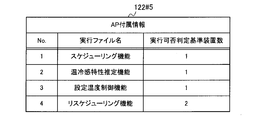
- FIG. 16 is a schematic diagram illustrating an example of AP attached information in the fifth embodiment.
- FIG. 16 is a schematic diagram illustrating an example of execution responsibility assignment information in the fifth embodiment.
- FIG. 1 is a schematic diagram of an information processing system 100 according to the first embodiment.
- the information processing system 100 includes a plurality of information processing apparatuses 110A to 110D, and distributes and executes an application (hereinafter referred to as AP) having a plurality of execution files.
- AP application
- the information processing apparatus 110 is connected to a LAN 101 as a network, and data communication is possible between a plurality of information processing apparatuses 110.
- the LAN 101 is a local area network built in a home and may or may not be connected to the Internet.
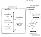
- the hardware configuration of the information processing device 110 includes a processor such as a CPU 10, a network communication device 11, a storage device such as a RAM (Random Access memory) 12 and a flash memory 13, and an input.
- a device 14 and a bus 15 are provided.
- the CPU 10 expands the AP in the RAM 12 and executes it.
- the network communication device 11 performs data communication with the information processing device 110 via the LAN 101.
- the RAM 12 is a volatile memory that is accessed by the CPU 10.
- the flash memory 13 is a non-volatile memory that stores the AP.
- the input device 14 receives an instruction from the user. For example, the input device 14 receives an input of a start setting start request as an AP execution instruction from the user. Specifically, the input device 14 includes a button or a remote control light receiving unit.
- the bus 15 connects the CPU 10, the network communication device 11, the RAM 12, the flash memory 13, and the input device 14, and enables transmission / reception of data in the connected portion.
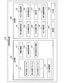
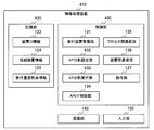
- FIG. 2 is a block diagram schematically showing a functional configuration of the information processing apparatus 110 according to the first embodiment.
- the information processing apparatus 110 includes a storage unit 120, a control unit 130, a communication unit 140, and an input unit 150.
- the storage unit 120 stores information and programs necessary for processing of the information processing apparatus 110.
- the storage unit 120 stores AP 121, AP attached information 122, device ID information 123, connection device information 124, and execution responsibility assignment information 125.
- the AP 121 is composed of a plurality of execution files.
- the execution file is a file that the CPU 10 can directly read into the RAM 12 and execute.
- the AP 121 includes a plurality of execution files obtained by converting a program written in a high-level language such as C language or Java language into an execution format.
- the AP 121 realizes one or a plurality of functions when a plurality of execution files operate in cooperation.
- HEMS Home Energy Management System
- HEMS has a function of acquiring and displaying the operating state of home appliances, a function of automatically driving according to a life schedule, and the like. These functions are realized by executing execution files such as a communication program, a display program, a schedule program, a device management program, and an operation management program.
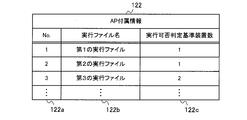
- the AP attached information 122 indicates an execution file that constitutes the AP 121 and an execution condition for executing the execution file.
- FIG. 3 is a schematic diagram illustrating an example of the AP attached information 122.
- the AP attached information 122 is information in a table format having a No column 122a, an execution file name column 122b, and an execution availability determination reference device number column 122c.
- the No column 122a stores an identification number for identifying each row included in the AP attached information 122.
- the executable file name column 122b stores an executable file name as executable file identification information for identifying the executable file constituting the AP 121.
- the executability determination reference device number column 122c stores the executability determination reference device number that is a condition for executing the execution file.
- the execution possibility determination reference device number is the number of devices necessary for executing the execution file. For example, when the number of information processing apparatuses 110 connected to the LAN 101 is equal to or greater than the number of execution permission determination reference apparatuses, the corresponding execution file can be executed.
- the AP 121 and the AP attached information 122 are stored in advance in the flash memory 13, for example.
- the device ID information 123 indicates a device ID that is device identification information of the information processing device 110 itself.
- the device ID may be, for example, an IP (Internet Protocol) address or a MAC (Media Access Control) address.
- the device ID may be unique identification information generated by a predetermined algorithm.
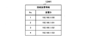
- the connection device information 124 indicates the device ID of the information processing device 110 connected to the LAN 101.
- FIG. 4 is a schematic diagram illustrating an example of the connection device information 124.
- the connection device information 124 is information in a table format having a No column 124a and a device ID column 124b.
- the No column 124 a stores an identification number for identifying each row included in the connection device information 124.
- the device ID column 124b stores the device ID of the information processing device 110 connected to the LAN 101.
- the connection device information 124 is stored in the RAM 12 or the flash memory 13.
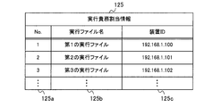
- the execution responsibility assignment information 125 indicates the information processing apparatus 110 having the responsibility to execute for each execution file.
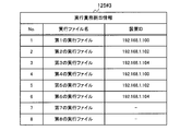
- FIG. 5 is a schematic diagram illustrating an example of the execution responsibility assignment information 125.
- the execution responsibility assignment information 125 is information in a table format having a No column 125a, an execution file name column 125b, and a device ID column 125c.
- the No column 125 a stores an identification number for identifying each row included in the execution responsibility assignment information 125.
- the execution file name column 125b stores the execution file names of the execution files that constitute the AP 121.
- the device ID column 125c stores the device ID of the information processing device 110 that is responsible for executing the execution file identified by the execution file name column 125b.
- the execution responsibility assignment information 125 is stored in the RAM 12 or the flash memory 13.
- the execution responsibility assignment information 125 is generated by the own device and stored in the storage unit 120, and is generated and transmitted by the other information processing device 110, and is received by the communication unit 140. May be stored in the storage unit 120.
- the execution responsibility assignment information 125 generated by the own apparatus and stored in the storage unit 120 is referred to as first execution responsibility assignment information, and is generated by another information processing apparatus 110 and stored in the storage unit 120.
- the execution responsibility assignment information 125 may be referred to as second execution responsibility assignment information.
- control unit 130 controls the processing of the information processing apparatus 110.
- the control unit 130 includes an execution device management unit 131, an AP division setting unit 132, an AP division execution unit 133, an AP interface control unit (hereinafter referred to as API / F control unit) 134, an inter-process communication unit 135, An inter-device communication unit 136 and an operation unit 137 are provided.
- API / F control unit AP interface control unit
- the execution apparatus management unit 131 acquires the apparatus ID of the own apparatus, and stores the apparatus ID information 123 indicating the acquired apparatus ID in the storage unit 120.
- the execution device management unit 131 detects the information processing device 110 connected to the LAN 101 and acquires a unique device ID held by each information processing device 110. Then, the execution device management unit 131 generates connection device information 124 as shown in FIG. 4 and stores it in the storage unit 120.
- the connection device information 124 includes the device ID of the own device indicated by the device ID information 123.
- the AP division setting unit 132 sets the execution duties of each of the plurality of execution files included in the AP to a plurality of pieces of information constituting the information processing system 100. Assign to any of the processing devices 110. For example, the AP division setting unit 132 determines whether or not an executable file with the executable file name written in the AP attached information 122 is executable, and the execution responsibility of the executable file determined to be executable is registered in the connection device information 124. Assigned to the existing information processing apparatus 110. Then, as shown in FIG. 5, the AP division setting unit 132 generates execution responsibility assignment information 125 indicating the execution file and the information processing apparatus 110 to which the execution responsibility of the execution file is assigned.
- the first execution file is executed by the information processing apparatus 110 having the apparatus ID 192.168.1.100
- the second execution file is the apparatus
- the third execution file is executed by the information processing apparatus 110 having the device ID 192.168.1.102, and is executed by the information processing apparatus 110 having the ID 192.168.1.101.
- the AP division execution unit 133 refers to the execution responsibility assignment information 125, acquires the execution file assigned to the own device from the flash memory 13, and executes it.
- the API / F control unit 134 determines the information processing apparatus 110 that is executing another executable file when a process execution request for the other executable file is generated during the processing of the executable file being executed. If the information processing apparatus 110 that is executing another execution file is its own apparatus, the API / F control unit 134 sends a process request to the other execution file via the inter-process communication unit 135. Send communication request. If the information processing apparatus 110 that is executing another execution file is another information processing apparatus 110, the API / F control unit 134 transmits another information processing apparatus via the inter-device communication unit 136 and the communication unit 140. An inter-device communication request that is a process execution request is transmitted to 110.
- the inter-process communication unit 135 transmits / receives data between executable files executed by the same information processing apparatus 110. For example, there is a method of using a message queue or shared memory supported by an OS (Operating System) as data transmission / reception for inter-process communication.
- OS Operating System
- the inter-device communication unit 136 performs data transmission / reception between execution files executed by other information processing apparatuses 110 via the communication unit 140.
- data transmission / reception for inter-device communication there is a method of using a network socket supported by the OS.
- the operation unit 137 detects an instruction input to the input unit 150. For example, the operation unit 137 detects a button press if the input device 14 functioning as the input unit 150 is a button, and detects a remote control signal if the input device 14 is a remote control light receiving unit. When the information processing apparatus 110 does not include the input device 14, the operation unit 137 detects an AP activation setting start command received by the network communication device 11 that functions as the communication unit 140. By detecting these, the operation unit 137 receives an AP activation setting start operation from the user.
- the communication unit 140 communicates with another information processing apparatus 110 via the LAN 101.
- the communication unit 140 functions as a transmission unit that transmits information to the LAN 101 and a reception unit that receives information from the LAN 101.
- the input unit 150 receives an instruction input from the user.
- the input unit 150 receives an input of an AP execution instruction.
- the storage unit 120 of the information processing apparatus 110 described above can be realized by the CPU 10 illustrated in FIG. 1 using the RAM 12 or the flash memory 13.
- the control unit 130 can be realized by the CPU 10 reading the program stored in the flash memory 13 into the RAM 12 and executing it.
- the communication unit 140 can be realized by the CPU 10 using the network communication device 11.
- the input unit 150 can be realized by the CPU 10 using the input device 14.
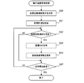
- FIG. 6 is a flowchart showing an overall processing procedure of the information processing apparatus 110 according to the first embodiment.
- the main processing after the information processing apparatus 110 is activated will be described with reference to FIG.
- the execution device management unit 131 When the information processing device 110 is activated, the execution device management unit 131 acquires a device ID unique to the information processing device 110 that is the device itself, and generates device ID information 123 indicating the acquired device ID. Then, the execution device management unit 131 stores the generated device ID information 123 in the storage unit 120 (S10). For example, when the device ID is an IP address or a MAC address, the execution device management unit 131 can acquire the device ID from the communication unit 140.
- the execution device management unit 131 uses a broadcast notification means such as multicast to the information processing device 110 connected to the LAN 101 to notify the communication unit 140 of the activation notification together with the device ID acquired in step S10. Transmit (S11).
- the control unit 130 waits for the activation setting start operation of the AP 121 from the user (S12), waits for the reception of the AP division execution request from the other information processing apparatus 110 (S16), and other information.
- the system waits for an apparatus activation confirmation request from the processing apparatus 110 (S18).
- step S12 when the operation unit 137 detects an input of a start setting start operation of the AP 121 from the user (YES in S12), the process proceeds to step S13.
- step S13 the execution device management unit 131 performs execution device management processing.
- the execution apparatus management unit 131 causes the communication unit 140 to transmit an apparatus activation confirmation request to the information processing apparatus 110 connected to the LAN 101, and an activation notification from the information processing apparatus 110 that has received the apparatus activation confirmation request.
- the execution device management unit 131 detects the information processing device 110 connected to the LAN 101 and generates connection device information 124 indicating the device ID of the detected information processing device 110.
- the AP division setting unit 132 performs AP division setting processing (S14).
- the AP division setting unit 132 determines whether or not the executable file can be executed, and assigns the execution responsibility of the executable file determined to be executable to any of the information processing apparatuses 110 detected in step S13.
- the responsibility assignment information 125 is generated and stored in the storage unit 120.
- the AP division setting unit 132 causes the communication unit 140 to transmit an AP division execution request together with the generated execution responsibility assignment information 125 to all the information processing apparatuses 110 detected in step S13.
- the AP division execution unit 133 performs AP division execution processing (S15).
- the AP division execution unit 133 refers to the execution responsibility assignment information 125 stored in the storage unit 120 and executes all the execution files assigned to the own device (S15).
- the information processing apparatus 110 is executing the AP 121.
- step S13 and step S14 is executed only by the information processing apparatus 110 that has received an AP activation setting start operation from the user as a master apparatus.
- the information processing apparatus 110 other than the master apparatus refers to the execution responsibility assignment information 125 sent from the master apparatus as a slave apparatus, as shown in steps S16 to S18 and step S15 below.
- the executable file assigned to the own device is executed.
- step S16 when the communication unit 140 receives an AP division execution request from another information processing apparatus 110 as a master apparatus (Yes in S16), the process proceeds to step S17.
- step S ⁇ b> 17 the AP division execution unit 133 acquires the execution responsibility assignment information 125 transmitted together with the AP division execution request, and stores it in the storage unit 120. Then, the process proceeds to step S15.
- step S18 when the communication unit 140 receives a device activation confirmation request from another information processing device 110 as a master device (Yes in S18), the process proceeds to step S11, and the communication unit requests such a request. Is not received (No in S18), the process proceeds to step S12.
- FIG. 7 is a flowchart showing the execution device management process performed in step S13 of FIG.
- the execution device management unit 131 causes the communication unit 140 to transmit a device activation confirmation request to the information processing device 110 connected to the LAN 101 using a broadcast notification unit such as multicast ( S20).
- a broadcast notification unit such as multicast
- the execution device management unit 131 initializes the connection device information 124 and deletes all rows, and then uses the device ID information 123.
- the device ID of the device shown is stored in the connection device information 124. If the connection device information 124 is not stored in the storage unit 120, the execution device management unit 131 generates the connection device information 124 that stores the device ID of the own device indicated by the device ID information 123.
- the storage unit 120 stores it.
- the execution device management unit 131 starts time measurement (S21) and confirms reception of the activation notification from the other information processing device 110 (S22).
- step S22 if the communication unit 140 has received the activation notification (Yes in S22), the process proceeds to step S23. If the communication unit 140 has not received the activation notification (No in S22), the process proceeds to step S23. Proceed to S25.
- step S23 the execution device management unit 131 acquires the device ID transmitted together with the activation notification. Then, the execution device management unit 131 updates the connection device information 124 by storing the device ID acquired in step S23 in the connection device information 124.
- step S25 the execution device management unit 131 determines whether or not a predetermined time has elapsed. When the predetermined time has elapsed (Yes in S25), the execution device management unit 131 ends the execution device management process. If the predetermined time has not elapsed (No in S25), the process proceeds to step S22. As described above, the execution device management unit 131 performs execution device management processing for a certain period of time to detect the information processing device 110 connected to the LAN 101.
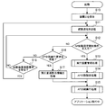
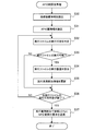
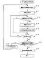
- FIG. 8 is a flowchart showing the AP division setting process performed in step S14 of FIG.
- the AP division setting unit 132 reads the connection device information 124 and the AP attached information 122 from the storage unit 120 (S30, S31).
- the AP division setting unit 132 generates, in the storage unit 120, the execution responsibility assignment information 125 in the initial state where the execution responsibility of the execution file is not assigned to the information processing apparatus 110, and stores it in the storage unit 120.
- the AP division setting unit 132 identifies one executable file that has not yet been determined to be executable among the executable files stored in the AP attached information 122, and determines whether or not the identified executable file is executable. (S32).
- the connection device information 124 read in step S30 is the connection device information 124 # 1 shown in FIG. 9, and the AP attached information 122 read in step S31 is shown in FIG.
- the AP division setting unit 132 determines that each of the first to seventh execution files is executable, and determines that the eighth execution file is not executable. If it is determined that the specified executable file can be executed (Yes in S33), the process proceeds to step S34, and if it is determined that the specified executable file cannot be executed (No in S33). The process proceeds to step S36.
- step S ⁇ b> 34 the AP division setting unit 132 assigns the execution responsibility of the executable file determined to be executable to one of the information processing apparatuses 110. For example, the AP division setting unit 132 selects the information processing device 110 that executes the execution file determined to be executable from the information processing devices 110 identified by the device ID stored in the connection device information 124. Thus, the execution responsibility of the execution file is assigned to the selected information processing apparatus 110. For example, when the information processing apparatus 110 is already allocated to the execution file, the AP division setting unit 132 executes the execution responsibility allocation information 125 so that the processing loads of the information processing apparatuses 110 are equalized. The information processing apparatus 110 with a small allocation of execution responsibilities is preferentially selected.
- the AP division setting unit 132 selects in order from the information processing apparatus 110 with the smallest number of execution duties assigned so that the number of execution duties assigned becomes equal. When the number of execution responsibilities assigned is the same, the AP division setting unit 132 selects the execution responsibilities assigned in ascending order of identification numbers stored in the No column 124a of the connected device information 124, for example. Any information processing device 110 may be selected from the information processing devices 110 having the same number. When the information processing apparatus 110 is not yet assigned to the execution file, the AP division setting unit 132 arbitrarily selects the information processing apparatus 110 from the information processing apparatuses 110 registered in the connection apparatus information 124. To do. In this case, the AP division setting unit 132 may select any information processing apparatus 110, for example, by selecting in order from the smallest identification number stored in the No column 124a of the connection apparatus information 124.
- the AP division setting unit 132 stores the device ID of the information processing apparatus 110 to which the execution duties are assigned in the execution duty assignment information 125 in association with the specified execution file. Then, the execution responsibility assignment information 125 is updated (S35).
- step S36 the AP division setting unit 132 determines whether or not execution of all the executable files has been determined. If there is an executable file that has not yet been determined to be executable (No in S36), the process proceeds to step S32, and if it is determined that all the executable files are executable (Yes in S36). ), The process proceeds to step S37.
- step 37 the AP division setting unit 132 sends an AP division execution request together with the execution responsibility assignment information 125 to the information processing device 110 identified by the device ID registered in the connection device information 124. Send it. Then, the AP division setting process ends.
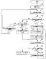
- FIG. 11 is a flowchart showing the AP division execution process performed in step S15 of FIG.
- the AP division execution unit 133 reads the execution responsibility assignment information 125 from the storage unit 120 (S40).
- the AP division execution unit 133 identifies one of the execution files included in the read execution responsibility assignment information 125 and has not yet been determined whether or not there is an execution responsibility. It is determined whether or not the own apparatus has an execution responsibility for the executed file (S41). For example, the AP division execution unit 133 compares the device ID indicated by the device ID information 123 stored in the storage unit 120 with the device ID corresponding to the execution file identified from the execution responsibility assignment information 125. If the device IDs match, it is determined that the specified execution file has the responsibility for execution. For example, the execution responsibility assignment information 125 read from the storage unit 120 is the execution responsibility assignment information 125 # 1 shown in FIG.
- the AP division execution unit 133 determines that there is an execution responsibility for the first execution file and the fifth execution file. In FIG. 12, the information processing apparatus 110 has no execution responsibility for the eighth execution file because the corresponding apparatus ID is indefinite.
- step S42 If it is determined that there is an execution responsibility for the identified executable file (Yes in S42), the process proceeds to step S43, and if it is determined that there is no execution responsibility for the identified executable file (No in S42). The process proceeds to step S44.
- step S43 the AP division execution unit 133 acquires the specified execution file from the AP 121 of the storage unit 120 and executes it. Then, the process proceeds to step S44.
- step S44 the AP division execution unit 133 determines whether or not the determination of whether or not there is an execution responsibility has been completed for all execution files included in the read execution responsibility assignment information 125. If there is an execution file that has not yet been determined whether or not there is an execution responsibility (No in S44), the process proceeds to step S41. (Yes in S44), the AP division execution process ends.
- the inter-execution file communication process of the API / F control unit 134 will be described with reference to FIGS. 13 and 14.
- communication processing between the first execution file and the second execution file is taken as an example, but all execution files can be communicated by the same communication processing.
- FIG. 13 is a flowchart showing the processing of the first executable file.
- the AP division execution unit 133 requests execution of the B001 function of the second execution file, for example, in the processing of the first execution file (S50).
- the API / F control unit 134 reads the device ID information 123 and the execution responsibility assignment information 125 from the storage unit 120 (S51).
- the API / F control unit 134 refers to the read device ID information 123 and execution responsibility assignment information 125 to determine whether or not the own device has the execution responsibility of the second execution file (S52). ). For example, the API / F control unit 134 compares the device ID indicated by the device ID information 123 with the device ID corresponding to the second execution file acquired from the execution responsibility assignment information 125, and the device ID is determined. If they match, the device having the execution responsibility of the second execution file is the same as the device having the execution responsibility of the first execution file. In other words, it is determined that the device has the execution responsibility of the second execution file. To do. If the own apparatus has the execution responsibility for the second executable file (Yes in S53), the process proceeds to step S54, and if the other information processing apparatus 110 has the execution obligation for the second execution file ( The process proceeds to step S57.
- step S54 the API / F control unit 134 transmits an execution request for the B001 function to the second execution file via the inter-process communication unit 135 (S54).
- the API / F control unit 134 waits for the B001 function calculation result, and when the B001 function of the second execution file is executed, the B001 function is transmitted via the inter-process communication unit 135. A value is received as a function calculation result (S55).
- the API / F control unit 134 gives the calculation result of the B001 function received from the inter-process communication unit 135 to the AP division execution unit 133, whereby the AP division execution unit 133 acquires the calculation result of the B001 function (S56). ).
- step S53 If it is determined in step S53 that the other information processing apparatus 110 is responsible for executing the second executable file (No in S53), the process proceeds to step S57.
- step S57 the API / F control unit 134 acquires the device ID corresponding to the second execution file from the execution responsibility assignment information 125. Then, the API / F control unit 134 sends an inter-device communication request that is an execution request for the B001 function to the information processing device 110 that is responsible for executing the second execution file, via the inter-device communication unit 136. Is transmitted (S58).
- the API / F control unit 134 When the API / F control unit 134 transmits an execution request for the B001 function, the API / F control unit 134 waits for the calculation result of the B001 function. When the B001 function of the second execution file is executed, the API / F control unit 134 passes the communication unit 140 and the inter-device communication unit 136. Then, the value as the calculation result of the B001 function is received (S59). Then, the process proceeds to step S56.
- FIG. 14 is a flowchart showing processing of the second executable file.
- the API / F control unit 134 waits for a function execution request from another execution file via the inter-process communication unit 135 ( S61) and a function execution request from another execution file via the communication unit 140 and the inter-device communication unit 136 are waited (S63).
- step S62 the API / F control unit 134 sets an inter-process communication flag in the storage unit 120.
- step S64 the API / F control unit 134 causes the AP division execution unit 133 to execute the B001 function (S64). Then, the process proceeds to step S65.
- step S65 the API / F control unit 134 determines whether or not the inter-process communication flag is set. If the inter-process communication flag is set (Yes in S65), the process proceeds to step S66. If the inter-process communication flag is not set (No in S65), the process proceeds to step S67.
- step S66 the API / F control unit 134 transmits the calculation result of the B001 function to the first execution file via the inter-process communication unit 135.
- step S67 the API / F control unit 134 transmits the calculation result of the B001 function to the information processing apparatus 110 having the responsibility for executing the first execution file to the communication unit 140 via the inter-device communication unit 136.
- the information processing apparatus 110 having the responsibility for executing the first executable file is also referred to as a first information processing apparatus
- the information processing apparatus 110 having the execution responsibility for the second execution file is also referred to as a second information processing apparatus.
- the information processing apparatus 110 having the responsibility for executing the first executable file is the same as the information processing apparatus 110 having the responsibility for executing the second execution file
- the execution of the first execution file and the second execution file is executed.
- the information processing apparatus having the responsibility is also referred to as a first information processing apparatus.
- the information processing apparatus 110 serving as the master apparatus assigns the execution responsibility of the execution file constituting the AP to the information processing apparatus 110 connected to the LAN 101.
- Each information processing apparatus 110 can execute APs in a distributed manner without causing overhead due to the distributed processing by executing only the assigned execution file. Therefore, even in the device cooperation system configured with the information processing apparatus 110 equipped with a low-performance CPU, an immediate response to apparatus operation and real-time information display are possible.
- the device cooperation system can be realized without the processing at the AP failing.
- the information processing system 200 includes a plurality of information processing apparatuses 210A to 210D.
- the information processing apparatus 210 when it is not necessary to distinguish each of the information processing apparatuses 210A to 210D, they are referred to as the information processing apparatus 210.
- the hardware configuration of the information processing apparatus 210 in the second embodiment is the same as the hardware configuration of the information processing apparatus 110 in the first embodiment shown in FIG.
- FIG. 15 is a block diagram schematically showing a functional configuration of the information processing apparatus 210 according to the second embodiment.
- the information processing apparatus 210 includes a storage unit 120, a control unit 230, a communication unit 140, and an input unit 150.
- the information processing apparatus 210 in the second embodiment is configured in the same manner as the information processing apparatus 110 in the first embodiment except for the control unit 230.
- the control unit 230 controls processing of the information processing apparatus 210.
- the control unit 230 includes an execution device management unit 131, an AP division setting unit 232, an AP division execution unit 233, an API / F control unit 134, an inter-process communication unit 135, an inter-device communication unit 136, and an operation unit. 137 and an execution device monitoring unit 238.
- the control unit 230 in the second embodiment is configured similarly to the control unit 130 in the first embodiment except for the AP division setting unit 232, the AP division execution unit 233, and the execution device monitoring unit 238.
- the AP division setting unit 232 determines whether or not the executable file having the executable file name written in the AP attached information 122 can be executed, and information on the execution responsibility of the executable file determined to be executable is registered in the connection device information 124. Assigned to the processing device 210. When the information processing apparatus 210 is newly connected to the LAN 101 after assigning the execution responsibility of the execution file to the information processing apparatus 210, the AP division setting unit 232 according to the second embodiment assigns the execution responsibility of the execution file again. .
- the AP division execution unit 233 refers to the execution responsibility assignment information 125, acquires the execution file with the execution responsibility assigned to the own apparatus from the flash memory 13, and executes it.
- the AP division execution unit 233 according to the second embodiment executes the newly assigned execution file when the execution responsibility of the execution file is newly assigned during execution of the execution file assigned to the own device. .
- the execution device monitoring unit 238 detects the information processing device 210 newly connected to the LAN 101 during AP execution, acquires a unique device ID held by the newly connected information processing device 210, and connects to the connection device information 124. Update.
- the master device in other words, the execution device monitoring unit 238 of the information processing device 210 that has received the AP activation setting start operation from the user performs the processing as described above.
- FIG. 16 is a flowchart illustrating an overall processing procedure of the information processing apparatus 210 according to the second embodiment.
- the same processes as those shown in FIG. 6 are denoted by the same reference numerals as those in FIG.
- steps S10 to S13 and steps S16 to S18 in FIG. 16 are the same as those in FIG. However, after step S13, the process proceeds to step S70, and after step S17, the process proceeds to step S72.
- step S70 the AP division setting unit 232 performs AP division setting processing. Details of the processing here will be described with reference to FIG. Next, the execution device monitoring unit 238 sets a master device flag in the storage unit 120 (S71).
- the AP division execution unit 233 performs AP division execution processing (S72). Details of the processing here will be described with reference to FIG. Next, the execution device monitoring unit 238 determines whether or not a master device flag is set in the storage unit 120 (S73). If the master device flag is set (Yes in S73), the process proceeds to step S74. If the master device flag is not set (No in S73), the AP is being executed.
- step S74 the execution device monitoring unit 238 performs execution device addition monitoring processing.
- the process proceeds to step S70, and the AP division setting process is performed again.
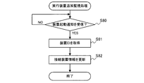
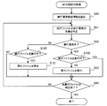
- FIG. 17 is a flowchart showing the execution device addition monitoring process performed in step S74 of FIG.
- the execution device monitoring unit 238 checks whether or not the communication unit 140 has received a startup notification that the information processing device 210 notifies when starting up (S80). In other words, the execution device monitoring unit 238 checks whether or not an activation notification has been received after the execution device management process in step S13. Thereby, the information processing apparatus 210 newly connected to the LAN 101 can be detected. If an activation notification has been received (Yes in S80), the process proceeds to step S81.
- step S81 the execution device monitoring unit 238 acquires the device ID transmitted together with the activation notification.
- the execution device monitoring unit 238 updates the connection device information 124 by storing the acquired device ID in the connection device information 124 (S82). For example, when the device ID “192.168.1.104” of the newly connected information processing device 210 is added to the connection device information 124 # 1 shown in FIG. 9, the connection device information 124 # 1. Is updated to the connection device information 124 # 2 shown in FIG.
- FIG. 19 is a flowchart showing the AP division setting process performed in step S70 of FIG. Of the processes shown in FIG. 19, the same processes as those shown in FIG. 8 are denoted by the same reference numerals as those in FIG.
- steps S30 to S33 and steps S34 to S37 in FIG. 19 are the same as the processes having the same reference numerals in FIG. However, after step S33, the process proceeds to step S90.
- step S ⁇ b> 90 the AP division setting unit 232 reads the execution responsibility assignment information 125 from the storage unit 120.
- the AP division setting unit 232 determines whether or not an execution responsibility has already been assigned to the specified execution file (S91). For example, in the case of the execution responsibility assignment information 125 # 1 shown in FIG. 12, it is determined that the first execution file to the seventh execution file have already been assigned, but the eighth execution file Is determined not to be assigned. If the execution responsibility has already been assigned (Yes in S91), the process proceeds to step S36. If the execution responsibility has not been assigned, the process proceeds to step S34.
- step S ⁇ b> 34 the AP division setting unit 232 assigns the execution responsibility of the identified execution file to any of the information processing apparatuses 210 connected to the LAN 101.
- the assignment method here is the same as in the first embodiment. For example, when the execution responsibility of the eighth execution file is assigned in the execution responsibility assignment information 125 # 1 shown in FIG. 12, the execution responsibility assignment information 125 # 1 is changed to the execution responsibility as shown in FIG. The allocation information is updated to 125 # 2 (S35).
- FIG. 21 is a flowchart showing the AP division execution process performed in step S72 of FIG. Of the processes shown in FIG. 21, the same processes as those shown in FIG. 11 are denoted by the same reference numerals as those in FIG.
- steps S40 to S44 in FIG. 21 is the same as the processing in FIG. However, if it is determined in step S42 in FIG. 21 that there is an execution responsibility for the specified executable file (Yes in S42), the process proceeds to step S100.
- step S100 the AP division execution unit 233 determines whether the specified execution file has already been executed. If the specified executable file has already been executed (Yes in S100), the process proceeds to step S44. If the specified executable file is not executed (No in S100), the process proceeds to step S43.
- the execution file execution determination is performed again, and if it is determined to be executable, the execution responsibility is assigned and executed. .
- the execution responsibility of this execution file is changed. Is assigned to the information processing apparatus 210, and this executable file is executed.
- the information processing apparatus 210 newly connected to the LAN 101 is detected, and can be executed because the number of information processing apparatuses 210 connected to the LAN 101 is small. By making it possible to execute an executable file that did not exist later, user convenience can be improved.
- the information processing system 300 includes a plurality of information processing devices 310A to 310D.
- the information processing apparatus 310 when it is not necessary to distinguish each of the information processing apparatuses 310A to 310D, they are referred to as the information processing apparatus 310.
- the hardware configuration of the information processing apparatus 310 in the third embodiment is the same as the hardware configuration of the information processing apparatus 110 in the first embodiment shown in FIG.
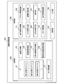
- FIG. 22 is a block diagram schematically showing a functional configuration of the information processing apparatus 310 according to the third embodiment.
- the information processing apparatus 310 includes a storage unit 320, a control unit 330, a communication unit 140, and an input unit 150.
- the information processing apparatus 310 in the third embodiment is configured in the same manner as the information processing apparatus 110 in the first embodiment except for the storage unit 320 and the control unit 330.
- the storage unit 320 stores information and programs necessary for processing of the information processing apparatus 310.
- the storage unit 320 stores the AP 121, AP attached information 122, device ID information 123, connection device information 124, execution responsibility assignment information 125, and monitoring connection device information 326.
- the storage unit 320 in the third embodiment stores the same information and program as the storage unit 120 in the first embodiment, except for the monitoring connection device information 326.
- the monitoring connection device information 326 indicates the device ID of the information processing device 310 connected to the LAN 101.
- FIG. 23 is a schematic diagram illustrating an example of the monitoring connection device information 326. As shown in the figure, the monitoring connection device information 326 is information in a table format having a No column 326a and a device ID column 326b.
- the No column 326a stores an identification number for identifying each row included in the monitoring connection device information 326.
- the device ID column 326b stores the device ID of the information processing device 310 connected to the LAN 101.
- the control unit 330 controls processing of the information processing device 310.
- the control unit 330 includes an execution device management unit 131, an AP division setting unit 232, an AP division execution unit 333, an API / F control unit 134, an inter-process communication unit 135, an inter-device communication unit 136, and an operation unit. 137 and an execution device monitoring unit 338.
- the control unit 330 in the third embodiment is configured in the same manner as the control unit 230 in the second embodiment except for the AP division execution unit 333 and the execution device monitoring unit 338.
- the AP division setting unit 232 performs the same processing as in the second embodiment.
- the execution device monitoring unit 338 detects the information processing device 310 newly connected to the LAN 101 during execution of the AP, acquires a unique device ID held by the newly connected information processing device 310, and connects to the connection device information 124. Update.
- the execution device monitoring unit 338 updates the connection device information 124 by detecting the information processing device 310 that is no longer connected to the LAN 101, for example, when communication becomes impossible due to an error.
- the execution device monitoring unit 338 updates the connection device information 124 using the monitoring connection device information 326.
- the master device in other words, the execution device monitoring unit 338 of the information processing device 310 that has received the AP activation setting start operation from the user performs the above-described processing.
- the AP division execution unit 333 refers to the execution responsibility assignment information 125, acquires the execution file in which the execution responsibility is assigned to the own apparatus from the flash memory 13, and executes it. In the third embodiment, the AP division execution unit 333 executes the newly assigned execution file when the execution responsibility of the execution file is newly assigned during execution of the execution file assigned to the own device. . In addition, when the assignment of execution responsibility to the own device is withdrawn, the AP division execution unit 333 stops the execution of the execution file with which the assignment of execution responsibility has been withdrawn.
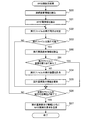
- FIG. 24 is a flowchart showing execution device addition monitoring processing of the execution device monitoring unit 338 according to the third embodiment.
- the execution device monitoring unit 338 causes the communication unit 140 to transmit a device activation confirmation request to the information processing device 310 connected to the LAN 101 using a broadcast notification unit such as multicast. (S110).
- the execution device monitoring unit 338 initializes the monitoring connection device information 326, deletes all rows, and then deletes the device.
- the device ID of the own device indicated by the ID information 123 is stored in the monitoring connection device information 326. If the monitoring connection device information 326 is not stored in the storage unit 320, the execution device monitoring unit 338 uses the monitoring connection device information 326 that stores the device ID of the own device indicated by the device ID information 123. It is generated and stored in the storage unit 320.
- the execution device monitoring unit 338 starts time measurement (S111).
- the execution device monitoring unit 338 confirms whether the communication unit 140 has received a startup notification that the information processing device 310 notifies when starting up (S112). If the activation notification has been received (Yes in S112), the process proceeds to step S113. If the activation notification has not been received (No in S112), the process proceeds to step S115.
- step S113 the execution device monitoring unit 338 acquires the device ID transmitted together with the activation notification.
- the execution device monitoring unit 338 updates the monitoring connection device information 326 by storing the acquired device ID in the monitoring connection device information 326 (S114).
- step S115 the execution device monitoring unit 338 determines whether or not a certain time has elapsed since the measurement was started in step S111 (S115). If the predetermined time has elapsed (Yes in S115), the process proceeds to step S116. If the predetermined time has not elapsed (No in S115), the process proceeds to step S112.
- step S116 the execution device monitoring unit 338 compares the monitoring connection device information 326 and the connection device information 124 to determine whether there is a difference. For example, when the monitoring connection device information 326 shown in FIG. 23 is compared with the connection device information 124 # 1 shown in FIG. 9, the device ID “192.168.1.104” is added, The device ID “192.168.1.101” and the device ID “192.168.1.103” are deleted.
- step S117 since there is a difference between the monitoring connection device information 326 and the connection device information 124, the execution device monitoring unit 338 updates the connection device information 124 so that it matches the monitoring connection device information 326. Then, the execution device addition monitoring process ends.
- step S118 the execution device monitoring unit 338 waits for a certain period of time. Then, the process proceeds to step S110.
- the execution device monitoring unit 338 performs the execution device addition monitoring process at regular time intervals to detect addition and deletion of the device ID of the information processing device 310.
- FIG. 25 is a flowchart illustrating AP division execution processing performed by the AP division execution unit 333 according to the third embodiment.
- the same processes as those shown in FIG. 21 are denoted by the same reference numerals as those in FIG.
- steps S40 to S44 and step S100 shown in FIG. 25 are the same as the processes denoted by the same reference numerals in FIG. However, if it is determined in step S42 that there is no execution responsibility for the specified executable file (No in step S42), the process proceeds to step S120.
- step S120 the AP division execution unit 333 determines whether the specified execution file is being executed. If the identified executable file is being executed (Yes in step S120), the process proceeds to step S121. If the identified executable file is not being executed (No in S120), the process proceeds to step S44. Proceed to
- step S121 the AP division execution unit 333 stops the execution of the specified execution file. Then, the process proceeds to step S44.
- the execution device monitoring unit 338 updates the connection device information 124 so that the connection device information 124 # 2 shown in FIG. 18 becomes the same as the monitoring connection device information 326 shown in FIG.
- the AP division setting unit 232 updates the execution responsibility assignment information 125 # 5 shown in FIG. 20 to the execution responsibility assignment information 125 # 3 shown in FIG.
- the information processing apparatus 310 with the device ID of 192.168.1.100 stops the execution of the fifth execution file while executing the first execution file, and the fourth execution file is stored.
- the information processing apparatus 310 with the apparatus ID 192.168.1.102 stops the execution of the third execution file and the seventh execution file, and executes the second execution file and the fifth execution file.
- the information processing apparatus 310 with the apparatus ID 192.168.1.104 stops the execution of the eighth execution file and executes the third execution file and the sixth execution file.
- the information processing apparatus 310 is connected to the LAN 101 each time.
- the device cooperation system can be realized without the AP failing.
- FIG. 27 is a schematic diagram of an information processing system 400 according to the fourth embodiment.
- the information processing system 400 includes a plurality of information processing apparatuses 410A to 410D, a gateway (hereinafter referred to as GW) 470, and a cloud server 480.
- GW gateway
- the information processing apparatus 410 is connected to the LAN 101 as a network, and data communication is possible between the plurality of information processing apparatuses 410.
- the hardware configuration of the information processing apparatus 410 in the fourth embodiment is the same as the hardware configuration of the information processing apparatus 110 in the first embodiment.
- the GW 470 is connected to the LAN 101 and the Internet 102, and performs protocol conversion between them. Thereby, the information processing apparatus 410 can communicate with the cloud server 480 via the GW 470.
- the cloud server 480 is connected to the Internet 102, and the information processing apparatus 410 can receive information and programs from the cloud server 480 via the LAN 101, the GW 470, and the Internet 102.
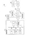
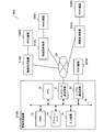
- FIG. 28 is a block diagram schematically showing a functional configuration of the information processing apparatus 410 according to the fourth embodiment.
- the information processing apparatus 410 includes a storage unit 420, a control unit 430, a communication unit 140, and an input unit 150.
- the information processing apparatus 410 in the fourth embodiment is configured in the same manner as the information processing apparatus 110 in the first embodiment except for the storage unit 420 and the control unit 430.
- the storage unit 420 stores information and programs necessary for processing of the information processing apparatus 410.
- the storage unit 420 stores device ID information 123, connection device information 124, and execution responsibility assignment information 125. These pieces of information are the same as the corresponding information in the first embodiment.
- the storage unit 420 in the fourth embodiment does not store the AP 121 and the AP attached information 122 stored in advance in the first embodiment. In the fourth embodiment, these are acquired from the cloud server 480.
- the control unit 430 controls processing of the information processing apparatus 410.
- the control unit 430 includes an execution device management unit 131, an AP division setting unit 432, an AP division execution unit 433, an API / F control unit 134, an inter-process communication unit 135, an inter-device communication unit 136, and an operation unit. 137.
- the control unit 430 in the fourth embodiment is configured similarly to the control unit 130 in the first embodiment except for the AP division setting unit 432 and the AP division execution unit 433.
- the AP division setting unit 432 acquires AP attached information from a predetermined location of the cloud server 480 via the communication unit 140.
- the acquired AP attached information is stored in the storage unit 420.
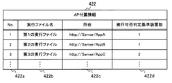
- FIG. 29 is a schematic diagram showing an example of AP attached information in the fourth embodiment.
- the AP attached information 422 is information in a table format having a No column 422a, an execution file name column 422b, a location column 422c, and an execution availability determination reference device number column 422d.
- the information stored in the No column 422a, the execution file name column 422b, and the execution possibility determination reference device number column 422d is the same as the information stored in the corresponding column of the AP attached information 122 in the first embodiment.
- the location column 422c stores information indicating the location of the execution file.
- a URL Uniform Resource Locator
- the AP ancillary information 422 in the fourth embodiment is information indicating the execution file that constitutes the AP, the location of the execution file, and the execution condition for executing the execution file.
- the AP division setting unit 432 determines whether or not the executable file with the executable file name written in the AP attached information 422 is executable, and the execution responsibility of the executable file determined to be executable is stored in the connection device information 124. Assigned to the registered information processing apparatus 410. Then, the AP division setting unit 432 generates the execution responsibility assignment information 125 and stores it in the storage unit 420.
- the AP division execution unit 433 refers to the execution responsibility assignment information 125 and the AP attached information 422, and acquires the execution file assigned to the own device from the cloud server 480 indicated by the location corresponding to the execution file.
- the acquired execution file is stored in the storage unit 420 and executed.
- the capacity of the flash memory 13 can be reduced by acquiring the AP execution file and the AP attached information 422 from the cloud server 480.
- the AP division setting unit 432 generates the execution responsibility assignment information 125 similar to that in the first embodiment, but the processing in the AP division setting unit 432 is limited to such an example.
- the AP division setting unit 432 may generate execution responsibility assignment information 425 as shown in FIG. 30 and store it in the storage unit 420.
- FIG. 30 is a schematic diagram illustrating an example of the execution responsibility assignment information 425.
- the execution responsibility assignment information 425 is information in a table format having a No column 425a, an execution file name column 425b, a location column 425c, and a device ID column 425d.
- Information stored in the No column 425a, the execution file name column 425b, and the device ID column 425d is the same as the information stored in the corresponding column of the execution responsibility assignment information 125 in the first embodiment.
- the location column 425c stores information indicating the location of the execution file.
- the execution responsibility assignment information 425 is information indicating the location of the execution file and the information processing apparatus 410 having the execution responsibility for each execution file.
- the AP division execution unit 433 refers to the execution responsibility assignment information 425, acquires the execution file assigned to the own apparatus from the cloud server 480 indicated by the location corresponding to the execution file, and executes the execution file. .
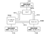
- FIG. 31 is a schematic diagram of an information processing system 500 according to the fifth embodiment.
- the information processing system 500 includes a plurality of information processing apparatuses 510A to 510D and a plurality of HEMS devices 590A to 590D.
- the information processing apparatus 510 is connected to a LAN 101 as a network, and data communication is possible between a plurality of information processing apparatuses 510.
- a HEMS device 590 when it is not necessary to particularly distinguish each of the HEMS devices 590A to 590D, it is referred to as a HEMS device 590.
- the hardware configuration of the information processing apparatus 510 in the fifth embodiment is the same as the hardware configuration of the information processing apparatus 110 in the first embodiment except that the serial communication device 16 is added.
- the serial communication device 16 performs serial communication with the HEMS device 590.
- the information processing device 510 is connected to the HEMS device 590 via the serial communication device 16.
- the information processing device 510 may be built in the HEMS device 590, or the information processing device 510 may be externally attached to the HEMS device 590.
- Each of the HEMS devices 590A to 590D is, for example, a household appliance such as a home TV, a refrigerator, or an IH cooking heater, an air conditioner such as an air conditioner, or a heat pump type hot / cold water system device.
- FIG. 32 is a block diagram schematically showing a functional configuration of the information processing apparatus 510 according to the fifth embodiment.
- the information processing apparatus 510 includes a storage unit 520, a control unit 530, a communication unit 140, an input unit 150, and a serial communication unit 560.
- the information processing apparatus 510 in the fifth embodiment is configured in the same manner as the information processing apparatus 110 in the first embodiment, except for the storage unit 520, the control unit 530, and the serial communication unit 560.
- the storage unit 520 stores information and programs necessary for processing of the information processing apparatus 510.
- the storage unit 520 stores the AP 121, AP attached information 122, device ID information 123, connection device information 124, execution responsibility assignment information 125, and resident AP 527.
- the storage unit 520 in the fifth embodiment stores the same information and program as the storage unit 120 in the first embodiment except for the resident AP 527.
- the resident AP 527 is composed of one or a plurality of execution files, and the information processing apparatus 510 always executes the resident AP 527 stored in the storage unit 520.
- the resident AP 527 is an application that is not distributed and executed.
- the resident AP 527 is an execution file that realizes a unique function of the information processing apparatus 510 or a control function of the HEMS device 590 connected via the serial communication apparatus 16.
- the control unit 530 controls processing of the information processing apparatus 510.
- the control unit 530 includes an execution device management unit 131, an AP division setting unit 132, an AP division execution unit 533, an API / F control unit 134, an inter-process communication unit 135, an inter-device communication unit 136, and an operation unit. 137.
- the control unit 530 in the fifth embodiment is configured in the same manner as the control unit 130 in the first embodiment except for the AP division execution unit 533.
- the AP division execution unit 533 acquires the execution file of the resident AP 527 from the flash memory 13 and executes it.
- the serial communication unit 560 performs serial communication with the HEMS device 590 and transmits / receives information.
- FIG. 33 is a schematic diagram showing a system configuration example in which the information processing apparatus 510 is applied to a heat pump type cold / hot water system.
- the HEMS device 590 constituting the heat pump type cold / hot water system, there are a heat pump unit 590A # for heating and supplying hot water, a radiator 590B # for radiating heat, and a valve 590C # for controlling the flow rate.
- Each of these HEMS devices 590 is connected to each of the information processing apparatuses 510.
- the heat pump unit 590A #, the radiator 590B #, and the valve 590C # are connected by pipes 591A to 591C.
- the room temperature optimum control AP of the heat pump type cold / hot water system is composed of, for example, an execution file indicated by AP attached information 122 # 5 in FIG. Then, the execution responsibility of each execution file is assigned to the information processing apparatuses 510A to 510C by the AP division setting unit 132, and, for example, execution responsibility assignment information 125 # 5 shown in FIG. 35 is generated.
- the resident AP 527 of the information processing apparatus 510A is, for example, an execution file that acquires the temperature information of the heat pump unit 590A # and sets the temperature.
- the resident AP 527 of the information processing apparatus 510B is an execution file that sets the operation mode of the radiator 590B #, for example.
- the resident AP 527 of the information processing apparatus 510C is an execution file that acquires temperature information of the valve 590C # and opens and closes the valve, for example.
- the execution operations of the AP 121 and the resident AP 527 of the information processing apparatus 510 in the heat pump type cold / hot water system are performed as follows.
- the AP division execution unit 533 of the information processing apparatus 510A executes an execution file for the scheduling function, an execution file for the rescheduling function, and an execution file for acquiring temperature information and setting the temperature of the heat pump unit 590A #.
- AP division execution unit 533 of information processing device 510B executes the execution file for the thermal sensation characteristic estimation function and the execution file for changing the operation mode of radiator 590B #.
- the AP division execution unit 533 of the information processing apparatus 510C executes an execution file for the set temperature control function and an execution file for acquiring temperature information of the valve 590C # and opening / closing the valve.
- the information processing apparatus 510 executes the execution file for controlling the connected HEMS device 590, so that the specific HEMS device 590 is executed even when the AP 121 is executed in a distributed manner. Can be controlled.
Landscapes
- Engineering & Computer Science (AREA)
- Software Systems (AREA)
- Theoretical Computer Science (AREA)
- Physics & Mathematics (AREA)
- General Engineering & Computer Science (AREA)
- General Physics & Mathematics (AREA)
- Computer Networks & Wireless Communication (AREA)
- Signal Processing (AREA)
- Computer And Data Communications (AREA)
- Information Retrieval, Db Structures And Fs Structures Therefor (AREA)
- Information Transfer Between Computers (AREA)
Abstract
Description
図1は、実施の形態1に係る情報処理システム100の概略図である。
情報処理システム100は、複数の情報処理装置110A~110Dにより構成されており、複数の実行ファイルを有するアプリケーション(以下、APという)を分散して実行する。ここで、情報処理装置110A~110Dの各々を特に区別する必要がない場合には、情報処理装置110という。情報処理装置110は、ネットワークとしてのLAN101に接続されており、複数の情報処理装置110間でデータ通信が可能となっている。なお、LAN101は、宅内に構築されるローカルエリアネットワークであって、インターネットに接続されていても、接続されていなくてもよい。
ネットワーク通信装置11は、LAN101を介して情報処理装置110と互いにデータ通信を行う。
RAM12は、CPU10がアクセスする揮発性メモリである。
フラッシュメモリ13は、APを格納する不揮発性メモリである。
入力装置14は、ユーザからの指示を受け付ける。例えば、入力装置14は、ユーザからのAPの実行指示としての起動設定開始要求の入力を受け付ける。具体的には、入力装置14は、ボタン又はリモコン受光部により構成される。
バス15は、CPU10、ネットワーク通信装置11、RAM12、フラッシュメモリ13及び入力装置14を接続し、接続された部分のデータの送受信を可能としている。
情報処理装置110は、記憶部120と、制御部130と、通信部140と、入力部150とを備える。
図3は、AP付属情報122の一例を示す概略図である。
図示するように、AP付属情報122は、No列122aと、実行ファイル名列122bと、実行可否判定基準装置数列122cとを有するテーブル形式の情報である。
No列122aは、AP付属情報122に含まれる各々の行を識別するための識別番号を格納する。
実行ファイル名列122bは、AP121を構成する実行ファイルを識別するための実行ファイル識別情報としての実行ファイル名を格納する。
実行可否判定基準装置数列122cは、実行ファイルを実行するための条件である実行可否判定基準装置数を格納する。実行可否判定基準装置数は、実行ファイルを実行するために必要な装置数である。例えば、LAN101に接続されている情報処理装置110の数が、実行可否判定基準装置数以上である場合に、対応する実行ファイルを実行することができるものとする。
なお、AP121及びAP付属情報122は、例えば、フラッシュメモリ13に予め格納されている。
図4は、接続装置情報124の一例を示す概略図である。
図示するように、接続装置情報124は、No列124aと、装置ID列124bとを有するテーブル形式の情報である。
No列124aは、接続装置情報124に含まれる各々の行を識別するための識別番号を格納する。
装置ID列124bは、LAN101に接続されている情報処理装置110の装置IDを格納する。
なお、接続装置情報124は、RAM12又はフラッシュメモリ13に記憶される。
図5は、実行責務割当情報125の一例を示す概略図である。
図示するように、実行責務割当情報125は、No列125aと、実行ファイル名列125bと、装置ID列125cとを有するテーブル形式の情報である。
No列125aは、実行責務割当情報125に含まれる各々の行を識別するための識別番号を格納する。
実行ファイル名列125bは、AP121を構成する実行ファイルの実行ファイル名を格納する。
装置ID列125cは、実行ファイル名列125bで識別される実行ファイルを実行する責務を有する情報処理装置110の装置IDを格納する。
ここで、実行責務割当情報125は、後述するように、自装置で生成されて記憶部120に記憶される場合と、他の情報処理装置110で生成及び送信され、通信部140が受信して、記憶部120に記憶される場合とがある。以下、自装置で生成されて記憶部120に記憶されている実行責務割当情報125を第1の実行責務割当情報といい、他の情報処理装置110で生成されて記憶部120に記憶されている実行責務割当情報125を第2の実行責務割当情報という場合がある。
制御部130は、実行装置管理部131と、AP分割設定部132と、AP分割実行部133と、APインターフェース制御部(以下、API/F制御部という)134と、プロセス間通信部135と、装置間通信部136と、操作部137とを備える。
また、実行装置管理部131は、LAN101に接続された情報処理装置110を検出し、各情報処理装置110が保持する固有の装置IDを取得する。そして、実行装置管理部131は、図4に示されているような接続装置情報124を生成して、それを記憶部120に記憶させる。なお、接続装置情報124には、装置ID情報123で示されている自装置の装置IDが含まれる。
そして、AP分割設定部132は、図5に示されているように、実行ファイルと、その実行ファイルの実行責務が割り当てられた情報処理装置110とを示す実行責務割当情報125を生成して、それを記憶部120に記憶させる。図5に示されている実行責務割当情報125の場合では、第1の実行ファイルは、装置IDが192.168.1.100の情報処理装置110で実行され、第2の実行ファイルは、装置IDが192.168.1.101の情報処理装置110で実行され、第3の実行ファイルは、装置IDが192.168.1.102の情報処理装置110で実行されることになる。
情報処理装置110が入力装置14を備えていない場合には、操作部137は、通信部140として機能するネットワーク通信装置11で受信するAP起動設定開始コマンドを検出する。操作部137は、これらを検出することによって、ユーザからのAPの起動設定開始操作を受け付ける。
入力部150は、ユーザからの指示の入力を受け付ける。例えば、入力部150は、APの実行指示の入力を受け付ける。
制御部130は、CPU10が、フラッシュメモリ13に記憶されているプログラムをRAM12に読み出して、それを実行することで、実現することができる。
通信部140は、CPU10が、ネットワーク通信装置11を利用することにより実現することができる。
入力部150は、CPU10が、入力装置14を利用することにより実現することができる。
ステップS13では、実行装置管理部131は実行装置管理処理を行う。ここでは、実行装置管理部131は、通信部140に、LAN101に接続された情報処理装置110に対して装置起動確認要求を送信させ、装置起動確認要求を受信した情報処理装置110からの起動通知を受信させる。これにより、実行装置管理部131は、LAN101に接続された情報処理装置110を検出し、検出された情報処理装置110の装置IDを示す接続装置情報124を生成する。
ステップS17では、AP分割実行部133は、AP分割実行要求と共に送信された実行責務割当情報125を取得して、それを記憶部120に記憶させる。そして、処理はステップS15に進む。
実行装置管理処理を開始すると、実行装置管理部131は、通信部140に、LAN101に接続された情報処理装置110に対してマルチキャスト等の同報通知手段を用いて装置起動確認要求を送信させる(S20)。ここで、実行装置管理部131は、記憶部120に接続装置情報124が記憶されている場合には、接続装置情報124を初期化して、全ての行を削除してから、装置ID情報123で示されている自装置の装置IDを接続装置情報124に格納する。実行装置管理部131は、記憶部120に接続装置情報124が記憶されていない場合には、装置ID情報123で示されている自装置の装置IDを格納した接続装置情報124を生成して、記憶部120にそれを記憶させる。
そして、実行装置管理部131は、ステップS23で取得された装置IDを接続装置情報124に格納することで、接続装置情報124を更新する。
このように、実行装置管理部131は、一定時間の間、実行装置管理処理を行って、LAN101に接続されている情報処理装置110を検出する。
AP分割設定処理を開始すると、AP分割設定部132は、記憶部120から、接続装置情報124と、AP付属情報122とを読み込む(S30、S31)。この際、AP分割設定部132は、記憶部120に、情報処理装置110に実行ファイルの実行責務が割り当てられていない初期状態の実行責務割当情報125を生成して、それを記憶部120に記憶させる。
また、未だ実行ファイルに情報処理装置110が割り当てられていない場合には、AP分割設定部132は、接続装置情報124に登録されている情報処理装置110の中から任意に情報処理装置110を選択する。この場合、AP分割設定部132は、例えば、接続装置情報124のNo列124aに格納されている識別番号が小さいものから順に選択する等、任意の情報処理装置110を選択すればよい。
AP分割起動処理を開始すると、AP分割実行部133は、記憶部120から実行責務割当情報125を読み込む(S40)。
AP分割実行部133は、第1の実行ファイルの処理の中で、例えば、第2の実行ファイルのB001関数の実行を要求する(S50)。
この場合、API/F制御部134は、記憶部120から、装置ID情報123及び実行責務割当情報125を読み込む(S51)。
API/F制御部134は、プロセス間通信部135から受信したB001関数の算出結果をAP分割実行部133に与え、これにより、AP分割実行部133は、B001関数の算出結果を取得する(S56)。
ステップS57では、API/F制御部134は、実行責務割当情報125から第2の実行ファイルに対応する装置IDを取得する。
そして、API/F制御部134は、装置間通信部136を介して、通信部140に、第2の実行ファイルの実行責務を有する情報処理装置110へB001関数の実行要求である装置間通信要求を送信させる(S58)。
ステップS62では、API/F制御部134は、記憶部120にプロセス間通信フラグを設定する。
次に、API/F制御部134は、AP分割実行部133にB001関数を実行させる(S64)。そして、処理はステップS65に進む。
一方、ステップS67では、API/F制御部134は、装置間通信部136を介して、通信部140に、B001関数の算出結果を第1の実行ファイルの実行責務を有する情報処理装置110へ送信させる。
また、第1の実行ファイルの実行責務を有する情報処理装置110と、第2の実行ファイルの実行責務を有する情報処理装置110とが同じ場合、第1の実行ファイル及び第2の実行ファイルの実行責務を有する情報処理装置を第1の情報処理装置ともいう。
図1に示されているように、実施の形態2に係る情報処理システム200は、複数の情報処理装置210A~210Dにより構成されている。ここで、情報処理装置210A~210Dの各々を特に区別する必要がない場合には、情報処理装置210という。
また、実施の形態2における情報処理装置210のハードウェア構成は、図1で示した実施の形態1の情報処理装置110のハードウェア構成と同一である。
情報処理装置210は、記憶部120と、制御部230と、通信部140と、入力部150とを備える。実施の形態2における情報処理装置210は、制御部230を除いて、実施の形態1における情報処理装置110と同様に構成されている。
制御部230は、実行装置管理部131と、AP分割設定部232と、AP分割実行部233と、API/F制御部134と、プロセス間通信部135と、装置間通信部136と、操作部137と、実行装置監視部238とを備える。
実施の形態2における制御部230は、AP分割設定部232、AP分割実行部233及び実行装置監視部238を除いて、実施の形態1における制御部130と同様に構成されている。
図16に示されている処理の内、図6に示されている処理と同様の処理については、図6と同じ符号が付されている。
但し、ステップS13の後は、処理はステップS70に進み、ステップS17の後は、処理はステップS72に進む。
次に、実行装置監視部238は、記憶部120にマスター装置フラグを設定する(S71)。
次に、実行装置監視部238は、記憶部120にマスター装置フラグが設定されているか否かを判定する(S73)。マスター装置フラグが設定されている場合には(S73でYes)、処理はステップS74に進み、マスター装置フラグが設定されていない場合には(S73でNo)、AP実行中となる。
実行装置追加監視処理を開始すると、実行装置監視部238は、情報処理装置210が起動時に通知する起動通知を通信部140が受信したか否かを確認する(S80)。言い換えると、実行装置監視部238は、ステップS13での実行装置管理処理が行われた後に、起動通知が受信されたか否かを確認する。これにより、新たにLAN101に接続された情報処理装置210を検出することができる。起動通知が受信されている場合(S80でYes)には、処理はステップS81に進む。
次に、実行装置監視部238は、取得された装置IDを接続装置情報124に格納することで、接続装置情報124を更新する(S82)。例えば、図9に示されている接続装置情報124#1に、新たに接続された情報処理装置210の装置ID「192.168.1.104」が追加されると、接続装置情報124#1は、図18に示されている接続装置情報124#2に更新される。
図19に示されている処理の内、図8に示されている処理と同様の処理については、図8と同じ符号が付されている。
但し、ステップS33の後は、処理はステップS90に進む。
次に、AP分割設定部232は、特定された実行ファイルに実行責務が既に割り当てられているか否かを判断する(S91)。例えば、図12に示されている実行責務割当情報125#1の場合には、第1の実行ファイルから第7の実行ファイルまでは既に割り当てられていると判定されるが、第8の実行ファイルは割り当てられていないと判定される。
そして、既に実行責務が割り当てられている場合には(S91でYes)、処理はステップS36に進み、実行責務が割り当てられていない場合には、処理はステップS34に進む。ステップS34では、AP分割設定部232は、特定された実行ファイルの実行責務を、LAN101に接続されている情報処理装置210の何れかに割り当てる。ここでの割り当て方法は、実施の形態1と同様である。例えば、図12に示されている実行責務割当情報125#1において第8の実行ファイルの実行責務が割り当てられると、実行責務割当情報125#1は、図20に示されているような実行責務割当情報125#2に更新される(S35)。
図21に示されている処理の内、図11に示されている処理と同様の処理については、図11と同じ符号が付されている。
但し、図21のステップS42で、特定された実行ファイルの実行責務があると判定された場合には(S42でYes)、処理はステップS100に進む。
図1に示されているように、実施の形態3に係る情報処理システム300は、複数の情報処理装置310A~310Dにより構成されている。ここで、情報処理装置310A~310Dの各々を特に区別する必要がない場合には、情報処理装置310という。
また、実施の形態3における情報処理装置310のハードウェア構成は、図1で示した実施の形態1の情報処理装置110のハードウェア構成と同一である。
情報処理装置310は、記憶部320と、制御部330と、通信部140と、入力部150とを備える。実施の形態3における情報処理装置310は、記憶部320及び制御部330を除いて、実施の形態1における情報処理装置110と同様に構成されている。
実施の形態3における記憶部320は、監視用接続装置情報326を除いて、実施の形態1における記憶部120と同様の情報及びプログラムを記憶している。
図23は、監視用接続装置情報326の一例を示す概略図である。
図示するように、監視用接続装置情報326は、No列326aと、装置ID列326bとを有するテーブル形式の情報である。
No列326aは、監視用接続装置情報326に含まれる各々の行を識別するための識別番号を格納する。
装置ID列326bは、LAN101に接続されている情報処理装置310の装置IDを格納する。
制御部330は、実行装置管理部131と、AP分割設定部232と、AP分割実行部333と、API/F制御部134と、プロセス間通信部135と、装置間通信部136と、操作部137と、実行装置監視部338とを備える。
実施の形態3における制御部330は、AP分割実行部333及び実行装置監視部338を除いて、実施の形態2における制御部230と同様に構成されている。言い換えると、AP分割設定部232は、実施の形態2と同様の処理を行う。
実行装置監視部338は、エラー発生等で通信不可能となった場合等、LAN101に接続されなくなった情報処理装置310を検出して接続装置情報124を更新する。ここで、実行装置監視部338は、監視用接続装置情報326を用いて、接続装置情報124を更新する。
なお、マスター装置、言い換えると、ユーザからのAPの起動設定開始操作を受け付けた情報処理装置310の実行装置監視部338が、以上のような処理を行う。
次に、実行装置監視部338は、情報処理装置310が起動時に通知する起動通知を通信部140が受信したか否かを確認する(S112)。起動通知が受信されている場合(S112でYes)には、処理はステップS113に進む。起動通知が受信されていない場合(S112でNo)には、処理はステップS115に進む。
次に、実行装置監視部338は、取得された装置IDを監視用接続装置情報326に格納することで、監視用接続装置情報326を更新する(S114)。
図25に示されている処理の内、図21に示されている処理と同様の処理については、図21と同じ符号が付されている。
但し、ステップS42において、特定された実行ファイルの実行責務がないと判定された場合には(ステップS42でNo)、処理はステップS120に進む。
このような場合、装置IDが192.168.1.100の情報処理装置310は、第1の実行ファイルを実行したまま、第5の実行ファイルの実行を停止して、第4の実行ファイルを実行する。装置IDが192.168.1.102の情報処理装置310は、第3の実行ファイルと第7の実行ファイルの実行を停止して、第2の実行ファイルと第5の実行ファイルを実行する。装置IDが192.168.1.104の情報処理装置310は、第8の実行ファイルの実行を停止して、第3の実行ファイルと第6の実行ファイルを実行する。
図27は、実施の形態4に係る情報処理システム400の概略図である。
情報処理システム400は、複数の情報処理装置410A~410Dと、ゲートウェイ(以下、GWという)470と、クラウドサーバ480とにより構成されている。ここで、情報処理装置410A~410Dの各々を特に区別する必要がない場合には、情報処理装置410という。情報処理装置410は、ネットワークとしてのLAN101に接続されており、複数の情報処理装置410間でデータ通信が可能となっている。
なお、実施の形態4における情報処理装置410のハードウェア構成は、実施の形態1における情報処理装置110のハードウェア構成と同一である。
クラウドサーバ480は、インターネット102に接続されており、情報処理装置410は、LAN101、GW470及びインターネット102を介して、クラウドサーバ480から情報及びプログラムを受信することができる。
情報処理装置410は、記憶部420と、制御部430と、通信部140と、入力部150とを備える。
実施の形態4における情報処理装置410は、記憶部420及び制御部430を除いて、実施の形態1における情報処理装置110と同様に構成されている。
実施の形態4における記憶部420は、実施の形態1において予め記憶されているAP121及びAP付属情報122を記憶していない。実施の形態4では、これらはクラウドサーバ480から取得される。
制御部430は、実行装置管理部131と、AP分割設定部432と、AP分割実行部433と、API/F制御部134と、プロセス間通信部135と、装置間通信部136と、操作部137とを備える。
実施の形態4における制御部430は、AP分割設定部432及びAP分割実行部433を除いて、実施の形態1における制御部130と同様に構成されている。
図29は、実施の形態4におけるAP付属情報の一例を示す概略図である。
図示するように、AP付属情報422は、No列422aと、実行ファイル名列422bと、所在列422cと、実行可否判定基準装置数列422dとを有するテーブル形式の情報である。No列422a、実行ファイル名列422b及び実行可否判定基準装置数列422dに格納される情報は、実施の形態1におけるAP付属情報122の対応する列に格納される情報と同様である。
所在列422cは、実行ファイルの所在を示す情報を格納する。ここでは、所在列422cには、URL(Uniform Resource Locator)が格納される。
以上のように、実施の形態4におけるAP付属情報422は、APを構成する実行ファイルと、実行ファイルの所在と、実行ファイルを実行するための実行条件とを示す情報になっている。
例えば、AP分割設定部432は、図30に示されているような実行責務割当情報425を生成して、それを記憶部420に記憶させてもよい。
図示するように、実行責務割当情報425は、No列425aと、実行ファイル名列425bと、所在列425cと、装置ID列425dとを有するテーブル形式の情報である。No列425a、実行ファイル名列425b及び装置ID列425dに格納される情報は、実施の形態1における実行責務割当情報125の対応する列に格納される情報と同様である。
所在列425cは、実行ファイルの所在を示す情報を格納する。
このような例では、実行責務割当情報425は、実行ファイル毎に、実行ファイルの所在及び実行する責務を有する情報処理装置410を示す情報になっている。
図31は、実施の形態5に係る情報処理システム500の概略図である。
情報処理システム500は、複数の情報処理装置510A~510Dと、複数のHEMS機器590A~590Dとにより構成されている。ここで、情報処理装置510A~510Dの各々を特に区別する必要がない場合には、情報処理装置510という。情報処理装置510は、ネットワークとしてのLAN101に接続されており、複数の情報処理装置510間でデータ通信が可能となっている。また、HEMS機器590A~590Dの各々を特に区別する必要がない場合には、HEMS機器590という。
なお、実施の形態5における情報処理装置510のハードウェア構成は、シリアル通信装置16が追加されていることを除いて、実施の形態1における情報処理装置110のハードウェア構成と同一である。
言い換えると、情報処理装置510は、シリアル通信装置16を介して、HEMS機器590と接続されている。接続形態としては、情報処理装置510がHEMS機器590に内蔵されていてもよく、また、情報処理装置510がHEMS機器590に外付けされていてもよい。
HEMS機器590A~590Dの各々は、例えば、家庭内のテレビ、冷蔵庫、IHクッキングヒーター等の生活家電やエアコン、ヒートポンプ式冷温水システム機器等の空調機器である。
情報処理装置510は、記憶部520と、制御部530と、通信部140と、入力部150と、シリアル通信部560とを備える。実施の形態5における情報処理装置510は、記憶部520、制御部530及びシリアル通信部560を除いて、実施の形態1における情報処理装置110と同様に構成されている。
実施の形態5における記憶部520は、レジデントAP527を除いて、実施の形態1における記憶部120と同様の情報及びプログラムを記憶している。
制御部530は、実行装置管理部131と、AP分割設定部132と、AP分割実行部533と、API/F制御部134と、プロセス間通信部135と、装置間通信部136と、操作部137とを備える。
実施の形態5における制御部530は、AP分割実行部533を除いて、実施の形態1における制御部130と同様に構成されている。
AP分割実行部533は、実施の形態1と同様の処理を行うほか、レジデントAP527の実行ファイルをフラッシュメモリ13から取得して実行する。
ヒートポンプ式冷温水システムを構成するHEMS機器590として、水を温めて給湯するヒートポンプユニット590A#と、放熱するラジエータ590B#と、流量を制御するバルブ590C#とがある。これらのHEMS機器590の各々は、情報処理装置510の各々に接続されている。なお、ヒートポンプユニット590A#、ラジエータ590B#及びバルブ590C#は、配管591A~591Cで連結されている。
情報処理装置510AのAP分割実行部533は、スケジューリング機能の実行ファイルと、リスケジューリング機能の実行ファイルと、ヒートポンプユニット590A#の温度情報の取得及び温度の設定を行う実行ファイルとを実行する。
情報処理装置510BのAP分割実行部533は、温冷感特性推定機能の実行ファイルと、ラジエータ590B#の動作モードを変更する実行ファイルとを実行する。
情報処理装置510CのAP分割実行部533は、設定温度制御機能の実行ファイルと、バルブ590C#の温度情報の取得及びバルブの開閉を行う実行ファイルとを実行する。
Claims (11)
- ネットワークを介して、複数の実行ファイルを有するアプリケーションを分散して実行する複数の情報処理装置を備える情報処理システムであって、
前記複数の情報処理装置の各々は、
前記アプリケーションの実行指示の入力を受ける入力部と、
前記入力部が前記実行指示の入力を受けた場合に、前記複数の実行ファイルの各々の実行責務を、前記複数の情報処理装置の何れかに割り当て、前記実行ファイルの各々及び前記実行ファイルの各々の実行責務が割り当てられた情報処理装置を示す第1の実行責務割当情報を生成するアプリケーション分割設定部と、
前記第1の実行責務割当情報を前記ネットワークに送信する送信部と、
前記ネットワークから、前記複数の情報処理装置に含まれる他の情報処理装置で生成され、前記実行ファイルの各々及び前記実行ファイルの各々の実行責務が割り当てられた情報処理装置を示す第2の実行責務割当情報を受信する受信部と、
前記第1の実行責務割当情報又は前記第2の実行責務割当情報を参照して、前記複数の実行ファイルの内、自装置に実行責務が割り当てられた実行ファイルを実行するアプリケーション分割実行部と、を備えること
を特徴とする情報処理システム。 - 前記複数の情報処理装置の各々は、
前記複数の実行ファイルの各々及び前記複数の実行ファイルの各々を実行するための条件を示すアプリケーション付属情報を記憶する記憶部をさらに備え、
前記アプリケーション分割設定部は、前記複数の実行ファイルの内、前記条件を満たす実行ファイルの実行責務を、前記複数の情報処理装置の何れかに割り当てること
を特徴とする請求項1に記載の情報処理システム。 - 前記条件は、前記複数の実行ファイルの各々を実行するために必要な装置数であり、
前記アプリケーション分割設定部は、前記複数の情報処理装置に含まれ、前記ネットワークに接続されている一又は複数の情報処理装置の数が、前記装置数以上である場合に、前記条件を満たすと判定すること
を特徴とする請求項2に記載の情報処理システム。 - 前記複数の情報処理装置の各々は、前記複数の情報処理装置の内の一の情報処理装置が前記ネットワークに新たに接続されたか否かを検出する実行装置監視部をさらに備え、
前記一の情報処理装置が新たに前記ネットワークに接続されたことを前記実行装置監視部が検出した場合に、前記アプリケーション分割設定部は、再度、前記複数の実行ファイルの各々の実行責務を、前記複数の情報処理装置の何れかに割り当てること
を特徴とする請求項3に記載の情報処理システム。 - 前記複数の情報処理装置の各々は、前記複数の情報処理装置の内の一の情報処理装置が前記ネットワークから外されたか否かを検出する実行装置監視部をさらに備え、
前記一の情報処理装置が前記ネットワークから外されたことを前記実行装置監視部が検出した場合に、前記アプリケーション分割設定部は、再度、前記複数の実行ファイルの各々の実行責務を、前記複数の情報処理装置の何れかに割り当てること
を特徴とする請求項3に記載の情報処理システム。 - 前記記憶部は、前記アプリケーションをさらに記憶すること
を特徴とする請求項2から5の何れか一項に記載の情報処理システム。 - 前記情報処理システムは、
前記ネットワーク及びインターネットに接続されたゲートウェイと、
前記インターネットに接続されたクラウドサーバと、をさらに備え、
前記受信部は、前記ゲートウェイを介して、前記クラウドサーバから前記アプリケーション付属情報、及び、前記複数の実行ファイルの内、自装置に実行責務が割り当てられた実行ファイルを受信し、
前記記憶部は、前記受信部で受信された、前記アプリケーション付属情報及び前記実行ファイルを記憶すること
を特徴とする請求項2から5の何れか一項に記載の情報処理システム。 - 前記複数の実行ファイルの内の第1の実行ファイルの実行責務は、前記複数の情報処理装置の内の第1の情報処理装置に割り当てられており、
前記複数の実行ファイルの内の第2の実行ファイルの実行責務は、前記複数の情報処理装置の内の第2の情報処理装置に割り当てられており、
前記第1の情報処理装置の前記送信部は、前記第1の実行ファイルの実行に、前記第2の実行ファイルに含まれる関数の算出結果が必要な場合に、前記関数の算出結果を要求する装置間通信要求を前記ネットワークに送信し、
前記第2の情報処理装置の前記受信部は、前記ネットワークから前記装置間通信要求を受信し、
前記第2の情報処理装置の前記アプリケーション分割実行部は、前記装置間通信要求に従って、前記関数を用いて値を算出し、
前記第2の情報処理装置の前記送信部は、前記算出された値を前記ネットワークに送信し、
前記第1の情報処理装置の前記受信部は、前記ネットワークから前記算出された値を受信して、前記第1の情報処理装置の前記アプリケーション分割実行部に与えること
を特徴とする請求項1から7の何れか一項に記載の情報処理システム。 - 前記複数の実行ファイルの内の第1の実行ファイル及び第2の実行ファイルは、前記複数の情報処理装置の内の第1の情報処理装置に割り当てられており、
前記第1の実行ファイルの実行に、前記第2の実行ファイルに含まれる関数の算出結果が必要な場合に、前記第1の情報処理装置の前記アプリケーション分割実行部は、前記第1の実行ファイルの実行中に、前記関数を用いて値を算出すること
を特徴とする請求項1から7の何れか一項に記載の情報処理システム。 - ネットワークを介して、複数の実行ファイルを有するアプリケーションを分散して実行する複数の情報処理装置の一つとして使用される情報処理装置であって、
前記アプリケーションの実行指示の入力を受ける入力部と、
前記入力部が前記実行指示の入力を受けた場合に、前記複数の実行ファイルの各々の実行責務を、前記複数の情報処理装置の何れかに割り当て、前記実行ファイルの各々及び前記実行ファイルの各々の実行責務が割り当てられた情報処理装置を示す第1の実行責務割当情報を生成するアプリケーション分割設定部と、
前記第1の実行責務割当情報を前記ネットワークに送信する送信部と、
前記ネットワークから、前記複数の情報処理装置に含まれる他の情報処理装置で生成され、前記実行ファイルの各々及び前記実行ファイルの各々の実行責務が割り当てられた情報処理装置を示す第2の実行責務割当情報を受信する受信部と、
前記第1の実行責務割当情報又は前記第2の実行責務割当情報を参照して、前記複数の実行ファイルの内、自装置に実行責務が割り当てられた実行ファイルを実行するアプリケーション分割実行部と、を備えること
を特徴とする情報処理装置。 - ネットワークを介して、複数の実行ファイルを有するアプリケーションを分散して実行する複数の情報処理装置の一つとして使用される情報処理装置が行う情報処理方法であって、
前記複数の実行ファイルの各々の実行責務を、前記複数の情報処理装置の何れかに割り当て、
前記実行ファイルの各々及び前記実行ファイルの各々の実行責務が割り当てられた情報処理装置を示す実行責務割当情報を生成し、
前記実行責務割当情報を前記ネットワークに送信し、
前記実行責務割当情報を参照して、前記複数の実行ファイルの内、自装置に実行責務が割り当てられた実行ファイルを実行すること
を特徴とする情報処理方法。
Priority Applications (4)
| Application Number | Priority Date | Filing Date | Title |
|---|---|---|---|
| JP2016572847A JP6143981B1 (ja) | 2016-03-22 | 2016-08-23 | 情報処理システム、情報処理装置及び情報処理方法 |
| US16/071,419 US11226841B2 (en) | 2016-03-22 | 2016-08-23 | Information processing system, information processing device, and information processing method |
| EP16895472.5A EP3435230A4 (en) | 2016-03-22 | 2016-08-23 | INFORMATION PROCESSING SYSTEM, INFORMATION PROCESSING DEVICE, AND INFORMATION PROCESSING METHOD |
| CN201680083589.3A CN108885563B (zh) | 2016-03-22 | 2016-08-23 | 信息处理系统、信息处理装置和信息处理方法 |
Applications Claiming Priority (2)
| Application Number | Priority Date | Filing Date | Title |
|---|---|---|---|
| JP2016-056437 | 2016-03-22 | ||
| JP2016056437 | 2016-03-22 |
Publications (1)
| Publication Number | Publication Date |
|---|---|
| WO2017163447A1 true WO2017163447A1 (ja) | 2017-09-28 |
Family
ID=59901069
Family Applications (1)
| Application Number | Title | Priority Date | Filing Date |
|---|---|---|---|
| PCT/JP2016/074482 WO2017163447A1 (ja) | 2016-03-22 | 2016-08-23 | 情報処理システム、情報処理装置及び情報処理方法 |
Country Status (3)
| Country | Link |
|---|---|
| EP (1) | EP3435230A4 (ja) |
| CN (1) | CN108885563B (ja) |
| WO (1) | WO2017163447A1 (ja) |
Families Citing this family (2)
| Publication number | Priority date | Publication date | Assignee | Title |
|---|---|---|---|---|
| JP7189104B2 (ja) * | 2019-05-28 | 2022-12-13 | 株式会社日立製作所 | 情報処理システム、及び情報処理システムの制御方法 |
| JP2021190011A (ja) * | 2020-06-04 | 2021-12-13 | 株式会社東海理化電機製作所 | 処理装置、プログラム、およびシステム |
Citations (3)
| Publication number | Priority date | Publication date | Assignee | Title |
|---|---|---|---|---|
| JP2005528691A (ja) * | 2002-05-31 | 2005-09-22 | ベリタス オペレーティング コーポレーション | サーバ連結環境のための業務継続ポリシー |
| JP2007188456A (ja) | 2006-01-16 | 2007-07-26 | Sony Computer Entertainment Inc | データ処理システムおよびデータ処理方法 |
| JP2012504800A (ja) * | 2008-10-03 | 2012-02-23 | ザ ユニバーシティ オブ シドニー | 異種コンピューティング・システムにおいて実行するためのアプリケーションのスケジューリング |
Family Cites Families (6)
| Publication number | Priority date | Publication date | Assignee | Title |
|---|---|---|---|---|
| AU2003241771A1 (en) * | 2002-05-28 | 2003-12-12 | Dai Nippon Printing Co., Ltd. | Parallel processing system |
| JP5137434B2 (ja) * | 2007-03-28 | 2013-02-06 | 株式会社ソニー・コンピュータエンタテインメント | データ処理装置、分散処理システム、データ処理方法、及びデータ処理プログラム |
| CN104756075B (zh) * | 2012-10-29 | 2018-01-05 | 三菱电机株式会社 | 信息处理装置、广播接收装置以及软件数据更新方法 |
| CN104426953A (zh) * | 2013-08-28 | 2015-03-18 | 腾讯科技(深圳)有限公司 | 一种分配计算资源的方法及装置 |
| CN104978228B (zh) * | 2014-04-09 | 2019-08-30 | 腾讯科技(深圳)有限公司 | 一种分布式计算系统的调度方法和装置 |
| CN104052811B (zh) * | 2014-06-17 | 2018-01-02 | 华为技术有限公司 | 一种业务调度的方法、装置及系统 |
-
2016
- 2016-08-23 WO PCT/JP2016/074482 patent/WO2017163447A1/ja active Application Filing
- 2016-08-23 EP EP16895472.5A patent/EP3435230A4/en active Pending
- 2016-08-23 CN CN201680083589.3A patent/CN108885563B/zh active Active
Patent Citations (3)
| Publication number | Priority date | Publication date | Assignee | Title |
|---|---|---|---|---|
| JP2005528691A (ja) * | 2002-05-31 | 2005-09-22 | ベリタス オペレーティング コーポレーション | サーバ連結環境のための業務継続ポリシー |
| JP2007188456A (ja) | 2006-01-16 | 2007-07-26 | Sony Computer Entertainment Inc | データ処理システムおよびデータ処理方法 |
| JP2012504800A (ja) * | 2008-10-03 | 2012-02-23 | ザ ユニバーシティ オブ シドニー | 異種コンピューティング・システムにおいて実行するためのアプリケーションのスケジューリング |
Non-Patent Citations (1)
| Title |
|---|
| See also references of EP3435230A4 |
Also Published As
| Publication number | Publication date |
|---|---|
| CN108885563B (zh) | 2021-09-14 |
| EP3435230A4 (en) | 2019-04-03 |
| CN108885563A (zh) | 2018-11-23 |
| EP3435230A1 (en) | 2019-01-30 |
Similar Documents
| Publication | Publication Date | Title |
|---|---|---|
| CA2958934C (en) | Thermostat update and copy methods and systems | |
| CN105308993B (zh) | 用于配置节点的方法和因此配置的节点 | |
| EP1569419A1 (en) | Method of assigning addresses to a plurality of devices on a network and a network system therefor | |
| JP6502330B2 (ja) | ネットワークにおけるプロファイル間コミッショニングのための方法及び装置 | |
| KR100493895B1 (ko) | 협업 서비스를 위한 홈 네트워크 시스템 및 방법 | |
| WO2010018539A1 (en) | Updating scenes in remote controllers of a home control system | |
| JP2010518503A (ja) | ネットワーク化された制御システム及びネットワーク化された制御システムの装置 | |
| WO2017163447A1 (ja) | 情報処理システム、情報処理装置及び情報処理方法 | |
| JP4693048B2 (ja) | 電力線通信対応の宅内通信機器およびその自動設定方法ならびにそのプログラムおよび記録媒体 | |
| JP6052126B2 (ja) | 複数のリモートコントローラーを初期設定するための方法、および制御システム | |
| JP6143981B1 (ja) | 情報処理システム、情報処理装置及び情報処理方法 | |
| JP5506729B2 (ja) | エンジニアリング装置 | |
| JP6785915B2 (ja) | 制御装置、機器操作システム、制御方法及びプログラム | |
| JP5714067B2 (ja) | 通信システム、サーバ装置、制御方法、およびプログラム | |
| KR20090114966A (ko) | 사용자 친화적 주거환경의 협업 네트워크 시스템 및 그네트워킹 방법 | |
| JP5895043B1 (ja) | クラスタシステム、クラスタ管理サーバおよびクラスタ管理用プログラム | |
| JP2016163450A (ja) | 機器制御システム | |
| JP2020123810A5 (ja) | ||
| CN106162510B (zh) | 安全进程管理装置和安全进程管理方法 | |
| JP6057879B2 (ja) | ネットワークシステム、常時接続方法、電子機器、サーバ、プログラム | |
| JP6749493B2 (ja) | 管理装置、情報転送方法及びプログラム | |
| JP2015133048A (ja) | ネットワークシステム、常時接続方法、サーバ、電子機器、プログラム | |
| JP2007104341A (ja) | 制御装置及び被制御装置 | |
| JP2009296555A (ja) | 設備機器管理装置、設備機器管理システム及び設備機器管理方法 | |
| KR20060071753A (ko) | 홈 네트워크 마스터의 어플리케이션과 라이브러리의인터페이싱 방법 |
Legal Events
| Date | Code | Title | Description |
|---|---|---|---|
| ENP | Entry into the national phase |
Ref document number: 2016572847 Country of ref document: JP Kind code of ref document: A |
|
| NENP | Non-entry into the national phase |
Ref country code: DE |
|
| WWE | Wipo information: entry into national phase |
Ref document number: 2016895472 Country of ref document: EP |
|
| ENP | Entry into the national phase |
Ref document number: 2016895472 Country of ref document: EP Effective date: 20181022 |
|
| 121 | Ep: the epo has been informed by wipo that ep was designated in this application |
Ref document number: 16895472 Country of ref document: EP Kind code of ref document: A1 |