WO2017159757A1 - 紙幣処理装置 - Google Patents
紙幣処理装置 Download PDFInfo
- Publication number
- WO2017159757A1 WO2017159757A1 PCT/JP2017/010528 JP2017010528W WO2017159757A1 WO 2017159757 A1 WO2017159757 A1 WO 2017159757A1 JP 2017010528 W JP2017010528 W JP 2017010528W WO 2017159757 A1 WO2017159757 A1 WO 2017159757A1
- Authority
- WO
- WIPO (PCT)
- Prior art keywords
- banknote
- unit
- banknotes
- withdrawal
- reversing
- Prior art date
- Legal status (The legal status is an assumption and is not a legal conclusion. Google has not performed a legal analysis and makes no representation as to the accuracy of the status listed.)
- Ceased
Links
Images































Classifications
-
- B—PERFORMING OPERATIONS; TRANSPORTING
- B65—CONVEYING; PACKING; STORING; HANDLING THIN OR FILAMENTARY MATERIAL
- B65H—HANDLING THIN OR FILAMENTARY MATERIAL, e.g. SHEETS, WEBS, CABLES
- B65H15/00—Overturning articles
-
- B—PERFORMING OPERATIONS; TRANSPORTING
- B65—CONVEYING; PACKING; STORING; HANDLING THIN OR FILAMENTARY MATERIAL
- B65H—HANDLING THIN OR FILAMENTARY MATERIAL, e.g. SHEETS, WEBS, CABLES
- B65H29/00—Delivering or advancing articles from machines; Advancing articles to or into piles
- B65H29/58—Article switches or diverters
-
- B—PERFORMING OPERATIONS; TRANSPORTING
- B65—CONVEYING; PACKING; STORING; HANDLING THIN OR FILAMENTARY MATERIAL
- B65H—HANDLING THIN OR FILAMENTARY MATERIAL, e.g. SHEETS, WEBS, CABLES
- B65H31/00—Pile receivers
- B65H31/24—Pile receivers multiple or compartmented, e.d. for alternate, programmed, or selective filling
-
- G—PHYSICS
- G07—CHECKING-DEVICES
- G07D—HANDLING OF COINS OR VALUABLE PAPERS, e.g. TESTING, SORTING BY DENOMINATIONS, COUNTING, DISPENSING, CHANGING OR DEPOSITING
- G07D9/00—Counting coins; Handling of coins not provided for in the other groups of this subclass
Definitions
- the present invention relates to a banknote handling apparatus for depositing and withdrawing banknotes.
- banknote processing apparatus for depositing and withdrawing banknotes
- the front and back and top and bottom of each banknote withdrawn from the banknote processing apparatus are aligned and easy to handle.
- banknote handling mechanism which is an example of a banknote processing device
- banknotes inserted into a deposit / withdrawal port are stored in an internal safe with the front and back sides and top and bottom aligned by passing or bypassing two reversing mechanisms. The configuration is known.
- banknotes will inevitably have left and right orientations if the front and back and top and bottom orientations are aligned. Therefore, the banknote with the front and back and the top and bottom aligned is the banknote with the front and back, left and right and top and bottom aligned.
- the banknote handling mechanism a configuration is adopted in which the banknote is passed through two reversing mechanisms at the time of deposit processing into the internal safe, and the front and back and the top and bottom are aligned at a stretch. It's easy to take time for deposit processing.
- an object of the present invention is to provide a banknote processing apparatus that can align the front and back of a banknote to be dispensed and the top and bottom while suppressing an increase in time required for depositing a banknote into a storage unit. .
- the banknote processing apparatus includes a depositing unit into which banknotes are inserted, a dispensing unit into which banknotes are thrown out, a storing unit in which banknotes are stored, and a banknote from the depositing unit to the storing unit.
- a transport unit for transporting banknotes from the storage unit to the withdrawal unit, an identification unit that is provided in the transport unit and that identifies the orientation of the banknotes inserted into the deposit unit, and the transport unit A first banknote aligning section provided to align one of the top, bottom, left and right directions of the banknotes, and the first banknote alignment among the top, bottom, left and right directions of the banknotes
- a second banknote aligning section that aligns two directions other than the direction aligned in the section, and a control section that controls operations of the transport section, the first banknote aligning section, and the second banknote aligning section.
- the control unit aligns the banknotes inserted into the depositing unit with the first banknote alignment unit in any one direction of top, bottom, left and right. 2 other than the depositing process to be stored in the storage unit and the direction in which the banknotes taken out from the storage unit are aligned by the first banknote alignment unit among the top, bottom, left and right directions by the second banknote alignment unit. Withdrawing processing for aligning the two directions and throwing them into the withdrawal unit.
- banknotes with the top, bottom, left and right aligned can be thrown into the dispensing unit.
- the first banknote aligning unit aligns any one of the top, bottom, left and right directions of the banknote, and in the withdrawal process, the first banknote is aligned among the top, bottom, front, and left and right directions of the banknote. Since the two orientations other than those arranged in the section are aligned, the time required for aligning the top, bottom, left and right can be distributed between the deposit process and the withdrawal process, An increase in time required for depositing can be suppressed.
- the first banknote aligning section includes a left-right reversing section that reverses the banknotes so that the left and right directions are interchanged, and the second banknote aligning section is configured such that the banknotes are top and bottom.
- a configuration including a top-and-bottom inversion unit that inverts the direction so as to be switched may be employed.
- the control unit stores the first banknote out of the banknotes inserted into the deposit unit in the storage unit without being reversed by the left-right reversing unit.
- a depositing process in which a second banknote having a left / right orientation different from that of the first banknote is reversed by the left / right reversing unit and the left / right direction is made the same as the first banknote and then stored in the storage unit.
- the third banknote is thrown into the withdrawal unit without being reversed by the top and bottom reversing unit, and the left and right directions are the same as those of the third banknote.
- a withdrawal process in which the fourth banknote with different front and back orientations is reversed by the top and bottom reversing part and the third banknote and the top, bottom, front and back and left and right directions are made the same and then thrown out to the withdrawal part; I do.
- the banknote in the deposit process, the banknote is inverted by the left / right reversing unit, and in the withdrawal process, the banknote is inverted by the top / bottom reversing unit.
- the time required can be distributed to the deposit process and the withdrawal process, and an increase in the time required for depositing banknotes into the storage unit can be suppressed.
- control unit further reverses the second banknote by the left / right reversing unit based on an error occurring in the left / right reversing unit during execution of the depositing process.
- the fourth banknote is stored based on the fact that the banknote is continuously stored in the storage section and / or an error occurs in the top and bottom reversing section during the withdrawal process. The banknote can be continuously thrown into the dispensing unit without being reversed by the top and bottom reversing unit.
- the first banknote aligning section includes a top / bottom reversing section that reverses the banknotes so that the top / bottom can be switched, and the second banknote aligning section is configured so that the banknotes are interchanged between right and left and front and back.
- the structure which includes the right-and-left reversing part to be reversed can be taken.
- the control unit stores the first banknote out of the banknotes inserted into the depositing unit in the storage unit without being reversed by the top and bottom reversing unit.
- a depositing process in which a second banknote having a top and bottom direction different from that of the first banknote is reversed by the top and bottom reversing unit and the first banknote and the top and bottom direction are made the same, and then stored in the storage unit.
- the third banknote is thrown into the withdrawal unit without being reversed by the left-right reversing unit, and the direction of the third banknote and the top and bottom is the same.
- a withdrawal process in which a fourth banknote with different front and back orientations is reversed by the left / right reversing unit and the third banknote and the top / bottom, front / back and left / right directions are made the same, and then thrown out to the withdrawal unit; I do.
- the banknote in the deposit process, the banknote is inverted by the top / bottom inversion part, and in the withdrawal process, the banknote is inverted by the left / right inversion part.
- the time required can be distributed to the deposit process and the withdrawal process, and an increase in the time required for depositing banknotes into the storage unit can be suppressed.
- control unit further reverses the second banknote by the top / bottom reversal unit based on an error occurring in the top / bottom reversal unit during the deposit process.
- the fourth banknote is stored based on the fact that the banknote is continuously stored in the storage unit and / or an error occurs in the left-right reversing unit during the withdrawal process.
- the banknote can be continuously thrown into the dispensing unit without being reversed by the left-right reversing unit.
- the first banknote aligning section includes a front / back reversing section that reverses the banknotes so that the front and back are switched, and the second banknote aligning section is reversed so that the banknotes are switched.
- the structure which includes the top-and-bottom inversion part to be taken can be taken.
- the control unit causes the storage unit to store the first banknote out of the banknotes inserted into the deposit unit without performing reversal by the front / back reversing unit.
- a depositing process in which a second banknote having a front and back direction different from that of the first banknote is reversed by the front and back reversing unit and the first banknote and the front and back direction are made the same and then stored in the storage unit.
- the third banknote is thrown into the withdrawal unit without being reversed by the top and bottom reversing unit, and the direction of the front and back of the third banknote is the same.
- the banknote in the deposit process, the banknote is reversed by the front / back reversing unit, and in the withdrawal process, the banknote is reversed by the top / bottom reversing unit.
- the time required can be distributed to the deposit process and the withdrawal process, and an increase in the time required for depositing banknotes into the storage unit can be suppressed.
- control unit further reverses the second banknote by the front / back reversing unit based on the occurrence of an error in the front / back reversing unit during execution of the deposit process.
- the fourth banknote is stored based on the fact that the banknote is continuously stored in the storage section and / or an error occurs in the top and bottom reversing section during the withdrawal process. The banknote can be continuously thrown into the dispensing unit without being reversed by the top and bottom reversing unit.
- the bills inserted into the depositing part can be stored in the storing part to the end.
- the storage unit may be a storage unit that classifies and stores the third banknote and the fourth banknote.
- the front and back of the banknotes to be dispensed and the top and bottom can be aligned without passing through the identification unit when performing the withdrawal process.
- the identification unit may be configured to identify the direction of the banknote issued from the storage unit.
- the control unit performs the withdrawal process based on the identification result of the identification unit.
- a configuration may be adopted in which a bundling portion that binds a plurality of banknotes by banding is further provided.
- the control unit executes a bundling process for bundling the third banknote and the fourth banknote whose front and back directions are the same as those of the third banknote by the bundling unit.
- a predetermined number of banknotes can be bundled together with a band seal in a state where the front and back sides and the top and bottom are aligned, and a bundled banknote with the front and back sides and top and bottom aligned can be generated.
- the control unit performs a first mode of aligning the top, bottom, left, and right sides of a banknote by performing the deposit process and the withdrawal process, the deposit process, and the withdrawal process.
- a second mode in which the direction of a part of the banknotes is aligned by performing any one of the processes, or a third mode in which any direction of the banknotes is not aligned by not performing the deposit process and the withdrawal process. Can be configured to selectively execute.
- a banknote processing apparatus capable of aligning the front and back and top and bottom of banknotes to be dispensed while suppressing an increase in time required for depositing banknotes into the storage unit.
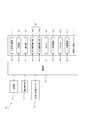
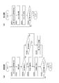
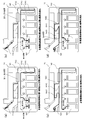
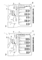
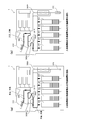
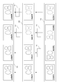
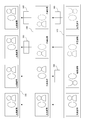
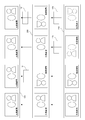
- FIG. 1 is a schematic diagram showing the configuration of the money depositing and dispensing machine according to the first embodiment.
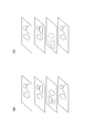
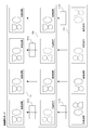
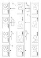
- Fig.2 (a) is a figure which shows the state of the banknote which flows through a conveyance part based on 1st Embodiment
- FIG.2 (b) is the reverse of the banknote by the 1st inversion part based on 1st Embodiment.
- FIG. 2C is a diagram for explaining the reverse of the banknote by the second reversing unit according to the first embodiment.
- FIG. 3 is a block diagram showing a main configuration of the money depositing and dispensing machine according to the first embodiment.
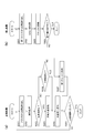
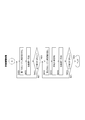
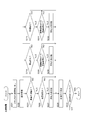
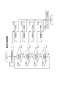
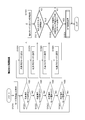
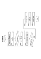
- FIG. 4 is a flowchart showing the control operation of the deposit process according to the first embodiment.
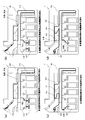
- FIG.5 (a) is a figure which shows the flow of the surface banknote and the top and bottom banknote in the money depositing / withdrawing machine in the money_receiving
- FIG.5 (b) concerns on 1st Embodiment. It is a figure which shows the flow of an astronomical banknote and a background banknote in the money depositing / withdrawing machine in a money_receiving
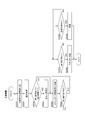
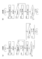
- FIG. 6A is a flowchart illustrating the control operation of the withdrawal process according to the first embodiment
- FIG. 6B is a flowchart illustrating the control operation of the return process according to the first embodiment. .
- FIG.7 (a) is a figure which shows the flow of the background banknote in the money depositing / withdrawing machine in payment processing based on 1st Embodiment
- FIG.7 (b) is drawing
- FIG.7 (c) is the surface banknote and the top and bottom banknote in the money depositing / withdrawing machine in 1st Embodiment based on 1st Embodiment.
- FIG.7 (d) is a figure which shows the flow of the surface banknote and the top and bottom banknote in the money depositing / withdrawing machine in the return process based on 1st Embodiment.
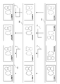
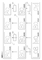
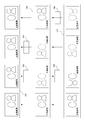
- FIG. 8 is a diagram illustrating a transition of the state of the banknote when the depositing process and the dispensing process according to the first embodiment are performed.
- FIG. 9 is a flowchart showing the control operation of the counting arrangement process according to the first embodiment.
- FIG. 10 is a flowchart showing the control operation of the counting arrangement process according to the first embodiment.
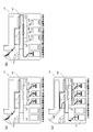
- FIG.11 (a) is a figure which shows a flow until it accommodates in the 1st cassette and 2nd cassette of the surface banknote and the top and bottom banknote in the money depositing / withdrawing machine in the count arrangement process based on 1st Embodiment
- FIG.11 (b) is a figure which shows a flow until it accommodates in the 1st cassette and 2nd cassette of an astronomical banknote and an underground banknote in the money depositing / withdrawing machine in the count arrangement
- FIG.11 (c) is a figure which shows a flow until it is thrown into the payment
- FIG.11 (d) It is a figure which shows a flow until it is thrown out to the withdrawal part of the underground banknote in the money depositing / withdrawing machine in the counting arrangement processing according to the first embodiment.
- FIG. 12 is a flowchart illustrating the control operation of the degeneration mode setting process according to the first modification.
- FIG. 13 is a schematic diagram illustrating the configuration of the money depositing and dispensing machine according to the second modification.
- FIG. 14A is a flowchart illustrating the control operation of the banknote alignment mode setting process according to the modification example 2
- FIG. 14B is a diagram illustrating an example of the mode setting screen according to the modification example 2.
- FIG. 15 is a flowchart illustrating the control operation of the deposit process according to the second modification.
- FIG. 16A is a diagram illustrating a flow of banknotes that does not pass through the second reversing unit in the money depositing / dispensing machine in the depositing process according to the second modification
- FIG. 16B is a money depositing / dispensing in the depositing process.
- FIG. 17 is a flowchart illustrating a control operation of the withdrawal process according to the second modification.
- FIG. 18A is a diagram illustrating the flow of banknotes passing through the first reversing unit in the money depositing and dispensing machine according to the modification example 2, and FIG. It is a figure which shows the flow of the banknote which does not pass through the 1st inversion part in the money depositing / withdrawing machine in the payment processing.
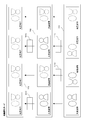
- FIGS. 19A to 19E are views showing states of banknotes to be dispensed to the dispensing unit in the front / back and top / bottom alignment mode, the front / back alignment mode, the top / bottom alignment mode, the left / right alignment mode and the non-alignment mode, respectively.
- FIG. 20 is a flowchart illustrating the control operation of the automatic review process according to the second modification.
- FIG. 21A is a diagram showing the flow of banknotes from the stacker in the money depositing / dispensing machine in the automatic scrutiny processing according to the second modification
- FIG. 21B is the inside of the money depositing / dispensing machine in the automatic scrutiny processing.
- FIG.21 (c) is a figure which shows the flow of the banknote through the 2nd inversion part in the money depositing / withdrawing machine in an automatic close-up process.
- FIG.21 (d) is a figure which shows the flow of the banknote from the 2nd cassette in the money depositing / withdrawing machine in the automatic scrutiny processing based on the example 2 of a change.
- FIG. 22 is a schematic diagram showing the configuration of the money depositing and dispensing machine according to the third modification.
- FIG. 23A is a diagram illustrating the flow of the surface banknotes and the top and bottom banknotes in the money depositing / dispensing machine in the depositing process according to the third modification
- FIG. 23B is the depositing according to the third modification. It is a figure which shows the flow of an astronomical banknote and a background banknote in the money depositing / withdrawing machine in a process.
- FIG. 24A is a diagram illustrating the flow of the background banknotes in the money depositing and dispensing machine according to the modification example 3
- FIG. 24B is a withdrawal process according to the modification example 3.
- FIG. 24 (c) shows the flow of the surface banknotes and the top and bottom banknotes in the money depositing / dispensing machine according to the third modification.
- FIG.24 (d) is a figure which shows the flow of the surface banknote and the top and bottom banknote in the money depositing / withdrawing machine in the return process based on the example 3 of a change.
- FIG. 25 is a flowchart illustrating the control operation of the automatic inspection process according to the fourth modification.
- Fig.26 (a) is a figure which shows the flow in the money depositing / withdrawing machine of the astronomical banknote and ground banknote which are moved to the 1st cassette in the automatic scrutiny processing based on the modification 4, and FIG.26 (b) is shown.
- FIG.26 (c) is a figure which shows the flow in the money depositing / withdrawing machine of the astronomical banknote and ground banknote which are returned to the stacker in the automatic inspection process based on the example 4 of a change
- FIG.26 (d) is a change. It is a figure which shows the flow in the money depositing / withdrawing machine of the surface banknote and the top and bottom banknote which are returned to the stacker in the automatic scrutiny processing concerning Example 4.
- FIG.26 (d) is a change. It is a figure which shows the flow in the money depositing / withdrawing machine of the surface banknote and the top and bottom banknote which are returned to the stacker in the automatic scrutiny processing concerning Example 4.
- FIG. 27 is a flowchart illustrating a control operation of the withdrawal process according to the fifth modification.
- FIGS. 28A and 28B show an example of the state of banknotes to be dispensed to the dispensing unit when the discharge of the surface banknotes or the heavenly banknotes from the stacker continues for a set number or more according to the fifth modification.
- FIG. FIG. 29 is a schematic diagram illustrating a configuration of a money depositing and dispensing machine according to Modification 6.
- FIG. 30 is a block diagram illustrating a main configuration of a money depositing and dispensing machine according to the sixth modification.
- FIG. 31 (a) to 31 (d) show the direction patterns of banknotes to be dispensed to the dispensing unit in the top alignment mode, the top surface alignment mode, the top / bottom alignment mode, and the background alignment mode, respectively, according to the modification example 6.
- FIG. 32A is a diagram illustrating an example of a menu screen including a mode setting button according to the modification example 6
- FIG. 32B is a menu screen according to the modification example 6 including no mode setting button.
- FIG. 32C is a diagram illustrating an example of a mode setting screen according to the sixth modification.
- FIG. 33 is a flowchart illustrating the control operation of the alignment mode setting process according to the sixth modification.
- FIG. 34 is a diagram illustrating a configuration of a correspondence table according to the sixth modification.
- FIG. 35 is a flowchart illustrating the control operation of the deposit process according to the sixth modification.
- FIG. 36A is a diagram illustrating the flow of the first banknote and the second banknote in the money depositing / dispensing machine in the depositing process according to the modification example 6, and FIG. It is a figure which shows the flow of the 3rd banknote and the 4th banknote in the money depositing / withdrawing machine in a money_receiving
- FIG. 37A is a flowchart illustrating the control operation of the withdrawal process according to the modification example 6, and FIG. 37B is a flowchart illustrating the control operation of the return process according to the modification example 6.
- FIG. 37A is a flowchart illustrating the control operation of the withdrawal process according to the modification example 6
- FIG. 37B is a flowchart illustrating the control operation of the return process according to the modification example 6.
- FIG. 38A is a diagram illustrating a flow of the third banknote in the money depositing and dispensing machine according to the modification example 6, and FIG. 38B is a withdrawal process according to the modification example 6. It is a figure which shows the flow of the 4th banknote in the money depositing / withdrawing machine in FIG. 38, FIG.38 (c) is the flow of the 1st banknote and the 2nd banknote in the money depositing / withdrawing machine in the payment processing based on the example 6 of a change.
- FIG.38 (d) is a figure which shows the flow of the 1st banknote and the 2nd banknote in the money depositing / withdrawing machine in the return process based on the example 6 of a change.
- FIG. 38A is a diagram illustrating a flow of the third banknote in the money depositing and dispensing machine according to the modification example 6, and FIG. 38B is a withdrawal process according to the modification example 6. It is a figure which shows the flow of the 4th banknote in the money depositing
- FIG. 39 is a diagram illustrating the transition of the state of banknotes when deposit processing and withdrawal processing are performed when the celestial alignment mode is set according to the sixth modification.
- FIG. 40 is a diagram illustrating transition of the state of banknotes when the depositing process and the dispensing process are performed when the ground alignment mode is set according to the sixth modification.
- FIG. 41 is a diagram illustrating transition of the state of banknotes when deposit processing and withdrawal processing are performed when the top / bottom alignment mode is set according to the modification example 6.
- FIG. 42 is a diagram illustrating a transition of the state of banknotes when the depositing process and the dispensing process are performed when the background alignment mode is set according to the sixth modification.
- FIG. 43 is a flowchart illustrating the control operation of the count reduction process according to the sixth modification.
- FIG. 44 is a flowchart illustrating the control operation of the count reduction process according to the sixth modification.
- FIG. 45 (a) is a diagram illustrating a flow until the first banknote and the second banknote are stored in the first cassette and the second cassette in the money depositing and dispensing machine in the counting and arranging process according to the modification example 6
- FIG. 45 (b) is a diagram showing a flow until the third banknote and the fourth banknote are stored in the first cassette and the second cassette in the money depositing / dispensing machine in the counting and organizing process according to the sixth modification.
- FIG.45 (c) is a figure which shows a flow until it is thrown into the payment part of the 4th banknote in the money depositing / withdrawing machine in the count arrangement
- FIG.45 (d) is a change. It is a figure which shows a flow until it is thrown into the payment part of the 3rd banknote in the money depositing / withdrawing machine in the count arrangement
- FIG. FIG. 46 is a flowchart illustrating the control operation of the alignment mode setting process according to the seventh modification.
- FIG. 47 is a flowchart illustrating the control operation of the direction change process included in the alignment mode setting process according to the modification example 7.
- FIG. 48A is a diagram showing the flow of banknotes from the stacker to the first cassette in the money depositing and dispensing machine in the direction changing process according to the modification example 7, and FIG. It is a figure which shows the flow of the banknote from the 1st cassette to a stacker in the money depositing / withdrawing machine in the direction change process which concerns.
- FIG. 49 is a perspective view showing an appearance of a banknote handling machine according to the second embodiment.
- FIG. 50 is a schematic diagram illustrating a configuration of a loose banknote processing unit according to the second embodiment.
- FIG. 51 is a schematic diagram illustrating a configuration of a bundled banknote handling unit according to the second embodiment.
- FIG. 52 is a block diagram showing a main configuration of a banknote handling machine according to the second embodiment.
- FIG. 53 (a) is a flowchart showing the control operation of the deposit process according to the second embodiment
- FIG. 53 (b) is a flowchart showing the control operation of the withdrawal process according to the second embodiment.
- FIG. 54 (a) is a diagram showing the flow of the surface banknote and the background banknote in the banknote handling machine in the deposit process according to the second embodiment
- FIG. 54 (b) is according to the second embodiment. It is a figure which shows the flow of an astronomical banknote and a sky banknote in the banknote processing machine in a money_receiving
- FIG.55 (a) is a figure which shows the flow of the top and bottom banknote in the banknote processing machine in the payment processing based on 2nd Embodiment
- FIG.55 (b) is the payment based on 2nd Embodiment. It is a figure which shows the flow of an astronomical banknote in the banknote processing machine in a process.
- FIG. 56 is a diagram illustrating transition of the state of banknotes when the depositing process and the dispensing process are performed according to the second embodiment.
- FIG. 57 is a flowchart showing the control operation of the bundling arrangement process according to the second embodiment.
- FIG. 58 (a) is a diagram illustrating a flow up to the temporary storage unit for banknote banking in the banknote handling machine in the bundling processing according to the second embodiment
- FIG. 58 (b) is a diagram illustrating the second embodiment. It is a figure which shows a flow to the arrangement
- FIG. 59 is a schematic diagram illustrating a configuration of a loose banknote processing unit according to a modified example.
- FIG.60 (a) is a figure which shows the flow of the surface banknote and the ground banknote in the banknote processing machine in the money_receiving
- FIG.60 (b) is the banknote in the money_receiving
- FIG. 61 is a flowchart showing the control operation of the withdrawal process according to the modified example.
- 62A is a diagram illustrating the flow of the top and bottom banknotes in the banknote handling machine in the withdrawal process according to the modification example, and FIG. 62B is the banknote processing in the withdrawal process according to the modification example.
- FIG. 63 is a diagram illustrating the flow of the surface banknote and the background banknote in the banknote handling machine in the withdrawal process according to the modified example.
- FIG. 64 is a diagram illustrating transition of the state of banknotes when the depositing process and the dispensing process are performed according to the modification example.
- FIG. 65 is a flowchart showing the control operation of the automatic review process according to the modified example.
- FIG. 66 (a) is a diagram illustrating the flow of the top banknote and the top banknote in the banknote handling machine in the automatic scrutiny process according to the modified example
- FIG. 66 (b) is the automatic scrutiny according to the modified example.
- FIG. 67 is a diagram for explaining a money depositing and dispensing machine according to another modification.
- FIG. 68 is a diagram for explaining a banknote handling machine according to another modification.
- FIG. 69 is a diagram for explaining a money depositing and dispensing machine according to another modification.
- FIG. 70 is a diagram for explaining a banknote handling machine according to another modification.
- the first inversion units 161 and 380 correspond to the “upside-down inversion unit” described in the claims.
- the second reversing units 170 and 390 correspond to the “left / right reversing unit” recited in the claims.
- the bundling mechanism 510 corresponds to the “binding portion” described in the claims.
- an astronomical banknote and a background banknote correspond to the "1st banknote” of Claim 2 of a claim
- a surface banknote and a top banknote are Claim 2 of a claim
- the astronomical banknote corresponds to the “third banknote” in claim 2
- the background banknote corresponds to the “second banknote” in claim 2.
- an astronomical banknote and a top banknote correspond to the "1st banknote” of Claim 4 of a claim
- a surface banknote and a ground banknote are Claim 4 of a claim
- the astronomical banknote corresponds to the “third banknote” in claim 4
- the top banknote corresponds to the “fourth claim” in the claim 4.
- a money depositing and dispensing machine 1 which is an embodiment of the banknote handling apparatus of the present invention will be described with reference to FIGS. 1 to 3.
- the money depositing / dispensing machine 1 is installed inside a counter of a bank or the like and is used by a teller who performs a money depositing / withdrawing operation.
- the money depositing / dispensing machine 1 includes a bill depositing / dispensing unit 11 and a coin depositing / dispensing unit 12 in a housing 10 constituting an outer shell.
- the banknote deposit / withdrawal unit 11 is provided on the lower side of the housing 10 and performs banknote deposit / withdrawal processing.
- the coin deposit / withdrawal unit 12 is provided on the upper side in the housing 10 and performs coin deposit / withdrawal processing and the like.
- the banknote deposit / withdrawal unit 11 includes a depositing unit 110, a dispensing unit 120, a reject unit 130, a transport unit 140, an identification unit 150, and a front / back aligning unit 160 (a first reversing unit 161 and a non-reversing unit 162).
- the second reversing unit 170, the two cassettes 180, the two temporary storage units 190 for the cassette 180, the three stackers 200, and the three temporary storage units 210 for the stacker 200 are provided.
- the front / back aligning section 160 corresponds to the “second banknote aligning section” described in the claims
- the second reversing section 170 corresponds to the “first banknote aligning section” described in the claims.
- the depositing unit 110, the dispensing unit 120, and the rejecting unit 130 are provided in the vicinity of the upper front in the housing 10.
- a deposit port (not shown) and a withdrawal port (not shown) that are opened and closed by a shutter are provided.
- the depositing unit 110 is connected to the depositing port, and the banknotes are inserted into the depositing unit 110 through the depositing port.
- the withdrawal unit 120 and the rejection unit 130 are connected to the withdrawal port, and the banknotes are taken out from the withdrawal unit 120 and the rejection unit 130 through the withdrawal port.
- the depositing unit 110 includes a deposit feeding mechanism 111.
- the deposit payout mechanism 111 feeds the banknotes inserted into the deposit unit 110 to the transport unit 140 one by one.
- the dispensing unit 120 mainly receives banknotes fed from the stacker 200.
- the reject unit 130 mainly receives banknotes whose attributes (authentication, denomination, top and bottom, etc.) cannot be identified by the identification unit 150 and are not regarded as normal banknotes.
- the conveyance unit 140 includes a belt mechanism, a roller mechanism, and the like, and includes a main conveyance path 141, a first deposit conveyance path 142, a withdrawal conveyance path 143, a reject conveyance path 144, two cassette conveyance paths 145, Three stacker conveyance paths 146 and a second deposit conveyance path 147 are included.
- the main transport path 141 is formed in a reverse L-shaped loop shape so as to extend in the front-rear direction in the housing 10, and in FIG. 1, bills are fed in the clockwise direction (solid arrow) and the counterclockwise direction (broken line arrow). It can be transported.
- the first deposit conveyance path 142 is provided between the deposit section 110 and the main conveyance path 141.
- the withdrawal conveyance path 143 is provided between the withdrawal unit 120 and the main conveyance path 141.
- the reject conveyance path 144 is provided between the reject unit 130 and the main conveyance path 141.
- the cassette conveyance path 145 is provided between the cassette 180 and the temporary storage unit 190 and the main conveyance path 141.
- the stacker transport path 146 is provided between the stacker 200 and the temporary storage unit 210 and the main transport path 141.
- the second deposit conveyance path 147 branches from the main conveyance path 141, passes through the second reversing unit 170, and then joins the main conveyance path 141 again.
- a rectangular banknote is transported to the transport unit 140 such that its short direction (vertical direction) faces the transport direction, and its long direction (left and right direction) faces the transport direction. May be transported to the section 140.
- a banknote is the conveyance part 140 in four states shown to Fig.2 (a). Can flow.
- the conveyance unit 140 is provided in the horizontal direction, provided in the vertical direction, or folded in a U shape. However, in order to define the direction of the banknote, the conveyance unit 140 is developed so as to go straight in the horizontal direction. Assume a state.
- top banknote in which the head of the portrait drawn on the banknote faces the transport direction
- bottom banknote A banknote facing in the direction facing the transport direction
- surface banknote a banknote facing in the direction opposite to the top direction facing the transport direction
- ground banknote A banknote facing in the opposite direction is defined as a “ground banknote”.
- the identification unit 150 is provided at the rear of the upper loop of the main conveyance path 141.
- the identification part 150 identifies the attribute of the banknote which flows through the conveyance part 140, and outputs an identification result to the control part mentioned later.
- the identified attributes include the authenticity and denomination of the banknote, the front and back of the banknote, and the orientation of the banknote.
- the identification unit 150 has a function of counting the number of banknotes.
- the front / back aligning unit 160 is arranged in front of the identification unit 150, that is, upstream of the flow of banknotes when depositing from the identification unit 150, and aligns the front and back of the banknotes flowing through the transport unit 140.
- the front / back aligning unit 160 includes a first reversing unit 161 and a non-reversing unit 162 that constitute a part of the main transport path 141.
- the first reversing unit 161 includes a reversing mechanism for reversing the bills by the switchback method. As shown in FIG.
- the banknote that has passed through the first reversing unit 161 is reversed front and back along the short side direction of the banknote, that is, the top-to-bottom direction, and the front and back are switched.
- the banknote that has passed through the first reversing unit 161
- the non-reversing portion 162 and a back-facing banknote flows through the first reversing section 161
- all banknotes after passing through the front-back aligning section 160 are aligned front-facing.
- the second reversing unit 170 is provided in the rear part of the housing 10 and below the main conveyance path 141 so that the longitudinal direction thereof is the vertical direction.
- the 2nd inversion part 170 is located in the downstream of the flow of the banknote at the time of money_receiving
- FIG. By arranging the second reversing unit 170 in such an arrangement, compared to the case where the first reversing unit 161 and the second reversing unit 170 whose longitudinal direction is the front-rear direction are arranged side by side in front of the identification unit 150, The size of the money depositing and dispensing machine 1 can be made compact in the front-rear direction.
- the second reversing unit 170 includes a reversing conveyance path 171 formed in a spiral shape extending in the vertical direction. As shown in FIG. 2C, the banknote that has passed through the reverse conveyance path 171 is reversed front and back along the longitudinal direction of the banknote, that is, the left-right direction, and the front and back and the left and right are switched.
- the two cassettes 180 and the three stackers 200 are provided in the casing 10 so as to be lined up in the front and rear direction below the transport unit 140. Two cassettes 180 are provided in front of the three stackers 200.
- the second reversing unit 170 is located behind the last stacker 200.
- the cassette 180 is detachable from the housing 10 and can be taken in and out of the housing 10 by opening a door (not shown) provided at the lower front of the housing 10.
- the cassette 180 is mainly used for storing banknotes collected from the stacker 200 and banknotes to be replenished to the stacker 200.
- the cassette 180 is used for temporarily storing banknotes in the banknote counting and organizing process described later and the automatic scrutiny process for automatically scrutinizing banknotes in the stacker 200.
- banknotes are stored so as to be stacked one above the other.
- An elevating stage 180a is provided in the cassette 180 to raise and lower the stored banknotes.
- the front cassette 180 becomes the first cassette 181 and the rear cassette 180 becomes the second cassette 182.
- One cassette 180 can also be used for storing 2,000 yen tickets, old tickets, lost tickets, and the like.
- the temporary storage unit 190 for the cassette 180 is disposed above the corresponding cassette 180. Temporary holding unit 190 temporarily holds banknotes stored in cassette 180.
- a feeding mechanism (not shown) is provided on the entrance / exit side of the temporary storage unit 190, and the banknotes in the cassette 180 can be delivered to the cassette conveyance path 145 through the temporary storage unit 190.
- the stacker 200 is used to store deposited banknotes in denominations. For example, denominations of 10,000 yen, 1,000 yen, and 5,000 yen can be assigned to each of the three stackers 200.
- banknotes are stored so as to be stacked up and down.
- An elevating stage 200 a is provided in the stacker 200 for elevating the stored banknotes.
- the temporary storage unit 210 for the stacker 200 is disposed above the corresponding stacker 200.
- the temporary storage unit 210 temporarily stores banknotes stored in the stacker 200.
- a feeding mechanism (not shown) is provided on the entrance / exit side of the temporary storage unit 210, and the banknotes in the stacker 200 can be delivered to the stacker transport path 146 through the temporary storage unit 210.
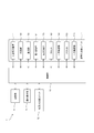
- FIG. 3 is a block diagram showing the main configuration of the money depositing and dispensing machine 1 according to the present embodiment.
- the money depositing and dispensing machine 1 includes a control unit 13, a storage unit 14, and an operation display unit 15 in addition to the above-described banknote depositing / dispensing unit 11 and coin depositing / dispensing unit 12.
- the control unit 13 includes an arithmetic circuit such as a CPU (Central Processing ⁇ Unit), and in accordance with an operation program stored in the storage unit 14, each component of the banknote deposit / withdrawal unit 11 (a deposit feeding mechanism 111, a transport unit 140, an identification unit) 150, the first reversing unit 161, the second reversing unit 170, the cassette 180, the temporary holding unit 190, the stacker 200, the temporary holding unit 210, and the like, and the components of the coin deposit / withdrawal unit 12 are controlled.
- the storage unit 14 includes storage media such as a ROM (Read Only Memory), a RAM (Random Access Memory), and a hard disk, stores an operation program of the control unit 13, and a work area during the control process of the control unit 13. Used as
- the operation display unit 15 is composed of a touch panel including a display and a touch sensor.
- the operation display unit 15 displays various images (screens) on the display, and detects a user's touch operation on the display by a touch sensor.
- the operation display unit 15 is provided, for example, at the front end of the upper surface of the housing 10.
- the money depositing / dispensing machine 1 has the front and back sides and the top and bottom of a plurality of dispensed banknotes as a result of performing the depositing process and the dispensing process.
- the dispensed banknotes are aligned with the astronomical banknotes.
- the control unit 13 feeds out banknotes (separated banknotes) one by one from the depositing unit 110 and transports them to the transport unit 140 (S101), and the attributes of the banknotes flowing through the transport unit 140 (denomination, denomination,
- the identification unit 150 identifies the front and back surfaces, the top and the bottom, and the like (S102).
- the control part 13 determines whether a banknote is a surface banknote or a top and bottom banknote based on the identification result in the identification part 150 (S103).
- the control unit 13 passes the banknote through the second reversing unit 170 and swaps the front and back sides and the left and right sides of the banknote (S104). In the temporary storage unit 210 (S105).
- the control unit 13 does not pass the banknote through the second reversing unit 170 and temporarily stores the banknote 200. It is stored in the holding unit 210 (S105).
- the control unit 13 repeats the processing from S101 to S105 until all the banknotes are paid out from the depositing unit 110.
- the control unit 13 waits for an approval operation (S107).
- the control unit 13 discharges the banknote from the temporary storage unit 210 and stores it in the stacker 200 (S108). Thus, the deposit process is completed.
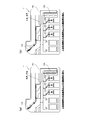
- the surface banknote and the top banknote among the banknotes deposited in the depositing unit 110 are stacked via the second reversing unit 170 as shown in FIG.
- the astronomical banknote and the background banknote are stored in the stacker 200 without passing through the second reversing unit 170.
- the surface banknote is converted into a background banknote by the second reversing unit 170 and stored in the stacker 200
- the top banknote is converted into the top banknote by the second reversing unit 170. It is stored in.
- the astronomical banknote and the background banknote are stored in the stacker 200 as they are. Thus, after depositing, only the celestial banknote and the background banknote are stored in the stacker 200.
- the control unit 13 feeds out banknotes one by one from the stacker 200 and transports them to the transport unit 140 (S201), and attributes of the banknotes flowing through the transport unit 140 (denomination, front / back, top / bottom direction). Etc.) is identified by the identification unit 150 (S202).
- the control part 13 determines whether a banknote is a background banknote based on the identification result in the identification part 150, and whether a banknote is an astronomical banknote (S203, S204). .
- the control unit 13 passes the banknote through the first reversing unit 161 and switches the front and back of the banknote and the top and bottom (S205). It throws out (S206).
- the banknote to be dispensed is an astronomical banknote unless it is a background banknote.
- an error such as a jam occurs in the transport unit 140 at the time of withdrawal, and the banknotes remaining in the transport unit 140 are returned to the stacker 200 by a teller's hand, so that the banknotes in the stacker 200 can be touched from the outside.
- the surface banknotes or the top and bottom banknotes are mixed in the stacker 200. In such a case, the surface banknote or the top banknote can flow through the transport unit 140 during the withdrawal process.
- the control unit 13 does not pass the banknote through the first reversing unit 161, but throws it through the non-reversing unit 162 to the dispensing unit 120 (S206).
- the surface banknote or the top banknote flows through the transport unit 140 due to the above-described factors, it can be determined in S204 that the banknote is not the top banknote.
- the control unit 13 does not throw the banknote, that is, the surface banknote or the top and bottom banknotes, into the dispensing unit 120, and passes the non-inverted unit 162. It is stored in one cassette 181 (S207).
- the control unit 13 repeats the processing from S201 to S207 until the number of banknotes designated by the withdrawal operation, that is, the banknote of the number of withdrawals is thrown into the withdrawal unit 120.
- the control unit 13 ends the withdrawal process.
- the background banknote out of the banknotes withdrawn from the stacker 200 is withdrawn 120 via the first reversing unit 161 as shown in FIG.
- the astronomical banknote is thrown into the dispensing unit 120 via the non-inversion unit 162.
- the background banknote is converted into an astronomical banknote by the first reversing unit 161 and thrown into the dispensing unit 120, and the astronomical banknote is thrown into the dispensing unit 120 in that state. It is.
- the banknotes are thrown into the dispensing unit 120 with the front and back sides and the top and bottom aligned.
- the control part 13 pays out one banknote from the 1st cassette 181 one by one (S301), and passes the drawn banknote through the 2nd inversion part 170, and the front and back of the banknote, After the left and right are switched (S302), they are stored in the stacker 200 (S303).
- the control unit 13 repeats the processing from S301 to S303 until all the banknotes are drawn out from the first cassette 181.
- S304: YES the control unit 13 ends the returning process.
- the surface banknotes and the top and bottom banknotes fed out from the first cassette 181 are stored in the stacker 200 via the second reversing unit 170 as shown in FIG.
- the surface banknote is converted into a background banknote and stored in the stacker 200
- the top banknote is converted into a top banknote and stored in the stacker 200.
- the first cassette 181 is used to store the surface banknote and the top banknote.
- the second cassette 182 may be used for storing these banknotes, or both cassettes 181 and 182 may be used.
- the temporary storage part 190 corresponding to at least any one of the 1st cassette 181 and the 2nd cassette 182 may be used for storage of a surface banknote and a top and bottom banknote.
- ⁇ Countermeasure processing> the counting arrangement process performed by the money depositing and dispensing machine 1 will be described with reference to FIGS. 9 to 11.
- a predetermined number of banknotes (separate banknotes) of a predetermined denomination inserted into the depositing unit 110 are aligned on the front and back and the top and bottom, and a predetermined number of sheets (for example, 100 sheets, hereinafter referred to as “numbered sheets”).
- numbered sheets for example, 100 sheets, hereinafter referred to as “numbered sheets”.
- the process until the bills inserted into the depositing unit 110 are stored in the first cassette 181 and the second cassette 182 corresponds to the “deposit process” described in the claims, and the first cassette The process until the banknotes in 181 and the second cassette 182 are thrown into the withdrawal unit 120 corresponds to the “withdrawal process” described in the claims.
- the control unit 13 feeds out banknotes one by one from the depositing unit 110 and transports them to the transport unit 140 (S 401), and attributes of the banknotes flowing through the transport unit 140 (denomination, front and back) , The orientation of the top and the bottom) is identified by the identification unit 150 (S402).
- the control unit 13 determines which of the four patterns (see FIG. 2A) the banknote is based on the identification result in the identification unit 150 (S403). .
- the control unit 13 stores the banknote in the first cassette 181 without passing through the second reversing unit 170 (S404).
- a banknote is a top and bottom banknote (S403: top and bottom)
- the control part 13 passes the banknote through the 2nd inversion part 170, and after replacing the front and back, and right and left of the banknote (S405), the 1st cassette 181 (S404).
- the banknote is a background banknote (S403: background)
- the control unit 13 stores the banknote in the second cassette 182 without passing through the second reversing unit 170 (S406).
- the control unit 13 passes the banknote through the second reversing unit 170 and swaps the front and back and the left and right sides of the banknote (S407), and then stores the banknote in the second cassette 182. (S406).
- the control unit 13 repeats the processing from S401 to S407 until the banknotes are fed out from the depositing unit 110 by the number of arranged sheets.
- the surface banknotes and the top banknotes are converted into the top banknotes and the top banknotes via the second reversing unit 170 as shown in FIG.
- the first cassette 181 and the second cassette 182 are accommodated.
- astronomical banknotes and background banknotes are stored in the first cassette 181 and the second cassette 182 without passing through the second reversing unit 170 as shown in FIG.
- only the astronomical banknote is stored in the first cassette 181, and only the background banknote is stored in the second cassette 182.
- the control unit 13 feeds the banknotes one by one from the first cassette 181 (S409), and passes the fed banknotes through the non-inversion unit 162.
- the money is dispensed to the withdrawal unit 120 (S410).
- the control unit 13 pays out banknotes one by one from the second cassette 182 (S412), and the fed banknotes are sent to the first reversing unit 161.
- the banknote is thrown into the dispensing unit 120 (S414).
- the control unit 13 ends the counting arrangement process.
- the top banknote of the first cassette 181 is thrown out to the withdrawal unit 120 via the non-inversion unit 162, and the underground banknote of the second cassette 182 is ), It is converted into an astronomical banknote via the first reversing unit 161 and thrown into the dispensing unit 120.
- the astronomical banknote is thrown into the dispensing unit 120. That is, the arranged number of banknotes is thrown into the dispensing unit 120 with the front and back sides and the top and bottom aligned.
- the first cassette 181 and the second cassette 182 are used to store astronomical banknotes and background banknotes.
- the two temporary storage units 190 for the cassette 180 may be used to store the astronomical banknotes and the background banknotes, or two of the three temporary storage units 210 for the stacker 200 may be used. Good.
- banknotes with the front and back sides and the top and bottom aligned can be thrown into the dispensing unit 120, these banknotes look good and are easy to handle.
- the banknote In the depositing process, the banknote is routed or bypassed through the second reversing unit 170, and in the withdrawal process, the banknote is routed or bypassed through the first reversing unit 161, so that it is necessary to align the front and back and the top and bottom.
- Time can be distributed to the deposit process and the withdrawal process, and an increase in the time required for depositing banknotes into the stacker 200 (temporary holding unit 210) can be suppressed.
- the stacker 200 Due to the occurrence of an error or the like, the stacker 200 contains banknotes (surface banknotes and banknotes) that are different from the banknotes in the correct orientation (top banknotes and background banknotes) to be normally stored. However, since the banknotes in the wrong direction are not thrown into the dispensing unit 120, only the banknotes with the front and back surfaces and the top and bottom aligned can be thrown into the dispensing unit 120.
- banknotes in the wrong direction can be converted into banknotes (top and bottom banknotes) in the correct direction and returned to the stacker 200. It is possible to return to the storage state.
- the top banknote and the top banknote are stored in different cassettes 180, so that when the banknote is thrown into the dispensing unit 120, the identification unit 150 does not need to identify the front and back. Therefore, even if banknotes are generated that cannot be distinguished from each other for some reason, such as being conveyed with an abnormal inclination, these banknotes can be appropriately routed or detoured through the first reversing unit 161. Accordingly, since the front and back sides cannot be identified, a part of the banknotes is not lost, and the banknotes with the front and back sides and the top and bottom aligned can be securely thrown into the dispensing unit 120 by the number of arranged sheets.
- the money depositing / dispensing machine 1 is configured such that the depositing process and the dispensing process can be continued when an error occurs in the first reversing unit 161 and the second reversing unit 170.
- the reduction mode setting process is executed in parallel with the depositing process and the dispensing process.
- the reduction mode setting process is executed, if an error occurs in the second reversing unit 170 during the execution of the depositing process, the left / right reversing degenerate mode is set to continue the depositing process without using the second reversing unit 170.
- the upside-down reversing mode in which the withdrawal process is continued without using the first reversing unit 161. .
- control unit 13 determines whether an error has occurred in first inversion unit 161 based on input signals from various sensors (not shown) provided in first inversion unit 161. (S501). Further, the control unit 13 determines whether an error has occurred in the second inversion unit 170 based on input signals from various sensors (not shown) provided in the second inversion unit 170 (S502).
- the error in the first inversion unit 161 includes a jam in addition to the failure, but the error in the second inversion unit 170 does not include the jam. Even if the banknotes jammed in the first reversing unit 161 are released during the withdrawal process, it is not necessary to cause a new banknote to be withdrawn from the stacker 200, but the second banknote during the deposit process. This is because if the banknotes jammed in the reversing unit 170 are left undisturbed, the deposit amount (the number of deposits) cannot be determined, resulting in trouble.
- the control unit 13 determines whether or not a switching operation for switching to the top and bottom reversing degeneration mode has been performed (S503).
- the switching operation can be a pressing operation of a switching button arranged on a predetermined screen.
- the control unit 13 sets the upside-down inversion / degeneration mode (S504).
- the control unit 13 performs a switching operation for switching to the left / right reversing degenerate mode (S505: YES), Setting is performed (S506).
- the control unit 13 temporarily interrupts the depositing process when an error occurs in the second reversing unit 170 during the depositing process shown in FIG. After that, when the left / right reverse reduction mode is set, the control unit 13 resumes the deposit process. However, after restarting, the control unit 13 does not execute the processes of S103 and S104 in the depositing process shown in FIG. 4 and does not pass through the second reversing unit 170 for all banknotes fed out from the depositing unit 110. In the temporary storage unit 210. Similarly, if an error occurs in the first reversing unit 161 during the execution of the withdrawal process shown in FIG. 5A, the control unit 13 temporarily interrupts the withdrawal process.
- the control unit 13 resumes the withdrawal process. However, after the restart, the control unit 13 does not execute the processes of S203, S204, S205, and S207 in the withdrawal process shown in FIG. 5A, and the first reversing unit 161 for all banknotes fed out from the stacker 200. The money is dispensed to the withdrawal unit 120 via the non-reversing unit 162 without passing through.
- switching to the upside-down inversion degeneration mode and the left-right inversion degeneration mode is performed by the switching operation.
- switching to the upside-down inversion degeneration mode and the left-right inversion degeneration mode may be performed without a switching operation.
- the top-and-bottom inversion degeneration mode is canceled automatically when the error in the first reversing unit 161 is cancelled or upon receiving a predetermined canceling operation.
- the configuration may be such that the left-right reversing degeneration mode is canceled automatically when the error in the second reversing unit 170 is cancelled, or in response to a predetermined canceling operation.
- the second reversing unit 170 is provided in the lower loop of the main conveyance path 141 such that the longitudinal direction thereof is the front-rear direction.
- a third deposit conveyance path that branches from the main conveyance path 141 below the second reversing unit 170 and extends forward along the second reversing unit 170 and then merges with the main conveyance path 141 again.
- 148 is provided, and three stacker transport paths 146 are connected to the third deposit transport path 148. Further, the height of the three stackers 200 in the vertical direction is reduced. In this configuration, the size of the device body in the front-rear direction can be reduced as compared with the money depositing and dispensing machine 1 of the first embodiment.
- the cassette 180 is used in the deposit process.
- the banknotes that have passed through the second reversing unit 170 are temporarily stored in the cassette 180 and transferred from the cassette 180 to the stacker 200.
- the front and back and top and bottom of the banknotes to be dispensed are aligned, only the front and back are aligned, only the top and bottom are aligned, It is possible to select whether only the left and right are aligned or not.
- the banknote alignment mode setting process is started by an operation for setting the banknote alignment mode by a teller or the like.
- the control unit 13 displays a mode setting screen on the operation display unit 15 (S601).
- the mode setting screen includes a front / rear top / bottom button B1, a front / back button B2, a top / bottom button B3, a left / right button B4, and a misalignment button B5.
- the front / back / top / bottom button B1 is a button for selecting the front / back / top / bottom top / bottom alignment mode for aligning the front / back and top / bottom of the banknote
- the front / back button B2 is a button for selecting a front / back / top / bottom alignment mode for aligning only the front / back of the banknote.
- the button B3 is a button for selecting the top / bottom alignment mode for aligning only the top and bottom of the banknotes
- the left / right button B4 is a button for selecting a left / right alignment mode for aligning only the left and right of the banknotes
- the unaligned button B5 is These buttons are used to select an unaligned mode in which neither alignment is performed.
- the mode setting screen includes a determination button B6 for determining the selected alignment mode.
- the control unit 13 determines which of the five alignment modes has been selected (S602 to S606).
- the control unit 13 sets the front / back / top / bottom top / bottom alignment mode (S607).
- the control unit 13 sets the front / back alignment mode (S608).
- the control unit 13 sets the top / bottom alignment mode (S609).
- the control unit 13 sets the left / right alignment mode (S610).
- the control unit 13 sets the misalignment mode (S611).
- the control unit 13 feeds out banknotes (separated banknotes) one by one from the depositing unit 110 and transports them to the transport unit 140 (S121), and attributes of the banknotes flowing through the transport unit 140 (denomination, denomination,
- the identification unit 150 identifies the front and back, the top and bottom, and the like (S122).
- the control unit 13 determines whether or not the front / back top / bottom alignment mode or the left / right alignment mode is set (S123).
- the control unit 13 determines whether the banknote is a surface banknote or a top / bottom banknote based on the identification result of the identification unit 150. Determination is made (S124). When the banknote is not the surface banknote or the top banknote, that is, the top banknote or the top banknote (S124: NO), the control unit 13 does not pass the banknote through the second reversing unit 170 and temporarily holds the stacker 200. It is stored in 210 (S125).
- the control unit 13 passes the banknote through the second reversing unit 170 and swaps the front and back and left and right of the banknote (S126). It is stored in the first cassette 181 (S127).
- the control unit 13 Regardless of the identification result of 150, the banknotes fed out of the dispensing unit 120 are stored in the temporary storage unit 210 of the stacker 200 without passing through the second reversing unit 170 (S125).
- the control unit 13 repeats the processing from S121 to S127 until all the banknotes are paid out from the depositing unit 110.
- S128: YES if there is a banknote in the first cassette 181 at that time (S129: YES), the control unit 13 moves the banknote to the temporary storage unit 210 of the stacker 200 (S130). ), And waits for an approval operation (S131).
- S131: YES the control unit 13 discharges the banknote from the temporary storage unit 210 and stores it in the stacker 200 (S132). Thus, the deposit process is completed.
- the top / bottom banknotes and the bottom / back banknotes are stored in the stacker 200 without passing through the second reversing unit 170 as shown in FIG.
- the surface banknote and the top banknote are converted into the top banknote and the top banknote via the second reversing unit 170 and temporarily stored in the first cassette 181.
- astronomical banknotes and background banknotes are fed out from the first cassette 181 and stored in the stacker 200 without passing through the second reversing unit 170 as shown in FIG. In this manner, the stacker 200 is in a state where only the astronomical banknotes and the background banknotes, that is, only banknotes with only the right and left sides are stored.
- the stacker 200 stores banknotes that are not front / back, top / bottom, and left / right.
- control unit 13 feeds out banknotes one by one from stacker 200 and transports them to transport unit 140 (S221), and attributes of banknotes flowing through transport unit 140 (denomination, front / back, top / bottom direction) Etc.) is identified by the identification unit 150 (S222).
- the control unit 13 determines whether or not the front / back and top / bottom alignment mode is set, whether or not the front / back and top / bottom alignment mode is set, and whether or not the top / bottom alignment mode is set (S223, S224). , S225).
- the control unit 13 determines whether or not the banknote is a background banknote based on the identification result of the identification unit 150 (S226).
- the control unit 13 passes the banknote through the first reversing unit 161 and replaces the front and back of the banknote and the top and bottom (S227). It throws out (S228).
- the banknote is not the background banknote (S226: NO)
- the control unit 13 does not pass the banknote through the first reversing unit 161 but withdraws it through the non-reversing unit 162. It throws out to the part 120 (S228).
- the control unit 13 determines whether the banknote is a background banknote or a top banknote based on the identification result in the identification unit 150 (S229). ). When the banknote is a background banknote or a top banknote (S229: YES), the control unit 13 passes the banknote through the first reversing unit 161 and replaces the front and back and top and bottom of the banknote (S230). It throws out to the gold part 120 (S228).
- the control unit 13 does not pass the banknote through the first reversing unit 161, and the non-reversing unit 162. And dispenses to the withdrawal unit 120 (S228).
- the control unit 13 determines whether the banknote is a surface banknote or a background banknote based on the identification result of the identification unit 150 (S231). .
- the control unit 13 passes the banknote through the first reversing unit 161 and replaces the front and back and top and bottom of the banknote (S232), and then withdraws. It throws out to the part 120 (S228).
- the control unit 13 does not pass the banknote through the first reversing unit 161, and the non-reversing unit 162. And dispenses to the withdrawal unit 120 (S228).
- the control unit 13 When it is not set to any of the front / back / top / bottom alignment mode, the front / back / top / bottom alignment mode, or the top / bottom alignment mode, that is, the left / right alignment mode or the non-alignment mode is set (S225: NO), the control unit 13 Regardless of the identification result, the banknotes fed out from the stacker 200 are not passed through the first reversing unit 161 but are thrown through the non-reversing unit 162 to the dispensing unit 120 (S228).
- the control unit 13 repeats the processing from S221 to S232 until the banknote of the number of withdrawals is thrown into the withdrawal unit 120.
- the control unit 13 ends the withdrawal process.
- the bottom / back banknotes are converted into top / bottom banknotes via the first reversing unit 161 as shown in FIG.
- astronomical banknotes are thrown into the dispensing unit 120 via the non-inversion unit 162 as shown in FIG.
- FIG. 19A only the top banknote, that is, only the banknote with the front and back and the top and bottom aligned is thrown into the dispensing unit 120.
- the background banknote and the top banknote are converted into the top banknote and the surface banknote via the first reversing unit 161 as shown in FIG. 120.
- astronomical banknotes and surface banknotes are thrown into the dispensing unit 120 via the non-inversion unit 162 as shown in FIG. In this way, as shown in FIG. 19B, only the top banknote and the surface banknote, that is, only the banknote having only the front and back are thrown into the dispensing unit 120.
- the surface banknote and the background banknote are converted to the top banknote and the top banknote via the first reversing unit 161 as shown in FIG.
- the top banknote and the top banknote are thrown into the dispensing unit 120 via the non-inversion unit 162 as shown in FIG.
- FIG. 19 (c) only the top banknote and the top banknote, that is, only the banknote having only the top and bottom are thrown into the dispensing unit 120.
- banknotes that cannot be flowed to the transport unit 140 in each alignment mode by the identification unit 150 during the withdrawal process for example, the top and bottom in the case of the front and back top alignment mode.
- the control part 13 throws out these banknotes to the rejection part 130, without throwing out these banknotes to the withdrawal part 120.
- the automatic scrutiny process is a process of automatically inspecting whether or not the number of banknotes actually stored in the stacker 200 matches the number of banknotes in the stacker 200 recorded in the storage unit 14. This automatic scrutiny process can be performed for each stacker 200.
- the banknote alignment mode is any of the non-alignment mode, the front / back alignment mode, and the top / bottom alignment mode, and the front / back vertical alignment mode or the left / right alignment mode is selected.
- the banknote can be stored in the stacker 200 with the left and right sides of the banknote aligned by performing this automatic scrutiny process.
- control unit 13 feeds banknotes one by one from stacker 200 and transports them to transport unit 140 (S701), and counts the number of banknotes flowing through transport unit 140 by identification unit 150 ( (S702), it is stored in the first cassette 181 (S703).
- S704 YES
- control unit 13 feeds out the banknotes one by one from the first cassette 181 and transports them to the transport unit 140 (S708), and the attributes of the banknotes flowing through the transport unit 140 (denomination, front / back, top / bottom direction, etc.) Is identified by the identification unit 150 (S709).
- control unit 13 determines whether or not there has been a mode change from the alignment mode other than these to the front / back top / bottom alignment mode or the left / right alignment mode before the automatic scrutiny processing (S710).
- the control unit 13 determines whether the banknote is a surface banknote or a top / back banknote based on the identification result of the identification unit 150. Is determined (S711). When the banknote is not the surface banknote or the top banknote, that is, the top banknote or the top banknote (S711: NO), the control unit 13 stores the banknote in the stacker 200 without passing through the second reversing unit 170 ( S712).
- control unit 13 passes the banknote through the second reversing unit 170 and swaps the front and back sides and the left and right sides of the banknote (S713). It is stored in the cassette 182 (S714).
- control unit 13 stores the banknotes in the stacker 200 regardless of the identification result in the identification unit 150 (S712).
- the control unit 13 moves the banknotes to the stacker 200 if there is a banknote in the second cassette 182 (S716: YES) (S717). ).
- the automatic scrutiny process ends.
- the astronomical banknotes and the background banknotes fed out from the second cassette 182 are stored in the stacker 200 without passing through the second reversing unit 170 as shown in FIG.
- the automatic scrutiny process when the automatic scrutiny process is completed, only the top and bottom banknotes and the background banknotes, that is, only the left and right are aligned. Only banknotes are stored.
- the bills of all the stackers 200 are in a state where only the left and right sides are aligned.
- the front / back and top / bottom alignment mode for completely aligning banknotes the front / back and top / bottom alignment mode for partially aligning banknotes, the top / bottom alignment mode and the left / right alignment mode, and the unaligned mode for not aligning banknotes at all,
- a teller or the like can select a desired alignment mode according to the situation, such as whether it is a quiet period or a busy period.
- the banknotes passed through the second reversing unit 170 are once stored in the cassette 180 and then moved from the cassette 180 to the stacker 200.
- the deposit process can be performed in a short time, and smooth operation can be performed.
- the mode when the mode is changed from the front / back alignment mode, the top / bottom alignment mode, and the non-alignment mode to the front / back vertical alignment mode or the left / right alignment mode, it is necessary to align the banknotes of the stacker 200 with the top / bottom banknotes.
- the banknotes of the stacker 200 can be aligned with the astronomical banknotes and the background banknotes during the automatic scrutiny process, which is efficient.
- automatic scrutiny processing when an operation for automatic scrutiny processing is performed by a teller or the like, the automatic scrutiny processing is started.
- automatic scrutiny processing may be performed when the above-described left-right reversal degeneration mode is exited without an operation for automatic scrutiny processing by a teller or the like.
- the front / back aligning section 160 is provided in the main transport path 141 constituting the transport section 140.
- the banknote aligning unit 220 is provided in the dispensing conveyance path 143 constituting the conveyance unit 140.
- the banknote aligning part 220 corresponds to the “second banknote aligning part” described in the claims.
- the withdrawal conveyance path 143 that is, the conveyance unit 140 is branched into an upper withdrawal conveyance path 221 and a lower withdrawal delivery path 222 in front of the withdrawal unit 120.
- the upper withdrawal conveyance path 221 conveys the bill once upward, and causes the withdrawal portion 120 to throw out the bill from above.
- the lower dispensing conveyance path 222 conveys the banknotes downward once, and causes the banknotes to be thrown out from below into the dispensing unit 120.
- the banknotes are thrown into the withdrawal section 120 in a state of standing up and down so that the paper surface faces the front-rear direction, and in that state the inside of the withdrawal section 120 Retained.
- the bill withdrawal unit 220 is configured by the upper withdrawal delivery path 221 and the lower withdrawal delivery path 222.
- the banknotes that have been transported with the front side facing upward are thrown into the withdrawal unit 120 so that the front side faces forward as a result of being transported through the upper withdrawal transport path 221, and the banknotes that have been transported with the back side facing upwards.
- the lower dispensing transport path 222 the same is thrown into the dispensing unit 120 so that the surface faces forward.
- the banknotes transported so that the ground direction faces the direction of travel to the dispensing unit 120 are transported to the dispensing unit 120 so that the top direction is the upper side as a result of being transported through the upper dispensing transport path 221.
- the banknotes that have been dispensed and have been transported so that the top direction faces the direction of travel to the withdrawal unit 120 are similarly transported through the lower withdrawal transport path 222, and as a result, the withdrawal unit so that the top direction is on the upper side. 120.
- the reject banknote is thrown into a withdrawal reject unit (not shown).
- Payment processing and withdrawal processing are also performed in the money depositing / dispensing machine 1B of this modified example.
- the control unit 13 converts the surface banknotes and the top and bottom banknotes out of the banknotes deposited in the depositing unit 110 based on the identification result in the identification unit 150, as in the first embodiment.
- the stacker 200 stores the astronomical banknote and the background banknote via the second reversing unit 170 without passing through the second reversing unit 170. 200.
- the second reversing unit 170 corresponds to the “first banknote aligning unit” recited in the claims.
- the control unit 13 lowers the background banknote among the banknotes withdrawn from the stacker 200 based on the identification result in the identification unit 150 as shown in FIG. As shown in FIG. 24 (b), the banknotes are thrown out to the withdrawal unit 120 via the upper withdrawal delivery path 221 as shown in FIG. 24B. . In this way, banknotes with the front and back and the top and bottom aligned are thrown into the dispensing unit 120.
- the control part 13 accommodates those banknotes drawn out from the stacker 200 in the 1st cassette 181 like FIG.24 (c).
- a banknote is accommodated in the 1st cassette 181
- a return process is performed after a payment process.
- the control unit 13 stores the surface banknote and the top and bottom banknotes fed out from the first cassette 181 in the stacker 200 via the second reversing unit 170 as shown in FIG. Thereby, the surface banknote is converted into the background banknote and stored in the stacker 200, and the top banknote is converted into the top banknote and stored in the stacker 200.
- banknotes that are not banknotes (top banknotes and background banknotes) aligned in the left and right directions are placed in the stacker 200 due to the occurrence of an error or the like.
- these banknotes can be converted into banknotes with the left and right orientations aligned and returned to the stacker 200.
- the control unit 13 feeds out banknotes one by one from the stacker 200 and transports them to the transport unit 140 (S301A). And the number of banknotes is measured (S302A).
- the control unit 13 determines whether the banknote is an astronomical banknote or a background banknote based on the identification result in the identification unit 150 (S303A).
- the control unit 13 stores the banknote in the first cassette 181 (S303A: YES ⁇ S304A), and the banknote is not a top banknote or a background banknote, that is, a top banknote or a top banknote. If it is a reverse bill, it is stored in the second cassette 182 (S303A: NO ⁇ S305A).
- the control unit 13 When all the banknotes are paid out from the stacker 200 (S306A: YES), the control unit 13 then matches the number of banknotes counted this time with the number of banknotes of the stacker 200 recorded in the storage unit 14. It is determined whether or not (S307A). If the number of the two matches (S307A: YES), the control unit 13 notifies the fact that they match using the notification screen on the operation display unit 15 (S308A), and the number of both must match. If not (S307A: NO), the fact that there is a mismatch is notified through a notification screen or the like (S309A).
- the control unit 13 feeds the astronomical banknotes or the background banknotes stored in the first cassette 181 one by one, transports them to the transport unit 140 (S310A), and returns them to the stacker 200 (S311A).
- the control unit 13 feeds the surface banknotes or the top banknotes stored in the second cassette 182 one by one and transports them to the transport unit 140. (S313A).
- the control part 13 passes a surface banknote or a top and bottom banknote through the 2nd inversion part 170, and after replacing the front and back, and right and left of the banknote (S314A), it returns to the stacker 200 (S315A).
- the control unit 13 ends the automatic scrutiny process.
- all banknotes of the stacker 200 are temporarily stored in the cassette 180 in order to measure the number of banknotes.
- an astronomical banknote and a background banknote are accommodated in the 1st cassette 181 like Fig.26 (a).
- the banknotes in the stacker 200 are usually only celestial banknotes and background banknotes, but as described above, there are cases where the banknotes and topside banknotes are mixed in the stacker 200.
- the surface banknotes and the top and bottom banknotes fed out from the stacker 200 are stored in the second cassette 182 as shown in FIG.
- the astronomical banknote and the background banknote stored in the first cassette 181 are returned to the original stacker 200 without passing through the second reversing unit 170 as shown in FIG.
- the surface banknote and the top banknote are returned to the original stacker 200 after being converted to the top banknote and the ground banknote via the second reversing unit 170 as shown in FIG.
- the stacker 200 is in a state where only the celestial banknote and the background banknote, that is, only the banknote with only the right and left sides are stored.
- the automatic scrutiny process for one stacker 200 is completed, the automatic scrutiny process for other stackers 200 is sequentially performed.
- the automatic scrutiny process is completed in all the stackers 200, the bills of all the stackers 200 are in a state where only the left and right sides are aligned.
- the direction of the banknotes fed out from the stacker 200 is identified by the identification unit 150, and the celestial banknotes and the background banknotes are stored in the first cassette 181 on the basis of the identification results.
- the back banknote was stored in the second cassette 182.
- all banknotes fed out from the stacker 200 may be stored in the first cassette 181 (or the second cassette 182).
- the direction of the banknote is identified by the identification unit 150, and the astronomical banknote and the background banknote are left as they are based on the identification result.
- the surface banknote and the top banknote are converted into the top banknote and the ground banknote via the second reversing unit 170, and then returned to the stacker 200.
- the banknotes fed out of the stacker 200 are stored in the first cassette 181 without passing through the first reversing unit 161, and the surface banknotes and the top banknotes are the first banknotes.
- Two cassettes 182 were stored.
- the ground banknote is converted into a top banknote through the first reversing unit 161 and stored in the first cassette 181, and the ground banknote is converted into a top banknote through the first reversing unit 161. It is good also as accommodating in 2 cassettes 182.
- the banknotes of the stacker 200 are in a state where the front and back sides and the top and bottom are aligned.
- banknotes with incorrect orientation surface banknotes and top and bottom banknotes
- banknotes with incorrect orientation surface banknotes and top banknotes
- the back banknote can be converted into a banknote in the correct orientation (an astronomical banknote and a background banknote) and returned to the stacker 200.
- ⁇ Modification 5 of the first embodiment> In the money depositing / dispensing machine 1 according to the above-described modification example 4, when a situation occurs in which a banknote (a surface banknote and a top banknote) having a wrong direction is fed out from the stacker 200, a withdrawal process is greatly delayed. Is concerned. Since the direction of the banknotes can be aligned by a teller after the withdrawal, if a large delay in the withdrawal process is expected, the banknotes can be thrown out to the withdrawal unit 120 even if the orientations are not uniform. desired.
- the banknotes in the wrong direction are converted so that they are aligned as much as possible without evacuating the banknotes in the wrong direction. Then, a configuration is adopted in which the money is dispensed to the dispensing unit 120.
- the control unit 13 determines whether or not the discharge of the surface banknotes or the top and bottom banknotes has continued for a set number or more (S211).
- the number of sheets to be set can be set in advance by a teller or the like by a setting operation on a predetermined setting screen.
- the control unit 13 stores the surface banknotes or the top and bottom banknotes in the first cassette 181 (S207).
- the control unit 13 causes the first reversing unit 161 to pass through if the banknote is the top banknote (S212: YES).
- the top and bottom sides are exchanged (S213), converted into surface banknotes and thrown into the withdrawal unit 120 (S206). If the banknotes are surface banknotes (S212: NO), they are output as they are via the non-inversion unit 162.
- the control unit 13 When not only the top banknote but also the surface banknotes are thrown into the dispensing unit 120, the control unit 13 notifies that the banknotes that are not in the intended direction are thrown out by a notification screen or the like on the operation display unit 15. In addition, the control part 13 may alert
- the top banknote passes through the first reversing unit 161, but the surface banknote may pass through the first reversing unit 161.
- the banknotes of the dispensing unit 120 are in a state where only the top and bottom are aligned.
- the number of banknotes in the wrong direction (surface banknotes or top banknotes) discharged from the stacker 200 is stored in the storage unit 14 as a number log and displayed on the operation display unit 15 as necessary. Good.
- the banknote depositing / dispensing unit 11 includes a depositing unit 110, a dispensing unit 120, a rejecting unit 130, a conveying unit 140, an identifying unit 150, and a first banknote aligning unit 160C.
- the banknote flowing through the transport unit 140 can take four direction patterns as shown in FIG.
- the banknote of the direction pattern in which the head direction of the portrait drawn on the banknote faces the transport direction and the surface faces the upward direction Is defined as ⁇ top banknotes ''
- banknotes with a directional pattern with the top facing the transport direction and the back facing upward are defined as ⁇ top and bottom banknotes ''
- the ground direction opposite to the top direction faces the transport direction
- the banknote of the direction pattern in which the surface turns upward is defined as “ground banknote”
- the banknote of the direction pattern in which the ground direction faces the transport direction and the back surface faces upward is defined as “ground banknote”.
- the first banknote aligning section 160C is arranged in front of the identifying section 150, that is, downstream of the banknote flow at the time of withdrawal from the identifying section 150.
- 160 C of 1st banknote alignment parts contain the 1st inversion part 161C and the 1st non-inversion part 162C which comprise a part of main conveyance path 141.
- FIG. The first reversing unit 161C includes a reversing mechanism for reversing the bills by the switchback method. As shown in FIG. 2 (b), the bill that has passed through the first reversing portion 161C is turned upside down along the short direction of the bill, that is, the top-to-bottom direction, and the front and back and the top and bottom are switched.
- the first non-reversing unit 162 has substantially the same path length as the first reversing unit 161 and allows the bills to pass through in the current direction.
- the second banknote aligning part 170C is provided at the rear part in the housing 10 so that the longitudinal direction thereof is the vertical direction.
- 170 C of 2nd banknote arrangement parts are located in the downstream of the flow of the banknote at the time of money_receiving
- FIG. 170 C of 2nd banknote alignment parts contain the 2nd inversion part 171C and the 2nd non-inversion part 172C which comprise a part of main conveyance path 141.
- the second reversing unit 171C includes a reversing conveyance path formed in a spiral shape extending in the vertical direction. As shown in FIG.
- the bill that has passed through the second reversing portion 171C is reversed front and back along the longitudinal direction of the bill, that is, the left-right direction, and the front and back sides are switched.
- the second non-reversing unit 172C has substantially the same path length as the second reversing unit 171 and allows the bills to pass through in the current direction.
- control unit 13 includes each component of the banknote deposit / withdrawal unit 11 (payment / feedout mechanism 111, transport unit 140, identification unit 150, first banknote aligning unit 160 ⁇ / b> C, second banknote aligning). 170C, cassette 180, temporary storage unit 190, stacker 200, temporary storage unit 210, etc.) and the coin deposit / withdrawal unit 12 are controlled.
- the 1st banknote aligning part 160 and the 2nd banknote aligning part 170 function as the banknote aligning part M for aligning the front and back of a banknote, and top and bottom by cooperating.
- This is a process for setting which direction pattern to align.
- the top / bottom and top / bottom and top / bottom of the banknotes are aligned to form a top / bottom banknote
- the top / bottom and top / bottom of the banknotes are aligned to form the top and bottom banknotes
- the top and bottom banknotes are aligned.
- the top / bottom alignment mode that aligns the front and back and top / bottom of the paper
- the top / bottom alignment mode that aligns the front / back and top / bottom of the banknotes so that it becomes a background banknote. it can.
- the front and back and top and bottom of the banknotes are aligned in a direction pattern corresponding to the selected alignment mode as a result of deposit processing and withdrawal processing described later.
- FIG. 31 (a) when banknotes are aligned with celestial banknotes in the celestial alignment mode, in the dispensing unit 120, the banknotes face the take-out direction and the surface faces upward. It becomes a state.
- FIG.31 (b) when a banknote is aligned with the surface banknote by the ground surface alignment mode, in the dispensing part 120, the banknote faces the take-out direction and the surface faces the upward direction. It becomes a state.
- FIG. 31 (c) when the banknotes are aligned with the top and bottom banknotes in the top / bottom alignment mode, the banknotes are oriented in the take-out direction and the back surface is upward in the dispensing unit 120.
- the control unit 13 displays a menu screen on the operation display unit 15 in order to accept operations by maintenance personnel, tellers, and the like.
- the menu screen includes a menu button group B1 including buttons for starting various processes such as a deposit process.
- the control unit 13 sets the alignment mode in the menu button group B1 as shown in FIG. A mode setting button B1a for starting the process is included.
- the control unit 13 includes a mode setting button B1a in the menu button group B1 as shown in FIG. Not included.
- a detection sensor that detects the presence or absence of banknotes is disposed in the stacker 200, and a signal corresponding to the presence or absence of banknotes is output from the detection sensor to the control unit 13.
- the menu button group B1 always includes the mode setting button B1a.
- the mode setting button B1a is grayed out to disable the operation on the mode setting button B1a. It may be.
- the alignment mode setting process is normally performed before the money depositing / dispensing machine 1C is used for the first time or the money deposit / withdrawal. It will be limited after collect
- the front and back of the banknotes and the top and bottom are aligned step by step by the second banknote aligning section 170C and the first banknote aligning section 160C, and banknotes are stored in the stacker 200 in the middle. . Since the direction pattern of the banknotes stored in the stacker 200 is in accordance with the alignment mode at that time, if the alignment mode is changed with the banknotes in the stacker 200, the alignment mode before and after the change is changed. Depending on the situation, a situation may occur in which the front and back of the banknote and the top and bottom are not aligned in the direction pattern corresponding to the changed alignment mode. Therefore, in this modified example, such a situation is prevented from occurring by adopting a configuration in which the alignment mode setting process cannot be performed when any banknote is present in any stacker 200.
- the control unit 13 displays a mode setting screen on the operation display unit 15 (S101A). As shown in FIG. 32 (c), the mode setting screen selects the celestial alignment button B2 for selecting the celestial alignment mode, the ground alignment button B3 for selecting the terrain alignment mode, and the top / bottom alignment mode. And a background alignment button B5 for selecting the background alignment button B4. Further, the mode setting screen includes a determination button B6 for determining the selected alignment mode.
- the control unit 13 determines which of the four alignment modes has been selected (S102A to S105A). If the celestial alignment mode is selected by pressing the celestial alignment button B2 and the determination button B6 (S102A: YES), the control unit 13 sets the celestial alignment mode (S106A). When the ground alignment mode is selected by pressing the ground alignment button B3 and the determination button B6 (S103A: YES), the control unit 13 sets the ground alignment mode (S107A). When the top / bottom alignment button B4 and the enter button B6 are pressed and the top / bottom alignment mode is selected (S104A: YES), the control unit 13 sets the top / bottom alignment mode (S108A). When the background alignment mode is selected by pressing the background alignment button B5 and the determination button B6 (S105A: YES), the control unit 13 sets the background alignment mode (S109A).
- control unit 13 performs bill setting according to the selected alignment mode (S110A). That is, the control unit 13 sets the first banknote, the second banknote, the third banknote, and the fourth banknote, which are determined in an input process, a withdrawal process, and a counting arrangement process, which will be described later, according to the selected alignment mode. Do.
- the storage unit 14 includes a correspondence table 14a. As shown in FIG. 34, the correspondence table 14a indicates whether the top banknote, the surface banknote, the top banknote, and the base banknote are assigned to the first banknote or the fourth banknote for each alignment mode. Yes.
- the first banknote, the second banknote, the third banknote, and the fourth banknote are respectively a surface banknote, a top banknote, Set the background banknote and the heavenly banknote.
- the control part 13 is set to the surface alignment mode, as a 1st banknote, a 2nd banknote, a 3rd banknote, and a 4th banknote, an astronomical banknote, a ground banknote, a top banknote, and the ground surface, respectively.
- the first banknote, the second banknote, the third banknote, and the fourth banknote are the background banknote, the top banknote, the top banknote, and the top bank respectively.
- the back banknote when the control unit 13 is set to the background alignment mode, the first banknote, the second banknote, the third banknote, and the fourth banknote are the top banknote, the surface banknote, the heavenly banknote, and the ground, respectively. Set the back banknote.
- the control unit 13 ends the alignment mode setting process.
- the depositing process is started.
- the control unit 13 feeds out banknotes (separated banknotes) one by one from the depositing unit 110 and transports them to the transport unit 140 (S201A).
- the identification unit 150 identifies the front / back direction, the top / bottom direction, and the like (S202A).
- the control part 13 determines whether a banknote is the 1st banknote or the 2nd banknote set by the alignment mode setting process based on the identification result in the identification part 150 (S203A).
- the control unit 13 passes the banknote through the second reversing unit 171C and swaps the front and back and the left and right sides of the banknote (S204A).
- the control unit 13 uses the banknote as the second banknote. After passing through the second non-reversing unit 172C without passing through the reversing unit 171C, it is stored in the temporary storage unit 210 of the corresponding stacker 200 (S205A).
- the control unit 13 repeats the processing from S201A to S205A until all the banknotes are paid out from the depositing unit 110.
- the control unit 13 waits for an approval operation (S207A).
- the control unit 13 discharges the banknote from the temporary storage unit 210 and stores it in the stacker 200 (S208A). Thus, the deposit process is completed.
- control unit 13 discharges the banknote from the temporary storage unit 210 and returns it to the withdrawal unit 120 (S210A). ).
- the first banknote and the second banknote pass through the second reversing unit 171C as shown in FIG. It converts into a banknote and a 4th banknote, and is accommodated in the stacker 200, and a 3rd banknote and a 4th banknote are accommodated in the stacker 200 via the 2nd non-inversion part 172C like FIG.36 (b).
- the stacker 200 is in a state where only the third banknote and the fourth banknote are stored.
- the control unit 13 feeds out banknotes one by one from the stacker 200 and transports them to the transport unit 140 (S301B), and attributes of the banknotes flowing through the transport unit 140 (denomination, front and back).
- the identification unit 150 identifies the direction, the direction of the top, and the like (S302B).
- the control unit 13 determines whether or not the banknote is the third banknote set in the alignment mode setting process, and the banknote is set in the alignment mode setting process based on the identification result in the identification unit 150. It is determined whether it is a fourth banknote (S303B, S304B).
- the control unit 13 passes the banknote through the first reversing unit 161C to change the front and back of the banknote and the top and bottom (S305B), and then to the withdrawal unit 120. Throw out (S306B).
- the banknote to be dispensed is the fourth banknote unless it is the third banknote.
- an error such as a jam occurs in the transport unit 140 at the time of withdrawal, and the banknotes remaining in the transport unit 140 are returned to the stacker 200 by a teller's hand, so that the banknotes in the stacker 200 can be touched from the outside.
- the first banknote or the second banknote may be mixed in the stacker 200. In such a case, the first banknote or the second banknote can flow through the transport unit 140 during the withdrawal process.
- the control part 13 When a banknote is a 4th banknote (S304B: YES), the control part 13 does not pass the 1st inversion part 161C, but passes the 1st non-inversion part 162C, and throws it into the payment part 120 (S306B). .
- the first banknote or the second banknote flows through the transport unit 140 due to the above-described factors, it can be determined in S304B that the banknote is not the fourth banknote.
- the control unit 13 does not throw the banknote, that is, the first banknote or the second banknote into the dispensing unit 120, and passes through the first non-inversion unit 162C. And stored in the first cassette 181 (S307B).
- the control unit 13 repeats the processing from S301B to S307B until the number of banknotes designated by the withdrawal operation, that is, the banknotes of the number of withdrawals is thrown into the withdrawal unit 120.
- the control unit 13 ends the withdrawal process.
- the third banknote is converted into the fourth banknote via the first reversing unit 161C as shown in FIG.
- the fourth banknote is thrown into the withdrawal unit 120 via the first non-inversion unit 162C as shown in FIG. 38 (b).
- these banknotes are accommodated in the 1st cassette 181 via the 1st non-inversion part 162C, as shown in FIG.38 (c).
- the fourth banknote is thrown into the withdrawal unit 120. That is, the banknotes are thrown into the dispensing unit 120 with the front and back sides and the top and bottom aligned.
- the surface banknote is converted into a background banknote by the second reversing unit 171C in the depositing process, when the banknote is inserted into the depositing unit 110 in the depositing process.
- the top and bottom banknotes are stored in the stacker 200, converted into a top banknote by the second reversing unit 171C, and stored in the stacker 200.
- the background banknote and the celestial banknote are stored in the stacker 200 in the direction pattern.
- the background and top banknotes are not aligned in the front and back directions, but the left and right directions are aligned.
- the ground banknote out of the astronomical banknote and the ground banknote fed out from the stacker 200 is converted into an astronomical banknote by the first reversing unit 161C and thrown out to the withdrawal unit 120.
- Astronomical banknotes are thrown into the dispensing unit 120 in the direction pattern.
- the banknotes in the dispensing unit 120 are in a state where the front and back sides and the top and bottom are aligned with the direction pattern of the top banknotes as shown in FIG.
- the astronomical banknotes are converted into the top and bottom banknotes by the second reversing unit 171C.
- the background banknotes are stored in the stacker 200, converted into surface banknotes by the second reversing unit 171C, and stored in the stacker 200.
- the top and bottom banknotes and the surface banknotes are stored in the stacker 200 in the direction pattern. The top and bottom banknotes and the surface banknotes are not aligned in the front and back and top and bottom directions, but the left and right directions are aligned.
- the top and bottom banknotes are converted into surface banknotes by the first reversing unit 161C and thrown out to the withdrawal unit 120. Is thrown into the dispensing unit 120 in the direction pattern. In this way, the banknote in the withdrawal unit 120 is in a state where the front and back and the top and bottom are aligned with the direction pattern of the surface banknote as shown in FIG.
- the banknotes inserted into the depositing unit 110 are converted into surface banknotes by the second reversing unit 171C.
- the top banknotes are stored in the stacker 200 and converted into top and bottom banknotes by the second reversing unit 171C and stored in the stacker 200.
- the surface banknotes and the top and bottom banknotes are stored in the stacker 200 in the direction pattern.
- the surface banknotes and the top and bottom banknotes are not aligned in the front and back and top and bottom directions, but the left and right directions are aligned.
- the surface banknotes out of the surface banknotes and the top and bottom banknotes fed from the stacker 200 are converted into top banknotes by the first reversing unit 161C and thrown out to the withdrawal unit 120.
- the banknotes are thrown into the dispensing unit 120 in the direction pattern.
- the banknotes in the dispensing unit 120 are in a state where the front and back sides and the top and bottom are aligned in the direction pattern of the top and bottom banknotes as shown in FIG.
- the top and bottom banknotes are converted into astronomical banknotes by the second reversing unit 171C.
- the ground banknote is converted into a background banknote by the second reversing unit 171C and stored in the stacker 200.
- the astronomical banknote and the background banknote are stored in the stacker 200 in the direction pattern.
- the top and bottom banknotes and the background banknotes are not aligned in the front and back directions, but the left and right directions are aligned.
- the celestial banknotes are converted into background banknotes by the first reversing unit 161C and thrown out to the withdrawal unit 120,
- the background banknote is thrown into the dispensing unit 120 in the direction pattern.
- the banknote in the withdrawal unit 120 is in a state in which the front and back and the top and bottom are aligned with the direction pattern of the background banknote as shown in FIG.
- the banknote of the first cassette 181 is automatically or after the withdrawal process is completed, or based on the operation of the teller. Is returned to the stacker 200.
- the control unit 13 feeds the banknotes one by one from the first cassette 181 (S401A), passes the fed banknotes through the second reversing unit 171C, and the front and back sides of the banknotes and After the left and right are switched (S402A), they are stored in the corresponding stacker 200 (S403A).
- the control unit 13 repeats the processing from S401A to S403A until all the banknotes are paid out from the first cassette 181.
- S404A YES
- the control unit 13 ends the returning process.
- the first banknote and the second banknote fed out from the first cassette 181 are stored in the stacker 200 via the second reversing unit 171C as shown in FIG. 38 (d). Is done. Accordingly, the first banknote is converted into the third banknote and stored in the stacker 200, and the second banknote is converted into the fourth banknote and stored in the stacker 200.
- the top / bottom alignment mode when the background banknote and the top banknote are mixed in the stacker 200, these banknotes are evacuated to the first cassette 181 during the withdrawal process, and then returned to the ground surface by the return process. It is converted into a bill and an astronomical bill and returned to the stacker 200.
- the background alignment mode when top and bottom banknotes and surface banknotes are mixed in the stacker 200, these banknotes are evacuated to the first cassette 181 during the withdrawal process, and then returned to the top surface by the return process. It is converted into a bill and a background bill and returned to the stacker 200.
- the first cassette 181 is used to store the first banknote and the second banknote.
- the second cassette 182 may be used for storing these banknotes, or both cassettes 181 and 182 may be used.
- the temporary storage unit 190 corresponding to at least one of the first cassette 181 and the second cassette 182 may be used for storing the first banknote and the second banknote.
- the control unit 13 feeds out banknotes one by one from the depositing unit 110 and transports them to the transport unit 140 (S501A), and attributes of the banknotes flowing through the transport unit 140 (denomination, front and back). ), The orientation of the top and bottom, etc.) are identified by the identification unit 150 (S502A).
- the control unit 13 selects any one of the first banknote, the second banknote, the third banknote, and the fourth banknote set in the alignment mode setting process based on the identification result in the identification unit 150. It is determined whether it is a banknote (S503A).
- the control unit 13 passes the banknote through the second non-inversion unit 172C and stores it in the first cassette 181 without passing through the second inversion unit 171C ( S504A).
- the banknote is the second banknote (S503A: second banknote)
- the control unit 13 passes the banknote through the second reversing unit 171C, and swaps the front, back, left and right of the banknote (S505A), and then the first cassette. It is stored in 181 (S504A).
- the control unit 13 passes the banknote through the second non-inversion unit 172C and stores it in the second cassette 182 without passing through the second inversion unit 171C ( S506A).
- the banknote is the first banknote (S503A: first banknote)
- the control unit 13 passes the banknote through the second reversing unit 171C, and swaps the front, back, left and right of the banknote (S507A), and then the second cassette. It is stored in 182 (S506A).
- the control unit 13 repeats the processing from S501A to S507A until the banknotes are fed out from the depositing unit 110 by the number of arranged sheets.
- the first banknote and the second banknote are converted into the third banknote and the fourth banknote via the second reversing unit 171C, as shown in FIG. They are stored in the second cassette 182 and the first cassette 181, respectively.
- the third banknote and the fourth banknote are stored in the second cassette 182 and the first cassette 181 via the second non-inversion portion 172C, respectively.
- only the fourth banknote is stored in the first cassette 181, and only the third banknote is stored in the second cassette 182.
- the control unit 13 feeds the banknotes one by one from the first cassette 181 (S509A), and the fed banknotes are first non-inverted unit 162C. And dispenses to the withdrawal unit 120 (S510A).
- the control unit 13 feeds the banknotes one by one from the second cassette 182 (S512A), and the fed banknotes are sent to the first reversing unit 161C.
- control unit 13 may continuously perform the count organization process without terminating the count organization process.
- the 4th banknote of the 1st cassette 181 is thrown out to the withdrawal part 120 via the 1st non-inversion part 162C as shown in Drawing 45 (c), and the 3rd banknote of the 2nd cassette 182 is shown in Drawing 45.
- the bill is converted into the fourth banknote via the first reversing unit 161C and thrown into the dispensing unit 120.
- the fourth banknote is thrown into the dispensing unit 120. That is, the arranged number of banknotes is thrown into the dispensing unit 120 with the front and back sides and the top and bottom aligned.
- the banknotes in the dispensing unit 120 are aligned with the front / back and top / bottom in the direction pattern of the top / bottom banknotes as shown in FIG. It will be in the state.
- the banknotes in the dispensing unit 120 are in a state in which the front and back surfaces and the top and bottom are aligned with the direction pattern of the surface banknotes as shown in FIG.
- the banknotes in the dispensing unit 120 are in a state where the front and back sides and the top / bottom are aligned with the direction pattern of the top / bottom banknotes as shown in FIG.
- the background alignment mode is set, the banknote in the dispensing unit 120 is in a state in which the front and back and the top and bottom are aligned with the direction pattern of the background banknote as shown in FIG. .
- the first cassette 181 and the second cassette 182 are used to store the fourth banknote and the third banknote.
- the two temporary storage units 190 for the cassette 180 may be used to store the fourth banknote and the third banknote, or two of the three temporary storage units 210 for the stacker 200 may be used. Good.
- the direction taken by the banknote with the front and back and the top and bottom aligned, which is thrown into the dispensing unit 120 can be selected from four direction patterns (top banknote, surface banknote, top banknote, ground banknote), Usability of the depositing / dispensing machine 1C can be improved.
- the control unit 13 selects the alignment mode (selects the direction pattern) by not including the mode setting button B1a on the menu screen so that the alignment mode setting process cannot be performed. Since the banknotes are not accepted, the alignment mode is changed when a part of the banknotes is aligned when depositing into the stacker 200 and the front and back sides and top and bottom of the banknotes are finally aligned when withdrawing from the stacker 200. However, it is possible to prevent a situation in which the front and back and the top and bottom of the banknote cannot be aligned in the direction pattern corresponding to the changed alignment mode.
- Modification Example 7 of the first embodiment will be described with reference to FIGS. 46 to 48. Note that the alignment mode setting process of this modification is obtained by adding the processes of S121A to S123A to the alignment mode setting process of Modification 6 shown in FIG.
- control unit 13 causes the operation display unit 15 to display a menu screen including the mode setting button B1a as illustrated in FIG. 32A regardless of the presence or absence of banknotes in the stacker 200. That is, in the present modification example, the alignment mode setting process can be performed even when there is a bill in any of the stackers 200 as described above.
- mode setting button B1a when mode setting button B1a is pressed by a maintenance staff, teller or the like, and the alignment mode setting process is started, the processes of S101A to S110A are executed as in the above-described modification example 6, and the mode setting screen is displayed.
- the setting of the alignment mode selected in (1) and the setting of the first banknote, the second banknote, the third banknote, and the fourth banknote according to the selected alignment mode are performed.
- control unit 13 determines whether or not there is a banknote in any stacker 200 (S121A), and if there is a banknote (S121A: YES), the astronomical alignment mode or background alignment according to the current setting. It is determined whether or not the mode has been changed between the mode and the ground alignment mode or the top / bottom alignment mode (S122A).
- the astronomical banknote and the background banknote are stored in the stacker 200.
- the top and bottom banknotes and the surface banknotes are stored in the stacker 200. Therefore, when the mode change is performed between the top and bottom alignment mode and between the top and bottom alignment mode, it is not necessary to change the direction pattern of the banknotes in the stacker 200. .
- the mode change is performed between the celestial alignment mode or the background alignment mode and the surface alignment mode or the ceiling alignment mode, the direction pattern of the banknotes in the stacker 200 is changed to the celestial banknote and the background banknote. It is necessary to change between the top banknote and the surface banknote.
- the control unit 13 changes the direction pattern of the banknotes in the stacker 200.
- the direction changing process is performed (S123A).
- the control unit 13 feeds out banknotes one by one from the stacker 200 (S601A) and stores them in the first cassette 181 (S602A).
- the control unit 13 feeds the banknotes one by one from the first cassette 181 (S604A), and passes the fed banknotes through the second reversing unit 171C.
- the control unit 13 ends the direction changing process and further ends the alignment mode setting process.
- the banknotes in the stacker 200 are temporarily moved into the first cassette 181 as shown in FIG. Thereafter, the banknotes in the first cassette 181 are returned into the stacker 200 as shown in FIG. 48 (b).
- the direction pattern of the banknotes is changed through the second reversing unit 171C. That is, when the mode change is made from the top-to-bottom alignment mode or the background-to-ground alignment mode to the top-to-bottom alignment mode or the top-to-bottom alignment mode, the top and bottom banknotes are changed to the top and bottom banknotes and the top and bottom banknotes, respectively.
- the top / bottom banknote and the ground banknote are changed to the top / bottom banknote and the backside banknote, respectively. And returned to the stacker 200. Thereby, the banknote in the stacker 200 becomes a direction pattern corresponding to the changed alignment mode.
- the alignment mode is set. Even if it is changed, it is possible to prevent a situation in which the front and back and the top and bottom of the banknote cannot be aligned in the direction pattern corresponding to the changed alignment mode. Moreover, the alignment mode setting process can be performed without being restricted when there is no banknote in the stacker 200.
- banknote handling machine 2 that is an embodiment of the banknote handling apparatus of the present invention will be described with reference to FIGS. 49 to 58.
- FIG. 49 is a perspective view showing an appearance of the banknote handling machine 2 according to the present embodiment.
- the banknote handling machine 2 is configured by connecting a loose banknote processing unit 21 and a bundled banknote processing unit 22 in the left-right direction.
- the loose banknote processing unit 21 performs a deposit process for depositing loose banknotes, a withdrawal process for dispensing bulk banknotes, and the like.
- the bundled bill processing unit 22 performs a withdrawal process for dispensing the bundled bills. Further, the bundled banknote processing unit 22 performs a bundling arrangement process for generating a bundled banknote from the bulky banknote in cooperation with the loose banknote processing unit 21.
- the banknote handling machine 2 is often combined with a coin handling machine (not shown) that performs deposit and withdrawal processing of loose coins and wrapping coins. In this case, a depositing / dispensing system is configured.
- the cashier system can include an operation terminal for performing these operations in a concentrated manner, in addition to the banknote handling machine 2 and the coin handling machine.
- the rose banknote processing unit 21 is provided with a rose banknote dispensing port 21a for dispensing rose banknotes and a rose banknote depositing port 21b for depositing rose banknotes. Further, the bundled bill processing unit 22 is provided with a bundled bill deposit / withdrawal port 22a for depositing / withdrawing a bundled bill and a bundled bill outlet 22b for dispensing the bundled bill.
- FIG. 50 is a schematic diagram showing the configuration of the loose banknote processing unit 21 according to the present embodiment.
- the loose banknote processing unit 21 includes a deposit unit 310, a deposit reject unit 320, a withdrawal unit 330, a withdrawal reject unit 340, a transport unit 350, a deposit identification unit 360, a withdrawal identification unit 370, 1 reverse part 380, 2nd reverse part 390, five stackers 400, five temporary storage parts 410, two arrangement temporary storage parts 420, and conveyance mechanism 430 are provided.
- the depositing unit 310 is connected to the rose banknote depositing port 21b, and the rose bills are inserted into the depositing unit 310 through the rose banknote depositing port 21b.
- the depositing unit 310 includes a deposit feeding mechanism 311.
- the deposit payout mechanism 311 feeds the banknotes inserted into the deposit unit 310 to the transport unit 350 one by one.
- the deposit reject unit 320 mainly receives banknotes whose attributes (true / false, denomination, top and bottom, etc.) cannot be identified by the deposit identifying unit 360 and are not regarded as normal banknotes.
- the deposit reject unit 320 is connected to the loose banknote deposit port 21b, and the loose banknotes are taken out from the deposit reject unit 320 through the loose banknote deposit port 21b.
- the withdrawal unit 330 mainly receives banknotes fed from the stacker 400.
- the withdrawal unit 330 is connected to the rose bill withdrawal port 21a, and the rose bills are taken out from the withdrawal unit 330 through the rose bill withdrawal port 21a.
- the withdrawal reject unit 340 mainly receives banknotes whose attributes (authentication, denomination, top and bottom, etc.) cannot be identified by the withdrawal identification unit 370 and are not regarded as normal banknotes.
- the transport unit 350 includes a belt mechanism, a roller mechanism, and the like, and includes a deposit transport path 351, a withdrawal transport path 352, a deposit reject transport path 353, a withdrawal reject transport path 354, and two branch transport paths 355.
- the detour conveyance path 356 and the relay conveyance path 357 are included.
- the deposit conveyance path 351 is provided between the deposit unit 310, the stacker 400, and the temporary storage unit 410.
- the withdrawal conveyance path 352 is provided between the stacker 400 and the withdrawal unit 330.
- the deposit reject transfer path 353 branches from the deposit transfer path 351 and is connected to the deposit reject unit 320.
- the withdrawal / rejection conveyance path 354 branches from the withdrawal / delivery transportation path 352 and is connected to the withdrawal / rejection unit 340.
- the branch conveyance path 355 branches from the withdrawal conveyance path 352 and is connected to the temporary arrangement and holding unit 420.
- the detour conveyance path 356 branches from the withdrawal conveyance path 352 at a position in front of the entrance of the second reversing unit 390 and merges with the withdrawal conveyance path 352 at a position behind the exit of the second reversal section 390.
- the relay conveyance path 357 connects the position immediately after the first reversing unit 380 of the deposit conveyance path 351 and the position just before the branch point of the withdrawal conveyance path 352 to the branch conveyance path 355.
- the bills that are rectangular are transported to the transport unit 350 such that the short direction (vertical direction) faces the transport direction.
- the conveyance direction by the conveyance unit 350 when depositing bills from the depositing unit 310 into the stacker 400 is the same as the conveyance direction by the conveyance unit 350 when dispensing from the stacker 400 to the withdrawal unit 330.
- Direction the conveyance direction by the conveyance unit 350 when dispensing from the stacker 400 to the withdrawal unit 330.
- the deposit identification unit 360 is provided upstream of the branch point to the deposit reject conveyance path 353 in the deposit conveyance path 351.
- the deposit identifying unit 360 identifies the attribute of the banknote flowing through the deposit transport path 351, and outputs the identification result to a control unit described later.
- the withdrawal identification unit 370 is provided in the withdrawal delivery path 352 upstream of the entrance to the detour delivery path 356.
- the withdrawal identification unit 370 identifies the attribute of the banknote flowing through the withdrawal conveyance path 352 and outputs the identification result to a control unit described later.
- the attributes identified by the deposit identifying unit 360 and the withdrawal identifying unit 370 include the authenticity of the banknote and the denomination, the front and back of the banknote, and the orientation of the banknote.
- the first reversing unit 380 is provided in the deposit conveyance path 351 on the downstream side of the branch point to the deposit reject conveyance path 353.
- the first reversing unit 380 includes an inverted V-shaped reversing conveyance path for reversing the bills by the switchback method.
- the banknotes that have passed through the first reversing unit 380 are reversed front and back along the short direction of the banknotes, that is, the top-to-bottom direction, as in the case of the first reversing unit 161 of the first embodiment, and the front and back sides are switched (top and bottom). 2 (b)).
- the second reversing unit 390 is provided downstream of the withdrawal identifying unit 370 in the withdrawal transport path 352.
- the second reversing unit 390 has the same configuration as the second reversing unit 170 of the first embodiment, and includes a reversing conveyance path 391 formed in a spiral shape.
- the banknotes that have passed through the second reversing unit 390 are reversed front and back along the longitudinal direction of the banknotes, that is, the left-right direction, as in the case of the second reversing unit 170 of the first embodiment, and the front and back sides are switched (see FIG. (See (c)).
- the stacker 400 is used to store deposited banknotes in denominations. For example, denominations such as 10,000 yen, 1,000 yen, and 5,000 yen can be assigned to each of the five stackers 400.
- denominations such as 10,000 yen, 1,000 yen, and 5,000 yen can be assigned to each of the five stackers 400.
- banknotes are stored so as to be stacked up and down.
- the stacker 400 has a bill entrance on the top surface and a bill exit on the bottom surface.
- the stacker 400 is provided with a feeding mechanism (not shown) on the bottom side thereof, so that the banknotes in the stacker 400 can be fed out to the dispensing transport path 352.
- the temporary storage unit 410 is disposed above the corresponding stacker 400.
- the temporary holding unit 410 temporarily holds banknotes stored in the stacker 400.
- the organizing temporary storage unit 420 accumulates the banknotes conveyed by the conveyance unit 350 until a predetermined number (hereinafter referred to as “the number of bundles”), for example, of 100 sheets, which is a unit for binding by bundling.
- the transport mechanism 430 includes a pair of arms 431, and picks up loose banknotes bundled in a binding unit between the pair of arms 431 and removes them from the arrangement temporary storage unit 420, up to a band sealing mechanism described later of the adjacent bundled banknote processing unit 22. Transport.
- the transport mechanism 430 belongs to both the loose banknote processing unit 21 and the bundled banknote processing unit 22, and is disposed at the rear of these processing units 21 and 22.
- FIG. 51 is a schematic diagram showing the configuration of the bundled bill processing unit 22 according to the present embodiment.
- the bundled bill processing unit 22 includes a bundling mechanism 510, a first transport mechanism 520, an elevating mechanism 530, a second transport mechanism 540, and five stackers 550.
- the bundling mechanism 510 is provided in front of the conveyance mechanism 430 and binds a bundle of loose banknotes conveyed by the conveyance mechanism 430 with a bundling to generate a bundled banknote (banded banknote).
- the first transport mechanism 520 includes a pair of upper and lower belt units 521 that are provided in front of the bundling mechanism 510 and extend in the front-rear direction.
- the belt unit 521 includes a pair of rollers 522 that are disposed apart from each other in the front-rear direction, and a belt 523 that spans the pair of rollers 522.
- the 1st conveyance mechanism 520 conveys a bundle banknote to the raising / lowering mechanism 530 ahead so that a bundle banknote may be pinched
- the elevating mechanism 530 includes an elevating space 531 extending up and down along the front surface of the bundled bill processing unit 22 and a lift 532 elevating in the elevating space 531.
- the raising / lowering space 531 is connected to the bundled banknote deposit / withdrawal port 22a at the upper part, and is connected to the bundled banknote outlet 22b at the lower part.
- the lift 532 uses the position of the bundled bill outlet 22b as a standby position, and moves up and down between this standby position and the upper limit position where the first transport mechanism 520 and the bundled bill deposit / withdrawal port 22a are located.
- the lift 532 includes a base 532a that is flat in the horizontal direction and a mounting plate 532b that is stacked on the base 532a.
- the mounting plate 532b is rotatable between a parallel position parallel to the base 532a and an inclined position inclined with respect to the base 532a so that the rear side becomes higher.
- the loading plate 532b rotates to the inclined position when the lift 532 on which the bundled bills are placed is at the standby position, the bundled bills slide down from the loading plate 532b and are thrown out from the bundled bill outlet 22b.
- the lift 532 receives a bundled banknote from the first transport mechanism 520 and transports the received bundled banknote to the second transport mechanism 540.
- the lift 532 receives the bundled banknotes from the second transport mechanism 540 and conveys the received bundled banknotes to the positions of the bundled banknote deposit / withdrawal port 22a and the bundled banknote outlet 22b.
- the second transport mechanism 540 includes a pair of rollers 541 that are spaced apart in the front-rear direction, a belt 542 that spans the pair of rollers 541, and a bundle transport path 543 that is disposed below the belt 542 and extends in the front-rear direction. Including.
- the belt 542 can rotate both clockwise and counterclockwise in FIG.
- a plurality of protrusions 544 are formed at equal intervals on the belt 542. As the belt 542 circulates, the projection 544 moves back and forth above the bundle conveyance path 543, so that the banknotes move on the bundle conveyance path 543 by being pushed by the projection 544.
- the front end of the belt 542 protrudes into the lifting space 531.
- the second transport mechanism 540 is provided with a fulcrum roller 545 at a position slightly rearward from the front roller 541, and the belt 542 has a rotating portion 542 a between the front roller 541 and the fulcrum roller 545.
- the fulcrum roller 545 With the fulcrum roller 545 as a fulcrum, the fulcrum roller 545 rotates between an advance position that advances into the elevating space 531 and a retreat position that retreats from within the elevating space 531.
- the rotating unit 542a When the lift 532 descends from the first transport mechanism 520 side, the rotating unit 542a is retracted to the retracted position, so that the lowering of the lift 532 is not obstructed by the rotating unit 542a. On the other hand, when the lift 532 descends to the height position of the bundle conveyance path 543 and stops, the rotating portion 542a advances to the advance position. Accordingly, it is possible to move the bundled banknotes placed on the lift 532 to the bundle conveyance path 543 and to place the bundled banknotes conveyed on the bundle conveyance path 543 on the lift 532.
- the stacker 550 is used for storing the banknotes generated by the bundling mechanism 510 in denominations. For example, denominations such as 10,000 yen, 1,000 yen, and 5,000 yen can be assigned to each of the five stackers 550. In the stacker 550, bundled banknotes are stored so as to be stacked up and down. An elevating stage 550a is provided in the stacker 550 to raise and lower the stored banknotes.
- an entrance / exit 543a that is opened and closed by a shutter 546 is provided above each stacker 550.
- the shutter 546 is opened and the entrance / exit 543a is opened when the bundled bills are stored from the bundle conveying path 543 to the stacker 550 or when the bundled bills are sent from the stacker 550 to the bundle conveying path 543.
- Bundled banknotes are put into and out of the stacker 550 through the entrance / exit 543a.
- FIG. 52 is a block diagram showing a main configuration of the banknote handling machine 2 according to the present embodiment.
- the banknote handling machine 2 includes a control unit 23 and a storage unit 24 in addition to the above-described rose banknote processing unit 21 and bundled banknote processing unit 22.
- the control unit 23 includes an arithmetic circuit such as a CPU, and in accordance with an operation program stored in the storage unit 24, each component of the banknote processing unit 21 (a deposit feeding mechanism 311, a transport unit 350, a deposit identification unit 360, a withdrawal)
- the storage unit 24 includes a storage medium such as a ROM, a RAM, and a hard disk, stores an operation program of the control unit 23, and is used as a work area when the control unit 23 performs control processing.
- deposit processing and withdrawal processing performed by the banknote handling machine 2 will be described with reference to FIGS.
- the banknote handling machine 2 of the present embodiment as a result of the deposit process and the withdrawal process, the front and back sides and the top and bottom of the plurality of dispensed banknotes are aligned.
- the dispensed banknotes are aligned with the astronomical banknotes.
- the control unit 23 feeds out banknotes (separated banknotes) one by one from the depositing unit 310 and transports them to the transport unit 350 (payment transport path 351) (S141).
- the attributes (denomination, front / back, top / bottom direction, etc.) of the banknote flowing through the deposit recognition unit 360 are identified (S142).
- the control part 23 determines whether a banknote is a surface banknote or a background banknote based on the identification result in the money_receiving
- the control unit 23 passes the banknote through the first reversing unit 380 and swaps the front and back and top and bottom of the banknote (S144), and then temporarily holds the banknote. It is stored in the part 410 (S145).
- the banknote is not the surface banknote or the background banknote, that is, the top banknote or the top banknote (S143: NO)
- the control unit 23 does not pass the banknote through the first reversing unit 380 and temporarily holds the unit 410. (S145).
- the control unit 23 repeats the processing from S141 to S145 until all the banknotes are paid out from the depositing unit 310.
- the control unit 23 waits for an approval operation (S147).
- the control unit 23 discharges the banknote from the temporary storage unit 410 and stores it in the stacker 400 (S148). Thus, the deposit process is completed.
- the surface banknote and the ground banknote among the banknotes deposited in the depositing unit 310 are stacked via the first reversing unit 380 as shown in FIG.
- the top banknote and the top banknote are stored in the stacker 400 without going through the first reversing unit 380 as shown in FIG. 54 (b).
- the surface banknote is converted into a top banknote by the first reversing unit 380 and stored in the stacker 400
- the ground banknote is converted into the top banknote by the first reversing unit 380. It is stored in.
- the top banknote and the top banknote are stored in the stacker 400 as they are.
- the 1st inversion part 380 respond
- the control unit 23 feeds the banknotes one by one from the stacker 400 and transports them to the transport unit 350 (withdrawal transport path 352) (S 241). Attributes (denomination, front / back, top / bottom direction, etc.) are identified by the withdrawal identifying unit 370 (S242). Next, the control part 23 determines whether a banknote is a top and bottom banknote based on the identification result in the payment
- the control unit 23 passes the banknote through the second reversing unit 390, and after changing the front and back and the left and right sides of the banknote (S244), It throws out (S245).
- the banknote is not a top-bottom banknote (S243: NO)
- the control unit 23 throws the banknote into the dispensing unit 330 without passing the second reversing unit 390 ( S245).
- the control unit 23 repeats the processing from S221 to S245 until the banknote of the number of withdrawals is thrown into the withdrawal unit 330.
- the control unit 23 ends the withdrawal process.
- the top and bottom banknotes are withdrawn to the withdrawal unit 330 via the second reversing unit 390 as shown in FIG. 55 (a).
- the heavenly banknote is thrown into the dispensing unit 330 without passing through the second reversing unit 390.
- the top and bottom banknotes are converted into a top banknote by the second reversing unit 390 and thrown out to the withdrawal unit 330, and the top banknote is put out into the withdrawal unit 330 in that state. It is.
- the astronomical banknotes are thrown into the withdrawal unit 330.
- the banknote is thrown into the dispensing unit 330 with the front and back sides and the top and bottom aligned. That is, the 2nd inversion part 390 respond
- the control unit 23 dispenses these banknotes. The money is thrown into the withdrawal reject part 340 without being thrown into the part 330.
- the bundling arrangement process is started.
- control unit 23 feeds banknotes one by one from stacker 400 and transports them to transport unit 350 (withdrawal transport path 352) (S801), and attributes (gold money) of banknotes flowing through transport unit 350
- the seed, front and back, top and bottom orientation, etc.) are identified by the withdrawal identification unit 370 (S802).
- the control part 23 determines whether a banknote is a top and bottom banknote based on the identification result in the payment
- the control unit 23 passes the banknote through the second reversing unit 390, and after switching the front and back and the left and right sides of the banknote (S804), the organization temporary storage unit 420 (S805).
- the control unit 23 stores the banknote in the organizing temporary storage unit 420 without passing through the second reversing unit 390 ( S805).
- the control unit 23 repeats the processing from S801 to S805 until the bundled number of banknotes is thrown into the organizing temporary storage unit 420.
- the top and bottom banknotes are converted into celestial banknotes via the second reversing unit 390 and stored in the arrangement temporary storage unit 420 as shown in FIG. .
- astronomical banknotes are stored in the temporary storage unit 420 without passing through the second reversing unit 390, as shown in FIG.
- the organized temporary storage unit 420 stores the bundled number of banknotes in a state where the front and back sides and the top and bottom are aligned.
- the control unit 23 conveys the bundled banknotes to the bundling mechanism 510 by the conveyance mechanism 430 (S807), and the bundling mechanism 510. Then, it is bound by a band seal to generate a bundle of banknotes (S808). And the control part 23 conveys the produced
- control unit 23 when a surface banknote or a background banknote is recognized by the withdrawal identification unit 370, the control unit 23 does not store these banknotes in the organizing and temporary storage unit 420. It throws out to the rejection part 340.
- banknotes with the front and back and top and bottom aligned can be thrown into the dispensing unit 330, these banknotes look good and are easy to handle.
- the banknote In the depositing process, the banknote is routed or bypassed through the first reversing unit 380, and in the withdrawal process, the banknote is routed or bypassed through the second reversing unit 390, so that it is necessary to align the front and back and the top and bottom.
- Time can be distributed to the deposit process and the withdrawal process, and an increase in the time required for depositing banknotes into the stacker 400 (temporary holding unit 410) can be suppressed.
- Bundled banknotes can be bundled with a band seal in a state where the front and back sides and top and bottom are aligned, and a bundle of banknotes with front and back and top and bottom aligned can be generated.
- the loose banknote processing unit 21A includes a depositing unit 310, a depositing and rejecting unit 320, a dispensing unit 330, a dispensing and rejecting unit 340, a transport unit 350A, a depositing and identifying unit 360, a withdrawal and identifying unit 370, and the front and back sides.
- Alignment unit 380A first inversion unit 381A, non-inversion unit 382A
- second inversion unit 390 five stackers 400, five temporary storage units 410, two arrangement temporary storage units 420, and transport mechanism 430 And comprising.
- the transport unit 350A includes a belt mechanism, a roller mechanism, and the like, and includes a main transport path 351A, a deposit transport path 352A, a deposit reject transport path 353A, five stacker transport paths 354A, and a first withdrawal transport path 355A.
- the detour conveyance path 356A, the second withdrawal conveyance path 357A, the withdrawal rejection conveyance path 358A, and the two branch conveyance paths 359A are included.
- the main transport path 351A is formed in a loop shape so as to extend in the front-rear direction inside the loose banknote processing unit 21A, and is capable of transporting banknotes in the counterclockwise direction in FIG.
- the deposit conveyance path 352A is provided between the deposit section 310 and the main conveyance path 351A.
- the deposit reject transfer path 353A is provided between the deposit reject unit 320 and the main transfer path 351A.
- the stacker transport path 354A is provided between the stacker 400 and the temporary storage unit 410 and the main transport path 351A.
- the first withdrawal conveyance path 355A is provided between the outlet of the stacker 400 and the main conveyance path 351A.
- the detour conveyance path 356A branches from the first withdrawal conveyance path 355A at a position in front of the entrance of the second reversing unit 390 and is connected to the main conveyance path 351A.
- the second withdrawal conveyance path 357A is provided between the main conveyance path 351A and the withdrawal unit 330.
- the withdrawal / rejection conveyance path 358A branches from the second withdrawal / conveyance path 357A and is connected to the withdrawal / rejection unit 340.
- the branch conveyance path 359 ⁇ / b> A branches from the second withdrawal conveyance path 357 ⁇ / b> A and is connected to the temporary arrangement and holding unit 420.
- a deposit identification unit 360 is provided in the deposit delivery path 352A, and a withdrawal identification unit 370 is provided upstream of the entrance to the detour conveyance path 356A in the first withdrawal transport path 355A.
- the deposit identifying unit 360 and the withdrawal identifying unit 370 also have a function of measuring the number of banknotes.
- a second reversing unit 390 is provided on the downstream side of the withdrawal identifying unit 370 in the first withdrawal transport path 355A.
- the front / back aligning section 380A is arranged on the downstream side of the main transport path 351A from the joining point of the deposit transport path 352A, and aligns the front and back of the bills flowing through the main transport path 351A.
- the front / back aligning portion 380A includes a first reversing portion 381A and a non-reversing portion 382A that constitute a part of the main transport path 351A.
- the first reversing unit 381A includes an inverted V-shaped reversing conveyance path that reverses the bills by the switchback method.
- the banknote that has passed through the first reversing portion 381A is reversed front and back along the short direction of the banknote, that is, the top-to-bottom direction, and the front and back and the top and bottom are interchanged (see FIG. 2B).
- the deposit processing is started.
- the control operation by the deposit processing control unit 23 in the present modification is the same as that in the deposit process of the second embodiment.
- the surface banknote is converted into a top banknote by the first reversing unit 381A and stored in the stacker 400
- the ground banknote is converted into the top banknote by the first reversing unit 381A. It is stored in.
- the top banknote and the top banknote are stored in the stacker 400 as they are. Thus, after depositing, only the top banknote and the top banknote are stored in the stacker 400. That is, the front / back aligning portion 380A corresponds to the “first banknote aligning portion” described in the claims.
- control unit 23 feeds out banknotes one by one from stacker 400 and transports them to transport unit 350A (S501A), and attributes of banknotes flowing through transport unit 350A (denomination, front / back, top / bottom direction) Etc.) is identified by the withdrawal identifying unit 370 (S502A).
- the control part 23 determines whether a banknote is a sky banknote based on the identification result in the payment
- the control unit 23 passes the banknote through the second reversing unit 390, and swaps the front and back sides and the left and right sides of the banknote (S505A). Throw out (S506A).
- the banknote is not a top-bottom banknote (S503A: NO)
- the control unit 23 does not pass the banknote through the second reversing unit 390, but the withdrawal unit 330. (S506A).
- the surface banknote or the background banknote may be mixed in the stacker 200.
- the surface banknote or the background banknote flows through the transport unit 350 in the withdrawal process. obtain.
- the control unit 23 passes the banknote through the first reversing unit 381A without throwing it into the dispensing unit 330, and the front and back sides of the banknote and the top and bottom of the banknote. Are replaced (S507), and then returned to the stacker 400 (S508).
- the control unit 23 repeats the processing from S501A to S508A until the banknote of the number of withdrawals is thrown into the withdrawal unit 330.
- the control unit 23 ends the withdrawal process.
- the top and bottom banknotes are withdrawn to the withdrawal unit 330 via the second reversing unit 390 as shown in FIG.
- the astronomical banknote is thrown into the dispensing unit 330 without passing through the second reversing unit 390.
- the top and bottom banknotes are converted into heavenly banknotes by the second reversing unit 390 and thrown into the dispensing unit 330, and the celestial banknotes are thrown into the dispensing unit 330 in that state. It is.
- the astronomical banknotes are thrown into the withdrawal unit 330.
- the banknote is thrown into the dispensing unit 330 with the front and back sides and the top and bottom aligned.
- these banknotes are returned to the stacker 400 after being converted into the top banknote and the top banknote via the first reversing unit 381A as shown in FIG. That is, the 2nd inversion part 390 respond
- control unit 23 feeds out banknotes one by one from stacker 400 and transports them to transport unit 350A (S601B).
- the control unit 23 causes the separator 401 to appear on the top banknote stored in the stacker 400 in advance of banknote feeding (see FIGS. 66A and 66B).
- a separator is attached between the banknote originally stored in the stacker 400 and the banknote returned to the stacker 400 after the automatic scrutiny process is started.
- the separator 401 moves downward accordingly. Therefore, when the banknote below the separator 401 is exhausted, all banknotes are fed out from the stacker 400.
- the control unit 23 uses the withdrawal identification unit 370 to identify the attributes of the banknotes flowing through the transport unit 350A (denomination, front / back, top / bottom direction, etc.) and measure the number of banknotes (S602B). Next, the control part 23 determines whether a banknote is a top banknote or a top banknote based on the identification result in the payment
- the control unit 23 passes the banknote through the first reversing unit 381A, and the front and back sides of the banknote. And after replacing the top and bottom (S605B), it returns to the stacker 400 (S315B).
- the control unit 23 When all the banknotes are paid out from the stacker 400 (S606B: YES), that is, after all the banknotes are drawn out, when these banknotes return to the original stacker 400, the control unit 23 counts the banknotes counted this time. It is determined whether or not the number matches the number of banknotes of the stacker 400 recorded in the storage unit 24 (S607B). If the number of both is the same (S607B: YES), the control unit 23 notifies the fact that it is the same on the notification display screen etc. on the operation display unit 15 (S608B), and the number of both must be the same. If not (S607B: NO), the fact that there is a mismatch is notified through a notification screen or the like (S609B). Thus, the automatic scrutiny process ends.
- the stacker 400 In the automatic scrutiny process, in order to measure the number of banknotes, all banknotes in the stacker 400 are once discharged, returned to the original stacker 400 through the withdrawal identification unit 370 of the transport unit 350A. At this time, the top banknote and the top banknote are returned to the original stacker 400 without passing through the first reversing unit 381A as shown in FIG. .
- the banknotes in the stacker 400 are usually only the top banknotes and the top banknotes. However, as described above, the top banknotes and the bottom banknotes may be mixed in the stacker 400. In this case, the surface banknote and the background banknote fed out from the stacker 400 are converted into the top banknote and the top banknote via the first inversion unit 381A as shown in FIG. Returned to 400.
- the stacker 400 is in a state where only the top banknote and the top banknote, that is, only the banknote having only the top and bottom are stored.
- the automatic scrutiny process for one stacker 400 is completed, the automatic scrutiny process for other stackers 400 is sequentially performed.
- the automatic scrutiny process is completed in all the stackers 400, the banknotes of all the stackers 400 are in a state where only the top and bottom are aligned.
- the banknotes discharged from the stacker 400 are returned to the original stacker 400 via the front / back aligning part 380A without passing through the second reversing part 390.
- the top and bottom banknotes are routed through the second reversing part 390 and then passed through the non-reversing part 382A of the front and back aligning part 380A, and the surface banknotes are routed through the second reversing part 390 and then the front and back aligning part 380A. It is good also as passing through the 1st inversion part 381A.
- banknotes surface banknotes and background banknotes
- top banknotes and top banknotes top banknotes and top banknotes
- the banknotes with the wrong orientation (surface banknotes and background banknotes) fed out from the stacker 400 can be converted into banknotes with the correct orientation (top banknotes and banknotes) and returned to the stacker 400. It is possible to return to an appropriate storage state.
- banknotes in the wrong direction surface banknotes and background banknotes
- banknotes in the wrong direction surface banknotes and background banknotes
- the front / back aligning section 160 is provided on the upstream side in the transport direction (solid arrow in FIG. 1) with the identification section 150 in between, and the second reversing section 170 on the downstream side.
- the second reversing unit 170 may be provided on the upstream side in the transport direction
- the front / back aligning unit 160 may be provided on the downstream side. In this case, deposit processing and withdrawal processing similar to those in the second embodiment shown in FIGS. 53 (a) and (b) are performed.
- the first reversing unit 380 is provided in the deposit conveyance path 351, and the second reversing unit 390 is provided in the withdrawal conveyance path 352.
- the second reversing unit 390 may be provided in the deposit conveyance path 351, and the first reversing unit 380 may be provided in the withdrawal conveyance path 352. In this case, a deposit process and a withdrawal process similar to those in the first embodiment shown in FIGS. 4 and 6A are performed.
- the front and back and the top and bottom were prepared so that the withdrawn banknote might become a top banknote among the states of four patterns.
- the front and back and the top and bottom may be aligned so that all the banknotes withdrawn become top and bottom banknotes, surface banknotes or ground banknotes.
- the money depositing / dispensing machine 1 can select a desired alignment mode from the front / back / upper / lower alignment mode, the front / back alignment mode, the vertical / horizontal alignment mode, the left / right alignment mode and the non-alignment mode. It was said.
- the money depositing / dispensing machine 1 may be configured such that a desired alignment mode can be selected from at least one of the front / back and top / bottom alignment mode and the other four alignment modes.
- the configurations of the first modification and the second modification may be applied to the banknote handling machine 2 of the second embodiment.
- the temporary holding units 190 and 210 are provided for each cassette 180 and each stacker 200.
- the money depositing / dispensing machine 1 may have a configuration in which one temporary holding unit is provided instead of the temporary holding units 190 and 210 provided for each cassette 180 and each stacker 200.
- the temporary banking unit 410 may be provided in the bulk banknote processing unit 21 without providing the temporary storage unit 410 for each stacker 400.
- the banknote in the stacker 200 can be touched by a teller or the like in order to eliminate this error. If it becomes like this, there exists a possibility that the banknote which is not suitable direction may mix in the stacker 200.
- FIG. Therefore, when an error occurs, the mode may be switched to the alignment mode in which only the front and back sides of the banknotes are aligned by the front and back alignment unit 160 during the withdrawal process. At this time, it is desirable to notify the teller or the like that the alignment mode has been changed through a notification screen or the like on the operation display unit 15.
- the second reversing unit 390 switches to the alignment mode in which only the front and back of the banknotes are aligned during the withdrawal process. May be.
- the 2nd inversion part 170 is set as the structure which replaces the direction of the front and back, although the left-right direction (top-and-bottom direction) of a banknote is replaced by rotating a banknote 180 degree
- the surface banknote is converted into the top banknote by the second reversing unit 170 and stored in the stacker 200, and the top banknote is converted into the ground banknote by the second reversing unit 170. 200.
- the 1st inversion part 380 is set as the structure which replaces the direction (right-and-left direction) of a banknote, but does not replace the front and back direction by rotating a banknote 180 degree
- the surface banknote is converted into the top banknote by the first reversing unit 380 and stored in the stacker 400, and the ground banknote is converted into the top banknote by the first reversing unit 380. 400.
- the 1st inversion part 161 is set as the structure which replaces the direction (right-and-left direction) of a banknote, but does not replace the front and back direction by rotating a banknote 180 degree
- the top banknote is converted into a top banknote by the second reversing unit 170 and stored in the stacker 200
- the bottom banknote is converted into a top banknote by the second reversing unit 170. 200.
- the surface banknotes fed out from the stacker 200 are converted into celestial banknotes by the first reversing unit 161 and thrown out to the dispensing unit 120.
- the heavenly banknote and the ground banknote of this modification correspond to the “first banknote” in claim 6 of the claims, and the top banknote and the ground banknote are “second” in the scope of claim 6.
- the surface banknote corresponds to "fourth banknote” in claim 6.
- the first reversing unit 161 corresponds to the “upside-down reversing unit” in claim 6
- the second reversing unit 170 corresponds to the “front and back reversing unit” in claim 6.
- the 2nd inversion part 390 is set as the structure which replaces the right-and-left direction (top-and-bottom direction) of a banknote by rotating a banknote 180 degree
- the top banknote is converted into a surface banknote by the first reversing unit 380 and stored in the stacker 400
- the ground banknote is converted into the top banknote by the first reversing unit 380. 400.
- the surface banknotes fed out from the stacker 400 are converted into celestial banknotes by the second reversing unit 390 and thrown out to the dispensing unit 330.
- the heavenly banknote and the ground banknote correspond to the “first banknote” in claim 6 of the claim
- the heavenly banknote and the ground banknote correspond to the “first banknote of claim 6”.
- the astronomical banknote corresponds to “third banknote” in claim 6 of the claims
- the surface banknote corresponds to “fourth banknote” in claim 6 of the claims.
- the first reversing unit 380 corresponds to the “front and back reversing unit” in claim 6
- the second reversing unit 390 corresponds to the “upside-down reversing unit” in claim 6.
- the banknote when performing a money_receiving
- control unit 13 does not depend on the identification result by the identification unit 150 when performing the withdrawal process, but based on the stacker 200 in which the banknotes are fed out, Since attributes (denomination, front and back, top and bottom direction, etc.) can be determined, the front and back and top and bottom of the banknotes to be dispensed can be aligned without passing through the identification unit 150 when performing the withdrawal process. .
- the target for which the alignment mode setting process can be performed may be limited to the maintenance staff.
- the mode setting button B1a is pressed on the menu screen, the input of the ID is requested, and the mode setting screen is displayed when the input ID matches the ID of the maintenance staff.
- the alignment mode may be set (changed).
- the mode is changed between the top-to-bottom alignment mode or the background alignment mode and the ground-to-surface alignment mode or the top-to-bottom alignment mode by setting the alignment mode, when the cassette 180 is returned to the stacker 200
- the bill is passed through the second reversing part 171C, and the direction pattern thereof is changed. In this way, even if there are banknotes in any stacker 200, the desired alignment mode can be set.
- the alignment mode may be read and set by a setting file acquired by a recording medium or external communication.
- the alignment mode to be set is written in the setting file.
- the control unit 13 reads the alignment mode to be set from the setting file and sets the read alignment mode.
- the alignment button corresponding to the currently set alignment mode may be deleted from the mode setting screen, or grayed out.
- the operation may be invalidated by display. Thereby, the teller etc. can recognize the alignment mode currently set.
- the mode setting button B1a when there is a bill in any stacker 200, the mode setting button B1a is not included in the menu screen, and the alignment mode setting process cannot be performed. However, even when there is a bill in any of the stackers 200, the mode setting button B1a is included in the menu screen, and by pressing the mode setting button B1a, only the alignment mode that can be changed from the current alignment mode is set. Alignment mode setting processing that can be performed may be executed. For example, when the current alignment mode is the top alignment mode, only the background alignment button B5 is included in the mode setting screen, and when the current alignment mode is the ground alignment mode, the top / bottom alignment button B4 is included in the mode setting screen. Only included. In this case, buttons other than the operable buttons are also displayed, but grayed out display may not be accepted.
- a desired direction pattern can be selected from four direction patterns (alignment mode).
- the number of direction patterns that can be selected is not limited to four, and it is only necessary that a desired direction pattern can be selected from at least two or more direction patterns.
- the selection of the four direction patterns may be performed by a method of inserting banknotes into the depositing unit 110.
- the mode setting button B1a is pressed, the money depositing / dispensing machine 1C enters a bill insertion waiting state.
- the control unit 13 changes the direction pattern to the direction of the banknote inserted into the depositing unit 110.
- the banknotes identified by the identification unit 150 may be stored in the cassette 180 or the stacker 200, or may be sent to the withdrawal unit 120 or the reject unit 130.
- the number of stackers 200 and cassettes 180 provided in the money depositing / dispensing machine 1 is not limited to the number of the first embodiment, and may be any number.
- a banknote handling apparatus includes a storage unit in which banknotes are stored, and a withdrawal in which banknotes stored in the storage unit are dispensed.
- a control unit that controls the operation of the transport unit, the control unit as a result of identification by the identification unit, the banknotes taken out from the storage unit are front-back, top-down, left-right orientation
- the banknotes thrown out to the withdrawal unit and the banknotes taken out from the storage unit are different in direction from the banknotes in the first direction. If the banknote is in the direction of 2, And butterflies.
- a configuration may be adopted that further includes a first banknote aligning section for aligning the banknotes in the same direction as the banknotes in the first direction.
- control unit further controls the banknotes in the second direction stored in the retracting unit, and the banknotes in the first direction are directed by the first banknote aligning unit. In the same direction, and returned to the storage unit as the banknote in the first direction.
- payment part into which a banknote is thrown in may be taken.
- the said conveyance part conveys the banknote thrown into the said deposit part to the said accommodating part.
- the said identification part identifies the direction of the banknote conveyed to the said accommodating part.
- the control unit causes the banknotes inserted into the depositing unit to be oriented in the same direction as the banknotes in the first direction by the first banknote aligning unit based on the result of identification by the identification unit. Aligned and stored in the storage section as banknotes in the first direction.
- an identification part may be comprised by one identification part combined with the depositing / withdrawing which identifies both the direction of the banknote conveyed to a storage part, and the direction of the banknote conveyed to a payment
- You may be comprised by two identification parts of the identification part for payment which identifies the direction of the banknote conveyed, and the identification part for payment which identifies the direction of the banknote conveyed to a withdrawal part.
- the storage unit stores the banknotes in the first direction in which any one of the top, bottom, left and right directions is aligned by the first banknote alignment unit.
- a configuration may be employed that further includes a second banknote aligning unit that aligns two directions other than the direction aligned by the first banknote aligning unit among the top, bottom, and right and left directions of the banknotes.
- the control unit converts the banknote in the first direction into the top and bottom by the second banknote alignment unit, The front and back sides and the left and right directions are aligned and thrown into the withdrawal portion.
- the first banknote aligning section includes a left-right reversing section that reverses the banknotes so that the left and right directions are switched, and the second banknote aligning section is configured to reverse the banknotes so that the top and bottom directions are switched.
- An upside down part may be included.
- the control unit passes the left-right reversing unit based on the direction of the banknote conveyed to the storage unit identified by the identification unit, so that the banknotes in the first direction are aligned in the left-right direction. Is stored in the storage unit, and when the banknote taken out from the storage unit is the banknote in the first direction, the banknote in the first direction is determined based on the direction of the banknote identified by the identification unit.
- the top-and-bottom reversing unit By passing through the top-and-bottom reversing unit, the top-and-bottom, front and back, and left and right directions are aligned and thrown out to the dispensing unit.
- the first banknote aligning section includes a top / bottom reversing section that reverses the banknotes so that the direction of the top / bottom is switched, and the second banknote aligning section stores the banknotes so that the left / right and front / back orientations are switched.
- a left-right reversing unit for reversing may be included.
- the control unit passes the top and bottom reversing unit on the basis of the direction of the banknote conveyed to the storage unit identified by the identification unit, whereby the banknotes in the first direction in which the top and bottom are aligned.
- the banknote in the first direction is determined based on the direction of the banknote identified by the identification unit.
- the first banknote aligning section includes a front / back reversing section that reverses the banknotes so that the front and back directions are switched, and the second banknote aligning section is configured to reverse the banknotes so that the direction of the top and bottom is switched.
- An upside down part may be included.
- the control unit passes the front and back reversing unit on the basis of the direction of the banknote conveyed to the storage unit identified by the identification unit, so that the banknotes in the first direction in which the front and back sides are aligned.
- the banknote in the first direction based on the direction of the banknote identified by the identification unit, By passing through the top-and-bottom reversing unit, the top-and-bottom, front and back, and left and right directions are aligned and thrown out to the dispensing unit.
- the said control part took out the banknote from the said accommodating part further, and the quantity or the money amount of the banknote in the said accommodating part was recorded on the memory
- An automatic scrutiny process is performed to inspect whether the amount or amount of the banknote matches, and when the banknote taken out by the automatic scrutiny process is the banknote in the second direction, the banknote in the second direction is It can be set as the structure which arranges the direction in the same direction as the banknote of the said 1st direction by the said 1st banknote alignment part, and returns to the said accommodating part as a banknote of the said 1st direction.
- the control unit when the predetermined number of banknotes are continuously issued from the storage unit, the control unit outputs the banknotes in the second direction thereafter. It can be set as the structure made to throw out to a metal part.
- the banknote handling apparatus may further include a notifying unit that notifies that the banknote in the second direction has been thrown into the dispensing unit.
- the banknote handling apparatus is a storage unit in which banknotes are stored, and a banknote stored in the storage unit is thrown out.
- a banknote aligning section for aligning the front and back and top and bottom of banknotes to be dispensed to the withdrawal section, an identifying section for identifying the direction of banknotes, and the banknote aligning section based on an identification result by the identifying section
- a control unit that controls the operation of the banknote, when the direction pattern is selected from a plurality of direction patterns taken by the banknote in the dispensing unit, And banknotes are aligned in the banknote aligning section so that the top and bottom are aligned.
- the banknote aligning section includes a stored banknote aligning section for aligning one of the front, back, top, and left and right sides of the banknotes stored in the storage section, and the storage section. And a withdrawal banknote aligning section for aligning a direction other than the one direction of the banknotes that are sent to the gold section and aligned in the one direction.
- control unit may be configured not to accept the selection of the direction pattern when there is a bill in the storage unit.
- the said control part when it is set as said structure, when it is set as said structure, when the direction pattern is newly selected, the said control part will newly select one direction among the front, back, top, and left and right of the banknote taken out from the said accommodating part.
- the direction changing process for returning to the storage unit after aligning in the direction corresponding to the direction pattern may be performed.
Landscapes
- Engineering & Computer Science (AREA)
- Mechanical Engineering (AREA)
- Physics & Mathematics (AREA)
- General Physics & Mathematics (AREA)
- Pile Receivers (AREA)
- Registering Or Overturning Sheets (AREA)
Abstract
【課題】収納部への紙幣の入金に要する時間の増加を抑制しつつ出金される紙幣の表裏および天地を揃えることができる紙幣処理装置を提供する。 【解決手段】貨幣入出金機の制御部は、識別部の識別結果に基づき、入金部(110)に投入された紙幣のうち、天表紙幣および地裏紙幣を、第2反転部(170)を経由させることなくスタッカ200に収納させるとともに、地表紙幣および天裏紙幣を、第2反転部(170)を経由させて天表紙幣および地裏紙幣に変換した後にスタッカ(200)へ収納させる入金処理と、スタッカ(200)から出された紙幣のうち、天表紙幣を、第1反転部(161)を経由させることなく出金部(120)に投出させるとともに、地裏紙幣を、第1反転部(161)を経由させて天表紙幣に変換した後に出金部(120)に投出させる出金処理と、を行う。
Description
本発明は、紙幣の入出金等を行う紙幣処理装置に関する。
紙幣の入出金等を行う紙幣処理装置では、紙幣処理装置から出金された各紙幣の表裏および天地が揃っていると、見栄えが良い上に取扱いやすい。従来、紙幣処理装置の一例である紙幣取扱機構において、入出金口に投入された紙幣を、2つの反転機構を経由または迂回させることにより、表裏および天地を揃えて内部金庫に収納するようにした構成が知られている。
なお、紙幣は、表裏および天地の向きが揃えば、必然的に左右の向きも揃う。よって、表裏および天地の揃った紙幣とは、表裏、左右および天地の揃った紙幣ということになる。
上記紙幣取扱機構においては、内部金庫への入金処理時に紙幣を2つの反転機構に通して一気に表裏および天地を揃えてしまう構成が採られているので、入金処理時に紙幣の搬送に要する時間が長くなりやすく、入金処理に時間が掛かりやすい。
かかる課題に鑑み、本発明は、収納部への紙幣の入金に要する時間の増加を抑制しつつ出金される紙幣の表裏および天地を揃えることができる紙幣処理装置を提供することを目的とする。
本発明の主たる態様に係る紙幣処理装置は、紙幣が投入される入金部と、紙幣が投出される出金部と、紙幣が収納される収納部と、前記入金部から前記収納部へ紙幣を搬送するとともに前記収納部から前記出金部へ紙幣を搬送するための搬送部と、前記搬送部に設けられ、前記入金部に投入された紙幣の向きを識別する識別部と、前記搬送部に設けられ、紙幣の天地、表裏または左右のいずれか1つの向きを揃える第1の紙幣揃え部と、前記搬送部に設けられ、紙幣の天地、表裏および左右の向きのうち前記第1の紙幣揃え部で揃えた向き以外の2つの向きを揃える第2の紙幣揃え部と、前記搬送部、前記第1の紙幣揃え部および前記第2の紙幣揃え部の動作を制御する制御部と、を備える。ここで、前記制御部は、前記識別部の識別結果に基づき、前記入金部に投入された紙幣を、前記第1の紙幣揃え部によって天地、表裏または左右のいずれか1つの向きを揃えて前記収納部に収納させる入金処理と、前記収納部から出された紙幣を、前記第2の紙幣揃え部によって天地、表裏および左右の向きのうち前記第1の紙幣揃え部で揃えた向き以外の2つの向きを揃えて前記出金部に投出させる出金処理と、を行う。
上記の構成によれば、天地、表裏および左右が揃った紙幣を出金部に投出させることができる。しかも、入金処理において、第1の紙幣揃え部により紙幣の天地、表裏または左右のいずれか1つの向きを揃え、出金処理において、紙幣の天地、表裏および左右の向きのうち第1の紙幣揃え部で揃えた向き以外の2つの向きを揃えるようにしているので、天地、表裏および左右を揃えるために要する時間を入金処理と出金処理とに分散させることができ、収納部への紙幣の入金に要する時間が増加するのを抑制できる。
本態様に係る紙幣処理装置において、前記第1の紙幣揃え部は、紙幣を左右の向きが入れ替わるように反転させる左右反転部を含み、前記第2の紙幣揃え部は、紙幣を天地および表裏の向きが入れ替わるように反転させる天地反転部を含むような構成が採られ得る。この場合、前記制御部は、前記識別部の識別結果に基づき、前記入金部に投入された紙幣のうち、第1の紙幣を、前記左右反転部による反転を行うことなく前記収納部に収納させるとともに、前記第1の紙幣と左右の向きが異なる第2の紙幣を、前記左右反転部による反転を行い前記第1の紙幣と左右の向きを同じにした後に前記収納部に収納させる入金処理と、前記収納部から出された紙幣のうち、第3の紙幣を、前記天地反転部による反転を行うことなく前記出金部に投出させるとともに、前記第3の紙幣と左右の向きが同じで表裏の向きが異なる第4の紙幣を、前記天地反転部による反転を行い前記第3の紙幣と天地、表裏および左右の向きを同じにした後に前記出金部に投出させる出金処理と、を行う。
上記の構成によれば、入金処理において、紙幣を、左右反転部により反転させ、出金処理において、紙幣を、天地反転部により反転させるようにしているので、天地、表裏および左右を揃えるために要する時間を入金処理と出金処理とに分散させることができ、収納部への紙幣の入金に要する時間が増加するのを抑制できる。
上記の構成とされた場合、さらに、前記制御部は、前記入金処理の実行中に前記左右反転部にエラーが生じたことに基づいて、前記第2の紙幣を、前記左右反転部による反転を行わないようにして、前記収納部への紙幣の収納を継続させる、および/または、前記出金処理の実行中に前記天地反転部にエラーが生じたことに基づいて、前記第4の紙幣を、前記天地反転部による反転を行わないようにして、前記出金部への紙幣の投出を継続させるような構成とされ得る。
上記の構成によれば、入金処理の実行中に左右反転部にエラーが生じても、入金部に投入された紙幣を最後まで収納部に収納させることが可能となる。あるいは、出金処理の実行中に天地反転部にエラーが生じても、出金されるべき枚数の紙幣を出金部に投出させることが可能となる。
本態様に係る紙幣処理装置において、前記第1の紙幣揃え部は、紙幣を天地が入れ替わるように反転させる天地反転部を含み、前記第2の紙幣揃え部は、紙幣を左右および表裏が入れ替わるように反転させる左右反転部を含むような構成が採られ得る。この場合、前記制御部は、前記識別部の識別結果に基づき、前記入金部に投入された紙幣のうち、第1の紙幣を、前記天地反転部による反転を行うことなく前記収納部に収納させるとともに、前記第1の紙幣と天地の向きが異なる第2の紙幣を、前記天地反転部による反転を行い前記第1の紙幣と天地の向きを同じにした後に前記収納部に収納させる入金処理と、前記収納部から出された紙幣のうち、第3の紙幣を、前記左右反転部による反転を行うことなく前記出金部に投出させるとともに、前記第3の紙幣と天地の向きが同じで表裏の向きが異なる第4の紙幣を、前記左右反転部による反転を行い前記第3の紙幣と天地、表裏および左右の向きを同じにした後に前記出金部に投出させる出金処理と、を行う。
上記の構成によれば、入金処理において、紙幣を、天地反転部により反転させ、出金処理において、紙幣を、左右反転部により反転させるようにしているので、天地、表裏および左右を揃えるために要する時間を入金処理と出金処理とに分散させることができ、収納部への紙幣の入金に要する時間が増加するのを抑制できる。
上記の構成とされた場合、さらに、前記制御部は、前記入金処理の実行中に前記天地反転部にエラーが生じたことに基づいて、前記第2の紙幣を、前記天地反転部による反転を行わないようにして、前記収納部への紙幣の収納を継続させる、および/または、前記出金処理の実行中に前記左右反転部にエラーが生じたことに基づいて、前記第4の紙幣を、前記左右反転部による反転を行わないようにして、前記出金部への紙幣の投出を継続させるような構成とされ得る。
上記の構成によれば、入金処理の実行中に天地反転部にエラーが生じても、入金部に投入された紙幣を最後まで収納部に収納させることが可能となる。あるいは、出金処理の実行中に左右反転部にエラーが生じても、出金されるべき枚数の紙幣を出金部に投出させることが可能となる。
本態様に係る紙幣処理装置において、前記第1の紙幣揃え部は、紙幣を表裏が入れ替わるように反転させる表裏反転部を含み、前記第2の紙幣揃え部は、紙幣を天地が入れ替わるように反転させる天地反転部を含むような構成が採られ得る。この場合、前記制御部は、前記識別部の識別結果に基づき、前記入金部に投入された紙幣のうち、第1の紙幣を、前記表裏反転部による反転を行うことなく前記収納部に収納させるとともに、前記第1の紙幣と表裏の向きが異なる第2の紙幣を、前記表裏反転部による反転を行い前記第1の紙幣と表裏の向きを同じにした後に前記収納部に収納させる入金処理と、前記収納部から出された紙幣のうち、第3の紙幣を、前記天地反転部による反転を行うことなく前記出金部に投出させるとともに、前記第3の紙幣と表裏の向きが同じで天地の向きが異なる第4の紙幣を、前記天地反転部による反転を行い前記第3の紙幣と天地、表裏および左右の向きを同じにした後に前記出金部に投出させる出金処理と、を行う。
上記の構成によれば、入金処理において、紙幣を、表裏反転部により反転させ、出金処理において、紙幣を、天地反転部により反転させるようにしているので、天地、表裏および左右を揃えるために要する時間を入金処理と出金処理とに分散させることができ、収納部への紙幣の入金に要する時間が増加するのを抑制できる。
上記の構成とされた場合、さらに、前記制御部は、前記入金処理の実行中に前記表裏反転部にエラーが生じたことに基づいて、前記第2の紙幣を、前記表裏反転部による反転を行わないようにして、前記収納部への紙幣の収納を継続させる、および/または、前記出金処理の実行中に前記天地反転部にエラーが生じたことに基づいて、前記第4の紙幣を、前記天地反転部による反転を行わないようにして、前記出金部への紙幣の投出を継続させるような構成とされ得る。
上記の構成によれば、入金処理の実行中に表裏反転部にエラーが生じても、入金部に投入された紙幣を最後まで収納部に収納させることが可能となる。あるいは、出金処理の実行中に天地反転部にエラーが生じても、出金されるべき枚数の紙幣を出金部に投出させることが可能となる。
本態様に係る紙幣処理装置において、前記収納部は、前記第3の紙幣と前記第4の紙幣を分類して収納する収納部とすることができる。
上記の構成によれば、出金処理を行う際に識別部を通過させることなく、出金される紙幣の表裏および天地を揃えることができる。
本態様に係る紙幣処理装置において、前記識別部は、前記収納部から出された紙幣の向きを識別するような構成とされ得る。この場合、前記制御部は、前記識別部の識別結果に基づいて前記出金処理を行う。
上記の構成によれば、第3の紙幣と第4の紙幣を分類することなく収納部に収納できる。
本態様に係る紙幣処理装置において、複数の紙幣を帯封により結束する結束部を、さらに備えるような構成が採られ得る。この場合、前記制御部は、前記第3の紙幣および前記第3の紙幣と表裏の向きが同じにされた前記第4の紙幣を前記結束部により結束させる結束処理を実行する。
上記の構成によれば、所定枚数の紙幣を、その表裏および天地が揃った状態で帯封により結束し、表裏および天地の揃った束紙幣を生成することができる。
本態様に係る紙幣処理装置において、前記制御部は、前記入金処理と前記出金処理とを行うことにより紙幣の天地、表裏および左右を揃える第1のモードと、前記入金処理および前記出金処理のうち何れか一つの処理を行うことにより紙幣の一部の向きを揃える第2のモードまたは前記入金処理および前記出金処理を行わないことにより紙幣の何れの向きも揃えない第3のモードと、を選択的に実行するような構成とされ得る。
上記の構成によれば、閑散期であるか繁忙期であるかなど、その時々の状況に応じて、適切なモードを実行することが可能となる。
本発明によれば、収納部への紙幣の入金に要する時間の増加を抑制しつつ出金される紙幣の表裏および天地を揃えることができる紙幣処理装置を提供できる。
本発明の効果ないし意義は、以下に示す実施形態の説明により更に明らかとなろう。ただし、以下に示す実施形態は、あくまでも、本発明を実施化する際の一つの例示であって、本発明は、以下の実施形態に記載されたものに何ら制限されるものではない。
ただし、図面はもっぱら説明のためのものであって、この発明の範囲を限定するものではない。
以下、本発明の実施形態について、図面を参照して説明する。
以下の実施形態において、第1反転部161、380が請求の範囲に記載の「天地反転部」に対応する。また、第2反転部170、390が請求の範囲に記載の「左右反転部」に対応する。さらに、帯封機構510が請求の範囲に記載の「結束部」に対応する。
また、第1実施形態において、天表紙幣および地裏紙幣が、請求の範囲の請求項2の「第1の紙幣」に対応し、地表紙幣および天裏紙幣が、請求の範囲の請求項2の「第2の紙幣」に対応し、天表紙幣が、請求の範囲の請求項2の「第3の紙幣」に対応し、地裏紙幣が、請求の範囲の請求項2の「第4の紙幣」に対応する。
さらに、第2実施形態において、天表紙幣および天裏紙幣が、請求の範囲の請求項4の「第1の紙幣」に対応し、地表紙幣および地裏紙幣が、請求の範囲の請求項4の「第2の紙幣」に対応し、天表紙幣が、請求の範囲の請求項4の「第3の紙幣」に対応し、天裏紙幣が、請求の範囲の請求項4の「第4の紙幣」に対応する。
ただし、上記記載は、あくまで、請求の範囲の構成と実施形態の構成とを対応付けることを目的とするものであって、上記対応付けによって請求の範囲に記載の発明が実施形態の構成に何ら限定されるものではない。
<第1実施形態>
本発明の紙幣処理装置の一実施形態である貨幣入出金機1について図1ないし図3を参照して説明する。貨幣入出金機1は、銀行等の窓口カウンタの内側に設置され、貨幣の入出金業務を行うテラーにより使用される。
本発明の紙幣処理装置の一実施形態である貨幣入出金機1について図1ないし図3を参照して説明する。貨幣入出金機1は、銀行等の窓口カウンタの内側に設置され、貨幣の入出金業務を行うテラーにより使用される。
<貨幣入出金機の構成>
貨幣入出金機1は、外郭を構成する筐体10内に、紙幣入出金ユニット11と硬貨入出金ユニット12とを備える。紙幣入出金ユニット11は、筐体10内の下側に設けられ、紙幣の入金処理、出金処理等を行う。硬貨入出金ユニット12は、筐体10内の上側に設けられ、硬貨の入金処理、出金処理等を行う。
貨幣入出金機1は、外郭を構成する筐体10内に、紙幣入出金ユニット11と硬貨入出金ユニット12とを備える。紙幣入出金ユニット11は、筐体10内の下側に設けられ、紙幣の入金処理、出金処理等を行う。硬貨入出金ユニット12は、筐体10内の上側に設けられ、硬貨の入金処理、出金処理等を行う。
紙幣入出金ユニット11は、入金部110と、出金部120と、リジェクト部130と、搬送部140と、識別部150と、表裏揃え部160(第1反転部161、非反転部162)と、第2反転部170と、2つのカセット180と、カセット180用の2つの一時保留部190と、3つのスタッカ200と、スタッカ200用の3つ一時保留部210と、を備える。表裏揃え部160が、請求の範囲に記載の「第2の紙幣揃え部」に対応し、第2反転部170が、請求の範囲に記載の「第1の紙幣揃え部」に対応する。
入金部110、出金部120およびリジェクト部130は、筐体10内の上部の正面近傍に設けられる。筐体10の正面には、シャッターで開閉される入金口(図示せず)および出金口(図示せず)が設けられる。入金部110は入金口に繋がり、入金口を通じて入金部110にバラ紙幣が投入される。出金部120およびリジェクト部130は出金口に繋がり、出金口を通じて出金部120およびリジェクト部130からバラ紙幣が取り出される。
入金部110は、入金繰出機構111を備える。入金繰出機構111は、入金部110に投入されたバラ紙幣を一枚ずつ搬送部140へ繰り出す。出金部120は、主に、スタッカ200から繰り出された紙幣を受け取る。リジェクト部130は、主に、識別部150により属性(真偽、金種、天地表裏等)が識別できず、正常な紙幣と見做されない紙幣を受け取る。
搬送部140は、ベルト機構、ローラー機構等により構成され、メイン搬送路141と、第1入金搬送路142と、出金搬送路143と、リジェクト搬送路144と、2つのカセット搬送路145と、3つのスタッカ搬送路146と、第2入金搬送路147とを含む。メイン搬送路141は、筐体10内を前後方向に延びるように逆L字のループ状に形成され、図1において、時計回り方向(実線矢印)と反時計回り方向(破線矢印)に紙幣を搬送することが可能である。
第1入金搬送路142は、入金部110とメイン搬送路141との間に設けられる。出金搬送路143は、出金部120とメイン搬送路141との間に設けられる。リジェクト搬送路144は、リジェクト部130とメイン搬送路141との間に設けられる。カセット搬送路145は、カセット180および一時保留部190とメイン搬送路141との間に設けられる。スタッカ搬送路146は、スタッカ200および一時保留部210とメイン搬送路141との間に設けられる。第2入金搬送路147は、メイン搬送路141から分岐し、第2反転部170を経由した後に再びメイン搬送路141に合流する。
長方形である紙幣は、その短手方向(天地方向)が、搬送方向を向くようにして搬送部140に搬送される場合と、その長手方向(左右方向)が、搬送方向を向くようにして搬送部140に搬送される場合とがある。本実施形態では、紙幣の短手方向(天地方向)が、搬送方向を向くようにして搬送部140に搬送されるので、紙幣は、図2(a)に示す4通りの状態で搬送部140を流れ得る。搬送部140は、水平方向に設けられたり、垂直方向に設けられたり、U字状に折り返されたりするが、紙幣の方向を定義するために、搬送路を水平方向に直進するように展開した状態を想定する。そして、入金時に展開した搬送部140を流れる紙幣を上方からみたときに、紙幣に描かれた肖像の頭が向く天方向が搬送方向を向く表向きの紙幣を「天表紙幣」と定義し、天方向が搬送方向を向く裏向きの紙幣を「天裏紙幣」と定義し、天方向と反対の地方向が搬送方向を向く表向きの紙幣を「地表紙幣」と定義し、地方向が搬送方向を向く裏向きの紙幣を「地裏紙幣」と定義する。
識別部150は、メイン搬送路141の上側のループの後部に設けられる。識別部150は、搬送部140を流れる紙幣の属性を識別し、識別結果を後述する制御部に出力する。識別される属性には、紙幣の真偽および金種、紙幣の表裏の他、紙幣の天地の向きが含まれる。また、識別部150は、紙幣の枚数を計数する機能を有する。
表裏揃え部160は、識別部150の前方、即ち、識別部150よりも入金時の紙幣の流れの上流側に配置され、搬送部140を流れる紙幣の表裏を揃える。表裏揃え部160は、メイン搬送路141の一部を構成する第1反転部161および非反転部162を含む。第1反転部161は、スイッチバック方式により紙幣を表裏反転させる反転機構を含む。第1反転部161を通過した紙幣は、図2(b)に示すように、紙幣の短手方向、即ち天地方向に沿って表裏反転し、表裏と天地が入れ替わる。たとえば、表向きの紙幣が非反転部162を流され、裏向きの紙幣が第1反転部161を流されると、表裏揃え部160を通過した後の紙幣は全て表向きに揃えられる。
第2反転部170は、筐体10内の後部であってメイン搬送路141の下方に、その長手方向が上下方向となるように設けられる。第2反転部170は、識別部150よりも入金時の紙幣の流れの下流側に位置する。第2反転部170を、このような配置とすることにより、第1反転部161と長手方向が前後方向となる第2反転部170とを識別部150の前方に並べて配置する場合に比べて、貨幣入出金機1のサイズを前後方向にコンパクトにすることができる。
第2反転部170は、上下方向に延びる、スパイラル状に形成された反転搬送路171を含む。反転搬送路171を通過した紙幣は、図2(c)に示すように、紙幣の長手方向、即ち左右方向に沿って表裏反転し、表裏と左右が入れ替わる。
2つのカセット180と3つのスタッカ200は、筐体10内において、搬送部140の下方に、前後に並ぶように設けられる。2つのカセット180が3つのスタッカ200の前方に設けられる。最後尾のスタッカ200の後方に第2反転部170が位置する。
カセット180は、筐体10から着脱可能であり、筐体10の前面下部に設けられたドア(図示せず)を開放することにより、筐体10の内部に出し入れすることができる。カセット180は、主に、スタッカ200から回収された紙幣やスタッカ200へ補充される紙幣を収納するために利用される。また、カセット180は、後述する紙幣の計数整理処理やスタッカ200内の紙幣の自動精査を行う自動精査処理の際、紙幣を一時的に収納するために利用される。カセット180内には、紙幣が上下に積まれるように収納される。収納された紙幣を昇降するため、カセット180内に昇降ステージ180aが設けられる。なお、前側のカセット180が第1カセット181となり、後側のカセット180が第2カセット182となる。なお、一方のカセット180を、2千円券、旧券、損券等の収納に利用することもできる。
カセット180用の一時保留部190は、対応するカセット180の上方に配置される。一時保留部190は、カセット180に収納される紙幣を一時的に保留する。一時保留部190の出入口側には繰出機構(図示せず)が設けられ、カセット180内の紙幣を、一時保留部190を通じてカセット搬送路145に繰り出すことができる。
スタッカ200は、入金された紙幣を金種別に収納するために利用される。たとえば、3つのスタッカ200のそれぞれに対し、一万円、千円および5千円の金種が割り当てられ得る。スタッカ200内には、紙幣が上下に積まれるように収納される。収納された紙幣を昇降するため、スタッカ200内に昇降ステージ200aが設けられる。
スタッカ200用の一時保留部210は、対応するスタッカ200の上方に配置される。一時保留部210は、スタッカ200に収納される紙幣を一時的に保留する。一時保留部210の出入口側には繰出機構(図示せず)が設けられ、スタッカ200内の紙幣を、一時保留部210を通じてスタッカ搬送路146に繰り出すことができる。
図3は、本実施形態に係る、貨幣入出金機1の主たる構成を示すブロック図である。
貨幣入出金機1は、上述した紙幣入出金ユニット11および硬貨入出金ユニット12の他、制御部13、記憶部14および操作表示部15を備えている。
制御部13は、CPU(Central Processing Unit)等の演算回路を備え、記憶部14に記憶された動作プログラムに従って、紙幣入出金ユニット11の各構成部(入金繰出機構111、搬送部140、識別部150、第1反転部161、第2反転部170、カセット180、一時保留部190、スタッカ200、一時保留部210等)および硬貨入出金ユニット12の各構成部を制御する。記憶部14は、ROM(Read Only Memory)、RAM(Random Access Memory)やハードディスク等の記憶媒体を備え、制御部13の動作プログラムを記憶し、また、制御部13の制御処理の際にワーク領域として利用される。
操作表示部15は、ディスプレイとタッチセンサとからなるタッチパネルで構成される。操作表示部15は、ディスプレイに各種の画像(画面)を表示するとともに、ディスプレイに対するユーザのタッチ操作をタッチセンサにより検出する。操作表示部15は、たとえば、筐体10の上面の前端部に設けられる。
<入金処理および出金処理>
次に、貨幣入出金機1により行われる入金処理および出金処理について、図4ないし図8を参照して説明する。本実施形態の貨幣入出金機1は、入金処理および出金処理が行われる結果、出金された複数の紙幣の表裏および天地が揃えられる。なお、本実施形態では、出金された紙幣が天表紙幣に揃えられる。
次に、貨幣入出金機1により行われる入金処理および出金処理について、図4ないし図8を参照して説明する。本実施形態の貨幣入出金機1は、入金処理および出金処理が行われる結果、出金された複数の紙幣の表裏および天地が揃えられる。なお、本実施形態では、出金された紙幣が天表紙幣に揃えられる。
テラーにより、入金する紙幣が入金部110に投入された後、入金処理のための操作が行われると、入金処理が開始される。
図4を参照して、制御部13は、入金部110から一枚ずつ紙幣(バラ紙幣)を繰り出させて搬送部140に搬送させ(S101)、搬送部140を流れる紙幣の属性(金種、表裏、天地の向き等)を識別部150により識別する(S102)。次に、制御部13は、識別部150での識別結果に基づいて、紙幣が地表紙幣または天裏紙幣であるか否かを判定する(S103)。紙幣が地表紙幣または天裏紙幣である場合(S103:YES)、制御部13は、その紙幣を第2反転部170に通して、その紙幣の表裏および左右を入れ替えた後に(S104)、スタッカ200の一時保留部210に収納する(S105)。一方、紙幣が地表紙幣または天裏紙幣でない、即ち天表紙幣または地裏紙幣である場合(S103:NO)、制御部13は、その紙幣を第2反転部170に通さずにスタッカ200の一時保留部210に収納する(S105)。
制御部13は、入金部110から紙幣が全て繰り出されるまで、S101からS105の処理を繰り返す。紙幣が全て繰り出されると(S106:YES)、制御部13は、承認操作を待つ(S107)。承認操作がなされると(S107:YES)、制御部13は、一時保留部210から紙幣を排出させてスタッカ200に収納する(S108)。こうして、入金処理が終了する。
このような入金処理が行われることにより、入金部110に入金された紙幣のうち、地表紙幣および天裏紙幣は、図5(a)のように、第2反転部170を経由してスタッカ200に収納され、天表紙幣および地裏紙幣は、図5(b)のように、第2反転部170を経由することなくスタッカ200に収納される。図8に示すように、地表紙幣は、第2反転部170により地裏紙幣に変換されてスタッカ200に収納され、天裏紙幣は、第2反転部170により天表紙幣に変換されてスタッカ200に収納される。また、天表紙幣および地裏紙幣は、その状態のままスタッカ200に収納される。こうして、入金後、スタッカ200内には、天表紙幣および地裏紙幣のみが収納された状態となる。
テラーにより、出金処理のための操作が行われると、出金処理が開始される。
図6を参照して、制御部13は、スタッカ200から一枚ずつ紙幣を繰り出させて搬送部140に搬送させ(S201)、搬送部140を流れる紙幣の属性(金種、表裏、天地の向き等)を識別部150により識別する(S202)。次に、制御部13は、識別部150での識別結果に基づいて、紙幣が地裏紙幣であるか否か、および、紙幣が天表紙幣であるか否かを判定する(S203、S204)。紙幣が地裏紙幣である場合(S203:YES)、制御部13は、その紙幣を第1反転部161に通して、その紙幣の表裏および天地を入れ替えた後に(S205)、出金部120に投出する(S206)。
上述の通り、入金処理によってスタッカ200内には天表紙幣または地裏紙幣のみが収納される。よって、通常の場合、出金される紙幣は、地裏紙幣でなければ天表紙幣となる。しかしながら、たとえば、出金時に搬送部140でジャム等のエラーが発生し、テラーの手により搬送部140に残った紙幣がスタッカ200に戻されるなど、スタッカ200内の紙幣が外部から触れられるような状況となった場合、スタッカ200内に地表紙幣または天裏紙幣が混ざり込んでしまうことが生じ得る。こうした場合に、出金処理の際、地表紙幣または天裏紙幣が搬送部140を流れ得る。
紙幣が天表紙幣である場合(S204:YES)、制御部13は、その紙幣を第1反転部161に通さず、非反転部162に通して出金部120に投出する(S206)。一方、上述の要因により、地表紙幣または天裏紙幣が搬送部140を流れた場合、S204で紙幣が天表紙幣でないと判定され得る。このような判定がなされた場合(S204:NO)、制御部13は、その紙幣、即ち地表紙幣または天裏紙幣を、出金部120に投出せずに、非反転部162を経由させて第1カセット181に収納する(S207)。
制御部13は、出金操作で指定された枚数、即ち、出金枚数の紙幣が出金部120に投出されるまで、S201からS207の処理を繰り返す。出金枚数の紙幣が出金部120に投出されると(S208:YES)、制御部13は、出金処理を終了させる。
このような出金処理が行われることにより、スタッカ200から出金された紙幣のうち、地裏紙幣は、図7(a)のように、第1反転部161を経由して出金部120に投出され、天表紙幣は、図7(b)のように、非反転部162を経由して出金部120に投出される。また、地表紙幣または天裏紙幣が存在した場合、これら紙幣は、図7(c)のように、非反転部162を経由して第1カセット181に収納される。図8に示すように、地裏紙幣は、第1反転部161により天表紙幣に変換されて出金部120に投出され、天表紙幣は、その状態のまま出金部120に投出される。こうして、出金後、出金部120には、天表紙幣のみが投出された状態となる。即ち、紙幣は、表裏および天地が揃えられた状態で出金部120に投出される。
出金処理において、第1カセット181に地表紙幣または天裏紙幣が収納された場合、出金処理が終了した後、自動的に、あるいは、テラーの操作に基づいて、第1カセット181の紙幣をスタッカ200に戻すための戻し処理が行われる。
図6(b)を参照して、制御部13は、第1カセット181から一枚ずつ紙幣を繰り出させ(S301)、繰り出された紙幣を第2反転部170に通して、その紙幣の表裏および左右を入れ替えた後に(S302)、スタッカ200に収納する(S303)。制御部13は、第1カセット181から紙幣が全て繰り出されるまで、S301からS303の処理を繰り返す。紙幣が全て繰り出されると(S304:YES)、制御部13は、戻し処理を終了させる。
このような戻し処理が行われることにより、第1カセット181から繰り出された地表紙幣および天裏紙幣は、図7(d)のように、第2反転部170を経由してスタッカ200に収納される。これにより、地表紙幣は地裏紙幣に変換されてスタッカ200に収納され、天裏紙幣は天表紙幣に変換されてスタッカ200に収納される。
なお、上記の例では、地表紙幣および天裏紙幣を収納するために第1カセット181が用いられた。しかしながら、これら紙幣の収納に第2カセット182が用いられてもよいし、双方のカセット181、182が用いられてよい。あるいは、地表紙幣および天裏紙幣の収納に、第1カセット181および第2カセット182の少なくとも何れかに対応する一時保留部190が用いられてもよい。
<計数整理処理>
次に、貨幣入出金機1により行われる計数整理処理について、図9ないし図11を参照して説明する。計数整理処理は、入金部110に投入された所定金種の複数枚の紙幣(バラ紙幣)を、表裏および天地を揃えるとともに所定の枚数(たとえば、100枚。以下、「整理枚数」という)のまとまりにして出金部120に投出させる処理である。なお、計数整理処理において、入金部110に投入された紙幣を第1カセット181および第2カセット182に収納するまでの処理が、請求の範囲に記載の「入金処理」に対応し、第1カセット181および第2カセット182の紙幣を出金部120に投出するまでの処理が、請求の範囲に記載の「出金処理」に対応する。
次に、貨幣入出金機1により行われる計数整理処理について、図9ないし図11を参照して説明する。計数整理処理は、入金部110に投入された所定金種の複数枚の紙幣(バラ紙幣)を、表裏および天地を揃えるとともに所定の枚数(たとえば、100枚。以下、「整理枚数」という)のまとまりにして出金部120に投出させる処理である。なお、計数整理処理において、入金部110に投入された紙幣を第1カセット181および第2カセット182に収納するまでの処理が、請求の範囲に記載の「入金処理」に対応し、第1カセット181および第2カセット182の紙幣を出金部120に投出するまでの処理が、請求の範囲に記載の「出金処理」に対応する。
テラーにより、整理する紙幣が入金部110に投入された後、計数整理処理のための操作が行われると、計数整理処理が開始される。
図9および図10を参照して、制御部13は、入金部110から一枚ずつ紙幣を繰り出させて搬送部140に搬送させ(S401)、搬送部140を流れる紙幣の属性(金種、表裏、天地の向き等)を識別部150により識別する(S402)。次に、制御部13は、識別部150での識別結果に基づいて、紙幣が、4つのパターン(図2(a)参照)のうちの何れの状態の紙幣であるかを判定する(S403)。
紙幣が天表紙幣である場合(S403:天表)、制御部13は、その紙幣を第2反転部170に通さずに第1カセット181に収納する(S404)。紙幣が天裏紙幣である場合(S403:天裏)、制御部13は、その紙幣を第2反転部170に通して、その紙幣の表裏および左右を入れ替えた後に(S405)、第1カセット181に収納する(S404)。紙幣が地裏紙幣である場合(S403:地裏)、制御部13は、その紙幣を第2反転部170に通さずに第2カセット182に収納する(S406)。紙幣が地表紙幣である場合(S403:地表)、制御部13は、その紙幣を第2反転部170に通して、その紙幣の表裏および左右を入れ替えた後に(S407)、第2カセット182に収納する(S406)。
制御部13は、入金部110から整理枚数だけ紙幣が繰り出されるまで、S401からS407の処理を繰り返す。入金部110に投入された紙幣のうち、地表紙幣および天裏紙幣は、図11(a)のように、第2反転部170を経由して、天表紙幣および地裏紙幣に変換され、それぞれ、第1カセット181および第2カセット182に収納される。一方、天表紙幣および地裏紙幣は、図11(b)のように、第2反転部170を経由することなく、第1カセット181および第2カセット182に収納される。こうして、第1カセット181には天表紙幣のみが収納された状態となり、第2カセット182には地裏紙幣のみが収納された状態となる。
入金部110から整理枚数だけ紙幣が繰り出されると(S408:YES)、制御部13は、第1カセット181から一枚ずつ紙幣を繰り出させ(S409)、繰り出された紙幣を非反転部162に通して出金部120に投出させる(S410)。第1カセット181から全ての紙幣が繰り出されると(S411:YES)、制御部13は、第2カセット182から一枚ずつ紙幣を繰り出させ(S412)、繰り出された紙幣を第1反転部161に通して、その紙幣の表裏および天地を入れ替えた後に(S413)、出金部120に投出する(S414)。第1カセット181から全ての紙幣が繰り出されると(S415:YES)、制御部13は、計数整理処理を終了させる。
第1カセット181の天表紙幣は、図11(c)のように、非反転部162を経由して出金部120に投出され、第2カセット182の地裏紙幣は、図11(d)のように、第1反転部161を経由して天表紙幣に変換され、出金部120に投出される。こうして、出金部120には、天表紙幣のみが投出された状態となる。即ち、整理枚数の紙幣が、表裏および天地が揃えられた状態で出金部120に投出される。
なお、上記の例では、天表紙幣および地裏紙幣を収納するために第1カセット181および第2カセット182が用いられた。しかしながら、天表紙幣および地裏紙幣を収納するためにカセット180用の2つの一時保留部190が用いられてもよいし、スタッカ200用の3つの一時保留部210のうち2つが用いられてもよい。
<実施形態の効果>
本実施形態によれば、以下の効果が奏され得る。
本実施形態によれば、以下の効果が奏され得る。
表裏および天地が揃った紙幣を出金部120に投出させることができるので、これら紙幣の見栄えが良い上に取扱いやすい。
入金処理において、紙幣を、第2反転部170を経由または迂回させ、出金処理において、紙幣を、第1反転部161を経由または迂回させるようにしているので、表裏および天地を揃えるために要する時間を入金処理と出金処理とに分散させることができ、スタッカ200(一時保留部210)への紙幣の入金に要する時間が増加するのを抑制できる。
エラーの発生等が原因で、スタッカ200内に、通常収納されるべき正しい向きの紙幣(天表紙幣および地裏紙幣)とは向きの異なる紙幣(地表紙幣および天裏紙幣)が混在していても、これら誤った向きの紙幣を出金部120へ投出させないので、表裏および天地の揃った紙幣のみを出金部120に投出させることができる。
戻し処理によって、誤った向きの紙幣(地表紙幣および天裏紙幣)を、正しい向きの紙幣(天表紙幣および地裏紙幣)に変換してスタッカ200に戻すことができ、スタッカ200内を適正な収納状態に戻すことが可能となる。
計数整理処理では、天表紙幣と天裏紙幣とを異なるカセット180に収納することで、これら紙幣を出金部120に投出する際に識別部150で表裏の識別を行わなくても済むようにしているので、異常に傾いて搬送される等、何らかの原因で表裏の識別ができなくなった紙幣が生じても、これら紙幣を、適切に第1反転部161を経由または迂回させることができる。よって、表裏の識別ができないために一部の紙幣が欠けてしまうことがなく、表裏および天地の揃った紙幣を整理枚数だけしっかりと出金部120へ投出できる。
以上、本発明の第1実施形態について説明したが、本発明は、上記実施形態によって何ら制限されるものではなく、また、本発明の実施形態も、以下に示す通り、上記以外に種々の変更が可能である。
<第1実施形態の変更例1>
通常、入金処理や出金処理の実行時に貨幣入出金機1内にジャムや故障等のエラーが発生した場合、処理が中止された後にエラーを解除する作業が行われる。しかしながら、入金処理の実行中に第2反転部170が故障等により正常に動作できなくなった場合や出金処理の実行中に第1反転部161が故障等により正常に動作できなくなった場合は、出金される紙幣の表裏および天地が揃えられなくなるだけであり、必要な場合には、出金後にテラーが紙幣の表裏および天地を揃えるようにすればよく、繁忙期等の場合には、処理を中断させずに継続させることが望ましい。
通常、入金処理や出金処理の実行時に貨幣入出金機1内にジャムや故障等のエラーが発生した場合、処理が中止された後にエラーを解除する作業が行われる。しかしながら、入金処理の実行中に第2反転部170が故障等により正常に動作できなくなった場合や出金処理の実行中に第1反転部161が故障等により正常に動作できなくなった場合は、出金される紙幣の表裏および天地が揃えられなくなるだけであり、必要な場合には、出金後にテラーが紙幣の表裏および天地を揃えるようにすればよく、繁忙期等の場合には、処理を中断させずに継続させることが望ましい。
そこで、本変更例の貨幣入出金機1では、第1反転部161および第2反転部170でエラーが発生した場合に入金処理や出金処理が継続できるような構成とされる。このため、本変更例の貨幣入出金機1では、入金処理および出金処理と並行して、縮退モード設定処理が実行される。縮退モード設定処理が実行されることにより、入金処理の実行中に第2反転部170でエラーが発生した場合に、第2反転部170を使用せずに入金処理を継続させる左右反転縮退モードに切り替えることができ、出金処理の実行中に第1反転部161でエラーが発生した場合に、第1反転部161を使用せずに出金処理を継続させる天地反転縮退モードに切り替えることができる。
以下、本変更例の貨幣入出金機1で実行される縮退モード設定処理について、図12を参照して説明する。
図12を参照して、制御部13は、第1反転部161に備えられた各種センサ(図示せず)からの入力信号に基づいて第1反転部161でエラーが発生したか否かを判定する(S501)。また、制御部13は、第2反転部170に備えられた各種センサ(図示せず)からの入力信号に基づいて第2反転部170でエラーが発生したか否かを判定する(S502)。ここで、第1反転部161でのエラーには故障の他にジャムが含まれるが、第2反転部170でエラーにはジャムは含まれない。これは、出金処理の際に第1反転部161に詰まった紙幣を放っておいても新たな紙幣をスタッカ200から出金すればよいため支障が生じにくいが、入金処理の際に第2反転部170に詰まった紙幣を放っておくと入金金額(入金枚数)が確定できなくなり支障が生じるためである。
第1反転部161にエラーが発生した場合(S501:YES)、制御部13は、天地反転縮退モードへ切り替えるための切替操作がなされたか否かを判定する(S503)。たとえば、切替操作は、所定の画面上に配された切替ボタンの押圧操作とすることができる。切替操作がなされると(S503:YES)、制御部13は、天地反転縮退モードの設定を行う(S504)。同様に、第2反転部170にエラーが発生した場合(S502:YES)、制御部13は、左右反転縮退モードへ切り替えるための切替操作がなされると(S505:YES)、左右反転縮退モードの設定を行う(S506)。
制御部13は、図4に示す入金処理の実行中に第2反転部170でエラーが発生すると、入金処理を一時的に中断する。その後、左右反転縮退モードが設定されると、制御部13は、入金処理を再開する。ただし、再開後、制御部13は、図4に示す入金処理におけるS103およびS104の処理を実行せず、入金部110から繰り出される全ての紙幣について、第2反転部170を経由させずにスタッカ200の一時保留部210に収納する。同様に、制御部13は、図5(a)に示す出金処理の実行中に第1反転部161でエラーが発生すると、出金処理を一時的に中断する。その後、天地反転縮退モードが設定されると、制御部13は、出金処理を再開する。ただし、再開後、制御部13は、図5(a)に示す出金処理におけるS203、S204、S205およびS207の処理を実行せず、スタッカ200から繰り出される全ての紙幣について、第1反転部161を経由させず非反転部162を経由させて出金部120に投出する。
なお、上記の例では、切替操作により天地反転縮退モードおよび左右反転縮退モードへの切替えが行われる。しかしながら、切替操作なしに、天地反転縮退モードおよび左右反転縮退モードへの切替えが行われるようにしてもよい。
また、第1反転部161でのエラーが解除されたときに自動的に、あるいは所定の解除操作を受けて天地反転縮退モードが解除される構成とされるとよい。同様に、第2反転部170でのエラーが解除されたときに自動的に、あるいは所定の解除操作を受けて左右反転縮退モードが解除される構成とされるとよい。
本変更例の構成によれば、入金処理の実行中に第2反転部170にエラーが生じても、入金された紙幣を最後までスタッカ200に収納し、入金処理を完了させることが可能となる。さらに、出金処理の実行中に第1反転部161にエラーが生じても、出金枚数の紙幣を出金部120に投出し、出金処理を完了させることが可能となる。
<第1実施形態の変更例2>
以下、第1実施形態の変更例2について、図13乃至図21を参照して説明する。
以下、第1実施形態の変更例2について、図13乃至図21を参照して説明する。
図13に示すように、本変更例の貨幣入出金機1Aでは、第2反転部170が、その長手方向が前後方向となるようにして、メイン搬送路141の下側のループに設けられる。この配置に対応して、第2反転部170の下方に、メイン搬送路141から分岐し第2反転部170に沿うように前方へ延びた後に再びメイン搬送路141に合流する第3入金搬送路148が設けられ、この第3入金搬送路148に3つのスタッカ搬送路146が接続される。また、3つのスタッカ200の上下方向の高さが低くされる。この構成では、第1実施形態の貨幣入出金機1に比べて、機器本体の前後方向のサイズを小さくすることができる。
本変更例の貨幣入出金機1Aでは、第2反転部170を通過した紙幣を直接、スタッカ200(一時保留部210)に収納することができない。よって、入金処理において、カセット180が用いられる。第2反転部170を通過した紙幣は、一旦、カセット180に収納され、カセット180からスタッカ200に移される。
また、本変更例の貨幣入出金機1Aでは、紙幣揃えモード設定処理が実行されることにより、出金される紙幣の表裏および天地を揃えるか、表裏のみを揃えるか、天地のみを揃えるか、左右のみを揃えるか、何れも揃えないかを選択することができる。
図14(a)および(b)を参照し、紙幣揃えモード設定処理について説明する。
テラー等により、紙幣揃えモードを設定するための操作が行われることにより、紙幣揃えモード設定処理が開始される。
制御部13は、モード設定画面を操作表示部15に表示させる(S601)。図14(b)に示すように、モード設定画面は、表裏天地ボタンB1、表裏ボタンB2、天地ボタンB3、左右ボタンB4および不揃えボタンB5を含む。表裏天地ボタンB1は、紙幣の表裏および天地を揃える表裏天地揃えモードを選択するためのボタンであり、表裏ボタンB2は、紙幣の表裏のみを揃える表裏揃えモードを選択するためのボタンであり、天地ボタンB3は、紙幣の天地のみを揃える天地揃えモードを選択するためのボタンであり、左右ボタンB4は、紙幣の左右のみを揃える左右揃えモードを選択するためのボタンであり、不揃えボタンB5は、何れの揃えも行わない不揃えモードを選択するためのボタンである。また、モード設定画面は、選択された揃えモードに決定するための決定ボタンB6を含む。
制御部13は、5つの揃えモードのうち何れが選択されたかを判定する(S602~S606)。表裏天地ボタンB1と決定ボタンB6とが押されることにより、表裏天地揃えモードが選択された場合(S602:YES)、制御部13は、表裏天地揃えモードの設定を行う(S607)。表裏ボタンB2と決定ボタンB6とが押されることにより、表裏揃えモードが選択された場合(S603:YES)、制御部13は、表裏揃えモードの設定を行う(S608)。天地ボタンB3と決定ボタンB6とが押されることにより、天地揃えモードが選択された場合(S604:YES)、制御部13は、天地揃えモードの設定を行う(S609)。左右ボタンB4と決定ボタンB6とが押されることにより、左右揃えモードが選択された場合(S605:YES)、制御部13は、左右揃えモードの設定を行う(S610)。不揃えボタンB5と決定ボタンB6とが押されることにより、不揃えモードが選択された場合(S606:YES)、制御部13は、不揃えモードの設定を行う(S611)。
次に、図15ないし図18を参照し、入金処理および出金処理について説明する。
テラーにより、入金する紙幣が入金部110に投入された後、入金処理のための操作が行われると、入金処理が開始される。
図15を参照して、制御部13は、入金部110から一枚ずつ紙幣(バラ紙幣)を繰り出させて搬送部140に搬送させ(S121)、搬送部140を流れる紙幣の属性(金種、表裏、天地の向き等)を識別部150により識別する(S122)。次に、制御部13は、表裏天地揃えモードまたは左右揃えモードに設定されているか否かを判定する(S123)。
表裏天地揃えモードまたは左右揃えモードに設定されている場合(S123:YES)、制御部13は、識別部150での識別結果に基づいて、紙幣が地表紙幣または天裏紙幣であるか否かを判定する(S124)。紙幣が地表紙幣または天裏紙幣でない、即ち天表紙幣または地裏紙幣である場合(S124:NO)、制御部13は、その紙幣を第2反転部170に通さずにスタッカ200の一時保留部210に収納する(S125)。一方、紙幣が地表紙幣または天裏紙幣である場合(S124:YES)、制御部13は、その紙幣を第2反転部170に通して、その紙幣の表裏および左右を入れ替えた後に(S126)、第1カセット181に収納する(S127)。
表裏天地揃えモードまたは左右揃えモードに設定されていない場合、即ち、表裏揃えモード、天地揃えモードおよび不揃えモードの何れかに設定されている場合(S123:NO)、制御部13は、識別部150による識別結果に関係なく、出金部120から繰り出された紙幣を第2反転部170に通さずにスタッカ200の一時保留部210に収納する(S125)。
制御部13は、入金部110から紙幣が全て繰り出されるまで、S121からS127の処理を繰り返す。紙幣が全て繰り出されると(S128:YES)、そのときに第1カセット181に紙幣があれば(S129:YES)、制御部13は、その紙幣をスタッカ200の一時保留部210に移動させ(S130)、承認操作を待つ(S131)。承認操作がなされると(S131:YES)、制御部13は、一時保留部210から紙幣を排出させてスタッカ200に収納する(S132)。こうして、入金処理が終了する。
表裏天地揃えモードまたは左右揃えモードである場合、天表紙幣および地裏紙幣は、図16(a)のように、第2反転部170を経由することなくスタッカ200に収納される。また、地表紙幣および天裏紙幣は、図16(b)のように、第2反転部170を経由して天表紙幣および地裏紙幣に変換され、第1カセット181に一時的に収納される。その後、第1カセット181から天表紙幣および地裏紙幣が繰り出され、図16(c)のように、第2反転部170を経由することなくスタッカ200に収納される。こうして、スタッカ200内には、天表紙幣および地裏紙幣のみ、即ち左右のみが揃った紙幣のみが収納された状態となる。
一方、表裏天地揃えモードまたは左右揃えモードでない場合は、出金部120に投入された全ての紙幣が、図16(a)のように、第2反転部170を経由することなくスタッカ200に収納される。こうして、スタッカ200内には、表裏、天地および左右が不揃いの紙幣が収納される。
テラーにより、出金処理のための操作が行われると、出金処理が開始される。
図17を参照して、制御部13は、スタッカ200から一枚ずつ紙幣を繰り出させて搬送部140に搬送させ(S221)、搬送部140を流れる紙幣の属性(金種、表裏、天地の向き等)を識別部150により識別する(S222)。次に、制御部13は、表裏天地揃えモードに設定されているか否か、表裏揃えモードに設定されているか否か、および、天地揃えモードに設定されているか否かを判定する(S223、S224、S225)。
表裏天地揃えモードに設定されている場合(S223:YES)、制御部13は、識別部150での識別結果に基づいて、紙幣が地裏紙幣であるか否かを判定する(S226)。紙幣が地裏紙幣である場合(S226:YES)、制御部13は、その紙幣を第1反転部161に通して、その紙幣の表裏および天地を入れ替えた後に(S227)、出金部120に投出する(S228)。一方、紙幣が地裏紙幣でない場合(S226:NO)、通常は天表紙幣であるため、制御部13は、その紙幣を第1反転部161に通さず、非反転部162に通して出金部120に投出する(S228)。
表裏揃えモードに設定されている場合(S224:YES)、制御部13は、識別部150での識別結果に基づいて、紙幣が地裏紙幣または天裏紙幣であるか否かを判定する(S229)。紙幣が地裏紙幣または天裏紙幣である場合(S229:YES)、制御部13は、その紙幣を第1反転部161に通して、その紙幣の表裏および天地を入れ替えた後に(S230)、出金部120に投出する(S228)。一方、紙幣が地裏紙幣または天裏紙幣でない、即ち天表紙幣または地表紙幣である場合(S229:NO)、制御部13は、その紙幣を第1反転部161に通さず、非反転部162に通して出金部120に投出する(S228)。
天地揃えモードに設定されている場合(S225:YES)、制御部13は、識別部150での識別結果に基づいて、紙幣が地表紙幣または地裏紙幣であるか否かを判定する(S231)。紙幣が地表紙幣または地裏紙幣である場合(S231:YES)、制御部13は、その紙幣を第1反転部161に通して、その紙幣の表裏および天地を入れ替えた後に(S232)、出金部120に投出する(S228)。一方、紙幣が地表紙幣または地裏紙幣でない、即ち天表紙幣または天裏紙幣である場合(S231:NO)、制御部13は、その紙幣を第1反転部161に通さず、非反転部162に通して出金部120に投出する(S228)。
表裏天地揃えモード、表裏揃えモードおよび天地揃えモードの何れにも設定されていない、即ち左右揃えモードまたは不揃えモードに設定されている場合(S225:NO)、制御部13は、識別部150による識別結果に関係なく、スタッカ200から繰り出された紙幣を第1反転部161に通さず、非反転部162に通して出金部120に投出する(S228)。
制御部13は、出金枚数の紙幣が出金部120に投出されるまで、S221からS232の処理を繰り返す。出金枚数の紙幣が出金部120に投出されると(S233:YES)、制御部13は、出金処理を終了させる。
表裏天地揃えモードに設定されている場合、地裏紙幣は、図18(a)のように、第1反転部161を経由して天表紙幣に変換され、出金部120に投出される。一方、天表紙幣は、図18(b)のように、非反転部162を経由して出金部120に投出される。こうして、図19(a)のように、出金部120には、天表紙幣のみ、即ち表裏および天地が揃った紙幣のみが投出された状態となる。
表裏揃えモードに設定されている場合、地裏紙幣および天裏紙幣は、図18(a)のように、第1反転部161を経由して天表紙幣および地表紙幣に変換され、出金部120に投出される。一方、天表紙幣および地表紙幣は、図18(b)のように、非反転部162を経由して出金部120に投出される。こうして、図19(b)のように、出金部120には、天表紙幣および地表紙幣のみ、即ち表裏のみが揃った紙幣のみが投出された状態となる。
天地揃えモードに設定されている場合、地表紙幣および地裏紙幣は、図18(a)のように、第1反転部161を経由して天裏紙幣および天表紙幣に変換され、出金部120に投出される、一方、天表紙幣および天裏紙幣は、図18(b)のように、非反転部162を経由して出金部120に投出される。こうして、図19(c)のように、出金部120には、天表紙幣および天裏紙幣のみ、即ち天地のみが揃った紙幣のみが投出された状態となる。
左右揃えモードまたは不揃えモードに設定されている場合、スタッカ200から繰り出された全ての紙幣は、図18(b)のように、非反転部162を経由して出金部120に投出される。こうして、図19(d)のように、左右揃えモードの場合、出金部120には、天表紙幣および地裏紙幣のみ、即ち左右のみが揃った紙幣のみが投出された状態となる。また、図19(e)のように、不揃えモードの場合、出金部120には、不揃いの紙幣が投出された状態となる。
なお、図17には示されていないが、出金処理の際に、識別部150により各揃えモードでは搬送部140に流れ得ない状態の紙幣、たとえば、表裏天地揃えモードの場合には天裏紙幣および地表紙幣が認識された場合、制御部13は、これら紙幣を出金部120に投出させずにリジェクト部130に投出する。
次に、本変更例の貨幣入出金機1で行われる自動精査処理について説明する。自動精査処理は、スタッカ200に実際に収納されている紙幣の枚数が、記憶部14に記録された、そのスタッカ200の紙幣の枚数に一致するか否かを自動で検査する処理である。この自動精査処理は、スタッカ200毎に行うことができる。本変更例の貨幣入出金機1では、この自動精査処理の前に、紙幣の揃えモードが不揃えモード、表裏揃えモード、天地揃えモードの何れかから表裏天地揃えモード、左右揃えモードの何れかに変更された場合、この自動精査処理を行うことで、紙幣の左右を揃えてスタッカ200に収納できる。
テラー等により、自動精査処理のための操作が行われると、自動精査処理が開始される。
図20を参照して、制御部13は、スタッカ200から一枚ずつ紙幣を繰り出させて搬送部140に搬送させ(S701)、搬送部140を流れる紙幣の枚数を識別部150により計数した後に(S702)、第1カセット181に収納する(S703)。スタッカ200から全ての紙幣が繰り出されると(S704:YES)、今回計数した紙幣の枚数が記憶部14に記録された、そのスタッカ200の紙幣の枚数と一致しているか否かを判定する(S705)。両者の枚数が一致していなければ(S705:NO)、制御部13は、不一致の旨を操作表示部15での通知画面等により通知する(S706)。一方、両者の枚数が一致していれば(S705:YES)、制御部13は、一致の旨を通知画面等により通知する(S707)。
次に、制御部13は、第1カセット181から一枚ずつ紙幣を繰り出させて搬送部140に搬送させ(S708)、搬送部140を流れる紙幣の属性(金種、表裏、天地の向き等)を識別部150により識別する(S709)。次に、制御部13は、自動精査処理の前に表裏天地揃えモードまたは左右揃えモードへこれら以外の揃えモードからモード変更があったか否かを判定する(S710)。
表裏天地揃えモードまたは左右揃えモードへのモード変更があった場合(S710:YES)、制御部13は、識別部150での識別結果に基づいて、紙幣が地表紙幣または天裏紙幣であるか否かを判定する(S711)。紙幣が地表紙幣または天裏紙幣でない、即ち天表紙幣または地裏紙幣である場合(S711:NO)、制御部13は、その紙幣を第2反転部170に通さずにスタッカ200に収納する(S712)。一方、地表紙幣または天裏紙幣である場合(S711:YES)、制御部13は、その紙幣を第2反転部170に通して、その紙幣の表裏および左右を入れ替えた後に(S713)、第2カセット182に収納する(S714)。
表裏天地揃えモードまたは左右揃えモードへのモード変更がなかった場合(S710:NO)、制御部13は、識別部150での識別結果に関係なく、紙幣をスタッカ200に収納する(S712)。
制御部13は、第1カセット181から紙幣が全て繰り出されると(S715:YES)、そのときに第2カセット182に紙幣があれば(S716:YES)、その紙幣をスタッカ200に移動させる(S717)。こうして、自動精査処理が終了する。
自動精査処理では、紙幣の枚数を計測するため、図21(a)のように、一旦、スタッカ200の全ての紙幣が第1カセット181に収納される。そして、自動精査処理の前に、表裏天地揃えモードまたは左右揃えモードへのモード変更があった場合、第1カセット181の紙幣が元のスタッカ200に戻される際に、天表紙幣および地裏紙幣は、図21(b)のように、第2反転部170を経由することなくスタッカ200に収納される。一方、地表紙幣および天裏紙幣は、図21(c)のように、第2反転部170を経由して天表紙幣および地裏紙幣に変換され、第2カセット182に一時的に収納される。その後、第2カセット182から繰り出された天表紙幣および地裏紙幣は、図21(d)のように、第2反転部170を経由することなくスタッカ200に収納される。こうして、表裏天地揃えモードまたは左右揃えモードへモード変更が行われた後、自動精査処理が完了した際には、スタッカ200内には、天表紙幣および地裏紙幣のみ、即ち左右のみが揃った紙幣のみが収納された状態となる。そして、全てのスタッカ200において自動精査処理が完了すると、全てのスタッカ200の紙幣が、左右のみが揃った状態となる。
その後、表裏天地揃えモードにおいて図17に示す出金処理が行われると、表裏および天地が揃った紙幣が出金部120に投出される。また左右揃えモードにおいて図17の出金処理が行われると、左右のみが揃った紙幣が出金部120に投出される。
本変更例の構成によれば、紙幣を完全に揃える表裏天地揃えモードと、紙幣を一部揃える表裏揃えモード、天地揃えモードおよび左右揃えモードと、紙幣を全く揃えない不揃えモードの中から、閑散期であるか繁忙期であるかなど、その時々の状況に応じてテラー等が所望の揃えモードを選択できる。特に、本変更例の貨幣入出金機1では、第2反転部170を経由させた紙幣は、一旦、カセット180に収納された後に、カセット180からスタッカ200に移動される。このため、出金された紙幣の表裏および天地を揃えるためには、入金処理に時間が掛かりやすい。この点、繁忙期には、表裏揃えモード、天地揃えモードおよび不揃えモードの何れかを選択することで、短時間で入金処理を行うことが可能となり、円滑な業務の運用が行える。
また、表裏揃えモード、天地揃えモードおよび不揃えモードから表裏天地揃えモードや左右揃えモードにモード変更した場合に、スタッカ200の紙幣を天表紙幣および地裏紙幣に揃える必要が生じるが、本変更例では、自動精査処理の際に、スタッカ200の紙幣を天表紙幣および地裏紙幣に揃えることができるので、効率的である。
なお、上記の例では、テラー等により、自動精査処理のための操作が行われると、自動精査処理が開始される。しかしながら、テラー等による自動精査処理のための操作なしに、上述した左右反転縮退モードから脱した場合に自動精査処理を行うようにしていてもよい。
<第1実施形態の変更例3>
以下、第1実施形態の変更例3について、図22乃至図24を参照して説明する。
以下、第1実施形態の変更例3について、図22乃至図24を参照して説明する。
上記第1実施形態の貨幣入出金機1では、搬送部140を構成するメイン搬送路141に表裏揃え部160が設けられた。これに対し、本変更例の貨幣入出金機1Bでは、搬送部140を構成する出金搬送路143に紙幣揃え部220が設けられる。紙幣揃え部220は、請求の範囲に記載の「第2の紙幣揃え部」に対応する。
図22に示すように、出金搬送路143、即ち搬送部140は、出金部120の手前で上部出金搬送路221と下部出金搬送路222とに分岐される。上部出金搬送路221は、紙幣を一旦上方に搬送し、その紙幣を出金部120に上方から投出させる。下部出金搬送路222は、紙幣を一旦下方に搬送し、その紙幣を出金部120に下方から投出させる。上部出金搬送路221および下部出金搬送路222により、紙幣は、紙面が前後方向を向くように上下方向に立った状態で出金部120に投出され、その状態で出金部120内に保持される。
上部出金搬送路221と下部出金搬送路222とにより、紙幣揃え部220が構成される。即ち、表面が上向きで搬送されてきた紙幣は、上部出金搬送路221を搬送された結果、表面が前向きとなるように出金部120に投出され、裏面が上向きで搬送されてきた紙幣は、下部出金搬送路222を搬送された結果、同じく、表面が前向きとなるように出金部120に投出される。また、地方向が出金部120への進行方向を向くように搬送されてきた紙幣は、上部出金搬送路221を搬送された結果、天方向が上側となるように出金部120に投出され、天方向が出金部120への進行方向を向くように搬送されてきた紙幣は、下部出金搬送路222を搬送された結果、同じく、天方向が上側となるように出金部120に投出される。
なお、本変更例の構成では、リジェクト紙幣は図示しない出金リジェクト部に投出される。
本変更例の貨幣入出金機1Bにおいても、入金処理および出金処理が行われる。入金処理では、制御部13が、上記第1実施形態と同様、識別部150での識別結果に基づいて、入金部110に入金された紙幣のうち、地表紙幣および天裏紙幣を、図23(a)のように、第2反転部170を経由させてスタッカ200に収納させ、天表紙幣および地裏紙幣を、図23(b)のように、第2反転部170を経由させることなくスタッカ200に収納させる。こうして、入金後、スタッカ200内には、天表紙幣および地裏紙幣のみが収納された状態となる。即ち、本変更例では、第2反転部170が、請求の範囲に記載の「第1の紙幣揃え部」に対応する。
次に、出金処理では、制御部13が、識別部150での識別結果に基づいて、スタッカ200から出金された紙幣のうち、地裏紙幣を、図24(a)のように、下部出金搬送路222を経由させて出金部120に投出させ、天表紙幣を、図24(b)のように、上部出金搬送路221を経由させて出金部120に投出させる。こうして、出金部120には、表裏および天地が揃えられた紙幣が投出される。
なお、スタッカ200内に地表紙幣または天裏紙幣が存在した場合には、制御部13が、スタッカ200内から繰り出されたそれら紙幣を、図24(c)のように、第1カセット181に収納させる。このように第1カセット181内に紙幣が収納された場合は、出金処理後に戻し処理が行われる。戻し処理では、制御部13が、第1カセット181から繰り出された地表紙幣および天裏紙幣を、図24(d)のように、第2反転部170を経由させてスタッカ200に収納させる。これにより、地表紙幣が、地裏紙幣に変換されてスタッカ200に収納され、天裏紙幣が、天表紙幣に変換されてスタッカ200に収納される。
<第1実施形態の変更例4>
以下、第1実施形態の変更例4について、図25及び図26を参照して説明する。
以下、第1実施形態の変更例4について、図25及び図26を参照して説明する。
本変更例の貨幣入出金機1では、エラーの発生等が原因となって、スタッカ200内に、左右の向きが揃った紙幣(天表紙幣および地裏紙幣)でない紙幣が(地表紙幣および天裏紙幣)が混在している場合に、この自動精査処理を行うことで、それら紙幣を、左右の向きが揃った紙幣に変換してスタッカ200に戻すことができる。
テラー等により、自動精査処理のための操作が行われると、自動精査処理が開始される。
図25を参照して、制御部13は、スタッカ200から一枚ずつ紙幣を繰り出させて搬送部140に搬送させ(S301A)、識別部150によって、搬送部140を流れる紙幣の属性(金種、表裏、天地の向き等)を識別するとともに、紙幣の枚数を計測する(S302A)。次に、制御部13は、識別部150での識別結果に基づいて、紙幣が天表紙幣または地裏紙幣であるか否かを判定する(S303A)。制御部13は、紙幣が天表紙幣または地裏紙幣である場合には第1カセット181に収納し(S303A:YES→S304A)、紙幣が天表紙幣または地裏紙幣でない、即ち地表紙幣または天裏紙幣である場合には第2カセット182に収納する(S303A:NO→S305A)。
スタッカ200から全ての紙幣が繰り出されると(S306A:YES)、次に、制御部13は、今回計数した紙幣の枚数が、記憶部14に記録された、そのスタッカ200の紙幣の枚数と一致しているか否かを判定する(S307A)。制御部13は、両者の枚数が一致していれば(S307A:YES)、一致している旨を操作表示部15での通知画面等により通知し(S308A)、両者の枚数が一致していなければ(S307A:NO)、不一致である旨を通知画面等により通知する(S309A)。
次に、制御部13は、第1カセット181に収納された天表紙幣または地裏紙幣を、一枚ずつ繰り出させて搬送部140に搬送させ(S310A)、スタッカ200に戻す(S311A)。第1カセット181から全ての紙幣が繰り出されると(S312A:YES)、制御部13は、第2カセット182に収納された地表紙幣または天裏紙幣を、一枚ずつ繰り出させて搬送部140に搬送させる(S313A)。そして、制御部13は、地表紙幣または天裏紙幣を第2反転部170に通して、その紙幣の表裏および左右を入れ替えた後に(S314A)、スタッカ200に戻す(S315A)。第2カセット182から全ての紙幣が繰り出されると(S316A:YES)、制御部13は、自動精査処理を終了させる。
自動精査処理では、紙幣の枚数を計測するため、スタッカ200の全ての紙幣が、一旦カセット180に収納される。その際、識別部150の識別結果に基づいて、天表紙幣および地裏紙幣は、図26(a)のように、第1カセット181に収納される。スタッカ200内の紙幣は、通常、天表紙幣および地裏紙幣のみであるが、上述のように、スタッカ200に地表紙幣および天裏紙幣が混在する場合がある。この場合、スタッカ200から繰り出された地表紙幣および天裏紙幣は、図26(b)のように、第2カセット182に収納される。その後、第1カセット181に収納された天表紙幣および地裏紙幣は、図26(c)のように、第2反転部170を経由することなく元のスタッカ200に戻される。一方、地表紙幣および天裏紙幣は、図26(d)のように、第2反転部170を経由して天表紙幣および地裏紙幣に変換された後に元のスタッカ200に戻される。こうして、自動精査処理が完了した際には、スタッカ200内には、天表紙幣および地裏紙幣のみ、即ち左右のみが揃った紙幣のみが収納された状態となる。
一つのスタッカ200についての自動精査処理が終わると、順次、他のスタッカ200についての自動精査処理が行われる。そして、全てのスタッカ200において自動精査処理が完了すると、全てのスタッカ200の紙幣が、左右のみが揃った状態となる。
なお、上記の例では、スタッカ200から繰り出された紙幣の向きを識別部150で識別し、識別結果に基づいて、天表紙幣および地裏紙幣を第1カセット181に収納し、地表紙幣および天裏紙幣を第2カセット182に収納した。しかしながら、スタッカ200から繰り出された全ての紙幣を第1カセット181(または第2カセット182)に収納してもよい。この場合、第1カセット181(または第2カセット182)からスタッカ200へ紙幣を戻す際に、紙幣の向きを識別部150で識別し、識別結果に基づいて、天表紙幣および地裏紙幣をそのままスタッカ200に戻し、地表紙幣および天裏紙幣を、第2反転部170を経由させて天表紙幣および地裏紙幣に変換した後にスタッカ200に戻す。
また、上記の例では、スタッカ200から繰り出された紙幣は第1反転部161を経由することなく、天表紙幣および地裏紙幣は第1カセット181に収納され、地表紙幣および天裏紙幣は第2カセット182に収納された。しかしながら、地裏紙幣を、第1反転部161を経由させて天表紙幣に変換し第1カセット181に収納し、地表紙幣を、第1反転部161を経由させて天裏紙幣に変換し第2カセット182に収納することとしてもよい。これにより、全てのスタッカ200について自動精査が完了した際には、スタッカ200の紙幣は表裏および天地が揃った状態となる。
本変更例の構成によれば、スタッカ200内に誤った向きの紙幣(地表紙幣および天裏紙幣)が混在していても、自動精査処理の際に、誤った向きの紙幣(地表紙幣および天裏紙幣)を正しい向きの紙幣(天表紙幣および地裏紙幣)に変換してスタッカ200に戻すことができる。
<第1実施形態の変更例5>
上記変更例4の貨幣入出金機1では、スタッカ200から誤った向きの紙幣(地表紙幣および天裏紙幣)が多量に繰り出されるような事態が生じた場合に、出金処理が大きく遅延することが懸念される。紙幣の向きは出金後にテラー等が揃えることもできるため、出金処理の大きな遅延が予想される場合には、向きが不揃いであっても、紙幣を出金部120へ投出させることが望まれる。
上記変更例4の貨幣入出金機1では、スタッカ200から誤った向きの紙幣(地表紙幣および天裏紙幣)が多量に繰り出されるような事態が生じた場合に、出金処理が大きく遅延することが懸念される。紙幣の向きは出金後にテラー等が揃えることもできるため、出金処理の大きな遅延が予想される場合には、向きが不揃いであっても、紙幣を出金部120へ投出させることが望まれる。
そこで、本変更例の貨幣入出金機1では、誤った向きの紙幣の出金が多いと予想される場合に、誤った向きの紙幣を退避させることなく、できる限り向きが揃うように変換して出金部120に投出するような構成が採られる。
以下、第1実施形態の変更例5について、図27および図28を参照して説明する。なお、本変更例の出金処理は、図6に示す第1実施形態の出金処理にS211ないしS213の処理が付加されたものである。
図27を参照して、スタッカ200から繰り出され搬送部140を流れる紙幣が、地裏紙幣でなく天表紙幣でもない場合、即ち地表紙幣または天裏紙幣である場合(S203:NO、S204:NO)、制御部13は、地表紙幣または天裏紙幣の排出が設定枚数以上連続したか否かを判定する(S211)。設定枚数は、所定の設定画面での設定操作により、テラー等が予め設定できる。
地表紙幣または天裏紙幣の排出が設定枚数以上連続していない場合(S211:NO)、制御部13は、地表紙幣または天裏紙幣を第1カセット181に収納する(S207)。一方、地表紙幣または天裏紙幣の排出が設定枚数以上連続した場合(S211:NO)、制御部13は、紙幣が天裏紙幣であれば(S212:YES)、第1反転部161を経由させて天地と表裏を入れ替え(S213)、地表紙幣に変換して出金部120に投出し(S206)、紙幣が地表紙幣であれば(S212:NO)、非反転部162を経由させてそのまま出金部120に投出する(S206)。こうして、地表紙幣または天裏紙幣の排出が設定枚数以上連続して以降は、図28(a)のように、出金部120に天表紙幣だけでなく地表紙幣が投出される。即ち、このときの出金部120の紙幣は、表裏のみが揃った状態となる。
制御部13は、出金部120に天表紙幣だけでなく地表紙幣が投出された場合、所期の向きでない紙幣を投出した旨を操作表示部15での通知画面等により報知する。なお、制御部13は、所期の向きでない紙幣を投出した旨をスピーカ―からの音声により報知してもよい。これにより、貨幣入出金機1が、故障等ではなく故意に表裏および天地の揃っていない紙幣を出金したことをテラー等が認識できる。
なお、上記の例では、天裏紙幣が第1反転部161を経由する構成としたが、地表紙幣が第1反転部161を経由する構成としてもよい。この場合、図28(b)のように、出金部120の紙幣は、天地のみが揃った状態となる。また、スタッカ200から排出された誤った向きの紙幣(地表紙幣または天裏紙幣)の枚数を、枚数ログとして記憶部14に記憶し、必要に応じて操作表示部15に表示するようにしてもよい。
本変更例の構成によれば、出金処理が大きく遅延する事態となることを防止できる。また、出金された紙幣の向きを、できる限り揃えることができる。
<第1実施形態の変更例6>
以下、第1実施形態の変更例6について、図29乃至図45を参照して説明する。
以下、第1実施形態の変更例6について、図29乃至図45を参照して説明する。
本変更例の貨幣入出金機1Cにおいて、紙幣入出金ユニット11は、入金部110と、出金部120と、リジェクト部130と、搬送部140と、識別部150と、第1紙幣揃え部160Cと、第2紙幣揃え部170Cと、2つのカセット180と、カセット180用の2つの一時保留部190と、3つのスタッカ200と、スタッカ200用の3つ一時保留部210と、を備える。
搬送部140を流れる紙幣は、図2(a)に示すように、4通りの方向パターンをとり得る。本変更例では、入金時に展開した搬送部140を流れる紙幣を上方からみたときに、紙幣に描かれた肖像の頭が向く天方向が搬送方向を向き且つ表面が上方向を向く方向パターンの紙幣を「天表紙幣」と定義し、天方向が搬送方向を向き且つ裏面が上方向を向く方向パターンの紙幣を「天裏紙幣」と定義し、天方向と反対の地方向が搬送方向を向き且つ表面が上方向を向く方向パターンの紙幣を「地表紙幣」と定義し、地方向が搬送方向を向き且つ裏面が上方向を向く方向パターンの紙幣を「地裏紙幣」と定義する。
第1紙幣揃え部160Cは、識別部150の前方、即ち、識別部150よりも出金時の紙幣の流れの下流側に配置される。第1紙幣揃え部160Cは、メイン搬送路141の一部を構成する第1反転部161Cおよび第1非反転部162Cを含む。第1反転部161Cは、スイッチバック方式により紙幣を表裏反転させる反転機構を含む。第1反転部161Cを通過した紙幣は、図2(b)に示すように、紙幣の短手方向、即ち天地方向に沿って表裏反転し、表裏と天地が入れ替わる。第1非反転部162は、第1反転部161とほぼ同じ経路長を有し、紙幣を現状の方向のまま通過させる。
第2紙幣揃え部170Cは、筐体10内の後部に、その長手方向が上下方向となるように設けられる。第2紙幣揃え部170Cは、識別部150よりも入金時の紙幣の流れの下流側に位置する。第2紙幣揃え部170Cは、メイン搬送路141の一部を構成する第2反転部171Cおよび第2非反転部172Cを含む。第2反転部171Cは、上下方向に延びる、スパイラル状に形成された反転搬送路を含む。第2反転部171Cを通過した紙幣は、図2(c)に示すように、紙幣の長手方向、即ち左右方向に沿って表裏反転し、表裏と左右が入れ替わる。第2非反転部172Cは、第2反転部171とほぼ同じ経路長を有し、紙幣を現状の方向のまま通過させる。
制御部13は、記憶部14に記憶された動作プログラムに従って、紙幣入出金ユニット11の各構成部(入金繰出機構111、搬送部140、識別部150、第1紙幣揃え部160C、第2紙幣揃え部170C、カセット180、一時保留部190、スタッカ200、一時保留部210等)および硬貨入出金ユニット12の各構成部を制御する。
第1紙幣揃え部160および第2紙幣揃え部170は、協働することにより、紙幣の表裏および天地を揃えるための紙幣揃え部Mとして機能する。
次に、貨幣入出金機1Cにより行われる揃えモード設定処理について、図31(a)ないし図34を参照して説明する。
揃えモード設定処理は、出金部120に投出される紙幣の表裏および天地を、図2(a)で説明した、天表紙幣、地表紙幣、天裏紙幣および地裏紙幣の4つの方向パターンのうち、何れの方向パターンとなるように揃えるのかを設定する処理である。揃えモード設定処理では、天表紙幣となるように紙幣の表裏および天地を揃える天表揃えモード、地表紙幣となるように紙幣の表裏および天地を揃える地表揃えモード、天裏紙幣となるように紙幣の表裏および天地を揃える天裏揃えモード、地裏紙幣となるように紙幣の表裏および天地を揃える地裏揃えモードの4つの揃えモードの中から何れかの揃えモードを選択し、設定することができる。なお、紙幣の表裏および天地は、後述する入金処理および出金処理が行われた結果、選択された揃えモードに対応する方向パターンで揃えられる。
図31(a)に示すように、天表揃えモードにより紙幣が天表紙幣に揃えられた場合、出金部120内において、紙幣は、地方向が取出し方向を向き且つ表面が上方向を向く状態となる。また、図31(b)に示すように、地表揃えモードにより紙幣が地表紙幣に揃えられた場合、出金部120内において、紙幣は、天方向が取出し方向を向き且つ表面が上方向を向く状態となる。さらに、図31(c)に示すように、天裏揃えモードにより紙幣が天裏紙幣に揃えられた場合、出金部120内において、紙幣は、地方向が取出し方向を向き且つ裏面が上方向を向く状態となる。さらに、図31(d)に示すように、地裏揃えモードにより紙幣が地裏紙幣に揃えられた場合、出金部120内において、紙幣は、天方向が取出し方向を向き且つ裏面が上方向を向く状態となる。
保守係員、テラー等の操作を受け付けるため、制御部13は、操作表示部15にメニュー画面を表示させる。図32(a)および(b)に示すように、メニュー画面には、入金処理等の各種の処理を開始させるためのボタンからなるメニューボタン群B1が含まれる。このとき、制御部13は、貨幣入出金機1Cが全てのスタッカ200内に紙幣がない状態にある場合には、図32(a)のように、メニューボタン群B1の中に、揃えモード設定処理を開始させるためのモード設定ボタンB1aを含める。一方、制御部13は、貨幣入出金機1Cが何れかのスタッカ200内に紙幣がある状態にある場合には、図32(b)のように、メニューボタン群B1の中にモード設定ボタンB1aを含めない。たとえば、スタッカ200内には、紙幣の有無を検出する検出センサが配置されており、検出センサから紙幣の有無に対応する信号が制御部13に出力される。なお、メニューボタン群B1の中に常にモード設定ボタンB1aが含まれるが、スタッカ200内に紙幣がある場合にはモード設定ボタンB1aをグレーアウト表示させ、モード設定ボタンB1aへの操作を無効にするようにしてもよい。
このように、何れかのスタッカ200内に紙幣があるときには、揃えモード設定処理が行えないので、通常、揃えモード設定処理を行えるのは、貨幣入出金機1Cを最初に使用する前や貨幣入出金機1Cの全てのスタッカ200内の紙幣を回収した後に限られることとなる。
本変更例では、後述するように、第2紙幣揃え部170Cと第1紙幣揃え部160Cとにより段階的に紙幣の表裏および天地が揃えられ、その途中の段階で紙幣がスタッカ200に収納される。スタッカ200内に収納されている紙幣の方向パターンは、そのときの揃えモードに応じたものとなるため、スタッカ200内に紙幣がある状態で揃えモードが変更されてしまうと、変更前後の揃えモードによっては、最終的に、変更後の揃えモードに対応する方向パターンで紙幣の表裏および天地が揃えられない事態が生じ得る。そこで、本変更例では、何れかのスタッカ200内に紙幣があるときには揃えモード設定処理が行えないような構成とすることで、このような事態が生じないようにしている。
保守係員、テラー等により、図32(a)のメニュー画面において、モード設定ボタンB1aが押されると、揃えモード設定処理が開始される。
制御部13は、モード設定画面を操作表示部15に表示させる(S101A)。図32(c)に示すように、モード設定画面は、天表揃えモードを選択するための天表揃えボタンB2、地表揃えモードを選択するための地表揃えボタンB3、天裏揃えモードを選択するための天裏揃えボタンB4および地裏揃えモードを選択するための地裏揃えボタンB5を含む。また、モード設定画面は、選択された揃えモードに決定するための決定ボタンB6を含む。
制御部13は、4つの揃えモードのうち何れが選択されたかを判定する(S102A~S105A)。天表揃えボタンB2と決定ボタンB6とが押されることにより、天表揃えモードが選択された場合(S102A:YES)、制御部13は、天表揃えモードに設定する(S106A)。地表揃えボタンB3と決定ボタンB6とが押されることにより、地表揃えモードが選択された場合(S103A:YES)、制御部13は、地表揃えモードに設定する(S107A)。天裏揃えボタンB4と決定ボタンB6とが押されることにより、天裏揃えモードが選択された場合(S104A:YES)、制御部13は、天裏揃えモードに設定する(S108A)。地裏揃えボタンB5と決定ボタンB6とが押されることにより、地裏揃えモードが選択された場合(S105A:YES)、制御部13は、地裏揃えモードに設定する(S109A)。
次に、制御部13は、選択された揃えモードに応じた紙幣の設定を行う(S110A)。即ち、制御部13は、選択された揃えモードに応じて、後述する入力処理、出金処理および計数整理処理で判定される第1紙幣、第2紙幣、第3紙幣および第4紙幣の設定を行う。
記憶部14には、対応テーブル14aが備えられる。図34に示すように、対応テーブル14aには、揃えモード毎に、天表紙幣、地表紙幣、天裏紙幣および地裏紙幣が第1紙幣ないし第4紙幣の何れに割り当てられるかが示されている。
制御部13は、対応テーブル14aを参照し、天表揃えモードに設定された場合には、第1紙幣、第2紙幣、第3紙幣および第4紙幣として、それぞれ、地表紙幣、天裏紙幣、地裏紙幣および天表紙幣を設定する。また、制御部13は、地表揃えモードに設定された場合には、第1紙幣、第2紙幣、第3紙幣および第4紙幣として、それぞれ、天表紙幣、地裏紙幣、天裏紙幣および地表紙幣を設定する。さらに、制御部13は、天裏揃えモードに設定された場合には、第1紙幣、第2紙幣、第3紙幣および第4紙幣として、それぞれ、地裏紙幣、天表紙幣、地表紙幣および天裏紙幣を設定する。さらに、制御部13は、地裏揃えモードに設定された場合には、第1紙幣、第2紙幣、第3紙幣および第4紙幣として、それぞれ、天裏紙幣、地表紙幣、天表紙幣および地裏紙幣を設定する。
第1紙幣、第2紙幣、第3紙幣および第4紙幣の設定が完了すると、制御部13は、揃えモード設定処理を終了させる。
次に、貨幣入出金機1Cにより行われる入金処理および出金処理について、図35ないし図42を参照して説明する。本変更例の貨幣入出金機1Cでは、入金処理および出金処理が行われる結果、モード設定処理により設定された揃えモードに対応する方向パターンで出金部120に投出された紙幣の表裏および天地が揃えられる。
テラーにより、入金する紙幣が入金部110に投入された後、たとえば、図32(a)のメニュー画面において、入金処理のための操作が行われると、入金処理が開始される。
図35を参照して、制御部13は、入金部110から一枚ずつ紙幣(バラ紙幣)を繰り出させて搬送部140に搬送させ(S201A)、搬送部140を流れる紙幣の属性(金種、表裏の方向、天地の向き等)を識別部150により識別する(S202A)。次に、制御部13は、識別部150での識別結果に基づいて、紙幣が、揃えモード設定処理で設定された第1紙幣または第2紙幣であるか否かを判定する(S203A)。紙幣が第1紙幣または第2紙幣である場合(S203A:YES)、制御部13は、その紙幣を第2反転部171Cに通して、その紙幣の表裏および左右を入れ替えた後に(S204A)、対応するスタッカ200の一時保留部210に収納する(S205A)。一方、紙幣が第1紙幣でも第2紙幣でもない、即ち、揃えモード設定処理で設定された第3紙幣または第4紙幣である場合(S203A:NO)、制御部13は、その紙幣を第2反転部171Cに通さず第2非反転部172Cに通した後に対応するスタッカ200の一時保留部210に収納する(S205A)。
制御部13は、入金部110から紙幣が全て繰り出されるまで、S201AからS205Aの処理を繰り返す。紙幣が全て繰り出されると(S206A:YES)、制御部13は、承認操作を待つ(S207A)。承認操作がなされると(S207A:YES)、制御部13は、一時保留部210から紙幣を排出させてスタッカ200に収納する(S208A)。こうして、入金処理が終了する。
なお、承認操作がなされる前に、返却操作がなされた場合(S207A:NO→S209A:YES)、制御部13は、一時保留部210から紙幣を排出させて出金部120に返却する(S210A)。
このような入金処理が行われることにより、入金部110に入金された紙幣のうち、第1紙幣および第2紙幣は、図36(a)のように、第2反転部171Cを経由し第3紙幣および第4紙幣に変換されてスタッカ200に収納され、第3紙幣および第4紙幣は、図36(b)のように、第2非反転部172Cを経由してスタッカ200に収納される。こうして、入金後、スタッカ200内は、第3紙幣および第4紙幣のみが収納された状態となる。
テラーにより、たとえば、図32(a)のメニュー画面において、出金処理のための操作が行われると、出金処理が開始される。
図37(a)を参照して、制御部13は、スタッカ200から一枚ずつ紙幣を繰り出させて搬送部140に搬送させ(S301B)、搬送部140を流れる紙幣の属性(金種、表裏の方向、天地の向き等)を識別部150により識別する(S302B)。次に、制御部13は、識別部150での識別結果に基づいて、紙幣が揃えモード設定処理で設定された第3紙幣であるか否か、および、紙幣が揃えモード設定処理で設定された第4紙幣であるか否かを判定する(S303B、S304B)。紙幣が第3紙幣である場合(S303B:YES)、制御部13は、その紙幣を第1反転部161Cに通して、その紙幣の表裏および天地を入れ替えた後に(S305B)、出金部120に投出する(S306B)。
上述の通り、入金処理によってスタッカ200内には第3紙幣または第4紙幣のみが収納される。よって、通常の場合、出金される紙幣は、第3紙幣でなければ第4紙幣となる。しかしながら、たとえば、出金時に搬送部140でジャム等のエラーが発生し、テラーの手により搬送部140に残った紙幣がスタッカ200に戻されるなど、スタッカ200内の紙幣が外部から触れられるような状況となった場合、スタッカ200内に第1紙幣または第2紙幣が混ざり込んでしまうことが生じ得る。こうした場合に、出金処理の際、第1紙幣または第2紙幣が搬送部140を流れ得る。
紙幣が第4紙幣である場合(S304B:YES)、制御部13は、その紙幣を第1反転部161Cに通さず第1非反転部162Cに通して出金部120に投出する(S306B)。一方、上述の要因により、第1紙幣または第2紙幣が搬送部140を流れた場合、S304Bで紙幣が第4紙幣でないと判定され得る。このような判定がなされた場合(S304B:NO)、制御部13は、その紙幣、即ち第1紙幣または第2紙幣を、出金部120に投出せずに、第1非反転部162Cを経由させて第1カセット181に収納する(S307B)。
制御部13は、出金操作で指定された枚数、即ち、出金枚数の紙幣が出金部120に投出されるまで、S301BからS307Bの処理を繰り返す。出金枚数の紙幣が出金部120に投出されると(S308B:YES)、制御部13は、出金処理を終了させる。
このような出金処理が行われることにより、スタッカ200から出金された紙幣のうち、第3紙幣は、図38(a)のように、第1反転部161Cを経由し第4紙幣に変換されて出金部120に投出され、第4紙幣は、図38(b)のように、第1非反転部162Cを経由して出金部120に投出される。また、第1紙幣または第2紙幣が存在した場合、これら紙幣は、図38(c)のように、第1非反転部162Cを経由して第1カセット181に収納される。こうして、出金後、出金部120には、第4紙幣のみが投出された状態となる。即ち、紙幣は、表裏および天地が揃えられた状態で出金部120に投出される。
図39に示すように、天表揃えモードに設定されている場合、入金処理において、入金部110に投入された紙幣のうち、地表紙幣は、第2反転部171Cにより地裏紙幣に変換されてスタッカ200に収納され、天裏紙幣は、第2反転部171Cにより天表紙幣に変換されてスタッカ200に収納される。また、地裏紙幣および天表紙幣は、その方向パターンのままスタッカ200に収納される。地裏紙幣および天表紙幣は、表裏および天地の方向は揃っていないが、左右の方向が揃っている。その後、出金処理において、スタッカ200から繰り出された天表紙幣および地裏紙幣のうち、地裏紙幣は、第1反転部161Cにより天表紙幣に変換されて出金部120に投出され、天表紙幣は、その方向パターンのまま出金部120に投出される。こうして、出金部120内の紙幣は、図31(a)のように、天表紙幣の方向パターンに表裏および天地が揃えられた状態となる。
図40に示すように、地表揃えモードに設定されている場合、入金処理において、入金部110に投入された紙幣のうち、天表紙幣は、第2反転部171Cにより天裏紙幣に変換されてスタッカ200に収納され、地裏紙幣は、第2反転部171Cにより地表紙幣に変換されてスタッカ200に収納される。また、天裏紙幣および地表紙幣は、その方向パターンのままスタッカ200に収納される。天裏紙幣および地表紙幣は、表裏および天地の方向は揃っていないが、左右の方向が揃っている。その後、出金処理において、スタッカ200から繰り出された天裏紙幣および地表紙幣のうち、天裏紙幣は、第1反転部161Cにより地表紙幣に変換されて出金部120に投出され、地表紙幣は、その方向パターンのまま出金部120に投出される。こうして、出金部120内の紙幣は、図31(b)のように、地表紙幣の方向パターンに表裏および天地が揃えられた状態となる。
図41に示すように、天裏揃えモードに設定されている場合、入金処理において、入金部110に投入された紙幣のうち、地裏紙幣は、第2反転部171Cにより地表紙幣に変換されてスタッカ200に収納され、天表紙幣は、第2反転部171Cにより天裏紙幣に変換されてスタッカ200に収納される。また、地表紙幣および天裏紙幣は、その方向パターンのままスタッカ200に収納される。地表紙幣および天裏紙幣は、表裏および天地の方向は揃っていないが、左右の方向が揃っている。その後、出金処理において、スタッカ200から繰り出された地表紙幣および天裏紙幣のうち、地表紙幣は、第1反転部161Cにより天裏紙幣に変換されて出金部120に投出され、天裏紙幣は、その方向パターンのまま出金部120に投出される。こうして、出金部120内の紙幣は、図31(c)のように、天裏紙幣の方向パターンに表裏および天地が揃えられた状態となる。
図42に示すように、地裏揃えモードに設定されている場合、入金処理において、入金部110に投入された紙幣のうち、天裏紙幣は、第2反転部171Cにより天表紙幣に変換されてスタッカ200に収納され、地表紙幣は、第2反転部171Cにより地裏紙幣に変換されてスタッカ200に収納される。また、天表紙幣および地裏紙幣は、その方向パターンのままスタッカ200に収納される。天表紙幣および地裏紙幣は、表裏および天地の方向は揃っていないが、左右の方向が揃っている。その後、出金処理において、スタッカ200から繰り出された天表紙幣および地裏紙幣のうち、天表紙幣は、第1反転部161Cにより地裏紙幣に変換されて出金部120に投出され、地裏紙幣は、その方向パターンのまま出金部120に投出される。こうして、出金部120内の紙幣は、図31(d)のように、地裏紙幣の方向パターンに表裏および天地が揃えられた状態となる。
出金処理において、第1カセット181に第1紙幣または第2紙幣が収納された場合、出金処理が終了した後、自動的に、あるいは、テラーの操作に基づいて、第1カセット181の紙幣をスタッカ200に戻すための戻し処理が行われる。
図37(b)を参照して、制御部13は、第1カセット181から一枚ずつ紙幣を繰り出させ(S401A)、繰り出された紙幣を第2反転部171Cに通して、その紙幣の表裏および左右を入れ替えた後に(S402A)、対応するスタッカ200に収納する(S403A)。制御部13は、第1カセット181から紙幣が全て繰り出されるまで、S401AからS403Aの処理を繰り返す。紙幣が全て繰り出されると(S404A:YES)、制御部13は、戻し処理を終了させる。
このような戻し処理が行われることにより、第1カセット181から繰り出された第1紙幣および第2紙幣は、図38(d)のように、第2反転部171Cを経由してスタッカ200に収納される。これにより、第1紙幣は第3紙幣に変換されてスタッカ200に収納され、第2紙幣は第4紙幣に変換されてスタッカ200に収納される。
天表揃えモードでは、スタッカ200内に地表紙幣および天裏紙幣が混在していた場合、これら紙幣は、出金処理の際に第1カセット181に退避された後、戻し処理により地裏紙幣および天表紙幣に変換されてスタッカ200に戻される。また、地表揃えモードでは、スタッカ200内に天表紙幣および地裏紙幣が混在していた場合、これら紙幣は、出金処理の際に第1カセット181に退避された後、戻し処理により天裏紙幣および地表紙幣に変換されてスタッカ200に戻される。さらに、天裏揃えモードでは、スタッカ200内に地裏紙幣および天表紙幣が混在していた場合、これら紙幣は、出金処理の際に第1カセット181に退避された後、戻し処理により地表紙幣および天表紙幣に変換されてスタッカ200に戻される。さらに、地裏揃えモードでは、スタッカ200内に天裏紙幣および地表紙幣が混在していた場合、これら紙幣は、出金処理の際に第1カセット181に退避された後、戻し処理により天表紙幣および地裏紙幣に変換されてスタッカ200に戻される。
なお、上記の例では、第1紙幣および第2紙幣を収納するために第1カセット181が用いられた。しかしながら、これら紙幣の収納に第2カセット182が用いられてもよいし、双方のカセット181、182が用いられてよい。あるいは、第1紙幣および第2紙幣の収納に、第1カセット181および第2カセット182の少なくとも何れかに対応する一時保留部190が用いられてもよい。
次に、貨幣入出金機1Cにより行われる計数整理処理について、図43ないし図45(d)を参照して説明する。この計数整理処理においても、モード設定処理により設定された揃えモードに対応する方向パターンで出金部120に投出された紙幣の表裏および天地が揃えられる。
テラーにより、整理する紙幣が入金部110に投入された後、たとえば、図32(a)のメニュー画面において、計数整理処理のための操作が行われると、計数整理処理が開始される。
図43および図44を参照して、制御部13は、入金部110から一枚ずつ紙幣を繰り出させて搬送部140に搬送させ(S501A)、搬送部140を流れる紙幣の属性(金種、表裏の方向、天地の向き等)を識別部150により識別する(S502A)。次に、制御部13は、識別部150での識別結果に基づいて、紙幣が、揃えモード設定処理で設定された第1紙幣、第2紙幣、第3紙幣および第4紙幣のうち、何れの紙幣であるかを判定する(S503A)。
紙幣が第4紙幣である場合(S503A:第4紙幣)、制御部13は、その紙幣を第2反転部171Cに通さずに第2非反転部172Cに通して第1カセット181に収納する(S504A)。紙幣が第2紙幣である場合(S503A:第2紙幣)、制御部13は、その紙幣を第2反転部171Cに通して、その紙幣の表裏および左右を入れ替えた後に(S505A)、第1カセット181に収納する(S504A)。紙幣が第3紙幣である場合(S503A:第3紙幣)、制御部13は、その紙幣を第2反転部171Cに通さずに第2非反転部172Cに通して第2カセット182に収納する(S506A)。紙幣が第1紙幣である場合(S503A:第1紙幣)、制御部13は、その紙幣を第2反転部171Cに通して、その紙幣の表裏および左右を入れ替えた後に(S507A)、第2カセット182に収納する(S506A)。
制御部13は、入金部110から整理枚数だけ紙幣が繰り出されるまで、S501AからS507Aの処理を繰り返す。入金部110に投入された紙幣のうち、第1紙幣および第2紙幣は、図45(a)のように、第2反転部171Cを経由して、第3紙幣および第4紙幣に変換され、それぞれ、第2カセット182および第1カセット181に収納される。一方、第3紙幣および第4紙幣は、図45(b)のように、第2非反転部172Cを経由して、それぞれ、第2カセット182および第1カセット181に収納される。こうして、第1カセット181には第4紙幣のみが収納された状態となり、第2カセット182には第3紙幣のみが収納された状態となる。
入金部110から整理枚数だけ紙幣が繰り出されると(S508A:YES)、制御部13は、第1カセット181から一枚ずつ紙幣を繰り出させ(S509A)、繰り出された紙幣を第1非反転部162Cに通して出金部120に投出する(S510A)。第1カセット181から全ての紙幣が繰り出されると(S511A:YES)、制御部13は、第2カセット182から一枚ずつ紙幣を繰り出させ(S512A)、繰り出された紙幣を第1反転部161Cに通して、その紙幣の表裏および天地を入れ替えた後に(S513A)、出金部120に投出する(S514A)。第2カセット182から全ての紙幣が繰り出されると(S515A:YES)、制御部13は、計数整理処理を終了させる。
なお、S515Aの後、入金部110に紙幣が残っている場合には、制御部13は、計数整理処理を終了させず、続けて計数整理処理を行うようにしてもよい。
第1カセット181の第4紙幣は、図45(c)のように、第1非反転部162Cを経由して出金部120に投出され、第2カセット182の第3紙幣は、図45(d)のように、第1反転部161Cを経由して第4紙幣に変換され、出金部120に投出される。こうして、出金部120には、第4紙幣のみが投出された状態となる。即ち、整理枚数の紙幣が、表裏および天地が揃えられた状態で出金部120に投出される。
この計数整理処理においても、天表揃えモードに設定されている場合には、出金部120内の紙幣が、図31(a)のように、天表紙幣の方向パターンに表裏および天地が揃えられた状態となる。また、地表揃えモードに設定されている場合には、出金部120内の紙幣が、図31(b)のように、地表紙幣の方向パターンに表裏および天地が揃えられた状態となる。さらに、天裏揃えモードに設定されている場合には、出金部120内の紙幣が、図31(c)のように、天裏紙幣の方向パターンに表裏および天地が揃えられた状態となる。さらに、地裏揃えモードに設定されている場合には、出金部120内の紙幣が、図31(d)のように、地裏紙幣の方向パターンに表裏および天地が揃えられた状態となる。
なお、上記の例では、第4紙幣および第3紙幣を収納するために第1カセット181および第2カセット182が用いられた。しかしながら、第4紙幣および第3紙幣を収納するためにカセット180用の2つの一時保留部190が用いられてもよいし、スタッカ200用の3つの一時保留部210のうち2つが用いられてもよい。
本変更例の構成によれば、以下の効果が奏され得る。
出金部120に投出された、表裏および天地が揃えられた紙幣がとる方向を4つの方向パターン(天表紙幣、地表紙幣、天裏紙幣、地裏紙幣)の中から選択できるので、貨幣入出金機1Cの使い勝手を向上させることができる。
何れかのスタッカ200内に紙幣があるときには、メニュー画面にモード設定ボタンB1aを含めず揃えモード設定処理が行えないようにすることで、制御部13が揃えモードの選択(方向パターンの選択)を受け付けないようにしたので、スタッカ200への入金時に紙幣の一部を揃え、スタッカ200からの出金時に最終的に紙幣の表裏および天地を揃えるような構成とした場合に、揃えモードが変更されても変更後の揃えモードに対応する方向パターンで紙幣の表裏および天地が揃えられなくなる、という事態が生じることを防止できる。
<第1実施形態の変更例7>
以下、第1実施形態の変更例7について、図46乃至図48を参照して説明する。なお、本変更例の揃えモード設定処理は、図33に示す上記変更例6の揃えモード設定処理にS121AないしS123Aの処理が付加されたものである。
以下、第1実施形態の変更例7について、図46乃至図48を参照して説明する。なお、本変更例の揃えモード設定処理は、図33に示す上記変更例6の揃えモード設定処理にS121AないしS123Aの処理が付加されたものである。
本変更例では、制御部13は、スタッカ200内の紙幣の有無に関わらず、図32(a)に示すような、モード設定ボタンB1aが含まれるメニュー画面を操作表示部15に表示させる。即ち、本変更例では、このように、何れかのスタッカ200内に紙幣があるときにも、揃えモード設定処理を行うことができる。
図46を参照して、保守係員、テラー等によりモード設定ボタンB1aが押され、揃えモード設定処理が開始されると、上記変更例6と同様、S101AないしS110Aの処理が実行され、モード設定画面で選択された揃えモードの設定と、選択された揃えモードに応じた第1紙幣、第2紙幣、第3紙幣および第4紙幣の設定が行われる。
次に、制御部13は、何れかのスタッカ200内に紙幣があるか否かを判定し(S121A)、紙幣があれば(S121A:YES)、今回の設定よって天表揃えモードまたは地裏揃えモードと地表揃えモードまたは天裏揃えモードとの間でのモード変更が行われたか否かを判定する(S122A)。
天表揃えモードおよび地裏揃えモードでは、天表紙幣と地裏紙幣とがスタッカ200内に収納される。一方、地表揃えモードおよび天裏揃えモードでは、天裏紙幣と地表紙幣とがスタッカ200内に収納される。よって、天表揃えモードと地裏揃えモードとの間および地表揃えモードと天裏揃えモードとの間でモード変更が行われる場合には、スタッカ200内の紙幣の方向パターンを変更する必要がない。一方、天表揃えモードまたは地裏揃えモードと地表揃えモードまたは天裏揃えモードとの間でモード変更が行われる場合には、スタッカ200内の紙幣の方向パターンを、天表紙幣および地裏紙幣と天裏紙幣と地表紙幣との間で変更する必要がある。
天表揃えモードまたは地裏揃えモードと地表揃えモードまたは天裏揃えモードとの間でモード変更が行われた場合(S122A:YES)、制御部13は、スタッカ200内の紙幣の方向パターンを変更する方向変更処理を行う(S123A)。
図47を参照して、制御部13は、スタッカ200から一枚ずつ紙幣を繰り出させ(S601A)、第1カセット181に収納する(S602A)。スタッカ200から全ての紙幣が繰り出されると(S603A:YES)、制御部13は、第1カセット181から一枚ずつ紙幣を繰り出させ(S604A)、繰り出された紙幣を第2反転部171Cに通して、その紙幣の表裏および左右を入れ替えた後に(S605A)、スタッカ200に収納する(S606A)。第1カセット181から全ての紙幣が繰り出されると(S607A:YES)、制御部13は、方向変更処理を終了させ、さらに、揃えモード設定処理を終了させる。
方向変更処理が行われることにより、スタッカ200内の紙幣は、図48(a)のように、一旦、第1カセット181内に移される。その後、第1カセット181内の紙幣は、図48(b)のように、スタッカ200内に戻され、この際に、第2反転部171Cを通り、その方向パターンが変更される。即ち、天表揃えモードまたは地裏揃えモードから地表揃えモードまたは天裏揃えモードへモード変更がなされた場合は、天表紙幣および地裏紙幣が、それぞれ天裏紙幣および地表紙幣に変更されてスタッカ200へ戻され、地表揃えモードまたは天裏揃えモードから天表揃えモードまたは地裏揃えモードへモード変更がなされた場合は、天裏紙幣および地表紙幣が、それぞれ天表紙幣および地裏紙幣に変更されてスタッカ200に戻される。これにより、スタッカ200内の紙幣は、変更された揃えモードに対応する方向パターンとなる。
なお、S121Aにおいて全てのスタッカ200に紙幣がないと判定された場合(S121A:NO)、および、S122Aにおいて天表揃えモードまたは地裏揃えモードと地表揃えモードまたは天裏揃えモードとの間でのモード変更でないと判定された場合(S122A:NO)、制御部13は、方向変更処理を行うことなく揃えモード設定処理を終了させる。
本変更例の構成によれば、スタッカ200への入金時に紙幣の一部を揃え、スタッカ200からの出金時に最終的に紙幣の表裏および天地を揃えるような構成とした場合に、揃えモードが変更されても変更後の揃えモードに対応する方向パターンで紙幣の表裏および天地が揃えられなくなる、という事態が生じることを防止できる。しかも、スタッカ200内に紙幣がない場合に制限されることなく、揃えモード設定処理を行うことができる。
<第2実施形態>
本発明の紙幣処理装置の一実施形態である紙幣処理機2について図49乃至図58を参照して説明する。
本発明の紙幣処理装置の一実施形態である紙幣処理機2について図49乃至図58を参照して説明する。
<紙幣処理機の構成>
図49は、本実施形態に係る、紙幣処理機2の外観を示す斜視図である。
図49は、本実施形態に係る、紙幣処理機2の外観を示す斜視図である。
紙幣処理機2は、バラ紙幣処理ユニット21と束紙幣処理ユニット22とが左右方向に連結されることにより構成される。バラ紙幣処理ユニット21は、バラ紙幣を入金する入金処理、バラ紙幣を出金する出金処理等を行う。束紙幣処理ユニット22は、束紙幣を出金する出金処理等を行う。また、束紙幣処理ユニット22は、バラ紙幣処理ユニット21と共同して、バラ紙幣から束紙幣を生成する結束整理処理を行う。紙幣処理機2は、バラ硬貨および包装硬貨の入出金処理を行う硬貨処理機(図示せず)と組み合わされることが多く、この場合、出納システムが構成される。出納システムは、紙幣処理機2および硬貨処理機の他、これらの操作を集中して行うための操作端末を備え得る。
バラ紙幣処理ユニット21には、バラ紙幣を出金するためのバラ紙幣出金口21aとバラ紙幣を入金するためのバラ紙幣入金口21bが設けられる。また、束紙幣処理ユニット22には、束紙幣を入金または出金するための束紙幣入出金口22aと束紙幣を投出するための束紙幣投出口22bが設けられる。
図50は、本実施形態に係る、バラ紙幣処理ユニット21の構成を示す概略図である。
バラ紙幣処理ユニット21は、入金部310と、入金リジェクト部320と、出金部330と、出金リジェクト部340と、搬送部350と、入金識別部360と、出金識別部370と、第1反転部380と、第2反転部390と、5つのスタッカ400と、5つの一時保留部410と、2つの整理一時保留部420と、搬送機構430と、を備える。
入金部310は、バラ紙幣入金口21bに繋がり、バラ紙幣入金口21bを通じて入金部310にバラ紙幣が投入される。入金部310は、入金繰出機構311を備える。入金繰出機構311は、入金部310に投入されたバラ紙幣を一枚ずつ搬送部350へ繰り出す。入金リジェクト部320は、主に、入金識別部360により属性(真偽、金種、天地表裏等)が識別できず、正常な紙幣と見做されない紙幣を受け取る。入金リジェクト部320は、バラ紙幣入金口21bに繋がり、バラ紙幣入金口21bを通じて入金リジェクト部320からバラ紙幣が取り出される。
出金部330は、主に、スタッカ400から繰り出された紙幣を受け取る。出金部330は、バラ紙幣出金口21aに繋がり、バラ紙幣出金口21aを通じて出金部330からバラ紙幣が取り出される。出金リジェクト部340は、主に、出金識別部370により属性(真偽、金種、天地表裏等)が識別できず、正常な紙幣と見做されない紙幣を受け取る。
搬送部350は、ベルト機構、ローラー機構等により構成され、入金搬送路351と、出金搬送路352と、入金リジェクト搬送路353と、出金リジェクト搬送路354と、2つの分岐搬送路355と、迂回搬送路356と、中継搬送路357とを含む。入金搬送路351は、入金部310とスタッカ400および一時保留部410との間に設けられる。出金搬送路352は、スタッカ400と出金部330との間に設けられる。入金リジェクト搬送路353は、入金搬送路351から分岐し、入金リジェクト部320に繋がる。出金リジェクト搬送路354は、出金搬送路352から分岐し、出金リジェクト部340に繋がる。分岐搬送路355は、出金搬送路352から分岐し、整理一時保留部420に繋がる。迂回搬送路356は、第2反転部390の入口よりも前側の位置において出金搬送路352から分岐し、第2反転部390の出口よりも後側の位置において出金搬送路352に合流する。中継搬送路357は、入金搬送路351の第1反転部380の直後の位置と出金搬送路352の分岐搬送路355への分岐地点の直前の位置とを繋ぐ。
長方形である紙幣は、その短手方向(天地方向)が、搬送方向を向くようにして搬送部350に搬送される。本実施形態では、紙幣を入金部310からスタッカ400へ収納する入金時の搬送部350による搬送方向も、スタッカ400から出金部330へ投出する出金時の搬送部350による搬送方向も同じ方向である。
入金識別部360は、入金搬送路351において、入金リジェクト搬送路353への分岐地点よりも上流側に設けられる。入金識別部360は、入金搬送路351を流れる紙幣の属性を識別し、識別結果を後述する制御部に出力する。出金識別部370は、出金搬送路352において、迂回搬送路356への入口よりも上流側に設けられる。出金識別部370は、出金搬送路352を流れる紙幣の属性を識別し、識別結果を後述する制御部に出力する。入金識別部360および出金識別部370により識別される属性には、紙幣の真偽および金種、紙幣の表裏の他、紙幣の天地の向きが含まれる。
第1反転部380は、入金搬送路351において、入金リジェクト搬送路353への分岐地点よりも下流側に設けられる。第1反転部380は、スイッチバック方式により紙幣を表裏反転させる逆V字状の反転搬送路を含む。第1反転部380を通過した紙幣は、第1実施形態の第1反転部161の場合と同様に、紙幣の短手方向、即ち天地方向に沿って表裏反転し、表裏と天地が入れ替わる(図2(b)参照)。
第2反転部390は、出金搬送路352において、出金識別部370よりも下流側に設けられる。第2反転部390は、第1実施形態の第2反転部170と同様な構成であり、スパイラル状に形成された反転搬送路391を含む。第2反転部390を通過した紙幣は、第1実施形態の第2反転部170の場合と同様に、紙幣の長手方向、即ち左右方向に沿って表裏反転し、表裏と左右が入れ替わる(図2(c)参照)。
スタッカ400は、入金された紙幣を金種別に収納するために利用される。たとえば、5つのスタッカ400のそれぞれに対し、一万円、千円、5千円等の金種が割り当てられ得る。スタッカ400内には、紙幣が上下に積まれるように収納される。スタッカ400には、その天面に紙幣の入口が形成され、その底面に紙幣の出口が形成される。スタッカ400には、その底面側に繰出機構(図示せず)が設けられ、スタッカ400内の紙幣を出金搬送路352に繰り出すことができる。一時保留部410は、対応するスタッカ400の上方に配置される。一時保留部410は、スタッカ400に収納される紙幣を一時的に保留する。
整理一時保留部420は、搬送部350により搬送された紙幣を、帯封により結束される結束単位となる所定の枚数(以下、「結束枚数」という)、たとえば、100枚となるまで集積する。搬送機構430は、一対のアーム431を備え、結束単位にまとまったバラ紙幣を、一対のアーム431で挟んで整理一時保留部420内から取り出し、隣接する束紙幣処理ユニット22の後述する帯封機構まで搬送する。なお、搬送機構430は、バラ紙幣処理ユニット21と束紙幣処理ユニット22との双方に属し、これら処理ユニット21、22の後部に配置される。
図51は、本実施形態に係る、束紙幣処理ユニット22の構成を示す概略図である。
束紙幣処理ユニット22は、帯封機構510と、第1搬送機構520と、昇降機構530と、第2搬送機構540と、5つのスタッカ550と、を備える。
帯封機構510は、搬送機構430の前方に設けられ、搬送機構430によって搬送されてきたバラ紙幣の束を帯封で結束し、束紙幣(帯封紙幣)を生成する。
第1搬送機構520は、帯封機構510の前方に設けられる、前後方向に延びる上下一対のベルトユニット521を有する。ベルトユニット521は、前後に離れて配置された一対のローラー522と、一対のローラー522に架け渡されたベルト523とを含む。第1搬送機構520は、2つのベルトユニット521の間に束紙幣を挟むようにして、前方の昇降機構530へ束紙幣を搬送する。
昇降機構530は、束紙幣処理ユニット22の前面に沿うように上下に延びる昇降スペース531と、昇降スペース531内を昇降するリフト532とを含む。昇降スペース531は、その上部において束紙幣入出金口22aに繋がり、その下部において束紙幣投出口22bに繋がる。リフト532は、束紙幣投出口22bの位置を待機位置とし、この待機位置と第1搬送機構520および束紙幣入出金口22aがある上限位置との間を昇降する。
リフト532は、水平方向に平坦なベース532aと、ベース532a上に積層された載置板532bとを備える。載置板532bは、ベース532aに平行な平行位置と、後側が高くなるようにベース532aに対して傾く傾斜位置との間で回動可能である。束紙幣を載せたリフト532が待機位置にあるときに載置板532bが傾斜位置に回動すると、束紙幣が載置板532bから滑り落ちて束紙幣投出口22bから投出される。また、リフト532は、第1搬送機構520から束紙幣を受け取り、受け取った束紙幣を第2搬送機構540まで搬送する。さらに、リフト532は、第2搬送機構540から束紙幣を受け取り、受け取った束紙幣を束紙幣入出金口22aや束紙幣投出口22bの位置まで搬送する。
第2搬送機構540は、前後に離れて配置された一対のローラー541と、一対のローラー541に架け渡されたベルト542と、ベルト542の下方に配置された前後に延びる束搬送路543とを含む。ベルト542は、図24における時計回りと反時計回りの双方に周回することができる。ベルト542には、複数の突起544が等間隔で形成される。ベルト542の周回に伴って突起544が束搬送路543の上方を前後に移動することにより、突起544に押されて束搬送路543上を束紙幣が移動する。
ベルト542の前端部は、昇降スペース531内に張り出す。第2搬送機構540には、前側のローラー541から少し後方に離れた位置に支点ローラー545が設けられており、ベルト542は、前側のローラー541と支点ローラー545との間の回動部542aが、支点ローラー545を支点として、昇降スペース531内に進出する進出位置と昇降スペース531内から退避する退避位置との間で回動する。リフト532が第1搬送機構520側から降下するときには、回動部542aが退避位置に退避するため、リフト532の降下が回動部542aに邪魔されない。一方、リフト532が束搬送路543の高さ位置まで降下して停止すると、回動部542aが進出位置に進出する。これにより、リフト532に載せられた束紙幣を束搬送路543へ移動させたり、束搬送路543を搬送された束紙幣をリフト532に載せたりすることが可能となる。
スタッカ550は、帯封機構510により生成された束紙幣を金種別に収納するために利用される。たとえば、5つのスタッカ550のそれぞれに対し、一万円、千円、5千円等の金種が割り当てられ得る。スタッカ550内には、束紙幣が上下に積まれるように収納される。収納された束紙幣を昇降するため、スタッカ550内に昇降ステージ550aが設けられる。
束搬送路543には、各スタッカ550の上方にシャッター546により開閉される出入口543aが設けられる。束搬送路543からスタッカ550への束紙幣の収納する際やスタッカ550から束搬送路543へ束紙幣を送り出す際にシャッター546が開放され、出入口543aが開く。出入口543aを通じてスタッカ550に束紙幣が出し入れされる。
図52は、本実施形態に係る、紙幣処理機2の主たる構成を示すブロック図である。
紙幣処理機2は、上述したバラ紙幣処理ユニット21および束紙幣処理ユニット22の他、制御部23および記憶部24を備えている。
制御部23は、CPU等の演算回路を備え、記憶部24に記憶された動作プログラムに従って、バラ紙幣処理ユニット21の各構成部(入金繰出機構311、搬送部350、入金識別部360、出金識別部370、第1反転部380、第2反転部390、スタッカ400、一時保留部410、搬送機構430等)および束紙幣処理ユニット22の各構成部(帯封機構510、第1搬送機構520、昇降機構530、第2搬送機構540、スタッカ550等)を制御する。記憶部24は、ROM、RAMやハードディスク等の記憶媒体を備え、制御部23の動作プログラムを記憶し、また、制御部23の制御処理の際にワーク領域として利用される。
<入金処理および出金処理>
次に、紙幣処理機2により行われる入金処理および出金処理について、図53(a)ないし図56を参照して説明する。本実施形態の紙幣処理機2では、入金処理および出金処理が行われる結果、出金された複数の紙幣の表裏および天地が揃えられる。なお、本実施形態では、出金された紙幣が天表紙幣に揃えられる。
次に、紙幣処理機2により行われる入金処理および出金処理について、図53(a)ないし図56を参照して説明する。本実施形態の紙幣処理機2では、入金処理および出金処理が行われる結果、出金された複数の紙幣の表裏および天地が揃えられる。なお、本実施形態では、出金された紙幣が天表紙幣に揃えられる。
テラーにより、入金する紙幣が入金部310に投入された後、入金処理のための操作が行われると、入金処理が開始される。
図53(a)を参照して、制御部23は、入金部310から一枚ずつ紙幣(バラ紙幣)を繰り出させて搬送部350(入金搬送路351)に搬送させ(S141)、搬送部350を流れる紙幣の属性(金種、表裏、天地の向き等)を入金識別部360により識別する(S142)。次に、制御部23は、入金識別部360での識別結果に基づいて、紙幣が地表紙幣または地裏紙幣であるか否かを判定する(S143)。紙幣が地表紙幣または地裏紙幣である場合(S143:YES)、制御部23は、その紙幣を第1反転部380に通して、その紙幣の表裏および天地を入れ替えた後に(S144)、一時保留部410に収納する(S145)。一方、紙幣が地表紙幣または地裏紙幣でない、即ち天表紙幣または天裏紙幣である場合(S143:NO)、制御部23は、その紙幣を第1反転部380に通さずに一時保留部410に収納する(S145)。
制御部23は、入金部310から紙幣が全て繰り出されるまで、S141からS145の処理を繰り返す。紙幣が全て繰り出されると(S146:YES)、制御部23は、承認操作を待つ(S147)。承認操作がなされると(S147:YES)、制御部23は、一時保留部410から紙幣を排出させてスタッカ400に収納する(S148)。こうして、入金処理が終了する。
このような入金処理が行われることにより、入金部310に入金された紙幣のうち、地表紙幣および地裏紙幣は、図54(a)のように、第1反転部380を経由してスタッカ400に収納され、天表紙幣および天裏紙幣は、図54(b)のように、第1反転部380を経由することなくスタッカ400に収納される。図56に示すように、地表紙幣は、第1反転部380により天裏紙幣に変換されてスタッカ400に収納され、地裏紙幣は、第1反転部380により天表紙幣に変換されてスタッカ400に収納される。また、天表紙幣および天裏紙幣は、その状態のままスタッカ400に収納される。こうして、入金後、スタッカ400内には、天表紙幣および天裏紙幣のみが収納された状態となる。即ち、第1反転部380は、請求の範囲に記載の「第1の紙幣揃え部」に対応する。
テラーにより、出金処理のための操作が行われると、出金処理が開始される。
図53(b)を参照して、制御部23は、スタッカ400から一枚ずつ紙幣を繰り出させて搬送部350(出金搬送路352)に搬送させ(S241)、搬送部350を流れる紙幣の属性(金種、表裏、天地の向き等)を出金識別部370により識別する(S242)。次に、制御部23は、出金識別部370での識別結果に基づいて、紙幣が天裏紙幣であるか否かを判定する(S243)。紙幣が天裏紙幣である場合(S243:YES)、制御部23は、その紙幣を第2反転部390に通して、その紙幣の表裏および左右を入れ替えた後に(S244)、出金部330に投出する(S245)。一方、紙幣が天裏紙幣でない場合(S243:NO)、通常は天表紙幣であるので、制御部23は、その紙幣を第2反転部390に通さずに出金部330に投出する(S245)。
制御部23は、出金枚数の紙幣が出金部330に投出されるまで、S221からS245の処理を繰り返す。出金枚数の紙幣が出金部330に投出されると(S246:YES)、制御部23は、出金処理を終了させる。
このような出金処理が行われることにより、スタッカ400から出金された紙幣のうち、天裏紙幣は、図55(a)のように、第2反転部390を経由して出金部330に投出され、天表紙幣は、図55(b)のように、第2反転部390を経由せずに出金部330に投出される。図56に示すように、天裏紙幣は、第2反転部390により天表紙幣に変換されて出金部330に投出され、天表紙幣は、その状態のまま出金部330に投出される。こうして、出金後、出金部330には、天表紙幣のみが投出された状態となる。即ち、紙幣は、表裏および天地が揃えられた状態で出金部330に投出される。即ち、第2反転部390は、請求の範囲に記載の「第2の紙幣揃え部」に対応する。
なお、図55(b)には示されていないが、出金処理の際に、出金識別部370により地表紙幣または地裏紙幣が認識された場合、制御部23は、これら紙幣を出金部330に投出せずに出金リジェクト部340に投出する。
<結束整理処理>
次に、紙幣処理機2により行われる結束整理処理について、図57ないし図58(b)を参照して説明する。結束整理処理は、バラ紙幣処理ユニット21のスタッカ400からバラ紙幣を出金し、これら紙幣を、表裏および天地を揃えるとともに結束枚数のまとまりにして帯封で結束し、表裏および天地が揃った束紙幣を束紙幣処理ユニット22のスタッカ550に収納する処理である。なお、この結束整理処理が、請求の範囲に記載の「結束処理」に対応する。
次に、紙幣処理機2により行われる結束整理処理について、図57ないし図58(b)を参照して説明する。結束整理処理は、バラ紙幣処理ユニット21のスタッカ400からバラ紙幣を出金し、これら紙幣を、表裏および天地を揃えるとともに結束枚数のまとまりにして帯封で結束し、表裏および天地が揃った束紙幣を束紙幣処理ユニット22のスタッカ550に収納する処理である。なお、この結束整理処理が、請求の範囲に記載の「結束処理」に対応する。
テラーにより、結束整理処理のための操作が行われると、結束整理処理が開始される。
図57を参照して、制御部23は、スタッカ400から一枚ずつ紙幣を繰り出させて搬送部350(出金搬送路352)に搬送させ(S801)、搬送部350を流れる紙幣の属性(金種、表裏、天地の向き等)を出金識別部370により識別する(S802)。次に、制御部23は、出金識別部370での識別結果に基づいて、紙幣が天裏紙幣であるか否かを判定する(S803)。紙幣が天裏紙幣である場合(S803:YES)、制御部23は、その紙幣を第2反転部390に通して、その紙幣の表裏および左右を入れ替えた後に(S804)、整理一時保留部420に収納する(S805)。一方、紙幣が天裏紙幣でない場合(S803:NO)、通常は天表紙幣であるので、制御部23は、その紙幣を第2反転部390に通さずに整理一時保留部420に収納する(S805)。制御部23は、結束枚数の紙幣が整理一時保留部420に投出されるまで、S801からS805の処理を繰り返す。
スタッカ400から出金された紙幣のうち、天裏紙幣は、図58(a)のように、第2反転部390を経由して天表紙幣に変換され、整理一時保留部420に収納される。一方、天表紙幣は、図58(b)のように、第2反転部390を経由せずに整理一時保留部420に収納される。こうして、整理一時保留部420には、結束枚数の紙幣が、表裏および天地の揃った状態で収納される。
結束枚数の紙幣が整理一時保留部420に収納されると(S806:YES)、制御部23は、これら一まとまりの紙幣を、搬送機構430によって帯封機構510に搬送し(S807)、帯封機構510で帯封により結束し、束紙幣を生成する(S808)。そして、制御部23は、生成した束紙幣を第1搬送機構520、昇降機構530および第2搬送機構540により搬送し、スタッカ550に収納する(S809)。こうして、スタッカ550には、表裏および天地が揃った束紙幣が収納される。
なお、図57には示されていないが、出金識別部370により地表紙幣または地裏紙幣が認識された場合、制御部23は、これら紙幣を整理一時保留部420に収納せずに出金リジェクト部340に投出する。
<実施形態の効果>
本実施形態によれば、以下の効果が奏され得る。
本実施形態によれば、以下の効果が奏され得る。
表裏および天地が揃った紙幣を出金部330に投出させることができるので、これら紙幣の見栄えが良い上に取扱いやすい。
入金処理において、紙幣を、第1反転部380を経由または迂回させ、出金処理において、紙幣を、第2反転部390を経由または迂回させるようにしているので、表裏および天地を揃えるために要する時間を入金処理と出金処理とに分散させることができ、スタッカ400(一時保留部410)への紙幣の入金に要する時間が増加するのを抑制できる。
結束枚数の紙幣を、その表裏および天地が揃った状態で帯封により結束し、表裏および天地の揃った束紙幣を生成することができる。
以上、本発明の第2実施形態について説明したが、本発明は、上記実施形態によって何ら制限されるものではなく、また、本発明の実施形態も、上記以外に種々の変更が可能である。
<第2実施形態の変更例>
以下、第2実施形態の変更例について、図59乃至図66を参照して説明する。
以下、第2実施形態の変更例について、図59乃至図66を参照して説明する。
バラ紙幣処理ユニット21Aは、入金部310と、入金リジェクト部320と、出金部330と、出金リジェクト部340と、搬送部350Aと、入金識別部360と、出金識別部370と、表裏揃え部380A(第1反転部381A、非反転部382A)と、第2反転部390と、5つのスタッカ400と、5つの一時保留部410と、2つの整理一時保留部420と、搬送機構430と、を備える。
搬送部350Aは、ベルト機構、ローラー機構等により構成され、メイン搬送路351Aと、入金搬送路352Aと、入金リジェクト搬送路353Aと、5つのスタッカ搬送路354Aと、第1出金搬送路355Aと、迂回搬送路356Aと、第2出金搬送路357Aと、出金リジェクト搬送路358Aと、2つの分岐搬送路359Aとを含む。メイン搬送路351Aは、バラ紙幣処理ユニット21Aの内部において、前後方向に延びるようにループ状に形成され、図59において、反時計回り方向に紙幣を搬送することが可能である。
入金搬送路352Aは、入金部310とメイン搬送路351Aとの間に設けられる。入金リジェクト搬送路353Aは、入金リジェクト部320とメイン搬送路351Aとの間に設けられる。スタッカ搬送路354Aは、スタッカ400および一時保留部410とメイン搬送路351Aとの間に設けられる。第1出金搬送路355Aは、スタッカ400の出口とメイン搬送路351Aとの間に設けられる。迂回搬送路356Aは、第2反転部390の入口よりも前側の位置において第1出金搬送路355Aから分岐し、メイン搬送路351Aに繋がる。第2出金搬送路357Aは、メイン搬送路351Aと出金部330との間に設けられる。出金リジェクト搬送路358Aは、第2出金搬送路357Aから分岐し、出金リジェクト部340に繋がる。分岐搬送路359Aは、第2出金搬送路357Aから分岐し、整理一時保留部420に繋がる。
入金搬送路352Aに入金識別部360設けられ、第1出金搬送路355Aにおける迂回搬送路356Aへの入口よりも上流側に出金識別部370が設けられる。入金識別部360および出金識別部370は、紙幣の枚数を計測する機能をも有する。また、第1出金搬送路355Aにおいて、出金識別部370よりも下流側に第2反転部390が設けられる。
表裏揃え部380Aは、メイン搬送路351Aにおける、入金搬送路352Aの合流地点よりも下流側に配置され、メイン搬送路351Aを流れる紙幣の表裏を揃える。表裏揃え部380Aは、メイン搬送路351Aの一部を構成する第1反転部381Aおよび非反転部382Aを含む。第1反転部381Aは、スイッチバック方式により紙幣を表裏反転させる逆V字状の反転搬送路を含む。第1反転部381Aを通過した紙幣は、紙幣の短手方向、即ち天地方向に沿って表裏反転し、表裏と天地が入れ替わる(図2(b)参照)。
次に、紙幣処理機2により行われる入金処理および出金処理について、図60(a)ないし図64を参照して説明する。
テラーにより、入金する紙幣が入金部310に投入された後、入金処理のための操作が行われると、入金処理が開始される。本変更例の入金処理の制御部23による制御動作は、上記第2実施形態の入金処理の場合と同様である。入金処理が行われることにより、入金部310に入金された紙幣のうち、地表紙幣および地裏紙幣は、図60(a)のように、第1反転部381Aを経由してスタッカ400に収納され、天表紙幣および天裏紙幣は、図60(b)のように、第1反転部381Aを経由せず非反転部382Aを経由してスタッカ400に収納される。図64に示すように、地表紙幣は、第1反転部381Aにより天裏紙幣に変換されてスタッカ400に収納され、地裏紙幣は、第1反転部381Aにより天表紙幣に変換されてスタッカ400に収納される。また、天表紙幣および天裏紙幣は、その状態のままスタッカ400に収納される。こうして、入金後、スタッカ400内には、天表紙幣および天裏紙幣のみが収納された状態となる。即ち、表裏揃え部380Aは、請求の範囲に記載の「第1の紙幣揃え部」に対応する。
テラーにより、出金処理のための操作が行われると、出金処理が開始される。
図61を参照して、制御部23は、スタッカ400から一枚ずつ紙幣を繰り出させて搬送部350Aに搬送させ(S501A)、搬送部350Aを流れる紙幣の属性(金種、表裏、天地の向き等)を出金識別部370により識別する(S502A)。次に、制御部23は、出金識別部370での識別結果に基づいて、紙幣が天裏紙幣であるか否か、および、紙幣が天表紙幣であるか否かを判定する(S503A、S504A)。紙幣が天裏紙幣である場合(S503A:YES)、制御部23は、その紙幣を第2反転部390に通して、その紙幣の表裏および左右を入れ替えた後に(S505A)、出金部330に投出する(S506A)。一方、紙幣が天裏紙幣でない場合(S503A:NO)、通常は天表紙幣であるので(S504A:YES)、制御部23は、その紙幣を第2反転部390に通さずに出金部330に投出する(S506A)。
上記第1実施形態で説明した通り、スタッカ200内に地表紙幣または地裏紙幣が混ざり込んでしまうこともあり、こうした場合に、出金処理において、地表紙幣または地裏紙幣が搬送部350を流れ得る。紙幣が地表紙幣または地裏紙幣である場合(S504:NO)、制御部23は、その紙幣を、出金部330に投出せずに第1反転部381Aを経由させ、その紙幣の表裏および天地を入れ替えた後に(S507)、スタッカ400に戻す(S508)。
制御部23は、出金枚数の紙幣が出金部330に投出されるまで、S501AからS508Aの処理を繰り返す。出金枚数の紙幣が出金部330に投出されると(S509:YES)、制御部23は、出金処理を終了させる。
このような出金処理が行われることにより、スタッカ400から出金された紙幣のうち、天裏紙幣は、図62(a)のように、第2反転部390を経由して出金部330に投出され、天表紙幣は、図62(b)のように、第2反転部390を経由せずに出金部330に投出される。図64に示すように、天裏紙幣は、第2反転部390により天表紙幣に変換されて出金部330に投出され、天表紙幣は、その状態のまま出金部330に投出される。こうして、出金後、出金部330には、天表紙幣のみが投出された状態となる。即ち、紙幣は、表裏および天地が揃えられた状態で出金部330に投出される。また、地表紙幣または地裏紙幣が存在した場合、これら紙幣は、図63のように、第1反転部381Aを経由し、天裏紙幣および天表紙幣に変換された後にスタッカ400に戻される。即ち、第2反転部390は、請求の範囲に記載の「第2の紙幣揃え部」に対応する。
次に、紙幣処理機2により行われる自動精査処理について、図65および図66を参照して説明する。
テラー等により、自動精査処理のための操作が行われると、自動精査処理が開始される。
図65を参照して、制御部23は、スタッカ400から一枚ずつ紙幣を繰り出させて搬送部350Aに搬送させる(S601B)。制御部23は、紙幣の繰出し先立って、スタッカ400に収納された一番上の紙幣の上にセパレータ401を出現させる(図66(a)、(b)参照)。このセパレータ401によって、元々スタッカ400に収納されていた紙幣と自動精査処理が開始された後にスタッカ400に戻ってきた紙幣との間に区切りが付けられる。セパレータ401は、スタッカ400から紙幣が繰り出され、その下側の紙幣が減っていくと、それに応じて下方へ移動する。よって、セパレータ401より下側の紙幣がなくなると、スタッカ400から全ての紙幣が繰り出されたことになる。
制御部23は、出金識別部370によって、搬送部350Aを流れる紙幣の属性(金種、表裏、天地の向き等)を識別するとともに、紙幣の枚数を計測する(S602B)。次に、制御部23は、出金識別部370での識別結果に基づいて、紙幣が天表紙幣または天裏紙幣であるか否かを判定する(S603B)。紙幣が天表紙幣または天裏紙幣である場合(S603B:YES)、制御部23は、その紙幣を非反転部382Aに通してスタッカ400に戻す(S604B)。一方、紙幣が天表紙幣または天裏紙幣でない、即ち地表紙幣または地裏紙幣である場合(S603B:NO)、制御部23は、その紙幣を第1反転部381Aに通して、その紙幣の表裏および天地を入れ替えた後に(S605B)、スタッカ400に戻す(S315B)。
スタッカ400から全ての紙幣が繰り出されると(S606B:YES)、即ち、全ての紙幣が繰り出された後、これら紙幣が元のスタッカ400に戻ってくると、制御部23は、今回計数した紙幣の枚数が記憶部24に記録された、そのスタッカ400の紙幣の枚数と一致しているか否かを判定する(S607B)。制御部23は、両者の枚数が一致していれば(S607B:YES)、一致している旨を操作表示部15での通知画面等により通知し(S608B)、両者の枚数が一致していなければ(S607B:NO)、不一致である旨を通知画面等により通知する(S609B)。こうして、自動精査処理が終了する。
自動精査処理では、紙幣の枚数を計測するため、スタッカ400の全ての紙幣が、一旦排出され、搬送部350Aの出金識別部370を通されて元のスタッカ400に戻される。この際、出金識別部370の識別結果に基づいて、天表紙幣および天裏紙幣は、図66(a)のように、第1反転部381Aを経由することなく元のスタッカ400に戻される。スタッカ400内の紙幣は、通常、天表紙幣および天裏紙幣のみであるが、上述のように、スタッカ400に地表紙幣および地裏紙幣が混在する場合がある。この場合、スタッカ400から繰り出された地表紙幣および地裏紙幣は、図66(b)のように、第1反転部381Aを経由して天表紙幣および天裏紙幣に変換された後に元のスタッカ400に戻される。こうして、自動精査処理が完了した際には、スタッカ400内には、天表紙幣および天裏紙幣のみ、即ち天地のみが揃った紙幣のみが収納された状態となる。
一つのスタッカ400についての自動精査処理が終わると、順次、他のスタッカ400についての自動精査処理が行われる。そして、全てのスタッカ400において自動精査処理が完了すると、全てのスタッカ400の紙幣が、天地のみが揃った状態となる。
また、上記の例では、スタッカ400から排出された紙幣は第2反転部390を経由することなく表裏揃え部380Aを経由して、元のスタッカ400に戻される。しかしながら、天裏紙幣を、第2反転部390を経由させたうえで表裏揃え部380Aの非反転部382Aを経由させ、地表紙幣を、第2反転部390を経由させたうえで表裏揃え部380Aの第1反転部381Aを経由させることとしてもよい。これにより、全てのスタッカ400について自動精査が完了した際には、スタッカ400の紙幣は表裏および天地が揃った状態となる。
本変更例によれば、以下の効果が奏され得る。
エラーの発生等が原因で、スタッカ400内に、通常収納されるべき正しい向きの紙幣(天表紙幣および天裏紙幣)とは向きの異なる誤った向きの紙幣(地表紙幣および地裏紙幣)が混在していても、これら誤った向きの紙幣を出金部330へ投出させないので、表裏および天地の揃った紙幣のみを出金部330に投出させることができる。
スタッカ400から繰り出された誤った向きの紙幣(地表紙幣および地裏紙幣)を、正しい向きの紙幣(天表紙幣および天裏紙幣)に変換してスタッカ400に戻すことができ、スタッカ400内を適正な収納状態に戻すことが可能となる。
スタッカ400内に誤った向きの紙幣(地表紙幣および地裏紙幣)が混在していても、自動精査処理の際に、誤った向きの紙幣(地表紙幣および地裏紙幣)を正しい向きの紙幣(天表紙幣および天裏紙幣)に変換してスタッカ400に戻すことができる。
<その他の変更例>
上記第1実施形態では、貨幣入出金機1において、識別部150を挟んで、搬送方向(図1の実線矢印)の上流側に表裏揃え部160が設けられ、下流側に第2反転部170が設けられた。しかしながら、これと反対に、貨幣入出金機1において、搬送方向の上流側に第2反転部170が設けられ、下流側に表裏揃え部160が設けられてもよい。この場合は、図53(a)および(b)に示す第2実施形態と同様な入金処理および出金処理が行われる。
上記第1実施形態では、貨幣入出金機1において、識別部150を挟んで、搬送方向(図1の実線矢印)の上流側に表裏揃え部160が設けられ、下流側に第2反転部170が設けられた。しかしながら、これと反対に、貨幣入出金機1において、搬送方向の上流側に第2反転部170が設けられ、下流側に表裏揃え部160が設けられてもよい。この場合は、図53(a)および(b)に示す第2実施形態と同様な入金処理および出金処理が行われる。
同様に、上記第2実施形態では、紙幣処理機2において、入金搬送路351に第1反転部380が設けられ、出金搬送路352に第2反転部390が設けられた。しかしながら、これと反対に、入金搬送路351に第2反転部390が設けられ、出金搬送路352に第1反転部380が設けられてもよい。この場合は、図4および図6(a)に示す第1実施形態と同様な入金処理および出金処理が行われる。
また、上記第1実施形態および上記第2実施形態では、出金された紙幣が、4つのパターンの状態のうち、天表紙幣となるように表裏および天地が揃えられた。しかしながら、出金された全ての紙幣が、天裏紙幣、地表紙幣または地裏紙幣となるように表裏および天地が揃えられてもよい。
さらに、上記第2変更例では、貨幣入出金機1が、表裏天地揃えモード、表裏揃えモード、天地揃えモード、左右揃えモードおよび不揃えモードの中から、所望の揃えモードを選択できるような構成とされた。しかしながら、貨幣入出金機1は、表裏天地揃えモードと、その他4つの揃えモードの少なくとも1つの中から所望の揃えモードが選択できるような構成とされればよい。
さらに、上記第1実施形態の貨幣入出金機1と同様に、上記第2実施形態の紙幣処理機2に、上記第1変更例や上記第2変更例の構成が適用されてもよい。
さらに、図6(a)に示す上記第1実施形態の出金処理を行うか、図27に示す上記変更例5の出金処理を行うかを、選択操作によって選択できる構成とされてもよい。
さらに、上記第1実施形態の貨幣入出金機1では、カセット180毎およびスタッカ200毎に一時保留部190、210が設けられた。しかしながら、貨幣入出金機1は、カセット180毎およびスタッカ200毎に一時保留部190、210が設けられる構成ではく、一つの一括一時保留部が設けられる構成とされてもよい。同様に、上記第2実施形態の紙幣処理機2において、バラ紙幣処理ユニット21に、スタッカ400毎に一時保留部410が設けられず、一括一時保留部が設けられてもよい。
さらに、第1実施形態において、貨幣入出金機1内にエラー等が発生した場合は、このエラーを解消させるために、スタッカ200内の紙幣がテラー等のより触れられる状況となり得る。こうなると、適正な向きでない紙幣がスタッカ200内に混入する虞が出る。よって、エラーが発生した場合には、出金処理の際に表裏揃え部160によって紙幣の表裏のみが揃えられる揃えモードに切り替わるようにしてもよい。この際、操作表示部15での通知画面等により、揃えモードが変更されたことをテラー等に通知することが望ましい。また、第2実施形態においても同様に、紙幣処理機2内でエラーが発生した場合には、出金処理の際に第2反転部390によって紙幣の表裏のみが揃えられる揃えモードに切り替わるようにしてもよい。
さらに、第1実施形態において、第2反転部170は、紙幣を同一面内で180度回転させることにより、紙幣の左右の向き(天地の向き)を入れ替えるが表裏の向きを入れ替えない構成とされてもよい。この場合、図67に示すように、地表紙幣が第2反転部170により天表紙幣に変換されてスタッカ200に収納され、天裏紙幣が第2反転部170により地裏紙幣に変換されてスタッカ200に収納される。また、第2実施形態において、第1反転部380は、紙幣を同一面内で180度回転させることにより、紙幣の天地の向き(左右の向き)を入れ替えるが表裏の向きを入れ替えない構成とされてもよい。この場合、図68に示すように、地表紙幣が第1反転部380により天表紙幣に変換されてスタッカ400に収納され、地裏紙幣が第1反転部380により天裏紙幣に変換されてスタッカ400に収納される。
さらに、第1実施形態において、第1反転部161は、紙幣を同一面内で180度回転させることにより、紙幣の天地の向き(左右の向き)を入れ替えるが表裏の向きを入れ替えない構成とされてもよい。この場合、図69に示すように、天裏紙幣が第2反転部170により天表紙幣に変換されてスタッカ200に収納され、地裏紙幣が第2反転部170により地表紙幣に変換されてスタッカ200に収納される。さらに、スタッカ200から繰り出された地表紙幣が第1反転部161により天表紙幣に変換されて出金部120に投出される。この変更例の天表紙幣および地表紙幣が、請求の範囲の請求項6の「第1の紙幣」に対応し、天裏紙幣および地裏紙幣が、請求の範囲の請求項6の「第2の紙幣」に対応し、天表紙幣が、請求の範囲の請求項6の「第3の紙幣」に対応し、地表紙幣が、請求の範囲の請求項6の「第4の紙幣」に対応する。また、第1反転部161が請求の範囲の請求項6の「天地反転部」に対応し、第2反転部170が、請求の範囲の請求項6の「表裏反転部」に対応する。
さらに、第2実施形態において、第2反転部390は、紙幣を同一面内で180度回転させることにより、紙幣の左右の向き(天地の向き)を入れ替えるが表裏の向きを入れ替えない構成とされてもよい。この場合、図70に示すように、天裏紙幣が第1反転部380により地表紙幣に変換されてスタッカ400に収納され、地裏紙幣が第1反転部380により天表紙幣に変換されてスタッカ400に収納される。さらに、スタッカ400から繰り出された地表紙幣が第2反転部390により天表紙幣に変換されて出金部330に投出される。この変更例において、天表紙幣および地表紙幣が、請求の範囲の請求項6の「第1の紙幣」に対応し、天裏紙幣および地裏紙幣が、請求の範囲の請求項6の「第2の紙幣」に対応し、天表紙幣が、請求の範囲の請求項6の「第3の紙幣」に対応し、地表紙幣が、請求の範囲の請求項6の「第4の紙幣」に対応する。また、第1反転部380が請求の範囲の請求項6の「表裏反転部」に対応し、第2反転部390が、請求の範囲の請求項6の「天地反転部」に対応する。
さらに、第1実施形態において入金処理を行う際、制御部13は、識別部150での識別結果に基づいて、紙幣が地表紙幣または天裏紙幣である場合、その紙幣を第2反転部170に通して、その紙幣の表裏および左右を入れ替えた後に、スタッカ200に収納する。一方、紙幣が地表紙幣または天裏紙幣でない、即ち天表紙幣または地裏紙幣である場合、制御部13は、その紙幣を第2反転部170に通さずにスタッカ200に収納する。しかしながら、天表紙幣および地裏紙幣をそれぞれ別のスタッカ200に収納することとしてもよい。このような構成とすることにより、制御部13は、出金処理を行う際に、識別部150による識別結果によることなく、紙幣が繰り出されたスタッカ200に基づいて、搬送部140を流れる紙幣の属性(金種、表裏、天地の方向等)を判定することができるため、出金処理を行う際に識別部150を通過させることなく、出金される紙幣の表裏および天地を揃えることができる。
さらに、変更例4等では、自動精査処理においてスタッカ200内の紙幣の数量と記憶部14内の紙幣の数量とが一致するか否かが検査された。しかしながら、自動精査処理においてスタッカ200内の金額と記憶部14内の金額とが一致するか否かが検査されてもよい。また、第2実施形態においても同様に、自動精査処理においてスタッカ400内の金額と記憶部14内の金額とが一致するか否かが検査されてもよい。
さらに、変更例6において、揃えモード設定処理を行える対象が、保守係員に制限されるようにしてもよい。この場合、メニュー画面でモード設定ボタンB1aが押されると、IDの入力が要求され、入力されたIDが保守係員のIDに一致した場合に、モード設画面が表示されることになる。
さらに、変更例6において、自動精査処理が行われる際に、揃えモードの設定(変更)が行えるようにしてもよい。揃えモードの設定により、天表揃えモードまたは地裏揃えモードと地表揃えモードまたは天裏揃えモードとの間でのモード変更がなされることになった場合は、カセット180からスタッカ200に戻されるときに、紙幣が第2反転部171Cに通されて、その方向パターンが変更される。このようにすれば、何れかのスタッカ200内に紙幣があっても、所望の揃えモードに設定することができる。
さらに、変更例6において、記録媒体や外部からの通信により取得する設定ファイルにより揃えモードを読み込んで設定するようにしてもよい。この場合、設定ファイルに、設定する揃えモードが書き込まれる。そして、制御部13は、設定ファイルから、設定する揃えモードを読み込み、読み込んだ揃えモードに設定する。
さらに、変更例6において、モード設定画面に含まれる4つの揃えボタンB2~B5のうち、現在設定されている揃えモードに対応する揃えボタンを、モード設定画面から消すようにしてもよいし、グレーアウト表示により操作が無効になるようにしてもよい。これにより、テラー等は、現在設定されている揃えモードを認識できる。
さらに、変更例6では、何れかのスタッカ200内に紙幣がある場合は、メニュー画面にモード設定ボタンB1aが含められず、揃えモード設定処理を行うことができない。しかしながら、何れかのスタッカ200内に紙幣がある場合にも、メニュー画面にモード設定ボタンB1aを含めるようにし、モード設定ボタンB1aを押すことで、現在の揃えモードから変更可能な揃えモードのみの設定が行える揃えモード設定処理が実行されるようにしてもよい。たとえば、現在の揃えモードが天表揃えモードの場合、モード設定画面には地裏揃えボタンB5のみが含められ、現在の揃えモードが地表揃えモードの場合、モード設定画面には天裏揃えボタンB4のみが含められる。この場合、操作可能なボタン以外のボタンも表示するが、グレーアウト表示にして操作を受け付けないようにしてもよい。
さらに、変更例6では、4つの方向パターン(揃えモード)の中から所望の方向パターン(揃えモード)が選択できる。しかしながら、選択できる方向パターンは、4つでなくともよく、少なくとも2つ以上の方向パターンの中から所望の方向パターンが選択できればよい。
さらに、変更例6では、4つの方向パターン(揃えモード)の選択は、入金部110への紙幣の投入による方法により行われてもよい。この場合、モード設定ボタンB1aが押されると、貨幣入出金機1Cは紙幣の投入待ち状態となる。入金部110に紙幣が投入されると、その紙幣の方向が識別部150で識別され、制御部13は、入金部110に投入された紙幣の方向に方向パターンを変更する。なお、識別部150で識別された後の紙幣は、カセット180またはスタッカ200に収納されてもよいし、出金部120やリジェクト部130に送られてもよい。
さらに、貨幣入出金機1に備えられるスタッカ200およびカセット180の個数は、第1実施形態の個数に限られるものでなく、いくつであってもよい。
この他、本発明の実施形態は、請求の範囲に記載の範囲で適宜変更可能である。
<実施形態に包含される他の発明>
第1実施形態、第2実施形態および各種変更例に包含される他の発明に係る紙幣処理装置は、紙幣が収納される収納部と、前記収納部に収納された紙幣が投出される出金部と、退避された紙幣が収納される退避部と、前記収納部から前記出金部または前記退避部へ紙幣を搬送するための搬送部と、前記収納部から出された紙幣の向きを識別する識別部と、前記搬送部の動作を制御する制御部と、を備え、前記制御部は、前記識別部による識別の結果、前記収納部から出された紙幣が表裏、天地および左右の向きのうち少なくとも一つの向きが揃った第1の向きの紙幣である場合には前記出金部に投出させ、前記収納部から出された紙幣が前記第1の向きの紙幣とは向きの異なる第2の向きの紙幣である場合には前記退避部に退避させることを特徴とする。
第1実施形態、第2実施形態および各種変更例に包含される他の発明に係る紙幣処理装置は、紙幣が収納される収納部と、前記収納部に収納された紙幣が投出される出金部と、退避された紙幣が収納される退避部と、前記収納部から前記出金部または前記退避部へ紙幣を搬送するための搬送部と、前記収納部から出された紙幣の向きを識別する識別部と、前記搬送部の動作を制御する制御部と、を備え、前記制御部は、前記識別部による識別の結果、前記収納部から出された紙幣が表裏、天地および左右の向きのうち少なくとも一つの向きが揃った第1の向きの紙幣である場合には前記出金部に投出させ、前記収納部から出された紙幣が前記第1の向きの紙幣とは向きの異なる第2の向きの紙幣である場合には前記退避部に退避させることを特徴とする。
本発明に係る紙幣処理装置において、紙幣の向きを前記第1の向きの紙幣と同じ向きに揃えるための第1の紙幣揃え部をさらに備えるような構成が採られ得る。
このような構成とされた場合、さらに、前記制御部は、前記退避部に収納された前記第2の向きの紙幣を、その向きを前記第1の紙幣揃え部により前記第1の向きの紙幣と同じ向きに揃え、前記第1の向きの紙幣として前記収納部へ戻すような構成とされ得る。
上記のように第1の紙幣揃え部を備える構成とされた場合、紙幣が投入される入金部をさらに備えるような構成が採られ得る。この場合、前記搬送部は、前記入金部に投入された紙幣を前記収納部へ搬送する。また、前記識別部は、前記収納部へ搬送される紙幣の向きを識別する。さらに、前記制御部は、前記入金部に投入された紙幣を、前記識別部による識別の結果に基づいて、その向きを前記第1の紙幣揃え部により前記第1の向きの紙幣と同じ向きに揃え、前記第1の向きの紙幣として前記収納部に収納させる。
なお、識別部は、収納部へ搬送される紙幣の向きおよび出金部へ搬送される紙幣の向きの双方を識別する入出金兼用の一つの識別部で構成されてもよいし、収納部へ搬送される紙幣の向きを識別する入金用の識別部と出金部へ搬送される紙幣の向きを識別する出金用の識別部の2つの識別部により構成されてもよい。
上記の構成とされた場合、さらに、前記収納部には、前記第1の紙幣揃え部によって天地、表裏または左右のいずれか1つの向きが揃えられた前記第1の向きの紙幣が収納されるとともに、紙幣の天地、表裏および左右の向きのうち前記第1の紙幣揃え部で揃えた向き以外の2つの向きを揃える第2の紙幣揃え部をさらに備えるような構成が採られ得る。この場合、前記制御部は、前記収納部から出された紙幣が前記第1の向きの紙幣である場合に、前記第1の向きの紙幣を、前記第2の紙幣揃え部により、その天地、表裏および左右の向きを揃えて前記出金部に投出させる。
たとえば、前記第1の紙幣揃え部は、左右の向きが入れ替わるように紙幣を反転させる左右反転部を含み、前記第2の紙幣揃え部は、天地および表裏の向きが入れ替わるように紙幣を反転させる天地反転部を含み得る。この場合、前記制御部は、前記識別部が識別した前記収納部へ搬送される紙幣の向きに基づいて前記左右反転部を経由させることにより、左右の向きが揃った前記第1の向きの紙幣を前記収納部へ収納させ、前記収納部から出された紙幣が前記第1の向きの紙幣である場合に、前記第1の向きの紙幣を、前記識別部が識別した紙幣の向きに基づいて前記天地反転部を経由させることにより、その天地、表裏および左右の向きを揃えて前記出金部に投出させる。
あるいは、たとえば、前記第1の紙幣揃え部は、天地の向きが入れ替わるように紙幣を反転させる天地反転部を含み、前記第2の紙幣揃え部は、左右および表裏の向きが入れ替わるように紙幣を反転させる左右反転部を含み得る。この場合、前記制御部は、前記識別部が識別した前記収納部へ搬送される紙幣の向きに基づいて前記天地反転部を経由させることにより、天地の向きが揃った前記第1の向きの紙幣を前記収納部へ収納させ、前記収納部から出された紙幣が前記第1の向きの紙幣である場合に、前記第1の向きの紙幣を、前記識別部が識別した紙幣の向きに基づいて前記左右反転部を経由させることにより、その天地、表裏および左右の向きを揃えて前記出金部に投出させる。
あるいは、たとえば、前記第1の紙幣揃え部は、表裏の向きが入れ替わるように紙幣を反転させる表裏反転部を含み、前記第2の紙幣揃え部は、天地の向きが入れ替わるように紙幣を反転させる天地反転部を含み得る。この場合、前記制御部は、前記識別部が識別した前記収納部へ搬送される紙幣の向きに基づいて前記表裏反転部を経由させることにより、表裏の向きが揃った前記第1の向きの紙幣を前記収納部へ収納させ、前記収納部から出された紙幣が前記第1の向きの紙幣である場合に、前記識別部が識別した紙幣の向きに基づいて前記第1の向きの紙幣を、前記天地反転部を経由させることにより、その天地、表裏および左右の向きを揃えて前記出金部に投出させる。
上記のように第1の紙幣揃え部を備える構成とされた場合、さらに、前記制御部は、前記収納部から紙幣を取り出して、前記収納部内の紙幣の数量または金額が記憶部に記録された紙幣の量または金額と一致するか否か検査する自動精査処理を行い、前記自動精査処理で取り出した紙幣が、前記第2の向きの紙幣である場合は、前記第2の向きの紙幣を、その向きを前記第1の紙幣揃え部により前記第1の向きの紙幣と同じ向きに揃え、前記第1の向きの紙幣として前記収納部へ戻すような構成とされ得る。
本発明に係る紙幣処理装置において、前記制御部は、前記収納部から所定枚数以上連続して前記第2の向きの紙幣が出された場合、それ以降の前記第2の向きの紙幣を前記出金部に投出させるような構成とされ得る。
このような構成とした場合、紙幣処理装置は、前記第2の向きの紙幣を前記出金部に投出したことを報知する報知部をさらに備える構成とされ得る。
<実施形態に包含される更なる他の発明>
第1実施形態、第2実施形態および各種変更例に包含される更なる他の発明に係る紙幣処理装置は、紙幣が収納される収納部と、前記収納部に収納された紙幣が投出される出金部と、前記出金部に投出される紙幣の表裏および天地を揃えるための紙幣揃え部と、紙幣の方向を識別する識別部と、前記識別部による識別結果に基づいて前記紙幣揃え部の動作を制御する制御部と、を備え、前記制御部は、前記出金部において紙幣がとる複数の方向パターンの中から何れかの方向パターンが選択されると、選択された方向パターンで表裏および天地が揃えられるように前記紙幣揃え部に紙幣を揃えさせることを特徴とする。
第1実施形態、第2実施形態および各種変更例に包含される更なる他の発明に係る紙幣処理装置は、紙幣が収納される収納部と、前記収納部に収納された紙幣が投出される出金部と、前記出金部に投出される紙幣の表裏および天地を揃えるための紙幣揃え部と、紙幣の方向を識別する識別部と、前記識別部による識別結果に基づいて前記紙幣揃え部の動作を制御する制御部と、を備え、前記制御部は、前記出金部において紙幣がとる複数の方向パターンの中から何れかの方向パターンが選択されると、選択された方向パターンで表裏および天地が揃えられるように前記紙幣揃え部に紙幣を揃えさせることを特徴とする。
本発明に係る紙幣処理装置において、前記紙幣揃え部は、前記収納部に収納される紙幣の表裏、天地および左右のうち一つの方向を揃えるための収納紙幣揃え部と、前記収納部から前記出金部へ送られる、前記一つの方向が揃えられた紙幣の前記一つの方向以外の方向を揃えるための出金紙幣揃え部と、を含むような構成とされ得る。
上記の構成とされた場合、さらに、前記制御部は、前記収納部に紙幣があるときに、方向パターンの選択を受け付けないような構成とされ得る。
あるいは、上記の構成とされた場合、前記制御部は、方向パターンが新たに選択されると、前記収納部から取り出した紙幣を、その表裏、天地および左右のうち一つの方向を新たに選択された方向パターンに対応する方向で揃えて前記収納部へ戻す方向変更処理を行うような構成とされ得る。
1 貨幣入出金機(紙幣処理装置)
13 制御部
110 入金部
120 出金部
140 搬送部
161 第1反転部(天地反転部)
170 第2反転部(左右反転部)
2 紙幣処理機(紙幣処理装置)
23 制御部
310 入金部
330 出金部
350 搬送部
380 第1反転部(天地反転部)
390 第2反転部(左右反転部)
510 帯封機構(結束部)
13 制御部
110 入金部
120 出金部
140 搬送部
161 第1反転部(天地反転部)
170 第2反転部(左右反転部)
2 紙幣処理機(紙幣処理装置)
23 制御部
310 入金部
330 出金部
350 搬送部
380 第1反転部(天地反転部)
390 第2反転部(左右反転部)
510 帯封機構(結束部)
Claims (11)
- 紙幣が投入される入金部と、
紙幣が投出される出金部と、
紙幣が収納される収納部と、
前記入金部から前記収納部へ紙幣を搬送するとともに前記収納部から前記出金部へ紙幣を搬送するための搬送部と、
前記搬送部に設けられ、前記入金部に投入された紙幣の向きを識別する識別部と、 前記搬送部に設けられ、紙幣の天地、表裏または左右のいずれか1つの向きを揃える第1の紙幣揃え部と、
前記搬送部に設けられ、紙幣の天地、表裏および左右の向きのうち前記第1の紙幣揃え部で揃えた向き以外の2つの向きを揃える第2の紙幣揃え部と、
前記搬送部、前記第1の紙幣揃え部および前記第2の紙幣揃え部の動作を制御する制御部と、を備え、
前記制御部は、
前記識別部の識別結果に基づき、前記入金部に投入された紙幣を、前記第1の紙幣揃え部によって天地、表裏または左右のいずれか1つの向きを揃えて前記収納部に収納させる入金処理と、
前記収納部から出された紙幣を、前記第2の紙幣揃え部によって天地、表裏および左右の向きのうち前記第1の紙幣揃え部で揃えた向き以外の2つの向きを揃えて前記出金部に投出させる出金処理と、を行う、
ことを特徴とする紙幣処理装置。
- 前記第1の紙幣揃え部は、紙幣を左右の向きが入れ替わるように反転させる左右反転部を含み、
前記第2の紙幣揃え部は、紙幣を天地および表裏の向きが入れ替わるように反転させる天地反転部を含み、
前記制御部は、
前記識別部の識別結果に基づき、前記入金部に投入された紙幣のうち、第1の紙幣を、前記左右反転部による反転を行うことなく前記収納部に収納させるとともに、前記第1の紙幣と左右の向きが異なる第2の紙幣を、前記左右反転部による反転を行い前記第1の紙幣と左右の向きを同じにした後に前記収納部に収納させる入金処理と、
前記収納部から出された紙幣のうち、第3の紙幣を、前記天地反転部による反転を行うことなく前記出金部に投出させるとともに、前記第3の紙幣と左右の向きが同じで表裏の向きが異なる第4の紙幣を、前記天地反転部による反転を行い、前記第3の紙幣と天地、表裏および左右の向きを同じにした後に前記出金部に投出させる出金処理と、を行う、
ことを特徴とする請求項1に記載の紙幣処理装置。
- 前記制御部は、前記入金処理の実行中に前記左右反転部にエラーが生じたことに基づいて、前記第2の紙幣を、前記左右反転部による反転を行わないようにして、前記収納部への紙幣の収納を継続させる、および/または、前記出金処理の実行中に前記天地反転部にエラーが生じたことに基づいて、前記第4の紙幣を、前記天地反転部による反転を行わないようにして、前記出金部への紙幣の投出を継続させる、
ことを特徴とする請求項2に記載の紙幣処理装置。
- 前記第1の紙幣揃え部は、紙幣を天地が入れ替わるように反転させる天地反転部を含み、
前記第2の紙幣揃え部は、紙幣を左右および表裏が入れ替わるように反転させる左右反転部を含み、
前記制御部は、
前記識別部の識別結果に基づき、前記入金部に投入された紙幣のうち、第1の紙幣を、前記天地反転部による反転を行うことなく前記収納部に収納させるとともに、前記第1の紙幣と天地の向きが異なる第2の紙幣を、前記天地反転部による反転を行い前記第1の紙幣と天地の向きを同じにした後に前記収納部に収納させる入金処理と、
前記収納部から出された紙幣のうち、第3の紙幣を、前記左右反転部による反転を行うことなく前記出金部に投出させるとともに、前記第3の紙幣と天地の向きが同じで表裏の向きが異なる第4の紙幣を、前記左右反転部による反転を行い、前記第3の紙幣と天地、表裏および左右の向きを同じにした後に前記出金部に投出させる出金処理と、を行う、
ことを特徴とする請求項1に記載の紙幣処理装置。
- 前記制御部は、前記入金処理の実行中に前記天地反転部にエラーが生じたことに基づいて、前記第2の紙幣を、前記天地反転部による反転を行わないようにして、前記収納部への紙幣の収納を継続させる、および/または、前記出金処理の実行中に前記左右反転部にエラーが生じたことに基づいて、前記第4の紙幣を、前記左右反転部による反転を行わないようにして、前記出金部への紙幣の投出を継続させる、
ことを特徴とする請求項4に記載の紙幣処理装置。
- 前記第1の紙幣揃え部は、紙幣を表裏が入れ替わるように反転させる表裏反転部を含み、
前記第2の紙幣揃え部は、紙幣を天地が入れ替わるように反転させる天地反転部を含み、
前記制御部は、
前記識別部の識別結果に基づき、前記入金部に投入された紙幣のうち、第1の紙幣を、前記表裏反転部による反転を行うことなく前記収納部に収納させるとともに、前記第1の紙幣と表裏の向きが異なる第2の紙幣を、前記表裏反転部による反転を行い、前記第1の紙幣と表裏の向きを同じにした後に前記収納部に収納させる入金処理と、
前記収納部から出された紙幣のうち、第3の紙幣を、前記天地反転部による反転を行うことなく前記出金部に投出させるとともに、前記第3の紙幣と表裏の向きが同じで天地の向きが異なる第4の紙幣を、前記天地反転部による反転を行い、前記第3の紙幣と天地、表裏および左右の向きを同じにした後に前記出金部に投出させる出金処理と、を行う、
ことを特徴とする請求項1に記載の紙幣処理装置。
- 前記制御部は、前記入金処理の実行中に前記表裏反転部にエラーが生じたことに基づいて、前記第2の紙幣を、前記表裏反転部による反転を行わないようにして、前記収納部への紙幣の収納を継続させる、および/または、前記出金処理の実行中に前記天地反転部にエラーが生じたことに基づいて、前記第4の紙幣を、前記天地反転部による反転を行わないようにして、前記出金部への紙幣の投出を継続させる、
ことを特徴とする請求項6に記載の紙幣処理装置。
- 前記収納部は、前記第3の紙幣と前記第4の紙幣を分類して収納する収納部である、
ことを特徴とする請求項2ないし7の何れか一項に記載の紙幣処理装置。
- 前記識別部は、前記収納部から出された紙幣の向きを識別し、
前記制御部は、前記識別部の識別結果に基づいて前記出金処理を行う、
ことを特徴とする請求項2ないし8の何れか一項に記載の紙幣処理装置。
- 複数の紙幣を帯封により結束する結束部を、さらに備え、
前記制御部は、前記第3の紙幣および前記第3の紙幣と天地、表裏および左右の向きが同じにされた前記第4の紙幣を前記結束部により結束させる結束処理を実行する、
ことを特徴とする請求項2ないし9の何れか一項に記載の紙幣処理装置。
- 前記制御部は、前記入金処理と前記出金処理とを行うことにより紙幣の天地、表裏および左右を揃える第1のモードと、前記入金処理および前記出金処理のうち何れか一つの処理を行うことにより紙幣の一部の向きを揃える第2のモードまたは前記入金処理および前記出金処理を行わないことにより紙幣の何れの向きも揃えない第3のモードと、を選択的に実行する、
ことを特徴とする請求項1ないし10の何れか一項に記載の紙幣処理装置。
Applications Claiming Priority (6)
| Application Number | Priority Date | Filing Date | Title |
|---|---|---|---|
| JP2016-054101 | 2016-03-17 | ||
| JP2016054101 | 2016-03-17 | ||
| JP2016-054097 | 2016-03-17 | ||
| JP2016054097 | 2016-03-17 | ||
| JP2016083195A JP6680602B2 (ja) | 2016-04-18 | 2016-04-18 | 紙幣処理装置 |
| JP2016-083195 | 2016-04-18 |
Publications (1)
| Publication Number | Publication Date |
|---|---|
| WO2017159757A1 true WO2017159757A1 (ja) | 2017-09-21 |
Family
ID=59851899
Family Applications (1)
| Application Number | Title | Priority Date | Filing Date |
|---|---|---|---|
| PCT/JP2017/010528 Ceased WO2017159757A1 (ja) | 2016-03-17 | 2017-03-15 | 紙幣処理装置 |
Country Status (1)
| Country | Link |
|---|---|
| WO (1) | WO2017159757A1 (ja) |
Citations (3)
| Publication number | Priority date | Publication date | Assignee | Title |
|---|---|---|---|---|
| JPH0981829A (ja) * | 1995-09-20 | 1997-03-28 | Oki Electric Ind Co Ltd | 紙幣入出金機及びその出金方法 |
| JP2005275748A (ja) * | 2004-03-24 | 2005-10-06 | Laurel Kikai Kk | 紙幣取扱機 |
| JP2015133037A (ja) * | 2014-01-15 | 2015-07-23 | ローレル精機株式会社 | 紙幣処理装置 |
-
2017
- 2017-03-15 WO PCT/JP2017/010528 patent/WO2017159757A1/ja not_active Ceased
Patent Citations (3)
| Publication number | Priority date | Publication date | Assignee | Title |
|---|---|---|---|---|
| JPH0981829A (ja) * | 1995-09-20 | 1997-03-28 | Oki Electric Ind Co Ltd | 紙幣入出金機及びその出金方法 |
| JP2005275748A (ja) * | 2004-03-24 | 2005-10-06 | Laurel Kikai Kk | 紙幣取扱機 |
| JP2015133037A (ja) * | 2014-01-15 | 2015-07-23 | ローレル精機株式会社 | 紙幣処理装置 |
Similar Documents
| Publication | Publication Date | Title |
|---|---|---|
| CN103871158B (zh) | 纸币出入币装置 | |
| JP5626732B2 (ja) | 紙葉類取扱装置 | |
| JP5911190B2 (ja) | 紙幣処理装置および紙幣処理方法 | |
| JP5698707B2 (ja) | 紙幣取扱装置 | |
| JP5255625B2 (ja) | 貨幣処理装置 | |
| WO2010049968A1 (ja) | 貨幣処理装置 | |
| JP6887271B2 (ja) | 紙幣処理装置 | |
| JP5513349B2 (ja) | 紙幣入出金装置 | |
| JP2004013366A (ja) | 紙幣取扱装置、自動取引装置、および自動取引装置のお釣り出金方法。 | |
| JP5131311B2 (ja) | 紙幣処理装置 | |
| JP5952380B2 (ja) | 紙幣処理装置 | |
| JP5568448B2 (ja) | 紙幣入出金装置 | |
| JP2005346505A (ja) | 紙幣処理装置 | |
| JP2018206192A (ja) | 紙幣処理装置 | |
| JP6500609B2 (ja) | 紙幣処理装置 | |
| JP2014099196A (ja) | 紙幣入出金装置 | |
| KR101310444B1 (ko) | 지폐처리장치 및 지폐처리방법 | |
| CN111742355A (zh) | 纸张处理装置 | |
| JP6901878B2 (ja) | 紙幣処理装置 | |
| JP6192774B2 (ja) | 紙幣処理装置 | |
| JP6073014B2 (ja) | 自動機 | |
| JP2009009199A (ja) | 紙幣入出金装置及び紙幣入出金装置の紙幣搬送方法 | |
| JPH097029A (ja) | 紙幣処理装置 |
Legal Events
| Date | Code | Title | Description |
|---|---|---|---|
| NENP | Non-entry into the national phase |
Ref country code: DE |
|
| 121 | Ep: the epo has been informed by wipo that ep was designated in this application |
Ref document number: 17766753 Country of ref document: EP Kind code of ref document: A1 |
|
| 122 | Ep: pct application non-entry in european phase |
Ref document number: 17766753 Country of ref document: EP Kind code of ref document: A1 |