WO2017159646A1 - 防音カバー - Google Patents
防音カバー Download PDFInfo
- Publication number
- WO2017159646A1 WO2017159646A1 PCT/JP2017/010069 JP2017010069W WO2017159646A1 WO 2017159646 A1 WO2017159646 A1 WO 2017159646A1 JP 2017010069 W JP2017010069 W JP 2017010069W WO 2017159646 A1 WO2017159646 A1 WO 2017159646A1
- Authority
- WO
- WIPO (PCT)
- Prior art keywords
- elastic porous
- sound
- low
- density elastic
- porous body
- Prior art date
- Legal status (The legal status is an assumption and is not a legal conclusion. Google has not performed a legal analysis and makes no representation as to the accuracy of the status listed.)
- Ceased
Links
Images



Classifications
-
- B—PERFORMING OPERATIONS; TRANSPORTING
- B32—LAYERED PRODUCTS
- B32B—LAYERED PRODUCTS, i.e. PRODUCTS BUILT-UP OF STRATA OF FLAT OR NON-FLAT, e.g. CELLULAR OR HONEYCOMB, FORM
- B32B5/00—Layered products characterised by the non- homogeneity or physical structure, i.e. comprising a fibrous, filamentary, particulate or foam layer; Layered products characterised by having a layer differing constitutionally or physically in different parts
- B32B5/02—Layered products characterised by the non- homogeneity or physical structure, i.e. comprising a fibrous, filamentary, particulate or foam layer; Layered products characterised by having a layer differing constitutionally or physically in different parts characterised by structural features of a fibrous or filamentary layer
-
- B—PERFORMING OPERATIONS; TRANSPORTING
- B32—LAYERED PRODUCTS
- B32B—LAYERED PRODUCTS, i.e. PRODUCTS BUILT-UP OF STRATA OF FLAT OR NON-FLAT, e.g. CELLULAR OR HONEYCOMB, FORM
- B32B27/00—Layered products comprising a layer of synthetic resin
- B32B27/12—Layered products comprising a layer of synthetic resin next to a fibrous or filamentary layer
-
- B—PERFORMING OPERATIONS; TRANSPORTING
- B62—LAND VEHICLES FOR TRAVELLING OTHERWISE THAN ON RAILS
- B62D—MOTOR VEHICLES; TRAILERS
- B62D29/00—Superstructures, understructures, or sub-units thereof, characterised by the material thereof
- B62D29/04—Superstructures, understructures, or sub-units thereof, characterised by the material thereof predominantly of synthetic material
-
- G—PHYSICS
- G10—MUSICAL INSTRUMENTS; ACOUSTICS
- G10K—SOUND-PRODUCING DEVICES; METHODS OR DEVICES FOR PROTECTING AGAINST, OR FOR DAMPING, NOISE OR OTHER ACOUSTIC WAVES IN GENERAL; ACOUSTICS NOT OTHERWISE PROVIDED FOR
- G10K11/00—Methods or devices for transmitting, conducting or directing sound in general; Methods or devices for protecting against, or for damping, noise or other acoustic waves in general
- G10K11/16—Methods or devices for protecting against, or for damping, noise or other acoustic waves in general
-
- G—PHYSICS
- G10—MUSICAL INSTRUMENTS; ACOUSTICS
- G10K—SOUND-PRODUCING DEVICES; METHODS OR DEVICES FOR PROTECTING AGAINST, OR FOR DAMPING, NOISE OR OTHER ACOUSTIC WAVES IN GENERAL; ACOUSTICS NOT OTHERWISE PROVIDED FOR
- G10K11/00—Methods or devices for transmitting, conducting or directing sound in general; Methods or devices for protecting against, or for damping, noise or other acoustic waves in general
- G10K11/16—Methods or devices for protecting against, or for damping, noise or other acoustic waves in general
- G10K11/162—Selection of materials
- G10K11/168—Plural layers of different materials, e.g. sandwiches
Definitions
- the present invention relates to a soundproof cover.
- the applicant of the present invention includes a sound absorbing material disposed opposite to a sound source, a non-breathable soft sound insulating layer laminated on the sound absorbing material, and a soft cover that forms an air layer between the soft sound insulating layers.
- a soundproof cover provided with a sealed air layer has been proposed (see Japanese Patent Application Laid-Open No. 2011-64167).
- noise sources that have not previously been provided with soundproofing measures, such as sound sources below the engine such as the oil pan on the lower surface of the engine, are used. It is conceivable to take soundproofing measures.
- a soundproof cover using a high-mass and high-rigidity sound insulation material.
- the difficulty of deformation of the rigid sound insulation material against vibration input is proportional to the sound insulation performance (mass law), and the soundproof cover is placed between the rigid sound insulation material on the back side with respect to the energy incident surface and the sound source.
- the sound absorption peak in a relatively low frequency range is calculated from the surface density and thickness of the sound absorbing material by a sound absorbing mechanism using a resonance phenomenon generally known as a membrane vibration absorbing material or a dynamic vibration absorber. It may be possible to use the fact that
- a soundproof cover for example, a soundproof cover made of a structural material in which a rigid sound insulating material polyamide 6 having a thickness of 2 mm for a countermeasure frequency of 800 Hz and a porous sound absorbing material polyurethane foam having a density of 170 kg / m 3 and a thickness of 20 mm are combined.
- the mass per 1 m 2 is 5,800 g.
- the soundproof cover described in Patent Document 1 has a light weight of 1,400 g per 1 m 2 , for example. A substantial increase in mass is inevitable. Considering the development trend of fuel efficiency reduction in recent years, it is difficult to allow an increase in the mass of the soundproof cover.
- the soundproof cover disclosed in Patent Document 1 does not necessarily have sufficient countermeasures for solid sound propagation in a relatively low frequency range of 400 Hz to 800 Hz. Rather, it is a machine based on vibration deformation of the cover body (elastic porous material) expressed by the Biot model. Since the principle energy loss is a principle, solid propagation sound with higher energy is input and the cover moves greatly, so that noise in this frequency region tends to deteriorate.
- the lightweight and soft soundproof cover can be easily modified in accordance with the arrangement of the peripheral parts in the engine room that is densely integrated, and somewhat different from the peripheral parts. Even if it interferes, it may be difficult to cause damage to peripheral parts due to its deformation, and a new lightweight and soft soundproof cover with enhanced solid-borne sound countermeasures has been demanded.
- the present invention provides a lightweight and thin soundproof cover capable of suppressing sound in a high frequency region exceeding 800 Hz and effectively suppressing sound in a low frequency region of 400 Hz to 800 Hz. It is intended to do.
- one or more low-density elastic porous material layers having a density of 0.005 to 0.100 g / cm 3 and an air flow rate of 10 cc / cm 3 are obtained.
- the present invention (1) Density with a density of 0.005 to 0.100 g / cm 3 of a low-density elastic porous body layer and a periphery covered with a low-breathability sheet having an air permeability of 10 cc / cm 2 ⁇ sec or less
- a soundproof cover comprising a laminated material in which one or more high-density elastic porous body layers of 0.125 to 1.000 g / cm 3 are laminated;
- At least one of the low-density elastic porous body constituting the low-density elastic porous body layer and the high-density elastic porous body constituting the high-density elastic porous body layer is a fiber assembly, felt, and
- the soundproof cover according to (1) which is at least one selected from resin foams, (3)
- a low-frequency sound absorbing layer composed of the low-density elastic porous material layer and a high-density elastic porous material coated with the low-breathable sheet from the sound source side to the outer surface side during installation The first high-frequency sound-absorbing layer composed of a body layer and the second high-frequency sound-absorbing layer composed of a high-density elastic porous body layer that is covered with the low air-permeable sheet, and a laminated material obtained by sequentially laminating the above ( The soundproof cover according to any one of 1) to (4), (6) A high density whose periphery is covered with a porous liner, a low-frequency sound-absorbing layer composed of the low-density elastic porous material layer, and a soft sound-insulating film from the sound source side to the outer surface side during installation A first high-frequency sound-absorbing layer composed of an elastic porous body layer, a second high-frequency sound-absorbing layer composed of a high-density elastic porous body layer covered with the soft sound-insulating film, and an
- the soundproof cover according to any one of the above (3) to (5) comprising a laminated material, (7) Porous material coated with a porous liner, a low-frequency sound-absorbing layer comprising the low-density elastic porous material layer, and the soft sound-insulating film from the sound source side to the outer surface side during installation
- a first high-frequency sound-absorbing layer comprising a laminate of a liner and a high-density elastic porous material layer
- a second high-frequency sound-absorbing layer comprising a high-density elastic porous material layer coated with the soft sound insulating film
- the soundproof cover according to any one of the above (3) to (5) comprising a laminated material in which exterior material sheets are sequentially laminated, (8)
- one or more light and soft low-density elastic porous layers are used as the low-frequency sound absorbing layer, and the light and soft high-density elastic is coated with a low-breathable sheet as the high-frequency sound absorbing layer.
- One or more porous layers are laminated, and the low frequency sound absorbing layer can attenuate sound in a low frequency range of 400 to 800 Hz caused solely by solid propagation sound (vibration), and the high frequency sound absorbing layer is solid. It is possible to attenuate the high frequency band sound exceeding 800 Hz caused solely by the air radiation sound together with the propagation sound.
- a lightweight and thin soundproof cover capable of suppressing sound in a high frequency region exceeding 800 Hz and effectively suppressing sound in a low frequency region of 400 Hz to 800 Hz. be able to.
- the soundproof cover according to the present invention is composed of a low-density elastic porous body layer having a density of 0.005 to 0.100 g / cm 3 and a low-breathable sheet having a ventilation rate of 10 cc / cm 2 ⁇ sec or less. It is characterized by comprising a laminated material in which one or more high-density elastic porous layers having a density of 0.125 to 1.000 g / cm 3 are coated.
- the form of the soundproof cover according to the present invention is not particularly limited.
- the low-frequency sound-absorbing layer composed of the low-density elastic porous body layer from the surface on the sound source side to the outer surface side when installed
- a first high-frequency sound-absorbing layer composed of a high-density elastic porous body layer coated with a low-breathable sheet
- a second high-density elastic porous layer layer coated with the low-breathable sheet can be given.
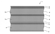
- a porous liner 2 and a low-density elastic porous body layer 3 are formed from the surface on the sound source side to the outer surface side when installed.
- a low-frequency sound-absorbing layer 4 a first high-frequency sound-absorbing layer 7a composed of a high-density elastic porous body layer 6 covered with soft sound-insulating films 5 and 5 that are low-breathable sheets, and a low-breathable sheet.
- the second high-frequency sound-absorbing layer 7b composed of the high-density elastic porous body layer 6 covered with the soft sound-insulating films 5 and 5
- the soundproof cover 1 composed of a laminated material in which the exterior material sheet 8 is sequentially laminated.
- the soundproof cover includes a low-circumference composed of a porous liner 2 and a low-density elastic porous body layer 3 from the sound source side during installation to the outer surface side.
- a first sound-absorbing layer 7a comprising a laminate of a sound-absorbing layer 4, a porous liner 2 and a high-density elastic porous body layer 6 covered with soft sound-insulating films 5 and 5 which are low-breathable sheets, It consists of a laminated material in which a second high-frequency sound-absorbing layer 7b composed of a high-density elastic porous body layer 6 covered with a soft sound-insulating film 5 and 5 that is a low-breathable sheet, and an exterior material sheet 8 are sequentially laminated.
- the soundproof cover 1 can be mentioned.
- the low-density elastic porous body layer (low-density elastic porous body layer 3 illustrated in FIGS. 2 and 3) is made of a low-density elastic porous body and has a density thereof.
- the density is appropriately selected from those capable of absorbing low-frequency sound according to the structure and thickness of the low-density elastic porous body layer.
- the low density elastic porous body layer is preferably composed of a low density elastic porous body having a basis weight of 50 to 1,000 g / m 2 and a basis weight of 100. It is more preferable that is composed of a low density resilient porous material which is a ⁇ 500g / m 2, and still more preferably composed of a low density elastic porous body weight per unit area is 250 ⁇ 500g / m 2.
- a lightweight and soundproof cover having a desired shape can be easily obtained.
- the density of the low density elastic porous body layer and the weight per unit area of the low density elastic porous body constituting the low density elastic porous body layer are within the above range, thereby reducing weight and compactness.
- examples of the low density elastic porous material constituting the low density elastic porous material layer include one or more selected from fiber assemblies, felts, and resin foams.
- Examples of the fiber assembly include one or more selected from sprayed or molded products of artificial mineral fibers such as glass wool and rock wool.
- Examples of the felt include polyester fiber felt such as polyethylene terephthalate felt, nylon fiber felt, polyethylene fiber felt, polypropylene fiber felt, acrylic fiber felt, silica-alumina ceramic fiber felt, sili-force fiber felt, cotton, wool, wood wool, scraps
- polyester fiber felt such as polyethylene terephthalate felt, nylon fiber felt, polyethylene fiber felt, polypropylene fiber felt, acrylic fiber felt, silica-alumina ceramic fiber felt, sili-force fiber felt, cotton, wool, wood wool, scraps
- resin felt or the like obtained by processing fibers or the like into a felt with a thermosetting resin can be given.
- resin foam one or more selected from resin foams such as polyurethane foam, polyethylene foam, polypropylene foam, phenol foam, melamine foam, nitrile butadiene rubber, chloroprene rubber, styrene rubber, silicone rubber, urethane rubber, ethylene -One or more types selected from open-cell bodies obtained by foaming propylene / diene rubber or the like in the form of open cells, or foamed by foaming after crushing or the like can be mentioned.
- resin foams such as polyurethane foam, polyethylene foam, polypropylene foam, phenol foam, melamine foam, nitrile butadiene rubber, chloroprene rubber, styrene rubber, silicone rubber, urethane rubber, ethylene -One or more types selected from open-cell bodies obtained by foaming propylene / diene rubber or the like in the form of open cells, or foamed by foaming after crushing or the like can be mentioned.
- the soundproof cover according to the present invention includes one or more low-density elastic porous layers, and may usually include about one to three layers. However, in order to reduce weight and size (as illustrated in FIG. 2 or FIG. 3). As such, it is preferable to include one layer of a low-density elastic porous material layer.
- the thickness of the low density elastic porous material layer is preferably 2.5 to 20 mm, more preferably 2.5 to 10 mm, and further preferably 2.5 to 5 mm.
- the soundproof cover according to the present invention includes a plurality of low density elastic porous body layers
- the total thickness of the plurality of low density elastic porous body layers may be within the above range.
- the thickness of the low-density elastic porous body is within the above range, it can be easily made compact (thinned). Can also be suitably used as a soundproof cover for oil pans.
- the low density elastic porous body layer is preferably composed of a low density elastic porous body having a Young's modulus of 5 to 20 kPa, and a low density having a Young's modulus of 6 to 17 kPa. More preferably, it is made of an elastic porous material, and more preferably, it is made of a low density elastic porous material having a Young's modulus of 8 to 16 kPa. Since the low-density elastic porous body layer is composed of the low-density elastic porous body having the above Young's modulus, the low-density elastic porous body layer easily exhibits excellent flexibility (a spring constant described later). Be small enough). In this application document, the Young's modulus means a value measured in accordance with JIS K 7127.
- the low density elastic porous body layer is preferably provided on the installation object side (sound source side) such as an oil pan than the high density elastic porous body layer at the time of installation. More preferably, it is provided in close contact with the object (sound source).
- the low-density elastic porous body directly supports the installation object side (sound source side), effectively suppressing the emission of sound into the air, and its excellent flexibility Depending on the nature, it is possible to effectively attenuate the sound in the low frequency range of 400 to 800 Hz caused by the solid propagation sound (vibration).
- the low-density elastic porous material layer is a sound-absorbing layer for low-frequency sound of 400 to 800 Hz exclusively of solid propagation sound (vibration). Function as.
- the low-density elastic porous body layer is a so-called resonance that repeats vibration deformation, particularly for transverse wave propagation sound, among solid propagation sound (vibration) propagating from an installation object such as a vehicle-oriented oil pan. It is considered that a phenomenon occurs, and an attenuator (damper) effect resulting from mechanical energy loss is generated, so that sound in a low frequency range of 400 to 800 Hz can be effectively attenuated exclusively.
- the high-density elastic porous body layer (the high-density elastic porous body layer 6 illustrated in FIGS. 2 and 3) is made of a high-density elastic porous body and has a density of There is 0.125 ⁇ 1.000g / cm 3, preferably from 0.125 ⁇ 0.500g / cm 3, more preferably 0.125 ⁇ 0.200g / cm 3.
- the density is appropriately selected from those capable of absorbing high-frequency sound according to the structure and thickness of the high-density elastic porous body layer.
- the high-density elastic porous body layer is preferably composed of a high-density elastic porous body having a basis weight of 500 to 3,000 g / m 2 and a basis weight of 500 it is more preferable that is composed of a high-density elastic porous body is ⁇ 2,000g / m 2, the basis weight is constituted by a high-density elastic porous member is 500 ⁇ 1,500g / m 2 Is more preferable.
- the basis weight of the low density elastic porous body is within the above range, a lightweight soundproof cover can be easily obtained.
- examples of the high-density elastic porous material constituting the high-density elastic porous material layer include one or more selected from fiber assemblies, felts, and resin foams, and specific examples thereof. Examples thereof include the same as the low-density elastic porous body constituting the low-density elastic porous body layer described above.
- the soundproof cover according to the present invention includes one or more high-density elastic porous layers, and may usually include one to six layers. However, in order to reduce weight and size, one layer of the high-density elastic porous layers is required. Alternatively, those including two layers are preferable, and specifically, those including two layers of the high-density elastic porous body layer 6 as shown in FIG. 2 or 3 can be exemplified.
- the thickness of the high-density elastic porous body layer is preferably 2.5 to 50 mm, more preferably 2.5 to 20 mm, and still more preferably 5 to 10 mm.
- the soundproof cover according to the present invention includes a plurality of high-density elastic porous material layers, the total thickness of the plurality of high-density elastic porous material layers may be within the above range.
- the thickness of the high-density elastic porous material is within the above range, it can be easily made compact (thinned). Can also be suitably used as a soundproof cover for oil pans.
- the high-density elastic porous material layer is preferably composed of a low-density elastic porous material having a Young's modulus exceeding 20 kPa, and a high-density having a Young's modulus exceeding 20 kPa to 2000 kPa. More preferably, it is made of an elastic porous material, and more preferably, it is made of a high-density elastic porous material having a Young's modulus of more than 20 kPa to 1000 kPa. Since the high-density elastic porous body layer is composed of the high-density elastic porous body having the Young's modulus, a predetermined shape can be easily maintained with an appropriate rigidity.
- Young's modulus means the value measured based on prescription
- the high-density elastic porous body layer is covered with a low-breathable sheet such as the soft sound-insulating film 5 illustrated in FIGS.
- examples of the low breathability sheet include one or more selected from a soft sound insulation film, an exterior material sheet (sheet-like cover installed on the outer surface side at the time of installation) and the like described later.
- a soft sound insulation film is preferable.
- the low-breathable sheet disposed on the outer surface side is used as the exterior material sheet, and is disposed on the inner side (sound source side).
- the low-breathable sheet can also be a soft sound insulation film.
- the soundproof cover according to the present invention as the soft sound insulation film, the sound that has deformed itself and attenuated the sound transmitted through the high-density elastic porous material layer is attenuated, and the high-density elastic porous material layer is sealed so-called air radiation. There is no particular limitation as long as the sound can be attenuated and reduced.
- the low air-permeable sheet has an air permeability of 10 cc / cm 2 ⁇ sec or less, preferably 0.001 to 10 cc / cm 2 ⁇ sec, preferably 0.01 to 1 cc / cm More preferably, it is cm 2 ⁇ sec.
- the sound insulation property of the sound insulation layer composed of the high-density elastic porous body layer can be enhanced by the air permeability of the low air permeability sheet being 10 cc / cm 2 ⁇ sec or less.
- aeration volume shall mean the value measured based on JISL1018.
- the low air-permeable sheet is preferably made of a material that is flexible enough to be deformed by vibration of sound, and has a Young's modulus of 0.001 to 0.5 GPa, preferably 0.02 to What is 0.1 GPa is more preferable.
- Young's modulus shall mean the value measured based on JISK7127.
- the Young's modulus of the soft sound insulating film is 1/5 of the Young's modulus of the exterior material sheet described later. Or less, more preferably 1/10 or less.
- the sound wave transmitted through the low-density elastic porous body layer selectively selects the soft sound-insulating film coated around the high-density elastic porous body layer. Sound insulation is increased by the vibrational deformation, and sound waves attenuated by the soft sound insulation film are absorbed by the high-density elastic porous body layer and further sound-insulated by the exterior material sheet provided as appropriate. The performance can be further improved.
- Examples of the soft sound insulating film include a resin film and the like, and can be appropriately selected from those having a predetermined Young's modulus and air flow rate.
- the soundproof cover according to the present invention includes a high-density elastic porous material layer
- the high-density elastic porous material layer functions as a sound-absorbing layer for solid-propagating sound (vibration) and originates exclusively from air radiation sound. It functions as a sound absorbing layer in a high frequency range exceeding 800 Hz.
- the high-density elastic porous body layer is a so-called resonance that repeats vibration deformation, particularly for transverse wave propagation sound, among solid propagation sound (vibration) propagating from an installation object such as a vehicle-oriented oil pan.
- Examples of the soundproof cover according to the present invention include a low-density elastic porous material layer, and a low-density elastic porous material layer. What consists of a laminated body in which the body layer is one layer and the high-density elastic porous body layer is laminated in two layers is preferable.
- the soundproof cover according to the present invention one or two layers of low-density elastic porous material layers and one or two layers of high-density elastic porous material layers are laminated from the sound source side during installation to the outer surface side.
- One layer of low-density elastic porous material layer and two layers of high-density elastic porous material layer are laminated from the surface on the sound source side to the outer surface side during installation.
- the soundproof cover As the soundproof cover according to the present invention, one or two layers of high-density elastic porous material layer, one layer of low-density elastic porous material layer, from the surface that becomes the sound source side during installation to the outer surface side,
- the soundproof cover include a layered body in which the density elastic porous body layer is laminated in one layer or two layers. Such a soundproof cover has a high density from the surface on the sound source side to the outer surface side during installation.
- the laminated material constituting the soundproof cover according to the present invention preferably has a porous liner (porous liner 2 in the examples shown in FIGS. 2 and 3) on the surface that becomes the sound source when installed.
- the porous liner means one that functions as a backing layer for adhering to the installation surface at the time of installation, and preferably has water repellency or oil repellency.
- a porous liner for example, One or more selected from non-woven fabrics and thermoplastic resin films can be mentioned.
- thermoplastic film examples include polyamide resin film, polyester resin film, polyolefin resin film, soft vinyl chloride resin film, polyvinyl alcohol resin film, polycarbonate resin film, polystyrene resin film, and polyacrylonitrile.
- resin films ethylene-vinyl acetate copolymer resin films, and the like can be given.
- thermoplastic resin films it is preferable to use a polyamide-based resin film excellent in toughness, impact resistance, and flexibility.
- the thermoplastic resin film may be either a stretched film or an unstretched film.
- a laminated material obtained by laminating a forming material corresponding to each constituent member is hot press-molded into a predetermined shape to produce a soundproof cover.
- the film is an unstretched film in consideration of moldability.
- the unstretched film is preferably stretchable at an elongation of 5 to 500%, more preferably stretchable at an elongation of 10 to 500%. More preferably, the film can be stretched at 20 to 200%.
- the stretch rate of the unstretched film was determined by performing a tensile test in accordance with JIS K7161, and when a strip-shaped test piece having a width of 25 mm ⁇ a length of 150 mm was pulled at a speed of 100 mm / min, the load reached 10 N. It means the elongation percentage of the film at the time.
- an adhesive layer made of an adhesive such as a polyurethane elastomer film, a polyolefin blend elastomer film, a polyolefin copolymer elastomer film, a polystyrene copolymer elastomer film, or a polyester copolymer elastomer film may be laminated.
- the soundproof cover of the present invention has a thermoplastic resin film as the porous liner, it is possible to suppress intrusion of rainwater and the like from the installation surface into the interior, and a low density elastic porous body layer or a high density elastic porous It is possible to suppress deterioration of the body layer and the like due to water absorption and a decrease in sound absorption performance.
- the laminated material constituting the soundproof cover according to the present invention is preferably one in which an exterior material sheet is laminated on a surface which becomes the outer surface side at the time of installation.
- the exterior material sheet include a resin sheet and a metal sheet.
- the exterior material sheet a plurality of resin sheets or metal sheets may be laminated and combined via an adhesive layer or the like.
- the exterior material sheet a reinforcing cloth and a skin film are sequentially laminated and combined. It may be converted.
- the exterior material sheet is preferably made of a resin sheet.
- the exterior material sheet preferably has a ventilation rate of 10 cc / cm 2 ⁇ sec or less, more preferably 0.001 to 10 cc / cm 2 ⁇ sec, More preferably, it is ⁇ 1 cc / cm 2 ⁇ sec.
- the sound insulation layer made of the high-density elastic porous body layer is disposed on the inside of the exterior material sheet by the air flow rate of 10 cc / cm 2 ⁇ sec or less, the sound insulation is provided. Can be easily enhanced.
- the air flow rate means a value measured in accordance with JIS L1018.
- the exterior material sheet is a metal sheet
- the metal constituting the metal sheet include stainless steel.
- the resin constituting the resin sheet includes polypropylene resin, nylon 6, nylon 66, nylon 11, nylon 12, nylon 610, nylon 612, and other polyamide resins, acrylic resin, and polyfluoride.
- Fluorine resin such as vinylidene fluoride resin, polytetrafluoroethylene resin, polyester resin such as polyethylene terephthalate, diallyl phthalate resin, bismaleimide triazine resin, phenol resin, urea resin, melamine resin, epoxy resin, polystyrene resin, ABS resin, polychlorinated Vinyl resin, methacrylic resin, polyamideimide resin, polyisobutylene resin, polycarbonate resin, polyphenylene oxide resin, polyphenylene sulfide resin, polyacetal resin, polyether It can be exemplified one or more selected from sulfone resin.
- the reinforcing cloth include those made of various woven fabrics, for example, polyolefin-based materials such as polypropylene-based resin fibers. Woven made by weaving one or more fibers selected from thermoplastic resin fibers such as resin fibers, polyester resin fibers, polyamide resin fibers, soft vinyl chloride resins, polycarbonate resin fibers, and polyacrylonitrile resin fibers. Mention may be made of cloth.
- the reinforcing cloth for example, when the soundproof cover according to the present invention is produced by hot press molding a laminate of forming materials corresponding to each constituent member into a predetermined shape, the formability and after molding
- a woven fabric obtained by weaving one or more fibers selected from polypropylene resin fibers, polyester resin fibers, polyamide resin fibers and the like are preferable.
- the woven fabric may be a woven fabric woven by plain weaving, twill weaving, etc., but the soundproof cover according to the present invention heat-molds a laminate of forming materials corresponding to each constituent member into a predetermined shape.
- those made of a woven fabric having stretchability woven by a 2-way tricot weave are preferable.
- the skin film includes the same thermoplastic resin film as exemplified in the description of the porous liner described above. be able to.
- an adhesive layer or the like may be interposed as necessary.
- the reinforcing cloth is laminated by adhering to the high-density elastic porous body layer (high-frequency sound absorbing layer) side.
- an adhesive made of an adhesive selected from a polyurethane elastomer film, a polyolefin blend elastomer film, a polyolefin copolymer elastomer film, a polystyrene copolymer elastomer film, a polyester copolymer elastomer film, etc. Layers may be stacked.
- a reinforcing cloth is formed when a soundproof cover is produced by hot-pressing a laminate in which a forming material corresponding to each constituent member is laminated.
- the fibers of the woven fabric to be melted are melted, and after molding, the fibers are cooled and solidified in a state of being molded into a predetermined shape, and the fibers are fixed to each other, whereby the rigidity is increased and the shape after molding is well maintained.
- the cooling water handled in the engine room LLC
- durability against battery fluid window washer fluid, etc.
- heat resistance against engine heat oil resistance against oils and fats
- durability against external environment such as wind and rain, stepping stones, etc. It can be used over a long period of time while suppressing deterioration over time even under a severe use environment.
- the Young's modulus of the sheet material for forming the exterior material sheet (which becomes the material for forming the exterior material sheet) before molding is 0 It is preferably 0.005 GPa to 0.5 GPa, more preferably 0.05 GPa to 0.3 GPa, and the Young's modulus of the exterior material sheet (after molding) is 0.6 GPa to 5.0 GPa. Preferably, it is 1.0 GPa to 3.0 GPa.
- Young's modulus shall mean the value measured based on JISK7127.
- the soundproof cover according to the present invention is a so-called resonance in which the low-density elastic porous body layer repeats vibration deformation, particularly with respect to transverse wave propagation sound, among solid propagation sound (vibration) propagating from an object to be disposed such as an oil pan for a vehicle. It is considered that a phenomenon occurs, and an attenuator (damper) effect resulting from mechanical energy loss is generated, so that sound in a low frequency range of 400 to 800 Hz can be effectively attenuated exclusively.
- the high-density elastic porous body layer functions as a sound absorption layer for solid propagation sound (vibration), and as a sound absorption layer in a high frequency range exceeding 800 Hz caused exclusively by air radiation sound. Function.
- the high-density elastic porous body layer is a so-called resonance that repeats vibration deformation, particularly for transverse wave propagation sound, among solid propagation sound (vibration) propagating from an installation object such as a vehicle-oriented oil pan.
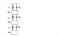
- the sound absorbing effect in the soundproof cover of the present invention will be described as follows, taking the soundproof cover 1 shown in FIGS. 2 and 3 as an example. That is, when the soundproof cover 1 shown in FIGS. 2 and 3 is replaced with a spring-mass model, as shown schematically in FIG. 4, the low-density elastic porous body layer 3 is disposed on the solid propagation sound incident side.
- a low-frequency sound-absorbing layer 4 constitutes a spring I (spring constant ⁇ 1 , mass m 1 ) having a small spring constant together with the adjacent porous liner 2 and soft sound-insulating film 5, and is composed of a high-density elastic porous body layer 6.
- An air spring II (spring constant ⁇ 2 , mass m 2 ) together with a two-layer soft sound insulating film 5 (and a porous liner 2 in the example shown in FIG. 3) in which one high-frequency sound-absorbing layer 7a is disposed above and below.
- the air spring III (spring constant ⁇ 3 , mass) together with the two layers of the soft acoustic insulation film 5 and the exterior material sheet 8 in which the first high-frequency sound-absorbing layer 7b composed of the high-density elastic porous body layer 6 is arranged vertically.
- a multi-degree-of-freedom spring mass system is formed by connecting springs I, II and III in series.
- the spring I, the spring II and the spring III are each an attenuator (damper) caused by mechanical energy loss due to vibration propagation of the elastic porous material skeleton expressed by the Biot model, particularly vibration deformation during transverse wave propagation. And dampening d 1 , d 2 and d 3 , respectively, but in particular the spring I is loaded with the total mass (m 1 + m 2 + m 3 ) of the soundproof cover to produce a large dampening action d 1 It is considered that a so-called resonance phenomenon that repeats vibration deformation is particularly likely to occur among solid propagation sound (vibration) propagating from an installation object such as an oil pan, and the spring II and the spring III are soft. Since it is covered and sealed with a sound insulation film, it acts as a so-called air spring that utilizes the elasticity of compressed air and demonstrates the vibration insulation effect of the air spring. It is believed to suppress the vapor emission sound.
- ⁇ is the spring constant of each spring
- m means the mass of the weight loaded on the spring
- the spring I, spring II and spring III also constitute each spring.
- the 2 and 3 has a small spring constant because the low-density elastic porous body layer constituting the spring part I is superior in flexibility compared to the springs II and III, and Considering that the mass (m 1 + m 2 + m 3 ) to be loaded is larger than that of the spring II and the spring III, the natural frequency (resonance frequency) becomes small, and sound in a low frequency range can be effectively attenuated. It is done.
- the soundproof cover according to the present invention can be suitably used as a soundproof cover for components of various vehicles.
- a sound source such as an oil pan installed around an engine installed in an engine room of an automobile, particularly on the lower surface of the engine. It can be suitably used for soundproofing by adjoining or closely adhering to the facility, for example, as shown in FIG. 1, the soundproofing that can be used by being disposed so as to cover the surface of the oil pan as a sound source
- a cover 10 can be provided.
- the soundproof cover according to the present invention can be manufactured, for example, by hot-press molding into a predetermined shape in a state where all of the forming materials corresponding to the constituent members of the soundproof cover to be obtained are sequentially laminated.
- the soundproof cover according to the present invention can be obtained, for example, by heat-pressure molding into a predetermined shape in a state in which only a part of all the forming materials corresponding to the constituent members of the soundproof cover to be obtained is sequentially laminated. It is possible to produce a material obtained by heat-pressing a predetermined shape in a state in which other forming materials corresponding to the constituent members of the soundproof cover are sequentially laminated with an adhesive or the like.
- a soundproof cover for example, when producing a soundproof cover shown in FIG. 2, (1) a porous liner, (2) a low density elastic porous body, (3) a soft sound insulating film, (4) A high-density elastic porous body, (5) a soft sound insulation film, (6) a high-density elastic porous body, (7) a soft sound insulation film, and (8) a forming material for forming an exterior material sheet in this order. It can be manufactured by hot pressing into a predetermined shape in the state of being sequentially laminated.
- (1) a porous liner, (2) a low-density elastic porous body, and (3) a forming material for forming a soft soundproof film An integrated product for forming a low-frequency sound-absorbing layer obtained by hot-press molding in the state of being sequentially laminated in this order, (4) high-density elastic porous material, (5) soft sound-insulating film, (6) high-density An integrated body for forming a high-frequency sound-absorbing layer, which is obtained by hot-pressure molding in a state in which a forming material for forming an elastic porous body, (7) a soft sound insulation film, and (8) an exterior material sheet is sequentially laminated in this order; By fixing the (3) soft sound insulation film side of the low-frequency sound-absorbing layer forming integrated body and the (4) high-density elastic porous body side of the high-frequency sound-absorbing layer forming integrated body with an adhesive or the like. Can be produced.
- a porous liner for example, (1) a porous liner, (2) a low-density elastic porous body, and (3) a forming material that forms a soft sound-insulating film are used.
- the integrated material for forming the sound absorbing layer is bonded to the (3) soft sound insulating film side of the integrated material for forming the low frequency sound absorbing layer and the (1) porous liner side of the integrated material for forming the high frequency sound absorbing layer. It can produce by fixing with.
- the forming material of the low density elastic porous body is excessively pressed and has a desired density. It may be difficult to form a low-density elastic porous body layer having a low-frequency sound-absorbing layer forming integrated material and a high-frequency sound-absorbing layer forming integrated material separately as described above.
- the obtained hot-press molded product is fixed with an adhesive or the like, it is possible to easily form a low-density elastic porous body layer and a high-density elastic porous body layer each having a desired density. it can.
- an immobilization product in which a part or all of the forming material corresponding to the constituent member of the soundproof cover to be obtained is fixed in advance with an adhesive or the like is arranged and heated to a predetermined shape. It may be formed by pressure molding, or it may be produced by simply hot-pressing a part or all of the forming material corresponding to the structural member of the soundproof cover to be obtained in the molding die into a predetermined shape in a state of being sequentially laminated. May be.
- the above (7) soft sound insulation film and (8) exterior material sheet may be formed by hot pressing by laminating fixed materials in which the respective forming materials are integrated in advance by laminating or the like. Hot pressing may be performed.
- the vertical and horizontal lengths of the (3) soft sound insulation film, (5) soft sound insulation film, and (7) soft sound insulation film are respectively (4) high-density elastic porous body and (6) high-density It is preferable that the length of the elastic porous body forming material is larger than the vertical and horizontal lengths, and a high-density elastic porous body is formed by using such a soft sound-insulating film and press-bonding by hot-pressure molding or bonding with an adhesive. It is possible to sufficiently cover up to the periphery (end).
- the applied pressure at the time of hot-press forming is preferably 3 to 50 MPa, more preferably 3 to 30 MPa. More preferably, the atmospheric temperature at the time of hot pressing is preferably from 120 to 200 ° C, more preferably from 140 to 200 ° C, further preferably from 160 to 180 ° C, and the pressing time at the hot pressing is from 3 to 60 seconds is preferred, 5 to 45 seconds is more preferred, and 10 to 30 seconds is even more preferred.
- one or more low-weight and soft low-density elastic porous material layers are used as the low-frequency sound-absorbing layer, and the light-weight and soft high-density elastic porous material is coated with a soft sound-insulating film as the high-frequency sound-absorbing layer.
- One or more material layers are laminated, and the low-frequency sound absorbing layer can attenuate sound in a low frequency range of 400 to 800 Hz caused solely by solid-propagating sound (vibration), and the high-frequency sound absorbing layer can be solid-propagated.
- a lightweight and soft soundproof cover capable of suppressing sound in a high frequency region exceeding 800 Hz and effectively suppressing sound in a low frequency region of 400 Hz to 800 Hz. Can do.
- Example 1 Porous liner forming material (weight per unit area 127 g / m 2 , thickness) in a mold provided with a molding surface corresponding to the target shape to be obtained (arranged on the sound source side during installation) 1.5 mm water- and oil-repellent treated polyester short fiber nonwoven fabric), 30 g of an adhesive (moisture-curable polyurethane hot melt) is uniformly applied thereon, and then (2) low density Elastic porous body forming material (weight per unit area 250 g / m 2 , polyethylene terephthalate short fiber felt having a thickness of 10 mm), (3) Soft sound insulating film A forming material (unit weight 38 g / m 2 , thickness 30 ⁇ m, air flow rate) polyurethane elastomer film 0cc / cm 2 ⁇ sec), (4) high-density elastic porous body I of the forming material (basis weight 500 g / m 2, a thickness of 5mm polyethylene terephthalate short fiber felt) (5)
- the soundproofing property of the soundproofing cover obtained by the following method was evaluated.
- the porous liner side of the soundproof cover is placed in close contact with a test specimen steel plate (150 mm long, 150 mm wide, 3 mm thick steel plate), and the vibrator (Bruel Care Japan, Inc.) is applied to the test steel plate.
- White noise (white noise) is input by type 4809), and a sound of 400 Hz to 10 kHz is generated at a 1/3 octave band frequency, and a microphone (1/2 inch condenser microphone) placed 150 mm away from the soundproof cover
- the change in sound pressure level (dB) was measured.
- the soundproofness was evaluated by determining the difference between the case where the soundproof cover was not disposed and the case where the soundproof cover was disposed.
- the results are shown in FIG.
- the obtained soundproof cover had a soundproof effect (sound pressure reduction effect) of about 11 dB at 400 Hz, about 13 dB at 500 Hz, about 3 dB at 630 Hz, and about 8 dB at 800 Hz.
- the obtained soundproof cover for comparison has an increased sound pressure level of about 8 dB at 400 Hz, about 6 dB at 500 Hz, about 3 dB at 630 Hz, and about 4 dB at 800 Hz.
- the noise in the frequency range of 400 Hz to 800 Hz was increased.
- Comparative Example 2 Polyurethane 6 (weight per unit area 2,400 g / m 2 , thickness) as a rigid sound insulation material on a foamed urethane foam with a double-sided skin layer (located on the sound source side during installation) (weight per unit area 3,400 g / m 2 , thickness 20 mm) 2 mm) was attached to obtain a comparative soundproof cover having a thickness of 22 mm and a basis weight of 5,800 g / m 2 . The soundproofing property was evaluated in the same manner as in Example 1 using the obtained comparative soundproofing cover. The results are shown in FIG. As shown in FIG.
- the obtained soundproof cover for comparison has a sound pressure level of about 7 dB at 400 Hz, about 3 dB at 500 Hz, about 0 dB at 630 Hz, and about 7 dB at 800 Hz.
- the comparative soundproof cover obtained has a mass (weight per unit area) that is at least three times that of the soundproof cover obtained in Example 1.
- the thickness increases, it is difficult to reduce the weight and size of the soundproof cover.
- Table 1 shows the results of Example 1, Comparative Example 1, and Comparative Example 2.
- the soundproof cover obtained in Example 1 is coated with a light and soft low density elastic porous body layer as a low frequency sound absorbing layer and a soft sound insulating film as a high frequency sound absorbing layer.
- Lightweight and soft high-density elastic porous body layer is laminated, and it is lightweight and compact (thin), and the low-frequency sound absorbing layer has a low frequency of 400 to 800 Hz caused exclusively by solid-borne sound (vibration). It can be seen that the low-frequency sound can be effectively attenuated, and the high-frequency sound-absorbing layer can attenuate the high-frequency sound exceeding 800 Hz caused solely by the air radiation sound together with the solid propagation sound.
- the comparative soundproof cover obtained in Comparative Example 1 does not have a low-density elastic porous body layer, and therefore has a low frequency of 400 to 800 Hz caused by solid sound propagation (vibration). Since the sound in the frequency range cannot be attenuated and the comparative soundproof cover obtained in Comparative Example 2 has neither a low-density elastic porous body layer nor a high-density elastic porous body layer, It can be seen that it is difficult to reduce the weight and size of the cover.
- a lightweight and thin soundproof cover that can suppress a sound in a high frequency region exceeding 800 Hz and can effectively suppress a sound in a low frequency region of 400 Hz to 800 Hz.
Landscapes
- Engineering & Computer Science (AREA)
- Physics & Mathematics (AREA)
- Multimedia (AREA)
- Acoustics & Sound (AREA)
- Chemical & Material Sciences (AREA)
- Transportation (AREA)
- Mechanical Engineering (AREA)
- Combustion & Propulsion (AREA)
- Structural Engineering (AREA)
- Architecture (AREA)
- Laminated Bodies (AREA)
- Soundproofing, Sound Blocking, And Sound Damping (AREA)
- Body Structure For Vehicles (AREA)
Abstract
800Hzを超える高周波数領域の音を抑制するとともに、400Hz~800Hzの低周波数領域の音を効果的に抑制し得る、軽量でかつ薄形の防音カバーを提供する。 密度0.005~0.100g/cm3の低密度弾性多孔質体層が一層以上と、通気量が10cc/cm2・sec以下である低通気性シートで周囲を被覆された密度0.125~1.000g/cm3の高密度弾性多孔質体層が一層以上積層された積層材からなることを特徴とする防音カバーである。
Description
本発明は、防音カバーに関する。
従来より、自動車のエンジンなどを発生源とする騒音を軽減するために、種々の防音材が提案されている。例えば、本出願人は、音源に対向して配置される吸音材と、吸音材に積層される非通気性の軟質遮音層と、軟質遮音層との間で空気層を形成する軟質カバーとを備え、空気層を密封してなる防音カバーを提案している(特許文献1(特開平2011-64167号公報)参照)。
ところで、国連の欧州経済委員会(ECE)の自動車基準調和世界フォーラムにおいては、自動車騒音に関する基準調和についての検討がなされており、上記フォーラムにおいては、車両の構造に関する規則の制定、改訂が行われ、その規則51(ECE R51)に自動車の車外騒音の規制値が定められている。
近年、上記自動車の車外騒音の規制値は、規則の改訂がなされるたびに厳しくなってきており、Regulation EU No.540/2014によると、2016年7月時点で72dB、2020年7月時点で70dB、2024年7月時点で68dBと段階を追って厳しい基準が施行されることになっており、最終的に2016年7月時点の基準に対して4dBの低減、音圧エネルギーでは約1/2.5に低減することが求められるようになっている。
上述したように近年益々厳しくなってきている車外騒音低減の要求に応えるには、従前は防音対策が講じられてこなかった騒音源、例えば、エンジン下面側オイルパンなどのようなエンジン下回りの音源に防音対策を講じることが考えられる。
しかしながら、オイルパンには燃焼圧変動、動弁系負荷、燃料高圧噴射等の燃焼系、クランクシャフトねじり振動、フライホイール面振れ振動、エンジンブロック構造共振等の回転系より伝搬した振動に加え、オイル散布による直接打音等の大きな振動入力が加わり、通常カチオンメッキ鋼板や樹脂を成形して製造されるオイルパンからは、これら振動伝搬に起因する大きな固体伝搬音が発生し、この固体伝搬音は、通常問題となる1,000Hz~5,000Hzの周波数域の騒音とともに、複素音圧振幅が大きいために防音対策が困難である400Hz~800Hzの周波数域の騒音を含み、この400Hz~800Hzの周波数域の騒音対策が求められる。
上記400Hz~800Hzの比較的低周波数域の遮音対策として、高質量・高剛性遮音材を用いた防音カバーを使用することが考えられる。
すなわち、防音カバーとして、振動入力に対する剛性遮音材の変形のしにくさが遮音性能に比例すること(質量則)と、エネルギー入射面に対し背面側となる剛体遮音材と音源の間に配置された多孔質吸音材が、膜振動系吸音材或いは動吸振器として一般に知られる共振現象を利用した吸音機構により、吸音材の面密度及び厚さから計算される、比較的低周波数域に吸音ピークを生じることを利用したものが考えられる。
すなわち、防音カバーとして、振動入力に対する剛性遮音材の変形のしにくさが遮音性能に比例すること(質量則)と、エネルギー入射面に対し背面側となる剛体遮音材と音源の間に配置された多孔質吸音材が、膜振動系吸音材或いは動吸振器として一般に知られる共振現象を利用した吸音機構により、吸音材の面密度及び厚さから計算される、比較的低周波数域に吸音ピークを生じることを利用したものが考えられる。
このような防音カバーとして、例えば、対策周波数800Hz用に厚さ2mmの剛性遮音材ポリアミド6と、密度170kg/m3、厚さ20mmの多孔質吸音材ポリウレタンフォームを組み合わせた構造材からなる防音カバーが考えられるが、係る構造体においては1m2あたりの質量が5,800gとなり、これに対して特許文献1記載の防音カバーは、例えば1m2あたりの質量が1,400gと軽量であることから、大幅な質量増加は免れない。
近年の低燃費化の開発動向を考慮した場合、防音カバーの質量増加は許容され難い。
近年の低燃費化の開発動向を考慮した場合、防音カバーの質量増加は許容され難い。
一方、特許文献1の防音カバーは、400Hz~800Hzの比較的低周波数域の固体伝搬音対策が必ずしも十分でなく、むしろBiotモデルで表現されるカバー本体(弾性多孔質材)の振動変形による機械的エネルギー損失を原理とするものであることから、よりエネルギーの大きな固体伝搬音が入力されカバーが大きく動くために、この周波数領域の騒音が悪化する傾向にある。
近年において、軽量・コンパクト化は時代の流れであり、軽量でかつ軟質な防音カバーは、高密度に集積したエンジンルーム内の周辺部品の配置に合わせて形状修正が容易でありかつ周辺部品と多少干渉しても自らが変形することで周辺部品に破損等を生じにくいこともあり、固体伝搬音対策を強化した新たな軽量・軟質防音カバーが求められるようになっている。
このような状況下、本発明は、800Hzを超える高周波数領域の音を抑制するとともに、400Hz~800Hzの低周波数領域の音を効果的に抑制し得る、軽量でかつ薄形の防音カバーを提供することを目的とするものである。
上記目的を達成するために、本発明者等が鋭意検討を行った結果、密度0.005~0.100g/cm3の低密度弾性多孔質体層が一層以上と、通気量が10cc/cm2・sec以下である低通気性シートで周囲を被覆された密度0.125~1.000g/cm3の高密度弾性多孔質体層が一層以上積層された積層材からなる防音カバーにより、上記目的を達成し得ることを見出し、本知見に基づいて本発明を完成するに至った。
すなわち、本発明は、
(1)密度0.005~0.100g/cm3の低密度弾性多孔質体層が一層以上と、通気量が10cc/cm2・sec以下である低通気性シートで周囲を被覆された密度0.125~1.000g/cm3の高密度弾性多孔質体層が一層以上積層された積層材からなることを特徴とする防音カバー、
(2)前記低密度弾性多孔質体層を構成する低密度弾性多孔質体および前記高密度弾性多孔質体層を構成する高密度弾性多孔質体の少なくも一種が、繊維集成体、フェルトおよび樹脂発泡体から選ばれる一種以上である上記(1)に記載の防音カバー、
(3)前記低通気性シートが軟質遮音フィルムである上記(1)または(2)に記載の防音カバー、
(4)前記低密度弾性多孔質体層を一層、前記高密度弾性多孔質体層を二層有する上記(1)~(3)のいずれかに記載の防音カバー、
(5)設置時に音源側となる面から外表面側に向かって、前記低密度弾性多孔質体層からなる低周波音吸音層、前記低通気性シートで周囲を被覆された高密度弾性多孔質体層からなる第一の高周波音吸音層、前記低通気性シートで周囲を被覆された高密度弾性多孔質体層からなる第二の高周波音吸音層が順次積層された積層材からなる上記(1)~(4)のいずれかに記載の防音カバー、
(6)設置時に音源側となる面から外表面側に向かって、多孔質ライナー、前記低密度弾性多孔質体層からなる低周波音吸音層、前記軟質遮音フィルムで周囲を被覆された高密度弾性多孔質体層からなる第一の高周波音吸音層、前記軟質遮音フィルムで周囲を被覆された高密度弾性多孔質体層からなる第二の高周波音吸音層、外装材シートが順次積層された積層材からなる上記(3)~(5)のいずれかに記載の防音カバー、
(7)設置時に音源側となる面から外表面側に向かって、多孔質ライナー、前記低密度弾性多孔質体層からなる低周波音吸音層、前記軟質遮音フィルムで周囲を被覆された多孔質ライナーおよび高密度弾性多孔質体層の積層物からなる第一の高周波音吸音層、前記軟質遮音フィルムで周囲を被覆された高密度弾性多孔質体層からなる第二の高周波音吸音層、
外装材シートが順次積層された積層材からなる上記(3)~(5)のいずれかに記載の防音カバー、
(8)前記防音カバーが車輛向オイルパン用である上記(1)~(7)のいずれかに記載の防音カバー
を提供するものである。
(1)密度0.005~0.100g/cm3の低密度弾性多孔質体層が一層以上と、通気量が10cc/cm2・sec以下である低通気性シートで周囲を被覆された密度0.125~1.000g/cm3の高密度弾性多孔質体層が一層以上積層された積層材からなることを特徴とする防音カバー、
(2)前記低密度弾性多孔質体層を構成する低密度弾性多孔質体および前記高密度弾性多孔質体層を構成する高密度弾性多孔質体の少なくも一種が、繊維集成体、フェルトおよび樹脂発泡体から選ばれる一種以上である上記(1)に記載の防音カバー、
(3)前記低通気性シートが軟質遮音フィルムである上記(1)または(2)に記載の防音カバー、
(4)前記低密度弾性多孔質体層を一層、前記高密度弾性多孔質体層を二層有する上記(1)~(3)のいずれかに記載の防音カバー、
(5)設置時に音源側となる面から外表面側に向かって、前記低密度弾性多孔質体層からなる低周波音吸音層、前記低通気性シートで周囲を被覆された高密度弾性多孔質体層からなる第一の高周波音吸音層、前記低通気性シートで周囲を被覆された高密度弾性多孔質体層からなる第二の高周波音吸音層が順次積層された積層材からなる上記(1)~(4)のいずれかに記載の防音カバー、
(6)設置時に音源側となる面から外表面側に向かって、多孔質ライナー、前記低密度弾性多孔質体層からなる低周波音吸音層、前記軟質遮音フィルムで周囲を被覆された高密度弾性多孔質体層からなる第一の高周波音吸音層、前記軟質遮音フィルムで周囲を被覆された高密度弾性多孔質体層からなる第二の高周波音吸音層、外装材シートが順次積層された積層材からなる上記(3)~(5)のいずれかに記載の防音カバー、
(7)設置時に音源側となる面から外表面側に向かって、多孔質ライナー、前記低密度弾性多孔質体層からなる低周波音吸音層、前記軟質遮音フィルムで周囲を被覆された多孔質ライナーおよび高密度弾性多孔質体層の積層物からなる第一の高周波音吸音層、前記軟質遮音フィルムで周囲を被覆された高密度弾性多孔質体層からなる第二の高周波音吸音層、
外装材シートが順次積層された積層材からなる上記(3)~(5)のいずれかに記載の防音カバー、
(8)前記防音カバーが車輛向オイルパン用である上記(1)~(7)のいずれかに記載の防音カバー
を提供するものである。
本発明によれば、低周波音吸音層として軽量で軟質な低密度弾性多孔質体層が一層以上と、高周波音吸音層として低通気性シートで周囲を被覆された軽量で軟質な高密度弾性多孔質体層が一層以上積層され、上記低周波吸音層が専ら固体伝播音(振動)に起因する400~800Hzの低周波数域の音を減衰することができるとともに、上記高周波音吸音層が固体伝播音とともに専ら空気放射音に起因する800Hzを超える高周波数域の音を減衰することができる。
このため、本発明によれば、800Hzを超える高周波数領域の音を抑制するとともに、400Hz~800Hzの低周波数領域の音を効果的に抑制し得る、軽量でかつ薄形の防音カバーを提供することができる。
このため、本発明によれば、800Hzを超える高周波数領域の音を抑制するとともに、400Hz~800Hzの低周波数領域の音を効果的に抑制し得る、軽量でかつ薄形の防音カバーを提供することができる。
本発明に係る防音カバーは、密度0.005~0.100g/cm3の低密度弾性多孔質体層が一層以上と、通気量が10cc/cm2・sec以下である低通気性シートで周囲を被覆された密度0.125~1.000g/cm3の高密度弾性多孔質体層が一層以上積層された積層材からなることを特徴とするものである。
以下、本発明に係る防音カバーについて、適宜図面を参照しつつ説明するものとする。
以下、本発明に係る防音カバーについて、適宜図面を参照しつつ説明するものとする。
本発明に係る防音カバーの形態としては、特に制限されないが、例えば、設置時に音源側となる面から外表面側に向かって、上記低密度弾性多孔質体層からなる低周波音吸音層、上記低通気性シートで周囲を被覆された高密度弾性多孔質体層からなる第一の高周波音吸音層、上記低通気性シートで周囲を被覆された高密度弾性多孔質体層からなる第二の高周波音吸音層が順次積層された積層材からなる防音カバーを挙げることができる。
このような防音カバーとしては、例えば、図2に断面図で示すように、設置時に音源側となる面から外表面側に向かって、多孔質ライナー2、低密度弾性多孔質体層3からなる低周波音吸音層4、低通気性シートである軟質遮音フィルム5、5で周囲を被覆された高密度弾性多孔質体層6からなる第一の高周波音吸音層7a、低通気性シートである軟質遮音フィルム5、5で周囲を被覆された高密度弾性多孔質体層6からなる第二の高周波音吸音層7b、外装材シート8が順次積層された積層材からなる防音カバー1を挙げることができる。
また、上記防音カバーとしては、図3に断面図で示すように、設置時に音源側となる面から外表面側に向かって、多孔質ライナー2、低密度弾性多孔質体層3からなる低周波音吸音層4、低通気性シートである軟質遮音フィルム5、5で周囲を被覆された多孔質ライナー2および高密度弾性多孔質体層6の積層物からなる第一の高周波音吸音層7a、低通気性シートである軟質遮音フィルム5、5で周囲を被覆された高密度弾性多孔質体層6からなる第二の高周波音吸音層7b、外装材シート8が順次積層された積層材からなる防音カバー1を挙げることができる。
本発明に係る防音カバーにおいて、低密度弾性多孔質体層(図2および図3に例示する低密度弾性多孔質体層3)は、低密度弾性多孔質体からなるものであって、その密度が0.005~0.100g/cm3であり、0.010~0.100g/cm3であることが好ましく、0.020~0.100g/cm3であることがより好ましく、0.040~0.100g/cm3であることがさらに好ましい。
上記密度は、低密度弾性多孔質体層の構造および厚み等に応じて、低周波音を吸音し得るものから適宜選択される。
上記密度を達成する上で、低密度弾性多孔質体層は、その目付量が50~1,000g/m2である低密度弾性多孔質体により構成されていることが好ましく、目付量が100~500g/m2である低密度弾性多孔質体により構成されていることがより好ましく、目付量が250~500g/m2である低密度弾性多孔質体により構成されていることがさらに好ましい。
低密度弾性多孔質体の目付量が上記範囲内にあることにより、軽量で所望形状を有する防音カバーを容易に得ることができる。
上記密度は、低密度弾性多孔質体層の構造および厚み等に応じて、低周波音を吸音し得るものから適宜選択される。
上記密度を達成する上で、低密度弾性多孔質体層は、その目付量が50~1,000g/m2である低密度弾性多孔質体により構成されていることが好ましく、目付量が100~500g/m2である低密度弾性多孔質体により構成されていることがより好ましく、目付量が250~500g/m2である低密度弾性多孔質体により構成されていることがさらに好ましい。
低密度弾性多孔質体の目付量が上記範囲内にあることにより、軽量で所望形状を有する防音カバーを容易に得ることができる。
本発明に係る防音カバーにおいて、低密度弾性多孔質体層の密度や低密度弾性多孔質体層を構成する低密度弾性多孔質体の目付量が上記範囲内にあることにより、軽量化およびコンパクト化(薄型化)を図りつつ、低密度弾性多孔質体層に十分な柔軟性を付与し、固体伝播音(振動)に起因する400~800Hzの低周波数域の音を効果的に減衰することができる。
本発明に係る防音カバーにおいて、低密度弾性多孔質体層を構成する低密度弾性多孔質体としては、繊維集成体、フェルトおよび樹脂発泡体から選ばれる一種以上を挙げることができる。
上記繊維集成体としては、例えば、グラスウール、ロックウール等の人造鉱物繊維の吹き付け物や成形物等から選ばれる一種以上を挙げることができる。
上記フェルトとしては、ポリエチレンテレフタレートフェルト等のポリエステル繊維フェルト、ナイロン繊維フェルト、ポリエチレン繊維フェルト、ポリプロピレン繊維フェルト、アクリル繊維フェルト、シリカーアルミナセラミックスファイバーフェルト、シリ力繊維フェルト、綿、羊毛、木毛、クズ繊維等を熱硬化性樹脂でフェルト状に加工したレジンフェルト等から選ばれる一種以上を挙げることができる。
上記樹脂発泡体としては、ポリウレタンフォーム、ポリエチレンフォーム、ポリプロピレンフォーム、フェノールフォーム、メラミンフォーム等の樹脂フォームから選ばれる一種以上や、二トリルブタジエンラバー、クロロプレンラバー、スチレンラバー、シリコーンゴム、ウレタンゴム、エチレン・プロピレン・ジエンゴム等を連泡状に発泡させるか、発泡後にクラッシング加工などにより連泡化した連続気泡体から選ばれる一種以上を挙げることができる。
上記フェルトとしては、ポリエチレンテレフタレートフェルト等のポリエステル繊維フェルト、ナイロン繊維フェルト、ポリエチレン繊維フェルト、ポリプロピレン繊維フェルト、アクリル繊維フェルト、シリカーアルミナセラミックスファイバーフェルト、シリ力繊維フェルト、綿、羊毛、木毛、クズ繊維等を熱硬化性樹脂でフェルト状に加工したレジンフェルト等から選ばれる一種以上を挙げることができる。
上記樹脂発泡体としては、ポリウレタンフォーム、ポリエチレンフォーム、ポリプロピレンフォーム、フェノールフォーム、メラミンフォーム等の樹脂フォームから選ばれる一種以上や、二トリルブタジエンラバー、クロロプレンラバー、スチレンラバー、シリコーンゴム、ウレタンゴム、エチレン・プロピレン・ジエンゴム等を連泡状に発泡させるか、発泡後にクラッシング加工などにより連泡化した連続気泡体から選ばれる一種以上を挙げることができる。
本発明に係る防音カバーは、低密度弾性多孔質体層を一層以上含み、通常、一層~三層程度含んでもよいが、軽量化、コンパクト化を図る上では(図2または図3に例示するように)低密度弾性多孔質体層を一層含むものが好ましい。
低密度弾性多孔質体層の厚みは、2.5~20mmであることが好ましく、2.5~10mmであることがより好ましく、2.5~5mmであることがさらに好ましい。
本発明に係る防音カバーが低密度弾性多孔質体層を複数含む場合、複数の低密度弾性多孔質体層を合計した厚みが上記範囲内にあればよい。
低密度弾性多孔質体に厚みが上記範囲内にあることにより、容易にコンパクト化(薄型化)を図ることができ、このためにエンジンルーム等の設置スペースの制限を受ける場所に配置する場合においても、オイルパン用の防音カバー等として好適に使用することができる。
本発明に係る防音カバーが低密度弾性多孔質体層を複数含む場合、複数の低密度弾性多孔質体層を合計した厚みが上記範囲内にあればよい。
低密度弾性多孔質体に厚みが上記範囲内にあることにより、容易にコンパクト化(薄型化)を図ることができ、このためにエンジンルーム等の設置スペースの制限を受ける場所に配置する場合においても、オイルパン用の防音カバー等として好適に使用することができる。
本発明に係る防音カバーにおいて、低密度弾性多孔質体層は、ヤング率が5~20kPaである低密度弾性多孔質体により構成されていることが好ましく、ヤング率が6~17kPaである低密度弾性多孔質体により構成されていることがより好ましく、ヤング率が8~16kPaである低密度弾性多孔質体により構成されていることがさらに好ましい。
低密度弾性多孔質体層が上記ヤング率を有する低密度弾性多孔質体により構成されていることにより、低密度弾性多孔質体層が優れた柔軟性を容易に発揮する(後述するバネ定数を十分に小さくする)ことができる。
なお、本出願書類において、ヤング率は、JIS K 7127の規定に準拠して測定される値を意味する。
低密度弾性多孔質体層が上記ヤング率を有する低密度弾性多孔質体により構成されていることにより、低密度弾性多孔質体層が優れた柔軟性を容易に発揮する(後述するバネ定数を十分に小さくする)ことができる。
なお、本出願書類において、ヤング率は、JIS K 7127の規定に準拠して測定される値を意味する。
本発明に係る防音カバーにおいて、低密度弾性多孔質体層は、設置時に高密度弾性多孔質体層よりもオイルパン等の設置対象物側(音源側)に設けられることが好ましく、設置時に設置対象物(音源)に密着して設けられることがより好ましい。
このように設置されることにより、低密度弾性多孔質体が設置対象物側(音源側)を直接支持する形態となり、空気中への音の放射を効果的に抑制しつつ、その優れた柔軟性によって固体伝播音(振動)に起因する400~800Hzの低周波数域の音を効果的に減衰することができる。
このように設置されることにより、低密度弾性多孔質体が設置対象物側(音源側)を直接支持する形態となり、空気中への音の放射を効果的に抑制しつつ、その優れた柔軟性によって固体伝播音(振動)に起因する400~800Hzの低周波数域の音を効果的に減衰することができる。
本発明に係る防音カバーは、低密度弾性多孔質体層を含むものであるために、この低密度弾性多孔質体層が、固体伝搬音(振動)のうち専ら400~800Hzの低周波音の吸音層として機能する。
本発明に係る防音カバーにおいて、低密度弾性多孔質体層は、車輛向オイルパン等の配設対象から伝播する固体伝搬音(振動)のうち、特に横波伝搬音に対し振動変形を繰り返すいわゆる共振現象を生じ、機械エネルギー損失に起因する減衰器(ダンパー)的な作用を生じて専ら400~800Hzの低周波数域の音を効果的に減衰し得ると考えられる。
本発明に係る防音カバーにおいて、低密度弾性多孔質体層は、車輛向オイルパン等の配設対象から伝播する固体伝搬音(振動)のうち、特に横波伝搬音に対し振動変形を繰り返すいわゆる共振現象を生じ、機械エネルギー損失に起因する減衰器(ダンパー)的な作用を生じて専ら400~800Hzの低周波数域の音を効果的に減衰し得ると考えられる。
本発明に係る防音カバーにおいて、高密度弾性多孔質体層(図2および図3に例示する高密度弾性多孔質体層6)は、高密度弾性多孔質体からなるものであって、その密度が0.125~1.000g/cm3であり、0.125~0.500g/cm3であることが好ましく、0.125~0.200g/cm3であることがより好ましい。
上記密度は、高密度弾性多孔質体層の構造および厚み等に応じて、高周波音を吸音し得るものから適宜選択される。
上記密度を達成する上で、高密度弾性多孔質体層は、その目付量が500~3,000g/m2である高密度弾性多孔質体により構成されていることが好ましく、目付量が500~2,000g/m2である高密度弾性多孔質体により構成されていることがより好ましく、目付量が500~1,500g/m2である高密度弾性多孔質体により構成されていることがさらに好ましい。
低密度弾性多孔質体の目付量が上記範囲内にあることにより、軽量な防音カバーを容易に得ることができる。
上記密度は、高密度弾性多孔質体層の構造および厚み等に応じて、高周波音を吸音し得るものから適宜選択される。
上記密度を達成する上で、高密度弾性多孔質体層は、その目付量が500~3,000g/m2である高密度弾性多孔質体により構成されていることが好ましく、目付量が500~2,000g/m2である高密度弾性多孔質体により構成されていることがより好ましく、目付量が500~1,500g/m2である高密度弾性多孔質体により構成されていることがさらに好ましい。
低密度弾性多孔質体の目付量が上記範囲内にあることにより、軽量な防音カバーを容易に得ることができる。
本発明に係る防音カバーにおいて、高密度弾性多孔質体層を構成する高密度弾性多孔質体としては、繊維集成体、フェルトおよび樹脂発泡体から選ばれる一種以上を挙げることができ、その具体例としては、上述した低密度弾性多孔質体層を構成する低密度弾性多孔質体と同様のものを挙げることができる。
本発明に係る防音カバーは、高密度弾性多孔質体層を一層以上含み、通常、一層~六層程度含んでもよいが、軽量化、コンパクト化を図る上では高密度弾性多孔質体層を一層または二層含むものが好ましく、具体的には、図2または図3に示すように高密度弾性多孔質体層6を二層含むものを例示することができる。
高密度弾性多孔質体層の厚みは、2.5~50mmであることが好ましく、2.5~20mmであることがより好ましく、5~10mmであることがさらに好ましい。
本発明に係る防音カバーが高密度弾性多孔質体層を複数含む場合、複数の高密度弾性多孔質体層を合計した厚みが上記範囲内にあればよい。
高密度弾性多孔質体に厚みが上記範囲内にあることにより、容易にコンパクト化(薄型化)を図ることができ、このためにエンジンルーム等の設置スペースの制限を受ける場所に配置する場合においても、オイルパン用の防音カバー等として好適に使用することができる。
本発明に係る防音カバーが高密度弾性多孔質体層を複数含む場合、複数の高密度弾性多孔質体層を合計した厚みが上記範囲内にあればよい。
高密度弾性多孔質体に厚みが上記範囲内にあることにより、容易にコンパクト化(薄型化)を図ることができ、このためにエンジンルーム等の設置スペースの制限を受ける場所に配置する場合においても、オイルパン用の防音カバー等として好適に使用することができる。
本発明に係る防音カバーにおいて、高密度弾性多孔質体層は、ヤング率が20kPa超である低密度弾性多孔質体により構成されていることが好ましく、ヤング率が20kPa超~2000kPaである高密度弾性多孔質体により構成されていることがより好ましく、ヤング率が20kPa超~1000kPaである高密度弾性多孔質体により構成されていることがさらに好ましい。
高密度弾性多孔質体層が上記ヤング率を有する高密度弾性多孔質体により構成されていることにより、適度な剛性を有し所定の形状を容易に維持することができる。
なお、上述したように、本出願書類において、ヤング率は、JIS K 7127の規定に準拠して測定される値を意味する。
高密度弾性多孔質体層が上記ヤング率を有する高密度弾性多孔質体により構成されていることにより、適度な剛性を有し所定の形状を容易に維持することができる。
なお、上述したように、本出願書類において、ヤング率は、JIS K 7127の規定に準拠して測定される値を意味する。
本発明に係る防音カバーにおいて、高密度弾性多孔質体層は、例えば図2および図3に例示する軟質遮音フィルム5のような低通気性シートで周囲を被覆されている。
本発明に係る防音カバーにおいて、低通気性シートとしては、軟質遮音フィルムや、後述する外装材シート(設置時に外表面側に設置されるシート状カバー)等から選ばれる一種以上を挙げることができ、軟質遮音フィルムであることが好ましい。
本発明に係る防音カバーにおいて、高密度弾性多孔質体層が外表面側に設置される場合には、外表面側に配置する低通気性シートを外装材シートとし、内側(音源側)に配置する低通気性シートを軟質遮音フィルムとすることもでき、このように配置することにより、高密度弾性多孔質体層の外表面側に設置される低通気性シートが高密度弾性多孔質体層を被覆し得るとともに外装材としての機能を発揮させることができる。
本発明に係る防音カバーにおいて、高密度弾性多孔質体層が外表面側に設置される場合には、外表面側に配置する低通気性シートを外装材シートとし、内側(音源側)に配置する低通気性シートを軟質遮音フィルムとすることもでき、このように配置することにより、高密度弾性多孔質体層の外表面側に設置される低通気性シートが高密度弾性多孔質体層を被覆し得るとともに外装材としての機能を発揮させることができる。
本発明に係る防音カバーにおいて、軟質遮音フィルムとしては、それ自身が変形して高密度弾性多孔質体層を透過した音を減衰させるとともに、高密度弾性多孔質体層を密閉していわゆる空気放射音を減衰させ、低減させ得るものであれば、特に制限されない。
本発明に係る防音カバーにおいて、低通気性シートは、通気量が、10cc/cm2・sec以下であり、0.001~10cc/cm2・secであることが好ましく、0.01~1cc/cm2・secであることがより好ましい。
本発明に係る防音カバーにおいて、低通気性シートの通気量が10cc/cm2・sec以下であることにより、高密度弾性多孔質体層からなる遮音層の遮音性を高めることができる。
なお、本出願書類において、通気量は、JIS L1018に準拠して測定した値を意味するものとする。
本発明に係る防音カバーにおいて、低通気性シートの通気量が10cc/cm2・sec以下であることにより、高密度弾性多孔質体層からなる遮音層の遮音性を高めることができる。
なお、本出願書類において、通気量は、JIS L1018に準拠して測定した値を意味するものとする。
本発明に係る防音カバーにおいて、低通気性シートは、音の振動によって変形する程度に柔軟な素材によって形成され、ヤング率が、0.001~0.5GPaであるものが好ましく、0.02~0.1GPaであるものがより好ましい。
なお、上述したように、本出願書類において、ヤング率は、JIS K7127に準拠して測定される値を意味するものとする。
なお、上述したように、本出願書類において、ヤング率は、JIS K7127に準拠して測定される値を意味するものとする。
本発明に係る防音カバーが低通気性シートとして軟質遮音フィルムを有するとともに後述する外装材シートを有するものである場合、軟質遮音フィルムのヤング率は、後述する外装材シートのヤング率の1/5以下であることが好ましく、1/10以下であることがより好ましい。
このようにすることで、防音カバーを音源に敷設したときに、低密度弾性多孔質体層を透過した音波が、高密度弾性多孔質体層の周囲に被覆された軟質遮音フィルムを選択的に振動変形させることによって消費され遮音性が高まるとともに、軟質遮音フィルムで減衰された音波が高密度弾性多孔質体層に吸音されさらに適宜設けられる外装材シートで遮音されることにより、防音カバーの防音性能をより向上させることができる。
このようにすることで、防音カバーを音源に敷設したときに、低密度弾性多孔質体層を透過した音波が、高密度弾性多孔質体層の周囲に被覆された軟質遮音フィルムを選択的に振動変形させることによって消費され遮音性が高まるとともに、軟質遮音フィルムで減衰された音波が高密度弾性多孔質体層に吸音されさらに適宜設けられる外装材シートで遮音されることにより、防音カバーの防音性能をより向上させることができる。
上記軟質遮音フィルムとしては、例えば、樹脂フィルム等を挙げることができ、所定のヤング率、通気量を有するものの中から適宜選択することができる。
本発明に係る防音カバーは、高密度弾性多孔質体層を含むものであるために、この高密度弾性多孔質体層が固体伝搬音(振動)の吸音層として機能するとともに、専ら空気放射音に起因する800Hzを超える高周波数域の吸音層として機能する。
本発明に係る防音カバーにおいて、高密度弾性多孔質体層は、車輛向オイルパン等の配設対象から伝播する固体伝搬音(振動)のうち、特に横波伝搬音に対し振動変形を繰り返すいわゆる共振現象を生じ、機械エネルギー損失に起因する減衰器(ダンパー)的な作用を生じるとともに、軟質遮音フィルムで周囲を被覆され密閉された状態にあるために、圧縮空気の弾力性を利用したいわゆる空気バネとして作用し、専ら空気放射音として放出される800Hzを超える高周波域の音を効果的に減衰し得ると考えられる。
本発明に係る防音カバーにおいて、高密度弾性多孔質体層は、車輛向オイルパン等の配設対象から伝播する固体伝搬音(振動)のうち、特に横波伝搬音に対し振動変形を繰り返すいわゆる共振現象を生じ、機械エネルギー損失に起因する減衰器(ダンパー)的な作用を生じるとともに、軟質遮音フィルムで周囲を被覆され密閉された状態にあるために、圧縮空気の弾力性を利用したいわゆる空気バネとして作用し、専ら空気放射音として放出される800Hzを超える高周波域の音を効果的に減衰し得ると考えられる。
本発明に係る防音カバーとしては、低密度弾性多孔質体層が一層、高密度弾性多孔質体層が一層または二層積層された積層体からなるものを挙げることができ、低密度弾性多孔質体層が一層、高密度弾性多孔質体層が二層積層された積層体からなるものが好適である。
また、本発明に係る防音カバーとしては、設置時に音源側となる面から外表面側に向かって、低密度弾性多孔質体層が一層、高密度弾性多孔質体層が一層または二層積層された積層体からなるものを挙げることができ、設置時に音源側となる面から外表面側に向かって、低密度弾性多孔質体層が一層、高密度弾性多孔質体層が二層積層された積層体からなるものが好適である。
あるいは、本発明に係る防音カバーとしては、設置時に音源側となる面から外表面側に向かって、高密度弾性多孔質体層が一層または二層、低密度弾性多孔質体層が一層、高密度弾性多孔質体層が一層または二層積層された積層体からなるものを挙げることができ、このような防音カバーとしては、設置時に音源側となる面から外表面側に向かって、高密度弾性多孔質体層が一層、低密度弾性多孔質体層が一層、高密度弾性多孔質体層が一層順次積層された積層体からなるものが好適である。
また、本発明に係る防音カバーとしては、設置時に音源側となる面から外表面側に向かって、低密度弾性多孔質体層が一層、高密度弾性多孔質体層が一層または二層積層された積層体からなるものを挙げることができ、設置時に音源側となる面から外表面側に向かって、低密度弾性多孔質体層が一層、高密度弾性多孔質体層が二層積層された積層体からなるものが好適である。
あるいは、本発明に係る防音カバーとしては、設置時に音源側となる面から外表面側に向かって、高密度弾性多孔質体層が一層または二層、低密度弾性多孔質体層が一層、高密度弾性多孔質体層が一層または二層積層された積層体からなるものを挙げることができ、このような防音カバーとしては、設置時に音源側となる面から外表面側に向かって、高密度弾性多孔質体層が一層、低密度弾性多孔質体層が一層、高密度弾性多孔質体層が一層順次積層された積層体からなるものが好適である。
本発明に係る防音カバーを構成する積層材は、設置時に音源側となる面に多孔質ライナー(図2および図3に示す例における多孔質ライナー2)を有するものが好ましい。
本発明において、多孔質ライナーは、設置時に設置面と接着するための裏地層として機能するものを意味し、撥水性や撥油性を有するものが好ましく、このような多孔質ライナーとしては、例えば、不織布および熱可塑性樹脂フィルム等から選ばれる一種以上を挙げることができる。
上記熱可塑性フィルムとしては、例えば、ポリアミド系樹脂フィルム、ポリエステル系樹脂フィルム、ポリオレフィン系樹脂フィルム、軟質塩化ビニル系樹脂フィルム、ポリビニルアルコール系樹脂フィルム、ポリカーボネート系樹脂フィルム、ポリスチレン系樹脂フィルム、ポリアクリロニトリル系樹脂フィルム、エチレン-酢酸ビニル共重合系樹脂フィルム等から選ばれる一種以上を挙げることができる。
上記熱可塑性樹脂フィルムの中でも、強靭性、耐衝撃性、柔軟性に優れたポリアミド系樹脂フィルムを用いるのが好ましい。上記熱可塑性樹脂フィルムは、延伸フィルム、無延伸フィルムのいずれであってもよいが、例えば各構成部材に対応する形成材を積層した積層材を所定形状に熱プレス成形して防音カバーを製造する場合には、成形性を考慮して無延伸フィルムであることが好ましい。
上記成形性の向上を目的とする場合、無延伸フィルムとしては、伸び率5~500%で延伸可能であるものが好ましく、伸び率10~500%で延伸可能であるものがより好ましく、伸び率20~200%で延伸可能であるものがさらに好ましい。
なお、無延伸フィルムの伸び率は、JIS K7161に準拠して引っ張り試験を行い、幅25mm×長さ150mmの短冊状の試験片を100mm/分の速度で引っ張ったときに、荷重が10Nに達したときの当該フィルムの伸び率を意味するものとする。
なお、無延伸フィルムの伸び率は、JIS K7161に準拠して引っ張り試験を行い、幅25mm×長さ150mmの短冊状の試験片を100mm/分の速度で引っ張ったときに、荷重が10Nに達したときの当該フィルムの伸び率を意味するものとする。
設置時に音源側となる面に上記多孔質ライナーが設けられる場合、低密度弾性多孔質体層(低周波吸音層)側に接着して積層するために、上記多孔質ライナーの裏面側には、例えば、ポリウレタンエラストマーフィルム、ポリオレフィンブレンド系エラストマーフィルム、ポリオレフィン共重合系エラストマーフィルム、ポリスチレン共重合系エラストマーフィルム、ポリエステル共重合系エラストマーフィルム等の接着剤からなる接着層を積層してもよい。
本発明の防音カバーが、上記多孔質ライナーとして熱可塑性樹脂フィルムを有する場合、設置面から内部への雨水等の浸入を抑制することができ、低密度弾性多孔質体層や高密度弾性多孔質体層等の吸水に伴う劣化や吸音性能の低下を抑制することができる。
本発明に係る防音カバーを構成する積層材は、設置時に外表面側となる面に、外装材シートが積層されたものであることが好ましい。
外装材シートとしては、樹脂シートまたは金属シートを挙げることができる。
外装材シートとしては、複数の樹脂シートまたは金属シートが接着層等を介して積層、複合化されたものであってもよく、例えば、外装材シートとして、補強クロスおよび表皮フィルムが順次積層、複合化されたものであってもよい。
軽量性や成形性、コスト等を考慮した場合、外装材シートとしては樹脂シートからなるものが好ましい。
外装材シートとしては、樹脂シートまたは金属シートを挙げることができる。
外装材シートとしては、複数の樹脂シートまたは金属シートが接着層等を介して積層、複合化されたものであってもよく、例えば、外装材シートとして、補強クロスおよび表皮フィルムが順次積層、複合化されたものであってもよい。
軽量性や成形性、コスト等を考慮した場合、外装材シートとしては樹脂シートからなるものが好ましい。
本発明に係る防音カバーにおいて、外装材シートは、通気量が、10cc/cm2・sec以下であることが好ましく、0.001~10cc/cm2・secであることがより好ましく、0.01~1cc/cm2・secであることがさらに好ましい。
本発明に係る防音カバーにおいて、外装材シートの通気量が10cc/cm2・sec以下であることにより、その内側に高密度弾性多孔質体層からなる遮音層が配置された場合に、その遮音性を容易に高めることができる。
なお、上述したように、本出願書類において、通気量は、JIS L1018に準拠して測定した値を意味するものとする。
本発明に係る防音カバーにおいて、外装材シートの通気量が10cc/cm2・sec以下であることにより、その内側に高密度弾性多孔質体層からなる遮音層が配置された場合に、その遮音性を容易に高めることができる。
なお、上述したように、本出願書類において、通気量は、JIS L1018に準拠して測定した値を意味するものとする。
外装材シートが金属シートである場合、金属シートを構成する金属としてはステンレス鋼等を挙げることができる。
また、外装材シートが樹脂シートである場合、樹脂シートを構成する樹脂としては、ポリプロピレン樹脂、ナイロン6、ナイロン66、ナイロン11、ナイロン12、ナイロン610、ナイロン612等のポリアミド樹脂、アクリル樹脂、ポリフッ化ビニリデン樹脂、ポリテトラフルオロエチレン樹脂等のフッ素樹脂、ポリエチレンテレフタレート等のポリエステル樹脂、ジアリルフタレート樹脂、ビスマレイミドトリアジン樹脂、フェノール樹脂、ユリア樹脂、メラミン樹脂、エポキシ樹脂、ポリスチレン樹脂、ABS樹脂、ポリ塩化ビニル樹脂、メタクリル樹脂、ポリアミドイミド樹脂、ポリイソブチレン樹脂、ポリカーボネート樹脂、ポリフェニレンオキサイド樹脂、ポリフェニレンスルフィド樹脂、ポリアセタール樹脂、ポリエーテルスルフォン樹脂等から選ばれる一種以上を挙げることができる。
また、外装材シートが樹脂シートである場合、樹脂シートを構成する樹脂としては、ポリプロピレン樹脂、ナイロン6、ナイロン66、ナイロン11、ナイロン12、ナイロン610、ナイロン612等のポリアミド樹脂、アクリル樹脂、ポリフッ化ビニリデン樹脂、ポリテトラフルオロエチレン樹脂等のフッ素樹脂、ポリエチレンテレフタレート等のポリエステル樹脂、ジアリルフタレート樹脂、ビスマレイミドトリアジン樹脂、フェノール樹脂、ユリア樹脂、メラミン樹脂、エポキシ樹脂、ポリスチレン樹脂、ABS樹脂、ポリ塩化ビニル樹脂、メタクリル樹脂、ポリアミドイミド樹脂、ポリイソブチレン樹脂、ポリカーボネート樹脂、ポリフェニレンオキサイド樹脂、ポリフェニレンスルフィド樹脂、ポリアセタール樹脂、ポリエーテルスルフォン樹脂等から選ばれる一種以上を挙げることができる。
外装材シートが、補強クロスおよび表皮フィルムが順次積層、複合化されたものである場合、補強クロスとしては、各種織布からなるものを挙げることができ、例えば、ポリプロピレン系樹脂繊維等のポリオレフィン系樹脂繊維、ポリエステル系樹脂繊維、ポリアミド系樹脂繊維、軟質塩化ビニル系樹脂、ポリカーボネート系樹脂繊維、ポリアクリロニトリル系樹脂繊維等の熱可塑性樹脂繊維等から選ばれる一種以上の繊維を織製してなる織布からなるものを挙げることができる。
上記補強クロスとしては、例えば本発明に係る防音カバーが各構成部材に対応する形成材の積層物を所定形状に熱プレス成形して作製されたものである場合には、その成形性や成形後の形状保持性を考慮して、ポリプロピレン系樹脂繊維、ポリエステル系樹脂繊維、ポリアミド系樹脂繊維等から選ばれる一種以上の繊維を織製してなる織布からなるものが好ましい。
上記織布は、平織り、あや織りなどによって織製された織布であってもよいが、本発明に係る防音カバーが各構成部材に対応する形成材の積層物を所定形状に熱プレス成形して作製されたものである場合には、その成形性を考慮して、2wayトリコット織りによって織製された伸縮性を有する織布からなるものが好ましい。
上記織布は、平織り、あや織りなどによって織製された織布であってもよいが、本発明に係る防音カバーが各構成部材に対応する形成材の積層物を所定形状に熱プレス成形して作製されたものである場合には、その成形性を考慮して、2wayトリコット織りによって織製された伸縮性を有する織布からなるものが好ましい。
また、外装材シートが、補強クロスおよび表皮フィルムが順次積層、複合化されたものである場合、表皮フィルムとしては、上述した多孔質ライナーの説明で例示したものと同様の熱可塑性樹脂フィルムを挙げることができる。
上記補強クロスおよび表皮フィルムを積層するに際しては、必要に応じて接着剤層などを介在させてもよく、例えば、補強クロスを高密度弾性多孔質体層(高周波吸音層)側に接着して積層するために、補強クロスの裏面側に、ポリウレタンエラストマーフィルム、ポリオレフィンブレンド系エラストマーフィルム、ポリオレフィン共重合系エラストマーフィルム、ポリスチレン共重合系エラストマーフィルム、ポリエステル共重合系エラストマーフィルム等から選ばれる接着剤からなる接着層を積層してもよい。
外装材シートが、上記補強クロスおよび表皮フィルムを有するものである場合、例えば各構成部材に対応する形成材を積層した積層物を熱プレス成形して防音カバーを作製する際に、補強クロスを形成する織布の繊維が溶融し、成形後は、所定の形状に成形された状態で冷却固化して上記繊維どうしが固着することによって剛性が高まり、成形後の形状が良好に保持される。
そして、このような外装材シートを表皮フィルムが表面側に位置するように吸音材層に積層することで、例えばオイルパンの防音カバー等として使用された場合に、エンジンルーム内で扱われる冷却水(LLC)、バッテリー液、ウインドウォッシャー液などに対する耐久性や、エンジンからの熱に対する耐熱性や、油脂類に対する耐油性や、風雨や飛び石などの外部環境に対する耐久性等を高めることができ、過酷な使用環境下にあっても経年劣化を抑制しつつ、長期にわたり使用することができる。
そして、このような外装材シートを表皮フィルムが表面側に位置するように吸音材層に積層することで、例えばオイルパンの防音カバー等として使用された場合に、エンジンルーム内で扱われる冷却水(LLC)、バッテリー液、ウインドウォッシャー液などに対する耐久性や、エンジンからの熱に対する耐熱性や、油脂類に対する耐油性や、風雨や飛び石などの外部環境に対する耐久性等を高めることができ、過酷な使用環境下にあっても経年劣化を抑制しつつ、長期にわたり使用することができる。
熱プレス成形時の成形性と、成形後の形状保持性を良好にするためには、成形前の(外装材シートの形成材料となる)外装材シート形成用シート状物のヤング率が、0.005GPa~0.5GPaであることが好ましく、0.05GPa~0.3GPaであることがより好ましく、(成形後の)外装材シートのヤング率が、0.6GPa~5.0GPaであることが好ましく、1.0GPa~3.0GPaであることがより好ましい。
なお、上述したように、本出願書類において、ヤング率は、JIS K7127に準拠して測定される値を意味するものとする。
なお、上述したように、本出願書類において、ヤング率は、JIS K7127に準拠して測定される値を意味するものとする。
本発明に係る防音カバーは、低密度弾性多孔質体層が、車輛向オイルパン等の配設対象から伝播する固体伝搬音(振動)のうち、特に横波伝搬音に対し振動変形を繰り返すいわゆる共振現象を生じ、機械エネルギー損失に起因する減衰器(ダンパー)的な作用を生じて専ら400~800Hzの低周波数域の音を効果的に減衰し得ると考えられる。
また、本発明に係る防音カバーは、高密度弾性多孔質体層が、固体伝搬音(振動)の吸音層として機能するとともに、専ら空気放射音に起因する800Hzを超える高周波数域の吸音層として機能する。
本発明に係る防音カバーにおいて、高密度弾性多孔質体層は、車輛向オイルパン等の配設対象から伝播する固体伝搬音(振動)のうち、特に横波伝搬音に対し振動変形を繰り返すいわゆる共振現象を生じ、機械エネルギー損失に起因する減衰器(ダンパー)的な作用を生じるとともに、軟質遮音フィルムで周囲を被覆され密閉された状態にあるために、圧縮空気の弾力性を利用したいわゆる空気バネとして作用し、専ら空気放射音として放出される800Hzを超える高周波域の音を効果的に減衰し得ると考えられる。
また、本発明に係る防音カバーは、高密度弾性多孔質体層が、固体伝搬音(振動)の吸音層として機能するとともに、専ら空気放射音に起因する800Hzを超える高周波数域の吸音層として機能する。
本発明に係る防音カバーにおいて、高密度弾性多孔質体層は、車輛向オイルパン等の配設対象から伝播する固体伝搬音(振動)のうち、特に横波伝搬音に対し振動変形を繰り返すいわゆる共振現象を生じ、機械エネルギー損失に起因する減衰器(ダンパー)的な作用を生じるとともに、軟質遮音フィルムで周囲を被覆され密閉された状態にあるために、圧縮空気の弾力性を利用したいわゆる空気バネとして作用し、専ら空気放射音として放出される800Hzを超える高周波域の音を効果的に減衰し得ると考えられる。
本発明の防音カバーにおける吸音効果を、図2および図3に示す防音カバー1を例にとって説明すると以下のようになると考えられる。
すなわち、図2および図3に示す防音カバー1をバネーマス系モデルに置き換えた場合、図4に模式的に示すように、固体伝搬音入射側に配置された低密度弾性多孔質体層3からなる低周波音吸音層4が隣接する多孔質ライナー2および軟質遮音フィルム5とともにバネ定数の小さいバネI(バネ定数κ1、質量m1)を構成し、高密度弾性多孔質体層6からなる第一の高周波音吸音層7aが上下に配置された2層の軟質遮音フィルム5(および図3に示す例においてはさらに多孔質ライナー2)とともに空気バネII(バネ定数κ2,質量m2)を構成し、高密度弾性多孔質体層6からなる第一の高周波音吸音層7bが上下に配置された2層の軟質遮音フィルム5、外装材シート8とともに空気バネIII(バネ定数κ3,質量m3)を構成して、上記バネI、バネIIおよびバネIIIを直列に繋げた多自由度バネーマス系を成す。
そして、上記バネI、バネIIおよびバネIIIは、各々Biotモデルで表現される弾性多孔質材骨格の振動伝搬、特に横波伝搬時に振動変形を繰り返すことによる機械エネルギー損失に起因する減衰器(ダンパー)として機能して、各々減衰d1、d2およびd3を生じるが、特にバネIには防音カバーの全質量(m1+m2+m3)が負荷されて大きな減衰作用d1を生じ、車輛向オイルパン等の配設対象から伝播する固体伝搬音(振動)のうち、特に横波伝搬音に対し振動変形を繰り返すいわゆる共振現象を生じ易くなると考えられ、また、バネIIおよびバネIIIは、軟質遮音フィルムで周囲を被覆され密閉された状態にあるために、圧縮空気の弾力性を利用したいわゆる空気バネとして作用し空気バネによる振動絶縁効果を発揮して空気放射音を抑制すると考えられる。
すなわち、図2および図3に示す防音カバー1をバネーマス系モデルに置き換えた場合、図4に模式的に示すように、固体伝搬音入射側に配置された低密度弾性多孔質体層3からなる低周波音吸音層4が隣接する多孔質ライナー2および軟質遮音フィルム5とともにバネ定数の小さいバネI(バネ定数κ1、質量m1)を構成し、高密度弾性多孔質体層6からなる第一の高周波音吸音層7aが上下に配置された2層の軟質遮音フィルム5(および図3に示す例においてはさらに多孔質ライナー2)とともに空気バネII(バネ定数κ2,質量m2)を構成し、高密度弾性多孔質体層6からなる第一の高周波音吸音層7bが上下に配置された2層の軟質遮音フィルム5、外装材シート8とともに空気バネIII(バネ定数κ3,質量m3)を構成して、上記バネI、バネIIおよびバネIIIを直列に繋げた多自由度バネーマス系を成す。
そして、上記バネI、バネIIおよびバネIIIは、各々Biotモデルで表現される弾性多孔質材骨格の振動伝搬、特に横波伝搬時に振動変形を繰り返すことによる機械エネルギー損失に起因する減衰器(ダンパー)として機能して、各々減衰d1、d2およびd3を生じるが、特にバネIには防音カバーの全質量(m1+m2+m3)が負荷されて大きな減衰作用d1を生じ、車輛向オイルパン等の配設対象から伝播する固体伝搬音(振動)のうち、特に横波伝搬音に対し振動変形を繰り返すいわゆる共振現象を生じ易くなると考えられ、また、バネIIおよびバネIIIは、軟質遮音フィルムで周囲を被覆され密閉された状態にあるために、圧縮空気の弾力性を利用したいわゆる空気バネとして作用し空気バネによる振動絶縁効果を発揮して空気放射音を抑制すると考えられる。
物理学上、バネ振り子の固有周波数(共振周波数)f(Hz)は、下記式
f(Hz)=1/2π×(κ/m)1/2
により算出できるとされており(ただし、κは各バネのバネ定数、mはバネに負荷されるおもりの質量を意味する)、上記バネI、バネIIおよびバネIIIにおいても、各バネを構成する低密度弾性多孔質体層や高密度弾性多孔質体層の柔軟性や密度を制御することにより各バネのバネ定数や質量を制御して、所望の吸音性を発揮することができる。
図2および図3に示す防音カバーは、特に上記バネ部Iを構成する低密度弾性多孔質体層が、上記バネIIおよびバネIIIに比較して柔軟性に優れるためにバネ定数が小さく、かつ上記バネIIおよびバネIIIに比較して負荷される質量(m1+m2+m3)が大きいために固有周波数(共振周波数)が小さくなり、低周波数域における音を効果的に減衰し得ると考えられる。
f(Hz)=1/2π×(κ/m)1/2
により算出できるとされており(ただし、κは各バネのバネ定数、mはバネに負荷されるおもりの質量を意味する)、上記バネI、バネIIおよびバネIIIにおいても、各バネを構成する低密度弾性多孔質体層や高密度弾性多孔質体層の柔軟性や密度を制御することにより各バネのバネ定数や質量を制御して、所望の吸音性を発揮することができる。
図2および図3に示す防音カバーは、特に上記バネ部Iを構成する低密度弾性多孔質体層が、上記バネIIおよびバネIIIに比較して柔軟性に優れるためにバネ定数が小さく、かつ上記バネIIおよびバネIIIに比較して負荷される質量(m1+m2+m3)が大きいために固有周波数(共振周波数)が小さくなり、低周波数域における音を効果的に減衰し得ると考えられる。
本発明に係る防音カバーは、各種車輛の構成部材の防音カバーとして好適に使用することができ、例えば自動車のエンジンルーム内に設置されるエンジン回り、特にエンジン下面に設置されたオイルパン等の音源に隣接ないし密着して施設することにより、その防音対策に好適に使用することができ、例えば、図1に示すように、音源であるオイルパンの表面を覆うように配置して使用可能な防音カバー10を提供することができる。
次に、本発明に係る防音カバーを製造する方法について説明する。
本発明に係る防音カバーは、例えば、得ようとする防音カバーの構成部材に対応する形成材の全部を順次積層した状態で所定形状に熱圧成形することにより作製することができる。
また、本発明に係る防音カバーは、例えば、得ようとする防音カバーの構成部材に対応する全形成材のうち一部のみを順次積層した状態で所定形状に熱圧成形したものと、得ようとする防音カバーの構成部材に対応する他の形成材を順次積層した状態で所定形状に熱圧成形したものを、適宜接着剤等で固定することにより作製することができる。
本発明に係る防音カバーは、例えば、得ようとする防音カバーの構成部材に対応する形成材の全部を順次積層した状態で所定形状に熱圧成形することにより作製することができる。
また、本発明に係る防音カバーは、例えば、得ようとする防音カバーの構成部材に対応する全形成材のうち一部のみを順次積層した状態で所定形状に熱圧成形したものと、得ようとする防音カバーの構成部材に対応する他の形成材を順次積層した状態で所定形状に熱圧成形したものを、適宜接着剤等で固定することにより作製することができる。
具体的には、本発明に係る防音カバーとして、例えば図2に示す防音カバーを作製する場合は、(1)多孔質ライナー、(2)低密度弾性多孔質体、(3)軟質遮音フィルム、(4)高密度弾性多孔質体、(5)軟質遮音フィルム、(6)高密度弾性多孔質体、(7)軟質遮音フィルム、(8)外装材シートを各々形成する形成材をこの順番で順次積層した状態で所定形状に熱圧成形することにより作製することができる。
また、本発明に係る防音カバーとして図2に示す防音カバーを作製する場合は、(1)多孔質ライナー、(2)低密度弾性多孔質体および(3)軟質遮音フィルムを形成する形成材を予めこの順番で順次積層した状態で熱圧成形して得られた低周波音吸音層形成用一体化物と、(4)高密度弾性多孔質体、(5)軟質遮音フィルム、(6)高密度弾性多孔質体、(7)軟質遮音フィルム、(8)外装材シートを形成する形成材を予めこの順番で順次積層した状態で熱圧成形して得られた高周波音吸音層形成用一体化物とを、上記低周波音吸音層形成用一体化物の(3)軟質遮音フィルム側と上記高周波音吸音層形成用一体化物の(4)高密度弾性多孔質体側とを接着剤等で固定することにより作製することができる。
本発明に係る防音カバーとして図3に示す防音カバーを作製する場合は、例えば、(1)多孔質ライナー、(2)低密度弾性多孔質体および(3)軟質遮音フィルムを形成する形成材を予めこの順番で順次積層した状態で熱圧成形して得られた低周波音吸音層形成用一体化物と、(1)多孔質ライナー、(4)高密度弾性多孔質体、(5)軟質遮音フィルム、(6)高密度弾性多孔質体、(7)軟質遮音フィルム、(8)外装材シートを形成する形成材を予めこの順番で順次積層した状態で熱圧成形して得られた高周波音吸音層形成用一体化物とを、上記低周波音吸音層形成用一体化物の(3)軟質遮音フィルム側と上記高周波音吸音層形成用一体化物の(1)多孔質ライナー側とを接着剤等で固定することにより作製することができる。
得ようとする防音カバーの構成部材に対応する形成材の全部を順次積層した状態で所定形状に熱圧成形した場合、低密度弾性多孔質体の形成材が過度に加圧されて所望の密度を有する低密度弾性多孔質体層を形成し難い場合があるが、上述したように低周波音吸音層形成用一体化物と高周波音吸音層形成用一体化物とを別個に熱圧成形して作製した上で、得られた熱圧成形物を接着剤等で固定した場合には、各々所望密度を有する低密度弾性多孔質体層と高密度弾性多孔質体層とを容易に形成することができる。
また、本発明に係る防音カバーを製造する場合、得ようとする防音カバーの構成部材に対応する形成材の一部または全てを予め接着剤等で固定した固定化物を配置して所定形状に熱圧成形してもよいし、成形型内に得ようとする防音カバーの構成部材に対応する形成材の一部または全てを単に順次積層配置した状態で所定形状に熱圧成形することにより作製してもよい。
例えば、上記(7)軟質遮音フィルム、(8)外装材シートは各形成材を予めラミネート加工等で一体化した固定化物を積層して熱圧成形してもよいし、積層時に順次積層配置して熱圧成形してもよい。
例えば、上記(7)軟質遮音フィルム、(8)外装材シートは各形成材を予めラミネート加工等で一体化した固定化物を積層して熱圧成形してもよいし、積層時に順次積層配置して熱圧成形してもよい。
上記(3)軟質遮音フィルム、(5)軟質遮音フィルムおよび(7)軟質遮音フィルムの形成材の縦および横の長さは、各々、(4)高密度弾性多孔質体や(6)高密度弾性多孔質体の形成材の縦および横の長さよりも大きいことが好ましく、このような軟質遮音フィルムを使用し、熱圧成形により圧着したり接着剤により接着することにより高密度弾性多孔質体の周囲(端部)まで十分に被覆することができる。
本発明に係る防音カバーを、各構成部材に対応する形成材を熱圧成形することにより作製する場合、熱圧成形時の加圧力は、3~50MPaが好ましく、3~30MPaがより好ましく、5~20MPaがさらに好ましく、熱圧成形時の雰囲気温度は、120~200℃が好ましく、140~200℃がより好ましく、160~180℃がさらに好ましく、熱圧成形時の加圧時間は、3~60秒間が好ましく、5~45秒間がより好ましく、10~30秒間がさらに好ましい。
本発明によれば、低周波音吸音層として軽量で軟質な低密度弾性多孔質体層が一層以上と、高周波音吸音層として軟質遮音フィルムで周囲を被覆された軽量で軟質な高密度弾性多孔質体層が一層以上積層され、上記低周波吸音層が専ら固体伝播音(振動)に起因する400~800Hzの低周波数域の音を減衰することができるとともに、上記高周波音吸音層が固体伝播音とともに専ら空気放射音に起因する800Hzを超える高周波数域の音を減衰することができる。
このため、本発明によれば、800Hzを超える高周波数領域の音を抑制するとともに、400Hz~800Hzの低周波数領域の音を効果的に抑制し得る、軽量でかつ軟質な防音カバーを提供することができる。
このため、本発明によれば、800Hzを超える高周波数領域の音を抑制するとともに、400Hz~800Hzの低周波数領域の音を効果的に抑制し得る、軽量でかつ軟質な防音カバーを提供することができる。
次に、実施例を挙げて、本発明を更に具体的に説明するが、これは単に例示であって、本発明を制限するものではない。
(実施例1)
得ようとする目的形状に対応する成形面が施された成形型内に、(設置時に音源側に配設される)(1)多孔質ライナーの形成材(目付量127g/m2、厚さ1.5mm撥水撥油処理ポリエステル短繊維不織布)を配置した上で、その上に接着剤(湿気硬化型ポリウレタンホットメルト)30gを均等に塗布し、次いで、その上に、(2)低密度弾性多孔質体の形成材(目付量250g/m2、厚さ10mmのポリエチレンテレフタレート短繊維フェルト)、(3)軟質遮音フィルムAの形成材(目付量38g/m2、厚さ30μm、通気量0cc/cm2・secのポリウレタンエラストマーフィルム)、(4)高密度弾性多孔質体Iの形成材(目付量500g/m2、厚さ5mmのポリエチレンテレフタレート短繊維フェルト)、(5)軟質遮音フィルムBの形成材(目付量70g/m2、厚さ55μm、通気量0cc/cm2・secのポリオレフィン系樹脂/ポリアミド系樹脂/ポリオレフィン系樹脂共押し出し積層フィルム)、(6)高密度弾性多孔質体IIの形成材(目付量500g/m2、厚さ5mmのポリエチレンテレフタレート短繊維フェルト)、(7)軟質遮音フィルムCの形成材と(8)外装材シートの形成材である補強クロスおよび表皮フィルムの形成材とのラミネート化物(通気量0cc/cm2・secのポリウレタンエラストマーフィルムと2wayトリコット織りによって織製された伸縮性を有する織布とポリアミド/ポリオレフィン系樹脂共押し出し積層フィルムとを熱ロール圧着/一体化した目付量236g/m2、厚さ0.38mmのラミネート化物)を、この順番で((1)多孔質ライナーの形成材、(2)低密度弾性多孔質体の形成材、(3)軟質遮音フィルムAの形成材、(4)高密度弾性多孔質体Iの形成材、(5)軟質遮音フィルムBの形成材、(6)高密度弾性多孔質体IIの形成材、(7)軟質遮音フィルムCの形成材、(8)外装材シートの形成材の順番になるように)順次積層し、5MPaの加圧力下、175℃で15秒間熱圧成形することにより、密度0.01g/cm3、厚さ5mm、ヤング率8kPaの低密度弾性多孔質体層一層と、通気量0cc/cm2・sec、ヤング率20kPaの軟質遮音フィルムで密封された密度0.133g/cm3、厚さ3.75mm、ヤング率760kPaの高密度弾性多孔質体層Iおよび通気量0cc/cm2・sec、ヤング率20kPaの軟質遮音フィルムで被覆された密度0.133g/cm3、厚さ3.75mm、ヤング率760kPaの高密度弾性多孔質体層IIからなる二層の高密度弾性多孔質体層とを有する積層体からなり、厚さ(最大厚さ)15mm、目付量1751
g/m2で、端部4辺を1.5mm程度の厚さに圧縮、溶着した表面に表皮フィルムを有する防音カバーを得た。得られた防音カバーは、上述したように端部4辺が圧縮、溶着されたものであることから、上記二層の高密度弾性多孔質体層は、いずれも周囲全面が軟質遮音フィルムで被覆された密封状態に形成されていた。
得ようとする目的形状に対応する成形面が施された成形型内に、(設置時に音源側に配設される)(1)多孔質ライナーの形成材(目付量127g/m2、厚さ1.5mm撥水撥油処理ポリエステル短繊維不織布)を配置した上で、その上に接着剤(湿気硬化型ポリウレタンホットメルト)30gを均等に塗布し、次いで、その上に、(2)低密度弾性多孔質体の形成材(目付量250g/m2、厚さ10mmのポリエチレンテレフタレート短繊維フェルト)、(3)軟質遮音フィルムAの形成材(目付量38g/m2、厚さ30μm、通気量0cc/cm2・secのポリウレタンエラストマーフィルム)、(4)高密度弾性多孔質体Iの形成材(目付量500g/m2、厚さ5mmのポリエチレンテレフタレート短繊維フェルト)、(5)軟質遮音フィルムBの形成材(目付量70g/m2、厚さ55μm、通気量0cc/cm2・secのポリオレフィン系樹脂/ポリアミド系樹脂/ポリオレフィン系樹脂共押し出し積層フィルム)、(6)高密度弾性多孔質体IIの形成材(目付量500g/m2、厚さ5mmのポリエチレンテレフタレート短繊維フェルト)、(7)軟質遮音フィルムCの形成材と(8)外装材シートの形成材である補強クロスおよび表皮フィルムの形成材とのラミネート化物(通気量0cc/cm2・secのポリウレタンエラストマーフィルムと2wayトリコット織りによって織製された伸縮性を有する織布とポリアミド/ポリオレフィン系樹脂共押し出し積層フィルムとを熱ロール圧着/一体化した目付量236g/m2、厚さ0.38mmのラミネート化物)を、この順番で((1)多孔質ライナーの形成材、(2)低密度弾性多孔質体の形成材、(3)軟質遮音フィルムAの形成材、(4)高密度弾性多孔質体Iの形成材、(5)軟質遮音フィルムBの形成材、(6)高密度弾性多孔質体IIの形成材、(7)軟質遮音フィルムCの形成材、(8)外装材シートの形成材の順番になるように)順次積層し、5MPaの加圧力下、175℃で15秒間熱圧成形することにより、密度0.01g/cm3、厚さ5mm、ヤング率8kPaの低密度弾性多孔質体層一層と、通気量0cc/cm2・sec、ヤング率20kPaの軟質遮音フィルムで密封された密度0.133g/cm3、厚さ3.75mm、ヤング率760kPaの高密度弾性多孔質体層Iおよび通気量0cc/cm2・sec、ヤング率20kPaの軟質遮音フィルムで被覆された密度0.133g/cm3、厚さ3.75mm、ヤング率760kPaの高密度弾性多孔質体層IIからなる二層の高密度弾性多孔質体層とを有する積層体からなり、厚さ(最大厚さ)15mm、目付量1751
g/m2で、端部4辺を1.5mm程度の厚さに圧縮、溶着した表面に表皮フィルムを有する防音カバーを得た。得られた防音カバーは、上述したように端部4辺が圧縮、溶着されたものであることから、上記二層の高密度弾性多孔質体層は、いずれも周囲全面が軟質遮音フィルムで被覆された密封状態に形成されていた。
(防音性評価)
以下の方法で得られた防音カバーの防音性を評価した。
上記防音カバーの(1)多孔質ライナー側を試験体鋼板(縦150mm、横150mm、厚さ3mmの鋼板)に密着配置した状態で、上記試験体鋼板に加振機(ブリュエル・ケアー・ジャパン社製type4809)によりホワイトノイズ(白色雑音)を入力して1/3オクターブバンド周波数で400Hz~10kHzの音を生じさせ、防音カバーから150mm離れた位置に配置したマイク(1/2インチコンデンサマイク)により音圧レベル(dB)の変化を測定した。
上記測定結果に基づいて、防音カバーを配置しない場合と防音カバーを配置した場合との差を求めることで防音性(挿入損失)を評価した。結果を図5に示す。得られた防音カバーは、図5に示すように、400Hzで約11dB、500Hzで約13dB、630Hzで約3dB、800Hzで約8dBの防音効果(音圧の低減効果)を有するものであった。
以下の方法で得られた防音カバーの防音性を評価した。
上記防音カバーの(1)多孔質ライナー側を試験体鋼板(縦150mm、横150mm、厚さ3mmの鋼板)に密着配置した状態で、上記試験体鋼板に加振機(ブリュエル・ケアー・ジャパン社製type4809)によりホワイトノイズ(白色雑音)を入力して1/3オクターブバンド周波数で400Hz~10kHzの音を生じさせ、防音カバーから150mm離れた位置に配置したマイク(1/2インチコンデンサマイク)により音圧レベル(dB)の変化を測定した。
上記測定結果に基づいて、防音カバーを配置しない場合と防音カバーを配置した場合との差を求めることで防音性(挿入損失)を評価した。結果を図5に示す。得られた防音カバーは、図5に示すように、400Hzで約11dB、500Hzで約13dB、630Hzで約3dB、800Hzで約8dBの防音効果(音圧の低減効果)を有するものであった。
(比較例1)
得ようとする目的形状に対応する成形面が施された成形型内に、(設置時に音源側に配設される)(1)多孔質ライナーの形成材(目付量127g/m2、厚さ1.5mm撥水撥油処理ポリエステル短繊維不織布)を配置した上で、その上に接着剤(湿気硬化型ポリウレタンホットメルト)30gを均等に塗布し、次いで、その上に、(4)高密度弾性多孔質体IIの形成材(目付量1,000g/m2、厚さ10mmのポリエチレンテレフタレート短繊維フェルト)、(5)軟質遮音フィルムBの形成材(目付量70g/m2、厚さ55μm、通気量0cc/cm2・secのポリオレフィン系樹脂/ポリアミド系樹脂/ポリオレフィン系樹脂共押し出し積層フィルム)、(6)高密度弾性多孔質体IIの形成材(目付量1,000g/m2、厚さ10mmのポリエチレンテレフタレート短繊維フェルト)、(7)軟質遮音フィルムCの形成材と(8)外装材シートの形成材である補強クロスおよび表皮フィルムの形成材とのラミネート化物(通気量0cc/cm2・secのポリウレタンエラストマーフィルムと2wayトリコット織りによって織製された伸縮性を有する織布とポリアミド/ポリオレフィン系樹脂共押し出し積層フィルムとを熱ロール圧着/一体化した目付量236g/m2、厚さ0.38mmのラミネート化物)を、この順番で((1)多孔質ライナーの形成材、(4)高密度弾性多孔質体IIの形成材、(5)軟質遮音フィルムBの形成材、(6)高密度弾性多孔質体IIの形成材、(7)軟質遮音フィルムCの形成材、(8)外装材シートの形成材の順番になるように)順次積層し、5MPaの加圧力下、175℃で15秒間熱圧成形することにより、通気量0cc/cm2・secの軟質遮音フィルムで密封された密度0.133g/cm3、厚さ7.5mmの高密度弾性多孔質体層Iと、通気量0cc/cm2・secの軟質遮音フィルムで被覆された密度0.133g/cm3、厚さ7.5mmの高密度弾性多孔質体層IIとからなる二層の高密度弾性多孔質体層を有する積層体からなり、厚さ(最大厚さ)15mm、目付量2,463g/m2で、端部4辺を1.5mm程度の厚さに圧縮、溶着した比較用防音カバーを得た。
得られた比較用防音カバーを用いて実施例1と同様に防音性を評価した。結果を図5に示す。得られた比較用防音カバーは、図5に示すように、防音カバーを配置しない場合と比べ、400Hzで約8dB、500Hzで約6dB、630Hzで約3dB、800Hzで約4dB音圧レベルが上昇し、400Hz~800Hzの周波数領域における騒音が増大するものであった。
得ようとする目的形状に対応する成形面が施された成形型内に、(設置時に音源側に配設される)(1)多孔質ライナーの形成材(目付量127g/m2、厚さ1.5mm撥水撥油処理ポリエステル短繊維不織布)を配置した上で、その上に接着剤(湿気硬化型ポリウレタンホットメルト)30gを均等に塗布し、次いで、その上に、(4)高密度弾性多孔質体IIの形成材(目付量1,000g/m2、厚さ10mmのポリエチレンテレフタレート短繊維フェルト)、(5)軟質遮音フィルムBの形成材(目付量70g/m2、厚さ55μm、通気量0cc/cm2・secのポリオレフィン系樹脂/ポリアミド系樹脂/ポリオレフィン系樹脂共押し出し積層フィルム)、(6)高密度弾性多孔質体IIの形成材(目付量1,000g/m2、厚さ10mmのポリエチレンテレフタレート短繊維フェルト)、(7)軟質遮音フィルムCの形成材と(8)外装材シートの形成材である補強クロスおよび表皮フィルムの形成材とのラミネート化物(通気量0cc/cm2・secのポリウレタンエラストマーフィルムと2wayトリコット織りによって織製された伸縮性を有する織布とポリアミド/ポリオレフィン系樹脂共押し出し積層フィルムとを熱ロール圧着/一体化した目付量236g/m2、厚さ0.38mmのラミネート化物)を、この順番で((1)多孔質ライナーの形成材、(4)高密度弾性多孔質体IIの形成材、(5)軟質遮音フィルムBの形成材、(6)高密度弾性多孔質体IIの形成材、(7)軟質遮音フィルムCの形成材、(8)外装材シートの形成材の順番になるように)順次積層し、5MPaの加圧力下、175℃で15秒間熱圧成形することにより、通気量0cc/cm2・secの軟質遮音フィルムで密封された密度0.133g/cm3、厚さ7.5mmの高密度弾性多孔質体層Iと、通気量0cc/cm2・secの軟質遮音フィルムで被覆された密度0.133g/cm3、厚さ7.5mmの高密度弾性多孔質体層IIとからなる二層の高密度弾性多孔質体層を有する積層体からなり、厚さ(最大厚さ)15mm、目付量2,463g/m2で、端部4辺を1.5mm程度の厚さに圧縮、溶着した比較用防音カバーを得た。
得られた比較用防音カバーを用いて実施例1と同様に防音性を評価した。結果を図5に示す。得られた比較用防音カバーは、図5に示すように、防音カバーを配置しない場合と比べ、400Hzで約8dB、500Hzで約6dB、630Hzで約3dB、800Hzで約4dB音圧レベルが上昇し、400Hz~800Hzの周波数領域における騒音が増大するものであった。
(比較例2)
(設置時に音源側に配設される)両面スキン層付発泡ウレタンフォーム(目付量3,400g/m2、厚さ20mm)に剛性遮音材としてポリアミド6(目付量2,400g/m2、厚さ2mm)を貼り付けることにより、厚さ22mm、目付量5,800g/m2の比較用防音カバーを得た。
得られた比較用防音カバーを用いて実施例1と同様に防音性を評価した。結果を図5に示す。得られた比較用防音カバーは、図5に示すように、防音カバーを配置しない場合と比べ、400Hzで約7dB、500Hzで約3dB、630Hzで約0dB、800Hzで約7dB音圧レベルが低減し、一定の防音効果(音圧の低減効果)を有するものであったが、得られた比較用防音カバーは、実施例1で得られた防音カバーの3倍以上の質量(目付量)を有し、厚みも増大するものであることから、防音カバーの軽量化、コンパクト化を図り難いものであった。
(設置時に音源側に配設される)両面スキン層付発泡ウレタンフォーム(目付量3,400g/m2、厚さ20mm)に剛性遮音材としてポリアミド6(目付量2,400g/m2、厚さ2mm)を貼り付けることにより、厚さ22mm、目付量5,800g/m2の比較用防音カバーを得た。
得られた比較用防音カバーを用いて実施例1と同様に防音性を評価した。結果を図5に示す。得られた比較用防音カバーは、図5に示すように、防音カバーを配置しない場合と比べ、400Hzで約7dB、500Hzで約3dB、630Hzで約0dB、800Hzで約7dB音圧レベルが低減し、一定の防音効果(音圧の低減効果)を有するものであったが、得られた比較用防音カバーは、実施例1で得られた防音カバーの3倍以上の質量(目付量)を有し、厚みも増大するものであることから、防音カバーの軽量化、コンパクト化を図り難いものであった。
実施例1、比較例1および比較例2の結果を表1に示す。

表1および図5より、実施例1で得られた防音カバーは、低周波音吸音層として軽量で軟質な低密度弾性多孔質体層と、高周波音吸音層として軟質遮音フィルムで周囲を被覆された軽量で軟質な高密度弾性多孔質体層が積層され、軽量かつコンパクトである(薄型なものである)とともに、上記低周波吸音層が専ら固体伝播音(振動)に起因する400~800Hzの低周波数域の音を効果的に減衰することができるとともに、上記高周波音吸音層が固体伝播音とともに専ら空気放射音に起因する800Hzを超える高周波数域の音を減衰することができることが分かる。
一方、表1および図5より、比較例1で得られた比較用防音カバーは、低密度弾性多孔質体層を有さないことから、固体伝播音(振動)に起因する400~800Hzの低周波数域の音を減衰し得ず、また、比較例2で得られた比較用防音カバーは、低密度弾性多孔質体層および高密度弾性多孔質体層のいずれも有さないことから、防音カバーの軽量化、コンパクト化を図り難いものであることが分かる。
本発明によれば、800Hzを超える高周波数領域の音を抑制するとともに、400Hz~800Hzの低周波数領域の音を効果的に抑制し得る、軽量でかつ薄型の防音カバーを提供することができる。
1、10 防音カバー
2 多孔質ライナー
3 低密度弾性多孔質体層
4 低周波音吸音層
5 軟質遮音フィルム
6 高密度弾性多孔質体層
7a 第一の高周波音吸音層
7b 第二の高周波音吸音層
8 外装材シート
2 多孔質ライナー
3 低密度弾性多孔質体層
4 低周波音吸音層
5 軟質遮音フィルム
6 高密度弾性多孔質体層
7a 第一の高周波音吸音層
7b 第二の高周波音吸音層
8 外装材シート
Claims (8)
- 密度0.005~0.100g/cm3の低密度弾性多孔質体層が一層以上と、通気量が10cc/cm2・sec以下である低通気性シートで周囲を被覆された密度0.125~1.000g/cm3の高密度弾性多孔質体層が一層以上積層された積層材からなることを特徴とする防音カバー。
- 前記低密度弾性多孔質体層を構成する低密度弾性多孔質体および前記高密度弾性多孔質体層を構成する高密度弾性多孔質体の少なくも一種が、繊維集成体、フェルトおよび樹脂発泡体から選ばれる一種以上である請求項1に記載の防音カバー。
- 前記低通気性シートが軟質遮音フィルムである請求項1に記載の防音カバー。
- 前記低密度弾性多孔質体層を一層、前記高密度弾性多孔質体層を二層有する請求項1に記載の防音カバー。
- 設置時に音源側となる面から外表面側に向かって、前記低密度弾性多孔質体層からなる低周波音吸音層、前記低通気性シートで周囲を被覆された高密度弾性多孔質体層からなる第一の高周波音吸音層、前記低通気性シートで周囲を被覆された高密度弾性多孔質体層からなる第二の高周波音吸音層が順次積層された積層材からなる請求項1に記載の防音カバー。
- 設置時に音源側となる面から外表面側に向かって、多孔質ライナー、前記低密度弾性多孔質体層からなる低周波音吸音層、前記軟質遮音フィルムで周囲を被覆された高密度弾性多孔質体層からなる第一の高周波音吸音層、前記軟質遮音フィルムで周囲を被覆された高密度弾性多孔質体層からなる第二の高周波音吸音層、外装材シートが順次積層された積層材からなる請求項3~請求項5のいずれかに記載の防音カバー。
- 設置時に音源側となる面から外表面側に向かって、多孔質ライナー、前記低密度弾性多孔質体層からなる低周波音吸音層、前記軟質遮音フィルムで周囲を被覆された多孔質ライナーおよび高密度弾性多孔質体層の積層物からなる第一の高周波音吸音層、前記軟質遮音フィルムで周囲を被覆された高密度弾性多孔質体層からなる第二の高周波音吸音層、外装材シートが順次積層された積層材からなる請求項3~請求項5のいずれかに記載の防音カバー。
- 前記防音カバーが車輛向オイルパン用である請求項1に記載の防音カバー。
Applications Claiming Priority (2)
| Application Number | Priority Date | Filing Date | Title |
|---|---|---|---|
| JP2016050740A JP6283044B2 (ja) | 2016-03-15 | 2016-03-15 | 防音カバー |
| JP2016-050740 | 2016-03-15 |
Publications (1)
| Publication Number | Publication Date |
|---|---|
| WO2017159646A1 true WO2017159646A1 (ja) | 2017-09-21 |
Family
ID=59851585
Family Applications (1)
| Application Number | Title | Priority Date | Filing Date |
|---|---|---|---|
| PCT/JP2017/010069 Ceased WO2017159646A1 (ja) | 2016-03-15 | 2017-03-14 | 防音カバー |
Country Status (2)
| Country | Link |
|---|---|
| JP (1) | JP6283044B2 (ja) |
| WO (1) | WO2017159646A1 (ja) |
Cited By (8)
| Publication number | Priority date | Publication date | Assignee | Title |
|---|---|---|---|---|
| CN109800501A (zh) * | 2019-01-17 | 2019-05-24 | 哈尔滨工程大学 | 隔声罩设计方法 |
| WO2020110488A1 (ja) * | 2018-11-28 | 2020-06-04 | 株式会社ブリヂストン | 防音材、及び、防音材の製造方法 |
| EP3871872A1 (en) * | 2020-02-27 | 2021-09-01 | Autins Limited | Sound reduction enclosure and method of making a sound reduction enclosure |
| US20210268767A1 (en) * | 2018-08-27 | 2021-09-02 | Arianegroup Sas | Acoustic attenuation panel with improved performances in low and medium frequencies |
| CN114622305A (zh) * | 2022-03-22 | 2022-06-14 | 江阴市恒宇网业有限公司 | 一种高密度声学网布及其加工工艺 |
| JP2022530047A (ja) * | 2019-04-23 | 2022-06-27 | アドラー ペルツァー ホルディング ゲーエムベーハー | エンジン及び/又は集合体カプセル |
| JP2022156642A (ja) * | 2021-03-31 | 2022-10-14 | デンカ株式会社 | 多孔質吸音材及びその製造方法、並びに、吸音方法 |
| CN116901559A (zh) * | 2023-07-18 | 2023-10-20 | 国网安徽省电力有限公司蚌埠供电公司 | 一种高降噪能力的隔音罩及其制备方法 |
Families Citing this family (2)
| Publication number | Priority date | Publication date | Assignee | Title |
|---|---|---|---|---|
| US11929054B2 (en) | 2018-08-02 | 2024-03-12 | Maxell, Ltd. | Soundproof material |
| JP7473315B2 (ja) * | 2019-10-03 | 2024-04-23 | ニチアス株式会社 | 防音部材 |
Citations (4)
| Publication number | Priority date | Publication date | Assignee | Title |
|---|---|---|---|---|
| JPH08179779A (ja) * | 1994-12-22 | 1996-07-12 | Chiyuugai:Kk | 遮音材 |
| JP2002317975A (ja) * | 2001-04-23 | 2002-10-31 | Nippon Tokushu Toryo Co Ltd | エアコン室外機用防音材 |
| JP2008248866A (ja) * | 2007-03-30 | 2008-10-16 | Nichias Corp | 防音カバー |
| JP2016009071A (ja) * | 2014-06-24 | 2016-01-18 | ニチアス株式会社 | 防音材、及び防音カバーの製造方法 |
-
2016
- 2016-03-15 JP JP2016050740A patent/JP6283044B2/ja not_active Expired - Fee Related
-
2017
- 2017-03-14 WO PCT/JP2017/010069 patent/WO2017159646A1/ja not_active Ceased
Patent Citations (4)
| Publication number | Priority date | Publication date | Assignee | Title |
|---|---|---|---|---|
| JPH08179779A (ja) * | 1994-12-22 | 1996-07-12 | Chiyuugai:Kk | 遮音材 |
| JP2002317975A (ja) * | 2001-04-23 | 2002-10-31 | Nippon Tokushu Toryo Co Ltd | エアコン室外機用防音材 |
| JP2008248866A (ja) * | 2007-03-30 | 2008-10-16 | Nichias Corp | 防音カバー |
| JP2016009071A (ja) * | 2014-06-24 | 2016-01-18 | ニチアス株式会社 | 防音材、及び防音カバーの製造方法 |
Cited By (17)
| Publication number | Priority date | Publication date | Assignee | Title |
|---|---|---|---|---|
| US20210268767A1 (en) * | 2018-08-27 | 2021-09-02 | Arianegroup Sas | Acoustic attenuation panel with improved performances in low and medium frequencies |
| US11987038B2 (en) * | 2018-08-27 | 2024-05-21 | Arianegroup Sas | Acoustic attenuation panel with improved performances in low and medium frequencies |
| JP7177311B2 (ja) | 2018-11-28 | 2022-11-24 | 株式会社アーケム | 防音材、及び、防音材の製造方法 |
| WO2020110488A1 (ja) * | 2018-11-28 | 2020-06-04 | 株式会社ブリヂストン | 防音材、及び、防音材の製造方法 |
| JP2020086239A (ja) * | 2018-11-28 | 2020-06-04 | 株式会社ブリヂストン | 防音材、及び、防音材の製造方法 |
| CN113228160A (zh) * | 2018-11-28 | 2021-08-06 | 株式会社普利司通 | 隔音材料以及隔音材料的制造方法 |
| US11912009B2 (en) | 2018-11-28 | 2024-02-27 | Archem Inc. | Sound insulation material and method of producing sound insulation material |
| CN109800501A (zh) * | 2019-01-17 | 2019-05-24 | 哈尔滨工程大学 | 隔声罩设计方法 |
| JP7576044B2 (ja) | 2019-04-23 | 2024-10-30 | アドラー ペルツァー ホルディング ゲーエムベーハー | エンジン及び/又は集合体カプセル |
| JP2022530047A (ja) * | 2019-04-23 | 2022-06-27 | アドラー ペルツァー ホルディング ゲーエムベーハー | エンジン及び/又は集合体カプセル |
| EP3871872A1 (en) * | 2020-02-27 | 2021-09-01 | Autins Limited | Sound reduction enclosure and method of making a sound reduction enclosure |
| GB2592581A (en) * | 2020-02-27 | 2021-09-08 | Autins Ltd | Sound reduction enclosure and method of making a sound reduction enclosure |
| JP2022156642A (ja) * | 2021-03-31 | 2022-10-14 | デンカ株式会社 | 多孔質吸音材及びその製造方法、並びに、吸音方法 |
| JP7696744B2 (ja) | 2021-03-31 | 2025-06-23 | デンカ株式会社 | 多孔質吸音材及びその製造方法、並びに、吸音方法 |
| CN114622305B (zh) * | 2022-03-22 | 2023-12-26 | 江阴市恒宇网业有限公司 | 一种高密度声学网布及其加工工艺 |
| CN114622305A (zh) * | 2022-03-22 | 2022-06-14 | 江阴市恒宇网业有限公司 | 一种高密度声学网布及其加工工艺 |
| CN116901559A (zh) * | 2023-07-18 | 2023-10-20 | 国网安徽省电力有限公司蚌埠供电公司 | 一种高降噪能力的隔音罩及其制备方法 |
Also Published As
| Publication number | Publication date |
|---|---|
| JP6283044B2 (ja) | 2018-02-21 |
| JP2017167251A (ja) | 2017-09-21 |
Similar Documents
| Publication | Publication Date | Title |
|---|---|---|
| JP6283044B2 (ja) | 防音カバー | |
| US9093060B2 (en) | Sound-proof material and process for production thereof, sound-proof molding, and sound insulation method | |
| KR101544622B1 (ko) | 방음 커버, 그 제조 방법 및 방음 방법 | |
| KR101983890B1 (ko) | 방음재, 및 방음 커버의 제조 방법 | |
| US20100032234A1 (en) | Soundproof cover for automobiles | |
| JP7326649B2 (ja) | 自動車用遮音材 | |
| AU2006246461B2 (en) | Soundproof material | |
| JP3930506B2 (ja) | 超軽量な防音材 | |
| JP2011156897A (ja) | 防音カバー及びその製造方法 | |
| JP4691388B2 (ja) | 超軽量な防音材 | |
| WO2019004153A1 (ja) | 防音用被覆材およびエンジンユニット | |
| JP3930484B2 (ja) | 超軽量な防音材 | |
| JP6944057B2 (ja) | 積層体 | |
| JP2005121994A (ja) | 超軽量な防音材 | |
| JP2023114559A (ja) | 防音材及び防音構造体 | |
| WO2026018156A1 (en) | Absorbing device for reducing noise vibrations | |
| JP2005112088A (ja) | 車両の防音構造 | |
| KR20250064322A (ko) | 음향 메타소재 및 그 제조방법 |
Legal Events
| Date | Code | Title | Description |
|---|---|---|---|
| NENP | Non-entry into the national phase |
Ref country code: DE |
|
| 121 | Ep: the epo has been informed by wipo that ep was designated in this application |
Ref document number: 17766645 Country of ref document: EP Kind code of ref document: A1 |
|
| 122 | Ep: pct application non-entry in european phase |
Ref document number: 17766645 Country of ref document: EP Kind code of ref document: A1 |