WO2017159450A1 - 燃料噴射制御装置 - Google Patents
燃料噴射制御装置 Download PDFInfo
- Publication number
- WO2017159450A1 WO2017159450A1 PCT/JP2017/008946 JP2017008946W WO2017159450A1 WO 2017159450 A1 WO2017159450 A1 WO 2017159450A1 JP 2017008946 W JP2017008946 W JP 2017008946W WO 2017159450 A1 WO2017159450 A1 WO 2017159450A1
- Authority
- WO
- WIPO (PCT)
- Prior art keywords
- fuel injection
- injection
- fuel
- injection valve
- instruction signal
- Prior art date
- Legal status (The legal status is an assumption and is not a legal conclusion. Google has not performed a legal analysis and makes no representation as to the accuracy of the status listed.)
- Ceased
Links
Images


Classifications
-
- F—MECHANICAL ENGINEERING; LIGHTING; HEATING; WEAPONS; BLASTING
- F02—COMBUSTION ENGINES; HOT-GAS OR COMBUSTION-PRODUCT ENGINE PLANTS
- F02D—CONTROLLING COMBUSTION ENGINES
- F02D41/00—Electrical control of supply of combustible mixture or its constituents
- F02D41/02—Circuit arrangements for generating control signals
- F02D41/04—Introducing corrections for particular operating conditions
-
- F—MECHANICAL ENGINEERING; LIGHTING; HEATING; WEAPONS; BLASTING
- F02—COMBUSTION ENGINES; HOT-GAS OR COMBUSTION-PRODUCT ENGINE PLANTS
- F02D—CONTROLLING COMBUSTION ENGINES
- F02D41/00—Electrical control of supply of combustible mixture or its constituents
- F02D41/30—Controlling fuel injection
- F02D41/32—Controlling fuel injection of the low pressure type
- F02D41/34—Controlling fuel injection of the low pressure type with means for controlling injection timing or duration
-
- Y—GENERAL TAGGING OF NEW TECHNOLOGICAL DEVELOPMENTS; GENERAL TAGGING OF CROSS-SECTIONAL TECHNOLOGIES SPANNING OVER SEVERAL SECTIONS OF THE IPC; TECHNICAL SUBJECTS COVERED BY FORMER USPC CROSS-REFERENCE ART COLLECTIONS [XRACs] AND DIGESTS
- Y02—TECHNOLOGIES OR APPLICATIONS FOR MITIGATION OR ADAPTATION AGAINST CLIMATE CHANGE
- Y02T—CLIMATE CHANGE MITIGATION TECHNOLOGIES RELATED TO TRANSPORTATION
- Y02T10/00—Road transport of goods or passengers
- Y02T10/10—Internal combustion engine [ICE] based vehicles
- Y02T10/40—Engine management systems
Definitions
- the present invention provides an internal combustion engine that includes a first intake passage and a second intake passage for each cylinder, a first fuel injection valve is disposed in the first intake passage, and a second fuel injection valve is disposed in the second intake passage.
- the present invention relates to a fuel injection control device for injecting fuel from a first fuel injection valve and a second fuel injection valve.
- the first fuel injection valve is disposed in the first intake passage
- the second fuel injection valve is disposed in the second intake passage.
- a fuel injection control device for injecting fuel from a fuel injection valve and a second fuel injection valve there are two injection timings: an injection timing at which the first fuel injection valve injects and an injection timing at which the second fuel injection valve injects. What provided the phase difference is known (for example, refer patent document 1).
- one of the injection timing of the first fuel injection valve and the injection timing of the second fuel injection valve is synchronized with the intake stroke to promote the mixing of air and fuel. It is conceivable that the intake air amount in each intake passage differs depending on the injection timing of the second fuel injection valve. As the intake air amount increases, the amount of adhering fuel that adheres to the inner wall of the intake passage without increasing the amount of fuel injected due to the inertia of the intake air flow at the curved portion of the intake passage increases.
- the present invention has been made in view of the above problems, and includes the injection timing of the first fuel injection valve disposed in the first intake passage and the injection timing of the second fuel injection valve disposed in the second intake passage. It is an object of the present invention to provide a fuel injection control device that suppresses a deviation in the amount of equilibrium adhesion between a first intake passage and a second ventilation passage when a phase difference is provided.
- the fuel injection control device includes a first intake passage and a second intake passage for each cylinder, a first fuel injection valve is disposed in the first intake passage, and a second intake passage is provided in the second intake passage. Injecting fuel into an internal combustion engine having a fuel injection valve by causing the first fuel injection valve and the second fuel injection valve to inject fuel, and the first fuel injection valve injects fuel in each combustion cycle
- the two injection timings are alternately switched every predetermined number of combustion cycles while providing a phase difference between the two injection timings of the timing and the injection timing at which the second fuel injection valve injects the fuel.
- the fuel injection control device of the present invention there is a phase difference between the injection timing of the first fuel injection valve arranged in the first intake passage and the injection timing of the second fuel injection valve arranged in the second intake passage. Even if this is done, it is possible to suppress the deviation of the equilibrium adhesion amount between the first intake passage and the second ventilation passage.
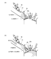
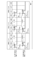
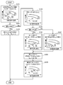
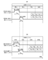
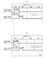
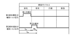
- FIG. 1 is a system configuration diagram of an internal combustion engine according to an embodiment of the present invention. It is a schematic diagram which shows the fuel injection in the intake port of the embodiment, (a) is a primary injection, (b) is a secondary injection. It is a time chart of the injection pulse signal which shows injection timing exchange of the embodiment. It is a flowchart which shows the setting process of the injection pulse signal in the embodiment. It is a time chart of the injection pulse signal which shows the setting of the fuel sharing rate in the embodiment, (a) is a low load low rotation speed side, (b) is a high load high rotation speed side.
- FIG. 1 is a system configuration diagram of an internal combustion engine (four-cycle engine) in the embodiment.
- the downstream side of the intake pipe 12 branches into a first intake port 14 and a second intake port 16, and the downstream ends of the first intake port 14 and the second intake port 16 are independently connected to the cylinder 18. Open.
- the intake pipe 12 and the first intake port 14 form a first intake passage
- the intake pipe 12 and the second intake port 16 form a second intake passage.
- An intake valve 20 is interposed in the portion where the first intake port 14 and the second intake port 16 open to the cylinder 18, and opens and closes the open portions of the intake ports 14 and 16.
- first exhaust ports 22 and second exhaust ports 24 open to the cylinder 18, and the first exhaust port 22 and the second exhaust port 24 join downstream to form an exhaust pipe (not shown). ). Opening portions of the first exhaust port 22 and the second exhaust port 24 are opened and closed by an exhaust valve 26.
- a first fuel injection valve 28 is disposed on the first intake port 14 side (or the first intake port 14) of the intake pipe 12, and on the second intake port 16 side (or the second intake port 16) of the intake pipe 12.
- the second fuel injection valve 30 is disposed, and the first fuel injection valve 28 and the second fuel injection valve 30 are umbrellas of the intake valves 20 interposed with respect to the first intake port 14 and the second intake port 16, respectively. Fuel is injected toward the portion 20a.
- the first fuel injection valve 28 and the second fuel injection valve 30 are electromagnetic fuel injection valves that are opened by lifting the valve body by the magnetic attractive force of the electromagnetic coil. In this manner, since the shared injection amount of one fuel injection valve can be reduced by using the two fuel injection valves 28 and 30, an injection valve excellent in atomization with small injection holes can be used.
- the fuel (gasoline) in the fuel tank 32 is pumped by the fuel pump 34 to the first fuel injection valve 28 and the second fuel injection valve 30, and the fuel supply pressure is discharged from the fuel pump 34.
- the target pressure is controlled by controlling the amount.
- the fuel injected from the first fuel injection valve 28 and the second fuel injection valve 30 is sucked into the combustion chamber 36 through the intake valve 20.
- the fuel sucked into the combustion chamber 36 is ignited and burned by spark ignition of the spark plug 38, and the combustion exhaust is discharged from the first exhaust port 22 and the second exhaust port 24 through the exhaust valve 26.
- An engine control unit (hereinafter referred to as “ECU”) 40 has a built-in microcomputer and inputs output signals from various sensors for detecting the operating conditions of the internal combustion engine 10 to control the fuel pump 34 and the spark plug 38.
- the fuel injection control device that controls the fuel injection by the first fuel injection valve 28 and the second fuel injection valve 30 is configured.
- the ECU 40 is a processing device such as a CPU (Central Processing Unit) or a microprocessor, a volatile memory such as a ROM (Read Only Memory), a nonvolatile memory such as a RAM (Random Access Memory), an A / D (A / D). It includes an input / output interface with analog / digital converter.
- the various sensors include a crank angle sensor 42 that outputs a rotation pulse signal POS synchronized with the rotation of the crankshaft of the internal combustion engine 10, an airflow sensor 44 that outputs a flow rate detection signal Q indicating the intake air amount of the internal combustion engine 10, and an internal combustion engine.
- a water temperature sensor 46 for outputting a temperature detection signal TW indicating ten cooling water temperatures is provided.
- the first fuel injection valve 28 and the second fuel injection valve 30 open at an injection timing and an injection period defined by an injection pulse signal (instruction signal) output from the ECU 40, and inject an amount of fuel proportional to the injection period. To do.
- an injection pulse signal instruction signal
- the ECU 40 injects fuel in each combustion cycle when the first fuel injection valve 28 injects fuel (including an injection start time and an injection end time; the same applies hereinafter) and the second fuel injection valve 30 injects fuel.
- the injection pulse signal is set so as to provide a phase difference between two injection timings with respect to the injection timing.
- an injection with an earlier injection start timing is referred to as a primary injection
- an injection with an later injection start timing is referred to as a secondary injection.
- the ECU 40 starts the fuel injection in the exhaust stroke by one fuel injection valve (for example, the first fuel injection valve 28) in order to promote the vaporization of the injected fuel, and the injection in the exhaust stroke.
- the injection pulse signal of one fuel control valve is set so that the period is longer than the injection period during the intake stroke or so that fuel is injected only during the exhaust stroke.
- the ECU 40 promotes the mixing of air and fuel for the purpose of reducing unburned hydrocarbons and improving fuel efficiency by increasing the combustion speed.
- the fuel injection valve 30 starts injection after one fuel injection valve so that the injection period of the other fuel injection valve during the intake stroke is longer than the injection period of one fuel injection valve during the intake stroke.
- the injection pulse signal of the other fuel control valve is set. For example, in the secondary injection, fuel is injected in synchronization with the air intake period in the intake stroke.
- the ECU 40 sets the injection pulse signal in this way, as shown in FIG. 2A, in the first intake port 14 where the primary injection is performed, the fuel injected by the first fuel injection valve 28 in the exhaust stroke is shown. A part of the fuel adheres to the umbrella portion 20a of the intake valve 20 without being vaporized. However, by absorbing the residual heat of combustion in the immediately preceding expansion stroke, vaporization of the attached fuel is promoted. Further, in the exhaust stroke, the residual heat of combustion is larger than that in the intake stroke, and since the intake flow is not generated, the temperature of the inner wall of the first intake port 14 is not easily lowered. Fuel is also easier to vaporize than the intake stroke.
- the amount of fuel adhering to each intake port 14, 16 in one combustion cycle is such that the injection period in the intake stroke is the same if the fuel injection amounts of the first fuel injection valve 28 and the second fuel injection valve 30 are the same.
- the second fuel injection valve 30 for performing the secondary injection having a relatively long injection period in the intake stroke is disposed rather than the first intake port 14 in which the first fuel injection valve 28 for performing the relatively short primary injection is disposed.
- the second intake port 16 is larger.
- the second fuel injection valve 30 When the first fuel injection valve 28 is fixed as a fuel injection valve that performs primary injection and the second fuel injection valve 30 is fixed as a fuel injection valve that performs secondary injection, the second fuel injection valve 30 In the curved portion 16a of the second intake port 16 in which is disposed, new adhering fuel is generated one after another in each combustion cycle, and the equilibrium adhering amount increases. If the equilibrium adhesion amount increases, the air-fuel ratio fluctuation during transient operation increases, which may adversely affect exhaust emission and fuel efficiency.
- the injection timing (start timing t 1s and end timing t 1e ) at which the first fuel injection valve 28 injects fuel in each combustion cycle and the second fuel injection valve 30 are the fuel.
- the internal combustion engine is provided with a phase difference (t 2s -t 1s ⁇ 0 and t 2e -t 1e ⁇ 0) between two injection timings of the injection timing (start timing t 2s and end timing t 2e )
- the injection pulse signal is set so that the two injection timings are alternately switched every predetermined number of combustion cycles (for example, every cycle) according to the ten operating states.
- the ECU 40 causes the first fuel injection valve 28 and the second fuel injection valve 30 to perform injections in different injection modes (primary injection or secondary injection) in each combustion cycle, thereby operating the internal combustion engine 10.
- the injection pulse signal is set so that the injection mode of the first fuel injection valve 28 and the injection mode of the second fuel injection valve 30 are alternately switched every predetermined number of combustion cycles.
- the primary injection and the secondary injection are alternately switched every predetermined number of combustion cycles.
- the injection mode is changed to the intake mode after a predetermined number of combustion cycles.
- FIG. 4 is a flowchart showing details of the injection pulse signal setting process executed by the processing device of the ECU 40 every combustion cycle.
- the processing device of the ECU 40 reads out a computer program stored in a non-volatile memory such as a ROM and executes it, thereby causing injection pulse signals (instruction signals) to the first fuel injection valve 28 and the second fuel injection valve 30. ) Is set.
- step S101 (abbreviated as “S101” in the figure, the same applies hereinafter), based on the operating state of the internal combustion engine 10, the first fuel injection valve 28 and the second fuel injection valve 30 in each combustion cycle (that is, the first fuel injection valve 30).
- the total fuel injection amount (for the next injection and the second injection) is calculated.
- the pulse width (injection pulse width TI) of the injection pulse signal is calculated as an injection period proportional to the total fuel injection amount.
- the injection pulse width TI is calculated based on the basic injection pulse width (basic fuel injection amount) TP, and the basic injection pulse width TP is calculated from the rotational speed (the rotational speed of the internal combustion engine 10 calculated from the rotation pulse signal POS of the crank angle sensor 42).
- the engine speed is calculated based on the intake air amount detected from the flow rate detection signal Q of the air flow sensor 44.
- the basic injection pulse width TP is set by referring to a basic injection pulse width map in which the basic injection pulse width TP is associated with the engine speed and the intake air amount.
- the basic injection pulse width map is obtained in advance by experiments and simulations and is stored in a nonvolatile memory such as a ROM.
- the operating state of the internal combustion engine 10 is, for example, in a region A that is a low load / low rotational speed region, a medium load / medium rotational speed region by a combination of the engine rotational speed and the intake air amount.
- a region B is divided into regions C is a high-load, high rotational speed region, the combination of the engine speed and the intake air amount, if applicable to the region a, set the basic injection pulse width TP to TP a, region if applicable to B sets the basic injection pulse width TP to TP B, if applicable to the region C has set the basic injection pulse width TP to TP C.
- Basic injection pulse width TP A, TP B, TP C has a magnitude relation between TP A ⁇ TP B ⁇ TP C .
- the ECU 40 calculates various correction coefficients COEF based on the coolant temperature detected based on the temperature detection signal TW output from the water temperature sensor 46, and calculates the basic injection pulse width TP, the various correction coefficients COEF, The total fuel injection amount to be injected into each cylinder 18 per combustion cycle as corrected by the correction value Ts for compensating for the operation delay of the first fuel injection valve 28 and the second fuel injection valve 30 as shown in the following equation.
- the injection pulse width TI A set in the region A, the injection pulse width TI B set in the region B , and the injection pulse width TI C set in the region C are expressed by the following equations, respectively. It has a magnitude relationship of A ⁇ TI B ⁇ TI C.
- step S102 it is determined whether or not the operating state of the internal combustion engine 10 when the fuel injection amount is calculated in step S101 corresponds to the region C.
- the basic pulse width TP is TP A set in step S101, TP B, may be determined by whether either TP C. If it is determined that the operating state of the internal combustion engine 10 corresponds to the region C, the process proceeds to step S103 (Yes). On the other hand, when it is determined that the operation state of the internal combustion engine 10 does not correspond to the region C, that is, corresponds to the region A or C, the process proceeds to step S104 (No).
- the sum (TI 1 + TI 2 ) of the injection pulse width TI 1 of the primary injection and the injection pulse width TI 2 of the secondary injection becomes the injection pulse width TI C set in the region C.
- the reason why the fuel sharing ratio P is set to 1 in the region C is that in the region C, the required fuel injection amount increases according to the operating state of the internal combustion engine 10 and the injection period in the primary injection and the secondary injection This is because it is necessary to maximize the value. Accordingly, the injection pulse widths TI 1 and TI 2 become longer as it becomes difficult to change the injection timing, such as the period from the beginning of the exhaust stroke to the middle of the intake stroke, and therefore the injection timing of the first fuel injection valve 28. And the injection timing of the second fuel injection valve 30 are synchronized without providing a phase difference, and the replacement of the injection timing is stopped. Thereby, the setting process of the injection pulse signal for the first fuel injection valve 28 and the second fuel injection valve 30 when the operating state of the internal combustion engine 10 corresponds to the region C is completed.
- step S104 the fuel sharing rate P when the operating state of the internal combustion engine 10 corresponds to the region A or the region B is set, thereby calculating the injection pulse widths in the primary injection and the secondary injection.
- the fuel sharing ratio P is set so as to change according to the operating state of the internal combustion engine 10, that is, depending on how much the intake air amount and the engine rotational speed are in the region A and the region B.
- the fuel sharing rate P is set, for example, by referring to a fuel sharing rate map in which the fuel sharing rate P is associated with the engine speed and the intake air amount.
- the fuel injection ratio P is, than the injection pulse width TI 2 of the secondary injection as towards the injection pulse width TI 1 of the primary injection increases (TI 1> TI 2), each combustion In the cycle, it is set to be larger than 1 in order to reduce the amount of injected fuel adhering to the inner wall of the intake port.
- the fuel sharing ratio P is set so as to decrease as the intake air amount or the engine speed increases in the regions A and B, and the fuel injection amount injected in the secondary injection in each combustion cycle.
- the fuel injection amount injected in the primary injection By approaching the fuel injection amount injected in the primary injection, the mixture of fuel and air sucked into the combustion chamber 36 from the first intake port 14, and into the combustion chamber 36 from the second intake port 16. The deviation of the fuel concentration in the two air-fuel mixtures of the sucked fuel and air is reduced.
- TI A computed as the injection pulse width TI at step S101
- TI A1 the injection pulse width TI 1 of the primary injection
- TI A2 the injection pulse width TI 2 of the secondary injection
- the fuel injection ratio P instead of changing from P A to P B, the fuel injection ratio P which is calculated by setting the P A first A predetermined amount may be directly added to the injection pulse width TI A1 of the next injection and the injection pulse width TI A2 of the second injection.
- the injection pulse width TI 1 of the primary injection increases from TI A1 to TI X1
- the injection pulse width TI 2 of the secondary injection changes from TI A2 to TI X2 .
- step S105 it is determined whether or not the operating state of the internal combustion engine 10 corresponds to the region B when the fuel injection amount is calculated in step S101. If it is determined that the operating state of the internal combustion engine 10 corresponds to the region B, the process proceeds to step S106 (Yes). On the other hand, when it is determined that the operation state of the internal combustion engine 10 does not correspond to the region B, that is, corresponds to the region A, the process proceeds to step S107 (No).
- step S106 the injection end timing t 1eB of the primary injection when the operating state of the internal combustion engine 10 corresponds to the region B is set.
- the injection end timing t 1eB in the primary injection is set according to the operating state of the internal combustion engine 10, that is, according to the intake air amount and the engine speed in the region B. Specifically, in region B, the injection end timing t 1eB is set later as the intake air amount or the engine speed increases.
- the region B which is a medium load / medium rotational speed region
- a period overlapping with the air intake period in the intake stroke of the injection period of the primary injection increases as the intake air amount or the engine rotational speed increases. By increasing the length, mixing of air and fuel is promoted.
- the injection end timing t 1eB of the primary injection when the intake air amount or the engine speed is relatively low (that is, on the region A side) is t
- the value of 1e ⁇ is set, as shown in FIG. 6B, in the region B, the injection of the primary injection when the intake air amount or the engine rotational speed is relatively high (that is, on the region C side).
- set the end time t 1Eb a value greater t 1Ibeta than the value of t 1e ⁇
- the injection end timing t 1Eb in the region B may be set in two in accordance with the operating state of the internal combustion engine 10.
- step S107 the injection start timing t 1sA of the primary injection when the operating state of the internal combustion engine 10 corresponds to the region A is set.
- the injection start timing t 1sA of the primary injection is set according to the operating state of the internal combustion engine 10, that is, according to the intake air amount and the engine speed in the region A. Specifically, in region A, the injection start timing t 1sA of the primary injection is set earlier as the intake air amount or the engine speed increases.
- the region A that is the low load / low rotational speed region As the intake air amount or the engine rotational speed increases, the period in the exhaust stroke of the injection period of the primary injection is increased, or the first By performing the next injection during the exhaust stroke, the injected fuel is easily vaporized, and the amount of the injected fuel attached to the inner wall of the intake port is reduced.
- the injection start timing t 1sA of the primary injection when the intake air amount or the engine speed is relatively low is set to the value of t 1s ⁇ .
- the injection start timing t 1sA of the primary injection when the intake air amount or the engine speed is relatively high is the value of t 1s ⁇ . set to a value smaller t 1Esubeta than may be the primary injection, the injection start timing t 1SA in the region a so as to set two types according to the operating state of the internal combustion engine 10.
- step S108 the injection end timing t2e of the secondary injection when the operating state of the internal combustion engine 10 corresponds to the region A or the region B is set.
- the injection end timing t 2e of the secondary injection is fixed at a fixed time during the intake stroke regardless of the region A or the region B in order to reduce the amount of fuel injected on the inner wall of the port due to the intake air flow in each combustion cycle. Is done.
- the injection end timing t 2e of the secondary injection may be set to a timing at which the lift amount of the intake valve 20 is maximized, that is, the degree of opening of the intake valve 20 is maximized.
- step S109 it is determined whether or not the current injection mode of the first fuel injection valve 28 and the second fuel injection valve 30 is continuous up to a predetermined combustion cycle number N.
- the current injection timings of the first fuel injection valve 28 and the second fuel injection valve 30 are interchanged. That is, when the injection mode of the first fuel injection valve 28 is set to the primary injection and the injection mode of the second fuel injection valve 30 is set to the secondary injection, the injection by the injection mode is performed in a predetermined combustion cycle.
- the injection mode of the first fuel injection valve 28 is switched to the secondary injection, and the injection mode of the second fuel injection valve 30 is switched to the primary injection.
- the injection in the injection mode is a predetermined combustion.
- the injection mode of the first fuel injection valve 28 is switched to the primary injection, and the injection mode of the second fuel injection valve 30 is switched to the secondary injection.
- the predetermined combustion cycle number N is set so as to change according to the operating state of the internal combustion engine 10. Specifically, the predetermined number of combustion cycles N (an integer greater than or equal to 1) is set so as to decrease as the intake air amount or the engine speed increases in the regions A and B. In areas A and B, as the intake air amount or the engine speed increases, the fuel injection amounts of the first fuel injection valve 28 and the second fuel injection valve 30 increase. The amount of fuel injected on the inner wall increases. In contrast, the primary injection and the secondary injection are frequently switched by reducing the number of consecutive combustion cycles in the same state of the injection modes performed in the first fuel injection valve 28 and the second fuel injection valve 30. In particular, vaporization of the attached fuel generated by the secondary injection is promoted to suppress an increase in the amount of equilibrium adhesion.
- the injection timings of the first fuel injection valve 28 and the second fuel injection valve 30 are switched every combustion cycle, that is, the first fuel injection valve 28 and the second fuel injection. Since the injection modes performed in the valve 30 are not continuous, the amount of equilibrium adhesion is minimized.
- the predetermined combustion cycle number N when the intake air amount or the engine speed is relatively low in the regions A and B, the predetermined combustion cycle number N is set to N L (eg, 3), As shown in FIG. 9C, when the intake air amount or the engine speed is relatively high in the regions A and B, the predetermined combustion cycle number N is set to N H (for example, 1). As shown in (b), when the intake air amount or the engine speed is medium in the regions A and B, the predetermined number of combustion cycles N is set to N M (for example, 2), and N L , The magnitude relationship between N M and N H can satisfy N L ⁇ N M ⁇ N H.
- Steps S104 to S109 the setting of the injection pulse signal for the first fuel injection valve 28 and the second fuel injection valve 30 when the operating state of the internal combustion engine 10 corresponds to the region A or the region B is completed.
- a phase difference is provided between two injection timings, that is, an injection timing at which the first fuel injection valve 28 injects fuel and an injection timing at which the second fuel injection valve 30 injects fuel in each combustion cycle.
- the injection pulse signal is set so that the two injection timings are alternately switched every predetermined number of combustion cycles N according to the operating state of the internal combustion engine 10. Therefore, in each combustion cycle, even if the fuel is injected by the secondary injection having a relatively long injection period in the intake stroke, even if a part of the injected fuel adheres to the port inner wall of one intake port by the intake air flow, it is predetermined.
- the injection mode can be switched to primary injection with a relatively short injection period in the intake stroke to promote vaporization of the attached fuel. For this reason, it is possible to suppress the increase in the amount of equilibrium adhesion because the injected fuel adheres one after another at the attachment site of one intake port in each combustion cycle while taking into account the promotion of mixing of air and fuel. It is possible to improve the exhaust emission and fuel consumption performance by suppressing the air-fuel ratio fluctuation.
- one fuel injection valve starts fuel injection in the exhaust stroke.
- the valve may start injection before the other fuel injection valve.
- one fuel injection valve may inject fuel during a period in which the opening degree of the intake valve 20 is relatively small during the intake stroke.
- the degree of opening of the intake valve 20 is set so that the intake air amount in the injection period of the other fuel injection valve is larger than the intake air amount in the injection period of one fuel injection valve.
- the other fuel injection valve may inject fuel during a period in which is relatively large.
- the parameter that defines the operating state of the internal combustion engine 10 is not limited to the combination of the engine rotational speed and the intake air amount described above.
- the generated torque of the internal combustion engine 10 and the intake pipe 12 Parameters indicating the load (engine load) of the internal combustion engine 10 such as negative pressure and throttle opening can be combined.
- the region A and the operation state of the internal combustion engine 10 by dividing the regions B and C, and the basic injection pulse width TP corresponding to the respective regions TP A, TP B, the three TP C
- the operating state of the internal combustion engine 10 may be divided into two or four or more regions, and the basic injection pulse width TP corresponding to each region may be set.
- the end timing t 1eB the region A is divided into a case where the intake air amount or the engine rotational speed is relatively low and a case where the region is relatively high
- the injection start timing t 1sB of the primary injection is set.
- the flowchart in FIG. 4 shows an example of the setting process of the injection pulse signal.
- the region A to the region C are determined, and the setting process of the injection pulse width signal is executed according to the determined region. May be.
- the injection pulse width TI A calculated as in step S101 in the first step, to set the fuel injection ratio P A, as in step S104 in the second step
- the injection pulse width TI A1 of the primary injection and the injection pulse width TI A2 of the secondary injection are calculated, and the injection start timing t 1sA of the primary injection is set as in step S107 in the third step.
- the injection end timing t 1eA of the primary injection is calculated
- the injection end timing t 2e of the secondary injection is set as in step S108 in the fourth step
- the injection start timing t of the secondary injection is set. 2s may be calculated, and the injection timing may be changed in the fifth step as in step S109.
- step S101, step S104, step S106, step S108, and step S109 are performed in this order.
- step S101 You may perform each process of step S103 in this order.
Landscapes
- Engineering & Computer Science (AREA)
- Chemical & Material Sciences (AREA)
- Combustion & Propulsion (AREA)
- Mechanical Engineering (AREA)
- General Engineering & Computer Science (AREA)
- Electrical Control Of Air Or Fuel Supplied To Internal-Combustion Engine (AREA)
Abstract
気筒毎に第1吸気通路と第2吸気通路とを備え、第1吸気通路に第1燃料噴射弁を配置し、第2吸気通路に第2燃料噴射弁を配置した内燃機関に対して、第1燃料噴射弁及び第2燃料噴射弁に燃料の噴射を行わせる燃料噴射制御装置が、各燃焼サイクルにおいて第1燃料噴射弁が燃料を噴射する噴射時期と第2燃料噴射弁が燃料を噴射する噴射時期との2つの噴射時期に位相差を設けつつ、2つの噴射時期を所定燃焼サイクル数毎に交互に入れ替えるように、第1燃料噴射弁及び第2燃料噴射弁に対する噴射パルス信号を設定する。
Description
本発明は、気筒毎に第1吸気通路と第2吸気通路とを備え、第1吸気通路に第1燃料噴射弁を配置し、第2吸気通路に第2燃料噴射弁を配置した内燃機関に対して、第1燃料噴射弁及び第2燃料噴射弁から燃料の噴射を行わせる燃料噴射制御装置に関する。
気筒毎に第1吸気通路と第2吸気通路とを備え、第1吸気通路に第1燃料噴射弁を配置し、第2吸気通路に第2燃料噴射弁を配置した内燃機関に対し、第1燃料噴射弁及び第2燃料噴射弁から燃料の噴射を行わせる燃料噴射制御装置として、第1燃料噴射弁が噴射する噴射時期と第2燃料噴射弁が噴射する噴射時期との2つの噴射時期に位相差を設けたものが知られている(例えば、特許文献1参照)。
ところで、例えば、第1燃料噴射弁の噴射時期及び第2燃料噴射弁の噴射時期のうち一方を吸気行程に同期させて空気と燃料の混合を促進する等、第1燃料噴射弁の噴射時期と第2燃料噴射弁の噴射時期とで、各吸気通路における吸入空気量が異なる場合が考えられる。吸入空気量が増えると、吸気通路の湾曲部において、吸気流の慣性により噴射燃料が気化せずに吸気通路内壁に付着する付着量が多くなる。
したがって、第1燃料噴射弁の噴射時期と第2燃料噴射弁の噴射時期とを位相差を設けたまま固定してしまうと、噴射時期の吸入空気量が多い一方の吸気通路において、燃焼サイクル毎に新たな付着燃料が発生して、吸気通路内壁における平衡付着量が増加するため、過渡運転時の空燃比変動が大きくなり、排気エミッションや燃費性能に好ましくない影響を与えるおそれがある。
本発明は上記問題点に鑑みてなされたものであり、第1吸気通路に配置された第1燃料噴射弁の噴射時期と第2吸気通路に配置された第2燃料噴射弁の噴射時期とに位相差を設けた場合に、第1吸気通路と第2通気通路との間における平衡付着量の偏りを抑制する燃料噴射制御装置を提供することを目的とする。
このため、本発明に係る燃料噴射制御装置は、気筒毎に第1吸気通路と第2吸気通路とを備え、第1吸気通路に第1燃料噴射弁を配置し、第2吸気通路に第2燃料噴射弁を配置した内燃機関に対して、第1燃料噴射弁及び第2燃料噴射弁に燃料の噴射を行わせるものであって、各燃焼サイクルにおいて第1燃料噴射弁が燃料を噴射する噴射時期と第2燃料噴射弁が燃料を噴射する噴射時期との2つの噴射時期に位相差を設けつつ、2つの噴射時期を所定燃焼サイクル数毎に交互に入れ替えている。
本発明の燃料噴射制御装置によれば、第1吸気通路に配置された第1燃料噴射弁の噴射時期と第2吸気通路に配置された第2燃料噴射弁の噴射時期とに位相差が設けられていても、第1吸気通路と第2通気通路との間における平衡付着量の偏りを抑制することができる。
以下、添付された図面を参照し、本発明を実施するための実施形態について詳述する。
図1は、実施形態における内燃機関(4サイクルエンジン)のシステム構成図である。
図1は、実施形態における内燃機関(4サイクルエンジン)のシステム構成図である。
内燃機関10において、吸気管12の下流側は、第1吸気ポート14及び第2吸気ポート16に分岐し、第1吸気ポート14及び第2吸気ポート16の下流端はそれぞれ独立して気筒18に開口する。吸気管12及び第1吸気ポート14が第1吸気通路を形成し、吸気管12及び第2吸気ポート16が第2吸気通路を形成する。
第1吸気ポート14及び第2吸気ポート16が気筒18に開口する部分には、それぞれ、吸気バルブ20が介装され、各吸気ポート14,16の開口部分を開閉する。
第1吸気ポート14及び第2吸気ポート16が気筒18に開口する部分には、それぞれ、吸気バルブ20が介装され、各吸気ポート14,16の開口部分を開閉する。
一方、2つの独立した第1排気ポート22及び第2排気ポート24の上流端が気筒18に開口し、第1排気ポート22及び第2排気ポート24は下流側で合流して排気管(図示省略)に接続する。第1排気ポート22及び第2排気ポート24の開口部分は、排気バルブ26によって開閉される。
吸気管12の第1吸気ポート14側(あるいは第1吸気ポート14)には第1燃料噴射弁28を配置し、吸気管12の第2吸気ポート16側(あるいは第2吸気ポート16)には第2燃料噴射弁30を配置してあり、第1燃料噴射弁28及び第2燃料噴射弁30は、第1吸気ポート14及び第2吸気ポート16についてそれぞれ介装された各吸気バルブ20の傘部20aに向けて燃料を噴射する。
第1燃料噴射弁28及び第2燃料噴射弁30は、電磁コイルの磁気吸引力によって弁体をリフトさせることで開弁する電磁式燃料噴射弁である。このように、2つの燃料噴射弁28,30を用いることで1個の燃料噴射弁の分担噴射量を低減できるので、噴孔の小さな微粒化に優れた噴射弁を用いることができる。
第1燃料噴射弁28及び第2燃料噴射弁30には、燃料タンク32内の燃料(ガソリン)が燃料ポンプ34によって圧送されるようになっており、燃料の供給圧は、燃料ポンプ34の吐出量の制御によって目標圧に制御される。
第1燃料噴射弁28及び第2燃料噴射弁30から噴射された燃料は、吸気バルブ20を介して燃焼室36に吸引される。燃焼室36に吸引された燃料は、点火プラグ38の火花点火によって着火燃焼し、燃焼排気は、排気バルブ26を介して、第1排気ポート22及び第2排気ポート24から排出される。
エンジン・コントロール・ユニット(以下、「ECU」という)40は、マイクロコンピュータを内蔵し、内燃機関10の運転条件を検出する各種センサの出力信号を入力して、燃料ポンプ34及び点火プラグ38を制御する制御装置を構成する他、第1燃料噴射弁28及び第2燃料噴射弁30による燃料の噴射を制御する燃料噴射制御装置を構成する。ECU40は、具体的には、CPU(Central Processing Unit)やマイクロプロセッサ等の処理装置、ROM(Read Only Memory)等の揮発性メモリ、RAM(Random Access Memory)等の不揮発性メモリ、A/D(Analog/Digital)変換器等を備えた入出力インタフェースを含んでいる。
各種センサとしては、内燃機関10のクランクシャフトの回転に同期する回転パルス信号POSを出力するクランク角センサ42、内燃機関10の吸入空気量を示す流量検出信号Qを出力するエアフローセンサ44、内燃機関10の冷却水温度を示す温度検出信号TWを出力する水温センサ46などを設けてある。
第1燃料噴射弁28及び第2燃料噴射弁30は、ECU40が出力する噴射パルス信号(指示信号)によって規定される噴射時期及び噴射期間で開弁し、噴射期間に比例する量の燃料を噴射する。
ここで、ECU40は、各燃焼サイクルにおいて第1燃料噴射弁28が燃料を噴射する噴射時期(噴射開始時期及び噴射終了時期を含む。以下、同様)と第2燃料噴射弁30が燃料を噴射する噴射時期との2つの噴射時期に位相差を設けるように、噴射パルス信号を設定している。各燃焼サイクルにおいて、噴射開始時期が先の噴射を第1次噴射といい、噴射開始時期が後の噴射を第2次噴射というものとする。
ECU40は、第1次噴射において、噴射燃料の気化を促進すべく、一方の燃料噴射弁(例えば、第1燃料噴射弁28)が、排気行程において燃料の噴射を開始し、排気行程中における噴射期間が吸気行程中における噴射期間よりも長くなるように、あるいは、排気行程中でのみ燃料を噴射するように、一方の燃料制御弁の噴射パルス信号を設定する。
また、ECU40は、第2次噴射において、未燃炭化水素の低減、及び燃焼の高速化による燃費向上を目的として空気と燃料との混合を促進すべく、他方の燃料噴射弁(例えば、第2燃料噴射弁30)が一方の燃料噴射弁よりも後に噴射を開始して、吸気行程中における他方の燃料噴射弁の噴射期間が、吸気行程中における一方の燃料噴射弁の噴射期間より長くなるように、他方の燃料制御弁の噴射パルス信号を設定する。例えば、第2次噴射では、吸気行程における空気の吸入期間と同期して燃料を噴射する。
このようにECU40が噴射パルス信号を設定すると、図2(a)に示すように、第1次噴射が行われる第1吸気ポート14において、第1燃料噴射弁28が排気行程で噴射した燃料の一部は、気化せずに吸気バルブ20の傘部20aに付着するが、直前の膨張行程における燃焼の残留熱を吸熱することで、付着燃料の気化が促進される。
また、排気行程では、燃焼の残留熱が吸気行程に比べて大きく、かつ、吸気流が発生しない分、第1吸気ポート14のポート内壁の温度も低下しにくいため、ポート内壁に液着した付着燃料も、吸気行程に比べて気化しやすい。
また、排気行程では、燃焼の残留熱が吸気行程に比べて大きく、かつ、吸気流が発生しない分、第1吸気ポート14のポート内壁の温度も低下しにくいため、ポート内壁に液着した付着燃料も、吸気行程に比べて気化しやすい。
一方、図2(b)に示すように、第2次噴射が行われる第2吸気ポート16において、第2燃料噴射弁30が吸気行程で噴射した燃料の一部は、気化しないまま、吸気流の慣性により第2吸気ポート16の湾曲部16aにおけるポート内壁に付着しやすくなるが、かかるポート内壁は吸気流により冷却され、また、燃焼の残留熱も排気行程に比べると小さくなるため、付着燃料は排気行程に比べて気化しにくい。
したがって、1燃焼サイクルにおける各吸気ポート14,16への燃料の付着量は、第1燃料噴射弁28及び第2燃料噴射弁30の各燃料噴射量が同じであれば、吸気行程における噴射期間が比較的短い第1次噴射を行う第1燃料噴射弁28を配置した第1吸気ポート14よりも、吸気行程における噴射期間が比較的長い第2次噴射を行う第2燃料噴射弁30を配置した第2吸気ポート16の方が大きくなる。
そして、第1燃料噴射弁28が第1次噴射を行う燃料噴射弁として固定され、第2燃料噴射弁30が第2次噴射を行う燃料噴射弁として固定されると、第2燃料噴射弁30を配置した第2吸気ポート16の湾曲部16aには燃焼サイクル毎に次々と新たな付着燃料が発生して、平衡付着量が増大してしまう。平衡付着量が増大すると、過渡運転時の空燃比変動が大きくなり、排気エミッションや燃費性能に好ましくない影響を与えるおそれがある。
そして、第1燃料噴射弁28が第1次噴射を行う燃料噴射弁として固定され、第2燃料噴射弁30が第2次噴射を行う燃料噴射弁として固定されると、第2燃料噴射弁30を配置した第2吸気ポート16の湾曲部16aには燃焼サイクル毎に次々と新たな付着燃料が発生して、平衡付着量が増大してしまう。平衡付着量が増大すると、過渡運転時の空燃比変動が大きくなり、排気エミッションや燃費性能に好ましくない影響を与えるおそれがある。
このため、図3に示すように、ECU40では、各燃焼サイクルにおいて第1燃料噴射弁28が燃料を噴射する噴射時期(開始時期t1s及び終了時期t1e)と第2燃料噴射弁30が燃料を噴射する噴射時期(開始時期t2s及び終了時期t2e)との2つの噴射時期に位相差(t2s-t1s≠0、及び、t2e-t1e≠0)を設けつつ、内燃機関10の運転状態に応じて、2つの噴射時期を所定燃焼サイクル数毎(例えば、1サイクル毎)に交互に入れ替えるように、噴射パルス信号を設定している。換言すれば、ECU40は、各燃焼サイクルにおいて第1燃料噴射弁28及び第2燃料噴射弁30に異なる噴射モード(第1次噴射又は第2次噴射)で噴射を行わせ、内燃機関10の運転状態に応じて、第1燃料噴射弁28の噴射モードと第2燃料噴射弁30の噴射モードとを所定燃焼サイクル数毎に交互に入れ替えるように、噴射パルス信号を設定している。
このように、第1燃料噴射弁28及び第2燃料噴射弁30では、所定燃焼サイクル数毎に第1次噴射と第2次噴射とが交互に入れ替えられる。これにより、吸気行程における噴射期間が比較的長い第2次噴射により噴射燃料の一部が吸気流によって吸気ポートのポート内壁に付着しても、所定燃焼サイクル数経過後には、噴射モードを、吸気行程における噴射期間が比較的短い第1次噴射に入れ替えて、付着燃料の気化を促進するようにしている。このため、空気と燃料との混合促進を考慮しつつ、燃焼サイクル毎に、一方の吸気ポートの付着部位に噴射燃料が次々と付着して平衡付着量が増大することを抑制することができる。
図4は、ECU40の処理装置により燃焼サイクル1回毎に実行される噴射パルス信号の設定処理の詳細を示すフローチャートである。
なお、ECU40の処理装置が、ROM等の不揮発性メモリに格納されたコンピュータプログラムを読み出してこれを実行することにより、第1燃料噴射弁28及び第2燃料噴射弁30に対する噴射パルス信号(指示信号)を設定する指示信号設定手段が実現される。
なお、ECU40の処理装置が、ROM等の不揮発性メモリに格納されたコンピュータプログラムを読み出してこれを実行することにより、第1燃料噴射弁28及び第2燃料噴射弁30に対する噴射パルス信号(指示信号)を設定する指示信号設定手段が実現される。
ステップS101(図中において「S101」と略記する。以下同様)では、内燃機関10の運転状態に基づいて、各燃焼サイクルにおける第1燃料噴射弁28及び第2燃料噴射弁30の(すなわち第1次噴射及び第2次噴射の)合計燃料噴射量を演算する。詳細には、合計燃料噴射量に比例する噴射期間として、噴射パルス信号のパルス幅(噴射パルス幅TI)を演算する。
噴射パルス幅TIは、基本噴射パルス幅(基本燃料噴射量)TPに基づいて演算され、基本噴射パルス幅TPは、クランク角センサ42の回転パルス信号POSから演算された内燃機関10の回転速度(機関回転速度)と、エアフローセンサ44の流量検出信号Qから検出された吸入空気量と、に基づいて演算される。基本噴射パルス幅TPは、例えば、機関回転速度及び吸入空気量に対して基本噴射パルス幅TPを関連付けた基本噴射パルス幅マップを参照することで設定される。基本噴射パルス幅マップは、実験やシミュレーションにより予め求められ、ROM等の不揮発性メモリに記憶されている。
本実施形態では、説明の便宜上、内燃機関10の運転状態を、例えば、機関回転速度及び吸入空気量の組み合せにより、低負荷・低回転速度領域である領域A、中負荷・中回転速度領域である領域B、高負荷・高回転速度領域である領域Cに区分し、機関回転速度及び吸入空気量の組み合せが、領域Aに該当する場合は基本噴射パルス幅TPをTPAに設定し、領域Bに該当する場合は基本噴射パルス幅TPをTPBに設定し、領域Cに該当する場合は基本噴射パルス幅TPをTPCに設定している。基本噴射パルス幅TPA,TPB,TPCは、TPA<TPB<TPCの大小関係を有している。
更に、ECU40は、水温センサ46から出力された温度検出信号TWに基づいて検出した冷却水温度などに基づいて、各種補正係数COEFを演算し、基本噴射パルス幅TPを、各種補正係数COEFや、第1燃料噴射弁28及び第2燃料噴射弁30の作動遅れを補償する補正値Tsで補正して、下式に示すように、1燃焼サイクル当たりに各気筒18内に噴射する合計燃料噴射量に相当する噴射パルス幅TIを算出する。
TI=TP×COEF+Ts
TI=TP×COEF+Ts
したがって、領域Aで設定される噴射パルス幅TIA、領域Bで設定される噴射パルス幅TIB、及び領域Cで設定される噴射パルス幅TICは、それぞれ下式のように示され、TIA<TIB<TICの大小関係を有する。
TIA=TPA×COEF+Ts
TIB=TPB×COEF+Ts
TIC=TPC×COEF+Ts
TIA=TPA×COEF+Ts
TIB=TPB×COEF+Ts
TIC=TPC×COEF+Ts
ステップS102では、ステップS101で燃料噴射量を演算したときの内燃機関10の運転状態が領域Cに該当するか否かを判定する。例えば、ステップS101で設定された基本パルス幅TPがTPA、TPB、TPCのいずれかであるかによって判定してもよい。
内燃機関10の運転状態が領域Cに該当すると判定された場合には、ステップS103へ進む(Yes)。一方、内燃機関10の運転状態が領域Cに該当しない、すなわち領域A又はCに該当すると判定された場合には、ステップS104へ進む(No)。
内燃機関10の運転状態が領域Cに該当すると判定された場合には、ステップS103へ進む(Yes)。一方、内燃機関10の運転状態が領域Cに該当しない、すなわち領域A又はCに該当すると判定された場合には、ステップS104へ進む(No)。
ステップS103では、第2次噴射の噴射パルス幅TI2に対する第1次噴射の噴射パルス幅TI1の比率である燃料分担率P(=TI1/TI2)を1に設定して、第1次噴射の噴射期間と第2次噴射の噴射期間とを同じにする。第1次噴射の噴射パルス幅TI1と第2次噴射の噴射パルス幅TI2との和(TI1+TI2)は、領域Cで設定される噴射パルス幅TICとなる。
第1次噴射の噴射パルス幅TI1は、下式にP=1を代入し、TI1について解くことでTI1=TIC/2と求めることができ、これにより、第2次噴射の噴射パルス幅TI2は、TI2=TIC/2と求めることができ、TI1=TI2となる。
TIC=TI1+TI2
P=TI1/TI2
TIC=TI1+TI2
P=TI1/TI2
領域Cで燃料分担率Pを1に設定するのは、領域Cでは、内燃機関10の運転状態に応じて必要となる燃料噴射量が増大して第1次噴射及び第2次噴射における噴射期間を最大にする必要があるからである。したがって、噴射パルス幅TI1,TI2は、例えば、排気行程の最初から吸気行程の中間までの期間等、噴射時期の入れ替えが困難となる程長くなるため、第1燃料噴射弁28の噴射時期と第2燃料噴射弁30の噴射時期には位相差を設けずに同期させ、噴射時期の入れ替えは停止する。これにより、内燃機関10の運転状態が領域Cに該当する場合の第1燃料噴射弁28及び第2燃料噴射弁30に対する噴射パルス信号の設定処理が終了する。
ステップS104では、内燃機関10の運転状態が領域A又は領域Bに該当する場合の燃料分担率Pを設定し、これにより第1次噴射及び第2次噴射における各噴射パルス幅を演算する。
燃料分担率Pは、内燃機関10の運転状態に応じて、すなわち、領域A及び領域Bにおいて吸入空気量及び機関回転速度がどの程度であるかによって変化するように設定される。燃料分担率Pは、例えば、機関回転速度及び吸入空気量に対して燃料分担率Pを関連付けた燃料分担率マップを参照することで設定される。
燃料分担率Pは、内燃機関10の運転状態に応じて、すなわち、領域A及び領域Bにおいて吸入空気量及び機関回転速度がどの程度であるかによって変化するように設定される。燃料分担率Pは、例えば、機関回転速度及び吸入空気量に対して燃料分担率Pを関連付けた燃料分担率マップを参照することで設定される。
詳細には、燃料分担率Pは、第2次噴射の噴射パルス幅TI2よりも第1次噴射の噴射パルス幅TI1の方が大きくなるようにして(TI1>TI2)、各燃焼サイクルにおいて、吸気ポートのポート内壁に対する噴射燃料の付着量を低減すべく、1より大きく設定される。
また、燃料分担率Pは、領域A及び領域Bにおいて吸入空気量又は機関回転速度が高くなるに従って小さくなるように設定されて、各燃焼サイクルにおいて、第2次噴射で噴射される燃料噴射量を第1次噴射で噴射される燃料噴射量に近づけることで、第1吸気ポート14から燃焼室36内に吸入された燃料と空気との混合気、及び第2吸気ポート16から燃焼室36内に吸入された燃料と空気との混合気、の2つの混合気における燃料濃度の偏りを低減するようにしている。
以下の説明では、便宜上、領域Aにおける燃料分担率PをPAとし、領域Bにおける燃料分担率PをPBとして、燃料分担率PがPAとPBのいずれかに設定されるものとする(1<PB<PA)。
以下の説明では、便宜上、領域Aにおける燃料分担率PをPAとし、領域Bにおける燃料分担率PをPBとして、燃料分担率PがPAとPBのいずれかに設定されるものとする(1<PB<PA)。
図5(a)に示すように、領域Aの場合には、本ステップで燃料分担率Pが1より大きいPAに設定されることで、ステップS101で噴射パルス幅TIとして演算されたTIAの値により、下式のように、第1次噴射の噴射パルス幅TI1としてのTIA1及び第2次噴射の噴射パルス幅TI2としてのTIA2が演算される。
TI1=TIA1=PA×TIA/(PA+1)
TI2=TIA2=TIA/(PA+1)
TI1=TIA1=PA×TIA/(PA+1)
TI2=TIA2=TIA/(PA+1)
一方、図5(b)に示すように、領域Bの場合には、本ステップで燃料分担率PがPAの値より小さく1より大きいPBの値に設定されることで、ステップS101で噴射パルス幅TIとして演算されたTIBの値により、下式のように、第1次噴射の噴射パルス幅TI1としてのTIB1及び第2次噴射の噴射パルス幅TI2としてのTIB2が演算される。
TI1=TIB1=PB×TIB/(PB+1)
TI2=TIB2=TIB/(PB+1)
TI1=TIB1=PB×TIB/(PB+1)
TI2=TIB2=TIB/(PB+1)
なお、領域Aから領域Bに遷移した場合に、前述のように、燃料分担率PをPAからPBへ変化させる代わりに、燃料分担率PをPAに設定して演算された第1次噴射の噴射パルス幅TIA1及び第2次噴射の噴射パルス幅TIA2に直接所定量を加算してもよい。
例えば、領域Aから領域Bに遷移した場合に、第1次噴射の噴射パルス幅TI1がTIA1からTIX1に増加し、第2次噴射の噴射パルス幅TI2がTIA2からTIX2に増加したとすると、第1次噴射の噴射パルス幅TI1の増加分ΔTI1(=TIX1-TIA1)と第2次噴射の噴射パルス幅TI2の増加分ΔTI2(=TIX2-TIA2)との大小関係がΔTI1<ΔTI2となり、かつ、TIX1とTIX2との和が噴射パルス幅TIBと一致するΔTI1及びΔTI2を演算し、このΔTI1及びΔTI2を、それぞれ第1次噴射の噴射パルス幅TIA1及び第2次噴射の噴射パルス幅TIA2に加算する所定量として設定することができる。
例えば、領域Aから領域Bに遷移した場合に、第1次噴射の噴射パルス幅TI1がTIA1からTIX1に増加し、第2次噴射の噴射パルス幅TI2がTIA2からTIX2に増加したとすると、第1次噴射の噴射パルス幅TI1の増加分ΔTI1(=TIX1-TIA1)と第2次噴射の噴射パルス幅TI2の増加分ΔTI2(=TIX2-TIA2)との大小関係がΔTI1<ΔTI2となり、かつ、TIX1とTIX2との和が噴射パルス幅TIBと一致するΔTI1及びΔTI2を演算し、このΔTI1及びΔTI2を、それぞれ第1次噴射の噴射パルス幅TIA1及び第2次噴射の噴射パルス幅TIA2に加算する所定量として設定することができる。
ステップS105では、ステップS101で燃料噴射量を演算したときの内燃機関10の運転状態が領域Bに該当するか否かを判定する。
内燃機関10の運転状態が領域Bに該当すると判定された場合には、ステップS106へ進む(Yes)。一方、内燃機関10の運転状態が、領域Bに該当しない、すなわち領域Aに該当すると判定された場合には、ステップS107へ進む(No)。
内燃機関10の運転状態が領域Bに該当すると判定された場合には、ステップS106へ進む(Yes)。一方、内燃機関10の運転状態が、領域Bに該当しない、すなわち領域Aに該当すると判定された場合には、ステップS107へ進む(No)。
ステップS106では、内燃機関10の運転状態が領域Bに該当する場合の第1次噴射の噴射終了時期t1eBを設定する。
第1次噴射における噴射終了時期t1eBは、内燃機関10の運転状態に応じて、すなわち、領域Bにおける吸入空気量及び機関回転速度に応じて設定される。詳細には、領域Bにおいて、吸入空気量又は機関回転速度が高くなるに従って、噴射終了時期t1eBは遅く設定される。これにより、中負荷・中回転速度領域である領域Bでは、吸入空気量又は機関回転速度が高くなるに従って、第1次噴射の噴射期間のうち、吸気行程における空気の吸入期間と重複する期間が長くなるようにすることで、空気と燃料との混合を促進するようにしている。
第1次噴射における噴射終了時期t1eBは、内燃機関10の運転状態に応じて、すなわち、領域Bにおける吸入空気量及び機関回転速度に応じて設定される。詳細には、領域Bにおいて、吸入空気量又は機関回転速度が高くなるに従って、噴射終了時期t1eBは遅く設定される。これにより、中負荷・中回転速度領域である領域Bでは、吸入空気量又は機関回転速度が高くなるに従って、第1次噴射の噴射期間のうち、吸気行程における空気の吸入期間と重複する期間が長くなるようにすることで、空気と燃料との混合を促進するようにしている。
例えば、図6(a)に示すように、領域Bにおいて、吸入空気量又は機関回転速度が比較的低い(すなわち、領域A側にある)場合の第1次噴射の噴射終了時期t1eBをt1eαの値に設定する一方、図6(b)に示すように、領域Bにおいて、吸入空気量又は機関回転速度が比較的高い(すなわち、領域C側にある)場合の第1次噴射の噴射終了時期t1eBをt1eαの値よりも大きいt1eβの値に設定して、領域Bにおける噴射終了時期t1eBを内燃機関10の運転状態に応じて2種類で設定するようにしてもよい。
なお、ステップS106で、内燃機関10の運転状態が領域Bに該当する場合の第1次噴射の噴射終了時期t1eBを設定することで、この噴射終了時期t1eBとステップS104で演算された領域Bにおける第1次噴射の噴射パルス幅TIB1とに基づいて、第1次噴射の噴射開始時期t1sB(=t1eB-TIB1)を演算することができる。
ステップS107では、内燃機関10の運転状態が領域Aに該当する場合の第1次噴射の噴射開始時期t1sAを設定する。
第1次噴射の噴射開始時期t1sAは、内燃機関10の運転状態に応じて、すなわち、領域Aにおける吸入空気量及び機関回転速度に応じて設定される。詳細には、領域Aにおいて、吸入空気量又は機関回転速度が高くなるに従って、第1次噴射の噴射開始時期t1sAは早く設定される。これにより、低負荷・低回転速度領域である領域Aでは、吸入空気量又は機関回転速度が高くなるに従って、第1次噴射の噴射期間のうち、排気行程における期間を長くする、あるいは、第1次噴射が排気行程中で行われるようにすることで、噴射燃料を気化しやすくし、吸気ポートのポート内壁に対する噴射燃料の付着量を低減するようにしている。
第1次噴射の噴射開始時期t1sAは、内燃機関10の運転状態に応じて、すなわち、領域Aにおける吸入空気量及び機関回転速度に応じて設定される。詳細には、領域Aにおいて、吸入空気量又は機関回転速度が高くなるに従って、第1次噴射の噴射開始時期t1sAは早く設定される。これにより、低負荷・低回転速度領域である領域Aでは、吸入空気量又は機関回転速度が高くなるに従って、第1次噴射の噴射期間のうち、排気行程における期間を長くする、あるいは、第1次噴射が排気行程中で行われるようにすることで、噴射燃料を気化しやすくし、吸気ポートのポート内壁に対する噴射燃料の付着量を低減するようにしている。
例えば、図7(a)に示すように、領域Aにおいて、吸入空気量又は機関回転速度が比較的低い場合の第1次噴射の噴射開始時期t1sAをt1sαの値に設定する一方、図7(b)に示すように、領域Aにおいて、吸入空気量又は機関回転速度が比較的高い(すなわち、領域B側にある)場合の第1次噴射の噴射開始時期t1sAをt1sαの値よりも小さいt1sβの値に設定して、領域Aにおける第1次噴射の噴射開始時期t1sAを内燃機関10の運転状態に応じて2種類で設定するようにしてもよい。
なお、ステップS107で、内燃機関10の運転状態が領域Aに該当する場合の第1次噴射の噴射開始時期t1sAを設定することで、この噴射開始時期t1sAとステップS104で演算された領域Aにおける第1次噴射の噴射パルス幅TIA1とに基づいて、第1次噴射の噴射終了時期t1eA(=t1sA+TIA1)を演算することができる。
ステップS108では、内燃機関10の運転状態が領域A又は領域Bに該当する場合の第2次噴射の噴射終了時期t2eを設定する。
第2次噴射の噴射終了時期t2eは、各燃焼サイクルにおいて、吸気流によるポート内壁への噴射燃料の付着量を低減すべく、領域A又は領域Bによらず吸気行程中の一定時期に固定される。例えば、第2次噴射の噴射終了時期t2eは、吸気バルブ20のリフト量が最大となる、すなわち、吸気バルブ20の開弁度が最大となる時期に設定してもよい。
第2次噴射の噴射終了時期t2eは、各燃焼サイクルにおいて、吸気流によるポート内壁への噴射燃料の付着量を低減すべく、領域A又は領域Bによらず吸気行程中の一定時期に固定される。例えば、第2次噴射の噴射終了時期t2eは、吸気バルブ20のリフト量が最大となる、すなわち、吸気バルブ20の開弁度が最大となる時期に設定してもよい。
なお、図8に示すように、ステップS108で、内燃機関10の運転状態が領域A又は領域Bに該当する場合の第2次噴射の噴射終了時期t2eを設定することで、この噴射終了時期t2eとステップS104で演算された第2次噴射における噴射パルス幅TI2(TIA2又はTIB2)とに基づいて、第2次噴射の噴射開始時期t2s(=t2e-TI2)を演算することができる。
ステップS109では、現在の第1燃料噴射弁28及び第2燃料噴射弁30の噴射モードが所定燃焼サイクル数Nまで連続しているか否かを判定し、連続していると判定された場合には、現在の第1燃料噴射弁28及び第2燃料噴射弁30の噴射時期を互いに入れ替える。
すなわち、第1燃料噴射弁28の噴射モードが第1次噴射に設定され、第2燃料噴射弁30の噴射モードが第2次噴射に設定されている場合、かかる噴射モードによる噴射が所定燃焼サイクル数Nまで連続して行われたと判定された場合には、第1燃料噴射弁28の噴射モードを第2次噴射に入れ替え、第2燃料噴射弁30の噴射モードを第1次噴射に入れ替える。逆に、第1燃料噴射弁28の噴射モードが第2次噴射に設定され、第2燃料噴射弁30の噴射モードが第1次噴射に設定されている場合、かかる噴射モードによる噴射が所定燃焼サイクル数Nまで連続して行われたと判定された場合には、第1燃料噴射弁28の噴射モードを第1次噴射に入れ替え、第2燃料噴射弁30の噴射モードを第2次噴射に入れ替える。
すなわち、第1燃料噴射弁28の噴射モードが第1次噴射に設定され、第2燃料噴射弁30の噴射モードが第2次噴射に設定されている場合、かかる噴射モードによる噴射が所定燃焼サイクル数Nまで連続して行われたと判定された場合には、第1燃料噴射弁28の噴射モードを第2次噴射に入れ替え、第2燃料噴射弁30の噴射モードを第1次噴射に入れ替える。逆に、第1燃料噴射弁28の噴射モードが第2次噴射に設定され、第2燃料噴射弁30の噴射モードが第1次噴射に設定されている場合、かかる噴射モードによる噴射が所定燃焼サイクル数Nまで連続して行われたと判定された場合には、第1燃料噴射弁28の噴射モードを第1次噴射に入れ替え、第2燃料噴射弁30の噴射モードを第2次噴射に入れ替える。
所定燃焼サイクル数Nは、内燃機関10の運転状態に応じて変化するように設定される。詳細には、所定燃焼サイクル数N(1以上の整数)は、領域A及び領域Bにおいて吸入空気量又は機関回転速度が高くなるに従って減少するように設定される。
領域A及び領域Bにおいて吸入空気量又は機関回転速度が高くなるに従って、第1燃料噴射弁28及び第2燃料噴射弁30の燃料噴射量が増加するため、第2次噴射では、吸気流によるポート内壁への噴射燃料の付着量が増加する。これに対し、第1燃料噴射弁28及び第2燃料噴射弁30において行われる各噴射モードが同じ状態で連続する燃焼サイクル数を減少させて第1次噴射と第2次噴射とを頻繁に入れ替えることで、特に第2次噴射により発生した付着燃料の気化を促進して平衡付着量の増大を抑制するようにしている。
所定燃焼サイクル数Nを1に設定すれば、第1燃料噴射弁28及び第2燃料噴射弁30の各噴射時期が1燃焼サイクル毎に入れ替わる、すなわち、第1燃料噴射弁28及び第2燃料噴射弁30において行われる各噴射モードが連続しないので、平衡付着量が最も少なくなる。
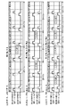
例えば、図9(a)に示すように、領域A及び領域Bにおいて吸入空気量又は機関回転速度が比較的低い場合には、所定燃焼サイクル数NをNL(例えば、3)に設定し、図9(c)に示すように、領域A及び領域Bにおいて吸入空気量又は機関回転速度が比較的高い場合には、所定燃焼サイクル数NをNH(例えば、1)に設定し、図9(b)に示すように、領域A及び領域Bにおい吸入空気量又は機関回転速度が中程度の場合には、所定燃焼サイクル数NをNM(例えば、2)に設定して、NL,NM,NHの大小関係がNL<NM<NHとなるようにすることができる。
ステップS104~ステップS109を実行することで、内燃機関10の運転状態が領域A又は領域Bに該当する場合の第1燃料噴射弁28及び第2燃料噴射弁30に対する噴射パルス信号の設定が終了する。
このようなECU40によれば、各燃焼サイクルにおいて第1燃料噴射弁28が燃料を噴射する噴射時期と第2燃料噴射弁30が燃料を噴射する噴射時期との2つの噴射時期に位相差を設けつつ、内燃機関10の運転状態に応じて、2つの噴射時期を所定燃焼サイクル数N毎に交互に入れ替えるように、噴射パルス信号を設定している。
したがって、各燃焼サイクルにおいて、吸気行程における噴射期間が比較的長い第2次噴射で燃料を噴射して、噴射燃料の一部が吸気流によって一方の吸気ポートのポート内壁に付着しても、所定燃焼サイクル数Nの経過後には、噴射モードを吸気行程における噴射期間が比較的短い第1次噴射に入れ替えて、付着燃料の気化を促進させることができる。
このため、空気と燃料との混合促進を考慮しつつ、一方の吸気ポートの付着部位において噴射燃料が燃焼サイクル毎に次々と付着して平衡付着量が増大すること抑制できるので、過渡運転時の空燃比変動を抑えて、排気エミッションや燃費性能を改善することが可能となる。
したがって、各燃焼サイクルにおいて、吸気行程における噴射期間が比較的長い第2次噴射で燃料を噴射して、噴射燃料の一部が吸気流によって一方の吸気ポートのポート内壁に付着しても、所定燃焼サイクル数Nの経過後には、噴射モードを吸気行程における噴射期間が比較的短い第1次噴射に入れ替えて、付着燃料の気化を促進させることができる。
このため、空気と燃料との混合促進を考慮しつつ、一方の吸気ポートの付着部位において噴射燃料が燃焼サイクル毎に次々と付着して平衡付着量が増大すること抑制できるので、過渡運転時の空燃比変動を抑えて、排気エミッションや燃費性能を改善することが可能となる。
なお、前述の実施形態において、第1次噴射では、一方の燃料噴射弁が排気行程において燃料の噴射を開始していたが、これに限られず、第1次噴射では、単に、一方の燃料噴射弁が他方の燃料噴射弁よりも先に噴射を開始するようにしてもよい。例えば、第1次噴射では、一方の燃料噴射弁が吸気行程のうち吸気バルブ20の開弁度が比較的小さい期間で燃料を噴射するようにしてもよい。この場合、第2次噴射では、他方の燃料噴射弁の噴射期間における吸入空気量が一方の燃料噴射弁の噴射期間における吸入空気量よりも大きくなるように、例えば、吸気バルブ20の開弁度が比較的大きくなる期間で、他方の燃料噴射弁が燃料を噴射するようにしてもよい。
このように第1次噴射及び第2次噴射を行う場合でも、第1燃料噴射弁28及び第2燃料噴射弁30の噴射モードを固定してしまうと、第2次噴射により噴射期間中の吸入空気量が多くなる吸気ポートでは燃料の平衡付着量が増大してしまうので、前述の実施形態による噴射パルス信号の設定処理により、噴射モードを所定燃焼サイクル毎に交互に入れ替えることが効果的である。
このように第1次噴射及び第2次噴射を行う場合でも、第1燃料噴射弁28及び第2燃料噴射弁30の噴射モードを固定してしまうと、第2次噴射により噴射期間中の吸入空気量が多くなる吸気ポートでは燃料の平衡付着量が増大してしまうので、前述の実施形態による噴射パルス信号の設定処理により、噴射モードを所定燃焼サイクル毎に交互に入れ替えることが効果的である。
内燃機関10の運転状態を規定するパラメータとしては、前述の機関回転速度と吸入空気量との組み合せに限定されず、機関回転速度に対して、例えば、内燃機関10の発生トルク、吸気管12の負圧、スロットル開度等、内燃機関10の負荷(機関負荷)を示すパラメータを組み合せることができる。
前述の実施形態で、内燃機関10の運転状態を領域A、領域B及び領域Cに区分して、それぞれの領域に対応する基本噴射パルス幅TPをTPA,TPB,TPCの3つに設定したが、これに替えて、内燃機関10の運転状態を2つ、又は4つ以上の領域に区分して、それぞれの領域に対応する基本噴射パルス幅TPを設定してもよい。
領域Aと領域Bとに区分して設定される燃料分担率P、領域Bを吸入空気量又は機関回転速度が比較的低い場合と高い場合とに区分して設定される第1次噴射の噴射終了時期t1eB、領域Aを吸入空気量又は機関回転速度が比較的低い場合と高い場合とに区分して設定される第1次噴射の噴射開始時期t1sB、並びに、領域A及び領域Bを吸入空気量又は機関回転速度が比較的低い場合と高い場合と中程度とに区分して設定される所定燃焼サイクル数Nについても、基本噴射パルス幅TPと同様に、複数であれば、区分数を増減して設定可能である。
領域Aと領域Bとに区分して設定される燃料分担率P、領域Bを吸入空気量又は機関回転速度が比較的低い場合と高い場合とに区分して設定される第1次噴射の噴射終了時期t1eB、領域Aを吸入空気量又は機関回転速度が比較的低い場合と高い場合とに区分して設定される第1次噴射の噴射開始時期t1sB、並びに、領域A及び領域Bを吸入空気量又は機関回転速度が比較的低い場合と高い場合と中程度とに区分して設定される所定燃焼サイクル数Nについても、基本噴射パルス幅TPと同様に、複数であれば、区分数を増減して設定可能である。
図4のフローチャートは、噴射パルス信号の設定処理の一例を示したものであり、例えば、最初に領域A~領域Cを判定し、判定された領域に応じて噴射パルス幅信号の設定処理を実行してもよい。すなわち、例えば領域Aであると判定されれば、第1のステップでステップS101のように噴射パルス幅TIAを算出し、第2のステップでステップS104のように燃料分担率PAを設定して、第1次噴射の噴射パルス幅TIA1及び第2次噴射の噴射パルス幅TIA2を演算し、第3のステップでステップS107のように第1次噴射の噴射開始時期t1sAを設定して、第1次噴射の噴射終了時期t1eAを演算し、第4のステップでステップS108のように第2次噴射の噴射終了時期t2eを設定して、第2次噴射の噴射開始時期t2sを演算し、第5のステップでステップS109のように噴射時期の入れ替えを行ってもよい。同様に、領域Bと判定された場合には、ステップS101、ステップS104、ステップS106、ステップS108、ステップS109の各処理をこの順番で実行し、領域Cと判定された場合には、ステップS101、ステップS103の各処理をこの順番で実行してもよい。
10…内燃機関、14…第1吸気ポート、16…第2吸気ポート、18…気筒、20…吸気バルブ、28…第1燃料噴射弁、30…第2燃料噴射弁、36…燃焼室、40…ECU、42…クランク角センサ、44…エアフローセンサ
Claims (12)
- 気筒毎に第1吸気通路と第2吸気通路とを備え、前記第1吸気通路に第1燃料噴射弁を配置し、前記第2吸気通路に第2燃料噴射弁を配置した内燃機関に対して、前記第1燃料噴射弁及び前記第2燃料噴射弁に燃料の噴射を行わせる燃料噴射制御装置であって、
各燃焼サイクルにおいて前記第1燃料噴射弁が燃料を噴射する噴射時期と前記第2燃料噴射弁が燃料を噴射する噴射時期との2つの噴射時期に位相差を設けつつ、前記2つの噴射時期を所定燃焼サイクル数毎に交互に入れ替えるように、前記第1燃料噴射弁及び前記第2燃料噴射弁に対する指示信号を設定する指示信号設定手段を備えたことを特徴とする、燃料噴射制御装置。 - 前記指示信号設定手段は、前記内燃機関の運転状態に応じて前記所定燃焼サイクル数を設定することを特徴とする、請求項1に記載の燃料噴射制御装置。
- 前記指示信号設定手段は、機関負荷又は機関回転速度が高くなるに従って、前記所定燃焼サイクル数を減少させて設定することを特徴とする、請求項2に記載の燃料噴射制御装置。
- 前記指示信号設定手段は、前記第1燃料噴射弁及び前記第2燃料噴射弁のうち一方の燃料噴射弁が他方の燃料噴射弁よりも先に排気行程中で噴射を開始し、吸気行程中における前記他方の燃料噴射弁の噴射期間が前記一方の燃料噴射弁の噴射期間よりも長くなるように、前記指示信号を設定することを特徴とする、請求項1に記載の燃料噴射制御装置。
- 前記指示信号設定手段は、前記他方の燃料噴射弁が燃料を噴射している期間である第2噴射期間に対して、前記一方の燃料噴射弁が燃料を噴射している期間である第1噴射期間の比率が、前記内燃機関の運転状態に応じて変化するように、前記指示信号を設定することを特徴とする、請求項4に記載の燃料噴射制御装置。
- 前記指示信号設定手段は、前記第1噴射期間が前記第2噴射期間以上となるように制限し、機関負荷又は機関回転速度が高くなるに従って前記比率が低下するように、前記指示信号を設定することを特徴とする、請求項5に記載の燃料噴射制御装置。
- 前記指示信号設定手段は、前記内燃機関の運転状態に応じて、前記一方の燃料噴射弁による燃料噴射を終了する時期が変化するように、前記指示信号を設定することを特徴とする、請求項5に記載の燃料噴射制御装置。
- 前記指示信号設定手段は、機関負荷又は機関回転速度が高くなるに従って、前記一方の燃料噴射弁による燃料噴射を終了する時期が遅くなるように、前記指示信号を設定することを特徴とする、請求項7に記載の燃料噴射制御装置。
- 前記指示信号設定手段は、前記内燃機関の運転状態に応じて、前記一方の燃料噴射弁による燃料の噴射を開始する時期が変化するように、前記指示信号を設定することを特徴とする、請求項5に記載の燃料噴射制御装置。
- 前記指示信号設定手段は、機関負荷又は機関回転速度が高くなるに従って、前記一方の燃料噴射弁による燃料噴射を開始する時期が早くなるように、前記指示信号を設定することを特徴とする、請求項9に記載の燃料噴射制御装置。
- 前記指示信号設定手段は、前記他方の燃料噴射弁による燃料噴射を終了する時期が吸気行程中の一定時期に固定されることを特徴とする、請求項4に記載の燃料噴射制御装置。
- 前記内燃機関の運転状態が高負荷高回転領域にある場合、前記2つの噴射時期の入れ替えを停止することを特徴とする、請求項1に記載の燃料噴射制御装置。
Applications Claiming Priority (2)
| Application Number | Priority Date | Filing Date | Title |
|---|---|---|---|
| JP2016051374A JP6461843B2 (ja) | 2016-03-15 | 2016-03-15 | 燃料噴射制御装置 |
| JP2016-051374 | 2016-03-15 |
Publications (1)
| Publication Number | Publication Date |
|---|---|
| WO2017159450A1 true WO2017159450A1 (ja) | 2017-09-21 |
Family
ID=59850839
Family Applications (1)
| Application Number | Title | Priority Date | Filing Date |
|---|---|---|---|
| PCT/JP2017/008946 Ceased WO2017159450A1 (ja) | 2016-03-15 | 2017-03-07 | 燃料噴射制御装置 |
Country Status (2)
| Country | Link |
|---|---|
| JP (1) | JP6461843B2 (ja) |
| WO (1) | WO2017159450A1 (ja) |
Families Citing this family (5)
| Publication number | Priority date | Publication date | Assignee | Title |
|---|---|---|---|---|
| JP7031431B2 (ja) * | 2018-03-27 | 2022-03-08 | トヨタ自動車株式会社 | 内燃機関の制御装置 |
| US10968854B2 (en) * | 2018-03-27 | 2021-04-06 | Toyota Jidosha Kabushiki Kaisha | Controller and control method for internal combustion engine |
| JP6994447B2 (ja) * | 2018-09-21 | 2022-01-14 | 日立Astemo株式会社 | 内燃機関制御装置 |
| JP7120861B2 (ja) * | 2018-09-21 | 2022-08-17 | 日立Astemo株式会社 | 内燃機関制御装置 |
| JP7202857B2 (ja) * | 2018-11-26 | 2023-01-12 | 日立Astemo株式会社 | 内燃機関制御装置 |
Citations (3)
| Publication number | Priority date | Publication date | Assignee | Title |
|---|---|---|---|---|
| JP2005180285A (ja) * | 2003-12-18 | 2005-07-07 | Fuji Heavy Ind Ltd | 過給機付エンジンの制御装置 |
| JP2007292058A (ja) * | 2006-03-29 | 2007-11-08 | Denso Corp | 燃料噴射制御装置 |
| JP2012229653A (ja) * | 2011-04-26 | 2012-11-22 | Toyota Motor Corp | 内燃機関の制御装置 |
-
2016
- 2016-03-15 JP JP2016051374A patent/JP6461843B2/ja active Active
-
2017
- 2017-03-07 WO PCT/JP2017/008946 patent/WO2017159450A1/ja not_active Ceased
Patent Citations (3)
| Publication number | Priority date | Publication date | Assignee | Title |
|---|---|---|---|---|
| JP2005180285A (ja) * | 2003-12-18 | 2005-07-07 | Fuji Heavy Ind Ltd | 過給機付エンジンの制御装置 |
| JP2007292058A (ja) * | 2006-03-29 | 2007-11-08 | Denso Corp | 燃料噴射制御装置 |
| JP2012229653A (ja) * | 2011-04-26 | 2012-11-22 | Toyota Motor Corp | 内燃機関の制御装置 |
Also Published As
| Publication number | Publication date |
|---|---|
| JP6461843B2 (ja) | 2019-01-30 |
| JP2017166388A (ja) | 2017-09-21 |
Similar Documents
| Publication | Publication Date | Title |
|---|---|---|
| JP5161278B2 (ja) | 内燃機関の燃料噴射制御装置 | |
| JP6461843B2 (ja) | 燃料噴射制御装置 | |
| JP5541535B2 (ja) | 内燃機関の燃料噴射制御装置 | |
| WO2015001728A1 (ja) | 筒内噴射エンジンの制御装置 | |
| JP4787867B2 (ja) | 燃料噴射弁、内燃機関の燃料噴射装置及び内燃機関の制御装置 | |
| JP2009228447A (ja) | 内燃機関の燃料噴射制御装置 | |
| JP4525441B2 (ja) | 内燃機関 | |
| JP5637222B2 (ja) | 内燃機関の制御装置 | |
| JP2007009807A (ja) | 内燃機関の制御装置 | |
| WO2013054391A1 (ja) | 内燃機関の制御装置 | |
| JP5047997B2 (ja) | 内燃機関の燃料噴射制御装置 | |
| JP2009257100A (ja) | 内燃機関の噴射制御装置 | |
| JP5273060B2 (ja) | 内燃機関の空燃比ばらつき検出装置 | |
| JP2004340065A (ja) | 水素エンジン用制御装置 | |
| JP5450548B2 (ja) | 内燃機関の燃料噴射制御装置 | |
| JP4501107B2 (ja) | 内燃機関の燃料噴射制御方法 | |
| JP6274401B2 (ja) | エンジンの燃料噴射制御装置 | |
| JP2012117472A (ja) | 内燃機関の制御装置 | |
| JP5672930B2 (ja) | 内燃機関の制御装置 | |
| JP2019094783A (ja) | 内燃機関の燃料噴射制御装置 | |
| JP2010168931A (ja) | 火花点火式内燃機関の点火時期制御装置 | |
| JP4415803B2 (ja) | 内燃機関の制御装置 | |
| JP2010053758A (ja) | 内燃機関の燃料噴射量制御装置 | |
| JP6448322B2 (ja) | 内燃機関の制御装置 | |
| JP5894041B2 (ja) | 内燃機関の制御装置 |
Legal Events
| Date | Code | Title | Description |
|---|---|---|---|
| NENP | Non-entry into the national phase |
Ref country code: DE |
|
| 121 | Ep: the epo has been informed by wipo that ep was designated in this application |
Ref document number: 17766452 Country of ref document: EP Kind code of ref document: A1 |
|
| 122 | Ep: pct application non-entry in european phase |
Ref document number: 17766452 Country of ref document: EP Kind code of ref document: A1 |