WO2017159206A1 - 流量制御弁および冷却システム - Google Patents
流量制御弁および冷却システム Download PDFInfo
- Publication number
- WO2017159206A1 WO2017159206A1 PCT/JP2017/005801 JP2017005801W WO2017159206A1 WO 2017159206 A1 WO2017159206 A1 WO 2017159206A1 JP 2017005801 W JP2017005801 W JP 2017005801W WO 2017159206 A1 WO2017159206 A1 WO 2017159206A1
- Authority
- WO
- WIPO (PCT)
- Prior art keywords
- communication hole
- sub
- valve body
- main
- opening
- Prior art date
- Legal status (The legal status is an assumption and is not a legal conclusion. Google has not performed a legal analysis and makes no representation as to the accuracy of the status listed.)
- Ceased
Links
Images




Classifications
-
- F—MECHANICAL ENGINEERING; LIGHTING; HEATING; WEAPONS; BLASTING
- F16—ENGINEERING ELEMENTS AND UNITS; GENERAL MEASURES FOR PRODUCING AND MAINTAINING EFFECTIVE FUNCTIONING OF MACHINES OR INSTALLATIONS; THERMAL INSULATION IN GENERAL
- F16K—VALVES; TAPS; COCKS; ACTUATING-FLOATS; DEVICES FOR VENTING OR AERATING
- F16K11/00—Multiple-way valves, e.g. mixing valves; Pipe fittings incorporating such valves
- F16K11/02—Multiple-way valves, e.g. mixing valves; Pipe fittings incorporating such valves with all movable sealing faces moving as one unit
- F16K11/08—Multiple-way valves, e.g. mixing valves; Pipe fittings incorporating such valves with all movable sealing faces moving as one unit comprising only taps or cocks
-
- F—MECHANICAL ENGINEERING; LIGHTING; HEATING; WEAPONS; BLASTING
- F16—ENGINEERING ELEMENTS AND UNITS; GENERAL MEASURES FOR PRODUCING AND MAINTAINING EFFECTIVE FUNCTIONING OF MACHINES OR INSTALLATIONS; THERMAL INSULATION IN GENERAL
- F16K—VALVES; TAPS; COCKS; ACTUATING-FLOATS; DEVICES FOR VENTING OR AERATING
- F16K5/00—Plug valves; Taps or cocks comprising only cut-off apparatus having at least one of the sealing faces shaped as a more or less complete surface of a solid of revolution, the opening and closing movement being predominantly rotary
- F16K5/04—Plug valves; Taps or cocks comprising only cut-off apparatus having at least one of the sealing faces shaped as a more or less complete surface of a solid of revolution, the opening and closing movement being predominantly rotary with plugs having cylindrical surfaces; Packings therefor
- F16K5/0407—Plug valves; Taps or cocks comprising only cut-off apparatus having at least one of the sealing faces shaped as a more or less complete surface of a solid of revolution, the opening and closing movement being predominantly rotary with plugs having cylindrical surfaces; Packings therefor with particular plug arrangements, e.g. particular shape or built-in means
-
- F—MECHANICAL ENGINEERING; LIGHTING; HEATING; WEAPONS; BLASTING
- F01—MACHINES OR ENGINES IN GENERAL; ENGINE PLANTS IN GENERAL; STEAM ENGINES
- F01P—COOLING OF MACHINES OR ENGINES IN GENERAL; COOLING OF INTERNAL-COMBUSTION ENGINES
- F01P7/00—Controlling of coolant flow
- F01P7/14—Controlling of coolant flow the coolant being liquid
- F01P7/16—Controlling of coolant flow the coolant being liquid by thermostatic control
- F01P7/165—Controlling of coolant flow the coolant being liquid by thermostatic control characterised by systems with two or more loops
-
- F—MECHANICAL ENGINEERING; LIGHTING; HEATING; WEAPONS; BLASTING
- F16—ENGINEERING ELEMENTS AND UNITS; GENERAL MEASURES FOR PRODUCING AND MAINTAINING EFFECTIVE FUNCTIONING OF MACHINES OR INSTALLATIONS; THERMAL INSULATION IN GENERAL
- F16K—VALVES; TAPS; COCKS; ACTUATING-FLOATS; DEVICES FOR VENTING OR AERATING
- F16K11/00—Multiple-way valves, e.g. mixing valves; Pipe fittings incorporating such valves
- F16K11/02—Multiple-way valves, e.g. mixing valves; Pipe fittings incorporating such valves with all movable sealing faces moving as one unit
- F16K11/06—Multiple-way valves, e.g. mixing valves; Pipe fittings incorporating such valves with all movable sealing faces moving as one unit comprising only sliding valves, i.e. sliding closure elements
- F16K11/072—Multiple-way valves, e.g. mixing valves; Pipe fittings incorporating such valves with all movable sealing faces moving as one unit comprising only sliding valves, i.e. sliding closure elements with pivoted closure members
- F16K11/076—Multiple-way valves, e.g. mixing valves; Pipe fittings incorporating such valves with all movable sealing faces moving as one unit comprising only sliding valves, i.e. sliding closure elements with pivoted closure members with sealing faces shaped as surfaces of solids of revolution
-
- F—MECHANICAL ENGINEERING; LIGHTING; HEATING; WEAPONS; BLASTING
- F16—ENGINEERING ELEMENTS AND UNITS; GENERAL MEASURES FOR PRODUCING AND MAINTAINING EFFECTIVE FUNCTIONING OF MACHINES OR INSTALLATIONS; THERMAL INSULATION IN GENERAL
- F16K—VALVES; TAPS; COCKS; ACTUATING-FLOATS; DEVICES FOR VENTING OR AERATING
- F16K11/00—Multiple-way valves, e.g. mixing valves; Pipe fittings incorporating such valves
- F16K11/02—Multiple-way valves, e.g. mixing valves; Pipe fittings incorporating such valves with all movable sealing faces moving as one unit
- F16K11/08—Multiple-way valves, e.g. mixing valves; Pipe fittings incorporating such valves with all movable sealing faces moving as one unit comprising only taps or cocks
- F16K11/085—Multiple-way valves, e.g. mixing valves; Pipe fittings incorporating such valves with all movable sealing faces moving as one unit comprising only taps or cocks with cylindrical plug
-
- F—MECHANICAL ENGINEERING; LIGHTING; HEATING; WEAPONS; BLASTING
- F16—ENGINEERING ELEMENTS AND UNITS; GENERAL MEASURES FOR PRODUCING AND MAINTAINING EFFECTIVE FUNCTIONING OF MACHINES OR INSTALLATIONS; THERMAL INSULATION IN GENERAL
- F16K—VALVES; TAPS; COCKS; ACTUATING-FLOATS; DEVICES FOR VENTING OR AERATING
- F16K11/00—Multiple-way valves, e.g. mixing valves; Pipe fittings incorporating such valves
- F16K11/02—Multiple-way valves, e.g. mixing valves; Pipe fittings incorporating such valves with all movable sealing faces moving as one unit
- F16K11/08—Multiple-way valves, e.g. mixing valves; Pipe fittings incorporating such valves with all movable sealing faces moving as one unit comprising only taps or cocks
- F16K11/087—Multiple-way valves, e.g. mixing valves; Pipe fittings incorporating such valves with all movable sealing faces moving as one unit comprising only taps or cocks with spherical plug
- F16K11/0873—Multiple-way valves, e.g. mixing valves; Pipe fittings incorporating such valves with all movable sealing faces moving as one unit comprising only taps or cocks with spherical plug the plug being only rotatable around one spindle
- F16K11/0876—Multiple-way valves, e.g. mixing valves; Pipe fittings incorporating such valves with all movable sealing faces moving as one unit comprising only taps or cocks with spherical plug the plug being only rotatable around one spindle one connecting conduit having the same axis as the spindle
-
- F—MECHANICAL ENGINEERING; LIGHTING; HEATING; WEAPONS; BLASTING
- F16—ENGINEERING ELEMENTS AND UNITS; GENERAL MEASURES FOR PRODUCING AND MAINTAINING EFFECTIVE FUNCTIONING OF MACHINES OR INSTALLATIONS; THERMAL INSULATION IN GENERAL
- F16K—VALVES; TAPS; COCKS; ACTUATING-FLOATS; DEVICES FOR VENTING OR AERATING
- F16K27/00—Construction of housing; Use of materials therefor
- F16K27/06—Construction of housing; Use of materials therefor of taps or cocks
- F16K27/065—Construction of housing; Use of materials therefor of taps or cocks with cylindrical plugs
-
- F—MECHANICAL ENGINEERING; LIGHTING; HEATING; WEAPONS; BLASTING
- F16—ENGINEERING ELEMENTS AND UNITS; GENERAL MEASURES FOR PRODUCING AND MAINTAINING EFFECTIVE FUNCTIONING OF MACHINES OR INSTALLATIONS; THERMAL INSULATION IN GENERAL
- F16K—VALVES; TAPS; COCKS; ACTUATING-FLOATS; DEVICES FOR VENTING OR AERATING
- F16K31/00—Actuating devices; Operating means; Releasing devices
- F16K31/02—Actuating devices; Operating means; Releasing devices electric; magnetic
- F16K31/04—Actuating devices; Operating means; Releasing devices electric; magnetic using a motor
- F16K31/041—Actuating devices; Operating means; Releasing devices electric; magnetic using a motor for rotating valves
-
- F—MECHANICAL ENGINEERING; LIGHTING; HEATING; WEAPONS; BLASTING
- F16—ENGINEERING ELEMENTS AND UNITS; GENERAL MEASURES FOR PRODUCING AND MAINTAINING EFFECTIVE FUNCTIONING OF MACHINES OR INSTALLATIONS; THERMAL INSULATION IN GENERAL
- F16K—VALVES; TAPS; COCKS; ACTUATING-FLOATS; DEVICES FOR VENTING OR AERATING
- F16K31/00—Actuating devices; Operating means; Releasing devices
- F16K31/44—Mechanical actuating means
- F16K31/53—Mechanical actuating means with toothed gearing
- F16K31/535—Mechanical actuating means with toothed gearing for rotating valves
-
- F—MECHANICAL ENGINEERING; LIGHTING; HEATING; WEAPONS; BLASTING
- F01—MACHINES OR ENGINES IN GENERAL; ENGINE PLANTS IN GENERAL; STEAM ENGINES
- F01P—COOLING OF MACHINES OR ENGINES IN GENERAL; COOLING OF INTERNAL-COMBUSTION ENGINES
- F01P7/00—Controlling of coolant flow
- F01P7/14—Controlling of coolant flow the coolant being liquid
- F01P2007/146—Controlling of coolant flow the coolant being liquid using valves
-
- F—MECHANICAL ENGINEERING; LIGHTING; HEATING; WEAPONS; BLASTING
- F16—ENGINEERING ELEMENTS AND UNITS; GENERAL MEASURES FOR PRODUCING AND MAINTAINING EFFECTIVE FUNCTIONING OF MACHINES OR INSTALLATIONS; THERMAL INSULATION IN GENERAL
- F16K—VALVES; TAPS; COCKS; ACTUATING-FLOATS; DEVICES FOR VENTING OR AERATING
- F16K27/00—Construction of housing; Use of materials therefor
- F16K27/12—Covers for housings
Definitions
- the present invention relates to a flow control valve and a cooling system.
- Patent Document 1 discloses a flow control valve having a valve body rotatably provided in a valve housing.
- the valve housing is integrally formed with a hot water inlet pipe through which hot water from the engine flows into the flow control valve and a hot water outlet pipe through which the flowing hot water flows out toward the heat exchanger.
- Seal members made of an elastic material such as rubber are provided between the hot water inlet pipe and the valve body, and between the hot water outlet pipe and the valve body.
- An object of the present invention is to provide a flow control valve and a cooling system that can reduce torque when the valve body in the housing is rotationally driven.
- the flow control valve is provided between the main communication hole and the valve body, and fluid leaks from the main communication hole or the main opening to the gap.
- the valve body that is provided with a seal member that suppresses the rotation of the valve body and is rotated by the drive mechanism communicates the first sub-communication hole and the first sub-opening regardless of the rotational position of the valve body, and Accordingly, the communication state between the main communication hole and the main opening and the communication state between the second sub communication hole and the second sub opening are changed, and the inner peripheral surface of the valve body housing portion and the outer peripheral surface of the valve body peripheral wall are changed.
- the flow control valve includes a contact seal member that is provided between the housing and the valve body and seals between the valve body and the housing by contacting the outer peripheral surface of the valve body.
- the body changes the communication state of the main communication hole and the main opening and the communication state of the sub communication hole and the plurality of sub openings according to the rotation position, and the sub communication hole is always in communication with the first sub opening.
- the first sub-communication hole, and a second sub-communication hole that can be switched between a state communicating with the second sub-opening and a state not communicating according to the rotational position of the valve body, the second sub-communication hole is In the state where the main communication hole communicates with the main opening and the second sub communication hole does not communicate with the second sub opening, the inner peripheral surface of the valve body housing portion and the outer peripheral surface of the valve body peripheral wall
- the fluid can flow through a non-contact seal formed between the two.
- the cooling system is provided so as to pass through the heat exchanger that cools the inflowing fluid and the heat exchanger, and the fluid cooled in the heat exchanger is circulated to cool the heat source.
- a flow rate control valve for controlling the flow rate of the fluid circulating in the circuit.
- the flow rate control valve is provided between the housing and the valve body, and is a gap from the main communication hole or the main opening.
- the valve body that is provided with a seal member that suppresses leakage to the valve and is rotationally driven by the drive mechanism communicates the first sub-communication hole and the first sub-opening regardless of the rotational position of the valve body.
- the communication state between the main communication hole and the main opening and the communication state between the second sub communication hole and the second sub opening are changed, and the inner peripheral surface of the valve body housing part and the valve body
- the fluid leaking into the second sub-communication hole through the gap formed between the outer peripheral surface of the peripheral wall Pressure loss is caused by the fluid, the fluid leaks into the second sub-communication hole when the main communication hole communicates with the main opening, and the second sub-communication hole does not communicate with the second sub-opening.
- the amount to be dispensed was set according to the amount allowed in the device to which the main communication hole is connected.
- the drive mechanism can be reduced in size.
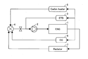
- FIG. 2 is a schematic diagram illustrating a configuration of a circulation circuit for cooling water that cools the engine according to the first embodiment.
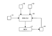
- FIG. 2 is a control block diagram for controlling the mechanical control valve according to the first embodiment.
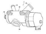
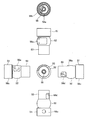
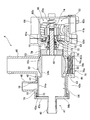
- 1 is an external view of a mechanical control valve of Example 1.
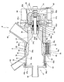
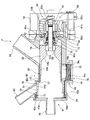
- FIG. 1 is a cross-sectional view of a mechanical control valve of Example 1.
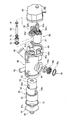
- FIG. 1 is an exploded perspective view of a mechanical control valve of Example 1.
- FIG. 1 is a view showing a valve body of Example 1.
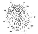
- FIG. FIG. 2 is a diagram showing a drive mechanism of Example 1.
- FIG. 3 is a diagram showing an operating state of the mechanical control valve of Example 1.
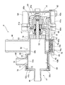
- FIG. 3 is a cross-sectional view of a mechanical control valve of Example 2.
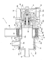
- FIG. 3 is a cross-sectional view of a mechanical control valve of Example 2.
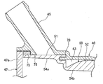
- FIG. 6 is a cross-sectional view of the vicinity of a second sub-communication hole of Example 3.
- FIG. 6 is a sectional view of a mechanical control valve of Example 4.
- FIG. 6 is a sectional view of a mechanical control valve of Example 4.
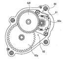
- FIG. 10 is a diagram showing a drive mechanism of Example 5.
- FIG. 10 is a schematic diagram showing a configuration of a circulating circuit for cooling water for cooling the engine of Example 6. It is sectional drawing of the mechanical control valve of another Example. It is sectional drawing of the mechanical control valve of another Example.
- FIG. 1 is a schematic diagram showing a configuration of a circulation circuit of cooling water for cooling the engine 1. Cooling water is pumped to the engine 1 by the pump 2. Cooling water that has cooled the engine 1 is sent to an electronically controlled throttle body (ETB) 3. The electronically controlled throttle body 3 controls the throttle opening according to the temperature of the cooling water flowing out from the engine 1. The cooling water flowing into the electronically controlled throttle body 3 is returned to the suction side of the pump 2. Cooling water flowing out from the engine 1 is sent to a mechanical control valve (MCV) 4.
- MCV mechanical control valve
- the mechanical control valve 4 is in a fully closed state in which the entire amount of cooling water flowing out from the engine 1 is returned to the engine 1, a first open state in which the cooling water is supplied to the cabin heater 5, and an oil cooler (OC) that adds cooling water to the cabin heater 5.
- the second valve open state to be supplied to 6 and the fully open state to supply the coolant to the radiator 7 in addition to the cabin heater 5 and the oil cooler 6 are switched.
- the cabin heater 5 is a heat exchanger that heats the air in the vehicle interior in order to heat the vehicle interior.
- the oil cooler 6 is a heat exchanger that cools engine oil that lubricates the inside of the engine 1.
- the radiator 7 is a heat exchanger that cools cooling water using, for example, traveling wind of the vehicle.
- FIG. 2 is a control block diagram for controlling the mechanical control valve 4.
- the mechanical control valve 4 is controlled by the engine control unit 10 that controls the engine 1 to switch the aforementioned fully closed state, first valve open state, second valve open state, and fully open state.
- the engine control unit 10 inputs cooling water temperature information from a water temperature sensor 11 that detects the temperature of the cooling water provided in the electronic control throttle body 3.
- the water temperature sensor 11 is not limited to that provided in the electronic control throttle body 3, but may be provided in another place.
- the engine control unit 10 inputs engine load information from the engine load sensor 12.
- the engine load sensor 12 may estimate the engine load from the engine negative pressure or the throttle opening and output it as engine load information.
- the engine control unit 10 inputs road surface state information from the road surface state determination sensor 13.
- the road surface condition determination sensor 13 is not particularly limited, such as a sensor that determines the road surface condition by irradiating the road surface with infrared rays or the like, or a sensor that determines the road surface condition from a tire slip rate or the like.
- the engine control unit 10 determines the target state of the mechanical control valve 4 (fully closed state, first valve open state, second valve open state, from the above-described coolant temperature information, engine load information, road surface condition information, etc. Set to the fully open state.
- the engine control unit 10 controls the mechanical control valve 4 based on the angle signal information of the angle sensor 14 provided in the mechanical control valve 4 so that the mechanical control valve 4 is set to a target state.
- the angle sensor 14 is provided in the mechanical control valve 4 and detects the rotational position of the valve body 50 in the mechanical control valve 4.
- the fully closed state, the first valve open state, the second valve open state, and the fully open state of the mechanical control valve 4 are switched according to the turning position of the valve body 50.
- FIG. 3 is an external view of the mechanical control valve 4.
- FIG. 4 is a cross-sectional view of the mechanical control valve 4.
- FIG. 5 is an exploded perspective view of the mechanical control valve 4.
- FIG. 6 is a view showing the valve body 50.
- FIG. 7 is a diagram showing the drive mechanism 60.
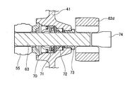
- FIG. 8 is a view around the drive shaft 63.
- the mechanical control valve 4 includes a housing 40 formed in a hollow shape, a valve body 50 rotatably accommodated in the housing 40, and a drive mechanism 60 that is provided on one end side of the valve body and rotates the valve body 50. And have.
- the housing 40 is manufactured by casting using, for example, an aluminum alloy material.
- the housing 40 is generally formed in a bottomed cup shape.
- the inside of the housing 40 is open at one end side, and most of the other end side is covered with a bottom 41.
- An insertion hole 41a communicating with the outside is formed in the bottom 41.
- the housing 40 includes a housing peripheral wall, and a valve body accommodating portion 43 is formed by the inner peripheral surface 42 and the bottom portion 41 of the housing peripheral wall.
- a main communication hole 44 is provided on the outer peripheral surface of the housing 40.
- the main communication hole 44 is formed so as to extend in the radial direction of the housing 40.
- the main communication hole 44 is tubular and opens into the valve body housing portion 43.
- the main communication hole 44 is provided substantially at the center with respect to the axial direction of the housing 40.
- the main communication hole 44 is connected to the engine 1.
- the coolant that has cooled the engine 1 flows into the main communication hole 44.
- a second sub communication hole 45 is provided on the outer peripheral surface of the housing 40.
- the second sub communication hole 45 is formed to extend (obliquely) so as to fall to one end side (opening side) with respect to the radial direction of the housing 40.
- the second sub communication hole 45 is tubular and opens into the valve body accommodating portion 43.
- the opening portion of the second sub-communication hole 45 to the valve body housing portion 43 is provided on one end side in the axial direction of the housing 40 with respect to the opening portion of the main communication hole 44 to the valve body housing portion 43.
- the second sub communication hole 45 is connected to the oil cooler 6. Cooling water flows out from the second sub-communication hole 45 to the oil cooler 6.
- a third sub-communication hole 46 is provided on the outer peripheral surface of the housing 40.
- the third auxiliary communication hole 46 is formed to extend (obliquely) so as to fall down on the other end side (bottom 41 side) with respect to the radial direction of the housing 40.
- the third sub communication hole 46 is tubular and opens into the valve body housing portion 43.
- the opening of the third sub-communication hole 46 to the valve body accommodating portion 43 is provided on the other end side in the axial direction of the housing 40 with respect to the opening of the main communicating hole 44 to the valve body accommodating portion 43. That is, the second secondary communication hole 45 is provided on the opposite side of the third secondary communication hole 46 with the main communication hole 44 interposed therebetween in the axial direction of the housing 40.
- the third sub communication hole 46 is connected to the radiator 7.
- the open end of the inner peripheral surface 42 constitutes a bearing holding portion 42a.
- a large diameter portion 42b is formed on the inner peripheral surface 42 at a position adjacent to the bearing holding portion 42a.
- the inner diameter of the large diameter portion 42b is smaller than the inner diameter of the bearing holding portion 42a.
- a small-diameter portion 42d is formed on the inner peripheral surface 42 at a position adjacent to the bottom portion 41.
- the inner diameter of the small diameter portion 42d is smaller than the inner diameter of the large diameter portion 42b.
- a spherical portion 42c is formed between the large diameter portion 42b and the small diameter portion 42d.
- the spherical surface portion 42c has a spherical inner surface.
- the opening on the one end side of the valve body housing portion 43 is closed by a cover 47 that forms a housing peripheral wall after the valve body 50 is housed in the valve body housing portion 43.
- the cover 47 is manufactured by casting using, for example, an aluminum alloy material.
- the outer diameter of the cover 47 is formed to be approximately the same as the inner diameter of the bearing holding portion 42a.
- the cover 47 is press-fitted into the bearing holding portion 42a.
- a first sub-communication hole 48 extending outward in the axial direction of the housing 40 is formed at the center of the disc-shaped lid 47a.
- the first sub communication hole 48 is connected to the cabin heater 5. Coolant flows out from the first sub-communication hole 48 to the cabin heater 5.
- a motor housing portion 49 is formed at a position shifted in the radial direction with respect to the axial direction of the valve body housing portion 43.
- the motor housing portion 49 is formed in a bottomed cup shape, and the other end side is open.
- the valve body housing portion 43 and the motor housing portion 49 are not communicated with each other and are partitioned by a wall.
- the configuration of the valve body 50 will be described below with reference to FIGS.
- the valve body 50 is housed in the valve body housing portion 43 of the housing 40 so as to be rotatable around the axis of the housing 40.
- the axial direction of the housing 40 and the direction of the rotational axis of the valve body 50 are provided so as to coincide with each other.
- the valve body 50 includes a large diameter portion 51 disposed on one end side of the valve body housing portion 43, a small diameter portion 53 disposed on the other end side of the valve body housing portion 43, and a large diameter portion 51 and a small diameter portion 53.
- the valve body peripheral wall is formed from the outer peripheral surface of the large diameter part 51, the small diameter part 53, and the spherical part 52.
- the large diameter part 51 is formed in a cylindrical shape.
- the outer diameter of the large-diameter portion 51 is slightly smaller than the inner diameter of the large-diameter portion 42b of the inner peripheral surface 42 of the housing 40, and the valve body 50 is formed to be rotatable within the valve body housing portion 43.
- a sliding bearing 75 is held on the bearing holding portion 42 a of the housing 40.
- the inner peripheral surface of the slide bearing 75 is in contact with the outer peripheral surface of the large-diameter portion 51, and supports the valve body 50 in a rotatable manner.
- the small diameter portion 53 is formed in a cylindrical shape.
- the outer diameter of the small-diameter portion 53 is slightly smaller than the inner diameter of the small-diameter portion 42d of the inner peripheral surface 42 of the housing 40, and the valve body 50 is formed to be rotatable within the valve body housing portion 43.
- the outer peripheral surface of the spherical portion 52 is formed in a substantially spherical shape.
- the outer diameter of the spherical surface portion of the spherical body portion 52 is slightly smaller than the inner diameter of the spherical surface portion 42c of the inner peripheral surface 42 of the housing 40, and the valve body 50 is formed to be rotatable within the valve body housing portion 43.
- the valve body 50 (valve body peripheral wall) is formed in a hollow shape, and the inside thereof constitutes a fluid inflow portion 54.
- the fluid inflow portion 54 is formed with a large diameter portion 54 a at a position overlapping the large diameter portion 51 in the axial direction of the valve body 50.
- An intermediate diameter portion 54b is formed at a position overlapping the spherical body portion 52 in the axial direction of the valve body 50.
- the inner diameter of the medium diameter portion 54b is smaller than the inner diameter of the large diameter portion 54a.
- a tapered portion 54c is formed at a position adjacent to the other end side in the axial direction of the valve body 50 with respect to the middle diameter portion 54b.
- the inner diameter of one end side of the taper portion 54c is formed to be the same size as the inner diameter of the medium diameter portion 54b, and the inner diameter of the other end side is formed to be the same size as the inner diameter of the small diameter portion 54d described later. It is formed so that the inner diameter gradually becomes smaller toward.
- a small-diameter portion 54d is formed at a position adjacent to the other end side in the axial direction of the valve body 50 with respect to the tapered portion 54c.
- the inner diameter of the small diameter portion 54d is smaller than the inner diameter of the medium diameter portion 54b.
- a cylindrical seal member 55 is press-fitted into the small diameter portion 54d.
- a main opening 56a that communicates the outside with the fluid inflow portion 54 is formed on the side surface of the spherical portion 52 that is part of the peripheral wall of the valve body (in the radial direction with respect to the rotation axis of the valve body 50).
- the main opening 56a communicates with the main communication hole 44 when the rotational position of the valve body 50 is within a predetermined range.
- the opening on the other end side of the fluid inflow portion 54 formed in the valve body peripheral wall (the opening on the other end side opposite to the one end side where the drive mechanism is provided) is connected to the first sub opening 56b. It is composed.
- the first sub opening 56b communicates with the first sub communication hole 48 regardless of the rotational position of the valve body 50.
- a second sub-opening 56c that connects the outside and the fluid inflow portion 54 is formed on the side surface of the large-diameter portion 51 that is a part of the valve body peripheral wall (in the radial direction with respect to the rotation axis of the valve body 50). Yes. The second sub opening 56c communicates with the second sub communication hole 45 when the rotational position of the valve body 50 is within a predetermined range.
- a third sub-opening 56d that connects the outside and the fluid inflow portion 54 is formed on the side surface of the small-diameter portion 53 that is a part of the valve body peripheral wall (in the radial direction with respect to the rotation axis of the valve body 50). . The third sub opening 56d communicates with the third sub communication hole 46 when the rotational position of the valve body 50 is within a predetermined range.
- the drive mechanism 60 includes a motor 61, a speed reducer 62, and a drive shaft 63.
- the motor 61 is an electric motor controlled by the engine control unit 10.
- the motor 61 is accommodated in the motor accommodating portion 49 of the housing 40.
- the output shaft of the motor 61 is provided with a first worm 62a constituting the speed reducer 62 so as to rotate integrally with the output shaft.
- the speed reducer 62 includes a first worm 62a, a first worm wheel 62b, a second worm 62c, and a second worm 62d.
- the first worm 62a is provided to rotate integrally with the output shaft of the motor 61 as described above.
- the first worm 62a meshes with the first worm wheel 62b.
- the first worm wheel 62b and the second worm 62c are formed so as to rotate together.
- the first worm wheel 62b and the second worm 62c are rotatably supported by two shaft support portions 41b formed extending from the bottom portion 41 of the housing 40 to the other axial end side.
- the second worm 62c meshes with the second worm wheel 62d.
- the second worm wheel 62d is provided at the tip of the drive shaft 63 so as to rotate integrally with the drive shaft 63.
- the speed reducer 62 is accommodated in a gear housing 64 formed in a bottomed cup shape.
- One end of the drive shaft 63 (the tip opposite to the side on which the second worm wheel 62d is mounted) is press-fitted into the seal member 55 of the valve body 50.
- the drive shaft 63 rotates integrally with the valve body 50.
- a first bearing 70, a liquid-tight seal 71, and a dust seal 72 are attached to the drive shaft 63 in order from one end side.
- the drive shaft 63 is inserted into the insertion hole 41 a formed in the bottom 41 of the housing 40.
- the other end side of the drive shaft 63 protrudes outside the housing 40 through the insertion hole 41a.
- a second bearing 73 is mounted from the front end side of the drive shaft 63 protruding to the outside of the housing 40.
- the drive shaft 63 is supported by the first bearing 70 and the second bearing 73 from both axial ends of the insertion hole 41a.
- a second worm wheel 62d is attached to the tip of the drive shaft 63.
- a stopper 74 is attached to the tip of the drive shaft 63.
- the second worm wheel 62d is positioned with respect to the axial direction of the drive shaft 63 by the second bearing 73 and the stopper 74.
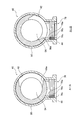
- FIG. 9 is a cross-sectional view taken along the line AA in FIG.
- the diagram on the left side of FIG. 9 is a diagram showing a state in which the main communication hole 44 and the main opening 56a of the valve body 50 are not in communication.
- the diagram on the right side of FIG. 9 is a diagram showing a state where the main communication hole 44 and the main opening 56a communicate with each other.
- the seal member 76 will be described with reference to FIGS.
- a seal member 76 is provided inside the main communication hole 44.
- the seal member 76 includes a seal body portion 76a, a spring 76b, and a retainer 76c.
- the seal body 76a is formed in a cylindrical shape.
- the tip of the seal main body 76a abuts on the outer peripheral surface of the spherical body 52 of the valve body 50.
- the tip of the seal body 76a is formed in a spherical shape along the shape of the outer peripheral surface of the sphere 52.
- the spring 76b is contracted between the seal body 76a and the retainer 76c.
- the spring 76b biases the seal body 76a toward the valve body 50.
- the retainer 76c is fixed to the main communication hole 44 by screwing into the main communication hole 44, for example. Cooling water tends to flow into the main communication hole 44 from the engine 1 to the mechanical control valve 4 side. Therefore, a force for pressing the seal main body 76a against the outer peripheral surface of the valve body 50 by the cooling water acts, and the sealing performance can be improved.
- a minute gap is provided between the inner peripheral surface 42 around the opening of the second sub-communication hole 45 to the valve body accommodating portion 43 and the outer peripheral surface of the valve body 50. This gap constitutes a seal portion 78.
- a minute gap is provided between the inner peripheral surface 42 around the opening of the third sub-communication hole 46 to the valve body accommodating portion 43 and the outer peripheral surface of the valve body 50. This gap constitutes a seal portion 79.
- the second sub-communication hole 45 and the opening 56c of the valve body 50 and the third sub-communication hole 46 and the opening 56d are not communicated with each other, the second sub-communication is passed through the seal portions 78 and 79. Cooling water may leak into the hole 45 and the third sub communication hole 46.
- the leakage amount of the cooling water is managed by the pressure loss given to the cooling water by the seal portions 78 and 79.
- the pressure loss is adjusted by the length of the seal portions 78 and 79 (gap) in the axial direction of the housing 40 (the direction of the rotation axis of the valve body 50).
- the pressure loss is set by a decrease in the rate of temperature increase due to cooling water leakage allowed on the engine 1 side.
- the pressure loss given to the cooling water by the seal part 79 is made larger than the pressure loss given to the cooling water by the seal part 78.
- FIG. 10 is a view showing an operating state of the mechanical control valve 4.
- the left side is a cross-sectional view showing each operation state of the mechanical control valve 4.
- the right side is a schematic diagram showing a communication state of the main communication hole 44 and the sub communication holes 45, 46, 48 and the openings 56a to 56d.
- the first stage shows a diagram when the mechanical control valve 4 is fully closed.
- the second stage shows a diagram when the mechanical control valve 4 is in the first valve open state.
- the third stage shows a diagram when the mechanical control valve 4 is in the second open state.
- the fourth row shows a diagram when the mechanical control valve 4 is fully opened.
- some reference numerals are omitted.
- the main communication hole 44 and each sub communication hole 45, 46, 48 are hatched. What is shown indicates a state in which the openings 56a to 56d are not in communication. Further, in the same figure, the main communication hole 44 and the sub communication holes 45, 46 and 48 shown in black indicate the state where they communicate with the openings 56a to 56d.
- the first sub communication hole 48 communicates with the first sub opening 56b in any state of the mechanical control valve 4.
- the mechanical control valve 4 is in the fully closed state, as shown in the first stage of FIG. 10, the main communication hole 44 and the main opening 56a, the second sub communication hole 45 and the opening 56c, and the third sub communication hole 46
- the opening 56d is not in communication.
- the cooling water flowing in from the engine 1 is blocked by the outer peripheral surface of the valve body 50 and the seal member 76 in the main communication hole 44 and does not flow out to the cabin heater 5, the oil cooler 6, and the radiator 7.
- the mechanical control valve 4 is in the first valve open state, as shown in the second stage of FIG.
- the main communication hole 44 and the main opening 56a communicate with each other, but the second sub communication hole 45 and the opening 56c
- the third auxiliary communication hole 46 and the opening 56d are not in communication.
- the cooling water flowing in from the engine 1 flows into the fluid inflow portion 54 of the valve body 50 through the main communication hole 44, and flows out from the first sub communication hole 48 to the cabin heater 5. At this time, a part of the cooling water flowing into the fluid inflow portion 54 leaks into the second sub communication hole 45 and the third sub communication hole 46, but the amount of the cooling water flows out from the first sub communication hole 48. Very little compared to
- the main communication hole 44 and the main opening 56a and the second sub communication hole 45 and the opening 56c communicate with each other as shown in the third stage of FIG.
- the third auxiliary communication hole 46 and the opening 56d are not in communication.
- the cooling water flowing from the engine 1 flows into the fluid inflow portion 54 of the valve body 50 through the main communication hole 44, and flows out from the first sub communication hole 48 to the cabin heater 5 and from the second sub communication hole 45 to the oil cooler 6. To do. At this time, a part of the cooling water flowing into the fluid inflow portion 54 leaks into the third sub communication hole 46, but the amount of the cooling water flows out from the first sub communication hole 48 and the second sub communication hole 45.
- the main communication hole 44 and the main opening 56a, the second sub communication hole 45 and the opening 56c, and the third sub communication hole 46 communicates with the opening 56d.
- the cooling water flowing from the engine 1 flows into the fluid inflow portion 54 of the valve body 50 through the main communication hole 44, from the first sub communication hole 48 to the cabin heater 5, and from the second sub communication hole 45 to the oil cooler 6, It flows out from the third sub-communication hole 46 to the radiator 7.
- seal portions 78 and 79 are provided between the second sub-communication hole 45, the third sub-communication hole 46, and the valve body 50 to provide a pressure loss to the cooling water.
- the number of seal members in contact with the valve body 50 can be reduced, and friction when the valve body 50 is rotated can be reduced. Therefore, the drive mechanism 60 can be downsized.
- the mechanical control valve 4 is controlled to be fully closed. The mechanical control valve 4 prevents the cooling water from flowing from the engine 1 to the cabin heater 5, the oil cooler 6, and the radiator 7 so as to suppress the temperature drop of the cooling water.
- a seal member 76 is provided between the main communication hole 44 and the valve body 50 so as to minimize the leakage of cooling water from between the main communication hole 44 and the valve body 50.
- the mechanical control valve 4 When the temperature of the engine 1 rises to some extent (for example, the cooling water temperature is about 60 ° C.), the mechanical control valve 4 is brought into the first valve open state. At this time, the cooling water flows out from the engine 1 to the cabin heater 5 by the mechanical control valve 4. In the cabin heater 5, heat is exchanged between the air in the passenger compartment and the cooling water to heat the passenger compartment. At this time, even if a small amount of cooling water leaks from between the second sub-communication hole 45 or the third sub-communication hole 46 and the valve body 50, the cooling water has already flowed out to the first sub-communication hole 48 side. Therefore, the leakage of the cooling water does not greatly affect the temperature rise of the engine 1.
- some extent for example, the cooling water temperature is about 60 ° C.
- seal portions 78 and 79 formed by a gap between the inner peripheral surface 42 of the housing 40 and the outer peripheral surface of the valve body 50 are provided between the second sub communication hole 45 and the third sub communication hole 46.
- the seal portions 78 and 79 allow cooling water to leak.
- the pressure of the cooling water in the fluid inflow portion 54 is not large, and the cooling water leaks from the seal portions 78 and 79. The amount can be kept small.
- the pressure loss applied to the cooling water in the seal portions 78 and 79 is set by the length of the gap constituting the seal portions 78 and 79 in the direction of the rotation axis of the valve body 50.
- the pressure loss given to the cooling water in the seal portions 78 and 79 is set by a decrease in the temperature increase rate allowed on the engine 1 side due to the leakage of the cooling water.
- the pressure loss can be easily set by the length of the gap constituting the seal portions 78 and 79.
- the gap corresponding to the seal portions 78 and 79 is not provided between the first sub communication hole 48 and the valve body 50.
- the first sub communication hole 48 is always in communication with the first sub opening 56b, and there is no need to provide a seal between the first sub communication hole 48 and the valve body 50.
- the cooling water can flow out from the first sub-communication hole 48 without unnecessarily causing pressure loss to the cooling water.
- the first sub communication hole 48 is connected to the cabin heater 5. When the temperature of the engine 1 rises to some extent, the cabin heater 5 is connected to the first sub-communication hole 48 that communicates with the main communication hole 44 first, so that the vehicle interior can be heated early.
- Example 1 when the mechanical control valve 4 is in the first valve open state, the main communication hole 44 and the second sub communication hole 45 communicate with each other via the seal portion 78, and the main communication hole 44 and the third communication hole 44 communicate with each other.
- the sub-communication hole 46 communicates with the seal part 79.
- the cooling water from the main communication hole 44 toward the second sub communication hole 45 and the third sub communication hole 46 is subjected to pressure loss by the seal portions 78 and 79. Therefore, the cooling water hardly leaks into the second sub communication hole 45 and the third sub communication hole 46, and the temperature drop of the cooling water can be suppressed.
- the oil cooler 6 is connected to the second auxiliary communication hole 45 and the radiator 7 is connected to the third auxiliary communication hole 46.
- the oil cooler 6 is connected to the second sub communication hole 45 where the cooling water hardly leaks, and the radiator 7 is connected to the third sub communication hole 46.
- the pressure loss given to the cooling water by the seal portion 79 is made larger than the pressure loss given to the cooling water by the seal portion 78.
- the amount of cooling water flowing out to the radiator 7 can be made smaller than the amount of cooling water flowing out to the oil cooler 6.
- the amount of cooling water flowing out to the radiator 7 having high cooling water cooling performance can be reduced, and the temperature drop of the cooling water can be suppressed.
- the main communication hole 44 is provided substantially at the center with respect to the axial direction of the housing 40. Thereby, the respective distances from the main communication hole 44 to the first sub communication hole 48, the second sub communication hole 45, and the third sub communication hole 46 can be made substantially equal. Cooling water to 45, 46 and 48 can be supplied almost evenly.
- the second sub communication hole 45 is provided on the opposite side of the third sub communication hole 46 with the main communication hole 44 in the axial direction of the housing 40. Thereby, the respective distances from the main communication hole 44 to the first sub communication hole 48, the second sub communication hole 45, and the third sub communication hole 46 can be made substantially equal. Cooling water to 45, 46 and 48 can be supplied almost evenly.
- the drive shaft 63 is supported by the first bearing 70 and the second bearing 73 from both axial ends of the insertion hole 41a of the bottom 41 of the housing 40. As a result, the drive shaft 63 can be stably supported.
- Example 1 The effects of Example 1 are listed below.
- the valve body housing portion 43 formed in a hollow shape, the main communication hole 44 through which the valve body housing portion 43 communicates with the outside, and the fluid that communicates between the valve body housing portion 43 and the outside.
- a housing 40 having a first sub-communication hole 48 that circulates, a second sub-communication hole 45 that communicates between the valve body housing portion 43 and the outside, and a fluid inflow portion 54 that is formed in a hollow shape.
- a valve body 50 having a plurality of openings 56 communicating with the fluid inflow portion 54 and the outside, and disposed rotatably in the valve body housing portion 43, and a drive mechanism 60 that rotationally drives the valve body 50;
- a seal member 76 that is provided between the main communication hole 44 and the valve body 50 and seals between the housing 40 and the valve body 50.
- the valve body 50 is a first sub communication hole regardless of the rotational position. 48 and the first sub opening 56b are always in communication with each other, and the communication state between the main communication hole 44, the main opening 56a, the second sub communication hole 45, and the second sub opening 56c is changed according to the rotational position.
- valve body 50 The cooling water (fluid) leaking from the peripheral surface to the second sub communication hole 45 is given a pressure loss by a gap formed between the valve body housing portion 43 and the valve body 50, and the pressure loss is the main communication hole. 44 and the main opening 56a communicate with each other, and the second sub communication hole 45 and the opening 56c do not communicate with each other, the amount of fluid leaking into the second sub communication hole 45 is the amount of the main communication hole 44. Is set according to the amount allowed in the connected engine 1 (device). As a result, the number of seal members in contact with the valve body 50 can be reduced, and friction when the valve body 50 is rotated can be reduced. Therefore, the drive mechanism 60 can be downsized.
- the pressure loss is caused by the valve body 50 out of the lengths of the seal portions 78 and 78 (gap portions) formed between the inner peripheral surface 42 of the valve body housing portion 43 and the outer peripheral surface of the valve body 50. It was set according to the length of the part extending in the direction of the rotation axis. Thereby, the pressure loss can be easily set.
- the main communication hole 44 and the main opening 56a communicate with each other, the main communication hole 44 and the first sub communication hole 48 are the inner peripheral surface of the valve body housing portion 43 and the outer peripheral surface of the valve body 50. It was made to communicate without passing through the seal part (gap part) formed between. As a result, the cooling water can flow out from the first sub-communication hole 48 without unnecessarily causing pressure loss to the cooling water.
- the first sub-communication hole 48 is connected to the cabin heater 5 (heating heat exchanger) used for heating the passenger compartment. Thereby, heating of a vehicle interior can be performed at an early stage.
- the main communication hole 44 communicates with the main opening 56a and the second sub communication hole 45 does not communicate with the second sub opening 56c, the main communication hole 44 and the second sub communication The holes 45 communicate with each other via a seal portion 78 (gap portion) formed between the inner peripheral surface 42 of the valve body housing portion 43 and the outer peripheral surface of the valve body 50.
- the housing 40 has a third sub-communication hole 46 that allows the fluid to communicate with the valve body accommodating portion 43 and the outside, and the valve body 50 is open to the third sub-communication hole 46 according to the rotational position.
- the main communication hole 44 and the first sub communication hole 48 are connected to the inner peripheral surface 42 of the valve body housing portion 43.
- the main communication hole 44 communicates with the main opening 56a, and the second sub communication hole 45
- the main communication hole 44 and the second sub communication hole 45 are formed between the inner peripheral surface 42 of the valve body housing portion 43 and the outer peripheral surface of the valve body 50.
- the hole 44 and the third sub-communication hole 46 are formed on the inner peripheral surface 42 of the valve body housing portion 43 and With respect to the pressure loss of the seal part 78 (gap part) between the main communication hole 44 and the second sub-communication hole 45, it communicates via the seal part 79 (gap part) formed between the surfaces.
- the pressure loss of the seal part 79 (gap part) between the main communication hole 44 and the third sub communication hole 46 was made large. Thereby, when the mechanical control valve 4 is in the first valve open state, the cooling water hardly flows out to the oil cooler 6 and the radiator 7 having a high cooling performance, so that the temperature drop of the cooling water can be suppressed.
- the second sub-communication hole 45 is connected to the oil cooler 6 that cools the engine oil that lubricates the inside of the engine 1, and the third sub-communication hole 46 is connected to the radiator 7 that cools the fluid. did.
- the amount of cooling water flowing out to the radiator 7 can be made smaller than the amount of cooling water flowing out to the oil cooler 6.
- the amount of cooling water flowing out to the radiator 7 having high cooling water cooling performance can be reduced, and the temperature drop of the cooling water can be suppressed.
- the main communication hole 44 is provided in the axial center of the housing 40 in the direction of the rotation axis of the valve body 50. Thereby, the respective distances from the main communication hole 44 to the second sub communication hole 45 and the third sub communication hole 46 can be made substantially equal, and from the main communication hole 44 to the sub communication holes 45, 46, 48. Cooling water can be supplied almost evenly.
- the housing 40 has a third sub-communication hole 46 that communicates the valve body accommodating portion 43 with the outside and communicates the fluid, and the second sub-communication hole 45 is formed in the direction of the rotation axis of the valve body 50 Provided on the opposite side of the third sub-communication hole 46 across the communication hole 44.
- the respective distances from the main communication hole 44 to the second sub communication hole 45 and the third sub communication hole 46 can be made substantially equal, and from the main communication hole 44 to the sub communication holes 45, 46, 48. Cooling water can be supplied almost evenly.
- the drive mechanism 60 includes a drive shaft 63 that rotates integrally with the valve body 50, an insertion hole 41a that passes through the bottom 41 of the valve body housing portion 43, and the drive shaft 63 is inserted, and a shaft of the insertion hole 41a.
- a first bearing 70 and a second bearing 73 (support member) that rotatably support the drive shaft 63 are provided at both ends in the direction. As a result, the drive shaft 63 can be stably supported.
- valve body housing portion 43 formed in a hollow shape, the main communication hole 44 through which the valve body housing portion 43 communicates with the outside, the fluid for cooling the engine 1 (heat source) flows, and the main communication hole 44
- a housing 40 having a plurality of sub-communication holes 45 and 48 for distributing the inflowing fluid to the heat exchanger, a fluid inflow portion 54 formed in a hollow shape, and a plurality of fluid inflow portions 54 and the outside communicate with each other
- a valve body 50 having an opening 56 and rotatably disposed in the valve body housing part 43; provided between the main communication hole 44 and the valve body 50; and abutting on an outer peripheral surface of the valve body 50
- a seal member 76 contact seal member that seals between the valve body 50 and the housing 40, and the valve body 50 has an opening and a main communication hole 44 and sub-communication holes 45 and 48 according to the rotational position.
- the sub communication holes 45 and 48 communicate with the first sub communication hole 48 that is always in communication with the first sub opening 56b and the opening 56c according to the rotational position of the valve body 50.
- Radiator 7 that cools the inflowing fluid, and the cooling water (fluid) that is provided via the radiator 7 (heat exchanger) and cooled in the radiator 7 (heat exchanger) It has a circuit for cooling the heat source by circulating, and a mechanical control valve 4 (flow control valve) that controls the flow rate of the cooling water (fluid) circulating in the circuit, and mechanical control valve 4 (flow control valve) ) Includes a hollow valve body housing portion 43, a main communication hole 44 that is connected to a heat source and communicates between the valve body housing portion 43 and the outside, and the valve body housing portion 43 and the outside.
- a housing 40 having a first sub-communication hole 48 through which a communication fluid flows, a second sub-communication hole 45 through which the fluid flows through the valve body housing portion 43 and the outside, and a fluid formed in a hollow shape
- a valve body 50 rotatably disposed in the valve body housing portion 43, a drive mechanism 60 that rotationally drives the valve body 50, a main communication hole 44, and the valve body 50.
- a seal member 76 that seals between the valve body 50, and the valve body 50 always communicates the first sub-communication hole 48 and the first sub-opening 56b regardless of the rotation position, and at the rotation position.
- the communication state of the main communication hole 44 and the second sub communication hole 45 and the openings 56a and 56c is changed, and the cooling water (fluid) leaking from the outer peripheral surface of the valve body 50 to the second sub communication hole 45 is Pressure loss is given by a gap formed between the valve body housing portion 43 and the valve body 50, the pressure loss is communicated between the main communication hole 44 and the main opening 56a, and the second sub communication hole 45 And the opening 56c are not in communication with each other, the amount of fluid leaking into the second sub-communication hole 45 is set according to the amount allowed in the device to which the main communication hole 44 is connected. I made it. As a result, the number of seal members in contact with the valve body 50 can be reduced, and friction when the valve body 50 is rotated can be reduced. Therefore, the drive mechanism 60 can be downsized.
- the circuit is connected to the engine 1 (internal combustion engine), which is a heat source, and supplies cooling water (fluid) pumped by a pump 2 disposed on the side where fluid is supplied to the engine 1 (internal combustion engine).
- the internal communication hole 44 is connected to the discharge side of the pump 2 in the circuit, formed as a cooling circuit for the engine 1 (internal combustion engine) for cooling the engine 1 (internal combustion engine) by circulating inside. It was made to be. Accordingly, the present invention can be applied to a type of system in which the mechanical control valve 4 is disposed on the discharge side of the pump 2.
- Example 2 In Example 2, the outer diameter of the valve body 50 was changed. In Example 2, a part of the structure of the seal portion 78 was changed.
- FIG. 11 is a sectional view of the mechanical control valve 4 (fully closed state).
- FIG. 12 is a cross-sectional view of the mechanical control valve 4 (fully opened state).
- the outer peripheral surface of the valve body 50 includes a large diameter part 51 and a small diameter part 53.
- a step portion 57 having a surface extending in the radial direction of the valve body 50 from the small diameter portion 53 toward the large diameter portion 51 is formed.
- a step portion 42e formed along the shape of the step portion 57 of the valve body 50 is provided in the vicinity of the portion of the inner peripheral surface 42 of the housing 40 where the second sub communication hole 45 opens.
- the seal portion 78 provided between the second sub-communication hole 45 and the valve body 50 is formed by a gap between the step portion 57 of the valve body 50 and the step portion 42e of the housing 40.
- the pressure loss applied to the cooling water in the seal portion 78 is adjusted by the length of the seal portion 78 (gap) in the radial direction of the housing 40 (in the radial direction with respect to the rotation axis of the valve body 50).
- the pressure loss is the rotational axis of the valve body 50 out of the length of the seal part 78 (gap part) formed between the inner peripheral surface 42 of the valve body housing part 43 and the outer peripheral surface of the valve body 50.
- the length of the portion extending in the radial direction is set. Thereby, the pressure loss can be easily set.
- Example 3 In Example 2, the structure of a part of the seal portion 78 was changed.
- the configuration of the mechanical control valve 4 of the third embodiment will be described, but the same components as those of the first embodiment are denoted by the same reference numerals and description thereof will be omitted.
- FIG. 13 is a cross-sectional view of the vicinity of the second sub-communication hole 45.
- a part of the seal portion 78 is formed so that a gap formed between the inner peripheral surface 42 of the valve body housing portion 43 and the outer peripheral surface of the valve body 50 is in the direction of the rotation axis of the valve body 50.
- the labyrinth seal was formed by combining an extending portion and a portion extending in the radial direction with respect to the rotation axis.
- Example 4 In Example 2, the structures of the second sub communication hole 45 and the third sub communication hole 46 were changed.
- FIG. 14 is a cross-sectional view of the mechanical control valve 4 (fully closed state).
- FIG. 15 is a cross-sectional view of the mechanical control valve 4 (fully opened state).
- a second sub communication hole 45 is provided on the outer peripheral surface of the housing 40.
- the second sub communication hole 45 is formed to extend in the radial direction of the housing 40.
- a third sub-communication hole 46 is provided on the outer peripheral surface of the housing 40 and adjacent to the second sub-communication hole 45.
- the third auxiliary communication hole 46 is formed to extend in the radial direction of the housing 40.
- the main communication hole 44 and the third sub communication hole 46 are arranged on the same straight line.
- the second sub-communication hole 45 and the third sub-communication hole 46 are provided so as to extend in the radial direction from the outer peripheral surface of the housing 40 to the rotation axis of the valve body 50.
- Example 5 In the fifth embodiment, the configuration of the speed reducer 62 of the drive mechanism 60 is changed.
- the speed reducer 62 includes a first gear 62e, a second gear 62f, and a third gear 62g.
- the first gear 62e, the second gear 62f, and the third gear 62g are all spur gears.
- the first gear 62e is provided so as to rotate integrally with the output shaft of the motor 61.
- the first gear 62e meshes with the second gear 62f.
- the second gear 62f meshes with the third gear 62g.
- the third gear 62g is provided at the tip of the drive shaft 63 so as to rotate integrally with the drive shaft 63.
- the drive mechanism 60 decelerates the output of the motor 61 by the spur gear set and transmits it to the valve body 50 as a rotational drive force.
- the reduction gear 62 can be comprised by a spur gear set, and the reduction gear 62 can be manufactured cheaply. Therefore, the present invention can be applied to a system in which the mechanical control valve 4 is disposed on the discharge side of the pump 2.
- FIG. 17 is a schematic diagram showing a configuration of a circulation circuit of cooling water for cooling the engine 1. Cooling water is pumped to the engine 1 by the pump 2. Cooling water that has cooled the engine 1 is distributed to the electronically controlled throttle body 3, the cabin heater 5, the oil cooler 6, and the radiator 7. The cooling water flowing into the electronically controlled throttle body 3 is returned to the suction side of the pump 2. Cooling water that has flowed into the cabin heater 5, the oil cooler 6, and the radiator 7 is sent to the mechanical control valve 4.
- the mechanical control valve 4 is in a fully closed state in which the cooling water flowing out from the cabin heater 5, the oil cooler 6, and the radiator 7 is not returned to the suction side of the pump 2, and the cooling water flowing out from the cabin heater 5 is sucked into the pump 2.
- the fully open state in which the cooling water that has flowed out of the radiator 7 is returned to the suction side of the pump 2 is switched.
- the circuit is connected to the engine 1 (internal combustion engine), which is a heat source, and supplies cooling water (fluid) pumped by a pump 2 disposed on the side where fluid is supplied to the engine 1 (internal combustion engine).
- the engine 1 internal combustion engine
- It is formed as a cooling circuit for the engine 1 (internal combustion engine) for cooling the engine 1 (internal combustion engine) by circulating inside, and the main communication hole 44 is connected to the suction side of the pump 2 in the circuit It was made to be. Accordingly, the present invention can be applied to a type of system in which the mechanical control valve 4 is disposed on the suction side of the pump 2.
- the present invention has been described based on the first to fifth embodiments.
- the specific configuration of each invention is not limited to the first to fifth embodiments and does not depart from the gist of the present invention.
- Such design changes are included in the present invention.
- any combination or omission of each constituent element described in the claims and the specification is possible within a range where at least a part of the above-described problems can be solved or a range where at least a part of the effect is achieved. It is.
- the engine 1 that is a heat source is cooled by cooling water.
- the present invention is not limited to the engine 1, and may be applied to, for example, a vehicle driving motor or an inverter that cools the inverter.
- the valve body 50 has the spherical body portion 52. As shown in FIG. 18, this configuration may use a valve body 50 that is formed in a cylindrical shape in the same manner as the valve body 50 of the second embodiment.
- the seal member 76 that contacts the valve body 50 is provided only between the main communication hole 44 and the valve body 50.
- a seal member 80 that contacts the valve body 50 may also be provided between the third auxiliary communication hole 46 and the valve body 50. It is possible to suppress leakage of the cooling water to the radiator 7 having a high cooling performance. In this case, since the valve body 50 can be supported by the two seal members 76 and 80, the slide bearing 75 may be eliminated.
- the fluid control valve in one embodiment thereof, A hollow valve body housing portion, a main communication hole through which the valve body housing portion communicates with the outside, and a first auxiliary passage through which fluid flows through the valve body housing portion and the outside.
- a housing having a communication hole, and a second sub communication hole through which fluid flows through the valve body housing portion and the outside;
- a valve body having a fluid inflow portion formed in a hollow shape and a plurality of openings communicating the fluid inflow portion and the outside, and rotatably disposed in the valve body housing portion;
- a seal member provided between the main communication hole and the valve body and sealing between the housing and the valve body; The valve body always communicates the first sub-communication hole and the opening regardless of the rotational position, and communicates the main communication hole, the second sub-communication hole, and the opening according to the rotational position.
- the fluid leaking from the outer peripheral surface of the valve body to the second sub-communication hole is given a pressure loss by a gap formed between the valve body housing portion and the valve body,
- the pressure loss is such that fluid leaks into the second sub-communication hole in a state where the main communication hole and the opening communicate with each other and the second sub-communication hole does not communicate with the opening.
- the amount is set according to the amount allowed in the device to which the main communication hole is connected. Thereby, the number of the sealing members which contact a valve body can be reduced, and the friction at the time of rotating a valve body can be reduced. Therefore, the drive mechanism can be reduced in size.
- the pressure loss is caused by rotation of the valve body out of a length of a gap formed between an inner peripheral surface of the valve body housing portion and an outer peripheral surface of the valve body. It is set by the length of the portion extending in the radial direction with respect to the axis. Thereby, the pressure loss can be easily set.
- the pressure loss is the length of the portion extending in the direction of the rotation axis of the valve body, out of the length of the gap formed between the inner circumferential surface of the valve body housing portion and the outer circumferential surface of the valve body. Set by Thereby, the pressure loss can be easily set.
- the pressure loss is such that the gap formed between the inner peripheral surface of the valve body housing portion and the outer peripheral surface of the valve body has a diameter with respect to a portion extending in the direction of the rotary shaft of the valve body and the rotary shaft. This is caused by forming a labyrinth seal combined with a portion extending in the direction. Thereby, the pressure loss can be easily set.
- the main communication hole communicates with the opening
- the main communication hole and the first sub communication hole are formed between an inner peripheral surface of the valve body housing portion and an outer peripheral surface of the valve body. Communicate without going through the gap.
- the cooling water can be allowed to flow out of the first sub-communication hole without unnecessarily causing pressure loss to the cooling water.
- the first sub-communication hole is connected to a heating heat exchanger used for heating the passenger compartment. Thereby, heating of a vehicle interior can be performed at an early stage.
- the main communication hole and the opening are in communication, and the second sub communication hole and the opening are not in communication
- the main communication hole and the second sub communication hole are the valve It communicates via the clearance gap formed between the internal peripheral surface of a body accommodating part, and the outer peripheral surface of the said valve body.
- the fluid cools the engine
- the second sub-communication hole is a flow control valve connected to an oil cooler that cools engine oil that lubricates the inside of the engine or a radiator that cools the fluid.
- the housing has a third sub-communication hole that allows fluid to communicate between the valve body housing portion and the outside,
- the valve body changes a communication state between the third sub communication hole and the opening according to a rotation position,
- the main communication hole and the first sub communication hole are formed between an inner peripheral surface of the valve body housing portion and an outer peripheral surface of the valve body.
- the main communication hole and the second sub communication hole are the valve Communicating through a gap formed between the inner peripheral surface of the body housing portion and the outer peripheral surface of the valve body
- the main communication hole and the third sub communication hole are the valve Communicating through a gap formed between the inner peripheral surface of the body housing portion and the outer peripheral surface of the valve body
- the pressure loss in the gap portion between the main communication hole and the third sub communication hole is larger than the pressure loss in the gap portion between the main communication hole and the second sub communication hole.
- An oil cooler for cooling engine oil that lubricates the inside of the engine is connected to the second sub communication hole,
- the third sub-communication hole is connected to a radiator that cools the fluid.
- the main communication hole is provided at the axial center of the housing in the direction of the rotation axis of the valve body.
- the housing has a third sub-communication hole that allows fluid to communicate between the valve body housing portion and the outside,
- the second sub communication hole is provided on the opposite side of the third sub communication hole with respect to the main communication hole in the direction of the rotation axis of the valve body.
- the second sub-communication hole and the third sub-communication hole are provided so as to extend radially from the outer peripheral surface of the housing with respect to the rotation axis of the valve body. The appearance of the flow control valve can be changed according to the piping arrangement.
- the drive mechanism includes a drive shaft that rotates integrally with the valve body, an insertion hole that passes through a bottom portion of the valve body housing portion, and into which the drive shaft is inserted, at both axial ends of the insertion hole, And a support member that rotatably supports the drive shaft.
- a drive shaft can be supported stably.
- the drive mechanism decelerates the output of the motor with a spur gear set and transmits it to the valve body as a rotational drive force. Thereby, a drive mechanism can be manufactured cheaply.
- the cooling system A valve body housing portion formed in a hollow shape, a main communication hole through which the valve body housing portion communicates with the outside and into which a fluid for cooling a heat source flows, and a fluid that flows in from the main communication hole is distributed to a heat exchanger A plurality of sub-communication holes, and a housing having A valve body having a fluid inflow portion formed in a hollow shape and a plurality of openings communicating the fluid inflow portion and the outside, and rotatably disposed in the valve body housing portion; A contact seal member that is provided between the main communication hole and the valve body and seals between the valve body and the housing by contacting an outer peripheral surface of the valve body; The valve body changes a communication state between the main communication hole and the sub communication hole and the opening according to a rotation position,
- the sub-communication hole is a first sub-communication hole that is always in communication with the opening, and a second sub-communication hole that is switched between a state that communicates with the opening and a state that does not communicate according to the rotation
- the second sub-communication hole is configured so that the main communication hole and the opening communicate with each other, and the second sub-communication hole and the opening do not communicate with each other.
- the fluid can flow through a non-contact seal formed between the surface and the outer peripheral surface of the valve body.
- the cooling system A heat exchanger for cooling the inflowing fluid; A circuit which is provided so as to pass through the heat exchanger and which serves to cool a heat source by circulating a fluid cooled in the heat exchanger; A flow rate control valve for controlling the flow rate of the fluid circulating in the circuit,
- the flow control valve is A valve body housing portion formed in a hollow shape, a main communication hole that is connected to the heat source and communicates between the valve body housing portion and the outside, and a fluid that communicates the valve body housing portion and the outside.
- a housing having a first sub-communication hole that circulates, and a second sub-communication hole that allows the fluid to circulate through the valve body housing portion and the outside;
- a valve body having a fluid inflow portion formed in a hollow shape and a plurality of openings communicating the fluid inflow portion and the outside, and rotatably disposed in the valve body housing portion;
- a seal member provided between the main communication hole and the valve body and sealing between the housing and the valve body; The valve body always communicates the first sub-communication hole and the opening regardless of the rotational position, and communicates the main communication hole, the second sub-communication hole, and the opening according to the rotational position.
- the fluid leaking from the outer peripheral surface of the valve body to the second sub-communication hole is given a pressure loss by a gap formed between the valve body housing portion and the valve body,
- the pressure loss is such that fluid leaks into the second sub-communication hole in a state where the main communication hole and the opening communicate with each other and the second sub-communication hole does not communicate with the opening.
- the amount is set according to the amount allowed in the device to which the main communication hole is connected. Thereby, the number of the sealing members which contact a valve body can be reduced, and the friction at the time of rotating a valve body can be reduced. Therefore, the drive mechanism can be reduced in size.
- the circuit is connected to an internal combustion engine that is the heat source, and causes the fluid that is pumped by a pump disposed on the side to which the fluid is supplied to the internal combustion engine to flow inside the internal combustion engine, thereby causing the internal combustion engine to circulate.
- a cooling circuit for an internal combustion engine for cooling The main communication hole is connected to the discharge side of the pump in the circuit.
- the circuit is connected to an internal combustion engine that is the heat source, and causes the fluid that is pumped by a pump disposed on the side to which the fluid is supplied to the internal combustion engine to flow inside the internal combustion engine, thereby causing the internal combustion engine to circulate.
- a cooling circuit for an internal combustion engine for cooling The main communication hole is a cooling system connected to the suction side of the pump in the circuit.
Landscapes
- Engineering & Computer Science (AREA)
- General Engineering & Computer Science (AREA)
- Mechanical Engineering (AREA)
- Chemical & Material Sciences (AREA)
- Combustion & Propulsion (AREA)
- Multiple-Way Valves (AREA)
- Taps Or Cocks (AREA)
- Valve Housings (AREA)
- Air-Conditioning For Vehicles (AREA)
Abstract
ハウジング内の弁体を回転駆動させる際のトルクを低減することができる流量制御弁を提供すること。 流量制御弁は、主連通孔または主開口部から隙間部への流体の漏れを抑制するシール部材を備え、駆動機構に回転駆動される弁体は、弁体の回転位置に関わらず第1副連通孔と第1副開口部とを連通させるとともに、弁体の回転位置に応じて、主連通孔と主開口部の連通状態と、第2副連通孔と第2副開口部との連通状態と、を変化させる。弁体収容部の内周面と弁体周壁の外周面との間に形成される隙間部を介して第2副連通孔に漏れ出す流体は、隙間部によって圧力損失が与えられ、主連通孔と主開口部とが連通し、かつ、第2副連通孔と第2副開口部とが連通していない状態において、第2副連通孔に流体が漏れ出す量が、主連通孔に接続させる装置において許容される量に応じて設定されるようにした。
Description
本発明は、流量制御弁および冷却システムに関する。
この種の技術としては、下記の特許文献1に記載の技術が開示されている。特許文献1には、弁ハウジング内に回動可能に設けられた弁体を有する流量制御弁が開示されている。弁ハウジングにはエンジンからの温水が流量制御弁内に流入する温水入口パイプと、流入した温水を熱交換器に向けて流出させる温水出口パイプが一体に形成されている。温水入口ポイプと弁体との間、および、温水出口パイプと弁体との間には、ゴム等の弾性材からなるシール部材が設けられている。
上記特許文献1の技術にあっては、シール部材が温水入口ポイプと弁体との間、および、温水出口パイプと弁体との間に設けられており、弁体とシール部材との間の摺動抵抗が大きくなる。そのため、弁体を回転させる際の回転トルクが過大となるおそれがあった。
本発明は、その目的とするところは、ハウジング内の弁体を回転駆動させる際のトルクを低減することができる流量制御弁および冷却システムを提供することである。
本発明は、その目的とするところは、ハウジング内の弁体を回転駆動させる際のトルクを低減することができる流量制御弁および冷却システムを提供することである。
上記目的を達成するため、本発明の第1の実施形態では、流量制御弁は、主連通孔と弁体との間に設けられ、主連通孔または主開口部から隙間部への流体の漏れを抑制するシール部材を備え、駆動機構によって回転駆動される弁体は、弁体の回転位置に関わらず第1副連通孔と第1副開口部とを連通するとともに、弁体の回転位置に応じて主連通孔と主開口部の連通状態と、第2副連通孔と第2副開口部との連通状態を変化させ、弁体収容部の内周面と弁体周壁の外周面との間で形成される隙間部を介して第2副連通孔に漏れ出す流体は、隙間部によって圧力損失が与えられ、主連通孔と主開口部とが連通し、かつ、第2副連通孔と第2副開口部とが連通していない状態において、第2副連通孔に流体が漏れ出す量が、主連通孔が接続する装置において許容される量に応じて設定されるようにした。
第2の実施形態では、流量制御弁は、ハウジングと弁体との間に設けられ、弁体の外周面に当接することで弁体とハウジングとの間をシールする接触シール部材を備え、弁体は、回転位置に応じて主連通孔と主開口部の連通状態と、副連通孔と複数の副開口部との連通状態が変化し、副連通孔は、第1副開口部と常時連通する第1副連通孔と、弁体の回転位置に応じて第2副開口部と連通する状態と連通しない状態とが切り替えられる第2副連通孔と、を有し、第2副連通孔は、主連通孔と主開口部とが連通し、かつ、第2副連通孔と第2副開口部とが連通していない状態において、弁体収容部の内周面と弁体周壁の外周面との間に形成される非接触シールを介して、流体が流通可能であるようにした。
第3の実施形態では、冷却システムは、流入した流体を冷却する熱交換器と、熱交換器を経由するように設けられ、熱交換器において冷却された流体を循環させることで熱源の冷却に供する回路と、回路内を循環する流体の流量を制御する流量制御弁と、を有し、流量制御弁は、ハウジングと弁体との間に設けられ、主連通孔または主開口部から隙間部への漏れを抑制するシール部材を備え、駆動機構によって回転駆動される弁体は、弁体の回転位置に関わらず第1副連通孔と第1副開口部とを連通するとともに、弁体の回転位置に応じて主連通孔と主開口部との連通状態と、第2副連通孔と第2副開口部との連通状態と、を変化させ、弁体収容部の内周面と弁体周壁の外周面との間で形成される隙間部を介して第2副連通孔に漏れ出す流体は、隙間部によって圧力損失が与えられ、主連通孔と主開口部とが連通し、かつ、第2副連通孔と第2副開口部とが連通していない状態において、第2副連通孔に流体が漏れ出す量は、主連通孔が接続する装置において許容される量に応じて設定されるようにした。
よって、弁体に接触するシール部材の数を減らすことができ、弁体を回転させる際のフリクションを低減することができる。そのため、駆動機構の小型化を図ることができる。
〔実施例1〕
[冷却水回路の構成]
図1はエンジン1を冷却する冷却水の循環回路の構成を示す模式図である。ポンプ2によりエンジン1に冷却水が圧送される。エンジン1を冷却した冷却水は電子制御スロットルボディ(ETB: Electronic Throttle Body)3に送られる。電子制御スロットルボディ3では、エンジン1から流出した冷却水の温度に応じてスロットル開度を制御している。電子制御スロットルボディ3に流入した冷却水はポンプ2の吸入側に戻される。
エンジン1から流出した冷却水は、メカニカルコントロールバルブ(MCV: Mechanical control valve)4に送られる。メカニカルコントロールバルブ4は、エンジン1から流出した冷却水の全量をエンジン1に戻す全閉状態、キャビンヒータ5に供給する第1開弁状態、冷却水をキャビンヒータ5に加えてオイルクーラ(OC)6に供給する第2開弁状態、冷却水をキャビンヒータ5、オイルクーラ6に加えてラジエータ7に供給する全開状態を切り替える。
キャビンヒータ5は、車室内の暖房を行うために車室内の空気を加熱する熱交換器である。オイルクーラ6は、エンジン1内を潤滑するエンジンオイルを冷却する熱交換器である。ラジエータ7は、例えば車両の走行風により冷却水を冷却する熱交換器である。
[制御ブロック図]
図2はメカニカルコントロールバルブ4を制御する制御ブロック図である。メカニカルコントロールバルブ4は、エンジン1を制御するエンジンコントロールユニット10によって、前述の全閉状態、第1開弁状態、第2開弁状態、全開状態を切り替える制御がされる。
エンジンコントロールユニット10は、電子制御スロットルボディ3に設けられた冷却水の温度を検出する水温センサ11から冷却水の温度情報を入力する。なお、水温センサ11は電子制御スロットルボディ3に設けられたものに限らず、別の場所に設けられたものであっても良い。エンジンコントロールユニット10は、エンジン負荷センサ12からエンジン負荷情報を入力する。エンジン負荷センサ12は、エンジン負圧やスロットル開度からエンジン負荷を推定して、エンジン負荷情報として出力するものであっても良い。エンジンコントロールユニット10は、路面状況判断センサ13から路面状況情報を入力する。路面状況判断センサ13は、赤外線等を路面に照射して路面状況を判断するものや、タイヤのスリップ率等から路面状況を判断するものなど特に限定しない。
エンジンコントロールユニット10は、上述の冷却水の温度情報、エンジン負荷情報、路面状況情報等から、目標とするメカニカルコントロールバルブ4の状態(全閉状態、第1開弁状態、第2開弁状態、全開状態)を設定する。エンジンコントロールユニット10は、メカニカルコントロールバルブ4に備えられた角度センサ14の角度信号情報をもとに、メカニカルコントロールバルブ4が設定した目標状態となるように、メカニカルコントロールバルブ4を制御する。角度センサ14はメカニカルコントロールバルブ4内に設けられ、メカニカルコントロールバルブ4内の弁体50の回転位置を検出する。メカニカルコントロールバルブ4の全閉状態、第1開弁状態、第2開弁状態、全開状態は、弁体50の回位置に応じて切り替えられる。
[メカニカルコントロールバルブの構成]
図3はメカニカルコントロールバルブ4の外観図である。図4はメカニカルコントロールバルブ4の断面図である。図5はメカニカルコントロールバルブ4の分解斜視図である。図6は弁体50を示す図である。図7は駆動機構60を示す図である。図8は駆動軸63周辺の図である。
メカニカルコントロールバルブ4は、中空状に形成されたハウジング40と、ハウジング40内に回転可能に収容された弁体50と、弁体の一端側に設けられ、弁体50を回転駆動させる駆動機構60とを有している。
図3はメカニカルコントロールバルブ4の外観図である。図4はメカニカルコントロールバルブ4の断面図である。図5はメカニカルコントロールバルブ4の分解斜視図である。図6は弁体50を示す図である。図7は駆動機構60を示す図である。図8は駆動軸63周辺の図である。
メカニカルコントロールバルブ4は、中空状に形成されたハウジング40と、ハウジング40内に回転可能に収容された弁体50と、弁体の一端側に設けられ、弁体50を回転駆動させる駆動機構60とを有している。
(ハウジングの構成)
図3,4,5を用いて以下にハウジング40の構成を説明する。ハウジング40は、例えばアルミニウム合金材料により鋳造により製造される。ハウジング40は、概ね有底カップ状に形成されている。ハウジング40の内部は、一端側が開口し、他端側は底部41によって大部分が覆われている。底部41には、外部と連通する挿入孔41aが形成されている。ハウジング40はハウジング周壁を備え、このハウジング周壁の内周面42と底部41とによって弁体収容部43が形成されている。
ハウジング40の外周面には、主連通孔44が設けられている。主連通孔44は、ハウジング40の径方向に延びるように形成されている。主連通孔44は管状であり、弁体収容部43内に開口している。主連通孔44はハウジング40の軸方向に対して、ほぼ中央部に設けられている。主連通孔44はエンジン1と接続している。主連通孔44には、エンジン1を冷却した冷却液が流入する。
ハウジング40の外周面には、第2副連通孔45が設けられている。第2副連通孔45は、ハウジング40の径方向に対して一端側(開口部側)に倒れるように(斜めに)延びて形成されている。第2副連通孔45は管状であり、弁体収容部43内に開口している。第2副連通孔45の弁体収容部43への開口部は、主連通孔44の弁体収容部43への開口部よりもハウジング40の軸方向一端側に設けられている。第2副連通孔45は、オイルクーラ6と接続されている。第2副連通孔45からオイルクーラ6に冷却水が流出する。
ハウジング40の外周面には、第3副連通孔46が設けられている。第3副連通孔46は、ハウジング40の径方向に対して他端側(底部41側)に倒れる倒れるように(斜めに)延びて形成されている。第3副連通孔46は管状であり、弁体収容部43内に開口している。第3副連通孔46の弁体収容部43への開口部は、主連通孔44の弁体収容部43への開口部よりもハウジング40の軸方向他端側に設けられている。つまり、第2副連通孔45は、ハウジング40の軸方向において主連通孔44を挟んで第3副連通孔46と反対側に設けられている。第3副連通孔46は、ラジエータ7と接続されている。第3副連通孔46からラジエータ7に冷却水が流出する。
内周面42の開口端は軸受保持部42aを構成している。内周面42であって、軸受保持部42aに隣接した位置には大径部42bが形成されている。大径部42bの内径は、軸受保持部42aの内径よりも小径に形成されている。
内周面42であって、底部41に隣接する位置に小径部42dが形成されている。小径部42dの内径は、大径部42bの内径よりも小径に形成されている。内周面42であって、大径部42bと小径部42dとの間には球面部42cが形成されている。球面部42cは、内周面が球面状に形成されている。
内周面42の開口端は軸受保持部42aを構成している。内周面42であって、軸受保持部42aに隣接した位置には大径部42bが形成されている。大径部42bの内径は、軸受保持部42aの内径よりも小径に形成されている。
内周面42であって、底部41に隣接する位置に小径部42dが形成されている。小径部42dの内径は、大径部42bの内径よりも小径に形成されている。内周面42であって、大径部42bと小径部42dとの間には球面部42cが形成されている。球面部42cは、内周面が球面状に形成されている。
弁体収容部43の一端側開口部は、弁体50が弁体収容部43に収容されたのちに、ハウジング周壁を形成するカバー47によって閉塞される。カバー47は、例えばアルミニウム合金材料により鋳造により製造される。カバー47の外径は、軸受保持部42aの内径とほぼ同じに形成されている。カバー47は軸受保持部42aに圧入されている。カバー47は円盤状の蓋部47aの中心部に、ハウジング40の軸方向外側に延びる第1副連通孔48が形成されている。第1副連通孔48は、キャビンヒータ5に接続されている。第1副連通孔48からキャビンヒータ5に冷却液が流出する。
ハウジング40には、弁体収容部43の軸方向に対して径方向にずれた位置にモータ収容部49が形成されている。モータ収容部49は有底カップ状に形成されており、他端側が開口している。弁体収容部43とモータ収容部49とは連通せず、壁により仕切られている。
ハウジング40には、弁体収容部43の軸方向に対して径方向にずれた位置にモータ収容部49が形成されている。モータ収容部49は有底カップ状に形成されており、他端側が開口している。弁体収容部43とモータ収容部49とは連通せず、壁により仕切られている。
(弁体の構成)
図4,5,6を用いて以下に弁体50の構成について説明する。弁体50はハウジング40の弁体収容部43内に、ハウジング40の軸周りに回転可能に収容されている。ハウジング40の軸方向と、弁体50の回転軸の方向とは一致するように設けられている。
弁体50は、弁体収容部43の一端側に配置される大径部51と、弁体収容部43の他端側に配置される小径部53と、大径部51と小径部53の間に設けられる球体部52と、を有しており、弁体周壁は大径部51の、小径部53及び球体部52の外周面から形成されている。
大径部51は円筒形状に形成されている。大径部51の外径は、ハウジング40の内周面42の大径部42bの内径よりも若干小さく、弁体50が弁体収容部43内で回動可能に形成されている。ハウジング40の軸受保持部42aには、滑り軸受75が保持されている。滑り軸受75の内周面は、大径部51の外周面と接しており、弁体50を回転可能に支持している。
小径部53は円筒状に形成されている。小径部53の外径は、ハウジング40の内周面42の小径部42dの内径よりも若干小さく、弁体50が弁体収容部43内で回動可能に形成されている。
球体部52の外周面の大部分はほぼ球体状に形成されている。球体部52の球面部分の外径は、ハウジング40の内周面42の球面部42cの内径りも若干小さく、弁体50が弁体収容部43内で回動可能に形成されている。
弁体50(弁体周壁)は中空状に形成されており、その内部は流体流入部54を構成している。流体流入部54は、弁体50の軸方向において大径部51とオーバラップする位置に大径部54aが形成されている。弁体50の軸方向において球体部52とオーバラップする位置に中径部54bが形成されている。中径部54bの内径は、大径部54aの内径よりも小さく形成されている。
中径部54bに対して弁体50の軸方向の他端側に隣接する位置にテーパ部54cが形成されている。テーパ部54cの一端側の内径は中径部54bの内径と同じ大きさに形成され、他端側の内径は後述する小径部54dの内径と同じ大きさに形成され、一端側から他端側に向かって徐々に内径が小さくなるように形成されている。テーパ部54cに対して弁体50の軸方向の他端側に隣接する位置に小径部54dが形成されている。小径部54dはの内径は、中径部54bの内径よりも小さく形成されている。小径部54dには円筒状のシール部材55が圧入されている。
弁体周壁の一部である球体部52の側面(弁体50の回転軸に対して径方向)には、外部と流体流入部54とを連通する主開口部56aが形成されている。主開口部56aは、弁体50の回転位置が所定範囲にあるときに、主連通孔44と連通する。弁体周壁の内部に形成された流体流入部54の他端側開口部(駆動機構が設けられた一端側に対して反対側の他端側の開口部)は、第1副開口部56bを構成している。第1副開口部56bは、弁体50の回転位置に関わらず、第1副連通孔48と連通している。弁体周壁の一部である大径部51の側面(弁体50の回転軸に対して径方向)には、外部と流体流入部54とを連通する第2副開口部56cが形成されている。第2副開口部56cは、弁体50の回転位置が所定範囲にあるときに、第2副連通孔45と連通する。弁体周壁の一部である小径部53の側面(弁体50の回転軸に対して径方向)には、外部と流体流入部54とを連通する第3副開口部56dが形成されている。第3副開口部56dは、弁体50の回転位置が所定範囲にあるときに、第3副連通孔46と連通する。
(駆動機構の構成)
図4,5,7,8を用いて、駆動機構60について説明する。駆動機構60はモータ61と、減速機62と、駆動軸63から構成されている。
モータ61はエンジンコントロールユニット10により制御される電動モータである。モータ61はハウジング40のモータ収容部49に収容されている。モータ61の出力軸には、減速機62を構成する第1ウォーム62aが出力軸と一体に回転するように設けられている。
減速機62は、第1ウォーム62a、第1ウォームホイール62b、第2ウォーム62c、第2ウォーム62dを有している。第1ウォーム62aは前述のようにモータ61の出力軸と一体に回転するように設けられている。第1ウォーム62aは、第1ウォームホイール62bと噛み合っている。第1ウォームホイール62bおよび第2ウォーム62cは、一体に回転するように形成されている。第1ウォームホイール62bおよび第2ウォーム62cは、ハウジング40の底部41から軸方向他端側に延びて形成された2本の軸支部41bにより回転可能に支持されている。第2ウォーム62cは、第2ウォームホイール62dと噛み合っている。第2ウォームホイール62dは、駆動軸63の先端部に、駆動軸63と一体に回転するように設けられている。減速機62は、有底カップ状に形成されたギヤハウジング64内に収容されている。
駆動軸63の一端部(第2ウォームホイール62dが装着される側と反対側の先端部)は、弁体50のシール部材55に圧入されている。駆動軸63は弁体50と一体に回転する。駆動軸63の一端部をシール部材55に圧入した状態で、駆動軸63には一端側から順に第1軸受70、液密シール71、ダストシール72が装着される。第1軸受70、液密シール71、ダストシール72が駆動軸63に装着された状態で、駆動軸63はハウジング40の底部41に形成された挿入孔41aに挿入される。駆動軸63の他端側は、挿入孔41aを貫通してハウジング40の外部に突出する。ハウジング40の外部に突出した駆動軸63の先端側から第2軸受73が装着される。これにより駆動軸63は挿入孔41aの軸方向両端から第1軸受70と第2軸受73によって支持されている。駆動軸63の先端に第2ウォームホイール62dが装着される。駆動軸63に第2ウォームホイール62dが装着された後に、駆動軸63の先端にはストッパ74が取り付けられる。第2ウォームホイール62dは、第2軸受73とストッパ74とにより駆動軸63の軸方向に対して位置決めがなされている。
[シールの構成]
図9は図4におけるA-A断面図である。図9の左側の図は、主連通孔44と弁体50の主開口部56aとが連通していない状態を示す図である。図9の右側の図は、主連通孔44と主開口部56aとが連通している状態を示す図である。
図4,5,9を用いてシール部材76について説明する。主連通孔44の内部にはシール部材76が設けられている。シール部材76は、シール本体部76aと、スプリング76bと、リテーナ76cから構成されている。シール本体部76aは円筒状に形成されている。シール本体部76aの先端は、弁体50の球体部52の外周面に当接する。シール本体部76aの先端は、球体部52の外周面の形状に沿って球面状に形成されている。スプリング76bは、シール本体部76aとリテーナ76cとの間に縮設されている。スプリング76bは、シール本体部76aを弁体50側に付勢している。リテーナ76cは、例えば主連通孔44に螺合し、主連通孔44に固定されている。主連通孔44には、エンジン1からメカニカルコントロールバルブ4側に冷却水が流入しようとする。そのため、冷却水によりシール本体部76aを弁体50の外周面に押し付けようとする力が作用し、シール性を高めることができる。
図4を用いてシール部78,79の構成について説明する。第2副連通孔45の弁体収容部43への開口部周辺の内周面42と弁体50の外周面との間には微小な隙間が設けられている。この隙間がシール部78を構成している。第3副連通孔46の弁体収容部43への開口部周辺の内周面42と弁体50の外周面との間には微小な隙間が設けられている。この隙間がシール部79を構成している。
弁体50の流体流入部54に冷却水が流入しているときには、弁体50の外周面とハウジング40の内周面42との間にも冷却水が流入する。このとき第2副連通孔45と弁体50の開口部56c、第3副連通孔46と開口部56dが連通していないときであっても、シール部78,79を通って第2副連通孔45、第3副連通孔46に冷却水が漏れ出すことがある。冷却水の漏れ量は、シール部78,79により冷却水に与える圧力損失によって管理されている。圧力損失は、シール部78,79(隙間)のハウジング40の軸方向(弁体50の回転軸の方向)における長さによって調整される。圧力損失は、エンジン1側で許容される冷却水の漏れによる温度上昇速度の低下によって設定される。シール部78により冷却水に与える圧力損失よりも、シール部79により冷却水に与える圧力損失が大きくなるようにしている。
弁体50の流体流入部54に冷却水が流入しているときには、弁体50の外周面とハウジング40の内周面42との間にも冷却水が流入する。このとき第2副連通孔45と弁体50の開口部56c、第3副連通孔46と開口部56dが連通していないときであっても、シール部78,79を通って第2副連通孔45、第3副連通孔46に冷却水が漏れ出すことがある。冷却水の漏れ量は、シール部78,79により冷却水に与える圧力損失によって管理されている。圧力損失は、シール部78,79(隙間)のハウジング40の軸方向(弁体50の回転軸の方向)における長さによって調整される。圧力損失は、エンジン1側で許容される冷却水の漏れによる温度上昇速度の低下によって設定される。シール部78により冷却水に与える圧力損失よりも、シール部79により冷却水に与える圧力損失が大きくなるようにしている。
[メカニカルコントロールバルブの作動状態]
図10はメカニカルコントロールバルブ4の作動状態を示す図である。左側はメカニカルコントロールバルブ4の各作動状態を示す断面図である。右側は主連通孔44および各副連通孔45,46,48と、開口部56a~56dの連通状態を示す模式図である。また1段目はメカニカルコントロールバルブ4を全閉状態にしたときの図を示す。2段目はメカニカルコントロールバルブ4を第1開弁状態にしたときの図を示す。3段目はメカニカルコントロールバルブ4を第2開弁状態にしたときの図を示す。4段目はメカニカルコントロールバルブ4を全開状態にしたときの図を示す。
左側のメカニカルコントロールバルブ4の断面図においては一部の符号について省略している。また右側の主連通孔44および各副連通孔45,46,48と開口部56a~56dの連通状態を示す模式図において、主連通孔44および各副連通孔45,46,48をハッチングで示しているものは開口部56a~56dと連通していない状態を示す。また同図において、主連通孔44および各副連通孔45,46,48を黒色で示しているものは開口部56a~56dと連通している状態を示す。
図10の1段目~4段目に示すように、第1副連通孔48はメカニカルコントロールバルブ4がいずれの状態であって第1副開口部56bと連通する。
メカニカルコントロールバルブ4が全閉状態のときには、図10の1段目に示すように、主連通孔44と主開口部56a、第2副連通孔45と開口部56c、第3副連通孔46と開口部56dは連通していない。エンジン1から流入する冷却水は、主連通孔44において弁体50の外周面とシール部材76とにより回路が遮断され、キャビンヒータ5、オイルクーラ6、ラジエータ7に流出しない。
メカニカルコントロールバルブ4が第1開弁状態のときには、図10の2段目に示すように、主連通孔44と主開口部56aは連通しているものの、第2副連通孔45と開口部56c、第3副連通孔46と開口部56dは連通していない。エンジン1から流入する冷却水は、主連通孔44が弁体50の流体流入部54に流入し、第1副連通孔48からキャビンヒータ5に流出する。このとき流体流入部54に流入した冷却水の一部は、第2副連通孔45および第3副連通孔46に漏れ出すが、その量は第1副連通孔48から流出する冷却水の量と比較して極めて少ない。
メカニカルコントロールバルブ4が第2開弁状態のときには、図10の3段目に示すように、主連通孔44と主開口部56a、第2副連通孔45と開口部56cは連通しているものの、第3副連通孔46と開口部56dは連通していない。エンジン1から流入する冷却水は、主連通孔44が弁体50の流体流入部54に流入し、第1副連通孔48からキャビンヒータ5に、第2副連通孔45からオイルクーラ6に流出する。このとき流体流入部54に流入した冷却水の一部は、第3副連通孔46に漏れ出すが、その量は第1副連通孔48および第2副連通孔45から流出する冷却水の量と比較して極めて少ない。
メカニカルコントロールバルブ4が第2開弁状態のときには、図10の4段目に示すように、主連通孔44と主開口部56a、第2副連通孔45と開口部56c、第3副連通孔46と開口部56dが連通する。エンジン1から流入する冷却水は、主連通孔44が弁体50の流体流入部54に流入し、第1副連通孔48からキャビンヒータ5に、第2副連通孔45からオイルクーラ6に、第3副連通孔46からラジエータ7に流出する。
メカニカルコントロールバルブ4が第2開弁状態のときには、図10の4段目に示すように、主連通孔44と主開口部56a、第2副連通孔45と開口部56c、第3副連通孔46と開口部56dが連通する。エンジン1から流入する冷却水は、主連通孔44が弁体50の流体流入部54に流入し、第1副連通孔48からキャビンヒータ5に、第2副連通孔45からオイルクーラ6に、第3副連通孔46からラジエータ7に流出する。
[作用]
主連通孔44、第2副連通孔45、第3副連通孔46と弁体50との間はシールを設ける必要がある。しかし、実施例1のシール部材76のように弁体50の外周面と接触することでシールを行うものを、主連通孔44、第2副連通孔45、第3副連通孔46と弁体50との間の全てに設けると、弁体50を回転させる際のフリクションが過大となる。そのため、駆動機構60が大型化する懸念があった。
そこで実施例1では、主連通孔44と弁体50との間にのみ、弁体50の外周面と接触するシール部材76を設けた。一方、第2副連通孔45、第3副連通孔46と弁体50との間には冷却水へ圧力損失を与えることでシールを行うシール部78,79を設けた。これにより、弁体50に接触するシール部材の数を減らすことができ、弁体50を回転させる際のフリクションを低減することができる。そのため、駆動機構60の小型化を図ることができる。
エンジン1の温度が低いときには、メカニカルコントロールバルブ4を全閉状態に制御する。メカニカルコントロールバルブ4によりエンジン1からキャビンヒータ5、オイルクーラ6、ラジエータ7へ冷却水が流出しないようにして、冷却水の温度低下を抑制するようにしている。主連通孔44と弁体50との間からの冷却水の漏れは、エンジン1の温度上昇速度に大きく影響するため、冷却水の漏れ量はできるだけ小さくする必要がある。そのため、主連通孔44と弁体50との間にはシール部材76を設け、主連通孔44と弁体50との間からの冷却水の漏れをできるだけ小さくしている。
エンジン1の温度がある程度上昇する(例えば冷却水温が60°Cくらい)と、メカニカルコントロールバルブ4を第1開弁状態とする。このとき、メカニカルコントロールバルブ4により、エンジン1からのキャビンヒータ5に冷却水が流出する。キャビンヒータ5では、車室内の空気と冷却水との間で熱交換が行われ、車室内の暖房を行う。このとき、第2副連通孔45や第3副連通孔46と弁体50との間から冷却水が少量漏れ出たとしても、既に第1副連通孔48側へ冷却水が流出している状態であるため、冷却水の漏れはエンジン1の温度上昇に大きく影響しない。
そのため、第2副連通孔45と第3副連通孔46との間には、ハウジング40の内周面42と弁体50の外周面との隙間により形成したシール部78,79を設けた。シール部78,79では冷却水の漏れを許容している。しかし、弁体50の流体流入部54は第1副連通孔48と連通しているため、流体流入部54内の冷却水の圧力は大きくはなく、シール部78,79からの冷却水の漏れ量は少量に抑えることができる。
また実施例1では、シール部78,79において冷却水に与える圧力損失を、シール部78,79を構成する隙間の弁体50の回転軸の方向における長さにより設定している。シール部78,79において冷却水に与える圧力損失は、冷却水の漏れによりエンジン1側で許容される温度上昇速度の低下によって設定される。シール部78,79を構成する隙間の長さにより圧力損失の設定を容易に行うことができる。
また実施例1では、第1副連通孔48と弁体50との間にはシール部78,79に相当する隙間を設けないようにした。第1副連通孔48は常時第1副開口部56bと連通しており、第1副連通孔48と弁体50との間にシールを設ける必要がない。冷却水に不必要に圧力損失を与えることなく、冷却水を第1副連通孔48から流出させることができる。
また実施例1では、第1副連通孔48はキャビンヒータ5に接続するようにした。エンジン1の温度がある程度上昇したときに、主連通孔44と最初に連通する第1副連通孔48にキャビンヒータ5が接続しているため、早期に車室内の暖房を行うことができる。
また実施例1では、メカニカルコントロールバルブ4が第1開弁状態であるときに、主連通孔44と第2副連通孔45はシール部78を介して連通するとともに、主連通孔44と第3副連通孔46はシール部79を介して連通するようにした。主連通孔44から第2副連通孔45および第3副連通孔46に向かう冷却水はシール部78,79によって圧力損失が与えられる。そのため、冷却水は第2副連通孔45および第3副連通孔46にはほとんど漏れ出さず、冷却水の温度低下を抑制することができる。
また実施例1では、第2副連通孔45にオイルクーラ6を接続し、第3副連通孔46にラジエータ7を接続するようにした。メカニカルコントロールバルブ4が第1開弁状態であるときに、冷却水がほとんど漏れ出さない第2副連通孔45にオイルクーラ6を、第3副連通孔46にラジエータ7を接続している。そのため、メカニカルコントロールバルブ4が第1開弁状態であるときには、冷却性能が高いオイルクーラ6およびラジエータ7に冷却水がほとんど流出しないため、冷却水の温度低下を抑制することができる。
また実施例1では、シール部78により冷却水に与える圧力損失よりも、シール部79により冷却水に与える圧力損失が大きくなるようにしている。これにより、メカニカルコントロールバルブ4が第1開弁状態であるときに、オイルクーラ6に流出する冷却水の量よりも、ラジエータ7に流出する冷却水の量を少なくすることができる。冷却水の冷却性能が高いラジエータ7に流出する冷却水の量を少なくすることができ、冷却水の温度低下を抑制することができる。
また実施例1では、シール部78により冷却水に与える圧力損失よりも、シール部79により冷却水に与える圧力損失が大きくなるようにしている。これにより、メカニカルコントロールバルブ4が第1開弁状態であるときに、オイルクーラ6に流出する冷却水の量よりも、ラジエータ7に流出する冷却水の量を少なくすることができる。冷却水の冷却性能が高いラジエータ7に流出する冷却水の量を少なくすることができ、冷却水の温度低下を抑制することができる。
また実施例1では、主連通孔44をハウジング40の軸方向に対して、ほぼ中央部に設けられている。これにより、主連通孔44から第1副連通孔48、第2副連通孔45、第3副連通孔46へのそれぞれの距離をほぼ等しくすることができ、主連通孔44から各副連通孔45,46,48への冷却水をほぼ均等に供給することができる。
また実施例1では、第2副連通孔45をハウジング40の軸方向において主連通孔44を挟んで第3副連通孔46と反対側に設けるようにした。これにより、主連通孔44から第1副連通孔48、第2副連通孔45、第3副連通孔46へのそれぞれの距離をほぼ等しくすることができ、主連通孔44から各副連通孔45,46,48への冷却水をほぼ均等に供給することができる。
また実施例1では、駆動軸63をハウジング40の底部41の挿入孔41aの軸方向両端から第1軸受70と第2軸受73によって支持するようにした。これにより、駆動軸63を安定して支持することができる。
また実施例1では、第2副連通孔45をハウジング40の軸方向において主連通孔44を挟んで第3副連通孔46と反対側に設けるようにした。これにより、主連通孔44から第1副連通孔48、第2副連通孔45、第3副連通孔46へのそれぞれの距離をほぼ等しくすることができ、主連通孔44から各副連通孔45,46,48への冷却水をほぼ均等に供給することができる。
また実施例1では、駆動軸63をハウジング40の底部41の挿入孔41aの軸方向両端から第1軸受70と第2軸受73によって支持するようにした。これにより、駆動軸63を安定して支持することができる。
[効果]
実施例1の効果について以下に列記する。
(1) 中空状に形成された弁体収容部43と、弁体収容部43と外部とを連通し流体が流通する主連通孔44と、弁体収容部43と外部とを連通し流体が流通する第1副連通孔48と、弁体収容部43と外部とを連通し流体が流通する第2副連通孔45と、を有するハウジング40と、中空状に形成された流体流入部54と、流体流入部54と外部とを連通する複数の開口部56とを有し、弁体収容部43に回転可能に配置された弁体50と、弁体50を回転駆動する駆動機構60と、主連通孔44と弁体50との間に設けられ、ハウジング40と弁体50との間をシールするシール部材76と、を備え、弁体50は、回転位置に関わらず第1副連通孔48と第1副開口部56bとを常時連通するとともに、回転位置に応じて主連通孔44と主開口部56aおよび第2副連通孔45と第2副開口部56cとの連通状態を変化させ、弁体50の外周面から第2副連通孔45に漏れ出す冷却水(流体)は、弁体収容部43と弁体50との間で形成される隙間によって圧力損失が与えられ、圧力損失は、主連通孔44と主開口部56aとが連通し、かつ、第2副連通孔45と開口部56cとが連通していない状態において、第2副連通孔45に流体が漏れ出す量が、主連通孔44が接続するエンジン1(装置)において許容される量に応じて設定されるようにした。
これにより、弁体50に接触するシール部材の数を減らすことができ、弁体50を回転させる際のフリクションを低減することができる。そのため、駆動機構60の小型化を図ることができる。
(2) 圧力損失は、弁体収容部43の内周面42と弁体50の外周面との間に形成されたシール部78,78(隙間部)の長さのうち、弁体50の回転軸の方向に延びる部分の長さによって設定されるようにした。
これにより、圧力損失の設定を容易に行うことができる。
(3) 主連通孔44と主開口部56aとが連通したときに、主連通孔44と第1副連通孔48とは、弁体収容部43の内周面と弁体50の外周面との間に形成されたシール部(隙間部)を介さずに連通するようにした。
これにより、冷却水に不必要に圧力損失を与えることなく、冷却水を第1副連通孔48から流出させることができる。
これにより、圧力損失の設定を容易に行うことができる。
(3) 主連通孔44と主開口部56aとが連通したときに、主連通孔44と第1副連通孔48とは、弁体収容部43の内周面と弁体50の外周面との間に形成されたシール部(隙間部)を介さずに連通するようにした。
これにより、冷却水に不必要に圧力損失を与えることなく、冷却水を第1副連通孔48から流出させることができる。
(4) 第1副連通孔48は、車室内の暖房に用いられるキャビンヒータ5(暖房用熱交換器)と接続するようにした。
これにより、早期に車室内の暖房を行うことができる。
(5) 主連通孔44と主開口部56aとが連通し、かつ、第2副連通孔45と第2副開口部56cとが連通していないときに、主連通孔44と第2副連通孔45とは、弁体収容部43の内周面42と弁体50の外周面との間に形成されたシール部78(隙間部)を介して連通するようにした。
これにより、メカニカルコントロールバルブ4が第1開弁状態であるときには、冷却水は第2副連通孔45にはほとんど漏れ出さず、冷却水の温度低下を抑制することができる。
(6) 流体はエンジン1を冷却するものであって、第2副連通孔45は、エンジン1内を潤滑するエンジンオイルを冷却するオイルクーラ6に接続するようにした。
これにより、メカニカルコントロールバルブ4が第1開弁状態であるときには、冷却水はオールクーラ6にはほとんど漏れ出さず、冷却水の温度低下を抑制することができる。
(7) ハウジング40は、弁体収容部43と外部とを連通し流体が連通する第3副連通孔46を有し、弁体50は、回転位置に応じて第3副連通孔46と開口部56dとの連通状態を変化させ、主連通孔44と主開口部56aとが連通したときに、主連通孔44と第1副連通孔48とは、弁体収容部43の内周面42と弁体50の外周面との間に形成されたシール部(隙間部)を介さずに連通し、主連通孔44と主開口部56aとが連通し、かつ、第2副連通孔45と開口部56cとが連通していないときに、主連通孔44と第2副連通孔45とは、弁体収容部43の内周面42と弁体50の外周面との間に形成されたシール部78(隙間部)を介して連通し、主連通孔44と主開口部56aとが連通し、かつ、第3副連通孔46と開口部56dとが連通していないときに、主連通孔44と第3副連通孔46とは、弁体収容部43の内周面42と弁体50の外周面との間に形成されたシール部79(隙間部)を介して連通し、主連通孔44と第2副連通孔45との間のシール部78(隙間部)の圧力損失に対して、主連通孔44と第3副連通孔46との間のシール部79(隙間部)の圧力損失が大きいようにした。
これにより、メカニカルコントロールバルブ4が第1開弁状態であるときには、冷却性能が高いオイルクーラ6およびラジエータ7に冷却水がほとんど流出しないため、冷却水の温度低下を抑制することができる。
これにより、メカニカルコントロールバルブ4が第1開弁状態であるときには、冷却性能が高いオイルクーラ6およびラジエータ7に冷却水がほとんど流出しないため、冷却水の温度低下を抑制することができる。
(8) 第2副連通孔45にはエンジン1内を潤滑するエンジンオイルを冷却するオイルクーラ6が接続し、第3副連通孔46には流体を冷却するラジエータ7に接続しているようにした。
これにより、メカニカルコントロールバルブ4が第1開弁状態であるときに、オイルクーラ6に流出する冷却水の量よりも、ラジエータ7に流出する冷却水の量を少なくすることができる。冷却水の冷却性能が高いラジエータ7に流出する冷却水の量を少なくすることができ、冷却水の温度低下を抑制することができる。
(9) 主連通孔44を、弁体50の回転軸の方向においてハウジング40の軸方向中央部に設けた。
これにより、主連通孔44から第2副連通孔45、第3副連通孔46へのそれぞれの距離をほぼ等しくすることができ、主連通孔44から各副連通孔45,46,48への冷却水をほぼ均等に供給することができる。
これにより、メカニカルコントロールバルブ4が第1開弁状態であるときに、オイルクーラ6に流出する冷却水の量よりも、ラジエータ7に流出する冷却水の量を少なくすることができる。冷却水の冷却性能が高いラジエータ7に流出する冷却水の量を少なくすることができ、冷却水の温度低下を抑制することができる。
(9) 主連通孔44を、弁体50の回転軸の方向においてハウジング40の軸方向中央部に設けた。
これにより、主連通孔44から第2副連通孔45、第3副連通孔46へのそれぞれの距離をほぼ等しくすることができ、主連通孔44から各副連通孔45,46,48への冷却水をほぼ均等に供給することができる。
(10) ハウジング40は、弁体収容部43と外部とを連通し流体が連通する第3副連通孔46を有し、第2副連通孔45を、弁体50の回転軸の方向において主連通孔44を挟んで第3副連通孔46と反対側に設けらた。
これにより、主連通孔44から第2副連通孔45、第3副連通孔46へのそれぞれの距離をほぼ等しくすることができ、主連通孔44から各副連通孔45,46,48への冷却水をほぼ均等に供給することができる。
(11) 駆動機構60は、弁体50と一体に回転する駆動軸63と、弁体収容部43の底部41を貫通し、駆動軸63が挿入される挿入孔41aと、挿入孔41aの軸方向両端部において、駆動軸63を回転可能に支持する第1軸受70および第2軸受73(支持部材)と、を有する。
これにより、駆動軸63を安定して支持することができる。
これにより、主連通孔44から第2副連通孔45、第3副連通孔46へのそれぞれの距離をほぼ等しくすることができ、主連通孔44から各副連通孔45,46,48への冷却水をほぼ均等に供給することができる。
(11) 駆動機構60は、弁体50と一体に回転する駆動軸63と、弁体収容部43の底部41を貫通し、駆動軸63が挿入される挿入孔41aと、挿入孔41aの軸方向両端部において、駆動軸63を回転可能に支持する第1軸受70および第2軸受73(支持部材)と、を有する。
これにより、駆動軸63を安定して支持することができる。
(12) 中空状に形成された弁体収容部43と、弁体収容部43と外部とを連通しエンジン1(熱源)を冷却する流体が流入する主連通孔44と、主連通孔44から流入した流体を熱交換器に分配する複数の副連通孔45,48と、を有するハウジング40と、中空状に形成された流体流入部54と、流体流入部54と外部とを連通する複数の開口部56とを有し、弁体収容部43に回転可能に配置された弁体50と、主連通孔44と弁体50との間に設けられ、弁体50の外周面に当接することで弁体50とハウジング40との間をシールするシール部材76(接触シール部材)と、を備え、弁体50は、回転位置に応じて主連通孔44および副連通孔45,48と開口部56との連通状態を変化させ、副連通孔45,48は、第1副開口部56bと常時連通する第1副連通孔48と、弁体50の回転位置に応じて開口部56cと連通する状態と連通しない状態とが切り替えられる第2副連通孔45と、を有し、第2副連通孔45は、主連通孔44と主開口部56aとが連通し、かつ、第2副連通孔45と開口部56cとが連通していない状態において、弁体収容部43の内周面42と弁体50の外周面との間に形成されるシール部78(非接触シール)を介して、冷却水(流体)が流通可能であるようにした。
これにより、弁体50に接触するシール部材の数を減らすことができ、弁体50を回転させる際のフリクションを低減することができる。そのため、駆動機構60の小型化を図ることができる。
これにより、弁体50に接触するシール部材の数を減らすことができ、弁体50を回転させる際のフリクションを低減することができる。そのため、駆動機構60の小型化を図ることができる。
(13) 流入した流体を冷却するラジエータ7(熱交換器)と、ラジエータ7(熱交換器)を経由するように設けられ、ラジエータ7(熱交換器)において冷却された冷却水(流体)を循環させることで熱源の冷却に供する回路と、回路内を循環する冷却水(流体)の流量を制御するメカニカルコントロールバルブ4(流量制御弁)と、を有し、メカニカルコントロールバルブ4(流量制御弁)は、中空状に形成された弁体収容部43と、熱源と接続され弁体収容部43と外部とを連通し流体が流通する主連通孔44と、弁体収容部43と外部とを連通し流体が流通する第1副連通孔48と、弁体収容部43と外部とを連通し流体が流通する第2副連通孔45と、を有するハウジング40と、中空状に形成された流体流入部54と、流体流入部54と外部とを連通する複数の開口部56とを有し、弁体収容部43に回転可能に配置された弁体50と、弁体50を回転駆動する駆動機構60と、主連通孔44と弁体50との間に設けられ、ハウジング40と弁体50との間をシールするシール部材76と、を備え、弁体50は、回転位置に関わらず第1副連通孔48と第1副開口部56bとを常時連通するとともに、回転位置に応じて主連通孔44および第2副連通孔45と開口部56a,56cとの連通状態を変化させ、弁体50の外周面から第2副連通孔45に漏れ出す冷却水(流体)は、弁体収容部43と弁体50との間で形成される隙間によって圧力損失が与えられ、圧力損失は、主連通孔44と主開口部56aとが連通し、かつ、第2副連通孔45と開口部56cとが連通していない状態において、第2副連通孔45に流体が漏れ出す量は、主連通孔44が接続する装置において許容される量に応じて設定されるようにした。
これにより、弁体50に接触するシール部材の数を減らすことができ、弁体50を回転させる際のフリクションを低減することができる。そのため、駆動機構60の小型化を図ることができる。
これにより、弁体50に接触するシール部材の数を減らすことができ、弁体50を回転させる際のフリクションを低減することができる。そのため、駆動機構60の小型化を図ることができる。
(14) 回路は、熱源であるエンジン1(内燃機関)に接続され、エンジン1(内燃機関)に流体が供給される側に配置されたポンプ2により圧送される冷却水(流体)をエンジン1(内燃機関)内部に流通させることによってエンジン1(内燃機関)の冷却に供するエンジン1(内燃機関)の冷却用回路として形成され、主連通孔44は、回路において、ポンプ2の吐出側に接続されるようにした。
これにより、ポンプ2の吐出側にメカニカルコントロールバルブ4を配置するタイプのシステムに適用することができる。
これにより、ポンプ2の吐出側にメカニカルコントロールバルブ4を配置するタイプのシステムに適用することができる。
〔実施例2〕
実施例2では、弁体50の外径を変更した。また実施例2ではシール部78の一部の構造を変更した。以下、実施例2のメカニカルコントロールバルブ4の構成について説明するが、実施例1と同じ構成については同一の符号を付して説明を省略する。
図11はメカニカルコントロールバルブ4の断面図である(全閉状態)。図12はメカニカルコントロールバルブ4の断面図である(全開状態)。
弁体50の外周面は、大径部51と小径部53から構成されている。弁体50の大径部51と小径部53との間には、小径部53から大径部51に向かって弁体50の径方向に延びる面を有する段部57が形成されている。ハウジング40の内周面42の第2副連通孔45が開口する部分の近傍には、弁体50の段部57の形状に沿って形成された段部42eが設けられている。第2副連通孔45と弁体50との間に設けられるシール部78は弁体50の段部57とハウジング40の段部42eとの間の隙間によって構成されている。シール部78において冷却水に与える圧力損失は、シール部78(隙間)のハウジング40の径方向(弁体50の回転軸に対して径方向)における長さによって調整される。
[効果]
(15) 圧力損失は、弁体収容部43の内周面42と弁体50の外周面との間に形成されたシール部78(隙間部)の長さのうち、弁体50の回転軸に対して径方向に延びる部分の長さによって設定されるようにした。
これにより、圧力損失の設定を容易に行うことができる。
〔実施例3〕
実施例2では、シール部78の一部の構造を変更した。以下、実施例3のメカニカルコントロールバルブ4の構成について説明するが、実施例1と同じ構成については同一の符号を付して説明を省略する。
図13は第2副連通孔45付近の断面図である。実施例3では、シール部78の一部を、弁体収容部43の内周面42と弁体50の外周面との間に形成された隙間部が、弁体50の回転軸の方向に延びる部分と回転軸に対して径方向に延びる部分とを組み合わせたラビリンスシールにより構成した。
[効果]
(16) 圧力損失は、弁体収容部43の内周面42と弁体50の外周面との間に形成された隙間部が、弁体50の回転軸の方向に延びる部分と回転軸に対して径方向に延びる部分とを組み合わせたラビリンスシールを形成することにより生じるようにした。
これにより、圧力損失の設定を容易に行うことができる。
〔実施例4〕
実施例2では、第2副連通孔45と第3副連通孔46の構造を変更した。以下、実施例4のメカニカルコントロールバルブ4の構成について説明するが、実施例1と同じ構成については同一の符号を付して説明を省略する。
図14はメカニカルコントロールバルブ4の断面図である(全閉状態)。図15はメカニカルコントロールバルブ4の断面図である(全開状態)。ハウジング40の外周面には、第2副連通孔45が設けられている。第2副連通孔45は、ハウジング40の径方向に延びて形成されている。ハウジング40の外周面であって、第2副連通孔45と隣接して、第3副連通孔46が設けられている。第3副連通孔46は、ハウジング40の径方向に延びて形成されている。
主連通孔44と第3副連通孔46とは、同一直線上に配置されている。これにより、メカニカルコントロールバルブ40が全開状態であるときには、エンジン1から主連通孔44に流入した冷却水が、第3副連通孔46からラジエータ7に流出しやすくなり、冷却水の冷却を効率良く行うことができる。
[効果]
(17) 第2副連通孔45および第3副連通孔46は、ハウジング40の外周面から弁体50の回転軸に対して径方向に延びるように設けられているようにした。
これにより、エンジンルーム内の配管の取り回しに応じて、メカニカルコントロールバルブ4の外観を変更することができる。
〔実施例5〕
実施例5では駆動機構60の減速機62の構成を変更した。以下、実施例5のメカニカルコントロールバルブ4の構成について説明するが、実施例1と同じ構成については同一の符号を付して説明を省略する。
図16は駆動機構60を示す図である。減速機62は、第1ギヤ62e、第2ギヤ62f、第3ギヤ62gを有している。第1ギヤ62e、第2ギヤ62f、第3ギヤ62gはいずれも平歯歯車である。第1ギヤ62eはモータ61の出力軸と一体に回転するように設けられている。第1ギヤ62eは、第2ギヤ62fと噛み合っている。第2ギヤ62fは、第3ギヤ62gと噛み合っている。第3ギヤ62gは、駆動軸63の先端部に、駆動軸63と一体に回転するように設けられている。
[効果]
(18) 駆動機構60は、モータ61の出力を平歯歯車組により減速して、弁体50に回転駆動力として伝達するようにした。
これにより、減速機62を平歯歯車組によって構成でき、減速機62を安価に製造することができる。
よって、ポンプ2の吐出側にメカニカルコントロールバルブ4を配置するタイプのシステムに適用することができる。
〔実施例6〕
実施例6では、冷却水の循環回路の構成を変更した。以下、実施例6の冷却水の循環回路について説明するが、実施例1と同じ構成については同一の符号を付して説明を省略する。
図17はエンジン1を冷却する冷却水の循環回路の構成を示す模式図である。ポンプ2によりエンジン1に冷却水が圧送される。エンジン1を冷却した冷却水は電子制御スロットルボディ3、キャビンヒータ5、オイルクーラ6、ラジエータ7に分配される。電子制御スロットルボディ3に流入した冷却水はポンプ2の吸入側に戻される。
キャビンヒータ5、オイルクーラ6、ラジエータ7に流入した冷却水は、メカニカルコントロールバルブ4に送られる。メカニカルコントロールバルブ4は、キャビンヒータ5、オイルクーラ6、ラジエータ7から流出した冷却水をポンプ2の吸入側に戻さないようにする全閉状態、キャビンヒータ5から流出した冷却水をポンプ2の吸入側に戻す第1開弁状態、キャビンヒータ5から流出した冷却水に加えてオイルクーラ6から流出した冷却水をポンプ2の吸入側に戻す第2開弁状態、キャビンヒータ5およびオイルクーラ6から流出した冷却水に加えてラジエータ7から流出した冷却水をポンプ2の吸入側に戻す全開状態を切り替える。
[効果]
(19) 回路は、熱源であるエンジン1(内燃機関)に接続され、エンジン1(内燃機関)に流体が供給される側に配置されたポンプ2により圧送される冷却水(流体)をエンジン1(内燃機関)内部に流通させることによってエンジン1(内燃機関)の冷却に供するエンジン1(内燃機関)の冷却用回路として形成され、主連通孔44は、回路において、ポンプ2の吸入側に接続されるようにした。
これにより、ポンプ2の吸入側にメカニカルコントロールバルブ4を配置するタイプのシステムに適用することができる。
〔他の実施例〕
以上、本発明を実施例1ないし実施例5に基づいて説明してきたが、各発明の具体的な構成は実施例1ないし実施例5に限定されるものではなく、発明の要旨を逸脱しない範囲の設計変更等があっても、本発明に含まれる。また、上述した課題の少なくとも一部を解決できる範囲、または、効果の少なくとも一部を奏する範囲において、特許請求の範囲および明細書に記載された各構成要素の任意の組み合わせ、または、省略が可能である。
実施例1ないし実施例5では、熱源であるエンジン1を冷却水により冷却するようにしていた。しかし、エンジン1に限らず、例えば車両駆動用のモータやインバータを冷却するものに適用しても良い。
実施例4では弁体50は球体部52を有していた。この構成を、図18に示すように実施例2の弁体50と同様に円筒状に形成した弁体50を用いるようにしても良い。
実施例1ないし実施例5では、主連通孔44と弁体50との間にのみ、弁体50と接触するシール部材76を設けていた。この構成を、図19に示すように、第3副連通孔46と弁体50との間にも弁体50と接触するシール部材80を設けるようにしても良い。冷却水の冷却性能が高いラジエータ7に冷却水が漏れ出すことを抑制することができる。この場合、2つのシール部材76,80によって弁体50を支持することができるため滑り軸受75を廃止しても良い。
以上説明した実施形態から把握しうる技術的思想について、以下に記載する。
流体制御弁は、その一つの態様において、
中空状に形成された弁体収容部と、前記弁体収容部と外部とを連通し流体が流通する主連通孔と、前記弁体収容部と外部とを連通し流体が流通する第1副連通孔と、前記弁体収容部と外部とを連通し流体が流通する第2副連通孔と、を有するハウジングと、
中空状に形成された流体流入部と、前記流体流入部と外部とを連通する複数の開口部とを有し、前記弁体収容部に回転可能に配置された弁体と、
前記弁体を回転駆動する駆動機構と、
前記主連通孔と前記弁体との間に設けられ、前記ハウジングと前記弁体との間をシールするシール部材と、を備え、
前記弁体は、回転位置に関わらず前記第1副連通孔と前記開口部とを常時連通するとともに、回転位置に応じて前記主連通孔および前記第2副連通孔と前記開口部との連通状態を変化させ、
前記弁体の外周面から前記第2副連通孔に漏れ出す流体は、前記弁体収容部と前記弁体との間で形成される隙間によって圧力損失が与えられ、
前記圧力損失は、前記主連通孔と前記開口部とが連通し、かつ、前記第2副連通孔と前記開口部とが連通していない状態において、前記第2副連通孔に流体が漏れ出す量が、前記主連通孔が接続する装置において許容される量に応じて設定される。
これにより、弁体に接触するシール部材の数を減らすことができ、弁体を回転させる際のフリクションを低減することができる。そのため、駆動機構の小型化を図ることができる。
より好ましい態様では、前記態様において、前記圧力損失は、前記弁体収容部の内周面と前記弁体の外周面との間に形成された隙間部の長さのうち、前記弁体の回転軸に対して径方向に延びる部分の長さによって設定される。
これにより、圧力損失の設定を容易に行うことができる。
さらに好ましい態様では、前記態様のいずれかにおいて、
前記圧力損失は、前記弁体収容部の内周面と前記弁体の外周面との間に形成された隙間部の長さのうち、前記弁体の回転軸の方向に延びる部分の長さによって設定される。
これにより、圧力損失の設定を容易に行うことができる。
さらに好ましい態様では、前記態様のいずれかにおいて、
前記圧力損失は、前記弁体収容部の内周面と前記弁体の外周面との間に形成された隙間部が、前記弁体の回転軸の方向に延びる部分と回転軸に対して径方向に延びる部分とを組み合わせたラビリンスシールを形成することにより生じる。
これにより、圧力損失の設定を容易に行うことができる。
これにより、圧力損失の設定を容易に行うことができる。
さらに好ましい態様では、前記態様のいずれかにおいて、
前記圧力損失は、前記弁体収容部の内周面と前記弁体の外周面との間に形成された隙間部の長さのうち、前記弁体の回転軸の方向に延びる部分の長さによって設定される。
これにより、圧力損失の設定を容易に行うことができる。
さらに好ましい態様では、前記態様のいずれかにおいて、
前記圧力損失は、前記弁体収容部の内周面と前記弁体の外周面との間に形成された隙間部が、前記弁体の回転軸の方向に延びる部分と回転軸に対して径方向に延びる部分とを組み合わせたラビリンスシールを形成することにより生じる。
これにより、圧力損失の設定を容易に行うことができる。
さらに好ましい態様では、前記態様のいずれかにおいて、
前記主連通孔と前記開口部とが連通したときに、前記主連通孔と前記第1副連通孔とは、前記弁体収容部の内周面と前記弁体の外周面との間に形成された隙間部を介さずに連通する。
これにより、冷却水に不必要に圧力損失を与えることなく、冷却水を第1副連通孔から流出させることができる。
さらに好ましい態様では、前記態様のいずれかにおいて、
前記第1副連通孔は、車室内の暖房に用いられる暖房用熱交換器と接続している。
これにより、早期に車室内の暖房を行うことができる。
さらに好ましい態様では、前記態様のいずれかにおいて、
前記主連通孔と前記開口部とが連通し、かつ、前記第2副連通孔と前記開口部とが連通していないときに、前記主連通孔と前記第2副連通孔とは、前記弁体収容部の内周面と前記弁体の外周面との間に形成された隙間部を介して連通する。
これにより、冷却水は第2副連通孔にはほとんど漏れ出さず、冷却水の温度低下を抑制することができる。
さらに好ましい態様では、前記態様のいずれかにおいて、
前記流体はエンジンを冷却するものであって、
前記第2副連通孔は、エンジン内を潤滑するエンジンオイルを冷却するオイルクーラまたは前記流体を冷却するラジエータに接続している流量制御弁。
これにより、冷却水はオールクーラまたはラジエータにはほとんど漏れ出さず、冷却水の温度低下を抑制することができる。
さらに好ましい態様では、前記態様のいずれかにおいて、
前記ハウジングは、前記弁体収容部と外部とを連通し流体が連通する第3副連通孔を有し、
前記弁体は、回転位置に応じて前記第3副連通孔と前記開口部との連通状態を変化させ、
前記主連通孔と前記開口部とが連通したときに、前記主連通孔と前記第1副連通孔とは、前記弁体収容部の内周面と前記弁体の外周面との間に形成された隙間部を介さずに連通し、
前記主連通孔と前記開口部とが連通し、かつ、前記第2副連通孔と前記開口部とが連通していないときに、前記主連通孔と前記第2副連通孔とは、前記弁体収容部の内周面と前記弁体の外周面との間に形成された隙間部を介して連通し、
前記主連通孔と前記開口部とが連通し、かつ、前記第3副連通孔と前記開口部とが連通していないときに、前記主連通孔と前記第3副連通孔とは、前記弁体収容部の内周面と前記弁体の外周面との間に形成された隙間部を介して連通し、
前記主連通孔と前記第2副連通孔との間の隙間部の圧力損失に対して、前記主連通孔と前記第3副連通孔との間の隙間部の圧力損失が大きい。
これにより、第2副連通孔および第3副連通孔が弁体の開口部と連通していないときには、第2副連通孔および第3副連通孔に冷却水がほとんど流出しないため、冷却水の温度低下を抑制することができる。
さらに好ましい態様では、前記態様のいずれかにおいて、
前記第2副連通孔にはエンジン内を潤滑するエンジンオイルを冷却するオイルクーラが接続し、
前記第3副連通孔には前記流体を冷却するラジエータに接続している。
これにより、冷却水の冷却性能が高いラジエータに流出する冷却水の量を少なくすることができ、冷却水の温度低下を抑制することができる。
さらに好ましい態様では、前記態様のいずれかにおいて、
前記主連通孔は、前記弁体の回転軸の方向において前記ハウジングの軸方向中央部に設けられている。
これにより、主連通孔から第2副連通孔、第3副連通孔へのそれぞれの距離をほぼ等しくすることができ、主連通孔から各副連通孔への冷却水をほぼ均等に供給することができる。
前記第2副連通孔にはエンジン内を潤滑するエンジンオイルを冷却するオイルクーラが接続し、
前記第3副連通孔には前記流体を冷却するラジエータに接続している。
これにより、冷却水の冷却性能が高いラジエータに流出する冷却水の量を少なくすることができ、冷却水の温度低下を抑制することができる。
さらに好ましい態様では、前記態様のいずれかにおいて、
前記主連通孔は、前記弁体の回転軸の方向において前記ハウジングの軸方向中央部に設けられている。
これにより、主連通孔から第2副連通孔、第3副連通孔へのそれぞれの距離をほぼ等しくすることができ、主連通孔から各副連通孔への冷却水をほぼ均等に供給することができる。
さらに好ましい態様では、前記態様のいずれかにおいて、
前記ハウジングは、前記弁体収容部と外部とを連通し流体が連通する第3副連通孔を有し、
前記第2副連通孔は、前記弁体の回転軸の方向において前記主連通孔を挟んで前記第3副連通孔と反対側に設けられている。
これにより、主連通孔から第2副連通孔、第3副連通孔へのそれぞれの距離をほぼ等しくすることができ、主連通孔から各副連通孔への冷却水をほぼ均等に供給することができる。
さらに好ましい態様では、前記態様のいずれかにおいて、
前記第2副連通孔および前記第3副連通孔は、前記ハウジングの外周面から前記弁体の回転軸に対して径方向に延びるように設けられている。
配管の取り回しに応じて、流量制御弁の外観を変更することができる。
さらに好ましい態様では、前記態様のいずれかにおいて、
前記駆動機構は、前記弁体と一体に回転する駆動軸と、前記弁体収容部の底部を貫通し、前記駆動軸が挿入される挿入孔と、前記挿入孔の軸方向両端部において、前記駆動軸を回転可能に支持する支持部材と、を有する。
これにより、駆動軸を安定して支持することができる。
さらに好ましい態様では、前記態様のいずれかにおいて、
前記駆動機構は、モータの出力を平歯歯車組により減速して、前記弁体に回転駆動力として伝達する。
これにより、駆動機構を安価に製造することができる。
前記駆動機構は、前記弁体と一体に回転する駆動軸と、前記弁体収容部の底部を貫通し、前記駆動軸が挿入される挿入孔と、前記挿入孔の軸方向両端部において、前記駆動軸を回転可能に支持する支持部材と、を有する。
これにより、駆動軸を安定して支持することができる。
さらに好ましい態様では、前記態様のいずれかにおいて、
前記駆動機構は、モータの出力を平歯歯車組により減速して、前記弁体に回転駆動力として伝達する。
これにより、駆動機構を安価に製造することができる。
また他の観点から、冷却システムは、
中空状に形成された弁体収容部と、前記弁体収容部と外部とを連通し熱源を冷却する流体が流入する主連通孔と、前記主連通孔から流入した流体を熱交換器に分配する複数の副連通孔と、を有するハウジングと、
中空状に形成された流体流入部と、前記流体流入部と外部とを連通する複数の開口部とを有し、前記弁体収容部に回転可能に配置された弁体と、
前記主連通孔と前記弁体との間に設けられ、前記弁体の外周面に当接することで前記弁体と前記ハウジングとの間をシールする接触シール部材と、を備え、
前記弁体は、回転位置に応じて前記主連通孔および前記副連通孔と前記開口部との連通状態を変化させ、
前記副連通孔は、前記開口部と常時連通する第1副連通孔と、前記弁体の回転位置に応じて前記開口部と連通する状態と連通しない状態とが切り替えられる第2副連通孔と、を有し、
前記第2副連通孔は、前記主連通孔と前記開口部とが連通し、かつ、前記第2副連通孔と前記開口部とが連通していない状態において、前記弁体収容部の内周面と前記弁体の外周面との間に形成される非接触シールを介して、前記流体が流通可能である。
これにより、弁体に接触するシール部材の数を減らすことができ、弁体を回転させる際のフリクションを低減することができる。そのため、駆動機構の小型化を図ることができる。
また他の観点から、冷却システムは、
流入した流体を冷却する熱交換器と、
前記熱交換器を経由するように設けられ、前記熱交換器において冷却された流体を循環させることで熱源の冷却に供する回路と、
前記回路内を循環する前記流体の流量を制御する流量制御弁と、を有し、
前記流量制御弁は、
中空状に形成された弁体収容部と、前記熱源と接続され前記弁体収容部と外部とを連通し流体が流通する主連通孔と、前記弁体収容部と外部とを連通し流体が流通する第1副連通孔と、前記弁体収容部と外部とを連通し流体が流通する第2副連通孔と、を有するハウジングと、
中空状に形成された流体流入部と、前記流体流入部と外部とを連通する複数の開口部とを有し、前記弁体収容部に回転可能に配置された弁体と、
前記弁体を回転駆動する駆動機構と、
前記主連通孔と前記弁体との間に設けられ、前記ハウジングと前記弁体との間をシールするシール部材と、を備え、
前記弁体は、回転位置に関わらず前記第1副連通孔と前記開口部とを常時連通するとともに、回転位置に応じて前記主連通孔および前記第2副連通孔と前記開口部との連通状態を変化させ、
前記弁体の外周面から前記第2副連通孔に漏れ出す流体は、前記弁体収容部と前記弁体との間で形成される隙間によって圧力損失が与えられ、
前記圧力損失は、前記主連通孔と前記開口部とが連通し、かつ、前記第2副連通孔と前記開口部とが連通していない状態において、前記第2副連通孔に流体が漏れ出す量は、前記主連通孔が接続する装置において許容される量に応じて設定される。
これにより、弁体に接触するシール部材の数を減らすことができ、弁体を回転させる際のフリクションを低減することができる。そのため、駆動機構の小型化を図ることができる。
さらに好ましい態様では、上記態様において、
前記回路は、前記熱源である内燃機関に接続され、前記内燃機関に前記流体が供給される側に配置されたポンプにより圧送される前記流体を前記内燃機関の内部に流通させることによって前記内燃機関の冷却に供する内燃機関の冷却用回路として形成され、
前記主連通孔は、前記回路において、前記ポンプの吐出側に接続される。
これにより、ポンプの吐出側に流量制御弁を配置するタイプのシステムに適用することができる。
さらに好ましい態様では、前記態様のいずれかにおいて、
前記回路は、前記熱源である内燃機関に接続され、前記内燃機関に前記流体が供給される側に配置されたポンプにより圧送される前記流体を前記内燃機関の内部に流通させることによって前記内燃機関の冷却に供する内燃機関の冷却用回路として形成され、
前記主連通孔は、前記回路において、前記ポンプの吸入側に接続される冷却システム。
これにより、ポンプの吸入側に流量制御弁を配置するタイプのシステムに適用することができる。
前記回路は、前記熱源である内燃機関に接続され、前記内燃機関に前記流体が供給される側に配置されたポンプにより圧送される前記流体を前記内燃機関の内部に流通させることによって前記内燃機関の冷却に供する内燃機関の冷却用回路として形成され、
前記主連通孔は、前記回路において、前記ポンプの吐出側に接続される。
これにより、ポンプの吐出側に流量制御弁を配置するタイプのシステムに適用することができる。
さらに好ましい態様では、前記態様のいずれかにおいて、
前記回路は、前記熱源である内燃機関に接続され、前記内燃機関に前記流体が供給される側に配置されたポンプにより圧送される前記流体を前記内燃機関の内部に流通させることによって前記内燃機関の冷却に供する内燃機関の冷却用回路として形成され、
前記主連通孔は、前記回路において、前記ポンプの吸入側に接続される冷却システム。
これにより、ポンプの吸入側に流量制御弁を配置するタイプのシステムに適用することができる。
本願は、2016年3月16日出願の日本特許出願番号2016-52299号に基づく優先権を主張する。2016年3月16日出願の日本特許出願番号2016-52299号の明細書、特許請求の範囲、図面及び要約書を含む全ての開示内容は、参照により全体として本願に組み込まれる。
1 エンジン5 キャビンヒータ6 オイルクーラ7 ラジエータ40 ハウジング41 底部41a 挿入孔43 弁体収容部44 主連通孔45 第2副連通孔46 第3副連通孔48 第1副連通孔50 弁体54 流体流入部56a 主開口部56b 第1副開口部56c 第2副開口部60 駆動機構63 駆動軸70 第1軸受73 第2軸受76 シール部材78 シール部79 シール部
Claims (19)
- 流量制御弁であって、
ハウジング周壁によって中空状に形成された弁体収容部と、前記ハウジング周壁に形成され、前記弁体収容部と外部とを連通させ、流体が流通する主連通孔と、前記ハウジング周壁に形成され、前記弁体収容部と外部とを連通させ、流体が流通する第1副連通孔と、前記ハウジング周壁に形成され、前記弁体収容部と外部とを連通させ、流体が流通する第2副連通孔と、を有するハウジングと、
弁体周壁によって中空状に形成された流体流入部と、前記弁体周壁に形成され、前記流体流入部と前記主連通孔とを連通させる主開口部と、前記弁体周壁に形成され、前記流体流入部と前記第1副連通孔とを連通させる第1副開口部と、前記弁体周壁に形成され、前記流体流入部と前記第2副連通孔とを連通させる第2副開口部と、を有し、前記弁収容部内の内周面と前記弁体周壁の外周面との間に隙間部が形成されるように設けられた弁体と、
前記弁体を回転駆動する駆動機構と、
前記主連通孔または前記主開口部から前記隙間部への流体の漏れを抑制するシール部材と、
を備え、
前記弁体は、
前記第1副連通孔と前記第1副開口部とを前記弁体の回転位置に関わらず連通させ、
前記弁体の回転位置に応じて、前記主連通孔と前記主開口部との連通状態と、前記第2副連通孔と前記第2副開口部との連通状態と、を変化させ、
前記隙間部によって、前記弁体収容部から前記隙間部を介して前記第2副連通孔に漏れ出す流体に圧力損失が与えられ、
前記主連通孔と前記主開口部とが連通し、かつ、前記第2副連通孔と前記第2副開口部とが連通していない状態において、前記第2副連通孔に流体が漏れ出す量が、前記主連通孔に接続される装置において許容される量に応じて設定される
流量制御弁。 - 請求項1に記載の流量制御弁において、
前記圧力損失は、前記隙間部の長さのうち、前記弁体の回転軸に対して径方向に延びる部分の長さによって設定される
流量制御弁。 - 請求項1に記載の流量制御弁において、
前記圧力損失は、前記隙間部の長さのうち、前記弁体の回転軸方向に延びる部分の長さによって設定される
流量制御弁。 - 請求項1に記載の流量制御弁において、
前記圧力損失は、前記隙間部が、前記弁体の回転軸方向に延びる部分と回転軸に対して径方向に延びる部分とを組み合わせたラビリンスシールを形成することにより生じる
流量制御弁。 - 請求項1に記載の流量制御弁において、
前記主連通孔と前記主開口部とが連通したときに、前記主連通孔と前記第1副連通孔とは、前記隙間部を介さずに連通する
流量制御弁。 - 請求項5に記載の流量制御弁において、
前記第1副連通孔は、車室内の暖房に用いられる暖房用熱交換器に接続されている
流量制御弁。 - 請求項5に記載の流量制御弁において、
前記主連通孔と前記主開口部とが連通し、かつ、前記第2副連通孔と前記第2副開口部とが連通していないときに、前記主連通孔と前記第2副連通孔とは、前記隙間部を介して連通する
流量制御弁。 - 請求項7に記載の流量制御弁において、
前記流体はエンジンを冷却するように構成され、
前記第2副連通孔は、前記エンジン内を潤滑するエンジンオイルを冷却するオイルクーラまたは前記流体を冷却するラジエータに接続されている
流量制御弁。 - 請求項1に記載の流量制御弁において、
前記ハウジングは、前記ハウジング周壁に形成された第3副連通孔であって、前記弁体収容部と外部とを連通させ、流体が連通する第3副連通孔を有し、
前記弁体は、前記弁体周壁に形成された第3副開口部であって、前記流体流入部と前記第3副連通孔とを連通させる第3副開口部を有し、
前記駆動機構は、前記弁体の回転位置に応じて前記第3副連通孔と前記第3副開口部との連通状態を変化させ、
前記主連通孔と前記主開口部とが連通したときに、前記主連通孔と前記第1副連通孔とは、前記隙間部を介さずに連通し、
前記主連通孔と前記主開口部とが連通し、かつ、前記第2副連通孔と前記第2副開口部とが連通していないときに、前記主連通孔と前記第2副連通孔とは、前記隙間部を介して連通し、
前記主連通孔と前記主開口部とが連通し、かつ、前記第3副連通孔と前記第3副開口部とが連通していないときに、前記主連通孔と前記第3副連通孔とは、前記隙間部を介して連通し、
前記主連通孔と前記第2副連通孔との間の隙間部の圧力損失よりも、前記主連通孔と前記第3副連通孔との間の隙間部の圧力損失が大きい
流量制御弁。 - 請求項9に記載の流量制御弁において、
前記第2副連通孔にはエンジン内を潤滑するエンジンオイルを冷却するオイルクーラが接続され、
前記第3副連通孔には前記流体を冷却するラジエータが接続される
流量制御弁。 - 請求項1に記載の流量制御弁において、
前記主連通孔は、前記弁体の回転軸の方向において前記ハウジングの軸方向中央部に設けられている
流量制御弁。 - 請求項11に記載の流量制御弁において、
前記ハウジングは、前記弁体収容部と外部とを連通させる第3副連通孔であって、流体が流通する第3副連通孔を有し、
前記第2副連通孔は、前記弁体の回転軸の方向において前記主連通孔を挟んで前記第3副連通孔と反対側に設けられている
流量制御弁。 - 請求項12に記載の流量制御弁において、
前記第2副連通孔および前記第3副連通孔は、前記ハウジングの外周面から前記弁体の回転軸に対して径方向に延びるように設けられている
流量制御弁。 - 請求項1に記載の流量制御弁において、
前記駆動機構は、
前記弁体と一体的に回転する駆動軸と、
前記弁体収容部の底部を貫通し、前記駆動軸が挿入される挿入孔と、
前記挿入孔の軸方向両端部において、前記駆動軸を回転可能に支持する支持部材と、
を備える
流量制御弁。 - 請求項1に記載の流量制御弁において、
前記駆動機構は、モータの出力を平歯歯車組により減速して、該減速された出力を前記弁体に回転駆動力として伝達する
流量制御弁。 - 流量制御弁であって、
ハウジング周壁によって中空状に形成された弁体収容部と、前記ハウジング周壁に形成され、前記弁体収容部と外部とを連通させ、熱源を冷却する流体が流入する主連通孔と、前記ハウジング周壁に形成され、前記主連通孔から流入した流体を熱交換器に分配する複数の副連通孔と、を有するハウジングと、
弁体周壁によって中空状に形成された流体流入部と、前記弁体周壁に形成され、前記流体流入部と前記主連通孔とを連通させる主開口部と、前記弁体周壁に形成され、前記流体流入部と前記複数の副連通孔とをそれぞれ連通させる第1,2副開口部と、を有し、前記弁体収容部の内周面と前記弁体周壁の外周面との間に隙間部が形成されるように設けられた弁体と、
前記ハウジングと前記弁体との間に設けられ、前記弁体周壁の外周面に当接することで前記弁体と前記ハウジングとの間をシールする接触シール部材と、
を備え、
前記副連通孔は、前記第1副開口部に常時連通する第1副連通孔と、前記弁体の回転位置に応じて前記第2副開口部に連通する状態と連通しない状態とが切り替えられる第2副連通孔と、を有し、
前記第2副連通孔は、前記主連通孔と前記主開口部とが連通し、かつ、前記第2副連通孔と前記第2副開口部とが連通していない状態において、前記弁体収容部の内周面と前記弁体周壁の外周面との間に形成される非接触シールを介して、前記流体が流通可能である
流量制御弁。 - 冷却システムであって、
流入した流体を冷却する熱交換器と、
前記熱交換器を経由するように設けられ、前記熱交換器において冷却された流体を循環させることで熱源の冷却に供する回路と、
前記回路内を循環する前記流体の流量を制御する流量制御弁と、
を備え、
前記流量制御弁は、
ハウジング周壁によって中空状に形成された弁体収容部と、前記ハウジング周壁に形成され、前記熱源に接続され、前記弁体収容部と外部とを連通させ、流体が流通する主連通孔と、前記ハウジング周壁に形成され、前記弁体収容部と外部とを連通させ、流体が流通する第1副連通孔と、前記ハウジング周壁に形成され、前記弁体収容部と外部とを連通させ、流体が流通する第2副連通孔と、を有するハウジングと、
弁体周壁によって中空状に形成された流体流入部と、前記弁体周壁に設けられ、前記流体流入部と前記主連通孔とを連通させる主開口部と、前記弁体周壁に設けられ、前記流体流入部と前記第1副連通孔とを連通させる第1副開口部と、前記弁体周壁に設けられ、前記流体流入部と前記第2副連通孔とを連通させる第2副開口部と、を有し、前記弁体収容部内の内周面と前記弁体周壁の外周面との間に隙間部が形成されるように設けられた弁体と、
前記弁体を回転駆動する駆動機構と、
前記主連通孔または前記主開口部から前記隙間部への流体の漏れを抑制するシール部材と、
を備え、
前記弁体は、
前記第1副連通孔と前記第1副開口部とを、前記弁体の回転位置に関わらず連通させ、
前記弁体の回転位置に応じて、前記主連通孔と前記主開口部との連通状態と、前記第2副連通孔と前記第2副開口部との連通状態と、を変化させ、
前記隙間部によって、前記弁体収容部から前記隙間部を介して前記第2副連通孔に漏れ出す流体によって圧力損失が与えられ、
前記主連通孔と前記主開口部とが連通し、かつ、前記第2副連通孔と前記第2副開口部とが連通していない状態において、前記第2副連通孔に流体が漏れ出す量は、前記主連通孔が接続する装置において許容される量に応じて設定される
冷却システム。 - 請求項17に記載の冷却システムにおいて、
前記回路は、前記熱源である内燃機関に接続されたポンプであって、前記内燃機関に前記流体が供給される側に配置されたポンプにより圧送される前記流体を前記内燃機関の内部に流通させることによって前記内燃機関の冷却に供する内燃機関の冷却用回路として形成され、
前記主連通孔は、前記回路において、前記ポンプの吐出側に接続される
冷却システム。 - 請求項17に記載の冷却システムにおいて、
前記回路は、前記熱源である内燃機関に接続されたポンプであって、前記内燃機関に前記流体が供給される側に配置されたポンプにより圧送される前記流体を前記内燃機関の内部に流通させることによって前記内燃機関の冷却に供する内燃機関の冷却用回路として形成され、
前記主連通孔は、前記回路において、前記ポンプの吸入側に接続される
冷却システム。
Priority Applications (3)
| Application Number | Priority Date | Filing Date | Title |
|---|---|---|---|
| US16/084,684 US11378189B2 (en) | 2016-03-16 | 2017-02-17 | Flow rate control valve and cooling system |
| CN201780016629.7A CN108779865B (zh) | 2016-03-16 | 2017-02-17 | 流量控制阀以及冷却系统 |
| CN201911125701.7A CN110953376B (zh) | 2016-03-16 | 2017-02-17 | 阀装置 |
Applications Claiming Priority (2)
| Application Number | Priority Date | Filing Date | Title |
|---|---|---|---|
| JP2016-052299 | 2016-03-16 | ||
| JP2016052299A JP2017166569A (ja) | 2016-03-16 | 2016-03-16 | 流量制御弁および冷却システム |
Publications (1)
| Publication Number | Publication Date |
|---|---|
| WO2017159206A1 true WO2017159206A1 (ja) | 2017-09-21 |
Family
ID=59851525
Family Applications (1)
| Application Number | Title | Priority Date | Filing Date |
|---|---|---|---|
| PCT/JP2017/005801 Ceased WO2017159206A1 (ja) | 2016-03-16 | 2017-02-17 | 流量制御弁および冷却システム |
Country Status (4)
| Country | Link |
|---|---|
| US (1) | US11378189B2 (ja) |
| JP (1) | JP2017166569A (ja) |
| CN (2) | CN110953376B (ja) |
| WO (1) | WO2017159206A1 (ja) |
Families Citing this family (27)
| Publication number | Priority date | Publication date | Assignee | Title |
|---|---|---|---|---|
| JP7114890B2 (ja) * | 2017-12-12 | 2022-08-09 | 株式会社デンソー | 冷却水制御弁装置 |
| JP7037973B2 (ja) * | 2018-03-19 | 2022-03-17 | 日立Astemo株式会社 | 制御弁及びその製造方法 |
| DE112019001551T8 (de) * | 2018-03-26 | 2021-02-25 | Litens Automotive Partnership | Wärmemanagement-modul für fahrzeuge |
| JP7117161B2 (ja) * | 2018-06-05 | 2022-08-12 | 日立Astemo株式会社 | 制御弁 |
| US11255449B2 (en) | 2018-09-27 | 2022-02-22 | Aisin Corporation | Valve device |
| JP7014196B2 (ja) * | 2019-02-28 | 2022-02-01 | 株式会社デンソー | 流路切替装置 |
| CN111720591B (zh) * | 2019-03-18 | 2024-06-28 | 罗伯特·博世有限公司 | 分配阀和制冷系统 |
| KR20200112150A (ko) * | 2019-03-21 | 2020-10-05 | 현대자동차주식회사 | 통합유량제어밸브 및 통합유량제어밸브를 갖는 엔진 냉각 시스템 |
| JP7227050B2 (ja) * | 2019-03-27 | 2023-02-21 | 株式会社山田製作所 | 制御バルブ |
| CN112013134B (zh) * | 2019-05-30 | 2023-09-19 | 浙江三花汽车零部件有限公司 | 一种控制阀 |
| DE102020201190A1 (de) | 2019-10-14 | 2021-04-15 | Vitesco Technologies GmbH | Fluidventil |
| JP7419752B2 (ja) * | 2019-11-07 | 2024-01-23 | 株式会社デンソー | バルブ装置 |
| JP7331646B2 (ja) * | 2019-11-07 | 2023-08-23 | 株式会社デンソー | バルブ装置 |
| KR20210098087A (ko) * | 2020-01-31 | 2021-08-10 | 현대자동차주식회사 | 유량제어밸브 장치 |
| JP7522569B2 (ja) * | 2020-03-19 | 2024-07-25 | 株式会社山田製作所 | 制御バルブ |
| KR20210119659A (ko) | 2020-03-25 | 2021-10-06 | 현대자동차주식회사 | 유량제어밸브 장치 |
| JP7415995B2 (ja) * | 2021-03-23 | 2024-01-17 | 株式会社デンソー | 流路切替弁 |
| JP7588541B2 (ja) | 2021-03-31 | 2024-11-22 | 本田技研工業株式会社 | 冷却システム |
| JP7619136B2 (ja) * | 2021-04-08 | 2025-01-22 | 株式会社デンソー | バルブ装置 |
| JP7716281B2 (ja) * | 2021-09-08 | 2025-07-31 | Astemo株式会社 | 弁体、流路切換弁、及び自動車用熱媒体システム |
| KR20230068549A (ko) * | 2021-11-11 | 2023-05-18 | 현대자동차주식회사 | 제어 밸브 및 이를 포함하는 차량용 냉각 시스템 |
| CN117146011A (zh) * | 2022-05-23 | 2023-12-01 | 浙江三花汽车零部件有限公司 | 一种控制阀 |
| CN114776839B (zh) * | 2022-05-26 | 2022-11-22 | 浙江菲达精工机械有限公司 | 一种球型密封结构三通组件 |
| US11885407B1 (en) * | 2022-07-15 | 2024-01-30 | Textron Innovations Inc. | Fluid scavenge system |
| CN115654177B (zh) * | 2022-12-26 | 2023-03-14 | 四川芯智热控技术有限公司 | 一种多通阀 |
| US12704196B2 (en) * | 2023-10-24 | 2026-08-11 | RB Distribution, Inc. | Multi-way control valve |
| CN120379222B (zh) * | 2025-06-25 | 2025-10-24 | 兰州交通大学 | 一种高性能图视频分析装置的散热框架及使用方法 |
Citations (2)
| Publication number | Priority date | Publication date | Assignee | Title |
|---|---|---|---|---|
| JPH02256978A (ja) * | 1988-12-28 | 1990-10-17 | Nippondenso Co Ltd | ロータリコントロールバルブ |
| WO2014148126A1 (ja) * | 2013-03-21 | 2014-09-25 | 日立オートモティブシステムズ株式会社 | 流量制御弁 |
Family Cites Families (21)
| Publication number | Priority date | Publication date | Assignee | Title |
|---|---|---|---|---|
| US5043649A (en) | 1988-12-28 | 1991-08-27 | Nippondenso Co., Ltd. | Stepping motor unit and rotary control valve incorporating the same |
| CN2057717U (zh) * | 1989-01-30 | 1990-05-30 | 武汉钢铁公司 | 新型组合式旋塞阀 |
| CN2110757U (zh) * | 1991-09-07 | 1992-07-22 | 程从彬 | 单阀门多功能混水器 |
| FR2693533B1 (fr) * | 1992-07-09 | 1994-10-14 | Europ Propulsion | Vanne à commande électrique et à boisseau distributeur totalement étanche. |
| DE4416039C1 (de) * | 1994-05-06 | 1995-08-31 | Freudenberg Carl Fa | Regelventil |
| JP3341523B2 (ja) | 1994-06-17 | 2002-11-05 | 株式会社デンソー | 流量制御弁及びそれを用いた温水式暖房装置 |
| US5957377A (en) | 1994-06-17 | 1999-09-28 | Nippondenso Co., Ltd. | Flow control valve and hot-water type heater apparatus employing the same |
| JP3552438B2 (ja) * | 1996-02-05 | 2004-08-11 | 株式会社デンソー | 流量制御装置 |
| JP4081946B2 (ja) * | 1999-11-30 | 2008-04-30 | 株式会社デンソー | 流量調整弁 |
| FR2827358B1 (fr) * | 2001-07-11 | 2006-05-05 | Valeo Thermique Moteur Sa | Vanne de commande a etancheite amelioree et son procede de fabrication |
| FR2827359B1 (fr) | 2001-07-11 | 2004-11-05 | Valeo Thermique Moteur Sa | Vanne de commande pour un circuit de refroidissement d'un moteur thermique de vehicule automobile |
| US6647934B2 (en) * | 2001-10-01 | 2003-11-18 | General Electric Company | Unified rotary flow control valve for internal combustion engine cooling system |
| US6681805B2 (en) * | 2001-11-28 | 2004-01-27 | Ranco Incorporated Of Delaware | Automotive coolant control valve |
| US6539899B1 (en) * | 2002-02-11 | 2003-04-01 | Visteon Global Technologies, Inc. | Rotary valve for single-point coolant diversion in engine cooling system |
| JP5925456B2 (ja) | 2011-09-22 | 2016-05-25 | 株式会社ミクニ | 冷却水制御バルブ装置 |
| EP3014152B1 (de) * | 2013-06-25 | 2017-05-03 | MAGNA Powertrain GmbH & Co KG | Ventil mit fail-safe-mechanismus |
| CN103883760A (zh) * | 2014-03-22 | 2014-06-25 | 广东长青(集团)股份有限公司 | 一种燃气阀 |
| KR101575338B1 (ko) * | 2014-07-08 | 2015-12-07 | 현대자동차 주식회사 | 엔진의 냉각수 제어밸브 |
| JP2016031140A (ja) * | 2014-07-30 | 2016-03-07 | アイシン精機株式会社 | 流体制御弁 |
| KR101567434B1 (ko) * | 2014-07-31 | 2015-11-12 | 인지컨트롤스 주식회사 | 페일 세이프티 냉각수조절밸브 |
| JP2017133616A (ja) * | 2016-01-28 | 2017-08-03 | 株式会社デンソー | 弁装置 |
-
2016
- 2016-03-16 JP JP2016052299A patent/JP2017166569A/ja active Pending
-
2017
- 2017-02-17 CN CN201911125701.7A patent/CN110953376B/zh active Active
- 2017-02-17 CN CN201780016629.7A patent/CN108779865B/zh active Active
- 2017-02-17 WO PCT/JP2017/005801 patent/WO2017159206A1/ja not_active Ceased
- 2017-02-17 US US16/084,684 patent/US11378189B2/en not_active Expired - Fee Related
Patent Citations (2)
| Publication number | Priority date | Publication date | Assignee | Title |
|---|---|---|---|---|
| JPH02256978A (ja) * | 1988-12-28 | 1990-10-17 | Nippondenso Co Ltd | ロータリコントロールバルブ |
| WO2014148126A1 (ja) * | 2013-03-21 | 2014-09-25 | 日立オートモティブシステムズ株式会社 | 流量制御弁 |
Also Published As
| Publication number | Publication date |
|---|---|
| CN108779865A (zh) | 2018-11-09 |
| CN108779865B (zh) | 2019-12-03 |
| CN110953376A (zh) | 2020-04-03 |
| US20190072191A1 (en) | 2019-03-07 |
| US11378189B2 (en) | 2022-07-05 |
| CN110953376B (zh) | 2022-05-13 |
| JP2017166569A (ja) | 2017-09-21 |
Similar Documents
| Publication | Publication Date | Title |
|---|---|---|
| CN110953376B (zh) | 阀装置 | |
| CN109690155B (zh) | 流量控制阀以及冷却系统 | |
| JP6475811B2 (ja) | 冷媒の循環システム | |
| JP6313801B2 (ja) | 流量制御弁 | |
| JP6501641B2 (ja) | 流量制御弁 | |
| JP6775466B2 (ja) | 流量制御弁 | |
| CN106574543B (zh) | 具有用于旋转阀控制的同心轴的热管理阀模块 | |
| JP5914176B2 (ja) | ロータリ式バルブ | |
| JP6911584B2 (ja) | 冷却水制御弁装置 | |
| JP6350255B2 (ja) | 冷媒制御バルブ装置 | |
| US11105430B2 (en) | Control valve | |
| JP6995833B2 (ja) | 制御バルブ | |
| JP5955418B2 (ja) | 機械式のクーラントポンプ | |
| JP7060657B2 (ja) | 弁装置および自動車用熱媒体システム | |
| JP7335396B2 (ja) | 流量制御弁および冷却システム | |
| JP6808578B2 (ja) | 流量制御弁 | |
| JP6775377B2 (ja) | 流路切換弁及び自動車用熱媒体システム | |
| JP6805094B2 (ja) | 内燃機関の冷却装置 | |
| US20210291621A1 (en) | Control valve | |
| JP6577829B2 (ja) | 冷却水流動及び潤滑油流動制御システム | |
| KR20080106641A (ko) | 워터 밸브 |
Legal Events
| Date | Code | Title | Description |
|---|---|---|---|
| NENP | Non-entry into the national phase |
Ref country code: DE |
|
| 121 | Ep: the epo has been informed by wipo that ep was designated in this application |
Ref document number: 17766213 Country of ref document: EP Kind code of ref document: A1 |
|
| 122 | Ep: pct application non-entry in european phase |
Ref document number: 17766213 Country of ref document: EP Kind code of ref document: A1 |