WO2017159157A1 - 車両用衝突検知装置 - Google Patents
車両用衝突検知装置 Download PDFInfo
- Publication number
- WO2017159157A1 WO2017159157A1 PCT/JP2017/005062 JP2017005062W WO2017159157A1 WO 2017159157 A1 WO2017159157 A1 WO 2017159157A1 JP 2017005062 W JP2017005062 W JP 2017005062W WO 2017159157 A1 WO2017159157 A1 WO 2017159157A1
- Authority
- WO
- WIPO (PCT)
- Prior art keywords
- vehicle
- collision detection
- bumper cover
- piezoelectric film
- intermediate member
- Prior art date
- Legal status (The legal status is an assumption and is not a legal conclusion. Google has not performed a legal analysis and makes no representation as to the accuracy of the status listed.)
- Ceased
Links
Images




Classifications
-
- B—PERFORMING OPERATIONS; TRANSPORTING
- B60—VEHICLES IN GENERAL
- B60R—VEHICLES, VEHICLE FITTINGS, OR VEHICLE PARTS, NOT OTHERWISE PROVIDED FOR
- B60R21/00—Arrangements or fittings on vehicles for protecting or preventing injuries to occupants or pedestrians in case of accidents or other traffic risks
- B60R21/01—Electrical circuits for triggering passive safety arrangements, e.g. airbags, safety belt tighteners, in case of vehicle accidents or impending vehicle accidents
- B60R21/013—Electrical circuits for triggering passive safety arrangements, e.g. airbags, safety belt tighteners, in case of vehicle accidents or impending vehicle accidents including means for detecting collisions, impending collisions or roll-over
- B60R21/0136—Electrical circuits for triggering passive safety arrangements, e.g. airbags, safety belt tighteners, in case of vehicle accidents or impending vehicle accidents including means for detecting collisions, impending collisions or roll-over responsive to actual contact with an obstacle, e.g. to vehicle deformation, bumper displacement or bumper velocity relative to the vehicle
-
- B—PERFORMING OPERATIONS; TRANSPORTING
- B60—VEHICLES IN GENERAL
- B60R—VEHICLES, VEHICLE FITTINGS, OR VEHICLE PARTS, NOT OTHERWISE PROVIDED FOR
- B60R19/00—Wheel guards; Radiator guards, e.g. grilles; Obstruction removers; Fittings damping bouncing force in collisions
- B60R19/02—Bumpers, i.e. impact receiving or absorbing members for protecting vehicles or fending off blows from other vehicles or objects
- B60R19/48—Bumpers, i.e. impact receiving or absorbing members for protecting vehicles or fending off blows from other vehicles or objects combined with, or convertible into, other devices or objects, e.g. bumpers combined with road brushes, bumpers convertible into beds
-
- B—PERFORMING OPERATIONS; TRANSPORTING
- B60—VEHICLES IN GENERAL
- B60R—VEHICLES, VEHICLE FITTINGS, OR VEHICLE PARTS, NOT OTHERWISE PROVIDED FOR
- B60R19/00—Wheel guards; Radiator guards, e.g. grilles; Obstruction removers; Fittings damping bouncing force in collisions
- B60R19/02—Bumpers, i.e. impact receiving or absorbing members for protecting vehicles or fending off blows from other vehicles or objects
- B60R19/48—Bumpers, i.e. impact receiving or absorbing members for protecting vehicles or fending off blows from other vehicles or objects combined with, or convertible into, other devices or objects, e.g. bumpers combined with road brushes, bumpers convertible into beds
- B60R19/483—Bumpers, i.e. impact receiving or absorbing members for protecting vehicles or fending off blows from other vehicles or objects combined with, or convertible into, other devices or objects, e.g. bumpers combined with road brushes, bumpers convertible into beds with obstacle sensors of electric or electronic type
-
- B—PERFORMING OPERATIONS; TRANSPORTING
- B60—VEHICLES IN GENERAL
- B60R—VEHICLES, VEHICLE FITTINGS, OR VEHICLE PARTS, NOT OTHERWISE PROVIDED FOR
- B60R21/00—Arrangements or fittings on vehicles for protecting or preventing injuries to occupants or pedestrians in case of accidents or other traffic risks
-
- B—PERFORMING OPERATIONS; TRANSPORTING
- B60—VEHICLES IN GENERAL
- B60R—VEHICLES, VEHICLE FITTINGS, OR VEHICLE PARTS, NOT OTHERWISE PROVIDED FOR
- B60R21/00—Arrangements or fittings on vehicles for protecting or preventing injuries to occupants or pedestrians in case of accidents or other traffic risks
- B60R21/34—Protecting non-occupants of a vehicle, e.g. pedestrians
Definitions
- the present disclosure relates to a vehicle collision detection device that detects a collision of a pedestrian or the like with a vehicle.
- a vehicle collision detection device for detecting that a collision has occurred in a vehicle
- a vehicle collision detection device configured to include a deformation sensor such as a piezoelectric film.
- a planar piezoelectric film is provided on the inner surface of the bumper cover along the vehicle width direction to detect a collision on the front surface of the vehicle.
- the piezoelectric film is made of a piezoelectric polymer material or the like, and generates a charge when applied with a strain, and conversely generates a strain when applied with a charge.
- the piezoelectric film is deformed along with the deformation of the bumper cover, and the voltage of the piezoelectric film changes. Based on detecting this voltage change, it is detected that a collision has occurred in the vehicle.
- a deformation sensor such as a piezoelectric film covered with a covering member is attached to the back surface of the bumper cover along the vehicle width direction.
- the bumper cover is made of a resin member such as polypropylene, and has a temperature characteristic that the amount of deformation with respect to a predetermined load increases as the temperature increases. For this reason, when the temperature rises, the amount of deformation of the bumper cover at the time of collision increases, and accordingly, the voltage change of the piezoelectric film also increases. Therefore, in the vehicle collision detection apparatus having the deformation sensor, it is assumed that the output of the deformation sensor differs depending on the temperature even if the impact force applied to the bumper is the same. As a result, the collision detection accuracy may be reduced due to the variation.
- This disclosure is intended to provide a vehicle collision detection device capable of preventing a decrease in collision detection accuracy associated with a temperature change.
- the vehicle collision detection device is provided on the vehicle rear side of the vehicle bumper cover along the vehicle width direction, and is electrically displaced by a load applied in association with the deformation of the bumper cover at the time of the collision.
- a deformation sensor that outputs a temperature and a temperature characteristic that a deformation amount with respect to a predetermined load increases as the temperature rises, and is sandwiched between a bumper cover and a deformation sensor and spaced apart in the vehicle width direction.
- a collision detection unit that detects that an object has collided with the bumper cover based on an electrical displacement of a deformation sensor that is output as the bumper cover is deformed.
- the intermediate member becomes hard at low temperatures. Since it is difficult to deform, the external force accompanying the collision is transmitted to the deformation sensor with almost no absorption by the intermediate member, and the deformation sensor is deformed. On the other hand, when the temperature is high, the intermediate member softens and deforms preferentially over the deformation sensor, and a part of the load is absorbed. Therefore, the load applied to the deformation sensor is suppressed, and the deformation of the deformation sensor is suppressed. As a result, it is possible to prevent the voltage change of the deformation sensor from increasing as the temperature rises, and the collision detection accuracy of the vehicle collision detection device resulting from the variation in the output of the deformation sensor accompanying the temperature change. Can be prevented.
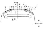
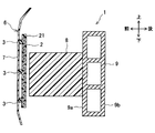
- FIG. 3 is a III-III cross-sectional view of the bumper portion of FIG. 2.
- the vehicle collision detection device 1 of this embodiment includes a piezoelectric film 2 (corresponding to a deformation sensor), an intermediate member 3, a speed sensor 4, a collision detection ECU 5, and the like. .
- This vehicle collision detection apparatus 1 detects a collision of an object (that is, a pedestrian H) with a bumper 6 provided in front of the vehicle.
- the bumper 6 is mainly composed of a bumper cover 7, a bumper absorber 8, and a bumper reinforcement 9.
- the piezoelectric film 2 is a thin-film member that is configured to include a piezoelectric element sandwiched between a pair of electrodes, although not shown.
- the piezoelectric film 2 has a rectangular shape that is long in the vehicle width direction (that is, the left-right direction of the vehicle and the lateral direction of the vehicle), and as shown in FIGS. 1 and 2, along the vehicle width direction on the vehicle rear side of the bumper cover 7.
- the piezoelectric film 2 is arrange
- the piezoelectric film 2 is made of a piezoelectric polymer material such as polyvinylidene fluoride.
- the piezoelectric film 2 outputs an electric displacement proportional to the stress when a load is applied from the outside and a stress is applied, and conversely, when an electric displacement is applied, a distortion proportional to the electric displacement is generated.
- the piezoelectric film 2 of the present embodiment is loaded with an intermediate member 3 described later, and outputs a voltage proportional to the load.
- the piezoelectric film 2 has one end (that is, the left end in the vehicle width direction) connected to the collision detection ECU 5 via a transmission line.
- the piezoelectric film 2 outputs an electric displacement (that is, a voltage) proportional to the load applied with the deformation of the bumper cover 7 at the time of collision to the collision detection ECU 5 via a signal line.
- a plurality of intermediate members 3 are arranged at a predetermined interval in the vehicle width direction between the bumper cover 7 and the piezoelectric film 2. Specifically, nine intermediate members 3 are arranged at equal intervals L in the vehicle width direction.
- the length of the interval L between the intermediate members 3 is set to be longer than the length in the vehicle width direction (for example, about 100 mm) of the bumper cover 7 that is deformed when the pedestrian H collides. Specifically, the length of the interval L is set to about 200 mm, for example.
- each intermediate member 3 is, for example, bonded and fixed to the rear surface of the bumper cover 7 and the front surface of the piezoelectric film 2.
- Each intermediate member 3 has a rectangular cross-sectional shape and extends in the vehicle vertical direction.
- Each intermediate member 3 is made of synthetic rubber (for example, ethylene propylene rubber), and as shown in FIG. 8, a predetermined load load at a high temperature is higher than a deformation amount S1 with respect to a predetermined load load F at a low temperature. It has a temperature characteristic that the deformation amount S2 with respect to F becomes larger.
- the material of the intermediate member 3 may be any material as long as it has a temperature characteristic equal to or higher than that of the bumper cover 7 shown in FIG. 7, and may be an elastomer, a synthetic resin, or the like.
- the speed sensor 4 is a sensor device that detects the speed of the vehicle, and is electrically connected to the collision detection ECU 5 via a signal line. The speed sensor 4 transmits a signal proportional to the vehicle speed to the collision detection ECU 5.
- the collision detection ECU 5 is composed mainly of a CPU, and controls the overall operation of the vehicle collision detection apparatus 1. As shown in FIGS. 1 and 4, the collision detection ECU 5 is provided in the vehicle and is electrically connected to the piezoelectric film 2, the speed sensor 4, and the pedestrian protection device 10. A voltage signal from the piezoelectric film 2, a speed signal from the speed sensor 4, and the like are input to the collision detection ECU 5. The collision detection ECU 5 executes a predetermined collision determination process on the basis of the voltage signal from the piezoelectric film 2 output along with the deformation of the bumper cover 7 and the speed signal from the speed sensor 4, and outputs to the bumper cover 7. A collision of an object such as a pedestrian H is detected. When the collision detection ECU 5 determines that a collision with a pedestrian has occurred, the collision detection ECU 5 outputs a control signal to operate the pedestrian protection device 10.
- the bumper 6 is for reducing a shock at the time of a vehicle collision, and includes a bumper cover 7, a bumper absorber 8, a bumper reinforcement 9, and the like.
- the bumper cover 7 is provided so as to cover the components of the bumper 6 and is a resin member such as polypropylene.
- the bumper cover 7 constitutes the appearance of the bumper 6 and at the same time constitutes a part of the appearance of the entire vehicle.
- the bumper absorber 8 is disposed at a position facing the front surface 9 a of the bumper reinforcement 9.
- the bumper absorber 8 is a member that has a shock absorbing action in the bumper 6 when it collides with a pedestrian H of the vehicle, and is made of, for example, foamed polypropylene.
- the bumper reinforcement 9 is a rigid member made of metal such as aluminum which is disposed in the bumper cover 7 and extends in the vehicle width direction. As shown in FIG. It is.
- the bumper reinforcement 9 has a front surface 9a that is a surface on the front side of the vehicle and a rear surface 9b that is a surface on the rear side of the vehicle.
- the bumper reinforcement 9 is attached to the front end of a side member 11 that is a pair of metal members extending in the vehicle front-rear direction.
- the piezoelectric film 2 is disposed on the vehicle rear side of the bumper cover 7 provided in the front of the vehicle via the intermediate member 3, and an impact caused by the collision with the pedestrian H in the front of the vehicle is It is transmitted from the bumper cover 7 to the piezoelectric film 2 via the intermediate member 3.
- the fitting convex portion provided on the rear surface of the bumper absorber 8 is fitted into the fitting concave portion provided on the front surface 9a of the bumper reinforcement 9, so that the bumper reinforcement of the bumper absorber 8 is provided. Assume that the attachment to the ment 9 is performed.
- a pop-up hood is used as the pedestrian protection device 10.
- This pop-up hood raises the rear end of the engine hood instantly after detecting a vehicle collision, increases the clearance between the pedestrian H and a hard part such as the engine, and uses that space to the pedestrian H's head. The impact energy on the head of the pedestrian H is reduced.
- a cowl airbag or the like that buffers the impact of the pedestrian H by deploying the airbag from the engine hood outside the vehicle body to the lower portion of the front window may be used.
- the operation at the time of collision of the vehicle collision detection apparatus 1 in the present embodiment will be described.
- the bumper cover 7 is deformed by an impact caused by the collision with the pedestrian H.
- an external force accompanying a collision is applied to the intermediate member 3 provided on the rear surface of the bumper cover 7, and a load is applied to the piezoelectric film 2 through the intermediate member 3.
- the piezoelectric film 2 outputs a voltage signal proportional to the applied load to the collision detection ECU 5.
- the intermediate member 3 has a temperature characteristic in which the rate of increase accompanying the temperature rise of the deformation amount with respect to the predetermined load S is equal to or higher than the rate of increase in the bumper cover 7 shown in FIG. It is what has. That is, in the intermediate member 3, the deformation amount S2 with respect to the load load S at the high temperature is larger than the deformation amount S1 with respect to the predetermined load load S at the low temperature. Accordingly, as shown in FIG. 5, since the intermediate member 3 is hard and difficult to deform at low temperatures, the external force accompanying the collision is transmitted to the piezoelectric film 2 with almost no absorption by the intermediate member 3, and the piezoelectric film 2 is deformed. To do.
- the intermediate member 3 becomes soft and deforms preferentially over the piezoelectric film 2 so that a part of the load is absorbed.
- the load is suppressed and the deformation of the piezoelectric film 2 is suppressed.
- the load applied to the piezoelectric film 2 increases as the temperature rises in the comparative example without the intermediate member 3.
- the load applied to the piezoelectric film 2 is substantially constant regardless of the temperature rise. That is, by providing the intermediate member 3 between the bumper cover 7 and the piezoelectric film 2, it is possible to prevent the voltage change of the piezoelectric film 2 from being affected by the temperature rise.
- the distortion of the piezoelectric film 2 increases because the intermediate member 3 is not easily deformed at low temperatures as shown in FIG. 5.
- the intermediate member 3 deforms preferentially over the piezoelectric film 2 as shown in FIG. 6 at a high temperature, the distortion of the piezoelectric film 2 is reduced. Thereby, it is suppressed that the output of the piezoelectric film 2 at the time of a collision varies with a temperature rise.
- the plurality of intermediate members 3 are arranged with an interval L in the vehicle width direction that is equal to or longer than the vehicle width direction length at which the bumper cover 7 is deformed when the pedestrian H collides. Accordingly, as shown in FIGS. 5 and 6, the probability that the pedestrian H collides with the range in the vehicle width direction between the adjacent intermediate members 3 can be increased, and the piezoelectric film provided by providing the intermediate member 3 described above. It is possible to obtain the output adjustment effect of No. 2 satisfactorily.
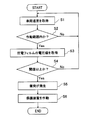
- the flow of the collision determination process performed by the vehicle collision detection apparatus 1 having the above configuration will be described with reference to the flowchart of FIG.
- this flowchart is an example, and the present invention is not limited to this.
- it is determined whether or not a collision with the pedestrian H that requires the operation of the pedestrian protection device 10 has occurred based on the detection results of the piezoelectric film 2 and the speed sensor 4.
- step S1 the collision detection ECU 5 of the vehicle collision detection device 1 acquires the vehicle speed from the output from the speed sensor 4, and the vehicle speed is predetermined in S2. It is determined whether or not it is within the operating range.
- the operating range of the vehicle speed is, for example, a range of 25 km to 55 km / h. This operating range is due to the fact that the speed at which the pedestrian protection function of the pedestrian protection device 10 acts effectively is determined by conditions such as the vehicle shape.
- the collision detection ECU 5 determines that the vehicle speed is not within the operating range, and returns to S1. On the other hand, in the case of Yes in S2, the collision detection ECU 5 determines that the vehicle speed is within the operating range, acquires the voltage value of the piezoelectric film 2 in S3, and proceeds to S4.
- the collision detection ECU 5 determines whether or not the voltage value of the piezoelectric film 2 is equal to or greater than a threshold value. If No in S4, that is, if the voltage value of the piezoelectric film 2 is less than the threshold value, the process returns to S1. On the other hand, if Yes in S4, that is, if the voltage value of the piezoelectric film 2 is equal to or greater than the threshold value, the process proceeds to S5, and the collision detection ECU 5 determines that a collision with the pedestrian H of the vehicle has occurred.
- the threshold value for collision determination is set to a value larger than the voltage value output from the piezoelectric film 2 at the time of collision with an OFF requirement target object such as a roadside marker (that is, OFF collision). This makes it possible to distinguish a collision with a pedestrian H or the like that is an ON requirement target (ie, an ON collision) and an OFF collision.
- collision detection ECU5 outputs the control signal which operates the pedestrian protection apparatus 10, and operates the pedestrian protection apparatus 10. FIG. Thereby, the impact to the pedestrian H by the collision with the pedestrian H of a vehicle is reduced.
- the vehicle collision detection apparatus 1 is provided along the vehicle width direction on the vehicle rear side of the bumper cover 7 of the vehicle, and accompanying the deformation of the bumper cover 7 at the time of the collision.
- a piezoelectric film 2 as a deformation sensor that outputs an electrical displacement (ie, voltage) according to a load applied thereto, a temperature characteristic in which a deformation amount with respect to a predetermined load load F increases as the temperature rises;
- a collision detection ECU 5 that is a collision detection unit that detects that an object (that is, a pedestrian H) has collided with the bumper cover 7.
- a plurality of intermediate members 3 having a temperature characteristic in which the deformation amount with respect to a predetermined load is increased as the temperature rises are disposed between the bumper cover 7 and the piezoelectric film 2. Since the member 3 is hard and difficult to deform, the external force accompanying the collision is transmitted to the piezoelectric film 2 without being absorbed by the intermediate member 3 and the piezoelectric film 2 is deformed. On the other hand, since the intermediate member 3 becomes soft and deforms preferentially over the piezoelectric film 2 at a high temperature and a part of the load is absorbed, the load applied to the piezoelectric film 2 is suppressed, and the deformation of the piezoelectric film 2 is prevented. It is suppressed.
- the intermediate member 3 is made of synthetic rubber, and has a temperature characteristic that an increase rate with a temperature increase of the deformation amount with respect to a predetermined load F is equal to or higher than an increase rate in the bumper cover 7.
- the intermediate member 3 is made of synthetic rubber having a temperature characteristic in which an increase rate of the deformation amount with respect to a predetermined load F with a temperature increase is equal to or higher than an increase rate in the bumper cover 7.
- the intermediate member 3 can be hard and difficult to deform, and the intermediate member 3 can be softened and easily deformed at high temperatures.
- the external force associated with the collision is transmitted to the piezoelectric film 2 almost without being absorbed by the intermediate member 3 at a low temperature, whereas the intermediate member 3 is preferentially deformed over the piezoelectric film 2 at a high temperature to cause a load load.
- the load applied to the piezoelectric film 2 can be reliably suppressed.
- the intermediate member 3 is disposed with an interval L in the vehicle width direction that is equal to or longer than the vehicle width direction length at which the bumper cover 7 is deformed when the pedestrian H collides.
- the plurality of intermediate members 3 are disposed with an interval L in the vehicle width direction that is greater than or equal to the vehicle width direction length at which the bumper cover 7 is deformed when the pedestrian H collides.
- the intermediate members 3 are arranged at equal intervals L in the vehicle width direction. According to this configuration, the plurality of intermediate members 3 are arranged at equal intervals L along the vehicle width direction between the bumper cover 7 and the piezoelectric film 2, so that the thin film-like piezoelectric film 2 is mounted on the vehicle. It is possible to reliably prevent bending in the front-rear direction, and the piezoelectric film 2 can be stably disposed at a predetermined position on the vehicle rear side of the bumper cover 7.
- the intermediate member 3 is extended in the vehicle vertical direction. According to this configuration, since the intermediate member 3 extends in the vehicle vertical direction, a bonding area between the piezoelectric film 2 and the intermediate member 3 can be secured, and the piezoelectric film 2 can be stably bonded to the intermediate member 3. Can be fixed.
- FIG. 11 the same parts as those of the above-described embodiment are denoted by the same reference numerals, description thereof is omitted, and only different parts are described.
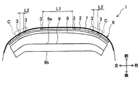
- the plurality of intermediate members 3 are arranged at different intervals in the vehicle width direction according to the vehicle width direction position of the bumper cover 7. It is installed.
- intermediate members 3 are arranged on the rear surface of the bumper cover 7. Of these, two intermediate members 3 are provided in each of the portions where the bumper cover 7 is curved in the vehicle front-rear direction, that is, the left and right corner portions C indicated by the enclosure lines in FIG. And the space
- each intermediate member 3 is sandwiched between the bumper cover 7 and the piezoelectric film 2 and extends in the vehicle vertical direction, as in the first embodiment. Further, as shown in FIG. 8, each intermediate member 3 has a temperature characteristic in which the rate of increase accompanying the temperature rise of the deformation amount with respect to a predetermined load F is equal to or higher than the rate of increase in the bumper cover 7 shown in FIG. 7. Have. Therefore, similarly to the first embodiment, by providing the plurality of intermediate members 3 at intervals in the vehicle width direction, it is possible to prevent the voltage change of the piezoelectric film 2 from being affected by the temperature rise. .
- the intermediate member 3 is disposed with different intervals L1 and L2 in the vehicle width direction according to the vehicle width direction position of the bumper cover 7, and at least The bumper cover 7 is disposed at a portion curved in the vehicle front-rear direction (that is, the corner portion C).
- the same effect as that of the first embodiment can be obtained.
- the plurality of intermediate members 3 are disposed at the corner portion C where at least the bumper cover 7 is curved in the vehicle front-rear direction, the portion where the piezoelectric film 2 is arranged in a curved state and easily falls off is provided as an intermediate member. 3 is securely supported, the piezoelectric film 2 can be more stably disposed at a predetermined position on the vehicle rear side of the bumper cover 7.
- the plurality of intermediate members 31 are arranged with a space L in the vehicle width direction and with a predetermined space in the vehicle vertical direction. Specifically, on the rear surface of the bumper cover 7, nine vehicle width direction positions spaced at equal intervals L in the vehicle width direction shown in FIG. Individual intermediate members 31 are provided.
- the distance L between the intermediate members 31 in the vehicle width direction is equal to or greater than the vehicle width direction length (for example, about 100 mm) at which the bumper cover 7 is deformed when the pedestrian H collides, as in the first embodiment. Is set to about 200 mm, for example.
- the interval between the intermediate members 31 arranged in the vehicle vertical direction is set to about 20 mm to 30 mm, for example.
- Each intermediate member 31 is sandwiched between the bumper cover 7 and the piezoelectric film 2 as in the first embodiment.
- Each intermediate member 31 is made of synthetic rubber (for example, ethylene propylene rubber). As shown in FIG. 8, the rate of increase of the deformation amount with respect to a predetermined load F as the temperature rises is shown in FIG. It has a temperature characteristic equal to or higher than the increase rate in the cover 7. Therefore, by providing the plurality of intermediate members 31 at intervals in the vehicle width direction, it is possible to prevent the voltage change of the piezoelectric film 2 from being affected by the temperature rise as in the first embodiment. .
- the intermediate member 31 is disposed at a predetermined interval in the vehicle width direction and the vehicle vertical direction.
- the same effect as that of the first embodiment can be obtained.
- FIG. 13 the same parts as those in the above embodiment are denoted by the same reference numerals, description thereof is omitted, and only different parts are described.
- a support member 21 that covers the entire outer peripheral portion of the piezoelectric film 2 is provided.
- the support member 21 is made of a material (for example, synthetic resin) having higher rigidity than the piezoelectric film 2 and supports the piezoelectric film 2.
- the support member 21 is a rectangular plate-like member that covers the entire outer peripheral portion of the piezoelectric film 2, and is provided on the vehicle rear side of the bumper cover 7 along the vehicle width direction.
- the plurality of intermediate members 31 are spaced apart in the vehicle width direction shown in FIG. 2 and spaced apart in the vehicle vertical direction. Arranged. Specifically, on the rear surface of the bumper cover 7, there are 27 intermediate members, three in each of the nine positions in the vehicle width direction at equal intervals L in the vehicle width direction and spaced in the vehicle vertical direction. 31 is provided.
- the distance L between the intermediate members 31 in the vehicle width direction is set to about 200 mm, for example.
- the interval between the intermediate members 31 arranged in the vehicle vertical direction is set to about 20 mm to 30 mm, for example.
- each intermediate member 31 is sandwiched between the bumper cover 7 and the piezoelectric film 2 whose entire outer periphery is covered with the support member 21.
- the support member 21 and the intermediate member 31 are bonded and fixed, for example.
- each intermediate member 31 is made of, for example, synthetic rubber.
- the rate of increase of the deformation amount with respect to a predetermined load F as the temperature rises is as shown in FIG. 7. It has a temperature characteristic that is equal to or higher than the increase rate in the bumper cover 7 shown. Further, it is assumed that the support member 21 has a rigidity that does not hinder the deformation of the piezoelectric film 2 at the time of collision.
- the operation at the time of collision of the vehicle collision detection apparatus 1 in the fourth embodiment will be described.
- the bumper cover 7 is deformed by an impact caused by the collision with the pedestrian H.
- an external force associated with the collision is applied to the intermediate member 31 provided on the rear surface of the bumper cover 7, and a load is applied to the piezoelectric film 2 whose entire outer periphery is covered by the support member 21 via the intermediate member 31.
- the piezoelectric film 2 outputs a voltage signal proportional to the applied load to the collision detection ECU 5.
- the plurality of intermediate members 31 are arranged at intervals in the vehicle width direction, it is possible to prevent the voltage change of the piezoelectric film 2 from being affected by the temperature rise. It has become.
- the same effect as that of the first embodiment can be obtained.
- the entire outer peripheral portion of the piezoelectric film 2 is covered with the support member 21, the thin film-like piezoelectric film 2 can be stably fixed to the intermediate member 3.
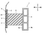
- the support member 22 is provided on the surface of the piezoelectric film 2 on the vehicle front side.
- the support member 22 is bonded and fixed between the intermediate member 3 and the piezoelectric film 2.
- the support member 22 is made of a material (for example, synthetic resin) having higher rigidity than the piezoelectric film 2.
- the support member 22 is a rectangular plate-like member, and is provided on the vehicle rear side of the bumper cover 7 along the vehicle width direction.
- the support member 22 is assumed to have a rigidity that does not hinder the deformation of the piezoelectric film 2 at the time of collision.
- the plurality of intermediate members 3 are arranged at intervals L in the vehicle width direction, as in the first embodiment. Specifically, as shown in FIG. 2, nine intermediate members 3 are arranged at equal intervals L in the vehicle width direction.
- the intermediate member 3 of the fifth embodiment is disposed between the piezoelectric film 2 and the bumper cover 7 via the support member 22.
- Each intermediate member 3 is made of, for example, synthetic rubber, as in the first embodiment.
- the rate of increase accompanying the temperature rise of the deformation amount with respect to a predetermined load F is shown in FIG. 7. It has a temperature characteristic that is equal to or higher than the increase rate in the bumper cover 7 shown.
- the operation at the time of collision of the vehicle collision detection apparatus 1 in the fifth embodiment will be described.
- the bumper cover 7 is deformed by an impact caused by the collision with the pedestrian H.
- an external force due to the collision is applied to the intermediate member 3 provided on the rear surface of the bumper cover 7, and a load is applied to the piezoelectric film 2 whose outer peripheral portion is covered with the support member 22 through the intermediate member 3.
- the piezoelectric film 2 outputs a voltage signal proportional to the applied load to the collision detection ECU 5.
- the some intermediate member 3 at intervals in the vehicle width direction, it is possible to prevent the voltage change of the piezoelectric film 2 from being affected by the temperature rise as in the first embodiment. .
- the piezoelectric film 2 is covered with the support member 22 on the rear side of the outer peripheral portion. Also in the vehicle collision detection apparatus 1 of the fifth embodiment, the same effect as that of the first embodiment can be obtained. In particular, since the rear side of the outer peripheral portion of the piezoelectric film 2 is covered by the support member 22, it can be disposed on the rear side of the bumper cover 7 with the thin film-like piezoelectric film 2 stably supported.
- the piezoelectric film 2 shall be used as a deformation
- a pyrofilm made of pyroelectric material may be used.
- the electric displacement means a change in electric energy.
- the electric displacement includes a change in an optical signal, and an optical fiber may be used as a deformation sensor.
- the piezoelectric film 2 is disposed on the surface of the support member 22 on the vehicle rear side.
- the piezoelectric film 2 may be disposed on the surface of the support member 22 on the vehicle front side.
Landscapes
- Engineering & Computer Science (AREA)
- Mechanical Engineering (AREA)
- Force Measurement Appropriate To Specific Purposes (AREA)
Abstract
車両用衝突検知装置(1)は、車両のバンパカバー(7)の車両後方側に車幅方向に沿って設けられ、衝突時におけるバンパカバーの変形に伴って負荷される荷重により電気変位を出力する変形センサとしての圧電フィルム(2)と、所定の負荷荷重に対する変形量が温度上昇に伴って増加する温度特性を有し、バンパカバーと圧電フィルムとの間に挟装され且つ車幅方向に間隔をあけて複数配置された中間部材(3)と、バンパカバーの変形に伴って出力される圧電フィルムの電気変位に基づいて、バンパカバーへ歩行者が衝突したことを検出する衝突検知ECU(5)と、を備えている。したがって、温度変化に伴う衝突検知精度の低下を防止できる。
Description
本出願は、当該開示内容が参照によって本出願に組み込まれた、2016年3月16日に出願された日本特許出願2016-052416を基にしている。
本開示は、車両への歩行者等の衝突を検出する車両用衝突検知装置に関する。
従来、車両に衝突が発生したことを検出するための車両用衝突検知装置として、圧電フィルム等の変形センサを有して構成された車両用衝突検知装置を備えた車両がある。この車両用衝突検知装置では、バンパカバーの内面に車幅方向に沿って面状の圧電フィルムが設けられ、車両の前面における衝突を検出するものである。圧電フィルムは、圧電性高分子材料等からなり、歪みを与えると電荷を発生させ、逆に電荷を与えると歪みを生じるものである。この構成の車両用衝突検知装置では、バンパカバーへ歩行者等が衝突すると、バンパカバーの変形に伴って圧電フィルムが変形し、圧電フィルムの電圧が変化する。この電圧変化を検出することに基づいて、車両に衝突が発生したことを検知している。
上記した車両用衝突検知装置では、例えば被覆部材で被覆された圧電フィルム等の変形センサをバンパカバーの裏面に車幅方向に沿って取り付ける構造となっている。ここで、バンパカバーは、ポリプロピレン等の樹脂製の部材からなるもので、温度が高くなると所定の負荷荷重に対する変形量が大きくなるという温度特性を有している。このため、温度が高くなると衝突時におけるバンパカバーの変形量が増加し、これに伴って圧電フィルムの電圧変化も大きくなる。従って、上記変形センサを有する車両用衝突検知装置では、バンパに加わる衝撃力が同一であっても温度によって変形センサの出力が異なることが想定されるため、衝突時の変形センサの出力が温度変化に伴ってばらつくことに起因して衝突検知精度が低下する場合がある。
本開示は、温度変化に伴う衝突検知精度の低下を防止可能とした車両用衝突検知装置を提供することを目的とする。
本開示の一態様によると、車両用衝突検知装置は、車両のバンパカバーの車両後方側に車幅方向に沿って設けられ、衝突時におけるバンパカバーの変形に伴って負荷される荷重により電気変位を出力する変形センサと、所定の負荷荷重に対する変形量が温度上昇に伴って増加する温度特性を有し、バンパカバーと変形センサとの間に挟装され且つ車幅方向に間隔をあけて複数配置された中間部材と、バンパカバーの変形に伴って出力される変形センサの電気変位に基づいて、バンパカバーへ物体が衝突したことを検出する衝突検知部と、を備えている。
この構成によれば、バンパカバーと変形センサとの間に、所定の負荷荷重に対する変形量が温度上昇に伴って増加する温度特性を有する中間部材を複数配置することにより、低温時には中間部材が固く変形し難いため、衝突に伴う外力が中間部材において殆ど吸収されることなく変形センサへ伝達されて変形センサが変形する。一方、高温時には中間部材が柔らかくなって変形センサよりも優先的に変形して負荷荷重の一部が吸収されるので、変形センサに加わる負荷荷重が抑制され、変形センサの変形が抑制される。これにより、温度上昇に伴って変形センサの電圧変化が大きくなることを防ぐことができ、衝突時の変形センサの出力が温度変化に伴ってばらつくことに起因する車両用衝突検知装置の衝突検知精度の低下を防止できる。
以下に、図面を参照しながら本開示を実施するための複数の形態を説明する。各形態において先行する形態で説明した事項に対応する部分には同一の参照符号を付して重複する説明を省略する場合がある。各形態において構成の一部のみを説明している場合は、構成の他の部分については先行して説明した他の形態を適用することができる。各実施形態で具体的に組合せが可能であることを明示している部分同士の組合せばかりではなく、特に組合せに支障が生じなければ、明示してなくとも実施形態同士を部分的に組み合せることも可能である。
[第1の実施形態]
以下、本開示の第1の実施形態の車両用衝突検知装置について、図1~図10を参照して説明する。図1及び図2に示すように、本実施形態の車両用衝突検知装置1は、圧電フィルム2(変形センサに相当)、中間部材3、速度センサ4、衝突検知ECU5等を備えて構成される。この車両用衝突検知装置1は、車両前方に設けられたバンパ6への物体(即ち、歩行者H)の衝突を検知するものである。このバンパ6は、図3にも示すように、バンパカバー7、バンパアブソーバ8、バンパレインフォースメント9を主体として構成されている。
以下、本開示の第1の実施形態の車両用衝突検知装置について、図1~図10を参照して説明する。図1及び図2に示すように、本実施形態の車両用衝突検知装置1は、圧電フィルム2(変形センサに相当)、中間部材3、速度センサ4、衝突検知ECU5等を備えて構成される。この車両用衝突検知装置1は、車両前方に設けられたバンパ6への物体(即ち、歩行者H)の衝突を検知するものである。このバンパ6は、図3にも示すように、バンパカバー7、バンパアブソーバ8、バンパレインフォースメント9を主体として構成されている。
圧電フィルム2は、図示しないが、一対の電極に挟まれたピエゾ素子を有して構成された薄膜状の部材である。圧電フィルム2は、車幅方向(即ち、車両左右方向、車両横方向)に長い矩形状をなし、図1及び図2に示すように、バンパカバー7の車両後方側に車幅方向に沿って設けられる。また、圧電フィルム2は、図3に示すように、バンパカバー7の車両後方側において、歩行者Hが衝突すると想定される車両上下方向の位置に配置される。
圧電フィルム2は、例えばポリフッ化ビニリデン等の圧電性高分子材料からなる。この圧電フィルム2は、外部から荷重を負荷して応力を加えると応力に比例した電気変位を出力し、逆に電気変位を与えると電気変位に比例した歪みを生じるものである。本実施形態の圧電フィルム2は、歩行者H等との衝突によりバンパカバー7が変形すると、後述する中間部材3を介して荷重が負荷され、この負荷荷重に比例した電圧を出力する。
また、圧電フィルム2は、図1に示すように、その一端部(即ち、車幅方向左側端部)が伝送線を介して衝突検知ECU5に接続されている。圧電フィルム2は、衝突時におけるバンパカバー7の変形に伴って負荷される荷重に比例した電気変位(即ち、電圧)を、信号線を介して衝突検知ECU5へ出力する。
本実施形態では、バンパカバー7と圧電フィルム2との間に、複数の中間部材3が車幅方向に所定の間隔をあけて配置されている。具体的には、中間部材3は、車幅方向に等間隔Lをあけて、9つ配設されている。各中間部材3どうしの間隔Lの長さは、歩行者Hの衝突時に変形するバンパカバー7の部分の車幅方向長さ(例えば、100mm程度)以上に設定されている。具体的には、間隔Lの長さは、例えば200mm程度に設定されている。
複数の中間部材3は、それぞれバンパカバー7と圧電フィルム2との間に挟装されている。具体的には、各中間部材3は、バンパカバー7の後面及び圧電フィルム2の前面に、例えば接着固定されている。各中間部材3は、矩形の断面形状を有し、車両上下方向に延設されている。
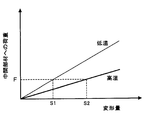
また、各中間部材3は、合成ゴム(例えば、エチレンプロピレンゴム等)からなり、図8に示すように、低温時における所定の負荷荷重Fに対する変形量S1よりも、高温時における所定の負荷荷重Fに対する変形量S2の方が大きくなる温度特性を有している。中間部材3の材質としては、図7に示すバンパカバー7の温度特性と同等以上の温度特性を有するものであればよく、他にもエラストマー、合成樹脂などでもよい。
速度センサ4は、車両の速度を検出するセンサ装置であり、衝突検知ECU5に信号線を介して電気的に接続されている。この速度センサ4は、車両速度に比例した信号を衝突検知ECU5へ送信する。
衝突検知ECU5は、CPUを主体として構成され、車両用衝突検知装置1の動作全般を制御するものである。衝突検知ECU5は、図1及び図4に示すように、車両内に設けられ、圧電フィルム2、速度センサ4、及び歩行者保護装置10のそれぞれに電気的に接続されている。衝突検知ECU5には、圧電フィルム2からの電圧信号、速度センサ4からの速度信号等が入力される。衝突検知ECU5は、バンパカバー7の変形に伴って出力される圧電フィルム2からの電圧信号、及び速度センサ4からの速度信号に基づいて、所定の衝突判定処理を実行し、バンパカバー7への歩行者H等の物体の衝突を検出する。衝突検知ECU5は、歩行者との衝突が発生したものと判定した場合、制御信号を出力して歩行者保護装置10を作動させる。
バンパ6は、車両の衝突時における衝撃を和らげるためのものであり、バンパカバー7、バンパアブソーバ8、バンパレインフォースメント9等から構成される。バンパカバー7は、バンパ6の構成部品を覆うように設けられ、ポリプロピレン等の樹脂製の部材である。このバンパカバー7は、バンパ6の外観を構成すると同時に、車両全体の外観の一部を構成するものとなっている。
バンパアブソーバ8は、バンパレインフォースメント9の前面9aに対向する位置に配設される。このバンパアブソーバ8は、車両の歩行者H等との衝突時にバンパ6において衝撃吸収の作用を受け持つ部材であり、例えば発泡ポリプロピレン等からなる。
バンパレインフォースメント9は、バンパカバー7内に配設されて車幅方向に延びるアルミニウム等の金属製の剛性部材であって、図3に示すように、内部中央に梁が設けられた中空部材である。また、バンパレインフォースメント9は、車両前方側の面である前面9aと、車両後方側の面である後面9bとを有している。このバンパレインフォースメント9は、図1及び図2に示すように、車両前後方向に延びる一対の金属製部材であるサイドメンバ11の前端に取り付けられる。
通常、車両の衝突事故においては、車両の進行方向(即ち、車両前方)に存在する歩行者H等と衝突する場合が多い。このため、本実施形態では、圧電フィルム2を車両前方に設けられたバンパカバー7の車両後方側に中間部材3を介して配設し、車両前方の歩行者Hとの衝突に伴う衝撃が、バンパカバー7から中間部材3を介して圧電フィルム2に伝わるようにしている。
なお、図示しないが、バンパアブソーバ8の後面に設けられた嵌合凸部が、バンパレインフォースメント9の前面9aに設けられた嵌合凹部に嵌め合わされることにより、バンパアブソーバ8のバンパレインフォースメント9への組付けが行われるものとする。
歩行者保護装置10としては、例えばポップアップフードを用いる。このポップアップフードは、車両の衝突検知後瞬時に、エンジンフードの後端を上昇させ、歩行者Hとエンジン等の硬い部品とのクリアランスを増加させ、そのスペースを用いて歩行者Hの頭部への衝突エネルギーを吸収し、歩行者Hの頭部への衝撃を低減させるものである。なお、ポップアップフードの代わりに、車体外部のエンジンフード上からフロントウィンド下部にかけてエアバッグを展開させて歩行者Hの衝撃を緩衝するカウルエアバッグ等を用いてもよい。
次に、本実施形態における車両用衝突検知装置1の衝突時の動作について説明する。車両前方に歩行者H等の物体が衝突した際には、バンパカバー7が歩行者Hとの衝突による衝撃により変形する。続いて、バンパカバー7の後面に設けられた中間部材3に衝突に伴う外力が加わると共に、中間部材3を介して圧電フィルム2へ荷重が加わる。このとき、圧電フィルム2は、負荷された荷重に比例した電圧信号を衝突検知ECU5へ出力する。
ここで、上記中間部材3は、図8に示すように、所定の負荷荷重Sに対する変形量の温度上昇に伴う増加率が、図7に示すバンパカバー7における増加率と同等以上である温度特性を有するものである。即ち、中間部材3は、低温時における所定の負荷荷重Sに対する変形量S1に比べ、高温時における負荷荷重Sに対する変形量S2の方が大きくなる。これにより、低温時には、図5に示すように、中間部材3が固く変形し難いため、衝突に伴う外力が中間部材3において殆ど吸収されることなく圧電フィルム2へ伝達されて圧電フィルム2が変形する。これに対して、高温時には、図6に示すように、中間部材3が柔らかくなって圧電フィルム2よりも優先的に変形して負荷荷重の一部が吸収されるので、圧電フィルム2に加わる負荷荷重が抑制され、圧電フィルム2の変形が抑制される。
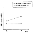
従って、図9に示すように、バンパカバー7に加わる衝撃力を同一として温度を変化させた場合、中間部材3がない比較例では、圧電フィルム2に加わる負荷荷重が温度上昇に伴って大きくなるのに対し、中間部材3を有する本実施形態では、圧電フィルム2に加わる負荷荷重は温度上昇に拘わらず略一定である。つまり、バンパカバー7と圧電フィルム2との間に中間部材3を設けることによって、圧電フィルム2の電圧変化が温度上昇の影響を受けることを防ぐことを可能としている。
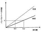
即ち、バンパカバー7と圧電フィルム2との間に中間部材3がない比較例では、図7に示すように、低温時における所定の負荷荷重Fに対するバンパカバー7の変形量Sb1よりも、高温時における負荷荷重Fに対するバンパカバー7の変形量Sb2の方が大きくなる。このため、バンパカバー7の温度上昇に伴う変形量の増加率が圧電フィルム2の変形量に直接影響を与え、温度上昇に伴って衝突時における圧電フィルム2の出力が大きくなる。一方、バンパカバー7と圧電フィルム2との間に中間部材3がある本実施形態では、低温時には、図5に示すように中間部材3が変形し難いため圧電フィルム2の歪みが大きくなる。これに対して、高温時には、図6に示すように中間部材3が圧電フィルム2よりも優先的に変形するため、圧電フィルム2の歪みが小さくなる。これにより、温度上昇に伴って衝突時の圧電フィルム2の出力がばらつくことを抑止している。
更に、本実施形態では、複数の中間部材3は、歩行者Hの衝突時にバンパカバー7が変形する車幅方向長さ以上の間隔Lを車幅方向にあけて配設されている。これにより、図5及び図6に示すように、隣接した中間部材3の間の車幅方向範囲に歩行者Hが衝突する確率を高めることができ、上記した中間部材3を設けることによる圧電フィルム2の出力調節効果を良好に得ることが可能となっている。
次に、上記構成を有する車両用衝突検知装置1による衝突判定処理の流れについて、図10のフローチャートも参照して説明する。ただし、このフローチャートは一例であり、これに限定されるものではない。本実施形態の衝突判定処理においては、圧電フィルム2及び速度センサ4の検出結果に基づいて、歩行者保護装置10の作動を要する歩行者Hとの衝突が発生したか否かの判定を行う。
まず、図10のフローチャートにおいて、ステップS1(以下、ステップを省略)において、車両用衝突検知装置1の衝突検知ECU5は、速度センサ4からの出力により車両速度を取得し、S2において車両速度が所定の作動範囲内か否かの判定を行う。この車両速度の作動範囲としては、例えば時速25km~55kmの範囲であるとする。この作動範囲は、歩行者保護装置10の歩行者保護機能が有効に作用する速度が車両形状等の条件によって決まっていることによる。
S2でNoの場合、衝突検知ECU5は、車両速度が作動範囲内でないものと判定し、S1に戻る。一方、S2でYesの場合、衝突検知ECU5は、車両速度が作動範囲内であるものと判定し、S3において圧電フィルム2の電圧値を取得し、S4へ進む。
S4では、衝突検知ECU5は、圧電フィルム2の電圧値が閾値以上か否かの判定を行う。S4でNoの場合、即ち、圧電フィルム2の電圧値が閾値未満の場合にはS1に戻る。一方、S4でYesの場合、即ち、圧電フィルム2の電圧値が閾値以上の場合、S5へ進み、衝突検知ECU5は、車両の歩行者Hとの衝突が発生したものと判定する。
なお、衝突判定の閾値は、ロードサイドマーカ等のOFF要件対象物との衝突(即ち、OFF衝突)時に圧電フィルム2から出力される電圧値よりも大きな値に設定されている。これにより、ON要件対象物である歩行者H等との衝突(即ち、ON衝突)とOFF衝突とを区別できるようにしている。
そして、S6において、衝突検知ECU5は、歩行者保護装置10を作動させる制御信号を出力して、歩行者保護装置10を作動させる。これにより、車両の歩行者Hとの衝突による歩行者Hへの衝撃を低減させる。
以上説明したように、第1の実施形態の車両用衝突検知装置1は、車両のバンパカバー7の車両後方側に車幅方向に沿って設けられ、衝突時におけるバンパカバー7の変形に伴って負荷される荷重により電気変位(即ち、電圧)を出力する変形センサとしての圧電フィルム2と、所定の負荷荷重Fに対する変形量が温度上昇に伴って増加する温度特性を有し、バンパカバー7と圧電フィルム2との間に挟装され且つ車幅方向に間隔Lをあけて複数配置された中間部材3と、バンパカバー7の変形に伴って出力される圧電フィルム2の電気変位に基づいて、バンパカバー7へ物体(即ち、歩行者H)が衝突したことを検出する衝突検知部である衝突検知ECU5と、を備えている。
この構成によれば、バンパカバー7と圧電フィルム2との間に、所定の負荷荷重に対する変形量が温度上昇に伴って増加する温度特性を有する中間部材3を複数配置することにより、低温時には中間部材3が固く変形し難いため、衝突に伴う外力が中間部材3において殆ど吸収されることなく圧電フィルム2へ伝達されて圧電フィルム2が変形する。一方、高温時には中間部材3が柔らかくなって圧電フィルム2よりも優先的に変形して負荷荷重の一部が吸収されるので、圧電フィルム2に加わる負荷荷重が抑制され、圧電フィルム2の変形が抑制される。これにより、圧電フィルム2の電圧変化が温度上昇の影響を受けることを防ぐことができ、衝突時の圧電フィルム2の出力が温度変化に伴ってばらつくことに起因する車両用衝突検知装置1の衝突検知精度の低下を防止できる。
また、中間部材3は、合成ゴムからなり、所定の負荷荷重Fに対する変形量の温度上昇に伴う増加率がバンパカバー7における増加率と同等以上である温度特性を有する。
この構成によれば、中間部材3は、所定の負荷荷重Fに対する変形量の温度上昇に伴う増加率がバンパカバー7における増加率と同等以上である温度特性を有する合成ゴムからなるので、低温時には中間部材3を固く変形し難くでき、高温時には中間部材3を柔らかくして変形し易くできる。これにより、低温時には衝突に伴う外力が中間部材3において殆ど吸収されることなく圧電フィルム2へ伝達されるのに対し、高温時には中間部材3が圧電フィルム2よりも優先的に変形して負荷荷重の一部を吸収することで、圧電フィルム2に加わる負荷荷重を確実に抑制できる。
また、中間部材3は、歩行者Hの衝突時にバンパカバー7が変形する車幅方向長さ以上の間隔Lを車幅方向にあけて配設されている。この構成によれば、複数の中間部材3が、歩行者Hの衝突時にバンパカバー7が変形する車幅方向長さ以上の間隔Lを車幅方向にあけて配設されているので、図5及び図6に示すように、隣接した中間部材3の間の車幅方向位置において歩行者Hが衝突するようにして、上記した中間部材3を設けることによる温度上昇時における圧電フィルム2の出力調節効果を良好に得ることが可能である。
また、中間部材3は、車幅方向に等間隔Lをあけて配設されている。この構成によれば、バンパカバー7と圧電フィルム2との間に、複数の中間部材3を車幅方向に沿って等間隔Lをあけて配設することにより、薄膜状の圧電フィルム2が車両前後方向に撓むことを確実に防止することができ、バンパカバー7の車両後方側の所定の位置に圧電フィルム2を安定して配置することができる。
また、中間部材3は、車両上下方向に延設されている。この構成によれば、中間部材3が車両上下方向に延設されているので、圧電フィルム2と中間部材3との接合面積を確保でき、圧電フィルム2を中間部材3に対して安定して接着固定できる。
[第2の実施形態]
次に、本開示の第2の実施形態について、図11を参照して説明する。尚、図11において上記実施形態と同一部分には同一の符号を付して説明を省略し、異なる部分についてだけ説明する。この第2の実施形態の車両用衝突検知装置1では、図11に示すように、複数の中間部材3が、バンパカバー7の車幅方向位置に応じて車幅方向に異なる間隔をあけて配設されている。
次に、本開示の第2の実施形態について、図11を参照して説明する。尚、図11において上記実施形態と同一部分には同一の符号を付して説明を省略し、異なる部分についてだけ説明する。この第2の実施形態の車両用衝突検知装置1では、図11に示すように、複数の中間部材3が、バンパカバー7の車幅方向位置に応じて車幅方向に異なる間隔をあけて配設されている。
具体的には、中間部材3は、バンパカバー7の後面に8つ配設されている。このうち、4つの中間部材3が、バンパカバー7が車両前後方向に湾曲した部分、即ち、図11の囲い線で示される左右のコーナ部Cに、それぞれ2つずつ設けられている。そして、このコーナ部Cにおける各中間部材3どうしの間隔L2が、他の部分、例えば車両前方のバンパカバー7が直線状をなしている部分の間隔L1よりも狭くなっている。
即ち、間隔L1は、例えば、300mm~400mm程度に設定されている。一方、間隔L2は、例えば50mm程度に設定されている。なお、各中間部材3は、第1の実施形態と同様に、それぞれバンパカバー7と圧電フィルム2との間に挟装され、車両上下方向に延設されている。また、各中間部材3は、図8に示すように、所定の負荷荷重Fに対する変形量の温度上昇に伴う増加率が、図7に示すバンパカバー7における増加率と同等以上である温度特性を有している。従って、第1の実施形態と同様に、複数の中間部材3を車幅方向に間隔をあけて設けることによって、圧電フィルム2の電圧変化が温度上昇の影響を受けることを防止可能となっている。
以上説明した第2の実施形態の車両用衝突検知装置1では、中間部材3は、バンパカバー7の車幅方向位置に応じて車幅方向に異なる間隔L1,L2をあけて配設され、少なくともバンパカバー7が車両前後方向に湾曲した部分(即ち、コーナ部C)に配設されている。
この第2の実施形態の車両用衝突検知装置1においても、第1の実施形態と同様の効果を得ることができる。特に、少なくともバンパカバー7が車両前後方向に湾曲したコーナ部Cに中間部材3が複数配設されているので、圧電フィルム2が湾曲した状態で配置されて脱落し易くなった部分を、中間部材3により確実に支持することで、バンパカバー7の車両後方側の所定の位置に圧電フィルム2をより安定して配置できる。
[第3の実施形態]
次に、本開示の第3の実施形態について、図12を参照して説明する。尚、図12において上記実施形態と同一部分には同一の符号を付して説明を省略し、異なる部分についてだけ説明する。
次に、本開示の第3の実施形態について、図12を参照して説明する。尚、図12において上記実施形態と同一部分には同一の符号を付して説明を省略し、異なる部分についてだけ説明する。
第3の実施形態の車両用衝突検知装置1では、複数の中間部材31が、車幅方向に間隔Lをあけ、且つ車両上下方向にも所定の間隔をあけて配設されている。具体的には、バンパカバー7の後面において、図2に示す車幅方向に等間隔Lをあけた9箇所の車幅方向位置に、車両上下方向に間隔をあけてそれぞれ3つずつ、計27個の中間部材31が設けられている。
各中間部材31どうしの車幅方向の間隔Lは、第1の実施形態と同様に、歩行者Hの衝突時にバンパカバー7が変形する車幅方向長さ(例えば、100mm程度)以上、具体的には、例えば200mm程度に設定されている。また、車両上下方向に並べられた各中間部材31どうしの間隔は、例えば20mm~30mm程度に設定されている。
なお、各中間部材31は、第1の実施形態と同様に、それぞれバンパカバー7と圧電フィルム2との間に挟装される。また、各中間部材31は、合成ゴム(例えば、エチレンプロピレンゴム等)からなり、図8に示すように、所定の負荷荷重Fに対する変形量の温度上昇に伴う増加率が、図7に示すバンパカバー7における増加率と同等以上である温度特性を有している。従って、複数の中間部材31を車幅方向に間隔をあけて設けることによって、第1の実施形態と同様に、圧電フィルム2の電圧変化が温度上昇の影響を受けることを防止可能となっている。
以上説明した第3の実施形態の車両用衝突検知装置1では、中間部材31は、車幅方向且つ車両上下方向に所定の間隔をあけて配設されている。この第3の実施形態の車両用衝突検知装置1においても、第1の実施形態と同様の効果を得ることができる。
[第4の実施形態]
次に、本開示の第4の実施形態について、図13を参照して説明する。尚、図13において上記実施形態と同一部分には同一の符号を付して説明を省略し、異なる部分についてだけ説明する。この第4の実施形態の車両用衝突検知装置1においては、圧電フィルム2の外周部全体を覆う支持部材21が設けられている。
次に、本開示の第4の実施形態について、図13を参照して説明する。尚、図13において上記実施形態と同一部分には同一の符号を付して説明を省略し、異なる部分についてだけ説明する。この第4の実施形態の車両用衝突検知装置1においては、圧電フィルム2の外周部全体を覆う支持部材21が設けられている。
支持部材21は、圧電フィルム2よりも剛性が高い材質(例えば、合成樹脂等)からなり、圧電フィルム2を支持するためのものである。この支持部材21は、圧電フィルム2の外周部全体を覆う矩形板状の部材であって、バンパカバー7の車両後方側に車幅方向に沿って設けられる。
この第4の実施形態では、上記第3の実施形態と同様に、複数の中間部材31が、図2に示す車幅方向に間隔Lをあけ、且つ車両上下方向にも所定の間隔をあけて配設される。具体的には、バンパカバー7の後面において、車幅方向に等間隔Lをあけた9箇所の車幅方向位置に、車両上下方向に間隔をあけてそれぞれ3個ずつ、計27個の中間部材31が設けられている。各中間部材31どうしの車幅方向の間隔Lは、例えば200mm程度に設定されている。また、車両上下方向に並べられた各中間部材31どうしの間隔は、例えば20mm~30mm程度に設定されている。
各中間部材31は、バンパカバー7と、支持部材21に外周部全体を覆われた圧電フィルム2との間にそれぞれ挟装される。支持部材21と中間部材31とは、例えば接着固定される。なお、各中間部材31は、第1の実施形態と同様に、例えば合成ゴムからなり、図8に示すように、所定の負荷荷重Fに対する変形量の温度上昇に伴う増加率が、図7に示すバンパカバー7における増加率と同等以上である温度特性を有している。また、支持部材21は、衝突時における圧電フィルム2の変形を阻害しない程度の剛性であるとする。
次に、第4の実施形態における車両用衝突検知装置1の衝突時の動作について説明する。車両前方に歩行者H等が衝突した際には、バンパカバー7が歩行者Hとの衝突による衝撃により変形する。続いて、バンパカバー7の後面に設けられた中間部材31に衝突に伴う外力が加わると共に、中間部材31を介して、支持部材21により外周部全体を覆われた圧電フィルム2へ荷重が加わる。このとき、圧電フィルム2は、負荷された荷重に比例した電圧信号を衝突検知ECU5へ出力する。なお、第1の実施形態と同様に、複数の中間部材31が車幅方向に間隔をあけて配設されているので、圧電フィルム2の電圧変化が温度上昇の影響を受けることを防止可能となっている。
以上説明した第4の実施形態の車両用衝突検知装置1においても、第1の実施形態と同様の効果を得ることができる。特に、圧電フィルム2の外周部全体が支持部材21により覆われているので、薄膜状の圧電フィルム2を中間部材3に対して安定して固定することができる。
[第5の実施形態]
次に、本開示の第5の実施形態について、図14を参照して説明する。尚、図14において上記実施形態と同一部分には同一の符号を付して説明を省略し、異なる部分についてだけ説明する。
次に、本開示の第5の実施形態について、図14を参照して説明する。尚、図14において上記実施形態と同一部分には同一の符号を付して説明を省略し、異なる部分についてだけ説明する。
第5の実施形態では、圧電フィルム2の車両前方側の面に、支持部材22が設けられている。この支持部材22は、中間部材3と圧電フィルム2との間に接着固定される。支持部材22は、圧電フィルム2よりも剛性が高い材質(例えば、合成樹脂等)からなる。この支持部材22は、矩形板状の部材であって、バンパカバー7の車両後方側に、車幅方向に沿って設けられる。なお、支持部材22は、衝突時における圧電フィルム2の変形を阻害しない程度の剛性であるとする。
また、第5の実施形態では、複数の中間部材3が、上記第1の実施形態と同様に、車幅方向に間隔Lをあけて配設されている。具体的には、中間部材3は、図2に示すように、車幅方向に等間隔Lをあけて、9つ配設されている。また、第5の実施形態の中間部材3は、支持部材22を介して、圧電フィルム2とバンパカバー7との間に配設される。また、各中間部材3は、第1の実施形態と同様に、例えば合成ゴムからなり、図8に示すように、所定の負荷荷重Fに対する変形量の温度上昇に伴う増加率が、図7に示すバンパカバー7における増加率と同等以上である温度特性を有している。
次に、第5の実施形態における車両用衝突検知装置1の衝突時の動作について説明する。車両前方に歩行者H等が衝突した際には、バンパカバー7が歩行者Hとの衝突による衝撃により変形する。続いて、バンパカバー7の後面に設けられた中間部材3に衝突に伴う外力が加わると共に、中間部材3を介して、支持部材22により外周部の車両前方側を覆われた圧電フィルム2へ荷重が加わる。このとき、圧電フィルム2は、負荷された荷重に比例した電圧信号を衝突検知ECU5へ出力する。なお、複数の中間部材3を車幅方向に間隔をあけて設けることによって、第1の実施形態と同様に、圧電フィルム2の電圧変化が温度上昇の影響を受けることを防止可能となっている。
以上説明した第5の実施形態の車両用衝突検知装置1では、圧電フィルム2は、外周部の後方側が支持部材22により覆われている。この第5の実施形態の車両用衝突検知装置1においても、第1の実施形態と同様の効果を得ることができる。特に、圧電フィルム2の外周部の後方側が支持部材22により覆われているので、薄膜状の圧電フィルム2を安定して支持した状態で、バンパカバー7の車両後方側に配置することができる。
本開示は、上記した実施形態に限定されるものではなく、本開示の主旨を逸脱しない範囲で種々の変形又は拡張を施すことができる。例えば、上記実施形態では、変形センサとして、圧電フィルム2を用いるものとしたが、これに限られない。変形センサとしては、衝突時におけるバンパカバー7の変形に伴って負荷される荷重により電気変位を出力するものであればよく、他にも焦電体からなるパイロフィルムを用いてもよく、この場合も上記実施形態と同様の効果を得ることができる。また、電気変位とは、電気エネルギーの変化を意味し、電気変位には光信号の変化も含むものとし、変形センサとして光ファイバーを用いてもよいものとする。
また、上記第5の実施形態では、支持部材22の車両後方側の面に圧電フィルム2を配置するものとしたが、支持部材22の車両前方側の面に圧電フィルム2を配置してもよい。また、中間部材3,31の配設個数及び配設箇所は適宜変更可能であるとする。
本開示は、実施例に準拠して記述されたが、本開示は当該実施例や構造に限定されるものではないと理解される。本開示は、様々な変形例や均等範囲内の変形をも包含する。加えて、様々な組み合わせや形態、さらには、それらに一要素のみ、それ以上、あるいはそれ以下、を含む他の組み合わせや形態をも、本開示の範疇や思想範囲に入るものである。
Claims (11)
- 車両のバンパカバー(7)の車両後方側に車幅方向に沿って設けられ、衝突時における前記バンパカバーの変形に伴って負荷される荷重により電気変位を出力する変形センサ(2)と、
所定の負荷荷重に対する変形量が温度上昇に伴って増加する温度特性を有し、前記バンパカバーと前記変形センサとの間に挟装され且つ車幅方向に間隔をあけて複数配置された中間部材(3,31)と、
前記バンパカバーの変形に伴って出力される前記変形センサの電気変位に基づいて、前記バンパカバーへ物体(H)が衝突したことを検出する衝突検知部(5)と、
を備えた車両用衝突検知装置(1)。 - 前記中間部材は、所定の負荷荷重に対する変形量の温度上昇に伴う増加率において前記バンパカバーと同等以上である請求項1に記載の車両用衝突検知装置。
- 前記中間部材は、歩行者(H)の衝突時に変形する前記バンパカバーの部分の車幅方向長さ以上の間隔(L,L1)を車幅方向にあけて配設されている請求項1または2に記載の車両用衝突検知装置。
- 前記中間部材は、車幅方向に等間隔(L)をあけて配設されている請求項3に記載の車両用衝突検知装置。
- 前記中間部材は、前記バンパカバーの車幅方向位置に応じて車幅方向に異なる間隔(L1,L2)をあけて配設されている請求項1または2に記載の車両用衝突検知装置。
- 前記中間部材は、少なくとも前記バンパカバーが車両前後方向に湾曲した部分(C)に配設されている請求項5に記載の車両用衝突検知装置。
- 前記中間部材(3)は、車両上下方向に延設されている請求項1から6のいずれか一項に記載の車両用衝突検知装置。
- 前記中間部材(31)は、車両上下方向に間隔をあけて配設されている請求項1から6のいずれか一項に記載の車両用衝突検知装置。
- 前記変形センサは、外周部の少なくとも一部を支持部材(21,22)により覆われている請求項1から8のいずれか一項に記載の車両用衝突検知装置。
- 前記変形センサは、圧電フィルムである請求項1から9のいずれか一項に記載の車両用衝突検知装置。
- 前記中間部材は、合成ゴム、エラストマー、合成樹脂のいずれかの材質からなるものである請求項1から10のいずれか一項に記載の車両用衝突検知装置。
Priority Applications (1)
| Application Number | Priority Date | Filing Date | Title |
|---|---|---|---|
| DE112017001337.2T DE112017001337T5 (de) | 2016-03-16 | 2017-02-13 | Kollisionserfassungsvorrichtung für ein Fahrzeug |
Applications Claiming Priority (2)
| Application Number | Priority Date | Filing Date | Title |
|---|---|---|---|
| JP2016052416A JP6593647B2 (ja) | 2016-03-16 | 2016-03-16 | 車両用衝突検知装置 |
| JP2016-052416 | 2016-03-16 |
Publications (1)
| Publication Number | Publication Date |
|---|---|
| WO2017159157A1 true WO2017159157A1 (ja) | 2017-09-21 |
Family
ID=59851320
Family Applications (1)
| Application Number | Title | Priority Date | Filing Date |
|---|---|---|---|
| PCT/JP2017/005062 Ceased WO2017159157A1 (ja) | 2016-03-16 | 2017-02-13 | 車両用衝突検知装置 |
Country Status (3)
| Country | Link |
|---|---|
| JP (1) | JP6593647B2 (ja) |
| DE (1) | DE112017001337T5 (ja) |
| WO (1) | WO2017159157A1 (ja) |
Families Citing this family (1)
| Publication number | Priority date | Publication date | Assignee | Title |
|---|---|---|---|---|
| JP7125918B2 (ja) * | 2019-05-31 | 2022-08-25 | 本田技研工業株式会社 | 車両用保護装置 |
Citations (4)
| Publication number | Priority date | Publication date | Assignee | Title |
|---|---|---|---|---|
| JP2006125999A (ja) * | 2004-10-28 | 2006-05-18 | Denso Corp | 衝突検出センサ |
| JP2007064716A (ja) * | 2005-08-30 | 2007-03-15 | Hitachi Cable Ltd | 衝突検知センサ |
| JP2009040209A (ja) * | 2007-08-08 | 2009-02-26 | Honda Motor Co Ltd | 車両用センサ組立体 |
| JP2010014496A (ja) * | 2008-07-02 | 2010-01-21 | Nippon Soken Inc | 超音波センサの取付け構造 |
Family Cites Families (2)
| Publication number | Priority date | Publication date | Assignee | Title |
|---|---|---|---|---|
| JP4083665B2 (ja) | 2003-11-19 | 2008-04-30 | 本田技研工業株式会社 | 車両用衝突検出装置 |
| JP6442936B2 (ja) | 2014-09-03 | 2018-12-26 | サクサ株式会社 | カバー開閉構造 |
-
2016
- 2016-03-16 JP JP2016052416A patent/JP6593647B2/ja active Active
-
2017
- 2017-02-13 WO PCT/JP2017/005062 patent/WO2017159157A1/ja not_active Ceased
- 2017-02-13 DE DE112017001337.2T patent/DE112017001337T5/de not_active Withdrawn
Patent Citations (4)
| Publication number | Priority date | Publication date | Assignee | Title |
|---|---|---|---|---|
| JP2006125999A (ja) * | 2004-10-28 | 2006-05-18 | Denso Corp | 衝突検出センサ |
| JP2007064716A (ja) * | 2005-08-30 | 2007-03-15 | Hitachi Cable Ltd | 衝突検知センサ |
| JP2009040209A (ja) * | 2007-08-08 | 2009-02-26 | Honda Motor Co Ltd | 車両用センサ組立体 |
| JP2010014496A (ja) * | 2008-07-02 | 2010-01-21 | Nippon Soken Inc | 超音波センサの取付け構造 |
Also Published As
| Publication number | Publication date |
|---|---|
| DE112017001337T5 (de) | 2018-11-29 |
| JP6593647B2 (ja) | 2019-10-23 |
| JP2017165264A (ja) | 2017-09-21 |
Similar Documents
| Publication | Publication Date | Title |
|---|---|---|
| US9718423B2 (en) | Vehicle bumper structure including a pedestrian collision detection sensor | |
| JP6332295B2 (ja) | 歩行者衝突検知センサを備えた車両前部構造 | |
| US8864196B2 (en) | Pedestrian collision detection device | |
| JP4497182B2 (ja) | 衝突検出装置 | |
| JP4325600B2 (ja) | 車両用フロントバンパ構造 | |
| WO2016006195A1 (ja) | 車両用衝突検知装置 | |
| JP2017007368A (ja) | 歩行者衝突検知センサを備えた車両用バンパ構造 | |
| JP2008201272A (ja) | 衝突検知手段および保護システム | |
| WO2016163095A1 (ja) | 車両用衝突検知装置 | |
| WO2016088328A1 (ja) | 車両用衝突検知装置 | |
| WO2016084362A1 (ja) | 車両用衝突検知装置 | |
| WO2016075926A1 (ja) | 車両用衝突検知装置 | |
| US20230096952A1 (en) | Collision detection apparatus | |
| JP6593647B2 (ja) | 車両用衝突検知装置 | |
| JP4877295B2 (ja) | 車両用衝突検知装置 | |
| WO2016170733A1 (ja) | 車両用衝突検知装置 | |
| JP4661299B2 (ja) | 車両の歩行者保護装置 | |
| JP6500532B2 (ja) | 車両用衝突検知装置 | |
| JP2015081070A (ja) | 車両用衝突検知装置 | |
| JP5924548B2 (ja) | 車両用衝突検知装置 | |
| JP6497265B2 (ja) | 車両用衝突検知装置 | |
| JP2020015375A (ja) | 車両の衝突検知構造 | |
| WO2018097041A1 (ja) | 衝突検知装置 | |
| WO2017022555A1 (ja) | 車両用衝突検知装置 | |
| JP2007118831A (ja) | 車両用衝突物体判別装置及び歩行者保護装置作動システム |
Legal Events
| Date | Code | Title | Description |
|---|---|---|---|
| 121 | Ep: the epo has been informed by wipo that ep was designated in this application |
Ref document number: 17766164 Country of ref document: EP Kind code of ref document: A1 |
|
| 122 | Ep: pct application non-entry in european phase |
Ref document number: 17766164 Country of ref document: EP Kind code of ref document: A1 |