WO2017159052A1 - 基板処理装置および基板処理方法 - Google Patents
基板処理装置および基板処理方法 Download PDFInfo
- Publication number
- WO2017159052A1 WO2017159052A1 PCT/JP2017/002401 JP2017002401W WO2017159052A1 WO 2017159052 A1 WO2017159052 A1 WO 2017159052A1 JP 2017002401 W JP2017002401 W JP 2017002401W WO 2017159052 A1 WO2017159052 A1 WO 2017159052A1
- Authority
- WO
- WIPO (PCT)
- Prior art keywords
- substrate
- pure water
- organic solvent
- mixed solution
- main surface
- Prior art date
- Legal status (The legal status is an assumption and is not a legal conclusion. Google has not performed a legal analysis and makes no representation as to the accuracy of the status listed.)
- Ceased
Links
Images


Classifications
-
- H—ELECTRICITY
- H10—SEMICONDUCTOR DEVICES; ELECTRIC SOLID-STATE DEVICES NOT OTHERWISE PROVIDED FOR
- H10P—GENERIC PROCESSES OR APPARATUS FOR THE MANUFACTURE OR TREATMENT OF DEVICES COVERED BY CLASS H10
- H10P72/00—Handling or holding of wafers, substrates or devices during manufacture or treatment thereof
- H10P72/04—Apparatus for manufacture or treatment
- H10P72/0402—Apparatus for fluid treatment
- H10P72/0406—Apparatus for fluid treatment for cleaning followed by drying, rinsing, stripping, blasting or the like
- H10P72/0411—Apparatus for fluid treatment for cleaning followed by drying, rinsing, stripping, blasting or the like for wet cleaning or washing
- H10P72/0414—Apparatus for fluid treatment for cleaning followed by drying, rinsing, stripping, blasting or the like for wet cleaning or washing using mainly spraying means, e.g. nozzles
-
- B—PERFORMING OPERATIONS; TRANSPORTING
- B08—CLEANING
- B08B—CLEANING IN GENERAL; PREVENTION OF FOULING IN GENERAL
- B08B3/00—Cleaning by methods involving the use or presence of liquid or steam
- B08B3/04—Cleaning involving contact with liquid
- B08B3/08—Cleaning involving contact with liquid the liquid having chemical or dissolving effect
-
- B—PERFORMING OPERATIONS; TRANSPORTING
- B08—CLEANING
- B08B—CLEANING IN GENERAL; PREVENTION OF FOULING IN GENERAL
- B08B3/00—Cleaning by methods involving the use or presence of liquid or steam
- B08B3/04—Cleaning involving contact with liquid
- B08B3/10—Cleaning involving contact with liquid with additional treatment of the liquid or of the object being cleaned, e.g. by heat, by electricity or by vibration
-
- C—CHEMISTRY; METALLURGY
- C11—ANIMAL OR VEGETABLE OILS, FATS, FATTY SUBSTANCES OR WAXES; FATTY ACIDS THEREFROM; DETERGENTS; CANDLES
- C11D—DETERGENT COMPOSITIONS; USE OF SINGLE SUBSTANCES AS DETERGENTS; SOAP OR SOAP-MAKING; RESIN SOAPS; RECOVERY OF GLYCEROL
- C11D7/00—Compositions of detergents based essentially on non-surface-active compounds
- C11D7/50—Solvents
- C11D7/5004—Organic solvents
- C11D7/5022—Organic solvents containing oxygen
-
- F—MECHANICAL ENGINEERING; LIGHTING; HEATING; WEAPONS; BLASTING
- F26—DRYING
- F26B—DRYING SOLID MATERIALS OR OBJECTS BY REMOVING LIQUID THEREFROM
- F26B5/00—Drying solid materials or objects by processes not involving the application of heat
- F26B5/08—Drying solid materials or objects by processes not involving the application of heat by centrifugal treatment
-
- H—ELECTRICITY
- H10—SEMICONDUCTOR DEVICES; ELECTRIC SOLID-STATE DEVICES NOT OTHERWISE PROVIDED FOR
- H10P—GENERIC PROCESSES OR APPARATUS FOR THE MANUFACTURE OR TREATMENT OF DEVICES COVERED BY CLASS H10
- H10P52/00—Grinding, lapping or polishing of wafers, substrates or parts of devices
-
- H—ELECTRICITY
- H10—SEMICONDUCTOR DEVICES; ELECTRIC SOLID-STATE DEVICES NOT OTHERWISE PROVIDED FOR
- H10P—GENERIC PROCESSES OR APPARATUS FOR THE MANUFACTURE OR TREATMENT OF DEVICES COVERED BY CLASS H10
- H10P70/00—Cleaning of wafers, substrates or parts of devices
- H10P70/10—Cleaning before device manufacture, i.e. Begin-Of-Line process
- H10P70/15—Cleaning before device manufacture, i.e. Begin-Of-Line process by wet cleaning only
-
- H—ELECTRICITY
- H10—SEMICONDUCTOR DEVICES; ELECTRIC SOLID-STATE DEVICES NOT OTHERWISE PROVIDED FOR
- H10P—GENERIC PROCESSES OR APPARATUS FOR THE MANUFACTURE OR TREATMENT OF DEVICES COVERED BY CLASS H10
- H10P70/00—Cleaning of wafers, substrates or parts of devices
- H10P70/20—Cleaning during device manufacture
-
- H—ELECTRICITY
- H10—SEMICONDUCTOR DEVICES; ELECTRIC SOLID-STATE DEVICES NOT OTHERWISE PROVIDED FOR
- H10P—GENERIC PROCESSES OR APPARATUS FOR THE MANUFACTURE OR TREATMENT OF DEVICES COVERED BY CLASS H10
- H10P72/00—Handling or holding of wafers, substrates or devices during manufacture or treatment thereof
- H10P72/04—Apparatus for manufacture or treatment
- H10P72/0402—Apparatus for fluid treatment
- H10P72/0406—Apparatus for fluid treatment for cleaning followed by drying, rinsing, stripping, blasting or the like
-
- H—ELECTRICITY
- H10—SEMICONDUCTOR DEVICES; ELECTRIC SOLID-STATE DEVICES NOT OTHERWISE PROVIDED FOR
- H10P—GENERIC PROCESSES OR APPARATUS FOR THE MANUFACTURE OR TREATMENT OF DEVICES COVERED BY CLASS H10
- H10P72/00—Handling or holding of wafers, substrates or devices during manufacture or treatment thereof
- H10P72/04—Apparatus for manufacture or treatment
- H10P72/0431—Apparatus for thermal treatment
-
- H—ELECTRICITY
- H10—SEMICONDUCTOR DEVICES; ELECTRIC SOLID-STATE DEVICES NOT OTHERWISE PROVIDED FOR
- H10P—GENERIC PROCESSES OR APPARATUS FOR THE MANUFACTURE OR TREATMENT OF DEVICES COVERED BY CLASS H10
- H10P72/00—Handling or holding of wafers, substrates or devices during manufacture or treatment thereof
- H10P72/70—Handling or holding of wafers, substrates or devices during manufacture or treatment thereof for supporting or gripping
- H10P72/76—Handling or holding of wafers, substrates or devices during manufacture or treatment thereof for supporting or gripping using mechanical means, e.g. clamps or pinches
- H10P72/7604—Handling or holding of wafers, substrates or devices during manufacture or treatment thereof for supporting or gripping using mechanical means, e.g. clamps or pinches the wafers being placed on a susceptor, stage or support
-
- H—ELECTRICITY
- H10—SEMICONDUCTOR DEVICES; ELECTRIC SOLID-STATE DEVICES NOT OTHERWISE PROVIDED FOR
- H10P—GENERIC PROCESSES OR APPARATUS FOR THE MANUFACTURE OR TREATMENT OF DEVICES COVERED BY CLASS H10
- H10P72/00—Handling or holding of wafers, substrates or devices during manufacture or treatment thereof
- H10P72/70—Handling or holding of wafers, substrates or devices during manufacture or treatment thereof for supporting or gripping
- H10P72/76—Handling or holding of wafers, substrates or devices during manufacture or treatment thereof for supporting or gripping using mechanical means, e.g. clamps or pinches
- H10P72/7604—Handling or holding of wafers, substrates or devices during manufacture or treatment thereof for supporting or gripping using mechanical means, e.g. clamps or pinches the wafers being placed on a susceptor, stage or support
- H10P72/7618—Handling or holding of wafers, substrates or devices during manufacture or treatment thereof for supporting or gripping using mechanical means, e.g. clamps or pinches the wafers being placed on a susceptor, stage or support characterised by a movable susceptor, stage or support, others than those only rotating on their own vertical axis, e.g. susceptors on a rotating carrousel
Definitions
- the present invention relates to a substrate processing apparatus and a substrate processing method.
- substrate In a manufacturing process of a semiconductor substrate (hereinafter simply referred to as “substrate”), various processes are performed on the substrate using a substrate processing apparatus. For example, by supplying a chemical solution to a substrate having a resist pattern formed on the surface, a process such as etching is performed on the surface of the substrate. After the chemical solution is supplied, a rinsing process for supplying pure water to the substrate to remove the chemical solution on the surface and a drying process for removing the pure water on the surface by rotating the substrate at a high speed are further performed.
- the pure water on the substrate is replaced with an organic solvent (IPA (isopropyl alcohol) or the like) having a surface tension lower than that of the pure water.
- IPA isopropyl alcohol
- IPA isopropyl alcohol
- a liquid film of pure water is formed on a substrate, and the pure water on the substrate is replaced with a low surface tension solvent having a surface tension lower than that of pure water.
- a technique for removing a low surface tension solvent from a substrate surface and drying the substrate surface is disclosed.
- a pre-drying treatment liquid is supplied to the main surface of the substrate, and the pure water remaining on the main surface is removed. Substitution with the pre-drying treatment liquid is performed, and then the pre-drying treatment liquid is removed and the substrate is dried.
- the drying pretreatment liquid is a mixed liquid containing pure water and an organic solvent having higher volatility than pure water, and the ratio of the organic solvent in the mixed liquid is increased during the supply of the mixed liquid to the substrate. .
- the present invention is directed to a substrate processing apparatus, and aims to shorten the time required for processing related to drying while suppressing collapse of pattern elements.
- a substrate processing apparatus includes a substrate holding unit that holds a substrate, a substrate rotation mechanism that rotates the substrate holding unit together with the substrate, and a pure water supply that supplies pure water to a main surface facing upward of the substrate.
- a mixed liquid supply unit that supplies a mixed liquid having a temperature higher than normal temperature to the main surface, and a mixture liquid supply part that is generated by mixing an organic solvent having a surface tension lower than that of pure water and pure water.
- An organic solvent supply unit that supplies the main surface, and the main surface of the substrate that is rotated by the substrate rotating mechanism, the pure water by the pure water supply unit, the mixed liquid supply unit, and the organic solvent supply unit, And a controller that sequentially supplies the mixed solution and the organic solvent, and then removes the organic solvent on the main surface by rotating the substrate.
- the mixed solution is produced by mixing a normal temperature organic solvent and heated pure water.
- the concentration of the organic solvent in the mixed solution is 50 vol% or less.
- the present invention is also directed to a substrate processing method.
- the substrate processing method includes: a) a step of supplying pure water to a main surface facing upward of a rotating substrate; and b) a mixture of an organic solvent having a surface tension lower than that of pure water and pure water.
- FIG. 1 is a diagram showing a configuration of a substrate processing apparatus 1 according to an embodiment of the present invention.
- the substrate processing apparatus 1 includes a spin chuck 22, a spin motor 21, a cup unit 23, and a chamber 5.
- the spin chuck 22 serving as a substrate holding unit holds the substrate 9 by bringing a plurality of holding members into contact with the periphery of the substrate 9. As a result, the substrate 9 is held by the spin chuck 22 in a horizontal posture.
- the main surface 91 of the substrate 9 facing upward is referred to as an “upper surface 91”.
- a predetermined pattern is formed on the upper surface 91, and the pattern includes, for example, a large number of upright pattern elements.
- a shaft 221 extending in the vertical direction (vertical direction) is connected to the spin chuck 22.
- the shaft 221 is perpendicular to the upper surface 91 of the substrate 9, and the central axis J1 of the shaft 221 passes through the center of the substrate 9.
- a spin motor 21 that is a substrate rotation mechanism rotates a shaft 221.
- the spin chuck 22 and the substrate 9 rotate about the central axis J1 that faces in the vertical direction.
- the shaft 221 and the spin motor 21 are both hollow, and a lower nozzle 34 described later is disposed inside.
- the cup part 23 includes a liquid receiving part 24 and a guard part 25.
- the liquid receiving part 24 includes a base part 241, an annular bottom part 242, and a peripheral wall part 243.
- the base portion 241 has a cylindrical shape centered on the central axis J1.
- the base portion 241 is fitted into a chamber inner wall portion 53 described later, and is attached to the outer surface of the chamber inner wall portion 53.
- the annular bottom portion 242 has an annular plate shape centered on the central axis J ⁇ b> 1 and extends outward from the lower end portion of the base portion 241.
- the peripheral wall portion 243 has a cylindrical shape centered on the central axis J ⁇ b> 1 and protrudes upward from the outer peripheral portion of the annular bottom portion 242.
- the base portion 241, the annular bottom portion 242 and the peripheral wall portion 243 are preferably integrally formed as one member.
- the guard part 25 is a substantially cylindrical member centered on the central axis J1 and surrounds the periphery of the spin chuck 22.
- An engaging portion 254 that forms a minute gap with the peripheral wall portion 243 is provided below the guard portion 25.
- the engagement portion 254 and the peripheral wall portion 243 are maintained in a non-contact state.
- the guard part 25 can be moved in the vertical direction by a guard lifting mechanism 26.
- the chamber 5 includes a chamber bottom 51, a chamber upper bottom 52, a chamber inner wall 53, a chamber outer wall 54, and a chamber canopy 55.
- the chamber bottom 51 is plate-shaped and covers the lower part of the spin motor 21 and the cup part 23.
- the chamber upper bottom 52 has a substantially annular plate shape centered on the central axis J1.
- the chamber upper bottom 52 covers the upper portion of the spin motor 21 and the lower portion of the spin chuck 22 above the chamber bottom portion 51.
- the chamber inner wall portion 53 has a substantially cylindrical shape centered on the central axis J1.
- the chamber inner wall 53 extends downward from the outer periphery of the chamber upper bottom 52 and reaches the chamber bottom 51.
- the chamber inner wall portion 53 is located on the radially inner side of the cup portion 23.
- the chamber outer wall portion 54 has a substantially cylindrical shape and is located on the radially outer side of the cup portion 23.
- the chamber outer wall 54 extends upward from the outer periphery of the chamber bottom 51 and reaches the outer periphery of the chamber canopy 55.
- the chamber canopy 55 has a plate shape and covers the cup 23 and the spin chuck 22.
- the chamber outer wall portion 54 is provided with a carry-in / out opening (not shown) for carrying the substrate 9 into and out of the chamber 5.
- the substrate processing apparatus 1 further includes a first upper nozzle 31, a second upper nozzle 32, a lower nozzle 34, a chemical solution supply unit 41, a pure water supply unit 42, an organic solvent supply unit 43, and a heater 44.
- the first upper nozzle 31 is, for example, a straight nozzle extending in the vertical direction, and is attached to an arm of a nozzle movement mechanism (not shown).
- the nozzle moving mechanism rotates the arm around an axis parallel to the central axis J1 so that the first upper nozzle 31 is placed at a position facing the upper surface 91 of the substrate 9 and the standby position deviated from above the upper surface 91. Selective placement with the position.
- the first upper nozzle 31 disposed at the facing position faces the central portion of the upper surface 91.
- the standby position is a position away from the substrate 9 in the horizontal direction.
- the nozzle moving mechanism can also move the arm up and down.
- the second upper nozzle 32 is also selectively disposed at the facing position and the other standby position by another nozzle moving mechanism.
- the lower nozzle 34 extending in the vertical direction is disposed inside the hollow shaft 221 and the spin motor 21. The upper end of the lower nozzle 34 faces the center of the lower surface of the substrate 9.
- the chemical solution supply unit 41 is connected to the second upper nozzle 32 through the on-off valve 451, and the pure water supply unit 42 is connected to the connection unit 45 through the on-off valve 452.
- the pure water supply unit 42 is further connected to the heater 44 via an on-off valve 471 and is connected to the lower nozzle 34 via an on-off valve 472.
- the heater 44 is connected to the connection unit 45 via the flow rate control valve 461 and the on-off valve 453, and the organic solvent supply unit 43 is connected to the connection unit 45 via the flow rate control valve 462 and the on-off valve 454.
- a flow control valve may also be provided between the second upper nozzle 32 and the chemical solution supply unit 41.
- the connection part 45 is connected to the first upper nozzle 31 via the on-off valve 455.
- one multi-valve device (mixing valve) is constituted by the connecting portion 45 and a plurality of on-off valves 452 to 455 provided in the vicinity of the connecting portion 45.
- the chemical liquid supply unit 41, the pure water supply unit 42, and the organic solvent supply unit 43 supply the chemical liquid, pure water, and organic solvent, which are processing liquids, to the upper surface 91 of the substrate 9, respectively.
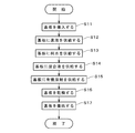
- FIG. 2 is a diagram showing the flow of processing of the substrate 9 in the substrate processing apparatus 1.
- an unprocessed substrate 9 is carried into the chamber 5 by an external transport mechanism and held by the spin chuck 22 (step S11).
- the guard lifting mechanism 26 lowers the guard portion 25 to prevent the substrate 9 to be loaded from coming into contact with the guard portion 25 (the same is true for unloading the substrate 9 described later).
- the guard unit 25 rises to the position shown in FIG. 1, and the upper end of the guard unit 25 is disposed above the substrate 9.
- the second upper nozzle 32 is disposed at a position facing the central portion of the upper surface 91 of the substrate 9 by the nozzle moving mechanism, and the substrate 9 is rotated at a predetermined rotational speed (rotational speed) by the spin motor 21. Is started. Then, by opening the on-off valve 451, the chemical liquid is continuously supplied to the upper surface 91 via the second upper nozzle 32 (step S12). The chemical solution on the upper surface 91 spreads to the outer edge portion by the rotation of the substrate 9, and the chemical solution is supplied to the entire upper surface 91. Further, the chemical liquid scattered from the outer edge portion is received and collected by the inner surface of the cup portion 23.
- the chemical liquid is a cleaning liquid containing, for example, dilute hydrofluoric acid (DHF) or aqueous ammonia.
- the chemical solution may be used for processing other than cleaning, such as removal or development of the oxide film on the substrate 9 or etching.
- the supply of the chemical solution is continued for a predetermined time, and then stopped by closing the on-off valve 451.
- the second upper nozzle 32 may swing in the horizontal direction by the nozzle moving mechanism.
- pure water may be supplied to the lower surface of the substrate 9 by the pure water supply unit 42 via the lower nozzle 34 (the same applies to steps S13 to S15 described later).
- the second upper nozzle 32 moves to the standby position, and then the first upper nozzle 31 is disposed at the facing position.
- pure water room temperature pure water
- the pure water passes through the first upper nozzle 31.
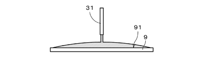
- 91 is continuously supplied (step S13).
- the rinse process in which the chemical
- the entire upper surface 91 is covered with pure water as shown in FIG.
- the rotation of the substrate 9 at a relatively high rotational speed by the spin motor 21 of FIG. 1 is continued.
- the rotation speed is 500 rpm, which is the same when supplying a mixed liquid described later.
- the pure water scattered from the substrate 9 is received by the inner surface of the cup portion 23 and discharged to the outside.
- the supply of pure water is stopped by closing the on-off valve 452. Subsequently, the on-off valves 453 and 454 are opened simultaneously. As a result, heated pure water (hereinafter referred to as “warm pure water”) from the heater 44 and an organic solvent at room temperature are supplied to the internal space of the connection portion 45, and a mixed liquid (diluted) in which the organic solvent and warm pure water are mixed. An organic solvent) is generated at the connection 45.
- heated pure water hereinafter referred to as “warm pure water”
- an organic solvent at room temperature are supplied to the internal space of the connection portion 45, and a mixed liquid (diluted) in which the organic solvent and warm pure water are mixed.
- An organic solvent is generated at the connection 45.
- the normal temperature is the ambient temperature of the substrate processing apparatus 1 and is, for example, in the range of 20 ° C. ⁇ 15 ° C.
- the temperature of warm pure water is higher than normal temperature, for example, 50 ° C. or higher, and preferably 65 ° C. or higher (in practice, 90 ° C. or lower).
- the on-off valve 471 is opened in advance, and the heater 44 can supply hot pure water having a substantially constant temperature.
- the organic solvent is, for example, IPA (isopropyl alcohol), methanol, ethanol, acetone or the like, and has a lower surface tension than pure water.
- the organic solvent preferably has a higher vapor pressure than pure water. In this embodiment, IPA is used as the organic solvent.
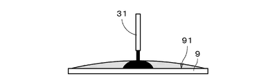
- the mixed liquid is continuously supplied to the upper surface 91 through the first upper nozzle 31 (step S14). As shown in FIG. 4, the mixed solution supplied to the central portion of the upper surface 91 spreads to the outer edge portion by the rotation of the substrate 9, and the pure water on the upper surface 91 is replaced with the mixed solution.
- the liquid mixture scattered from the substrate 9 is received by the inner surface of the cup portion 23.
- the control unit 10 controls the opening of the flow control valve 462 connected to the organic solvent supply unit 43 and the opening of the flow control valve 461 connected to the heater 44, thereby
- the mixing ratio of the solvent and warm pure water that is, the concentration of the organic solvent in the mixed solution is adjusted to a predetermined value.
- the concentration of the organic solvent in the mixed solution will be described later.
- the temperature of the substrate 9 also rises due to the mixed liquid having a temperature higher than room temperature.
- An in-line mixer or the like may be provided between the first upper nozzle 31 and the connection portion 45.
- the on-off valve 453 is closed while the on-off valve 454 is kept open.
- the supply of hot pure water to the connection portion 45 is eliminated, and only the organic solvent at approximately room temperature (pure organic solvent) is continuously supplied to the upper surface 91 via the first upper nozzle 31 (step S15).
- the entire upper surface 91 is covered with the organic solvent.
- the organic solvent scattered from the substrate 9 is received by the inner surface of the cup portion 23.
- the rotation speed of the substrate 9 at the time of supplying the organic solvent is lower than that at the time of supplying the mixed liquid (for example, 200 rpm).
- the supply flow rate of the organic solvent is reduced by controlling the opening degree of the flow rate control valve 462 after a predetermined time has elapsed since the start of the supply of only the organic solvent. Thereby, the thickness of the liquid film of the organic solvent on the upper surface 91 is reduced.
- step S16 the rotational speed of the substrate 9 is increased to, for example, 1500 rpm, whereby a drying process for removing the organic solvent on the upper surface 91 is performed.
- the substrate 9 is carried out of the chamber 5 by an external transfer mechanism (step S17).
- a process of a comparative example in which a pure water liquid film is formed (so-called pure water paddle) after rinsing with pure water will be described.
- the rotational speed of the substrate 9 and the supply flow rate of pure water are reduced, and a relatively thick pure water liquid film is formed on the upper surface. 91 is formed.
- the rotation speed of the substrate 9 is, for example, 10 rpm.
- an organic solvent is supplied onto the upper surface 91 to form a liquid film of the organic solvent.
- the organic solvent spreads over the entire upper surface 91 so as to enter between the liquid film of pure water and the upper surface 91 of the substrate 9.
- the mixed liquid is not supplied.
- the organic solvent on the upper surface 91 is removed by the rotation of the substrate 9.
- the drying of the substrate 9 is completed after the rinsing process. The time required for the processing related to the drying until it becomes longer (that is, the throughput decreases).
- Pattern elements can collapse.
- the cause of the collapse of the pattern element is not necessarily clear, but one reason is that the local area where there is very little pure water (that is, a small amount of pure water that can affect the surface tension of the pattern element). This is a region where there is only a local area, and is hereinafter referred to as “local drying”).
- the organic solvent supplied to the central portion of the upper surface 91 spreads so as to push out pure water on the upper surface 91 (a thin layer is formed by high-speed rotation of the substrate 9), that is, the organic solvent and the pure solvent.
- the organic solvent spreads on the upper surface 91 so that the interface with water moves from the vicinity of the center toward the outer edge.
- pure water, a mixed solution, and an organic solvent are sequentially supplied to the upper surface 91 of the rotating substrate 9, and then the organic solvent on the upper surface 91 is removed by the rotation of the substrate 9. Is done.
- a mixed liquid having higher solubility with pure water than an organic solvent (and a difference in surface tension with pure water is smaller than that of an organic solvent) is supplied to the upper surface 91 to which pure water is applied, thereby mixing Local drying of the upper surface 91 is less likely to occur at the interface between the liquid and pure water.
- the collapse of the pattern element can be suppressed while omitting the process of forming the pure water liquid film.
- the substrate 9 since the substrate 9 is heated by the mixed liquid having a temperature higher than the normal temperature, the substrate 9 can be dried in a short time, and the time required for the processing related to the drying is shortened (throughput is improved). )be able to.
- the mixed liquid is supplied to the upper surface 91 while rotating the substrate 9 at a relatively high number of revolutions, so that the mixed liquid can be spread over the entire upper surface 91 in a short time. Therefore, the time required for supplying the mixed liquid in step S14 can be shortened as compared with the formation process of the pure water liquid film accompanied by the low-speed rotation of the substrate for a certain time. Actually, since the solubility of the mixed solution and the organic solvent is high, the organic solvent can be filled in the minute gaps between the pattern elements in a short time when the organic solvent is supplied in step S15. The time required for this can also be shortened.
- step S14 by shortening the processing time in steps S14 and S15, the time required for the processing relating to drying can be further shortened in combination with the shortening of the drying processing time in step S16. Also, the amount of organic solvent supplied in step S15 can be reduced.
- steps S13 to S15 the pure water, the mixed liquid, and the organic solvent are sequentially discharged from the same first upper nozzle 31, so that the processing related to the discharge of these processing liquids can be simplified. Note that, depending on the design of the substrate processing apparatus 1, pure water, a mixed solution, and an organic solvent may be discharged from different nozzles.
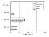
- FIG. 5 and FIG. 6 are diagrams showing experimental results obtained by examining the relationship between the concentration of the organic solvent (here, IPA) in the mixed solution and the solubility between the mixed solution and pure water.
- IPA the organic solvent
- a tube having a diameter of 19 mm with one end blocked by a blocking member was prepared, and 15 cc of pure water at room temperature was stored in the tube extended vertically, and the IPA concentration was 10 vol% (volume percent concentration), 20 vol. %, 50 vol%, and 100 vol% of a mixed solution (a pure organic solvent when the IPA concentration is 100 vol%) was poured along the inner surface of the tube.
- the closing member is provided with a sampling tube having a diameter of 3 mm, and a small amount of liquid in the vicinity of the interface between the mixed solution and pure water is sampled after 0.5 minutes, 1 minute and 2 minutes from the injection of the mixed solution. And the IPA concentration of the solution was measured. 5 and FIG. 6 are extracted at positions of 5 mm and 10 mm from the position of the pure water level before injection of the mixed liquid (corresponding to the interface between the mixed liquid and pure water) toward the closing member, respectively. The IPA concentration of the obtained liquid is shown.
- the concentration of the organic solvent in the mixed solution is preferably 50 vol% or less and 10 vol% or more.
- the concentration is 50 vol% or less, the ratio of warm pure water in the mixed solution can be increased (50% or more), and the temperature of the mixed solution can be easily increased.
- the concentration is preferably 30% or less, more preferably 20% or less. In this case, the solubility of the mixed solution in pure water is further increased.
- the substrate processing apparatus 1 can be variously modified.
- the concentration of the organic solvent in the mixed solution is constant, but the concentration of the organic solvent in the mixed solution may be increased stepwise.
- step S14 the supply flow rate of the organic solvent from the organic solvent supply unit 43 to the connection unit 45 is gradually increased, and the supply flow rate of pure water from the heater 44 to the connection unit 45 is gradually reduced.
- a mixed liquid having a temperature higher than normal temperature may be generated by heating a mixed liquid in which a normal temperature organic solvent and normal temperature pure water are mixed.
- a mixed liquid supply unit that supplies a mixed liquid having a temperature higher than normal temperature to the upper surface 91 is configured using the pure water supply unit 42, the organic solvent supply unit 43, the heater 44, and the connection unit 45 as main components.
- the mixed liquid supply unit may be realized independently of the pure water supply unit 42 and the organic solvent supply unit 43.
- the substrate 9 may be held in various ways.
- the substrate 9 may be held by the substrate holding portion that supports the lower surface of the substrate 9 with the main surface on which the pattern is formed facing upward.
- the substrate processed by the substrate processing apparatus 1 is not limited to a semiconductor substrate, and may be a glass substrate or another substrate.
Landscapes
- Engineering & Computer Science (AREA)
- Chemical & Material Sciences (AREA)
- Life Sciences & Earth Sciences (AREA)
- Health & Medical Sciences (AREA)
- Chemical Kinetics & Catalysis (AREA)
- Molecular Biology (AREA)
- Mechanical Engineering (AREA)
- General Engineering & Computer Science (AREA)
- General Chemical & Material Sciences (AREA)
- Emergency Medicine (AREA)
- Oil, Petroleum & Natural Gas (AREA)
- Wood Science & Technology (AREA)
- Organic Chemistry (AREA)
- Cleaning Or Drying Semiconductors (AREA)
Abstract
Description
9 基板
10 制御部
21 スピンモータ
22 スピンチャック
42 純水供給部
43 有機溶剤供給部
44 ヒータ
45 接続部
91 (基板の)上面
S11~S17 ステップ
Claims (6)
- 基板処理装置であって、
基板を保持する基板保持部と、
前記基板保持部を前記基板と共に回転する基板回転機構と、
前記基板の上方を向く主面に純水を供給する純水供給部と、
純水よりも表面張力が低い有機溶剤と純水とを混合することにより生成され、常温よりも高い温度の混合液を前記主面に供給する混合液供給部と、
前記有機溶剤を前記主面に供給する有機溶剤供給部と、
前記基板回転機構により回転する前記基板の前記主面に、前記純水供給部、前記混合液供給部および前記有機溶剤供給部により前記純水、前記混合液および前記有機溶剤を順に供給させた後、前記基板の回転により前記主面上の前記有機溶剤を除去する制御部と、
を備える。 - 請求項1に記載の基板処理装置であって、
前記混合液が、常温の有機溶剤と加熱した純水とを混合することにより生成される。 - 請求項2に記載の基板処理装置であって、
前記混合液における前記有機溶剤の濃度が50vol%以下である。 - 基板処理方法であって、
a)回転する基板の上方を向く主面に純水を供給する工程と、
b)純水よりも表面張力が低い有機溶剤と純水とを混合することにより生成され、常温よりも高い温度の混合液を、回転する前記基板の前記主面に供給する工程と、
c)回転する前記基板の前記主面に前記有機溶剤を供給する工程と、
d)前記基板の回転により前記主面上の前記有機溶剤を除去する工程と、
を備える。 - 請求項4に記載の基板処理方法であって、
前記混合液が、常温の有機溶剤と加熱した純水とを混合することにより生成される。 - 請求項5に記載の基板処理方法であって、
前記混合液における前記有機溶剤の濃度が50vol%以下である。
Priority Applications (3)
| Application Number | Priority Date | Filing Date | Title |
|---|---|---|---|
| CN201780010108.0A CN108604548B (zh) | 2016-03-17 | 2017-01-24 | 基板处理装置以及基板处理方法 |
| US16/069,532 US10903092B2 (en) | 2016-03-17 | 2017-01-24 | Substrate processing apparatus and substrate processing method |
| KR1020187022272A KR102116195B1 (ko) | 2016-03-17 | 2017-01-24 | 기판 처리 장치 및 기판 처리 방법 |
Applications Claiming Priority (2)
| Application Number | Priority Date | Filing Date | Title |
|---|---|---|---|
| JP2016-053268 | 2016-03-17 | ||
| JP2016053268A JP6613181B2 (ja) | 2016-03-17 | 2016-03-17 | 基板処理装置および基板処理方法 |
Publications (1)
| Publication Number | Publication Date |
|---|---|
| WO2017159052A1 true WO2017159052A1 (ja) | 2017-09-21 |
Family
ID=59850655
Family Applications (1)
| Application Number | Title | Priority Date | Filing Date |
|---|---|---|---|
| PCT/JP2017/002401 Ceased WO2017159052A1 (ja) | 2016-03-17 | 2017-01-24 | 基板処理装置および基板処理方法 |
Country Status (6)
| Country | Link |
|---|---|
| US (1) | US10903092B2 (ja) |
| JP (1) | JP6613181B2 (ja) |
| KR (1) | KR102116195B1 (ja) |
| CN (1) | CN108604548B (ja) |
| TW (1) | TWI682451B (ja) |
| WO (1) | WO2017159052A1 (ja) |
Cited By (2)
| Publication number | Priority date | Publication date | Assignee | Title |
|---|---|---|---|---|
| CN112309903A (zh) * | 2019-07-29 | 2021-02-02 | 株式会社斯库林集团 | 基板处理方法及基板处理装置 |
| WO2022024590A1 (ja) * | 2020-07-31 | 2022-02-03 | 株式会社Screenホールディングス | 基板処理方法 |
Families Citing this family (12)
| Publication number | Priority date | Publication date | Assignee | Title |
|---|---|---|---|---|
| JP6820736B2 (ja) * | 2016-12-27 | 2021-01-27 | 東京エレクトロン株式会社 | 基板処理方法および基板処理装置 |
| US11437250B2 (en) * | 2018-11-15 | 2022-09-06 | Tokyo Electron Limited | Processing system and platform for wet atomic layer etching using self-limiting and solubility-limited reactions |
| US12243752B2 (en) | 2018-11-15 | 2025-03-04 | Tokyo Electron Limited | Systems for etching a substrate using a hybrid wet atomic layer etching process |
| US12444610B2 (en) | 2018-11-15 | 2025-10-14 | Tokyo Electron Limited | Methods for etching a substrate using a hybrid wet atomic layer etching process |
| KR102489739B1 (ko) | 2019-09-26 | 2023-01-20 | 세메스 주식회사 | 기판 처리 장치 및 처리액 공급 방법 |
| JP7592500B2 (ja) * | 2021-01-18 | 2024-12-02 | 東京エレクトロン株式会社 | 基板処理方法および基板処理装置 |
| US11915941B2 (en) | 2021-02-11 | 2024-02-27 | Tokyo Electron Limited | Dynamically adjusted purge timing in wet atomic layer etching |
| US12506014B2 (en) | 2021-10-19 | 2025-12-23 | Tokyo Electron Limited | Methods for non-isothermal wet atomic layer etching |
| US12276033B2 (en) | 2021-10-19 | 2025-04-15 | Tokyo Electron Limited | Methods for wet etching of noble metals |
| US11802342B2 (en) | 2021-10-19 | 2023-10-31 | Tokyo Electron Limited | Methods for wet atomic layer etching of ruthenium |
| US11866831B2 (en) | 2021-11-09 | 2024-01-09 | Tokyo Electron Limited | Methods for wet atomic layer etching of copper |
| US12506011B2 (en) | 2023-12-15 | 2025-12-23 | Tokyo Electron Limited | Methods for wet atomic layer etching of transition metal oxide dielectric materials |
Citations (5)
| Publication number | Priority date | Publication date | Assignee | Title |
|---|---|---|---|---|
| JP2007335815A (ja) * | 2006-06-19 | 2007-12-27 | Dainippon Screen Mfg Co Ltd | 基板処理方法および基板処理装置 |
| JP2010129809A (ja) * | 2008-11-28 | 2010-06-10 | Dainippon Screen Mfg Co Ltd | 基板処理方法および基板処理装置 |
| JP2013542607A (ja) * | 2010-10-28 | 2013-11-21 | ラム・リサーチ・アーゲー | 半導体ウエハを乾燥させるための方法および装置 |
| JP2014072439A (ja) * | 2012-09-28 | 2014-04-21 | Dainippon Screen Mfg Co Ltd | 基板処理方法および基板処理装置 |
| JP2015092539A (ja) * | 2013-09-30 | 2015-05-14 | 芝浦メカトロニクス株式会社 | 基板処理装置及び基板処理方法 |
Family Cites Families (8)
| Publication number | Priority date | Publication date | Assignee | Title |
|---|---|---|---|---|
| TW386235B (en) | 1995-05-23 | 2000-04-01 | Tokyo Electron Ltd | Method for spin rinsing |
| JP3684356B2 (ja) | 2002-03-05 | 2005-08-17 | 株式会社カイジョー | 洗浄物の乾燥装置及び乾燥方法 |
| JP4762098B2 (ja) * | 2006-09-28 | 2011-08-31 | 大日本スクリーン製造株式会社 | 基板処理装置および基板処理方法 |
| JP5139844B2 (ja) | 2008-03-04 | 2013-02-06 | 大日本スクリーン製造株式会社 | 基板処理方法および基板処理装置 |
| JP5114252B2 (ja) | 2008-03-06 | 2013-01-09 | 大日本スクリーン製造株式会社 | 基板処理方法および基板処理装置 |
| JP5955766B2 (ja) | 2012-12-28 | 2016-07-20 | 東京エレクトロン株式会社 | 基板処理装置および基板処理方法 |
| JP5736017B2 (ja) * | 2013-09-09 | 2015-06-17 | 株式会社Screenホールディングス | 基板処理方法および基板処理装置 |
| JP6438649B2 (ja) * | 2013-12-10 | 2018-12-19 | 株式会社Screenホールディングス | 基板処理方法および基板処理装置 |
-
2016
- 2016-03-17 JP JP2016053268A patent/JP6613181B2/ja active Active
-
2017
- 2017-01-24 WO PCT/JP2017/002401 patent/WO2017159052A1/ja not_active Ceased
- 2017-01-24 KR KR1020187022272A patent/KR102116195B1/ko active Active
- 2017-01-24 CN CN201780010108.0A patent/CN108604548B/zh active Active
- 2017-01-24 US US16/069,532 patent/US10903092B2/en active Active
- 2017-02-14 TW TW106104749A patent/TWI682451B/zh active
Patent Citations (5)
| Publication number | Priority date | Publication date | Assignee | Title |
|---|---|---|---|---|
| JP2007335815A (ja) * | 2006-06-19 | 2007-12-27 | Dainippon Screen Mfg Co Ltd | 基板処理方法および基板処理装置 |
| JP2010129809A (ja) * | 2008-11-28 | 2010-06-10 | Dainippon Screen Mfg Co Ltd | 基板処理方法および基板処理装置 |
| JP2013542607A (ja) * | 2010-10-28 | 2013-11-21 | ラム・リサーチ・アーゲー | 半導体ウエハを乾燥させるための方法および装置 |
| JP2014072439A (ja) * | 2012-09-28 | 2014-04-21 | Dainippon Screen Mfg Co Ltd | 基板処理方法および基板処理装置 |
| JP2015092539A (ja) * | 2013-09-30 | 2015-05-14 | 芝浦メカトロニクス株式会社 | 基板処理装置及び基板処理方法 |
Cited By (6)
| Publication number | Priority date | Publication date | Assignee | Title |
|---|---|---|---|---|
| CN112309903A (zh) * | 2019-07-29 | 2021-02-02 | 株式会社斯库林集团 | 基板处理方法及基板处理装置 |
| US11524314B2 (en) * | 2019-07-29 | 2022-12-13 | SCREEN Holdings Co., Ltd. | Substrate processing method and substrate processing device |
| WO2022024590A1 (ja) * | 2020-07-31 | 2022-02-03 | 株式会社Screenホールディングス | 基板処理方法 |
| JP2022027088A (ja) * | 2020-07-31 | 2022-02-10 | 株式会社Screenホールディングス | 基板処理方法 |
| JP7562329B2 (ja) | 2020-07-31 | 2024-10-07 | 株式会社Screenホールディングス | 基板処理方法 |
| US12255061B2 (en) | 2020-07-31 | 2025-03-18 | SCREEN Holdings Co., Ltd. | Substrate processing method |
Also Published As
| Publication number | Publication date |
|---|---|
| CN108604548A (zh) | 2018-09-28 |
| JP6613181B2 (ja) | 2019-11-27 |
| TW201802910A (zh) | 2018-01-16 |
| TWI682451B (zh) | 2020-01-11 |
| CN108604548B (zh) | 2022-11-01 |
| US20190027383A1 (en) | 2019-01-24 |
| JP2017168699A (ja) | 2017-09-21 |
| KR20180099864A (ko) | 2018-09-05 |
| KR102116195B1 (ko) | 2020-05-27 |
| US10903092B2 (en) | 2021-01-26 |
Similar Documents
| Publication | Publication Date | Title |
|---|---|---|
| JP6613181B2 (ja) | 基板処理装置および基板処理方法 | |
| TWI698906B (zh) | 基板處理方法以及基板處理裝置 | |
| US10854481B2 (en) | Substrate processing method and substrate processing apparatus | |
| CN107871691B (zh) | 基板处理方法和基板处理装置 | |
| TWI636158B (zh) | 基板處理方法及基板處理裝置 | |
| CN110098137B (zh) | 基板处理方法及基板处理装置 | |
| JP2010050143A (ja) | 基板処理方法および基板処理装置 | |
| JP2009212301A (ja) | 基板処理方法および基板処理装置 | |
| JP2010129809A (ja) | 基板処理方法および基板処理装置 | |
| TW201622835A (zh) | 基板處理方法及基板處理裝置 | |
| JP2017041512A (ja) | 基板処理方法および基板処理装置 | |
| JP6916003B2 (ja) | 基板処理方法および基板処理装置 | |
| JP6710561B2 (ja) | 基板処理方法および基板処理装置 | |
| JP6710608B2 (ja) | 基板処理方法 | |
| JP5736017B2 (ja) | 基板処理方法および基板処理装置 | |
| JP2015130542A (ja) | 基板処理方法および基板処理装置 | |
| JP2017103500A (ja) | 基板処理方法および基板処理装置 |
Legal Events
| Date | Code | Title | Description |
|---|---|---|---|
| ENP | Entry into the national phase |
Ref document number: 20187022272 Country of ref document: KR Kind code of ref document: A |
|
| WWE | Wipo information: entry into national phase |
Ref document number: 1020187022272 Country of ref document: KR |
|
| NENP | Non-entry into the national phase |
Ref country code: DE |
|
| 121 | Ep: the epo has been informed by wipo that ep was designated in this application |
Ref document number: 17766060 Country of ref document: EP Kind code of ref document: A1 |
|
| 122 | Ep: pct application non-entry in european phase |
Ref document number: 17766060 Country of ref document: EP Kind code of ref document: A1 |